EP3363660A1 - Kraftfahrzeugrad - Google Patents
Kraftfahrzeugrad Download PDFInfo
- Publication number
- EP3363660A1 EP3363660A1 EP18151543.8A EP18151543A EP3363660A1 EP 3363660 A1 EP3363660 A1 EP 3363660A1 EP 18151543 A EP18151543 A EP 18151543A EP 3363660 A1 EP3363660 A1 EP 3363660A1
- Authority
- EP
- European Patent Office
- Prior art keywords
- vehicle
- rim
- rolling resistance
- heat
- tire
- Prior art date
- Legal status (The legal status is an assumption and is not a legal conclusion. Google has not performed a legal analysis and makes no representation as to the accuracy of the status listed.)
- Granted
Links
Images
Classifications
-
- B—PERFORMING OPERATIONS; TRANSPORTING
- B60—VEHICLES IN GENERAL
- B60C—VEHICLE TYRES; TYRE INFLATION; TYRE CHANGING; CONNECTING VALVES TO INFLATABLE ELASTIC BODIES IN GENERAL; DEVICES OR ARRANGEMENTS RELATED TO TYRES
- B60C99/00—Subject matter not provided for in other groups of this subclass
- B60C99/003—Tyre heating arrangements
-
- B—PERFORMING OPERATIONS; TRANSPORTING
- B60—VEHICLES IN GENERAL
- B60C—VEHICLE TYRES; TYRE INFLATION; TYRE CHANGING; CONNECTING VALVES TO INFLATABLE ELASTIC BODIES IN GENERAL; DEVICES OR ARRANGEMENTS RELATED TO TYRES
- B60C11/00—Tyre tread bands; Tread patterns; Anti-skid inserts
- B60C11/03—Tread patterns
- B60C11/13—Tread patterns characterised by the groove cross-section, e.g. for buttressing or preventing stone-trapping
- B60C11/1307—Tread patterns characterised by the groove cross-section, e.g. for buttressing or preventing stone-trapping with special features of the groove walls
- B60C11/1346—Tread patterns characterised by the groove cross-section, e.g. for buttressing or preventing stone-trapping with special features of the groove walls covered by a rubber different from the tread rubber
-
- B—PERFORMING OPERATIONS; TRANSPORTING
- B60—VEHICLES IN GENERAL
- B60C—VEHICLE TYRES; TYRE INFLATION; TYRE CHANGING; CONNECTING VALVES TO INFLATABLE ELASTIC BODIES IN GENERAL; DEVICES OR ARRANGEMENTS RELATED TO TYRES
- B60C13/00—Tyre sidewalls; Protecting, decorating, marking, or the like, thereof
- B60C13/04—Tyre sidewalls; Protecting, decorating, marking, or the like, thereof having annular inlays or covers, e.g. white sidewalls
-
- B—PERFORMING OPERATIONS; TRANSPORTING
- B60—VEHICLES IN GENERAL
- B60C—VEHICLE TYRES; TYRE INFLATION; TYRE CHANGING; CONNECTING VALVES TO INFLATABLE ELASTIC BODIES IN GENERAL; DEVICES OR ARRANGEMENTS RELATED TO TYRES
- B60C19/00—Tyre parts or constructions not otherwise provided for
-
- B—PERFORMING OPERATIONS; TRANSPORTING
- B60—VEHICLES IN GENERAL
- B60C—VEHICLE TYRES; TYRE INFLATION; TYRE CHANGING; CONNECTING VALVES TO INFLATABLE ELASTIC BODIES IN GENERAL; DEVICES OR ARRANGEMENTS RELATED TO TYRES
- B60C2200/00—Tyres specially adapted for particular applications
- B60C2200/06—Tyres specially adapted for particular applications for heavy duty vehicles
Definitions
- the invention relates to a motor vehicle wheel comprising a vehicle rim made of metal and mounted on this vehicle rim pneumatic vehicle tire, wherein on the surface of the vehicle rim and / or on the surface of the pneumatic vehicle tire, a heat insulation in the form of an additional heat-insulating layer is arranged.
- Vehicle tire rims are usually made of metallic materials. All rims, especially those based on metallic materials, are characterized by a high thermal conductivity of the material used. Since the vehicle pneumatic tire heats up during its use due to hysteresis losses, heating of the tire interior filled with compressed air and thus of the tire rim also sets in. Due to the high thermal conductivity of the rim material commonly used, there is a significant heat transfer from the wheel into the environment via the rim surface. However, it has been shown that by increasing the running temperature of a motor vehicle tire, the rolling resistance of this tire can be reduced, that is, improved.
- the tire interior is the cavity formed by the rim and rim-mounted tire in the interior thereof.
- the invention is based on the object to provide a motor vehicle wheel, which is particularly effective rolling resistance optimized, but the vehicle pneumatic tires continue to have a high structural durability. Furthermore, it is the object to provide a commercial vehicle available, which is particularly efficient rolling resistance optimized.
- the object is achieved in relation to the motor vehicle wheel, which comprises a vehicle rim made of metal and a vehicle pneumatic tire mounted on this vehicle rim and wherein heat insulation in the form of an additional heat-insulating layer is arranged on the surface of the vehicle rim and / or on the surface of the pneumatic vehicle tire in that the "bare" pneumatic vehicle tire mounted on the rim has a rolling resistance ⁇ 6.04 kg / t, the rolling resistance being determined according to the rolling resistance test ISO 28580.
- Body pneumatic vehicle tire means a commercial pneumatic vehicle tire without additional heat-insulating layer.
- a thermally insulated rim and / or a heat-insulated pneumatic vehicle tire is combined with the use of a rolling resistance-optimized tire.
- a commercial vehicle pneumatic tire with a rolling resistance ⁇ 6.04 kg / t is at least equivalent to EU rolling resistance label C or better.
- These rolling resistance optimized tires are generally less susceptible to wear in use due to their comparatively low rolling resistance than tires with higher rolling resistance and thereby also reduced tire running temperature compared to standard higher rolling resistance tires.
- the heat-insulated vehicle wheel according to the invention causes a comparatively large increase in the tire interior temperature with respect to standard tires. This large increase in tire tread temperature has a positive effect on the rolling resistance but not on the structural durability of the tire.
- the vehicle rim is an aluminum vehicle rim. As a result, a low weight of the vehicle is obtained, which has a positive effect on the fuel consumption of the vehicle.
- the bare pneumatic vehicle tire has a rolling resistance ⁇ 5.04 kg / t, preferably ⁇ 4.04 kg / t, wherein the rolling resistance is determined according to the rolling resistance test ISO 28580.
- a particularly high structural durability of the tire is made possible even in the event that the tire running temperature is significantly increased by thermal insulation of the tire or heat insulation of the rim.
- a heat-insulating layer preferably a layer of open-cell polyurethane foam disposed in the low bed of the vehicle rim, which rotates as an open, closed or open-ended ring or segments of a ring over the circumference of the well.
- the polyurethane foam has a three-dimensional open-celled nature and a thickness ⁇ 12 mm and an elongation at break ⁇ 40% and a compressive stress ⁇ 20 kPa.
- the elongation at break is determined according to ISO 1798.
- the compressive stress is determined according to ISO 3386.
- the foam has a density between 10 and 100 kg / m 3 , preferably between 15 and 40 kg / m 3 .
- the density is determined according to ISO 845.
- the foam has a compressive stress of between 5 and 10 kPa determined at 40%.
- the tensile stress is determined according to ISO 3386.
- the foam has a tensile strength ⁇ 60 kPa, preferably ⁇ 90 kPa.
- the tensile strength is determined according to ISO 1798.
- the foam has an elongation at break ⁇ 70%. The elongation at break is determined according to ISO 1798.
- the foam has a maximum axial extent, which covers the area of the rim inside, which remains between the two seated on the rim seat bead toes of Reifenwülste and has a minimum axial extent, which 0.6 x the maximum axial Extension corresponds.
- the foam has a thickness ⁇ 15 mm, preferably ⁇ 20 mm, but does not exceed 30% of the tire interior height, wherein the thickness of the foam is measured in the radial direction and wherein the tire interior height is measured at the highest height location between the rim inside and the tire inner layer.
- the foam consists of polyether-based polyurethane. Polyether-based polyurethane foams have a particularly high hydrolysis resistance, which has an advantageous effect on the lasting robustness of the foam.
- the vehicle rim has a width of at least 5 inches, preferably greater than 10 inches. It has surprisingly been found to be particularly effective for improved rolling resistance to isolate wide vehicle rims.
- the invention is achieved in that the commercial vehicle has heat-insulated motor vehicle wheels on at least one axle according to one or more of the preceding embodiments.
- the optimization of the rolling resistance is particularly effective if at least one axle of the trailer, preferably all axles of the trailer are equipped with heat-insulating vehicle wheels.
- the tractor is particularly efficient in terms of cost / benefit optimized rolling resistance when the drive axle (s) of the tractor have heat-insulating vehicle wheels.
- it is particularly efficient if only the drive axle (s) of the towing vehicle has the heat-insulated vehicle wheels and the steering axle has no heat-insulating vehicle wheels.
- Table 3 shows the result of fuel consumption measurements of a commercial vehicle with vehicle wheels with standard wheels compared to vehicle wheels according to the invention, in which the rims heat insulated and the tires mounted on the rim have a rolling resistance ⁇ 6.04 kg / t.
- the vehicle used in the test runs was operated on the steering axle and the drive axle with 315/70 R 22.5 "tires on 9.00 R 22.5" aluminum rims, the vehicle being equipped with a steering axle with two wheels and a drive axle with four wheels , This tractor was connected to a 3-axle semi-trailer with six 385/55 R 22.5 "tires on 11.75 R 22.5" aluminum wheels.
- the gross vehicle weight was 40 metric tons.
- one set of non-heat-insulated rims was compared to a set of thermally-insulated rims compared with each other, this comparison being performed several times in three separate test runs.
- the non-heat-insulated rims have been commercially available aluminum rims, in the heat-insulated rims same commercial aluminum rims were equipped with a heat insulation layer in the rim well.
- an open-cell polyether-based polyurethane foam having a bulk density of 26 kg / m 3 and a thickness of 20 mm was applied in the low bed of the aluminum rim over its entire axial width. The foam was stuck with epoxy resin adhesive on the rim. Tab.
- Table 4 shows results from consumption measurements with respect to the change in the rim interior temperature by insulation of the rim.
- the experimental conditions are as previously described.
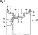
- the Fig. 1 shows a Tiefbettfelge conventional design with heat insulating layer in cross section with a rim base 1, on both sides of this subsequent rim shoulders 4 with bead seat surfaces 4a and with rim flanges 3.
- the rim also has a wheel disc or a rim 2, which in which As known, a wheel hub region for arranging the rim on a Aufhahmeflansch a wheel bearing of a motor vehicle.
- An unillustrated rim-mounted vehicle pneumatic tire is in contact with the bead seat surfaces 4a and the rim flanges 3 with its bead portions.
- the heat-insulating layer 5a extends over the outer side 1a of the rim base 1 and up to the two bead seat surfaces 4a, but not over the bead seat surfaces 4a.
- the heat-insulating layer 5b is located on the inner side 1b of the rim base 1, furthermore on the inner sides 4b of the rim shoulders 4 and the inner sides 3b of the rim flanges 3.
- further heat-insulating layers 5c are on both sides of the first outgoing from the inner side 1b of the rim base 1 Section 2a of the wheel disc or the wheel rim 2 applied.
- the heat-insulating layers 5a, 5b, 5c consist for example of flock fibers or a foam such as polyurethane, which are glued, for example, on the rim.
- the polyurethane system used may be polyether-based or polyester-based.
- the foam layer formed can be open-cell, mixed-cell or closed-cell and is produced with a thickness of 1 mm up to 30 mm, in particular up to 20 mm.
- the Shore A hardness of the foam according to DIN ISO 7619-1 can be between 0 and 50 Shore A, its density is between 0.01 g / cm 3 and 0.90 g / cm 3 .
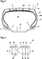
- Fig. 2 schematically shows a cross section of a pneumatic vehicle tire 6 for commercial vehicles, mounted on a Tiefbettfelge 23 with a rim 1, rim shoulders 4 and rim flanges 3.
- the pneumatic vehicle tire 6 has a tread 7 with a profiling, of which exemplary circumferential grooves 8 are shown.
- the tread 7 may have further, not shown tread grooves, for example, extend in the axial direction and form together with other tread grooves profile positive, such as tread blocks or tread ribs.
- a belt assembly 9 which may consist of several belt layers in a conventional manner, a single or multi-layer carcass ply 10, which may also be performed in a conventional manner and in Wulst Schemeen bead cores 12 wraps around and side walls 13.
- the bead areas 11 abut the rim shoulders 2b and the rim flanges 2c.
- heat insulating layers 14a are provided on each side wall 13.
- the heat insulating layers 14a extend between the outer surfaces of the bead portions 11 and the lateral edges 7a of the ground contact surface of the tread 7 coming into contact with the tire rim 2.
- the heat-insulating layers 14b are linings of tread grooves 8, wherein all tread grooves or some of the tread grooves, at least partially, in particular completely, are lined with heat-insulating layers 14b. Particularly suitable for lining are tread grooves whose minimum width at the tread outer surface is 3 mm.
- the thermally insulated rim of the Fig. 1 can with a thermally insulated tire the Fig.2 be combined.
- the Fig. 3 shows a commercial vehicle according to the invention 16 of tractor 17 and semi-trailer 18 with wheels, which are partially formed thermally insulated.
- the tractor has a steering axle 19 and a drive axle 20, while the semi-trailer has three trailer axles 21.
- the wheels of the drive axle 20 and the wheels of the semi-trailer axles 21 are thermally insulated, for example as in the Fig. 1 and or Fig. 2 described way.
Landscapes
- Engineering & Computer Science (AREA)
- Mechanical Engineering (AREA)
- Tires In General (AREA)
Abstract
Description
- Die Erfindung betrifft ein Kraftfahrzeugrad umfassend eine Fahrzeugfelge aus Metall und einen auf diese Fahrzeugfelge aufgezogenen Fahrzeugluftreifen, wobei auf der Oberfläche der Fahrzeugfelge und/oder auf der Oberfläche des Fahrzeugluftreifens eine Wärmeisolierung in Form einer zusätzlichen wärmeisolierenden Schicht angeordnet ist.
- Fahrzeugreifenfelgen werden üblicherweise aus metallischen Werkstoffen gefertigt. Alle Felgen, insbesondere die auf Basis metallischer Werkstoffe, zeichnen sich durch eine hohe Wärmeleitfähigkeit des eingesetzten Werkstoffes aus. Da sich der Fahrzeugluftreifen während seines Einsatzes aufgrund von Hystereseverlusten erwärmt, stellt sich auch eine Erwärmung des mit komprimierter Luft gefüllten Reifeninnenraumes und damit der Reifenfelge ein. Aufgrund der hohen Wärmeleitfähigkeit des üblicherweise verwendeten Felgenmaterials kommt es über die Felgenoberfläche zu einem signifikaten Wärmetransport aus dem Rad in die Umgebung. Es hat sich jedoch gezeigt, dass durch Erhöhung der Lauftemperatur eines Kraftfahrzeugreifens der Rollwiderstand dieses Reifens reduzierbar, also verbesserbar ist. Der Reifeninnenraum ist der Hohlraum, welcher durch die Felge und den auf der Felge aufsitzende Reifen in dessen Innenraum gebildet ist.
- Es sind verschiedene Arten von Fahrzeugluftreifen und Felgen bekannt, welche eine Wärmeisolierung aufgrund von zusätzlich auf die Oberfläche aufgebrachten wärmeisolierenden Schichten aufweisen.
- So ist es beispielsweise aus der
JP 2004082787 A - Aus der
DE 10 2012 102 418 A1 ist es bekannt, eine wärmeisolierende Schicht aus offenzelligem Material auf der Außenfläche des Felgenringes, insbesondere im Felgenbett, anzuordnen.
Die bisher unveröffentlichte Anmeldung der AnmelderinDE 10 2016 213 467.1 beschreibt eine wärmeisolierende Schicht aus Polyurethanschaum, welche auf den äußeren Oberflächen der Reifenseiten angeordnet sind, während die bisher unveröffentlichte Anmeldung der AnmelderinDE 10 2016 213 467.1 die vorgenannte wärmeisolierende Schicht aus Polyurethanschaum beschreibt, welche auf der Felge angeordnet ist. - Der Erfindung liegt die Aufgabe zu Grunde, ein Kraftfahrzeugrad bereitzustellen, welches besonders wirkungsvoll rollwiderstandsoptimiert ist, jedoch der Fahrzeugluftreifen weiterhin eine hohe strukturelle Haltbarkeit aufweist. Weiterhin ist es die Aufgabe, ein Nutzfahrzeug zur Verfügung zu stellen, welches besonders effizient rollwiderstandsoptimiert ist.
- Gelöst wird die Aufgabe in Bezug auf das Kraftfahrzeugrad, welches eine Fahrzeugfelge aus Metall und einen auf diese Fahrzeugfelge aufgezogenen Fahrzeugluftreifen umfasst und wobei auf der Oberfläche der Fahrzeugfelge und/oder auf der Oberfläche des Fahrzeugluftreifens eine Wärmeisolierung in Form einer zusätzlichen wärmeisolierenden Schicht angeordnet ist, dadurch, dass der auf die Felge aufgezogene "blanke" Fahrzeugluftreifen, einen Rollwiderstand ≤ 6,04 kg/t aufweist, wobei der Rollwiderstand gemäß Rollwiderstandstest ISO 28580 ermittelt ist.
- "Blanker Fahrzeugluftreifen" meint einen handelsüblichen Fahrzeugluftreifen ohne zusätzlich wärmeisolierende Schicht.
- Erfindungsgemäß ist eine wärmeisolierte Felge und/oder ein wärmeisolierter Fahrzeugluftreifen mit dem Einsatz eines rollwiderstandsoptimierten Reifens kombiniert. Ein NFZ-Fahrzeugluftreifen mit einem Rollwiderstand ≤ 6,04 kg/t entspricht mindestens dem EU-Rollwiderstandslabel C oder besser. Diese bereits in ihrem Aufbau rollwiderstandsoptimierten Reifen weisen allgemein im Gebrauch aufgrund ihres vergleichsweise niedrigen Rollwiderstandes eine geringere Wärmedissipation auf als Reifen mit einem höheren Rollwiderstand und dadurch auch eine reduzierte Reifenlauftemperatur verglichen mit Standardreifen mit höherem Rollwiderstand. Das erfindungsgemäße wärmeisolierte Fahrzeugrad bewirkt eine vergleichsweise starke Erhöhung der Reifeninnenraumtemperatur in Bezug auf Standardreifen. Diese starke Erhöhung der Reifenlauftemperatur wirkt sich positiv auf den Rollwiderstand, aber nicht negativ auf die strukturelle Haltbarkeit des Reifens aus. Dies wird dadurch sichergestellt, dass ein haltbarkeitsschädigendes Temperaturniveaubei diesen rollwiderstandsoptimierten Reifen auch mit zusätzlich wärmeisolierender Schicht auf dem Reifen und/oder der Felge nicht erreicht wird. Somit ist mit dem erfindungsgemäßen Fahrzeugrad ein besonders wirkungsvoll rollwiderstandsoptimiertes Rad mit hoher struktureller Haltbarkeit erhalten.
- Das EU-Rollwiderstandslabel C oder besser für NFZ-Reifen wird in die nachfolgenden Klassen untergliedert:
- EU-Rollwiderstandslabel C: Rollwiderstand von 5,05 - 6,04 kg/t
- EU-Rollwiderstandslabel B: Rollwiderstand von 4,05 - 5,04 kg/t
- EU-Rollwiderstandslabel A: Rollwiderstand < 4,05 kg/t.
- Es hat sich in Versuchen gezeigt, dass pro °C erhöhte Reifeninnenraumtemperatur ein Rollwiderstandsvorteil von etwa 0,3 bis 0,4 % erreicht ist. Dies wurde mit Rollwiderstandstrommelprüfungen beim Vergleich wärmeisolierter mit nichtwärmeisolierten Felgen ermittelt, bei denen der Rollwiderstand und die Reifeninnenraumtemperatur ermittelt wurde. Hierzu wurde bei dem erfindungsgemäßen Fahrzeugrad im Tiefbett der eingesetzten Aluminiumfelge über dessen gesamte axiale Breite ein offenzelliger Polyurethanschaum auf Polyetherbasis mit einer Rohdichte von 26 kg/m3 und einer Dicke von 20 mm aufgebracht. Der Schaum wurde dabei mit Epoxidharzkleber auf der Felge aufgeklebt.
Die Rollwiderstandsmessung wurde in Anlehnung an die ISO 28580 durchgeführt. Die Ergebnisse dieser Versuche sind in den Tabellen 1 und 2 dargestellt. - Zweckmäßig ist es, wenn die Fahrzeugfelge eine Aluminium-Fahrzeugfelge ist. Hierdurch ist ein niedriges Gewicht des Fahrzeugrades erhalten, was sich positiv auf den Kraftstoffverbrauch des Fahrzeuges auswirkt.
- Vorteilhaft ist es, wenn der blanke Fahrzeugluftreifen einen Rollwiderstand ≤ 5,04 kg/t, bevorzugt ≤ 4,04 kg/t aufweist, wobei der Rollwiderstand gemäß Rollwiderstandstest ISO 28580 ermittelt ist. Hierdurch wird eine besonders hohe strukturelle Haltbarkeit des Reifens auch für den Fall ermöglicht, dass die Reifenlauftemperatur durch Wärmeisolation des Reifens oder Wärmisolation der Felge deutlich erhöht wird.
Tab. 1 Standard (nicht isolierte) Aluminiumfelge wärme-isolierte Aluminiumfelge Reifendimension Felge Achs-position Temperatur Felgenhohlraum bei Teststart (°C) Rollwiderstand (N) Temperatur Felgenhohlraum bei Testende (°C) Rollwiderstand (N) Temperatur Felgenhohlraum bei Testende (°C) Rollwiderstandsvorteil für isolierte Felge (%) 315/70 R 22,5 9.00 R 22,5 Lenkachse 25 159,9 72,8 157,85 77,2 1,3 315/70 R 22,5 9.00 R 22,5 Antriebsachse 25 147,8 67,7 145,25 73,0 1,7 385/55 R 22,5 11.75 R 2,5 Trailerachse 25 146,5 67,5 142,7 74,3 2,6 Tab. 2 Reifendimension Felge Achs-position Temperatur Felgenhohlraum bei Teststart (°C) Temperaturunterschied für die isolierte Felge im Vergleich zur nicht isolieten Felge (°C) Rollwiderstandsvorteil für isolierte Felge (N) Rollwiderstandsvorteil pro °C erhöhte Felgenraumtemperatur (N) Rollwiderstandsvorteil für isolierte Felge (%) Rollwiderstandsvorteil pro °C erhöhte Felgenraumtemperatur (%) 315/70 R 22,5 9.00 R 22,5 Lenkachse 25 4,3 2,05 0,48 -1.3 0.30 315/70 R 22,6 9.00 R 22,5 Antriebsachse 25 5,3 2,55 0,48 -1,7 0,33 385/55 R 22,5 11.75 R 2,5 Trailerachse 25 6,8 3,8 0,56 -2,6 0,38 - In einer bevorzugten Ausführung der Erfindung ist in dem Tiefbett der Fahrzeugfelge eine wärmeisolierende Schicht, vorzugsweise eine Lage aus offenzelligem Polyurethanschaum angeordnet, welche als offener, geschlossener oder durchbrochener Ring oder als Segmente eines Ringes über den Umfang des Tiefbettes umläuft.
- Der Schaum aus Polyurethan weist eine dreidimensionale Offenzelligkeit und eine Dicke ≥ 12 mm sowie eine Bruchdehnung ≥ 40 % und eine Druckspannung ≤ 20 kPa auf. Die Bruchdehnung wird ermittelt nach ISO 1798. Die Druckspannung wird ermittelt nach ISO 3386.
- In einer vorteilhaften Weiterbildung ist vorgesehen, dass der Schaum eine Dichte zwischen 10 und 100 kg/m3, bevorzugt zwischen 15 und 40 kg/m3 aufweist. Die Dichte wird ermittelt nach ISO 845.
In einer vorteilhaften Weiterbildung ist vorgesehen, dass der Schaum eine bei 40% ermittelte Druckspannung zwischen 5 und 10 kPa aufweist. Die Zugspannung wird ermittelt nach ISO 3386.
In einer vorteilhaften Weiterbildung ist vorgesehen, dass
der Schaum eine Zugfestigkeit ≥ 60 kPa, bevorzugt ≥ 90 kPa aufweist. Die Zugfestigkeit wird ermittelt nach ISO 1798.
In einer vorteilhaften Weiterbildung ist vorgesehen, dass der Schaum eine Bruchdehnung ≥ 70 % aufweist. Die Bruchdehnung wird ermittelt nach ISO 1798.
In einer vorteilhaften Weiterbildung ist vorgesehen, dass der Schaum eine maximal axiale Erstreckung aufweist, welche den Bereich der Felgeninnenseite überdeckt, welcher zwischen den beiden auf dem Felgensitz aufsitzenden Wulstzehen der Reifenwülste verbleibt und eine minimale axiale Erstreckung aufweist, welche 0,6 x der maximalen axialen Erstreckung entspricht.
In einer vorteilhaften Weiterbildung ist vorgesehen, dass der Schaum eine Dicke ≥ 15 mm, vorzugsweise ≥ 20 mm aufweist, jedoch nicht 30% der Reifeninnenraumhöhe überschreitet, wobei die Dicke des Schaumes in radialer Richtung gemessen wird und wobei die Reifeninnenraumhöhe an der Stelle größter Höhe zwischen Felgeninnenseite und Reifeninnenschicht gemessen wird.
In einer vorteilhaften Weiterbildung ist vorgesehen, dass der Schaum aus Polyurethan auf Polyetherbasis besteht. Polyurethanschäume auf Polyetherbasis weisen eine besonders hohe Hydrolysebeständigkeit auf, was sich vorteilhaft auf die dauerhafte Robustheit des Schaumes auswirkt. - Zweckmäßig ist es, wenn die Fahrzeugfelge eine Breite von wenigstens 5 Zoll, bevorzugt größer 10 Zoll aufweist. Es hat sich überraschenderweise als besonders wirkungsvoll für einen verbesserten Rollwiderstand erwiesen, breite Fahrzeugfelgen zu isolieren.
- Die Erfindung wird hinsichtlich eines Nutzfahrzeuges mit einer Zugmaschine und einem Auflieger dadurch gelöst, dass das Nutzfahrzeug an wenigstens einer Achse wärmeisolierte Kraftfahrzeugrädern nach einer oder mehrerer der vorangehenden Ausführungen aufweist.
- Überraschender Weise ist die Optimierung des Rollwiderstandes besonders effektiv, wenn wenigstens eine Achse des Trailers, vorzugsweise alle Achsen des Trailers mit wärmeisolierenden Fahrzeugrädern ausgerüstet sind.
- Ebenfalls hat sich überraschenderweise herausgestellt, dass die Zugmaschine besonders effizient in Bezug auf den Kosten-/ Nutzenaufwand rollwiderstandsoptimiert ist, wenn die Antriebsachse(n) der Zugmaschine wärmeisolierende Fahrzeugräder aufweisen. Hierbei ist es besonders effizient, wenn ausschließlich die Antriebsachse(n) der Zugmaschine die wärmeisolierten Fahrzeugräder aufweist(en) und die Lenkachse keine wärmeisolierenden Fahrzeugräder aufweist.
- Die nachfolgende Tabelle 3 zeigt das Ergebnis von Kraftstoff Verbrauchsmessungen eines Nutzfahrzeuges mit Fahrzeugrädern mit Standardfelgeen im Vergleich zu erfindungsgemäßen Fahrzeugrädern, bei denen die Felgen wärmeisoliert und die auf die Felge aufgezogenen Reifen einen Rollwiderstand < 6,04 kg/t aufweisen.
Es wurden drei Testläufe von erfindungsgemäßen wärmeisolierten Fahrzeugrädern an der Lenkachse, der Antriebsachse und der Aufliegerachse eines Nutzfahrzeuges aufweisend eine Zugmaschine und einen Auflieger durchgeführt.
Das in den Testläufen eingesetzte Fahrzeug wurde auf der Lenkachse und der Antriebsachse mit 315/70 R 22,5" Reifen auf 9.00 R 22,5" Aluminiumfelgen betrieben, wobei das Fahrzeug mit einer Lenkachse mit zwei Rädern und einer Antriebsachse mit vier Rädern ausgestattet war. Diese Zugmaschine war mit einem 3 achsigen Auflieger mit sechs 385/55 R 22,5" Reifen auf 11.75 R 22,5" Aluminiumfelgen verbunden Das Fahrzeuggesamtgewicht betrug 40 metrische Tonnen. Es wurde für alle Reifen/Felgen Positionen jeweils ein Satz mit nicht wärmeisolierten Felgen gegenüber einem Satz mit wärmeisolierten Felgen im Vergleich getestet, wobei dieser Vergleich in drei separaten Testläufen mehrfach durchgeführt wurde.
Bei den nicht wärmeisolierten Felgen hat es sich dabei um handelsübliche Aluminiumfelgen gehandelt, bei den wärmeisolierten Felgen wurden gleiche handelsübliche Aluminiumfelgen mit einer Wärmeisolationsschicht im Felgentiefbett ausgestattet. Bei diesen isolierten Felgen wurde im Tiefbett der Aluminiumfelge über dessen gesamte axiale Breite ein offenzelliger Polyurethanschaum auf Polyetherbasis mit einer Rohdichte von 26 kg/m3 und einer Dicke von 20 mm aufgebracht. Der Schaum wurde dabei mit Epoxidharzkleber auf der Felge aufgeklebt.Tab. 3 Kraftstoffverbrauch des Testfahrzeuges Standard-Felge isolierte Felge l/100km % l/100km % Testlauf 1 28,38 100 28,19 99,3 Testlauf 2 28,34 100 28,26 99,7 Testlauf 3 27,69 100 27,51 99,4 Durchschnitt der 3 Testläufe 28,14 100 27,99 99,5 - Bei den vorgenannten Vebrauchsmessungen hat sich gezeigt, daß der Kraftstoffverbrauch des Fahrzeuges bei Einsatz von isolierten Felgen für alle 12 Reifen, verglichen mit dem Einsatz von nicht isolierten Felgen, im Durchschnitt um 0,5 % reduziert werden konnte.
- Die Tabelle 4 zeigt Ergebnisse aus Verbrauchmessungen bezüglich der Veränderung der Felgeninnenraumtemperatur durch Isolation der Felge. Die Versuchsbedingungen sind wie zuvor beschrieben.

- Es zeigt sich, dass die Reifeninnenraumtemperatur von Aufliegerrädern am stärksten angestiegen ist, nachgefolgt von den Rädern der Antriebsachse. Da die Rollwiderstandsverbesserung zur Erhöhung der Reifeninnenraumtemperatur, verglichen mit der nicht isolierten Felge, korreliert, ist ersichtlich, dass die größte Rollwiderstandsverbesserung bei isolierten Aufliegerrädern, nachgefolgt von Rädern der Antriebsachse erreicht ist. Die Isolierung von Rädern der Lenkachse ist nicht so effektiv.
- Weitere Merkmale und Vorteile der Erfindung werden anhand von erfindungsgemäßen schematischen Ausführungsbeispielen näher erläutert. Es zeigen die:
- Fig. 1
- eine Tiefbettfelge mit wärmeisolierender Schicht im Querschnitt;
- Fig. 2
- einen Fahrzeugluftreifen mit wärmeisolierender Schicht auf den seitenwänden für NFZ im Querschnitt;
- Fig. 3
- ein erfindungsgemäßes Nutzfahrzeug aus Zugmaschine und Auflieger mit wärmeisolierten Rädern.
- Die
Fig. 1 zeigt eine Tiefbettfelge herkömmlicher Ausgestaltung mit wärmeisolierender Schicht im Querschnitt mit einem Felgenbett 1, zu beiden Seiten an dieses anschließende Felgenschultern 4 mit Wulstsitzflächen 4a und mit Felgenhörnern 3. Die Felge weist ferner eine Radscheibe bzw. einen Radkranz 2 auf, welche bzw. welcher in an sich bekannter Weise einen Radnabenbereich zur Anordnung der Felge an einem Aufhahmeflansch einer Radlagerung eines Kraftfahrzeuges aufweist. Ein nicht dargestellter, auf der Felge montierter Fahrzeugluftreifen befindet sich mit seinen Wulstbereichen in Kontakt mit den Wulstsitzflächen 4a und den Felgenhörnern 3. - An der Außenseite und/oder der Innenseite von Felgenbestandteilen ist zumindest eine wärmeisolierende Schicht 5a, 5b aufgebracht, wobei als Außenseite die einem auf der Felge montierten Reifen zugewandte Seite bezeichnet ist. Bei der in
Fig. 1 gezeigten Ausführungsform erstreckt sich die wärmeisolierende Schicht 5a über die Außenseite 1a des Felgenbettes 1 und bis zu den beiden Wulstsitzflächen 4a, jedoch nicht über die Wulstsitzflächen 4a. Die wärmeisolierende Schicht 5b befindet sich an der Innenseite 1b des Felgenbettes 1, ferner an den Innenseiten 4b der Felgenschultern 4 und den Innenseiten 3b der Felgenhörner 3. Darüber hinaus sind weitere wärmeisolierende Schichten 5c an beiden Seiten des von der Innenseite 1b des Felgenbettes 1 ausgehenden ersten Abschnittes 2a der Radscheibe bzw. des Radkranzes 2 aufgebracht. - Die wärmeisolierenden Schichten 5a, 5b, 5c bestehen beispielsweise aus Flockfasern oder einem Schaum wie Polyurethan, welche beispielsweise auf die Felge geklebt sind. Das eingesetzte Polyurethansystem kann auf Polyetherbasis oder Polyesterbasis sein. Die gebildete Schaumschicht kann offenzellig, gemischtzellig oder geschlossenzellig sein und wird mit einer Dicke von 1 mm bis zu 30 mm, insbesondere bis zu 20 mm, hergestellt. Die Shore A Härte des Schaumes nach DIN ISO 7619-1 kann zwischen 0 und 50 Shore A betragen, seine Dichte beträgt zwischen 0,01 g/cm3 und 0,90 g/cm3.
-
Fig. 2 zeigt schematisch einen Querschnitt eines Fahrzeugluftreifens 6 für NFZ, montiert auf einer Tiefbettfelge 23 mit einem Felgenbett 1, Felgenschultern 4 und Felgenhörner 3. Der Fahrzeugluftreifen 6 weist einen Laufstreifen 7 mit einer Profilierung auf, von welcher beispielhaft Umfangsrillen 8 gezeigt sind. Der Laufstreifen 7 kann weitere, nicht gezeigte Profilrillen aufweisen, die beispielsweise in axialer Richtung verlaufen und gemeinsam mit weiteren Profilrillen Profilpositive, wie Profilblöcke oder Profilrippen bilden. Weitere dargestellte Bestandteile des Fahrzeugluftreifens 6 sind ein Gürtelverband 9, welcher in an sich bekannter Weise aus mehreren Gürtellagen bestehen kann, eine ein- oder mehrlagige Karkasseinlage 10, welche ebenfalls in an sich bekannter Weise ausgeführt sein kann und in Wulstbereichen Wulstkerne 12 umschlingt und Seitenwände 13. Die Wulstbereiche 11 liegen an den Felgenschultern 2b und an den Felgenhörnern 2c an. - An der Außenseite des Fahrzeugluftreifens 6 ist zumindest eine Schaumschicht als wärmeisolierende Schicht 14a, 14b aufgebracht. Bei der gezeigten Ausführungsform befinden sich Wärmeisolationsschichten 14a auf jeder Seitenwand 13. Die Wärmeisolationsschichten 14a verlaufen zwischen den mit der Reifenfelge 2 in Kontakt kommenden Außenflächen der Wulstbereiche 11 und den seitlichen Rändern 7a der Bodenaufstandsfläche bzw. Fahrfläche des Laufstreifens 7 Auf den Seitenwänden 13 werden zumindest die mit Kennzeichen bzw. Beschriftungen versehenen Bereiche ausgespart und nicht mit wärmeisolierenden Schichten 14a bedeckt. Ansonsten können die wärmeisolierenden Schichten 14a beliebige Teilbereiche bedecken.
Die wärmeisolierenden Schichten 14b sind Auskleidungen von Profilrillen 8, wobei sämtliche Profilrillen oder einige der Profilrillen, zumindest teilweise, insbesondere komplett, mit wärmeisolierenden Schichten 14b ausgekleidet sind. Zum Auskleiden eignen sich vor allem Profilrillen, deren Mindestbreite an der Laufstreifenaußenfläche 3 mm beträgt. Im Inneren des Reifens ist der Reifeninnenraum 24 ausgebildet - Die wärmeisolierte Felge der
Fig. 1 kann mit einem wärmeisolierten Reifen derFig.2 kombiniert sein. - Die
Fig. 3 zeigt ein erfindungsgemäßes Nutzfahrzeug 16 aus Zugmaschine 17 und Auflieger 18 mit Rädern, welche teilweise wärmeisoliert ausgebildet sind. Die Zugmaschine weist eine Lenkachse 19 und eine Antriebsachse 20 auf, während der Auflieger drei Aufliegerachsen 21 aufweist. Um besonders effizient das Nutzfahrzeug in seinem Rollwiderstand zu verbessern, sind die Räder der Antriebsachse 20 und die Räder der Aufliegerachsen 21 wärmeisoliert, beispielsweise wie in derFig. 1 und/oderFig. 2 beschriebenen Art und Weise. -
- 1
- Felgenbett
- 1a
- Außenseite
- 1b
- Innenseite
- 2
- Kradkranz
- 2a
- Abschnitt
- 3
- Felgenhorn
- 3b
- Innenseite
- 4
- Felgenschulter
- 4a
- Wulstsitzfläche
- 4b
- Innenseite
- 5a, 5b, 5c
- wärmeisolierende Schicht
- 6
- Fahrzeugluftreifen
- 7
- Laufstreifen
- 8
- Umfangsrillen
- 9
- Gürtelverband
- 10
- Karkasseinlage
- 11
- Wulstbereiche
- 12
- Wulstkern
- 13
- Seitenwand
- 14a, 14b
- wärmeisolierende Schicht
- 15
- Seitenwand
- 16
- Nutzfahrzeug
- 17
- Zugmaschine
- 18
- Auflieger
- 19
- Lenkachse
- 20
- Antriebsachse
- 21
- Aufliegerachse
- 22
- wärmeisoliertes Rad
- 23
- Tiefbettfelge
- 24
- Reifeninnenraum
Claims (9)
- Kraftfahrzeugrad (22) umfassend eine Fahrzeugfelge (23) aus Metall und einen auf diese Fahrzeugfelge (23) aufgezogenen Fahrzeugluftreifen (6), wobei auf der Oberfläche der Fahrzeugfelge (23) und/oder auf der Oberfläche des Fahrzeugluftreifens (6) eine Wärmeisolierung in Form einer zusätzlichen wärmeisolierenden Schicht (5a, 5b, 5c, 14a, 14b) angeordnet ist,
dadurch gekennzeichnet, dass der blanke Fahrzeugluftreifen (6), also der Fahrzeugluftreifen ohne zusätzlich wärmeisolierende Schicht, einen Rollwiderstand ≤ 6,04 kg/t aufweist, wobei der Rollwiderstand gemäß Rollwiderstandstest ISO 28580 ermittelt ist. - Kraftfahrzeugrad (22) nach Anspruch 1, dadurch gekennzeichnet, dass die Fahrzeugfelge (23) eine Aluminium-Fahrzeugfelge ist.
- Kraftfahrzeugrad (22) nach Anspruch 1 oder 2, dadurch gekennzeichnet, dass der blanke Fahrzeugluftreifen (6) einen Rollwiderstand ≤ 5,04 kg/t, bevorzugt ≤ 4,04 kg/t aufweist, wobei der Rollwiderstand gemäß Rollwiderstandstest ISO 28580 ermittelt ist.
- Kraftfahrzeugrad (22) nach einem oder mehreren der vorangehenden Ansprüche, dadurch gekennzeichnet, dass in dem Felgenbett (1) der Fahrzeugfelge (23) eine wärmeisolierende Schicht (5a), vorzugsweise eine Lage aus Polyurethan angeordnet ist, welche als offener oder geschlossener Ring über den Umfang des Tiefbettes umläuft.
- Kraftfahrzeugrad (22) nach einem oder mehreren der vorangehenden Ansprüche, dadurch gekennzeichnet, dass die Fahrzeugfelge (23) eine Breite von wenigstens 5 Zoll, bevorzugt größer 10 Zoll aufweist.
- Kraftfahrzeugrad (22) nach einem oder mehreren der vorangehenden Ansprüche, dass das Kraftfahrzeugrad (22) ein Rad für ein Nutzfahrzeug ist.
- Nutzfahrzeug (16) mit einer Zugmaschine (17) und einem Auflieger (18), dadurch gekennzeichnet, dass das Nutzfahrzeug (16) an wenigstens einer Achse (19, 20, 21) wärmeisolierte Kraftfahrzeugrädern (22) nach einem oder mehreren der vorangehenden Ansprüche aufweist.
- Nutzfahrzeug (16) nach Anspruch 7, dadurch gekennzeichnet, dass wenigstens eine Aufliegerachse (21), vorzugsweise alle Aufliegerachsen (21) des Aufliegers (18) mit wärmeisolierenden Fahrzeugrädern (22) ausgerüstet sind.
- Nutzfahrzeug (16) nach Anspruch 7 oder nach Anspruch 8, dadurch gekennzeichnet, dass ausschließlich die Antriebsachse(n) (20) der Zugmaschine (17) wärmeisolierende Fahrzeugräder (22) aufweist.
Applications Claiming Priority (1)
| Application Number | Priority Date | Filing Date | Title |
|---|---|---|---|
| DE102017202709.6A DE102017202709A1 (de) | 2017-02-20 | 2017-02-20 | Kraftfahrzeugrad |
Publications (2)
| Publication Number | Publication Date |
|---|---|
| EP3363660A1 true EP3363660A1 (de) | 2018-08-22 |
| EP3363660B1 EP3363660B1 (de) | 2020-08-05 |
Family
ID=60972101
Family Applications (1)
| Application Number | Title | Priority Date | Filing Date |
|---|---|---|---|
| EP18151543.8A Active EP3363660B1 (de) | 2017-02-20 | 2018-01-15 | Verwendung eines für ein nutzfahrzeug vorgesehenen kraftfahrzeugrades |
Country Status (3)
| Country | Link |
|---|---|
| EP (1) | EP3363660B1 (de) |
| DE (1) | DE102017202709A1 (de) |
| ES (1) | ES2820276T3 (de) |
Citations (5)
| Publication number | Priority date | Publication date | Assignee | Title |
|---|---|---|---|---|
| JP2004082787A (ja) | 2002-08-23 | 2004-03-18 | Bridgestone Corp | リムホイール、リムホイールの製造方法、及びタイヤ・リム組立体 |
| US20110057504A1 (en) * | 2009-09-08 | 2011-03-10 | Honda Motor Co., Ltd. | Vehicle wheel |
| DE102012102418A1 (de) | 2012-03-21 | 2013-09-26 | Continental Reifen Deutschland Gmbh | Fahrzeugluftreifen |
| WO2016135264A1 (en) * | 2015-02-27 | 2016-09-01 | Apollo Tyres Global R&D B.V. | Pur/rubber tyre and method of its manufacture |
| DE102016213467A1 (de) | 2016-07-22 | 2018-01-25 | Continental Reifen Deutschland Gmbh | Fahrzeugluftreifen mit Polyurethanschaum als Wärmeisolationsschicht und Verfahren zur Herstellung zumindest einer aus Polyurethanschaum bestehenden Wärmeisolationsschicht |
-
2017
- 2017-02-20 DE DE102017202709.6A patent/DE102017202709A1/de not_active Withdrawn
-
2018
- 2018-01-15 EP EP18151543.8A patent/EP3363660B1/de active Active
- 2018-01-15 ES ES18151543T patent/ES2820276T3/es active Active
Patent Citations (5)
| Publication number | Priority date | Publication date | Assignee | Title |
|---|---|---|---|---|
| JP2004082787A (ja) | 2002-08-23 | 2004-03-18 | Bridgestone Corp | リムホイール、リムホイールの製造方法、及びタイヤ・リム組立体 |
| US20110057504A1 (en) * | 2009-09-08 | 2011-03-10 | Honda Motor Co., Ltd. | Vehicle wheel |
| DE102012102418A1 (de) | 2012-03-21 | 2013-09-26 | Continental Reifen Deutschland Gmbh | Fahrzeugluftreifen |
| WO2016135264A1 (en) * | 2015-02-27 | 2016-09-01 | Apollo Tyres Global R&D B.V. | Pur/rubber tyre and method of its manufacture |
| DE102016213467A1 (de) | 2016-07-22 | 2018-01-25 | Continental Reifen Deutschland Gmbh | Fahrzeugluftreifen mit Polyurethanschaum als Wärmeisolationsschicht und Verfahren zur Herstellung zumindest einer aus Polyurethanschaum bestehenden Wärmeisolationsschicht |
Also Published As
| Publication number | Publication date |
|---|---|
| ES2820276T3 (es) | 2021-04-20 |
| DE102017202709A1 (de) | 2018-08-23 |
| EP3363660B1 (de) | 2020-08-05 |
Similar Documents
| Publication | Publication Date | Title |
|---|---|---|
| DE602004010670T2 (de) | Lkw-reifen | |
| DE4026430C2 (de) | Radial-Luftreifen mit Notlauf-Eigenschaften | |
| DE60320048T2 (de) | Luftreifen und verfahren für seine herstellung | |
| DE69704382T2 (de) | Radial-Luftreifen für Fahrzeuge mit einem verbesserten Verstärkungsgürtel | |
| DE69713715T2 (de) | Luftreifen | |
| EP1837206B1 (de) | Fahrzeugluftreifen | |
| DE112014005325T5 (de) | Luftreifen | |
| DE102011000745A1 (de) | Luftreifen | |
| DE102012102418A1 (de) | Fahrzeugluftreifen | |
| EP2268493B1 (de) | Fahrzeugluftreifen | |
| EP2542430B1 (de) | Fahrzeugluftreifen für nutzfahrzeuge | |
| DE69716190T2 (de) | Radialer Luftreifen | |
| DE69624200T2 (de) | Radialer luftreifen | |
| DE19850766A1 (de) | Fahrzeugluftreifen | |
| EP3363660B1 (de) | Verwendung eines für ein nutzfahrzeug vorgesehenen kraftfahrzeugrades | |
| EP2978615B1 (de) | Fahrzeugluftreifen | |
| DE102013103077A1 (de) | Fahrzeugluftreifen | |
| EP2675632B1 (de) | Fahrzeugluftreifen in radialbauart für nutzfahrzeuge | |
| EP3272556A1 (de) | Fahrzeugluftreifen mit polyurethanschaum als wärmeisolationsschicht und verfahren zur herstellung zumindest einer aus polyurethanschaum bestehenden wärmeisolationsschicht | |
| EP3300924B1 (de) | Fahrzeugluftreifen | |
| DE19715866C2 (de) | Fahrzeugrad | |
| DE112018005936T5 (de) | Luftreifen | |
| EP2108528A1 (de) | Fahrzeugluftreifen | |
| DE2722922A1 (de) | Reifen | |
| EP4520547B1 (de) | Fahrzeugreifen |
Legal Events
| Date | Code | Title | Description |
|---|---|---|---|
| PUAI | Public reference made under article 153(3) epc to a published international application that has entered the european phase |
Free format text: ORIGINAL CODE: 0009012 |
|
| STAA | Information on the status of an ep patent application or granted ep patent |
Free format text: STATUS: THE APPLICATION HAS BEEN PUBLISHED |
|
| AK | Designated contracting states |
Kind code of ref document: A1 Designated state(s): AL AT BE BG CH CY CZ DE DK EE ES FI FR GB GR HR HU IE IS IT LI LT LU LV MC MK MT NL NO PL PT RO RS SE SI SK SM TR |
|
| AX | Request for extension of the european patent |
Extension state: BA ME |
|
| STAA | Information on the status of an ep patent application or granted ep patent |
Free format text: STATUS: REQUEST FOR EXAMINATION WAS MADE |
|
| 17P | Request for examination filed |
Effective date: 20190222 |
|
| RBV | Designated contracting states (corrected) |
Designated state(s): AL AT BE BG CH CY CZ DE DK EE ES FI FR GB GR HR HU IE IS IT LI LT LU LV MC MK MT NL NO PL PT RO RS SE SI SK SM TR |
|
| GRAP | Despatch of communication of intention to grant a patent |
Free format text: ORIGINAL CODE: EPIDOSNIGR1 |
|
| STAA | Information on the status of an ep patent application or granted ep patent |
Free format text: STATUS: GRANT OF PATENT IS INTENDED |
|
| RIC1 | Information provided on ipc code assigned before grant |
Ipc: B60C 99/00 20060101AFI20200403BHEP Ipc: B60C 13/04 20060101ALI20200403BHEP Ipc: B60C 11/13 20060101ALI20200403BHEP Ipc: B60C 19/00 20060101ALI20200403BHEP |
|
| INTG | Intention to grant announced |
Effective date: 20200424 |
|
| GRAS | Grant fee paid |
Free format text: ORIGINAL CODE: EPIDOSNIGR3 |
|
| GRAA | (expected) grant |
Free format text: ORIGINAL CODE: 0009210 |
|
| STAA | Information on the status of an ep patent application or granted ep patent |
Free format text: STATUS: THE PATENT HAS BEEN GRANTED |
|
| AK | Designated contracting states |
Kind code of ref document: B1 Designated state(s): AL AT BE BG CH CY CZ DE DK EE ES FI FR GB GR HR HU IE IS IT LI LT LU LV MC MK MT NL NO PL PT RO RS SE SI SK SM TR |
|
| REG | Reference to a national code |
Ref country code: GB Ref legal event code: FG4D Free format text: NOT ENGLISH |
|
| REG | Reference to a national code |
Ref country code: CH Ref legal event code: EP |
|
| REG | Reference to a national code |
Ref country code: AT Ref legal event code: REF Ref document number: 1298227 Country of ref document: AT Kind code of ref document: T Effective date: 20200815 |
|
| REG | Reference to a national code |
Ref country code: DE Ref legal event code: R096 Ref document number: 502018002037 Country of ref document: DE |
|
| REG | Reference to a national code |
Ref country code: IE Ref legal event code: FG4D Free format text: LANGUAGE OF EP DOCUMENT: GERMAN |
|
| RAP2 | Party data changed (patent owner data changed or rights of a patent transferred) |
Owner name: CONTINENTAL REIFEN DEUTSCHLAND GMBH |
|
| REG | Reference to a national code |
Ref country code: LT Ref legal event code: MG4D |
|
| REG | Reference to a national code |
Ref country code: NL Ref legal event code: MP Effective date: 20200805 |
|
| PG25 | Lapsed in a contracting state [announced via postgrant information from national office to epo] |
Ref country code: NO Free format text: LAPSE BECAUSE OF FAILURE TO SUBMIT A TRANSLATION OF THE DESCRIPTION OR TO PAY THE FEE WITHIN THE PRESCRIBED TIME-LIMIT Effective date: 20201105 Ref country code: BG Free format text: LAPSE BECAUSE OF FAILURE TO SUBMIT A TRANSLATION OF THE DESCRIPTION OR TO PAY THE FEE WITHIN THE PRESCRIBED TIME-LIMIT Effective date: 20201105 Ref country code: GR Free format text: LAPSE BECAUSE OF FAILURE TO SUBMIT A TRANSLATION OF THE DESCRIPTION OR TO PAY THE FEE WITHIN THE PRESCRIBED TIME-LIMIT Effective date: 20201106 Ref country code: PT Free format text: LAPSE BECAUSE OF FAILURE TO SUBMIT A TRANSLATION OF THE DESCRIPTION OR TO PAY THE FEE WITHIN THE PRESCRIBED TIME-LIMIT Effective date: 20201207 Ref country code: HR Free format text: LAPSE BECAUSE OF FAILURE TO SUBMIT A TRANSLATION OF THE DESCRIPTION OR TO PAY THE FEE WITHIN THE PRESCRIBED TIME-LIMIT Effective date: 20200805 Ref country code: SE Free format text: LAPSE BECAUSE OF FAILURE TO SUBMIT A TRANSLATION OF THE DESCRIPTION OR TO PAY THE FEE WITHIN THE PRESCRIBED TIME-LIMIT Effective date: 20200805 Ref country code: FI Free format text: LAPSE BECAUSE OF FAILURE TO SUBMIT A TRANSLATION OF THE DESCRIPTION OR TO PAY THE FEE WITHIN THE PRESCRIBED TIME-LIMIT Effective date: 20200805 Ref country code: LT Free format text: LAPSE BECAUSE OF FAILURE TO SUBMIT A TRANSLATION OF THE DESCRIPTION OR TO PAY THE FEE WITHIN THE PRESCRIBED TIME-LIMIT Effective date: 20200805 |
|
| PG25 | Lapsed in a contracting state [announced via postgrant information from national office to epo] |
Ref country code: IS Free format text: LAPSE BECAUSE OF FAILURE TO SUBMIT A TRANSLATION OF THE DESCRIPTION OR TO PAY THE FEE WITHIN THE PRESCRIBED TIME-LIMIT Effective date: 20201205 Ref country code: NL Free format text: LAPSE BECAUSE OF FAILURE TO SUBMIT A TRANSLATION OF THE DESCRIPTION OR TO PAY THE FEE WITHIN THE PRESCRIBED TIME-LIMIT Effective date: 20200805 Ref country code: RS Free format text: LAPSE BECAUSE OF FAILURE TO SUBMIT A TRANSLATION OF THE DESCRIPTION OR TO PAY THE FEE WITHIN THE PRESCRIBED TIME-LIMIT Effective date: 20200805 Ref country code: LV Free format text: LAPSE BECAUSE OF FAILURE TO SUBMIT A TRANSLATION OF THE DESCRIPTION OR TO PAY THE FEE WITHIN THE PRESCRIBED TIME-LIMIT Effective date: 20200805 |
|
| REG | Reference to a national code |
Ref country code: ES Ref legal event code: FG2A Ref document number: 2820276 Country of ref document: ES Kind code of ref document: T3 Effective date: 20210420 |
|
| PG25 | Lapsed in a contracting state [announced via postgrant information from national office to epo] |
Ref country code: SM Free format text: LAPSE BECAUSE OF FAILURE TO SUBMIT A TRANSLATION OF THE DESCRIPTION OR TO PAY THE FEE WITHIN THE PRESCRIBED TIME-LIMIT Effective date: 20200805 Ref country code: CZ Free format text: LAPSE BECAUSE OF FAILURE TO SUBMIT A TRANSLATION OF THE DESCRIPTION OR TO PAY THE FEE WITHIN THE PRESCRIBED TIME-LIMIT Effective date: 20200805 Ref country code: DK Free format text: LAPSE BECAUSE OF FAILURE TO SUBMIT A TRANSLATION OF THE DESCRIPTION OR TO PAY THE FEE WITHIN THE PRESCRIBED TIME-LIMIT Effective date: 20200805 Ref country code: RO Free format text: LAPSE BECAUSE OF FAILURE TO SUBMIT A TRANSLATION OF THE DESCRIPTION OR TO PAY THE FEE WITHIN THE PRESCRIBED TIME-LIMIT Effective date: 20200805 Ref country code: EE Free format text: LAPSE BECAUSE OF FAILURE TO SUBMIT A TRANSLATION OF THE DESCRIPTION OR TO PAY THE FEE WITHIN THE PRESCRIBED TIME-LIMIT Effective date: 20200805 |
|
| REG | Reference to a national code |
Ref country code: DE Ref legal event code: R097 Ref document number: 502018002037 Country of ref document: DE |
|
| PG25 | Lapsed in a contracting state [announced via postgrant information from national office to epo] |
Ref country code: AL Free format text: LAPSE BECAUSE OF FAILURE TO SUBMIT A TRANSLATION OF THE DESCRIPTION OR TO PAY THE FEE WITHIN THE PRESCRIBED TIME-LIMIT Effective date: 20200805 |
|
| PLBE | No opposition filed within time limit |
Free format text: ORIGINAL CODE: 0009261 |
|
| STAA | Information on the status of an ep patent application or granted ep patent |
Free format text: STATUS: NO OPPOSITION FILED WITHIN TIME LIMIT |
|
| PG25 | Lapsed in a contracting state [announced via postgrant information from national office to epo] |
Ref country code: SK Free format text: LAPSE BECAUSE OF FAILURE TO SUBMIT A TRANSLATION OF THE DESCRIPTION OR TO PAY THE FEE WITHIN THE PRESCRIBED TIME-LIMIT Effective date: 20200805 |
|
| 26N | No opposition filed |
Effective date: 20210507 |
|
| PG25 | Lapsed in a contracting state [announced via postgrant information from national office to epo] |
Ref country code: IT Free format text: LAPSE BECAUSE OF FAILURE TO SUBMIT A TRANSLATION OF THE DESCRIPTION OR TO PAY THE FEE WITHIN THE PRESCRIBED TIME-LIMIT Effective date: 20200805 |
|
| PG25 | Lapsed in a contracting state [announced via postgrant information from national office to epo] |
Ref country code: SI Free format text: LAPSE BECAUSE OF FAILURE TO SUBMIT A TRANSLATION OF THE DESCRIPTION OR TO PAY THE FEE WITHIN THE PRESCRIBED TIME-LIMIT Effective date: 20200805 Ref country code: MC Free format text: LAPSE BECAUSE OF FAILURE TO SUBMIT A TRANSLATION OF THE DESCRIPTION OR TO PAY THE FEE WITHIN THE PRESCRIBED TIME-LIMIT Effective date: 20200805 |
|
| REG | Reference to a national code |
Ref country code: CH Ref legal event code: PL |
|
| PG25 | Lapsed in a contracting state [announced via postgrant information from national office to epo] |
Ref country code: LU Free format text: LAPSE BECAUSE OF NON-PAYMENT OF DUE FEES Effective date: 20210115 |
|
| REG | Reference to a national code |
Ref country code: BE Ref legal event code: MM Effective date: 20210131 |
|
| PG25 | Lapsed in a contracting state [announced via postgrant information from national office to epo] |
Ref country code: FR Free format text: LAPSE BECAUSE OF NON-PAYMENT OF DUE FEES Effective date: 20210131 |
|
| PG25 | Lapsed in a contracting state [announced via postgrant information from national office to epo] |
Ref country code: CH Free format text: LAPSE BECAUSE OF NON-PAYMENT OF DUE FEES Effective date: 20210131 Ref country code: LI Free format text: LAPSE BECAUSE OF NON-PAYMENT OF DUE FEES Effective date: 20210131 |
|
| PG25 | Lapsed in a contracting state [announced via postgrant information from national office to epo] |
Ref country code: IE Free format text: LAPSE BECAUSE OF NON-PAYMENT OF DUE FEES Effective date: 20210115 |
|
| PG25 | Lapsed in a contracting state [announced via postgrant information from national office to epo] |
Ref country code: BE Free format text: LAPSE BECAUSE OF NON-PAYMENT OF DUE FEES Effective date: 20210131 |
|
| GBPC | Gb: european patent ceased through non-payment of renewal fee |
Effective date: 20220115 |
|
| PG25 | Lapsed in a contracting state [announced via postgrant information from national office to epo] |
Ref country code: GB Free format text: LAPSE BECAUSE OF NON-PAYMENT OF DUE FEES Effective date: 20220115 |
|
| PG25 | Lapsed in a contracting state [announced via postgrant information from national office to epo] |
Ref country code: CY Free format text: LAPSE BECAUSE OF FAILURE TO SUBMIT A TRANSLATION OF THE DESCRIPTION OR TO PAY THE FEE WITHIN THE PRESCRIBED TIME-LIMIT Effective date: 20200805 |
|
| PG25 | Lapsed in a contracting state [announced via postgrant information from national office to epo] |
Ref country code: HU Free format text: LAPSE BECAUSE OF FAILURE TO SUBMIT A TRANSLATION OF THE DESCRIPTION OR TO PAY THE FEE WITHIN THE PRESCRIBED TIME-LIMIT; INVALID AB INITIO Effective date: 20180115 |
|
| REG | Reference to a national code |
Ref country code: DE Ref legal event code: R081 Ref document number: 502018002037 Country of ref document: DE Owner name: CONTINENTAL REIFEN DEUTSCHLAND GMBH, DE Free format text: FORMER OWNER: CONTINENTAL REIFEN DEUTSCHLAND GMBH, 30165 HANNOVER, DE |
|
| REG | Reference to a national code |
Ref country code: AT Ref legal event code: MM01 Ref document number: 1298227 Country of ref document: AT Kind code of ref document: T Effective date: 20230115 |
|
| PG25 | Lapsed in a contracting state [announced via postgrant information from national office to epo] |
Ref country code: AT Free format text: LAPSE BECAUSE OF NON-PAYMENT OF DUE FEES Effective date: 20230115 |
|
| PG25 | Lapsed in a contracting state [announced via postgrant information from national office to epo] |
Ref country code: MK Free format text: LAPSE BECAUSE OF FAILURE TO SUBMIT A TRANSLATION OF THE DESCRIPTION OR TO PAY THE FEE WITHIN THE PRESCRIBED TIME-LIMIT Effective date: 20200805 Ref country code: AT Free format text: LAPSE BECAUSE OF NON-PAYMENT OF DUE FEES Effective date: 20230115 |
|
| PG25 | Lapsed in a contracting state [announced via postgrant information from national office to epo] |
Ref country code: TR Free format text: LAPSE BECAUSE OF FAILURE TO SUBMIT A TRANSLATION OF THE DESCRIPTION OR TO PAY THE FEE WITHIN THE PRESCRIBED TIME-LIMIT Effective date: 20200805 |
|
| PG25 | Lapsed in a contracting state [announced via postgrant information from national office to epo] |
Ref country code: MT Free format text: LAPSE BECAUSE OF FAILURE TO SUBMIT A TRANSLATION OF THE DESCRIPTION OR TO PAY THE FEE WITHIN THE PRESCRIBED TIME-LIMIT Effective date: 20200805 |
|
| PGFP | Annual fee paid to national office [announced via postgrant information from national office to epo] |
Ref country code: ES Payment date: 20260227 Year of fee payment: 9 |
|
| PGFP | Annual fee paid to national office [announced via postgrant information from national office to epo] |
Ref country code: DE Payment date: 20260131 Year of fee payment: 9 |
|
| PGFP | Annual fee paid to national office [announced via postgrant information from national office to epo] |
Ref country code: AT Payment date: 20260410 Year of fee payment: 5 |
|
| PGFP | Annual fee paid to national office [announced via postgrant information from national office to epo] |
Ref country code: PL Payment date: 20260105 Year of fee payment: 9 |