US20110057504A1 - Vehicle wheel - Google Patents
Vehicle wheel Download PDFInfo
- Publication number
- US20110057504A1 US20110057504A1 US12/876,295 US87629510A US2011057504A1 US 20110057504 A1 US20110057504 A1 US 20110057504A1 US 87629510 A US87629510 A US 87629510A US 2011057504 A1 US2011057504 A1 US 2011057504A1
- Authority
- US
- United States
- Prior art keywords
- heat
- insulation rubber
- rim
- rubber
- insulation
- Prior art date
- Legal status (The legal status is an assumption and is not a legal conclusion. Google has not performed a legal analysis and makes no representation as to the accuracy of the status listed.)
- Granted
Links
- 238000009413 insulation Methods 0.000 claims abstract description 171
- 229920001971 elastomer Polymers 0.000 claims abstract description 157
- 239000005060 rubber Substances 0.000 claims abstract description 157
- 239000004088 foaming agent Substances 0.000 claims description 25
- 239000000463 material Substances 0.000 claims description 19
- 239000000203 mixture Substances 0.000 claims description 13
- 239000006260 foam Substances 0.000 claims description 11
- 230000007423 decrease Effects 0.000 claims description 5
- 238000010438 heat treatment Methods 0.000 claims description 5
- 238000004519 manufacturing process Methods 0.000 claims description 3
- 238000002156 mixing Methods 0.000 claims description 3
- 238000007493 shaping process Methods 0.000 claims description 3
- 238000004898 kneading Methods 0.000 claims description 2
- 239000011324 bead Substances 0.000 abstract description 32
- 238000012546 transfer Methods 0.000 abstract description 10
- 238000005096 rolling process Methods 0.000 abstract description 7
- 230000000630 rising effect Effects 0.000 abstract description 6
- 239000007789 gas Substances 0.000 description 25
- 230000000052 comparative effect Effects 0.000 description 23
- 239000003973 paint Substances 0.000 description 19
- 238000010586 diagram Methods 0.000 description 16
- 238000012360 testing method Methods 0.000 description 16
- 229920005549 butyl rubber Polymers 0.000 description 11
- 238000000034 method Methods 0.000 description 9
- 239000002245 particle Substances 0.000 description 9
- 239000000654 additive Substances 0.000 description 7
- 230000000996 additive effect Effects 0.000 description 7
- 239000000919 ceramic Substances 0.000 description 7
- 239000003795 chemical substances by application Substances 0.000 description 7
- 229910052751 metal Inorganic materials 0.000 description 7
- 239000002184 metal Substances 0.000 description 7
- 238000000465 moulding Methods 0.000 description 7
- XLOMVQKBTHCTTD-UHFFFAOYSA-N Zinc monoxide Chemical compound [Zn]=O XLOMVQKBTHCTTD-UHFFFAOYSA-N 0.000 description 6
- PNEYBMLMFCGWSK-UHFFFAOYSA-N aluminium oxide Inorganic materials [O-2].[O-2].[O-2].[Al+3].[Al+3] PNEYBMLMFCGWSK-UHFFFAOYSA-N 0.000 description 6
- 229920000181 Ethylene propylene rubber Polymers 0.000 description 5
- 238000010998 test method Methods 0.000 description 5
- 229910000831 Steel Inorganic materials 0.000 description 4
- 230000008859 change Effects 0.000 description 4
- 239000011248 coating agent Substances 0.000 description 4
- 238000000576 coating method Methods 0.000 description 4
- 230000000694 effects Effects 0.000 description 4
- 230000008569 process Effects 0.000 description 4
- 239000010959 steel Substances 0.000 description 4
- NINIDFKCEFEMDL-UHFFFAOYSA-N Sulfur Chemical compound [S] NINIDFKCEFEMDL-UHFFFAOYSA-N 0.000 description 3
- 239000000446 fuel Substances 0.000 description 3
- 239000010734 process oil Substances 0.000 description 3
- 239000000126 substance Substances 0.000 description 3
- 229910052717 sulfur Inorganic materials 0.000 description 3
- 239000011593 sulfur Substances 0.000 description 3
- 239000011787 zinc oxide Substances 0.000 description 3
- MWRWFPQBGSZWNV-UHFFFAOYSA-N Dinitrosopentamethylenetetramine Chemical compound C1N2CN(N=O)CN1CN(N=O)C2 MWRWFPQBGSZWNV-UHFFFAOYSA-N 0.000 description 2
- 239000004593 Epoxy Substances 0.000 description 2
- 235000021355 Stearic acid Nutrition 0.000 description 2
- 230000005540 biological transmission Effects 0.000 description 2
- 239000003738 black carbon Substances 0.000 description 2
- 238000009529 body temperature measurement Methods 0.000 description 2
- 238000005516 engineering process Methods 0.000 description 2
- 238000011156 evaluation Methods 0.000 description 2
- 238000001125 extrusion Methods 0.000 description 2
- 238000005259 measurement Methods 0.000 description 2
- QIQXTHQIDYTFRH-UHFFFAOYSA-N octadecanoic acid Chemical compound CCCCCCCCCCCCCCCCCC(O)=O QIQXTHQIDYTFRH-UHFFFAOYSA-N 0.000 description 2
- OQCDKBAXFALNLD-UHFFFAOYSA-N octadecanoic acid Natural products CCCCCCCC(C)CCCCCCCCC(O)=O OQCDKBAXFALNLD-UHFFFAOYSA-N 0.000 description 2
- 239000008117 stearic acid Substances 0.000 description 2
- 230000002123 temporal effect Effects 0.000 description 2
- 230000007704 transition Effects 0.000 description 2
- VBICKXHEKHSIBG-UHFFFAOYSA-N 1-monostearoylglycerol Chemical compound CCCCCCCCCCCCCCCCCC(=O)OCC(O)CO VBICKXHEKHSIBG-UHFFFAOYSA-N 0.000 description 1
- 229910000838 Al alloy Inorganic materials 0.000 description 1
- 229920002943 EPDM rubber Polymers 0.000 description 1
- JOYRKODLDBILNP-UHFFFAOYSA-N Ethyl urethane Chemical compound CCOC(N)=O JOYRKODLDBILNP-UHFFFAOYSA-N 0.000 description 1
- YCKRFDGAMUMZLT-UHFFFAOYSA-N Fluorine atom Chemical compound [F] YCKRFDGAMUMZLT-UHFFFAOYSA-N 0.000 description 1
- DCXXMTOCNZCJGO-UHFFFAOYSA-N Glycerol trioctadecanoate Natural products CCCCCCCCCCCCCCCCCC(=O)OCC(OC(=O)CCCCCCCCCCCCCCCCC)COC(=O)CCCCCCCCCCCCCCCCC DCXXMTOCNZCJGO-UHFFFAOYSA-N 0.000 description 1
- 229910000861 Mg alloy Inorganic materials 0.000 description 1
- 239000002253 acid Substances 0.000 description 1
- -1 acryl Chemical group 0.000 description 1
- 230000008901 benefit Effects 0.000 description 1
- 238000004364 calculation method Methods 0.000 description 1
- 239000006229 carbon black Substances 0.000 description 1
- 239000004568 cement Substances 0.000 description 1
- 239000010960 cold rolled steel Substances 0.000 description 1
- 239000000470 constituent Substances 0.000 description 1
- 230000007797 corrosion Effects 0.000 description 1
- 238000005260 corrosion Methods 0.000 description 1
- 230000008878 coupling Effects 0.000 description 1
- 238000010168 coupling process Methods 0.000 description 1
- 238000005859 coupling reaction Methods 0.000 description 1
- 238000009792 diffusion process Methods 0.000 description 1
- 238000001035 drying Methods 0.000 description 1
- 238000004070 electrodeposition Methods 0.000 description 1
- 229910052731 fluorine Inorganic materials 0.000 description 1
- 239000011737 fluorine Substances 0.000 description 1
- 230000017525 heat dissipation Effects 0.000 description 1
- 229910010272 inorganic material Inorganic materials 0.000 description 1
- 239000011147 inorganic material Substances 0.000 description 1
- 239000007788 liquid Substances 0.000 description 1
- 238000010422 painting Methods 0.000 description 1
- 238000007591 painting process Methods 0.000 description 1
- 230000035699 permeability Effects 0.000 description 1
- 239000000843 powder Substances 0.000 description 1
- 230000003362 replicative effect Effects 0.000 description 1
Images

Classifications
-
- B—PERFORMING OPERATIONS; TRANSPORTING
- B60—VEHICLES IN GENERAL
- B60B—VEHICLE WHEELS; CASTORS; AXLES FOR WHEELS OR CASTORS; INCREASING WHEEL ADHESION
- B60B3/00—Disc wheels, i.e. wheels with load-supporting disc body
- B60B3/04—Disc wheels, i.e. wheels with load-supporting disc body with a single disc body not integral with rim, i.e. disc body and rim being manufactured independently and then permanently attached to each other in a second step, e.g. by welding
-
- B—PERFORMING OPERATIONS; TRANSPORTING
- B60—VEHICLES IN GENERAL
- B60B—VEHICLE WHEELS; CASTORS; AXLES FOR WHEELS OR CASTORS; INCREASING WHEEL ADHESION
- B60B21/00—Rims
- B60B21/12—Appurtenances, e.g. lining bands
-
- Y—GENERAL TAGGING OF NEW TECHNOLOGICAL DEVELOPMENTS; GENERAL TAGGING OF CROSS-SECTIONAL TECHNOLOGIES SPANNING OVER SEVERAL SECTIONS OF THE IPC; TECHNICAL SUBJECTS COVERED BY FORMER USPC CROSS-REFERENCE ART COLLECTIONS [XRACs] AND DIGESTS
- Y02—TECHNOLOGIES OR APPLICATIONS FOR MITIGATION OR ADAPTATION AGAINST CLIMATE CHANGE
- Y02T—CLIMATE CHANGE MITIGATION TECHNOLOGIES RELATED TO TRANSPORTATION
- Y02T10/00—Road transport of goods or passengers
- Y02T10/80—Technologies aiming to reduce greenhouse gasses emissions common to all road transportation technologies
- Y02T10/86—Optimisation of rolling resistance, e.g. weight reduction
Definitions
- the present invention relates to a vehicle wheel, and more particularly, to a vehicle wheel capable of reducing a rolling resistance of a tire attached to a wheel.
- JP 2009-73247A discloses a technology of applying a heat-shield/heat-insulation coating having a thickness of 50 to 500 ⁇ m on a rim outer circumference surface other than a bead seating portion of the rim outer circumference surface and a rim flange portion thereof to form heat-shield/heat-insulation layer (see, in particular, FIG. 1 ).
- the present invention can provide a vehicle wheel which can reduce a rolling resistance by increasing a tire temperature with a simple structure.
- a first aspect of the present invention provides a vehicle wheel comprising a heat-insulation rubber that covers a portion of a rim outer circumference surface where air in a tire air chamber contacts.
- the heat-insulation rubber in comparison with a case in which a heat-insulation paint which forms a heat-shield/heat-insulation layer is painted like the prior art disclosed in JP 2009-73247A, since the heat-insulation rubber can be formed on the rim outer circumference surface uniformly at a predetermined thickness, a target heat-insulation performance can be surely accomplished.
- a second aspect of the present invention provides the vehicle wheel based on the first aspect, wherein the heat-insulation rubber is formed into a ring shape and is fitted onto the portion of the rim outer circumference surface where the air in the tire air chamber contacts.
- the heat-insulation rubber formed into a ring shape As the heat-insulation rubber formed into a ring shape is used, a process of pasting end portions of a tabular heat-insulation rubber to form the tabular heat-insulation rubber into a ring shape can be omitted.
- the heat-insulation rubber formed into the ring shape can be stretched over the diameter of the rim flange portion of the rim by an attachment apparatus, and can be easily attached on the outer circumference surface of a well portion, and, the productivity of the heat-insulation layer becomes better than heat-insulation paints.
- the contractive force of the heat-insulation rubber can be utilized as fixing force to the rim outer circumference surface.
- a third aspect of the present invention provides the vehicle wheel based on the first aspect, wherein the heat-insulation rubber is shaped so as to match a cross-sectional contour of the rim outer circumference surface in a rim width direction.
- the heat-insulation rubber is shaped so as to match the cross-sectional contour of the rim outer circumference surface in the rim width direction, the heat-insulation rubber can be caused to closely contact the rim outer circumference surface of the vehicle wheel having the rim outer circumference surface of the well portion normally not flat. As a result, it is possible to suppress any heat transfer to the rim from a portion of the rim outer circumference surface where air in the tire air chamber contacts.
- a fourth aspect of the present invention provides the vehicle wheel based on the first aspect, wherein a part of the heat-insulation rubber located outside, a well portion on the rim outer circumference surface in a rim width direction has a thickness which gradually decreases as a location at the part goes toward an end part of the heat-insulation rubber, and the end part of the heat-insulation rubber extends up to a hump portion on the rim outer circumference surface.
- isolated gas bubbles are distributed in the heat-insulation rubber, so that any heat transfer to the rim from the tire air chamber via the heat-insulation rubber can be extremely reduced.
- the additive amount of the foam agent is set to a predetermined amount which does not produce any substantially successive foams or successive foams in the heat-insulation rubber, any heat transfer by the convection flow of gases in the substantially successive foams or in the successive foams is suppressed, thereby extremely reducing any heat transfer to the rim from the tire air chamber via the heat-insulation rubber.
- a tire temperature when a vehicle is running can be increased, a rolling resistance can be reduced, and the fuel economy can be improved.
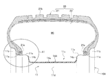
- FIG. 1 is a partial front cross-sectional view showing a major part of a vehicle wheel on which a tire is mounted according to a first embodiment of the present invention, and showing a cross section of a heat-insulation rubber attached on a rim outer circumference surface and that of a tire;
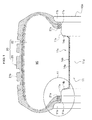
- FIG. 2 is an enlarged view of a part A 1 in FIG. 1 ;
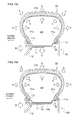
- FIG. 3A is a perspective view showing an external appearance of the heat-insulation rubber formed into a ring shape, and showing an example of heat-insulation rubber so formed as to gradually reduce a thickness toward an end;
- FIG. 3B is a perspective view showing an external appearance of the heat-insulation rubber formed into a ring shape, and showing an example of heat-insulation rubber so formed as to have a uniform thickness;
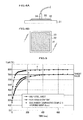
- FIG. 4A is a diagram explaining a test method when the heat insulating property of a test piece of the heat-insulation rubber was examined, where it has a top view with the test piece being mounted;
- FIG. 4B is a diagram explaining the test method when the heat insulating property of the test piece of the heat-insulation rubber was examined, where it has a top view with the test piece being mounted;
- FIG. 5 is an explanatory diagram for a temperature measurement when measurement was made through the test method shown in FIGS. 4A and 4B ;
- FIG. 6 is an explanatory diagram for a test result of a test piece of the heat-insulation rubber
- FIG. 7A shows a heat transfer path from a tire air chamber in running, and is an explanatory diagram for a case of a vehicle wheel having no heat-insulation rubber as a comparative example
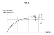
- FIG. 8 is an explanatory diagram for a temporal transition of a temperature at a tread portion of a tire after a vehicle starts running;
- FIG. 9 is a diagram showing how an end of the heat-insulation rubber is hardly caught when a bead portion of a tire is fallen into a well of a rim.
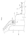
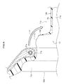
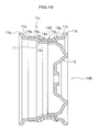
- FIG. 10 is an explanatory diagram for a cross-section shape of a heat-insulation rubber which is formed so as to match the contour of a rim outer circumference surface in a rim width direction and which is attached to a vehicle wheel according to a second embodiment.
- a vehicle wheel of the first embodiment will be explained with reference to FIGS. 1 , 2 , 3 A, and 3 B.
- FIG. 1 is a partial front cross-sectional view showing a major part of a vehicle wheel on which a vehicular tire is mounted according to the first embodiment of the present invention, and showing a cross section of a heat-insulation rubber attached on a rim outer circumference surface and that of a tire.
- FIG. 2 is an enlarged view of a part A 1 in FIG. 1 .
- FIG. 3A is a perspective view showing an external appearance of the heat-insulation rubber formed in a ring shape, and showing an illustrative heat-insulation rubber so formed as to gradually reduce a thickness toward an end.
- FIG. 3B is a perspective view showing an external appearance of the heat-insulation rubber formed in a ring shape, and showing an illustrative heat-insulation rubber so formed as to have a uniform thickness.
- a vehicle wheel 10 A includes a rim 11 for attaching a tire 20 thereto, and a disk (not shown) for coupling the rim 11 to a hub (not shown).
- the rim 11 has bead seating portions 11 a , 11 a formed at both ends thereof in a wheel width direction, rim flange portions 11 b , 11 b bent in a letter L shape from respective bead seating portions 11 a , 11 a toward an exterior of a wheel radial direction, and a well portion 11 c hollowed inwardly of the wheel radial direction between the bead seating portions 11 a , 11 a .
- the vehicle wheel 10 A also has hump portions 11 e , 11 e rising outwardly of the wheel radial direction ahead of portions where the bead seating portions 11 a , 11 a are hollowed into the well portion 11 c.
- a tire air chamber MC which is an annular sealed space is formed between an outer circumference surface 11 d of the rim 11 (a rim outer circumference surface) and an inner circumference surface of the tire 20 .
- reference numeral 21 denotes a tire main body
- reference numeral 22 denotes an inner liner
- reference numeral 21 b denotes a tread part.
- the well portion 11 c is provided in order to cause the bead portions 21 a , 21 a of the tire 20 to fall in the well portion 11 c at the time of rim fitting when the tire 20 is fitted to the rim 11 .
- the disk is so formed as to be continuous from an end of the rim 11 at a vehicle external side toward the internal side of the wheel radial direction.
- the rim 11 and the disk are both formed of, for example, a lightweight and high-strength material, such as an aluminum alloy or a magnesium alloy.
- the material is not limited to the foregoing one, and the rim 11 and the disk both may be formed of steel or the like. Also, the vehicle wheel 10 A may be a spoke-type wheel.
- An undercoat layer (not shown) which is a clear paint with a thickness of 5 to 40 ⁇ m is formed on the whole outer circumference surface 11 d of the rim 11 including the bead seating portion 11 a , the rim flange portion 11 b , the well portion 11 c , and the hump portion 11 e .
- the undercoat layer is formed in order to increase the corrosion resistance of the outer circumference surface 11 d of the rim 11 and to improve a close-contact condition of the bead portion 21 a with the outer circumference surface 11 d , and, a urethane-based, epoxy-based, acryl-based, or fluorine-based paint material having low heat conductivity or a blend thereof is desirable for the undercoat layer. Examples of such painting are electrodeposition coating and powder coating.
- a heat-insulation rubber 14 A is heated beforehand by a metal molding technique and formed into a ring shape by three-dimensional shaping is stretched up to a diameter larger than the rim flange portion 11 b by an attachment apparatus, and is attached on the outer circumference surface 11 d of the well portion 11 c .
- the heat-insulation rubber 14 A formed in a ring shape has, as shown in FIG. 2 , a basal part 14 a which corresponds to the flat part of the well portion 11 c and which has a predetermined thickness, e.g., 2 mm in an attached condition.
- the heat-insulation rubber 14 A also has end parts 14 b , 14 b which are located in the vicinity of respective hump portions 11 e , 11 e and each of which has a cross section in the rim width direction formed into a shape of which thickness gradually decreases from the thickness of 2 mm toward the external side of the rim width direction (hereinafter, this shape is referred to as a “taper shape”). It is desirable that the leading end of the end part 14 b should have a thickness of equal to or less than 0.5 mm.
- a bond e.g., an epoxy-based bond is applied to such outer circumference surface 11 d up to portions which reach respective hump portions 11 e , 11 e , and at which respective end parts 14 b , 14 b are correspondingly located.
- the heat-insulation rubber can fit the rim outer circumference shape across the well portion 11 c to the hump portion 11 e as a heat-insulation rubber 14 B itself can stretch, so that the heat-insulation rubber may be a heat-insulation rubber 14 B formed in a simple ring shape as shown in FIG. 3B .
- an attachment apparatus (not shown) which mounts the heat-insulation rubbers 14 A, 14 B formed in a ring shape beforehand on the outer circumference surface 11 d of the rim 11 for the case of the heat-insulation rubber 14 A as an example.
- the same is true of the case of the heat-insulation rubber 14 B.
- a difference between the heat-insulation rubber 14 A and the heat-insulation rubber 14 B is just an inner circumferential shape of an inner circumference surface of the attachment apparatus to be discussed later.
- the attachment apparatus has 16 inner-circumference-surface pieces formed in an inner-circumference-surface shape acquired by dividing the outer circumference surface of the heat-insulation rubber 14 A by a predetermined partial circumferential length, e.g., divided equally into 16 pieces.
- Each inner-circumference-surface piece is independently movable inwardly and outwardly of the radial direction, and air can be suctioned from the inner-circumference-surface side of the inner-circumference-surface pieces.
- the attachment apparatus first reduces a diameter of the inner-circumference-surface pieces until individual inner-circumference-surface pieces contact the outer circumference surface of the heat-insulation rubber 14 A, and suctions air through individual inner-circumference-surface pieces to vacuum-suction the heat-insulation rubber 14 A.
- individual inner-circumference-surface pieces are evenly moved outwardly of the radial direction while continuing vacuum-suctioning so that the inner diameter of the heat-insulation rubber 14 A becomes larger than the outer diameter of the rim flange portion 11 b .
- the attachment apparatus is caused to go over the rim flange portion 11 b in an axial direction, and the individual inner-circumference-surface pieces are evenly shrunk inwardly of the radial direction with a position in the axial direction being maintained so as to be aligned relative to the well portion 11 c to which the bond is applied.
- each inner-circumference-surface piece has the inner circumference surface which corresponds to the outer circumference surface of the heat-insulation rubber 14 A shown in FIG. 3A and which has a partial circumferential length, the end part 14 b can be surely pressed against the rising part reaching the hump portion 11 e of the rim 11 , and can be tightly bonded thereto.
- An example of the rubber material for the heat-insulation rubber 14 A, 14 B is a butyl rubber (Isobutylene Isoprene Rubber: IIR). This material is often used as an inner liner 22 on the inner surface of the tire 20 , and has a characteristic that the gas permeability is extremely little. Also, another example of the rubber material for the heat-insulation rubber 14 A, 14 B is a mixture of a butyl rubber with an ethylene propylene rubber (EPDM) that has good weather resistance.
- EPDM ethylene propylene rubber
- both butyl rubber and ethylene propylene rubber have low heat conductivity, are each a rubber material as it is which has good heat insulation property, and can be directly used as the heat-insulation rubber 14 A, 14 B.
- FIGS. 4A and 4B are diagrams for explaining a test method for examining the heat insulation property of a piece of the heat-insulation rubber, where FIG. 4A is a side view and FIG. 4B is a top view with the test piece being mounted.
- the inventors of the present invention additionally mixed such a material with FEF (fast extrusion furnace) class carbon black, a process oil, stearin acid, zinc oxide, sulfur, and a vulcanizing accelerator, and in order to improve the heat-insulation performance, further mixed and kneaded hollow particles, such as silica-alumina balloons (hollow particles formed of inorganic materials), ceramics balloons (hollow particles formed of ceramics), and shirasu balloons (hollow particles formed of “shirasu” that is volcanic ash), or a foaming agent to produce pieces of the heat-insulation rubber.
- FEF fast extrusion furnace
- FEF class is a quality level depending on a production technique
- FEF means a fast extrusion furnace
- the whole heat-insulation rubber is heated after mixed and kneaded, and then a gas is produced from the foaming agent to form gas bubbles in the heat-insulation rubber, thereby improving the heat-insulation performance.
- a foaming agent of a type that substantially exhausts all gases producible from the foaming agent when maintained at a predetermined temperature for a certain time period is desirable from the standpoint of the productivity of the heat-insulation rubber.
- a process of causing the foaming agent to produce a gas to produce gas bubbles in the heat-insulation rubber is carried out simultaneously with a process of heating the heat-insulation rubber through the foregoing metal molding to three-dimensionally shape the heat-insulation rubber 14 A.
- the inventors of the present invention mounted an SPCC (Steel Plate Cold Commercial) steel sheet (cold-rolled steel sheet) 32 of 200 mm by 200 mm square with a thickness of 2 mm replicating the rim 11 on an isothermal temperature adjusting hot plate 31 that had a surface temperature set to 80° C. in a closely attached manner.
- SPCC Step Plate Cold Commercial steel sheet
- the inventors of the present invention mounted a test piece 33 of the heat-insulation rubber in a predetermined rectangular shape with a thickness of 2 mm on the SPCC steel sheet 32 in a closely attached manner and measured a temperature change of an upper surface of the test piece 33 of the heat-insulation rubber for ten minutes by a contact-type temperature sensor, and examined the heat-insulation property of the test piece 33 of the heat-insulation rubber from a saturation temperature.
- FIG. 5 is an explanatory diagram for a temperature measurement when measurement was made through the test method shown in FIGS. 4A and 4B .
- a temperature reached substantially 80° C. after ten minutes.
- a comparison target for developing the material mixing for the heat-insulation rubber was the heat-insulation performance of a heat-insulation paint “GAINA” (registered trademark) with a thickness of 2 mm indicated by a curve c. Note that the heat-insulation paint “GAINA” has a heat-insulation performance of approximately 0.03 W/mK.
- a curve b indicates a case in which 6 Phr of a foaming agent was mixed to a base material that was a first comparative example shown in FIG. 6 .
- Phr Per Hundred Rubber, i.e., a notation indicating parts by weight (pts. wt) that is a value of a weight of an additive agent relative to 100 weight of a rubber material. This notation makes it easier to understand pts. wt of an additive agent than an expression of an amount of an additive agent in a weight ratio relative to the whole additive agent even though the number of kinds of additive agent increases.
- Total Phr in FIG. 6 is an addition expression of 100 weight of rubber with pts. wt of all other additive agents.
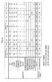
- FIG. 6 is an explanatory diagram showing a test result of a test piece of the heat-insulation rubber.
- a heat-insulation rubber which had a butyl rubber of 100 weight as a rubber material mixed with an FEF class black carbon of 60 pts. wt, a process oil of 10 pts. wt, stearic acid of 1 pts. wt, a zinc oxide of 5 pts. wt, sulfur of 1 pts. wt, and a vulcanizing accelerator of 1 pts. wt, and which had a Total Phr of 178.0 was taken as a first base rubber.
- a heat transmission coefficient (W/m 2 K) when the first comparative example was examined as the test piece in FIGS. 4A and 4B was taken as 100% as a base.
- Respective heat transmission coefficients (W/m 2 K) when first to tenth examples and a second comparative example were tested as a test piece in FIGS. 4A and 4B were shown in a percent expression in “heat transference (%)” in “test result field” in FIG. 6 . The lower the value of the heat transference is, the higher the heat-insulation performance is.
- a first example was the first base rubber of the first comparative example added with silica-alumina balloons of 50 pts. wt, had Total Phr of 228.0, and had heat transference of 88%.
- a second example was the first base rubber of the first comparative example added with ceramics balloons of 50 pts. wt, had Total Phr of 228.0, and had heat transference of 91%.
- a third example was the first base rubber of the first comparative example added with shirasu balloons of 50 pts. wt, had Total Phr of 228.0, and had heat transference of 87%.
- a fourth example was the first base rubber of the first comparative example added with a foaming agent of 4 pts.
- a fifth example was the first base rubber of the first comparative example added with a foaming agent of 8 pts. wt, had Total Phr of 186.0, and had heat transference of 53%.
- the second comparative example was a heat-insulation rubber as second base rubber which had, as rubber materials, 50 weight of a butyl rubber and 50 weight of an ethylene propylene rubber having good antiweatherbility that were mixed with the FEF class black carbon of 60 pts. wt, a process oil of 10 pts. wt, a stearic acid of 1 pts. wt, a zinc oxide of 5 pts. wt, sulfur of 1 pts. wt, and a vulcanizing accelerator of 1 pts. wt, had Total Phr of 178.0, and had heat transference of 99%.
- a sixth example was the second base rubber of the second comparative example added with silica-alumina balloons of 50 pts. wt, had Total Phr of 228.0, and had heat transference of 86%.
- a seventh example was the second base rubber of the second comparative example added with ceramics balloons of 50 pts. wt, had Total Phr of 228.0, and had heat transference of 87%.
- An eighth example was the second base rubber of the second comparative example added with shirasu balloons of 50 pts. wt, had Total Phr of 228.0, and had heat transference of 86%.
- a ninth example was the second base rubber of the second comparative example added with a foaming agent of 4 pts.
- wt had Total Phr of 182.0, and had heat transference of 74%.
- a tenth example was the second base rubber of the second comparative example added with a foaming agent of 8 pts. wt, had Total Phr of 186.0, and had heat transference of 55%.
- a butyl rubber (IIR) was a butyl rubber “BROMOBUTYL3344” (registered trademark) of Japan Butyl Co., Ltd.
- an ethylene propylene rubber was an ethylene propylene rubber “ESPRENE301A” (registered trademark) of Sumitomo Chemical Co., Ltd
- a vulcanizing accelerator was “NOCCELER-NS-P” of Ouchi Shinko Chemical Industrial Co., Ltd., which was N-ter-butyl-2-benzothiazolylsulfenicamide
- silica-alumina balloon was “Cenolite” (registered trademark) of Tomoe Engineering Co., Ltd.
- a ceramics balloon was “E-SPHERES” (registered trademark) of Taiheiyo Cement Corporation
- a shirasu balloon was “Winlite9011” (registered trademark) of Izichi Chemical Industry Co
- isolated gas bubbles Gas bubbles having a wall between adjoining non-successive gas bubbles with a thickness of equal to thicker than the predetermined thickness is referred to as “isolated gas bubbles”.
- a heat-insulation rubber which is light-weighted and has a better heat-insulation property can be obtained if the foaming agent is used rather than using the hollow particles, such as the silica-alumina balloons, the ceramics balloons, or the shirasu balloons. Also, when the bead portion 21 a (see FIG. 1 ) is fallen on the heat-insulation rubber 14 A (see FIG. 1 ) at the time of fitting or removal of the tire 20 , the gas bubbles formed in the heat-insulation rubber by the foaming agent do not break down.
- the foams are each fully filled with the gas, when the bead portion 21 a is removed, even squashed gas bubbles can recover to a normal condition by the elastic force of the heat-insulation rubber, so that the heat-insulation performance is not likely to change.
- the hollow particles such as the silica-alumina balloons, the ceramics balloons, or the shirasu balloons
- the hollow particles when the bead portion 21 a is fallen on the heat-insulation rubber at the time of fitting or removal of the tire 20 , the hollow particles are damaged, and the heat-insulation property may change. Therefore, it is desirable that such hollow particles should have a small diameter, and should be caused to have a sufficient strength.
- FIGS. 7A and 7B show heat transfer paths from the tire air chamber in running, where FIG. 7A is an explanatory diagram in a case of a vehicle wheel having no heat-insulation rubber as a comparative example, and FIG. 7B is an explanatory diagram in a case of a vehicle wheel having the heat-insulation rubber according to the first embodiment.
- FIG. 8 is an explanatory diagram for a temporal transition of a temperature at the tread portion of a tire after a vehicle starts running.
- FIGS. 7A and 7B also, an under-coat layer which is a clear paint is omitted.
- the tread portion 21 b starts generating heat by a friction with a road surface, and the shoulder portions of the tire 20 , the side portions thereof, etc., generate heat due to hysteresis loss by a rolling friction or are heated by heat conduction.
- the heat-dissipation paths (1) and (2) are common in the case of the vehicle wheel 10 , but regarding the path (3), the heat-insulation rubber 14 A suppresses any heat transfer from the tire air chamber MC to the rim 11 as is indicated by an arrow C R , and the high heat-insulation performance is accomplished, so that the temperature at the tire air chamber MC increases in comparison with the case of the vehicle wheel 10 which is the comparative example.
- an axis of ordinate indicates a temperature of the tread portion 21 b of the tire 20 and an axis of abscissa indicates an elapsed time after the vehicle starts running.
- a curve x 1 indicates a comparative example having no heat-insulation rubber 14 A
- a curve x 2 indicates another comparative example having a layer of the heat-insulation paint (thickness: 2 mm)
- a curve x 3 indicates a case with the heat-insulation rubber 14 A of the first embodiment (thickness: 2 mm).
- the condition of the heat-insulation rubber 14 A was the composition represented by the fifth example in the table of FIG. 6 , and a heat-insulation performance of 0.03 W/m ⁇ K was accomplished.
- the temperature of the tread portion of the tire can be set to be 2 to 3° C. higher than the curve x 1 of the comparative example.
- the rolling resistance can be reduced by what corresponds to such higher temperature setting, and the fuel economy improves by approximately 1% in the LA-4 mode (an urban zone running mode) which is used for an automotive fuel economy test in U.S.A.
- heat-insulation paint of the curve x 2 of the comparative example was the foregoing heat-insulation paint “GAINA”. It becomes clear that this heat-insulation paint and the heat-insulation rubber 14 A of the first embodiment can obtain substantially the same heat-insulation property.
- the heat transference (%) in the foregoing evaluation result was 55% with respect to 53% which was the heat transference of the fifth example, so that there is substantially no difference therebetween, and the weather resistance was improved.
- FIG. 9 is a diagram for explaining how the end part of the heat-insulation rubber is hardly caught when the bead portion of the tire is fallen onto the well portion of the rim.
- the heat-insulation rubber 14 A formed into a ring shape has a base 14 a which corresponds to the flat part of the well portion 11 c and which has a thickness of 2 mm when attached.
- Each of the end parts 14 b , 14 b near the hump portions 11 e , 11 e , respectively, located outwardly of the rim width direction has a cross section in the rim width direction in which a thickness thereof decreases from 2 mm toward the external side of the rim width direction in an attached condition.
- the heat-insulation layer in comparison with a case in which a heat-insulation paint that forms a heat-shield/heat-insulation layer is applied like the foregoing prior art disclosed in JP2009-73247A, the heat-insulation layer can be formed on the outer circumference surface 11 d of the rim 11 with a uniform predetermined thickness, and a target heat-insulation performance can be surely accomplished. As shown in FIG.
- the heat-insulation rubber 14 A of the first embodiment the heat-insulation rubber 14 A formed into a ring shape through a metal molding technique while being heated beforehand can be mechanically attached, at a rim-width-direction position on the outer circumference surface 11 d of the well portion 11 c on which a bond is applied as explained in the foregoing attachment method of the heat-insulation rubber. Accordingly, the workability is good, and the thickness of the heat-insulation rubber 14 A after attachment can be easily set to a predetermined thickness relative to not only the rim width direction of the vehicle wheel 10 but also the circumferential direction. Also, the contractive force of the heat-insulation rubber 14 A can be utilized as the fixing force to the outer circumference surface 11 d.
- the heat-insulation rubber 14 A formed in the ring shape has the end parts 14 b , 14 b which are located near the hump portions 11 e , 11 e , respectively, located outwardly in the rim width direction and which have respective cross sections each gradually reducing its thickness from a thickness of 2 mm toward the external side of the rim width direction in an attached condition. Accordingly, the possibility that the bead portion 21 a catches the end part 14 b of the heat-insulation rubber 14 A and peels or damages the heat-insulation rubber 14 A can be reduced when the bead portion 21 a of the tire 20 is fallen onto the well portion 11 c of the rim 11 .
- the heat-insulation performance of the heat-insulation rubber can be further improved and such a heat-insulation rubber can be light-weighted when the foaming agent is used like the fourth, fifth, ninth and tenth examples.
- the end part 14 b of the heat-insulation rubber 14 A is formed so as to have a tapered cross section in the rim width direction at the time of metal molding.
- a cross section in the rim width direction may be formed in a tapered shape after metal molding.
- the same structural elements as those of the first embodiment will be denoted by the same reference numerals, and a duplicated explanation will be omitted below.
- the difference of the vehicle wheel 10 B of the second embodiment from the vehicle wheel 10 A of the first embodiment is in the outer circumferential shape of the well portion 11 c .
- the vehicle wheel 10 B has substantially no hump portions 11 e , 11 e shown in FIG. 1 , and the outer circumference surface 11 d of the well portion 11 c has a cross section in the rim width direction changing in that direction.
- a ring-shaped heat-insulation rubber 14 C has an inner circumference side and an outer circumference side both changing in the rim width direction, and is formed by three-dimensional metal molding so as to maintain a predetermined thickness, e.g., 2 mm.
- end parts 14 b A , 14 b B are also formed.
- the thickness of a base 14 a A adjoining to the end part 14 b A at the outer side of a vehicle width in the rim width direction, the thickness of a center base 14 a in the rim width direction, and the thickness of a base 14 a B adjoining to the end part 14 b B at the internal side of the vehicle width in the rim width direction differ from one another.
- the base 14 a has the greatest thickness, and the base 14 a A has a greater thickness than that of the base 14 a B .
- This configuration is provided because the shape from the bead seating portion 11 a to the well portion 11 c in the vehicle wheel 10 B differs between the outer side of the vehicle width and the inner side of the vehicle width. In addition, this configuration is provided to prevent the end part 14 b B and the base 14 a B from being caught and turned, from being damaged and from being broken when the bead portion 21 a of the internal side of the vehicle width is fallen onto the well portion 11 c.
- the heat-insulation rubber 14 C can be caused to closely attached to the outer circumference surface 11 d of the vehicle wheel having the outer circumference surface 11 d of the rim 11 of the well portion 11 c normally not flat. As a result, it is possible to suppress any heat transfer to the rim 11 from a portion of the outer circumference surface 11 d where air in the tire air chamber MC contacts.
Landscapes
- Engineering & Computer Science (AREA)
- Mechanical Engineering (AREA)
- Tires In General (AREA)
- Moulds For Moulding Plastics Or The Like (AREA)
- Heating, Cooling, Or Curing Plastics Or The Like In General (AREA)
Abstract
Description
- This application claims the foreign priority benefit under Title 35, United States Code, §119(a)-(d) of Japanese Patent Application No. 2009-206549, filed on Sep. 8, 2009 in the Japan Patent Office, the disclosure of which is herein incorporated by reference in its entirety.
- 1. Field of the Invention
- The present invention relates to a vehicle wheel, and more particularly, to a vehicle wheel capable of reducing a rolling resistance of a tire attached to a wheel.
- 2. Description of the Related Art
- Conventionally, it is known that rolling resistance decreases as a temperature of a tire of a vehicle rises. High temperature of the tire improves a gas mileage performance of the vehicle, and a gripping force at a tire tread portion is also improved. JP 2009-73247A discloses a technology of applying a heat-shield/heat-insulation coating having a thickness of 50 to 500 μm on a rim outer circumference surface other than a bead seating portion of the rim outer circumference surface and a rim flange portion thereof to form heat-shield/heat-insulation layer (see, in particular,
FIG. 1 ). - According to the technology disclosed in JP2009-73247A, however, as the heat-shield/heat-insulation coating is applied on the rim outer circumference surface, it is necessary to mask the bead seating portion and the rim flange portion before a heat-insulation paint is applied or to process a vehicle wheel while rotating the vehicle wheel in order to prevent the heat-insulation paint from dripping in a painting/drying process and to obtain a uniform thickness, resulting in poor productivity. Also, because the paint is a liquid, it is difficult to control a layer thickness of such a paint to be uniform to secure quality.
- The present invention can provide a vehicle wheel which can reduce a rolling resistance by increasing a tire temperature with a simple structure.
- A first aspect of the present invention provides a vehicle wheel comprising a heat-insulation rubber that covers a portion of a rim outer circumference surface where air in a tire air chamber contacts.
- According to the first aspect of the present invention, in comparison with a case in which a heat-insulation paint which forms a heat-shield/heat-insulation layer is painted like the prior art disclosed in JP 2009-73247A, since the heat-insulation rubber can be formed on the rim outer circumference surface uniformly at a predetermined thickness, a target heat-insulation performance can be surely accomplished. When a tire temperature rises due to heat originating from a friction with a road surface or hysteresis loss of the interior of a tire, the heat is transferred to air in the tire air chamber, and the temperature of the air in the tire air chamber rises, it is possible to suppress any dissipation of heat to the atmosphere through a rim and a disc via a portion where the air in the tire air chamber contacts the rim outer circumference surface of the vehicle wheel.
- A second aspect of the present invention provides the vehicle wheel based on the first aspect, wherein the heat-insulation rubber is formed into a ring shape and is fitted onto the portion of the rim outer circumference surface where the air in the tire air chamber contacts.
- According to the second aspect of the present invention, as the heat-insulation rubber formed into a ring shape is used, a process of pasting end portions of a tabular heat-insulation rubber to form the tabular heat-insulation rubber into a ring shape can be omitted. Moreover, the heat-insulation rubber formed into the ring shape can be stretched over the diameter of the rim flange portion of the rim by an attachment apparatus, and can be easily attached on the outer circumference surface of a well portion, and, the productivity of the heat-insulation layer becomes better than heat-insulation paints. Moreover, the contractive force of the heat-insulation rubber can be utilized as fixing force to the rim outer circumference surface.
- A third aspect of the present invention provides the vehicle wheel based on the first aspect, wherein the heat-insulation rubber is shaped so as to match a cross-sectional contour of the rim outer circumference surface in a rim width direction.
- According to the third aspect of the present invention, because the heat-insulation rubber is shaped so as to match the cross-sectional contour of the rim outer circumference surface in the rim width direction, the heat-insulation rubber can be caused to closely contact the rim outer circumference surface of the vehicle wheel having the rim outer circumference surface of the well portion normally not flat. As a result, it is possible to suppress any heat transfer to the rim from a portion of the rim outer circumference surface where air in the tire air chamber contacts.
- A fourth aspect of the present invention provides the vehicle wheel based on the first aspect, wherein a part of the heat-insulation rubber located outside, a well portion on the rim outer circumference surface in a rim width direction has a thickness which gradually decreases as a location at the part goes toward an end part of the heat-insulation rubber, and the end part of the heat-insulation rubber extends up to a hump portion on the rim outer circumference surface.
- According to the fourth aspect of the present invention, it is possible to reduce the possibility that the bead portion of a tire catches the end part of the heat-insulation rubber and peels or damages the heat-insulation rubber when the bead portion is fallen onto the well portion of the rim.
- A fifth aspect of the present invention provides the vehicle wheel based on the second aspect, wherein the heat-insulation rubber shaped into the ring is produced by a production method comprising:
- mixing a predetermined amount of a foaming agent in advance with a rubber material for the heat-insulation rubber to have a composition for generating isolated gas bubbles, before the rubber material is shaped into the ring;
- kneading the mixture; and
- heating when shaping the kneaded mixture into the ring to cause the foaming agent to foam to produce the heat-insulation rubber including the isolated gas bubbles therein.
- According to the fifth aspect of the present invention, isolated gas bubbles are distributed in the heat-insulation rubber, so that any heat transfer to the rim from the tire air chamber via the heat-insulation rubber can be extremely reduced. In particular, as the additive amount of the foam agent is set to a predetermined amount which does not produce any substantially successive foams or successive foams in the heat-insulation rubber, any heat transfer by the convection flow of gases in the substantially successive foams or in the successive foams is suppressed, thereby extremely reducing any heat transfer to the rim from the tire air chamber via the heat-insulation rubber.
- According to the present invention, a tire temperature when a vehicle is running can be increased, a rolling resistance can be reduced, and the fuel economy can be improved.
-
FIG. 1 is a partial front cross-sectional view showing a major part of a vehicle wheel on which a tire is mounted according to a first embodiment of the present invention, and showing a cross section of a heat-insulation rubber attached on a rim outer circumference surface and that of a tire; -
FIG. 2 is an enlarged view of a part A1 inFIG. 1 ; -
FIG. 3A is a perspective view showing an external appearance of the heat-insulation rubber formed into a ring shape, and showing an example of heat-insulation rubber so formed as to gradually reduce a thickness toward an end; -
FIG. 3B is a perspective view showing an external appearance of the heat-insulation rubber formed into a ring shape, and showing an example of heat-insulation rubber so formed as to have a uniform thickness; -
FIG. 4A is a diagram explaining a test method when the heat insulating property of a test piece of the heat-insulation rubber was examined, where it has a top view with the test piece being mounted; -
FIG. 4B is a diagram explaining the test method when the heat insulating property of the test piece of the heat-insulation rubber was examined, where it has a top view with the test piece being mounted; -
FIG. 5 is an explanatory diagram for a temperature measurement when measurement was made through the test method shown inFIGS. 4A and 4B ; -
FIG. 6 is an explanatory diagram for a test result of a test piece of the heat-insulation rubber; -
FIG. 7A shows a heat transfer path from a tire air chamber in running, and is an explanatory diagram for a case of a vehicle wheel having no heat-insulation rubber as a comparative example; -
FIG. 7B shows a heat transfer path from a tire air chamber in running, and is an explanatory diagram for a case of a vehicle wheel having the heat-insulation rubber according to the first embodiment; -
FIG. 8 is an explanatory diagram for a temporal transition of a temperature at a tread portion of a tire after a vehicle starts running; -
FIG. 9 is a diagram showing how an end of the heat-insulation rubber is hardly caught when a bead portion of a tire is fallen into a well of a rim; and -
FIG. 10 is an explanatory diagram for a cross-section shape of a heat-insulation rubber which is formed so as to match the contour of a rim outer circumference surface in a rim width direction and which is attached to a vehicle wheel according to a second embodiment. - A detailed explanation will be given of a vehicle wheel according to a first embodiment of the present invention with reference to accompanying drawings.
- A vehicle wheel of the first embodiment will be explained with reference to
FIGS. 1 , 2, 3A, and 3B. -
FIG. 1 is a partial front cross-sectional view showing a major part of a vehicle wheel on which a vehicular tire is mounted according to the first embodiment of the present invention, and showing a cross section of a heat-insulation rubber attached on a rim outer circumference surface and that of a tire.FIG. 2 is an enlarged view of a part A1 inFIG. 1 .FIG. 3A is a perspective view showing an external appearance of the heat-insulation rubber formed in a ring shape, and showing an illustrative heat-insulation rubber so formed as to gradually reduce a thickness toward an end.FIG. 3B is a perspective view showing an external appearance of the heat-insulation rubber formed in a ring shape, and showing an illustrative heat-insulation rubber so formed as to have a uniform thickness. - As shown in
FIG. 1 , avehicle wheel 10A includes arim 11 for attaching atire 20 thereto, and a disk (not shown) for coupling therim 11 to a hub (not shown). - As shown in
FIG. 1 , therim 11 hasbead seating portions rim flange portions bead seating portions well portion 11 c hollowed inwardly of the wheel radial direction between thebead seating portions vehicle wheel 10A also hashump portions bead seating portions well portion 11 c. -
Bead portions 21 a of thetire 20 are mounted on respectivebead seating portions 11 a. Accordingly, a tire air chamber MC which is an annular sealed space is formed between anouter circumference surface 11 d of the rim 11 (a rim outer circumference surface) and an inner circumference surface of thetire 20. - Note that regarding the
tire 20,reference numeral 21 denotes a tire main body,reference numeral 22 denotes an inner liner, andreference numeral 21 b denotes a tread part. - The
well portion 11 c is provided in order to cause thebead portions tire 20 to fall in thewell portion 11 c at the time of rim fitting when thetire 20 is fitted to therim 11. - The disk is so formed as to be continuous from an end of the
rim 11 at a vehicle external side toward the internal side of the wheel radial direction. Therim 11 and the disk are both formed of, for example, a lightweight and high-strength material, such as an aluminum alloy or a magnesium alloy. - The material is not limited to the foregoing one, and the
rim 11 and the disk both may be formed of steel or the like. Also, thevehicle wheel 10A may be a spoke-type wheel. - An undercoat layer (not shown) which is a clear paint with a thickness of 5 to 40 μm is formed on the whole
outer circumference surface 11 d of therim 11 including thebead seating portion 11 a, therim flange portion 11 b, thewell portion 11 c, and thehump portion 11 e. The undercoat layer is formed in order to increase the corrosion resistance of theouter circumference surface 11 d of therim 11 and to improve a close-contact condition of thebead portion 21 a with theouter circumference surface 11 d, and, a urethane-based, epoxy-based, acryl-based, or fluorine-based paint material having low heat conductivity or a blend thereof is desirable for the undercoat layer. Examples of such painting are electrodeposition coating and powder coating. - <Heat-Insulation Rubber>
- As shown in
FIG. 3A , a heat-insulation rubber 14A is heated beforehand by a metal molding technique and formed into a ring shape by three-dimensional shaping is stretched up to a diameter larger than therim flange portion 11 b by an attachment apparatus, and is attached on theouter circumference surface 11 d of thewell portion 11 c. At this time, the heat-insulation rubber 14A formed in a ring shape has, as shown inFIG. 2 , abasal part 14 a which corresponds to the flat part of thewell portion 11 c and which has a predetermined thickness, e.g., 2 mm in an attached condition. The heat-insulation rubber 14A also hasend parts respective hump portions end part 14 b should have a thickness of equal to or less than 0.5 mm. - As a result, it is possible to cover not only the flat part of the
well portion 11 c but also the rising parts of thewell portion 11 c in the vicinity ofrespective hump portions insulation rubber 14A. - Note that before the heat-
insulation rubber 14A is attached on theouter circumference surface 11 d of thewell portion 11 c inwardly of theouter circumference surface 11 d of therim 11, a bond, e.g., an epoxy-based bond is applied to suchouter circumference surface 11 d up to portions which reachrespective hump portions respective end parts - When the rising parts of the
well portion 11 c located at both ends near thehump portions well portion 11 c to thehump portion 11 e as a heat-insulation rubber 14B itself can stretch, so that the heat-insulation rubber may be a heat-insulation rubber 14B formed in a simple ring shape as shown inFIG. 3B . - <Method of Mounting Heat-Insulation Rubber>
- An explanation will be given of an attachment apparatus (not shown) which mounts the heat-
insulation rubbers outer circumference surface 11 d of therim 11 for the case of the heat-insulation rubber 14A as an example. The same is true of the case of the heat-insulation rubber 14B. A difference between the heat-insulation rubber 14A and the heat-insulation rubber 14B is just an inner circumferential shape of an inner circumference surface of the attachment apparatus to be discussed later. The attachment apparatus has 16 inner-circumference-surface pieces formed in an inner-circumference-surface shape acquired by dividing the outer circumference surface of the heat-insulation rubber 14A by a predetermined partial circumferential length, e.g., divided equally into 16 pieces. Each inner-circumference-surface piece is independently movable inwardly and outwardly of the radial direction, and air can be suctioned from the inner-circumference-surface side of the inner-circumference-surface pieces. The attachment apparatus first reduces a diameter of the inner-circumference-surface pieces until individual inner-circumference-surface pieces contact the outer circumference surface of the heat-insulation rubber 14A, and suctions air through individual inner-circumference-surface pieces to vacuum-suction the heat-insulation rubber 14A. Also, individual inner-circumference-surface pieces are evenly moved outwardly of the radial direction while continuing vacuum-suctioning so that the inner diameter of the heat-insulation rubber 14A becomes larger than the outer diameter of therim flange portion 11 b. In this condition, the attachment apparatus is caused to go over therim flange portion 11 b in an axial direction, and the individual inner-circumference-surface pieces are evenly shrunk inwardly of the radial direction with a position in the axial direction being maintained so as to be aligned relative to thewell portion 11 c to which the bond is applied. Finally, air is blown in from individual inner-circumference-surface pieces while the heat-insulation rubber 14A is being lightly pressed against theouter circumference surface 11 d, and then the inner circumferential sides of respective inner-circumference-surface pieces and the outer circumference surface of the heat-insulation rubber 14A are separated from each other. - As each inner-circumference-surface piece has the inner circumference surface which corresponds to the outer circumference surface of the heat-
insulation rubber 14A shown inFIG. 3A and which has a partial circumferential length, theend part 14 b can be surely pressed against the rising part reaching thehump portion 11 e of therim 11, and can be tightly bonded thereto. - <Detailed Explanation for Heat-Insulation Rubber>
- Next, with reference to
FIGS. 4A to 6 , the heat-insulation rubbers - An example of the rubber material for the heat-
insulation rubber inner liner 22 on the inner surface of thetire 20, and has a characteristic that the gas permeability is extremely little. Also, another example of the rubber material for the heat-insulation rubber - Note that both butyl rubber and ethylene propylene rubber have low heat conductivity, are each a rubber material as it is which has good heat insulation property, and can be directly used as the heat-
insulation rubber -
FIGS. 4A and 4B are diagrams for explaining a test method for examining the heat insulation property of a piece of the heat-insulation rubber, whereFIG. 4A is a side view andFIG. 4B is a top view with the test piece being mounted. - Starting with a butyl rubber as a basic rubber material, as shown in
FIG. 6 , the inventors of the present invention additionally mixed such a material with FEF (fast extrusion furnace) class carbon black, a process oil, stearin acid, zinc oxide, sulfur, and a vulcanizing accelerator, and in order to improve the heat-insulation performance, further mixed and kneaded hollow particles, such as silica-alumina balloons (hollow particles formed of inorganic materials), ceramics balloons (hollow particles formed of ceramics), and shirasu balloons (hollow particles formed of “shirasu” that is volcanic ash), or a foaming agent to produce pieces of the heat-insulation rubber. - Note that a term FEF class is a quality level depending on a production technique, and a term FEF means a fast extrusion furnace.
- In the case of the foaming agent, the whole heat-insulation rubber is heated after mixed and kneaded, and then a gas is produced from the foaming agent to form gas bubbles in the heat-insulation rubber, thereby improving the heat-insulation performance. As such a foaming agent, a foaming agent of a type that substantially exhausts all gases producible from the foaming agent when maintained at a predetermined temperature for a certain time period is desirable from the standpoint of the productivity of the heat-insulation rubber.
- Incidentally, it is preferable that a process of causing the foaming agent to produce a gas to produce gas bubbles in the heat-insulation rubber is carried out simultaneously with a process of heating the heat-insulation rubber through the foregoing metal molding to three-dimensionally shape the heat-
insulation rubber 14A. - As shown in
FIGS. 4A and 4B , the inventors of the present invention mounted an SPCC (Steel Plate Cold Commercial) steel sheet (cold-rolled steel sheet) 32 of 200 mm by 200 mm square with a thickness of 2 mm replicating therim 11 on an isothermal temperature adjustinghot plate 31 that had a surface temperature set to 80° C. in a closely attached manner. Also, the inventors of the present invention mounted atest piece 33 of the heat-insulation rubber in a predetermined rectangular shape with a thickness of 2 mm on theSPCC steel sheet 32 in a closely attached manner and measured a temperature change of an upper surface of thetest piece 33 of the heat-insulation rubber for ten minutes by a contact-type temperature sensor, and examined the heat-insulation property of thetest piece 33 of the heat-insulation rubber from a saturation temperature. -
FIG. 5 is an explanatory diagram for a temperature measurement when measurement was made through the test method shown inFIGS. 4A and 4B . As is indicated by a curve a, in a case where only theSPCC steel sheet 32 is used, a temperature reached substantially 80° C. after ten minutes. A comparison target for developing the material mixing for the heat-insulation rubber was the heat-insulation performance of a heat-insulation paint “GAINA” (registered trademark) with a thickness of 2 mm indicated by a curve c. Note that the heat-insulation paint “GAINA” has a heat-insulation performance of approximately 0.03 W/mK. - A curve b indicates a case in which 6 Phr of a foaming agent was mixed to a base material that was a first comparative example shown in
FIG. 6 . - Note that a term Phr (mentioned as PHR in some cases) means Per Hundred Rubber, i.e., a notation indicating parts by weight (pts. wt) that is a value of a weight of an additive agent relative to 100 weight of a rubber material. This notation makes it easier to understand pts. wt of an additive agent than an expression of an amount of an additive agent in a weight ratio relative to the whole additive agent even though the number of kinds of additive agent increases. Note that a term Total Phr in
FIG. 6 is an addition expression of 100 weight of rubber with pts. wt of all other additive agents. -
FIG. 6 is an explanatory diagram showing a test result of a test piece of the heat-insulation rubber. As a first comparative example, a heat-insulation rubber which had a butyl rubber of 100 weight as a rubber material mixed with an FEF class black carbon of 60 pts. wt, a process oil of 10 pts. wt, stearic acid of 1 pts. wt, a zinc oxide of 5 pts. wt, sulfur of 1 pts. wt, and a vulcanizing accelerator of 1 pts. wt, and which had a Total Phr of 178.0 was taken as a first base rubber. A heat transmission coefficient (W/m2K) when the first comparative example was examined as the test piece inFIGS. 4A and 4B was taken as 100% as a base. Respective heat transmission coefficients (W/m2K) when first to tenth examples and a second comparative example were tested as a test piece inFIGS. 4A and 4B were shown in a percent expression in “heat transference (%)” in “test result field” inFIG. 6 . The lower the value of the heat transference is, the higher the heat-insulation performance is. - A first example was the first base rubber of the first comparative example added with silica-alumina balloons of 50 pts. wt, had Total Phr of 228.0, and had heat transference of 88%. A second example was the first base rubber of the first comparative example added with ceramics balloons of 50 pts. wt, had Total Phr of 228.0, and had heat transference of 91%. A third example was the first base rubber of the first comparative example added with shirasu balloons of 50 pts. wt, had Total Phr of 228.0, and had heat transference of 87%. A fourth example was the first base rubber of the first comparative example added with a foaming agent of 4 pts. wt, had Total Phr of 182.0, and had heat transference of 71%. A fifth example was the first base rubber of the first comparative example added with a foaming agent of 8 pts. wt, had Total Phr of 186.0, and had heat transference of 53%.
- The second comparative example was a heat-insulation rubber as second base rubber which had, as rubber materials, 50 weight of a butyl rubber and 50 weight of an ethylene propylene rubber having good antiweatherbility that were mixed with the FEF class black carbon of 60 pts. wt, a process oil of 10 pts. wt, a stearic acid of 1 pts. wt, a zinc oxide of 5 pts. wt, sulfur of 1 pts. wt, and a vulcanizing accelerator of 1 pts. wt, had Total Phr of 178.0, and had heat transference of 99%.
- A sixth example was the second base rubber of the second comparative example added with silica-alumina balloons of 50 pts. wt, had Total Phr of 228.0, and had heat transference of 86%. A seventh example was the second base rubber of the second comparative example added with ceramics balloons of 50 pts. wt, had Total Phr of 228.0, and had heat transference of 87%. An eighth example was the second base rubber of the second comparative example added with shirasu balloons of 50 pts. wt, had Total Phr of 228.0, and had heat transference of 86%. A ninth example was the second base rubber of the second comparative example added with a foaming agent of 4 pts. wt, had Total Phr of 182.0, and had heat transference of 74%. A tenth example was the second base rubber of the second comparative example added with a foaming agent of 8 pts. wt, had Total Phr of 186.0, and had heat transference of 55%.
- Note that specific names (registered trademarks) and manufacturers of composition elements used for evaluation in
FIG. 6 are as follows. A butyl rubber (IIR) was a butyl rubber “BROMOBUTYL3344” (registered trademark) of Japan Butyl Co., Ltd., an ethylene propylene rubber was an ethylene propylene rubber “ESPRENE301A” (registered trademark) of Sumitomo Chemical Co., Ltd, a vulcanizing accelerator was “NOCCELER-NS-P” of Ouchi Shinko Chemical Industrial Co., Ltd., which was N-ter-butyl-2-benzothiazolylsulfenicamide, silica-alumina balloon was “Cenolite” (registered trademark) of Tomoe Engineering Co., Ltd., a ceramics balloon was “E-SPHERES” (registered trademark) of Taiheiyo Cement Corporation, a shirasu balloon was “Winlite9011” (registered trademark) of Izichi Chemical Industry Co., Ltd., and a foaming agent was “ExellarQ” (registered trademark) of Eiwa Chemical Ind. Co., Ltd., which contains N,N′-dinitrosopentamethylenetetramine (DNPT) and azodicarboxylicamide (ADCA) as main constituents. - The reason why the percentage of the foaming agent in the fourth, fifth, ninth, and tenth examples was set to 4% or 8% was to study the heat-insulation effect of the heat-insulation rubber and a shape of a gas foam in a cut cross section of the heat-insulation rubber by changing the amount of foaming agent. It was found if the amount of the foaming agent is excessive, a wall between adjoining isolated produced gas bubbles becomes too thin and substantially successive gas bubbles are formed, or a large foam (successive gas bubbles) is formed, so that the heat-insulation effect is deteriorated by the convection flow of a gas in the foam. As a result, it was found, in order to form gas bubbles having a wall between adjoining non-successive gas bubbles with a thickness equal to or thicker than a predetermined thickness, pts. wt of 4 to 8 of the foaming agent is appropriate.
- Gas bubbles having a wall between adjoining non-successive gas bubbles with a thickness of equal to thicker than the predetermined thickness is referred to as “isolated gas bubbles”. A composition in which pts. wt of 4 to 8 of the foaming agent relative to 100 weight of the rubber material corresponds to “a composition for generating isolated gas bubbles”.
- As is clear from the result in
FIG. 6 , a heat-insulation rubber which is light-weighted and has a better heat-insulation property can be obtained if the foaming agent is used rather than using the hollow particles, such as the silica-alumina balloons, the ceramics balloons, or the shirasu balloons. Also, when thebead portion 21 a (seeFIG. 1 ) is fallen on the heat-insulation rubber 14A (seeFIG. 1 ) at the time of fitting or removal of thetire 20, the gas bubbles formed in the heat-insulation rubber by the foaming agent do not break down. Also, as the foams are each fully filled with the gas, when thebead portion 21 a is removed, even squashed gas bubbles can recover to a normal condition by the elastic force of the heat-insulation rubber, so that the heat-insulation performance is not likely to change. In contrast, in the case of the hollow particles, such as the silica-alumina balloons, the ceramics balloons, or the shirasu balloons, when thebead portion 21 a is fallen on the heat-insulation rubber at the time of fitting or removal of thetire 20, the hollow particles are damaged, and the heat-insulation property may change. Therefore, it is desirable that such hollow particles should have a small diameter, and should be caused to have a sufficient strength. - Next, with reference to
FIGS. 7A to 8 , andFIG. 1 as needed, an explanation will be given of an effect of rising an air temperature in the tire air chamber MC by attaching the heat-insulation rubber 14A on theouter circumference surface 11 d of thewell portion 11 c of therim 11 to suppress any diffusion of generated heat of the tire. -
FIGS. 7A and 7B show heat transfer paths from the tire air chamber in running, whereFIG. 7A is an explanatory diagram in a case of a vehicle wheel having no heat-insulation rubber as a comparative example, andFIG. 7B is an explanatory diagram in a case of a vehicle wheel having the heat-insulation rubber according to the first embodiment.FIG. 8 is an explanatory diagram for a temporal transition of a temperature at the tread portion of a tire after a vehicle starts running. - Note that in
FIGS. 7A and 7B , also, an under-coat layer which is a clear paint is omitted. - As the vehicle starts running, the
tread portion 21 b starts generating heat by a friction with a road surface, and the shoulder portions of thetire 20, the side portions thereof, etc., generate heat due to hysteresis loss by a rolling friction or are heated by heat conduction. - In the case of a
vehicle wheel 10 having no heat-insulation rubber as a comparative example, heat generated by self-heating of thetire 20 are dissipated through the following three paths: - (1) a path dissipating heat directly from the surface of the
tire 20 to the atmosphere as is indicated by an arrow A; - (2) a path dissipating a heat from the
bead portion 21 a to the atmosphere through therim 11 and adisc 12 via thebead seating portion 11 a as is indicated by an arrow B; and - (3) a path heating the air in the tire air chamber MC and dissipating heat through the
disc 12 via therim 11 as is indicated by an arrow C. - In contrast, in the case of the
vehicle wheel 10A of the first embodiment, the heat-dissipation paths (1) and (2) are common in the case of thevehicle wheel 10, but regarding the path (3), the heat-insulation rubber 14A suppresses any heat transfer from the tire air chamber MC to therim 11 as is indicated by an arrow CR, and the high heat-insulation performance is accomplished, so that the temperature at the tire air chamber MC increases in comparison with the case of thevehicle wheel 10 which is the comparative example. - This can be simulated through a calculation. In the graph in
FIG. 8 , an axis of ordinate indicates a temperature of thetread portion 21 b of thetire 20 and an axis of abscissa indicates an elapsed time after the vehicle starts running. A curve x1 indicates a comparative example having no heat-insulation rubber 14A, a curve x2 indicates another comparative example having a layer of the heat-insulation paint (thickness: 2 mm) and a curve x3 indicates a case with the heat-insulation rubber 14A of the first embodiment (thickness: 2 mm). The condition of the heat-insulation rubber 14A was the composition represented by the fifth example in the table ofFIG. 6 , and a heat-insulation performance of 0.03 W/m·K was accomplished. - In this case, it is clear that the temperature of the tread portion of the tire can be set to be 2 to 3° C. higher than the curve x1 of the comparative example. As a result, the rolling resistance can be reduced by what corresponds to such higher temperature setting, and the fuel economy improves by approximately 1% in the LA-4 mode (an urban zone running mode) which is used for an automotive fuel economy test in U.S.A.
- Note that the heat-insulation paint of the curve x2 of the comparative example was the foregoing heat-insulation paint “GAINA”. It becomes clear that this heat-insulation paint and the heat-
insulation rubber 14A of the first embodiment can obtain substantially the same heat-insulation property. - In a case of the composition of the tenth example shown in
FIG. 6 , the heat transference (%) in the foregoing evaluation result was 55% with respect to 53% which was the heat transference of the fifth example, so that there is substantially no difference therebetween, and the weather resistance was improved. - Note that because heat around a bead wire (not shown) of the
tire 20 is dissipated to the atmosphere through therim 11 and thedisc 12 via thebead seating portion 11 a, it can be avoided that the temperature at thebead portion 21 a becomes too high. - Next, an explanation will be given of an effect of the cross-sectional shape of the
end part 14 b of the heat-insulation rubber 14A at the time of attachment of thetire 20 to thevehicle wheel 10 or removal thereof from thevehicle wheel 10 with reference toFIG. 9 .FIG. 9 is a diagram for explaining how the end part of the heat-insulation rubber is hardly caught when the bead portion of the tire is fallen onto the well portion of the rim. - As shown in
FIG. 9 , the heat-insulation rubber 14A formed into a ring shape has a base 14 a which corresponds to the flat part of thewell portion 11 c and which has a thickness of 2 mm when attached. Each of theend parts hump portions - As a result, as is indicated by an arrow Y, when the
bead portion 21 a is slid inwardly of the rim width direction from thebead seating portion 11 a and fallen onto theouter circumference surface 11 d of thewell portion 11 c, the possibility that thebead portion 21 a catches theend part 14 b and peels or damages the heat-insulation rubber 14A becomes little, and a condition in which the heat-insulation rubber 14A is closely attached to theouter circumference surface 11 d is maintained. - As explained above, according to this embodiment, in comparison with a case in which a heat-insulation paint that forms a heat-shield/heat-insulation layer is applied like the foregoing prior art disclosed in JP2009-73247A, the heat-insulation layer can be formed on the
outer circumference surface 11 d of therim 11 with a uniform predetermined thickness, and a target heat-insulation performance can be surely accomplished. As shown inFIG. 8 , when the temperature of tire rises due to a friction with a road surface as the vehicle runs, the heat is transferred to air in the tire air chamber MC, and the temperature of air in the tire air chamber MC rises, it is possible to suppress any dissipation of heat to the atmosphere through therim 11 and thedisc 12 via a portion where the air in the tire air chamber MC contacts theouter circumference surface 11 d of therim 11 of the vehicle wheel by the heat-insulation rubber of the first embodiment having the same thickness as that of the heat-insulation paint and having a substantially the same heat-insulation performance. - Moreover, it is difficult to thickly paint the heat-insulation paint once, and recoating thereof has a poor workability. In contrast, in the case of the heat-
insulation rubber 14A of the first embodiment, the heat-insulation rubber 14A formed into a ring shape through a metal molding technique while being heated beforehand can be mechanically attached, at a rim-width-direction position on theouter circumference surface 11 d of thewell portion 11 c on which a bond is applied as explained in the foregoing attachment method of the heat-insulation rubber. Accordingly, the workability is good, and the thickness of the heat-insulation rubber 14A after attachment can be easily set to a predetermined thickness relative to not only the rim width direction of thevehicle wheel 10 but also the circumferential direction. Also, the contractive force of the heat-insulation rubber 14A can be utilized as the fixing force to theouter circumference surface 11 d. - In addition, the heat-
insulation rubber 14A formed in the ring shape has theend parts hump portions bead portion 21 a catches theend part 14 b of the heat-insulation rubber 14A and peels or damages the heat-insulation rubber 14A can be reduced when thebead portion 21 a of thetire 20 is fallen onto thewell portion 11 c of therim 11. - In comparison with a case in which the hollow particles are mixed in the heat-insulation rubber like the first to third and sixth to eighth examples shown in
FIG. 6 , the heat-insulation performance of the heat-insulation rubber can be further improved and such a heat-insulation rubber can be light-weighted when the foaming agent is used like the fourth, fifth, ninth and tenth examples. - In this embodiment, the
end part 14 b of the heat-insulation rubber 14A is formed so as to have a tapered cross section in the rim width direction at the time of metal molding. However, such a cross section in the rim width direction may be formed in a tapered shape after metal molding. - Next, with reference to
FIG. 10 , an explanation will be given of avehicle wheel 10B according to a second embodiment of the present invention. - The same structural elements as those of the first embodiment will be denoted by the same reference numerals, and a duplicated explanation will be omitted below. The difference of the
vehicle wheel 10B of the second embodiment from thevehicle wheel 10A of the first embodiment is in the outer circumferential shape of thewell portion 11 c. Thevehicle wheel 10B has substantially nohump portions FIG. 1 , and theouter circumference surface 11 d of thewell portion 11 c has a cross section in the rim width direction changing in that direction. Correspondingly to this shape change, a ring-shaped heat-insulation rubber 14C has an inner circumference side and an outer circumference side both changing in the rim width direction, and is formed by three-dimensional metal molding so as to maintain a predetermined thickness, e.g., 2 mm. - At the time of three-dimensional metal molding, like the
end part 14 b of the first embodiment, endparts end part 14 b A at the outer side of a vehicle width in the rim width direction, the thickness of acenter base 14 a in the rim width direction, and the thickness of a base 14 a B adjoining to theend part 14 b B at the internal side of the vehicle width in the rim width direction differ from one another. The base 14 a has the greatest thickness, and the base 14 a A has a greater thickness than that of the base 14 a B. This configuration is provided because the shape from thebead seating portion 11 a to thewell portion 11 c in thevehicle wheel 10B differs between the outer side of the vehicle width and the inner side of the vehicle width. In addition, this configuration is provided to prevent theend part 14 b B and the base 14 a B from being caught and turned, from being damaged and from being broken when thebead portion 21 a of the internal side of the vehicle width is fallen onto thewell portion 11 c. - As shown in
FIG. 10 , because the inner-circumference-surface side of the heat-insulation rubber 14C is shaped so as to match the cross-sectional contour of theouter circumference surface 11 d of therim 11 in the rim width direction, the heat-insulation rubber 14C can be caused to closely attached to theouter circumference surface 11 d of the vehicle wheel having theouter circumference surface 11 d of therim 11 of thewell portion 11 c normally not flat. As a result, it is possible to suppress any heat transfer to therim 11 from a portion of theouter circumference surface 11 d where air in the tire air chamber MC contacts.
Claims (5)
Applications Claiming Priority (2)
| Application Number | Priority Date | Filing Date | Title |
|---|---|---|---|
| JP2009-206549 | 2009-09-08 | ||
| JP2009206549A JP5001986B2 (en) | 2009-09-08 | 2009-09-08 | Vehicle wheel |
Publications (2)
| Publication Number | Publication Date |
|---|---|
| US20110057504A1 true US20110057504A1 (en) | 2011-03-10 |
| US8657386B2 US8657386B2 (en) | 2014-02-25 |
Family
ID=43647154
Family Applications (1)
| Application Number | Title | Priority Date | Filing Date |
|---|---|---|---|
| US12/876,295 Expired - Fee Related US8657386B2 (en) | 2009-09-08 | 2010-09-07 | Vehicle wheel |
Country Status (3)
| Country | Link |
|---|---|
| US (1) | US8657386B2 (en) |
| JP (1) | JP5001986B2 (en) |
| CN (1) | CN102009566B (en) |
Cited By (9)
| Publication number | Priority date | Publication date | Assignee | Title |
|---|---|---|---|---|
| US20120056467A1 (en) * | 2009-06-04 | 2012-03-08 | Hidehiko Hino | Wheel rim, and wheel and vehicle using same |
| DE102012102418A1 (en) | 2012-03-21 | 2013-09-26 | Continental Reifen Deutschland Gmbh | Pneumatic vehicle tire comprises e.g. tread strip and tire rim, where heat insulating layer in the form of foamed- and open-cell material with air spaces is arranged on tire rim-inner side, and is dimensionally stable at tire inner pressure |
| CN104118281A (en) * | 2013-04-25 | 2014-10-29 | 通用汽车环球科技运作有限责任公司 | Vehicle tire and wheel assembly with insulating member |
| US20150027515A1 (en) * | 2012-03-06 | 2015-01-29 | Rossella CORRAO | Hybrid solar cells integrated glassblock and prestressed panel made of dry-assembled glassblocks for the construction of traslucent building envelopes |
| US20170291696A1 (en) * | 2016-04-08 | 2017-10-12 | Goodrich Corporation | Heat-insulated wheel |
| EP3363660A1 (en) * | 2017-02-20 | 2018-08-22 | Continental Reifen Deutschland GmbH | Motor vehicle wheel |
| US20220410620A1 (en) * | 2016-08-29 | 2022-12-29 | Christian Feucht | Rim with Recessed Channel and Rim Strip Apparatus and System |
| US12168366B2 (en) | 2019-06-17 | 2024-12-17 | Bridgestone Corporation | Wheel rim with heat dissipating fins |
| EP4578667A1 (en) * | 2024-09-06 | 2025-07-02 | Volvo Car Corporation | Wheel, element for a wheel, thermal insulation element, vehicle and method for assembling or thermically insulating a wheel |
Citations (8)
| Publication number | Priority date | Publication date | Assignee | Title |
|---|---|---|---|---|
| US3286757A (en) * | 1962-10-31 | 1966-11-22 | Goodyear Tire & Rubber | Pneumatic tire and wheel assembly |
| US5538058A (en) * | 1993-03-15 | 1996-07-23 | Aloy; Jorge N. | Sealing device |
| US5988764A (en) * | 1996-09-27 | 1999-11-23 | Vittoria S.P.A. | Tire rim for wheels of cycles in general adapted to allow an easy and firm assembling of the tire |
| US6019149A (en) * | 1999-09-08 | 2000-02-01 | Stringer; Raymond E. | Wheel seal and method |
| US6318428B1 (en) * | 2000-03-24 | 2001-11-20 | Tsai Jen Lo | Wheel rim and a seal member |
| US20030136490A1 (en) * | 2002-01-22 | 2003-07-24 | Stanley Koziatek | Tubeless tire compound and a system and method for retrofitting non-tubeless tires |
| US20050210675A1 (en) * | 2004-03-26 | 2005-09-29 | Price Chad N | Sealed tubeless tire bicycle wheel |
| US7487811B2 (en) * | 2004-11-19 | 2009-02-10 | Ktm Sportmotorcycle Ag | Spoke wheel rim for tubeless tires |
Family Cites Families (9)
| Publication number | Priority date | Publication date | Assignee | Title |
|---|---|---|---|---|
| JPH0516623A (en) * | 1991-07-10 | 1993-01-26 | Nissan Motor Co Ltd | Vehicle wheels |
| JP2000280705A (en) * | 1999-03-30 | 2000-10-10 | Honda Motor Co Ltd | Wheel anti-vibration structure |
| JP2002087003A (en) * | 2000-09-11 | 2002-03-26 | Bridgestone Corp | Wheel |
| JP4180373B2 (en) * | 2000-12-22 | 2008-11-12 | ソシエテ ド テクノロジー ミシュラン | Assembly formed of tire and sealing piece and method of manufacturing the same |
| JP4575765B2 (en) * | 2004-12-15 | 2010-11-04 | 住友ゴム工業株式会社 | Pneumatic tire and rim assembly |
| CN201030764Y (en) * | 2007-01-18 | 2008-03-05 | 程雄高 | Tire |
| FR2915428B1 (en) * | 2007-04-26 | 2011-04-29 | Michelin Soc Tech | PNEUMATIC WITH REDUCED BEARING NOISE |
| JP2009073247A (en) * | 2007-09-19 | 2009-04-09 | Honda Motor Co Ltd | VEHICLE WHEEL AND ITS HEAT INSULATION / INSULATION COATING METHOD |
| JP4947428B2 (en) * | 2007-11-12 | 2012-06-06 | 北川工業株式会社 | Thermal insulation sheet and housing |
-
2009
- 2009-09-08 JP JP2009206549A patent/JP5001986B2/en not_active Expired - Fee Related
-
2010
- 2010-08-26 CN CN2010102649954A patent/CN102009566B/en not_active Expired - Fee Related
- 2010-09-07 US US12/876,295 patent/US8657386B2/en not_active Expired - Fee Related
Patent Citations (8)
| Publication number | Priority date | Publication date | Assignee | Title |
|---|---|---|---|---|
| US3286757A (en) * | 1962-10-31 | 1966-11-22 | Goodyear Tire & Rubber | Pneumatic tire and wheel assembly |
| US5538058A (en) * | 1993-03-15 | 1996-07-23 | Aloy; Jorge N. | Sealing device |
| US5988764A (en) * | 1996-09-27 | 1999-11-23 | Vittoria S.P.A. | Tire rim for wheels of cycles in general adapted to allow an easy and firm assembling of the tire |
| US6019149A (en) * | 1999-09-08 | 2000-02-01 | Stringer; Raymond E. | Wheel seal and method |
| US6318428B1 (en) * | 2000-03-24 | 2001-11-20 | Tsai Jen Lo | Wheel rim and a seal member |
| US20030136490A1 (en) * | 2002-01-22 | 2003-07-24 | Stanley Koziatek | Tubeless tire compound and a system and method for retrofitting non-tubeless tires |
| US20050210675A1 (en) * | 2004-03-26 | 2005-09-29 | Price Chad N | Sealed tubeless tire bicycle wheel |
| US7487811B2 (en) * | 2004-11-19 | 2009-02-10 | Ktm Sportmotorcycle Ag | Spoke wheel rim for tubeless tires |
Cited By (12)
| Publication number | Priority date | Publication date | Assignee | Title |
|---|---|---|---|---|
| US20120056467A1 (en) * | 2009-06-04 | 2012-03-08 | Hidehiko Hino | Wheel rim, and wheel and vehicle using same |
| US20150027515A1 (en) * | 2012-03-06 | 2015-01-29 | Rossella CORRAO | Hybrid solar cells integrated glassblock and prestressed panel made of dry-assembled glassblocks for the construction of traslucent building envelopes |
| US9640329B2 (en) * | 2012-03-06 | 2017-05-02 | Rossella Corrao | Hybrid solar cells integrated glassblock and prestressed panel made of dry-assembled glassblocks for the construction of traslucent building envelopes |
| DE102012102418A1 (en) | 2012-03-21 | 2013-09-26 | Continental Reifen Deutschland Gmbh | Pneumatic vehicle tire comprises e.g. tread strip and tire rim, where heat insulating layer in the form of foamed- and open-cell material with air spaces is arranged on tire rim-inner side, and is dimensionally stable at tire inner pressure |
| CN104118281A (en) * | 2013-04-25 | 2014-10-29 | 通用汽车环球科技运作有限责任公司 | Vehicle tire and wheel assembly with insulating member |
| US20170291696A1 (en) * | 2016-04-08 | 2017-10-12 | Goodrich Corporation | Heat-insulated wheel |
| EP3235657A1 (en) * | 2016-04-08 | 2017-10-25 | Goodrich Corporation | Heat-insulated wheel |
| US20220410620A1 (en) * | 2016-08-29 | 2022-12-29 | Christian Feucht | Rim with Recessed Channel and Rim Strip Apparatus and System |
| US11845300B2 (en) * | 2016-08-29 | 2023-12-19 | Christian Feucht | Rim with recessed channel and rim strip apparatus and system |
| EP3363660A1 (en) * | 2017-02-20 | 2018-08-22 | Continental Reifen Deutschland GmbH | Motor vehicle wheel |
| US12168366B2 (en) | 2019-06-17 | 2024-12-17 | Bridgestone Corporation | Wheel rim with heat dissipating fins |
| EP4578667A1 (en) * | 2024-09-06 | 2025-07-02 | Volvo Car Corporation | Wheel, element for a wheel, thermal insulation element, vehicle and method for assembling or thermically insulating a wheel |
Also Published As
| Publication number | Publication date |
|---|---|
| US8657386B2 (en) | 2014-02-25 |
| JP5001986B2 (en) | 2012-08-15 |
| CN102009566B (en) | 2013-12-04 |
| JP2011057002A (en) | 2011-03-24 |
| CN102009566A (en) | 2011-04-13 |
Similar Documents
| Publication | Publication Date | Title |
|---|---|---|
| US8657386B2 (en) | Vehicle wheel | |
| JP6544373B2 (en) | Sealant tire | |
| EP2457749B1 (en) | Method for making a tire with foam noise damper and pneumatic tire | |
| US20180126804A1 (en) | Pneumatic vehicle tire with a sound absorber | |
| JP2017210044A (en) | Pneumatic tire | |
| JP2013159666A (en) | Rubber composition for outer layer of tire and pneumatic tire | |
| JP5379313B2 (en) | Tire manufacturing method and tire manufacturing method | |
| JP2005059834A (en) | Tire and manufacturing method thereof | |
| JP2014201281A (en) | Pneumatic tire | |
| JP6555054B2 (en) | Pneumatic tire | |
| JP6400910B2 (en) | Pneumatic tire | |
| CN116424037A (en) | Self-foaming sound-absorbing sponge tire | |
| JP2010144069A (en) | Rubber composition for tire and pneumatic tire using the same | |
| JP2008155567A (en) | Pneumatic tire manufacturing method | |
| JP2009214850A (en) | Pneumatic radial tire for automobile, and its manufacturing method | |
| WO2018021563A1 (en) | Rubber composition for aviation tires, crosslinked rubber composition for aviation tires and aviation tire | |
| JP2007210297A (en) | Pneumatic tire manufacturing method | |
| KR101598861B1 (en) | Strip rubber composition for tire and tire comprising the same | |
| KR100838441B1 (en) | Pneumatic tire | |
| CN206416784U (en) | Vehicle wheel component and automobile | |
| JP2014234127A (en) | Pneumatic tire | |
| JP2013185050A (en) | Antioxidant for rubber compounding, rubber composition, and pneumatic tire | |
| US20070267117A1 (en) | Tire Wheel Assembly | |
| JP2007297005A (en) | Rubber composition for tire bead cover and pneumatic tire for heavy load | |
| JP2008162017A (en) | Manufacturing method of pneumatic tire |
Legal Events
| Date | Code | Title | Description |
|---|---|---|---|
| AS | Assignment |
Owner name: HONDA MOTOR CO., LTD., JAPAN Free format text: ASSIGNMENT OF ASSIGNORS INTEREST;ASSIGNORS:NAGATA, SHINYA;KITAGAWA, MASASHI;HOTAKA, TAKESHI;AND OTHERS;SIGNING DATES FROM 20100823 TO 20100830;REEL/FRAME:024952/0726 |
|
| FEPP | Fee payment procedure |
Free format text: PAYOR NUMBER ASSIGNED (ORIGINAL EVENT CODE: ASPN); ENTITY STATUS OF PATENT OWNER: LARGE ENTITY |
|
| FEPP | Fee payment procedure |
Free format text: MAINTENANCE FEE REMINDER MAILED (ORIGINAL EVENT CODE: REM.) |
|
| LAPS | Lapse for failure to pay maintenance fees |
Free format text: PATENT EXPIRED FOR FAILURE TO PAY MAINTENANCE FEES (ORIGINAL EVENT CODE: EXP.) |
|
| STCH | Information on status: patent discontinuation |
Free format text: PATENT EXPIRED DUE TO NONPAYMENT OF MAINTENANCE FEES UNDER 37 CFR 1.362 |
|
| FP | Lapsed due to failure to pay maintenance fee |
Effective date: 20180225 |