EP3363384A2 - Agrafeuse chirurgicale présentant des caractéristiques de pointe distale coopérantes sur l'enclume et la cartouche d'agrafes - Google Patents
Agrafeuse chirurgicale présentant des caractéristiques de pointe distale coopérantes sur l'enclume et la cartouche d'agrafes Download PDFInfo
- Publication number
- EP3363384A2 EP3363384A2 EP18157199.3A EP18157199A EP3363384A2 EP 3363384 A2 EP3363384 A2 EP 3363384A2 EP 18157199 A EP18157199 A EP 18157199A EP 3363384 A2 EP3363384 A2 EP 3363384A2
- Authority
- EP
- European Patent Office
- Prior art keywords
- cartridge
- anvil
- end effector
- features
- tip
- Prior art date
- Legal status (The legal status is an assumption and is not a legal conclusion. Google has not performed a legal analysis and makes no representation as to the accuracy of the status listed.)
- Granted
Links
- 239000012636 effector Substances 0.000 claims abstract description 365
- 238000000034 method Methods 0.000 claims description 35
- 230000000295 complement effect Effects 0.000 claims description 22
- 238000003780 insertion Methods 0.000 claims description 15
- 230000037431 insertion Effects 0.000 claims description 15
- 238000004891 communication Methods 0.000 claims description 6
- 230000004044 response Effects 0.000 claims description 5
- 210000001331 nose Anatomy 0.000 description 102
- 238000010304 firing Methods 0.000 description 44
- 238000009434 installation Methods 0.000 description 25
- 238000012986 modification Methods 0.000 description 14
- 230000004048 modification Effects 0.000 description 14
- 239000000463 material Substances 0.000 description 9
- 239000010410 layer Substances 0.000 description 8
- 239000013536 elastomeric material Substances 0.000 description 7
- 230000007246 mechanism Effects 0.000 description 7
- 230000033001 locomotion Effects 0.000 description 6
- 238000012800 visualization Methods 0.000 description 6
- 230000009471 action Effects 0.000 description 5
- 238000012790 confirmation Methods 0.000 description 5
- 230000008901 benefit Effects 0.000 description 4
- 238000010276 construction Methods 0.000 description 4
- 210000000887 face Anatomy 0.000 description 4
- 210000000056 organ Anatomy 0.000 description 4
- 230000005855 radiation Effects 0.000 description 4
- 238000001356 surgical procedure Methods 0.000 description 4
- 239000011800 void material Substances 0.000 description 4
- 238000013459 approach Methods 0.000 description 3
- 238000004140 cleaning Methods 0.000 description 3
- 230000014509 gene expression Effects 0.000 description 3
- 230000014759 maintenance of location Effects 0.000 description 3
- 230000000717 retained effect Effects 0.000 description 3
- 238000011282 treatment Methods 0.000 description 3
- 230000000007 visual effect Effects 0.000 description 3
- 210000003484 anatomy Anatomy 0.000 description 2
- 230000000694 effects Effects 0.000 description 2
- 208000014674 injury Diseases 0.000 description 2
- 238000012544 monitoring process Methods 0.000 description 2
- 230000008569 process Effects 0.000 description 2
- 210000000115 thoracic cavity Anatomy 0.000 description 2
- 230000008733 trauma Effects 0.000 description 2
- 238000002604 ultrasonography Methods 0.000 description 2
- 241000894006 Bacteria Species 0.000 description 1
- IAYPIBMASNFSPL-UHFFFAOYSA-N Ethylene oxide Chemical compound C1CO1 IAYPIBMASNFSPL-UHFFFAOYSA-N 0.000 description 1
- 239000004775 Tyvek Substances 0.000 description 1
- 229920000690 Tyvek Polymers 0.000 description 1
- 210000001015 abdomen Anatomy 0.000 description 1
- 230000006978 adaptation Effects 0.000 description 1
- 239000000853 adhesive Substances 0.000 description 1
- 230000001070 adhesive effect Effects 0.000 description 1
- 230000005540 biological transmission Effects 0.000 description 1
- 230000015572 biosynthetic process Effects 0.000 description 1
- 230000000740 bleeding effect Effects 0.000 description 1
- 210000004204 blood vessel Anatomy 0.000 description 1
- 210000001124 body fluid Anatomy 0.000 description 1
- 230000008878 coupling Effects 0.000 description 1
- 238000010168 coupling process Methods 0.000 description 1
- 238000005859 coupling reaction Methods 0.000 description 1
- 230000005574 cross-species transmission Effects 0.000 description 1
- 230000007423 decrease Effects 0.000 description 1
- 238000013461 design Methods 0.000 description 1
- 238000003745 diagnosis Methods 0.000 description 1
- 239000003814 drug Substances 0.000 description 1
- 229940079593 drug Drugs 0.000 description 1
- 238000002651 drug therapy Methods 0.000 description 1
- 239000012530 fluid Substances 0.000 description 1
- 210000001035 gastrointestinal tract Anatomy 0.000 description 1
- 238000001415 gene therapy Methods 0.000 description 1
- 238000002955 isolation Methods 0.000 description 1
- 210000004072 lung Anatomy 0.000 description 1
- 238000002324 minimally invasive surgery Methods 0.000 description 1
- 230000002980 postoperative effect Effects 0.000 description 1
- 230000002265 prevention Effects 0.000 description 1
- 238000011084 recovery Methods 0.000 description 1
- 230000035945 sensitivity Effects 0.000 description 1
- 239000002356 single layer Substances 0.000 description 1
- 230000001954 sterilising effect Effects 0.000 description 1
- 238000004659 sterilization and disinfection Methods 0.000 description 1
- 230000001360 synchronised effect Effects 0.000 description 1
- 230000001225 therapeutic effect Effects 0.000 description 1
- 238000002560 therapeutic procedure Methods 0.000 description 1
- 238000013519 translation Methods 0.000 description 1
- 210000001835 viscera Anatomy 0.000 description 1
- 210000000707 wrist Anatomy 0.000 description 1
Images


Classifications
-
- A—HUMAN NECESSITIES
- A61—MEDICAL OR VETERINARY SCIENCE; HYGIENE
- A61B—DIAGNOSIS; SURGERY; IDENTIFICATION
- A61B17/00—Surgical instruments, devices or methods, e.g. tourniquets
- A61B17/068—Surgical staplers, e.g. containing multiple staples or clamps
- A61B17/072—Surgical staplers, e.g. containing multiple staples or clamps for applying a row of staples in a single action, e.g. the staples being applied simultaneously
- A61B17/07207—Surgical staplers, e.g. containing multiple staples or clamps for applying a row of staples in a single action, e.g. the staples being applied simultaneously the staples being applied sequentially
-
- A—HUMAN NECESSITIES
- A61—MEDICAL OR VETERINARY SCIENCE; HYGIENE
- A61B—DIAGNOSIS; SURGERY; IDENTIFICATION
- A61B17/00—Surgical instruments, devices or methods, e.g. tourniquets
- A61B17/068—Surgical staplers, e.g. containing multiple staples or clamps
- A61B17/072—Surgical staplers, e.g. containing multiple staples or clamps for applying a row of staples in a single action, e.g. the staples being applied simultaneously
-
- A—HUMAN NECESSITIES
- A61—MEDICAL OR VETERINARY SCIENCE; HYGIENE
- A61B—DIAGNOSIS; SURGERY; IDENTIFICATION
- A61B17/00—Surgical instruments, devices or methods, e.g. tourniquets
- A61B2017/00477—Coupling
-
- A—HUMAN NECESSITIES
- A61—MEDICAL OR VETERINARY SCIENCE; HYGIENE
- A61B—DIAGNOSIS; SURGERY; IDENTIFICATION
- A61B17/00—Surgical instruments, devices or methods, e.g. tourniquets
- A61B2017/00526—Methods of manufacturing
- A61B2017/0053—Loading magazines or sutures into applying tools
-
- A—HUMAN NECESSITIES
- A61—MEDICAL OR VETERINARY SCIENCE; HYGIENE
- A61B—DIAGNOSIS; SURGERY; IDENTIFICATION
- A61B17/00—Surgical instruments, devices or methods, e.g. tourniquets
- A61B2017/00681—Aspects not otherwise provided for
- A61B2017/00738—Aspects not otherwise provided for part of the tool being offset with respect to a main axis, e.g. for better view for the surgeon
-
- A—HUMAN NECESSITIES
- A61—MEDICAL OR VETERINARY SCIENCE; HYGIENE
- A61B—DIAGNOSIS; SURGERY; IDENTIFICATION
- A61B17/00—Surgical instruments, devices or methods, e.g. tourniquets
- A61B2017/00831—Material properties
- A61B2017/00862—Material properties elastic or resilient
-
- A—HUMAN NECESSITIES
- A61—MEDICAL OR VETERINARY SCIENCE; HYGIENE
- A61B—DIAGNOSIS; SURGERY; IDENTIFICATION
- A61B17/00—Surgical instruments, devices or methods, e.g. tourniquets
- A61B17/068—Surgical staplers, e.g. containing multiple staples or clamps
- A61B17/072—Surgical staplers, e.g. containing multiple staples or clamps for applying a row of staples in a single action, e.g. the staples being applied simultaneously
- A61B2017/07214—Stapler heads
- A61B2017/07242—Stapler heads achieving different staple heights during the same shot, e.g. using an anvil anvil having different heights or staples of different sizes
-
- A—HUMAN NECESSITIES
- A61—MEDICAL OR VETERINARY SCIENCE; HYGIENE
- A61B—DIAGNOSIS; SURGERY; IDENTIFICATION
- A61B17/00—Surgical instruments, devices or methods, e.g. tourniquets
- A61B17/068—Surgical staplers, e.g. containing multiple staples or clamps
- A61B17/072—Surgical staplers, e.g. containing multiple staples or clamps for applying a row of staples in a single action, e.g. the staples being applied simultaneously
- A61B2017/07214—Stapler heads
- A61B2017/07257—Stapler heads characterised by its anvil
-
- A—HUMAN NECESSITIES
- A61—MEDICAL OR VETERINARY SCIENCE; HYGIENE
- A61B—DIAGNOSIS; SURGERY; IDENTIFICATION
- A61B17/00—Surgical instruments, devices or methods, e.g. tourniquets
- A61B17/068—Surgical staplers, e.g. containing multiple staples or clamps
- A61B17/072—Surgical staplers, e.g. containing multiple staples or clamps for applying a row of staples in a single action, e.g. the staples being applied simultaneously
- A61B2017/07214—Stapler heads
- A61B2017/07271—Stapler heads characterised by its cartridge
Definitions
- endoscopic surgical instruments may be preferred over traditional open surgical devices since a smaller incision may reduce the post-operative recovery time and complications. Consequently, some endoscopic surgical instruments may be suitable for placement of a distal end effector at a desired surgical site through the cannula of a trocar. These distal end effectors may engage tissue in a number of ways to achieve a diagnostic or therapeutic effect (e.g., endocutter, grasper, cutter, stapler, clip applier, access device, drug/gene therapy delivery device, and energy delivery device using ultrasound, RF, laser, etc.). Endoscopic surgical instruments may include a shaft between the end effector and a handle portion, which is manipulated by the clinician.
- Such a shaft may enable insertion to a desired depth and rotation about the longitudinal axis of the shaft, thereby facilitating positioning of the end effector within the patient. Positioning of an end effector may be further facilitated through inclusion of one or more articulation joints or features, enabling the end effector to be selectively articulated or otherwise deflected relative to the longitudinal axis of the shaft.
- endoscopic surgical instruments include surgical staplers. Some such staplers are operable to clamp down on layers of tissue, cut through the clamped layers of tissue, and drive staples through the layers of tissue to substantially seal the severed layers of tissue together near the severed ends of the tissue layers.
- surgical staplers are disclosed in U.S. Pat. No. 4,805,823 , entitled “Pocket Configuration for Internal Organ Staplers,” issued February 21, 1989; U.S. Pat. No. 5,415,334 , entitled “Surgical Stapler and Staple Cartridge,” issued May 16, 1995; U.S. Pat. No. 5,465,895 , entitled “Surgical Stapler Instrument,” issued November 14, 1995; U.S. Pat. No.
- surgical staplers referred to above are described as being used in endoscopic procedures, it should be understood that such surgical staplers may also be used in open procedures and/or other non-endoscopic procedures.
- a surgical stapler may be inserted through a thoracotomy and thereby between a patient's ribs to reach one or more organs in a thoracic surgical procedure that does not use a trocar as a conduit for the stapler.
- Such procedures may include the use of the stapler to sever and close a vessel leading to a lung. For instance, the vessels leading to an organ may be severed and closed by a stapler before removal of the organ from the thoracic cavity.
- surgical staplers may be used in various other settings and procedures.
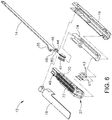
- FIGS. 1-7 depict an exemplary surgical stapling and severing instrument (10) that is sized for insertion, in a nonarticulated state as depicted in FIG. 1 , through a trocar cannula to a surgical site in a patient for performing a surgical procedure.
- a trocar may be inserted in a patient's abdomen, between two of the patient's ribs, or elsewhere.
- instrument (10) is used without a trocar.
- instrument (10) may be inserted directly through a thoracotomy or other type of incision.
- Instrument (10) of the present example includes a handle portion (20) connected to a shaft (22).
- Shaft (22) distally terminates in an articulation joint (11), which is further coupled with an end effector (12).
- end effector (12) is distal with respect to the more proximal handle portion (20).
- spatial terms such as “vertical” and “horizontal” are used herein with respect to the drawings. However, surgical instruments are used in many orientations and positions, and these terms are not intended to be limiting and absolute.
- shaft (22) is constructed in accordance with at least some of the teachings of U.S. Pub. No. 2014/0239038 , entitled “Surgical Instrument with Multi-Diameter Shaft,” published August 28, 2014, the disclosure of which is incorporated by reference herein.
- shaft (22) may be detachable from handle portion (20) in accordance with at least some of the teachings of U.S. Pub. No. 2015/0272575 , entitled “Surgical Instrument Comprising a Sensor System,” published October 1,2015, the disclosure of which is incorporated by reference herein.
- shaft (22) is not detachable from handle portion (20).
- Other suitable configurations for shaft (22) will be apparent to those of ordinary skill in the art in view of the teachings herein.
- articulation joint (11) may be remotely articulated, as depicted in phantom in FIG. 1 , by an articulation control (13), such that end effector (12) may be deflected from the longitudinal axis (LA) of shaft (22) at a desired angle ( ⁇ ). End effector (12) may thereby reach behind an organ or approach tissue from a desired angle or for other reasons.
- articulation joint (11) enables deflection of end effector (12) along a single plane.
- articulation joint (11) enables deflection of end effector along more than one plane.
- Articulation joint (11) and articulation control (13) may be configured in accordance with the teachings of any of the numerous references that are cited herein.
- articulation joint (11) and/or articulation control (13) may have any other suitable configuration.
- articulation control (13) may instead be configured as a knob that rotates about an axis that is perpendicular to the longitudinal axis (LA) of shaft (22).
- articulation joint (11) and/or articulation control (13) are/is constructed and operable in accordance with at least some of the teachings of U.S. Pat. No. 9,186,142 , entitled “Surgical Instrument End Effector Articulation Drive with Pinion and Opposing Racks,” issued on November 17, 2015, the disclosure of which is incorporated by reference herein.
- Articulation joint (11) may also be constructed and operable in accordance with at least some of the teachings of U.S. Pub. No. 2014/0239038 , entitled “Surgical Instrument with Multi-Diameter Shaft,” published August 28, 2014, the disclosure of which is incorporated by reference herein.
- Other suitable forms that articulation joint (11) and articulation control (13) may take will be apparent to those of ordinary skill in the art in view of the teachings herein.
- End effector (12) of the present example includes a lower jaw (16) and a pivotable anvil (18).
- lower jaw (16) is constructed in accordance with at least some of the teachings of U.S. Pub. No. 2014/0239044 , entitled “Installation Features for Surgical Instrument End Effector Cartridge,” published on August 28, 2014, the disclosure of which is incorporated by reference herein.
- Anvil (18) may be constructed in accordance with at least some of the teachings of U.S. Pub. No. 2014/0239042 , entitled “Integrated Tissue Positioning and Jaw Alignment Features for Surgical Stapler,” published on August 28, 2014, the disclosure of which is incorporated by reference herein; at least some of the teachings of U.S. Pub. No.
- Handle portion (20) includes a pistol grip (24) and a closure trigger (26).
- Closure trigger (26) is pivotable toward pistol grip (24) to cause clamping, or closing, of the anvil (18) toward lower jaw (16) of end effector (12).
- Such closing of anvil (18) is provided through a closure tube (32) and a closure ring (33), which both longitudinally translate relative to handle portion (20) in response to pivoting of closure trigger (26) relative to pistol grip (24).
- Closure tube (32) extends along the length of shaft (22); and closure ring (33) is positioned distal to articulation joint (11).
- Articulation joint (11) is operable to communicate/transmit longitudinal movement from closure tube (32) to closure ring (33).
- Handle portion (20) also includes a firing trigger (28).
- An elongate member (not shown) longitudinally extends through shaft (22) and communicates a longitudinal firing motion from handle portion (20) to a firing beam (14) in response to actuation of firing trigger (28).
- This distal translation of firing beam (14) causes the stapling and severing of clamped tissue in end effector (12), as will be described in greater detail below.
- triggers (26, 28) may be released to release the tissue from end effector (12).
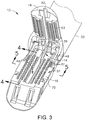
- FIGS. 3-6 depict end effector (12) employing an E-beam form of firing beam (14) to perform a number of functions.
- Firing beam (14) may take any other suitable form, including but not limited to non-E-beam forms.
- firing beam (14) includes a transversely oriented upper pin (38), a firing beam cap (44), a transversely oriented middle pin (46), and a distally presented cutting edge (48).
- Upper pin (38) is positioned and translatable within a longitudinal anvil slot (42) of anvil (18).
- Firing beam cap (44) slidably engages a lower surface of lower jaw (16) by having firing beam (14) extend through lower jaw slot (45) (shown in FIG. 4B ) that is formed through lower jaw (16).
- Middle pin (46) slidingly engages a top surface of lower jaw (16), cooperating with firing beam cap (44). Thereby, firing beam (14) affirmatively spaces end effector (12) during firing.
- firing beam (14) may lack upper pin (38), middle pin (46) and/or firing beam cap (44).
- instrument (10) may simply rely on closure ring (33) or some other feature to pivot anvil (18) to a closed position and hold anvil (18) in the closed position while firing beam (14) advances to the distal position.
- firing beam (14) and/or associated lockout features may be constructed and operable in accordance with at least some of the teachings of U.S. Pub. No. 2014/0239041 , entitled “Lockout Feature for Movable Cutting Member of Surgical Instrument," published on August 28, 2014, the disclosure of which is incorporated by reference herein.
- Other suitable forms that firing beam (14) may take will be apparent to those of ordinary skill in the art in view of the teachings herein.
- FIG. 3 shows firing beam (14) of the present example proximally positioned and anvil (18) pivoted to an open position, allowing an unspent staple cartridge (37) to be removably installed into a channel of lower jaw (16).
- staple cartridge (37) of this example includes a cartridge body (70), which presents an upper deck (72) and is coupled with a lower cartridge tray (74).
- a vertical slot (49) is formed through part of staple cartridge (37).
- three rows of staple apertures (51) are formed through upper deck (72) on one side of vertical slot (49), with another set of three rows of staple apertures (51) being formed through upper deck (72) on the other side of vertical slot (49).
- a wedge sled (41) and a plurality of staple drivers (43) are captured between cartridge body (70) and tray (74), with wedge sled (41) being located proximal to staple drivers (43).
- Wedge sled (41) is movable longitudinally within staple cartridge (37); while staple drivers (43) are movable vertically within staple cartridge (37).
- Staples (47) are also positioned within cartridge body (70), above corresponding staple drivers (43).
- each staple (47) is driven vertically within cartridge body (70) by a staple driver (43) to drive staple (47) out through an associated staple aperture (51).
- wedge sled (41) presents inclined cam surfaces that urge staple drivers (43) upwardly as wedge sled (41) is driven distally through staple cartridge (37).
- staple cartridge (37) is constructed and operable in accordance with at least some of the teachings of U.S. Pub. No. 2014/0239042 , entitled “Integrated Tissue Positioning and Jaw Alignment Features for Surgical Stapler,” published on August 28, 2014, the disclosure of which is incorporated by reference herein.
- staple cartridge (37) may be constructed and operable in accordance with at least some of the teachings of U.S. Pub. No. 2014/0239044 , entitled “Installation Features for Surgical Instrument End Effector Cartridge,” published on August 28, 2014, the disclosure of which is incorporated by reference herein.
- Other suitable forms that staple cartridge (37) may take will be apparent to those of ordinary skill in the art in view of the teachings herein.
- firing beam (14) is then advanced in engagement with anvil (18) by having upper pin (38) enter longitudinal anvil slot (42).
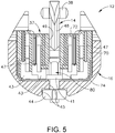
- a pusher block (80) (shown in FIG. 5 ) is located at the distal end of firing beam (14), and is configured to engage wedge sled (41) such that wedge sled (41) is pushed distally by pusher block (80) as firing beam (14) is advanced distally through staple cartridge (37) when firing trigger (28) is actuated.
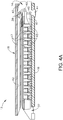
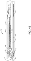
- FIGS. 4A-4B depicts firing beam (14) fully distally translated after completing severing and stapling of tissue.
- staple forming pockets (53) are intentionally omitted from the view in FIGS. 4A-4B ; but staple forming pockets (53) are shown in FIG. 3 . It should also be understood that anvil (18) is intentionally omitted from the view in FIG. 5 .
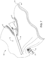
- FIG. 7 shows end effector (12) having been actuated through a single stroke through tissue (90).
- cutting edge (48) (obscured in FIG. 7 ) has cut through tissue (90), while staple drivers (43) have driven three alternating rows of staples (47) through the tissue (90) on each side of the cut line produced by cutting edge (48).
- Staples (47) are all oriented substantially parallel to the cut line in this example, though it should be understood that staples (47) may be positioned at any suitable orientations.
- end effector (12) is withdrawn from the trocar after the first stroke is complete, spent staple cartridge (37) is replaced with a new staple cartridge, and end effector (12) is then again inserted through the trocar to reach the stapling site for further cutting and stapling. This process may be repeated until the desired amount of cuts and staples (47) have been provided.
- Anvil (18) may need to be closed to facilitate insertion and withdrawal through the trocar; and anvil (18) may need to be opened to facilitate replacement of staple cartridge (37).
- cutting edge (48) may sever tissue substantially contemporaneously with staples (47) being driven through tissue during each actuation stroke.
- cutting edge (48) just slightly lags behind driving of staples (47), such that a staple (47) is driven through the tissue just before cutting edge (48) passes through the same region of tissue, though it should be understood that this order may be reversed or that cutting edge (48) may be directly synchronized with adjacent staples.
- FIG. 7 shows end effector (12) being actuated in two layers (92, 94) of tissue (90), it should be understood that end effector (12) may be actuated through a single layer of tissue (90) or more than two layers (92, 94) of tissue.
- FIG. 7 shows end effector (12) being actuated in two substantially flat, apposed planar layers (92, 94) of tissue, it should be understood that end effector (12) may also be actuated across a tubular structure such as a blood vessel, a section of the gastrointestinal tract, etc.
- FIG. 7 should therefore not be viewed as demonstrating any limitation on the contemplated uses for end effector (12).
- instrument (10) may be used will be apparent to those of ordinary skill in the art in view of the teachings herein.
- instrument (10) provides motorized control of firing beam (14).
- Exemplary components that may be used to provide motorized control of firing beam (14) are shown and described in US. Pub. No. 2014/0239043 , entitled “Distal Tip Features for End Effector of Surgical Instrument,” published on August 28, 2014, the disclosure of which is incorporated by reference herein.
- at least part of the motorized control may be configured in accordance with at least some of the teachings of U.S. Pat. No. 8,210,411 , entitled “Motor-Driven Surgical Instrument,” issued July 3, 2012, the disclosure of which is incorporated by reference herein.
- the features operable to drive firing beam (14) may be configured in accordance with at least some of the teachings of U.S. Pub. No. 2012/0239012 , the disclosure of which is incorporated by reference herein; and/or in accordance with at least some of the teachings of U.S. Pub. No. 2012/0239012 , the disclosure of which is also incorporated by reference herein.
- Other suitable components, features, and configurations for providing motorization of firing beam (14) will be apparent to those of ordinary skill in the art in view of the teachings herein. It should also be understood that some other versions may provide manual driving of firing beam (14), such that a motor may be omitted.
- firing beam (14) may be actuated in accordance with at least some of the teachings of any other patent/publication reference cited herein.
- Instrument (10) may also include a lockout switch and lockout indicator as shown and described in US. Pub. No. 2014/0239043 , entitled “Distal Tip Features for End Effector of Surgical Instrument,” published on August 28, 2014, the disclosure of which is incorporated by reference herein. Additionally, a lockout switch and/or lockout indication and associated components/functionality may be configured in accordance with at least some of the teachings of U.S. Patent No. 7,644,848 , entitled “Electronic Lockouts and Surgical Instrument Including Same,” issued January 12, 2010, the disclosure of which is incorporated by reference herein.
- Instrument (10) also include a manual return switch (116) configured to act as a "bailout” feature, enabling the operator to quickly begin retracting firing beam (14) proximally during a firing stroke.
- manual return switch (116) may be manually actuated when firing beam (14) has only been partially advanced distally.
- Manual return switch (116) may provide further functionality in accordance with at least some of the teachings of U.S. Pub. No. 2014/0239043 , entitled “Distal Tip Features for End Effector of Surgical Instrument,” published on August 28, 2014, the disclosure of which is incorporated by reference herein.
- anvil (18) pivots about an axis that is defined by a pin (or similar feature) that slides along an elongate slot or channel as anvil (18) moves toward lower jaw (16).
- the pivot axis translates along the path defined by the slot or channel while anvil (18) simultaneously pivots about that axis.
- the pivot axis may slide along the slot/channel first, with anvil (18) then pivoting about the pivot axis after the pivot axis has slid a certain distance along the slot/channel.
- pivotal movement is encompassed within terms such as “pivot,” “pivots,” “pivotal,” “pivotable,” “pivoting,” and the like.
- some versions may provide pivotal movement of anvil (18) about an axis that remains fixed and does not translate within a slot or channel, etc.
- instrument (10) may be configured and operable in accordance with any of the teachings of U.S. Pat. No. 4,805,823 ; U.S. Pat. No. 5,415,334 ; U.S. Pat. No. 5,465,895 ; U.S. Pat. No. 5,597,107 ; U.S. Pat. No. 5,632,432 ; U.S. Pat. No. 5,673,840 ; U.S. Pat. No. 5,704,534 ; U.S. Pat. No. 5,814,055 ; U.S. Pat. No. 6,978,921 ; U.S. Pat. No. 7,000,818 ; U.S. Pat. No. 7,143,923 ; U.S.
- end effector (12) it may be desirable to provide the user with better visualization of end effector (12).
- end effector (12) as end effector (12) is inserted into a surgical site, the user may rotate shaft (22) of instrument (10) during the procedure. As a result, end effector (12) also rotates. As end effector (12) rotates, it may be desirable for the user to have visual access to the surgical site. For instance, the user may wish to see the interface or contact between tissue (90) and end effector (12). Since end effector (12) may be rotated about the longitudinal axis (LA) relative to handle portion (20), the user may view the surgical site such that lower jaw (16) of end effector is visible rather than anvil (18).
- LA longitudinal axis
- end effector (12) could be rotated such that when the user views end effector (12), anvil (18) is visible by the user. It may be desirable to provide visibility of the surgical site for the user beyond what is possible in instrument (10) of FIG. 1 . For instance, in the case of some surgical procedures where fluid carrying vessels are transected and stapled, it may be desirable to have visual confirmation that anvil (18) and lower jaw (16) completely cover the vessel to be cut, such that the vessel may be fully cut and stapled in one single actuation. In other words, the user may wish to avoid cutting and stapling only a portion of a vessel.
- end effector (12) may be desirable so that the user will know that end effector (12) has been positioned properly within the surgical site for anvil (18) and lower jaw (16) to fully clamp the vessel.
- One potential way of monitoring the surgical site may include improving visualization of the area adjacent to the distal tip of lower jaw (16) and anvil (18).
- end effector (12) may be desirable, but also it may be desirable to construct end effector (12) such that the distal end of anvil (18) is configured to urge tissue (e.g., a large vessel) proximally into the space between anvil (18) and lower jaw (16) as anvil (18) closes toward lower jaw (16).
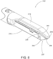
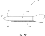
- FIG. 8 depicts an exemplary end effector (212) comprising an anvil (218) and a lower jaw (216). It will be appreciated that end effector (212) may be used in place of end effector (12) of instrument (10). End effector (212) may be integrally formed with instrument (10) or in the alternative may be interchangeable with end effector (12) of instrument (10).
- Anvil (218) is operable to pivot relative to lower jaw (216).
- Anvil (218) and lower jaw (216) may clamp tissue (90) similarly to clamping performed by anvil (18) and lower jaw (16) shown in FIG. 1 .
- End effector (212) further comprises a cartridge (237) operable to be placed in lower jaw (216) similarly to cartridge (37) shown in FIG. 3 .
- Anvil (218) as can be seen in FIGS. 8-10 has an elongated shape where the distal portion of anvil (218) angles toward cartridge (237).
- the distal portion of anvil (218) angles toward cartridge (237) such that the distal most tip (219) of anvil (218) extends distally longitudinally further than cartridge (237).
- distal tip (219) may extend to a distance longitudinally equal to cartridge (237) or proximal relative to the distal most point on cartridge (237).
- anvil (218) angles toward cartridge (237) through a gentle slope.
- anvil (218) includes sides (241) that taper as they approach the distal most tip (219) of anvil (218).
- anvil (218) is shaped in FIG. 8 similarly to an inverted ski tip.
- the angled shape of anvil (218) may provide easier insertion of end effector (212) into a surgical site.
- the gentle slope or inverted ski tip shape of anvil (218) may provide an atraumatic tissue deflection surface as anvil (218) contacts or moves through tissue.
- Such atraumatic tissue deflection may include urging tissue (e.g., a large vessel) proximally into the space between anvil (218) and lower jaw (216) as anvil (218) closes toward lower jaw (216).
- anvil (218) may also provide better maneuverability of end effector (212) and better visibility of the distal end of end effector (212) in relation to anatomical structures at the surgical site.
- Other suitable variations of anvil (218) will be apparent to one of ordinary skill in the art in view of the teachings herein.
- Cartridge (237) is operable to hold staples similar to staples (47) shown in FIG. 4A for driving into tissue.
- the distal end of cartridge (237) has a triangular profile.
- the distal end of cartridge (237) comprises an upper tapered surface (239) and a lower tapered surface (238).
- the distal end of cartridge (237) comprises a tapered side surface (243) on each side.
- each tapered side surface (243) of cartridge (237) generally aligns with the taper presented by sides (241) of anvil (218).
- side surfaces (243) of cartridge (237) do not extend outwardly from longitudinal axis (LA) of end effector (212) past sides (241) of anvil (218).
- Upper tapered surface (239) and lower tapered surface (238) lead to the distal most end of cartridge (237).
- Lower tapered surface (238) defines a sight line (240) such that once end effector (212) is inserted into a surgical site, the user can see along sight line (240).
- Sight line (240) extends along the edge of lower tapered surface (238). It will be appreciated that the planar shape of lower tapered surface (238) may be operable to allow the user to visualize and/or nearly visualize the distal tip (219) of anvil (218).
- sight line (240) intersects longitudinal axis (LA), which extends longitudinally through end effector (212), to form a viewing angle ( ⁇ ).
- Viewing angle ( ⁇ ) may establish the relative visibility that a user has regarding distal tip (219).
- the user can see in front of distal tip (219) along any line of sight that passes through the intersection of sight line (240) and longitudinal axis (LA) within viewing angle ( ⁇ ).
- viewing angle ( ⁇ ) defines an angle greater than 90 degrees.
- viewing angle ( ⁇ ) defines an angle greater than 135 degrees.
- the user generally looks along sight line (240) or along some other line of sight within viewing angle ( ⁇ ), thus, the user has visibility along sight line as well as any area within viewing angle ( ⁇ ).
- the underside of distal tip (219) is further slightly rounded to aid in the visibility of the intersection of longitudinal axis (LA) and sight line (240).
- tissue (90) When tissue (90) is clamped between a closed cartridge (237) and anvil (218), the user can look along sight line (240) or elsewhere within viewing angle ( ⁇ ) to see, for instance, precisely where anvil (218) has clamped tissue (90). Furthermore, the user would be able to determine whether the tissue is completely clamped between anvil (218) and cartridge (237) such that tissue does not spill over the end of end effector (212). The user may be able to also visualize the quality of the clamp between anvil (218) and cartridge (237) against tissue (90).
- end effector (212) may be rotated before, during, or after clamping tissue (90).
- the tapered shape of anvil (218) may also provide more accessible viewing of distal tip (219) or substantially adjacent distal tip (219).
- the taper of anvil (218) along with lower tapered surface (238) of cartridge (237) may further promote easy insertion of end effector (212) into tissue in an atraumatic manner.
- lower tapered surface (238) and the tapered shape of anvil (218) may provide a lead-in, guiding the rest of end effector (212) into the trocar.
- end effector (212) and versions of instrument (10) incorporating end effector (212) may be configured and operable in accordance with at least some of the teachings of U.S. Pat. No. 9,186,142 , entitled “Surgical Instrument End Effector Articulation Drive with Pinion and Opposing Racks,” issued November 17, 2015, the disclosure of which is incorporated by reference herein; U.S. Pub. No. 2014/0239041 , entitled “Lockout Feature for Movable Cutting Member of Surgical Instrument,” published August 28, 2014, the disclosure of which is incorporated by reference herein; U.S. Pat. No.
- instrument (10) may be placed at the surgical site, actuated to cut and staple, then removed from the surgical site for installing a new cartridge (37), and then be placed back at the surgical site again for the next cut and staple along the same path in which the previous cutting and stapling cycle occurred. This process is repeated until the cut and staple procedure is complete. As can be seen in FIGS. 4A-4B and FIG.
- the distal end configuration of end effector (12) provides a gap between the distal end of anvil (18) and the distal end of cartridge (37). This gap may facilitate marching by providing an atraumatic space for tissue to enter the distal end of end effector (12) at the beginning of each marching step.
- the distal end configuration of end effector (212) is different from the distal end configuration of end effector (12); with the different configuration of end effector (212) providing different potential advantages.
- the distal end configuration of end effector (212) may provide improved maneuverability and improved visibility of the relationship between the distal end of end effector (212) and adjacent anatomical structures.
- the distal end configuration of end effector (212) may provide tissue-gathering effects by urging tissue proximally into the space between anvil (218) and lower jaw (216) as anvil (218) is closed toward lower jaw (216).
- end effector (212) may not lend itself well to marching operations, as distal tip (219) may impart trauma to tissue that is not gathered into the space between anvil (218) and lower jaw (216) as anvil (218) is closed toward lower jaw (216).
- end effector (212) may be best suited for cutting and stapling operations (e.g., vessel transection) where all of the tissue that is to be cut and stapled is gathered proximal to distal tip (219).
- end effectors (12, 212) that provides the marching capabilities of end effector (12), the improved visibility associated with end effector (212), and the tissue gathering capabilities of end effector (212), without providing an increased risk of trauma that might otherwise be associated with fully rigid versions of end effector (212).
- an anvil has a distal tip that is resiliently biased to assume a bent or angled configuration like distal tip (219); yet the resiliently biased distal tip is deflectable away from the lower jaw in response to a sufficient load on the distal tip.
- an anvil with an elastically deformable angled distal tip portion can provide an additional level of maneuverability benefits in terms of navigating through tissue to a surgical site.
- the deformable distal tip portion may deflect or deform to promote smooth and atraumatic movement of the end effector through tissue, particularly during marching operations.
- an anvil having a bias to an angled position when not in a loaded state or contacted by surrounding tissue enhanced visualization during tissue capture and cutting can be achieved compared to using end effectors with a straight or non-angled anvil.
- an anvil with a distal tip that is biased to an angled position may provide some degree of tissue gathering effects up until reaching a load point that would be associated with marching rather than being associated with simply gathering a relatively small tissue structure between the anvil and lower jaw.
- end effectors that incorporate modular releasable anvil tips where the tips may be elastically deformable
- enhanced tissue gripping can be achieved using end effectors having anvil tips and cartridge noses with cooperating features.
- cooperating features may provide a lock or tissue stop that prevents clamped tissue from moving out of the distal end of the end effector during a cutting and stapling action.
- cooperating features may also act as a tactile feedback feature to signal to a user that they have completely clamped the tissue, vessel, or tubular structure by feeling the cooperating features engage or contact at the distal end.
- such cooperating features can similarly act as a feedback feature or structure to signal to a user that they are at the end of the tissue path, as evidenced by the cooperating features engaging or contacting at the distal end (as opposed to the respective cooperating features each contacting tissue). Additionally, as described further below, to ensure that the matching anvil tips and cartridges tips are used together, such anvil tips and cartridges with cooperating features can be provided as a kit with a loading and/or unloading cartridge or tool.
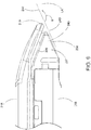
- FIG. 11 depicts an exemplary end effector (312) comprising an anvil (318) and a lower jaw (316). It will be appreciated that end effector (312) may be used in place of end effector (12) of instrument (10). End effector (312) may be integrally formed with instrument (10) or in the alternative may be interchangeable with end effector (12) of instrument (10). Anvil (318) is operable to pivot relative to lower jaw (316). Anvil (318) and lower jaw (316) may clamp tissue (90) similarly to clamping performed by anvil (18) and lower jaw (16) shown in FIG. 1 . End effector (312) further comprises a cartridge (337) that is operable to be placed in lower jaw (316) similarly to cartridge (37) shown in FIG. 3 .
- Anvil (318) comprises an anvil body (320) and an anvil tip (319).
- Anvil (318) has an elongated shape where anvil body (320) is straight and anvil tip (319) extends distally in an angled or curved manner toward cartridge (337).
- Anvil tip (319) includes sides (322) that taper as they approach the distal-most part of anvil tip (319), although such a tapered configuration is not required in all versions.
- anvil (318) is shaped in FIGS. 11 and 12 with the shape of anvil tip (319) being similar to an inverted ski tip. This may provide easier insertion of end effector (312) into a surgical site.
- anvil tip (319) may provide an atraumatic tissue deflection surface as anvil (318) contacts or moves through tissue.
- the angled shape of anvil tip (319) may provide better maneuverability of end effector (312).
- Other suitable variations of anvil (318) will be apparent to one of ordinary skill in the art in view of the teachings herein.
- angled and curved shall be read as being synonymous with each other when referring to a distal end configuration of a component of an end effector.
- the term “curved” (and variations thereof) may include a relationship between two straight features that together define an angle, such that the term “curved” (and variations thereof) should not be read as requiring a component to necessarily extend along an arc.
- Anvil (318) further comprises staple forming pockets (53) as described above; and longitudinal anvil slot (42) as also described above.
- anvil tip (319) is configured as a modular releasable component that selectively connects with or attaches to anvil body (320).
- anvil tip (319) comprises an insert or other structure that extends proximally and is configured to be received within a distal end of longitudinal slot (42).
- Anvil tip (319) comprises a bottom surface (324) that faces cartridge (337) and that is configured to contact tissue (90) when end effector (312) is in a loaded state clamping tissue (90).
- anvil tip (319) comprises one or more features (326) that are configured to also contact tissue (90) when end effector (312) is in a loaded state.
- one or more features (326) comprise a pair of raised arcuate ribs that generally extend transversely across a width of anvil tip (319). In this manner, the raised arcuate ribs protrude or extend from bottom surface (324) toward cartridge (337). While the present example shows two such ribs, in other versions anvil tip (319) comprises greater or fewer ribs.
- one or more features (326) are positioned along or closer to a distal end of anvil tip (319) rather than along a proximal end of anvil tip (319). In some other versions, however, one or more features (326) can be located along a middle portion, proximal end, or other portions of bottom surface (324) of anvil tip (319).
- Anvil tip (319) is comprised of an elastomeric material in the present example. With such a construction, in use during clamping tissue, anvil tip (319) may deflect or bend from a curved state to a straight or less curved state. By way of example only, tip (319) may be deflectable between about 20 degrees and about 70 degrees in a downward direction from a longitudinal axis toward cartridge; between about 0 degrees and about 90 degrees in an upward direction from a longitudinal axis toward cartridge (337). The degree of deflection may be influenced by the thickness and/or density of the tissue that is being compressed between anvil (318) and cartridge (337).
- anvil tip (319) may deflect or bend from a curved state to a straight or less curved state in accordance with at least some of the teachings in U.S. Pat. App. No. [ATTORNEY DOCKET NO. END8115USNP.0641880], entitled “Surgical Stapler with Elastically Deformable Tip,” filed on even date herewith, the disclosure of which is incorporated by reference herein.
- anvil tip (319) is operably configured for use in procedures where marching is used.
- one or more features (326) are similarly formed of an elastomeric material such that they are also elastically deformable.
- one or more features (326) are elastically deformable to a different extent than anvil tip (319) generally.
- one or more features (326) can be elastically deformable to the same or to a greater extent compared to anvil tip (319) generally.
- various ways to modify and manipulate the degree or extent of elastic deformability of one or more features (326) and/or anvil tip (319) generally will be apparent to those of ordinary skill in the art.
- anvil tip (319) and/or its one or more features (326) are not required to be elastically deformable and thus may be rigid.
- Cartridge (337) is operable to hold staples similar to staples (47) shown in FIG. 4A for driving into tissue.
- cartridge (337) comprises a nose portion (344) at a distal end.
- Cartridge nose (344) has a triangular profile.
- cartridge nose (344) comprises an upper tapered surface (339), a bottom surface (340), and side surfaces (342).
- bottom surface (340) is generally parallel with a longitudinal axis defined by cartridge (337).
- bottom surface (340) is angled toward the longitudinal axis defined by cartridge (337), similar to the configuration shown above with respect to cartridge (237).
- cartridge (337) comprises one or more features (346) that are configured to also contact tissue (90) when end effector (312) is in a loaded state.
- one or more features (346) comprise a pair of raised arcuate ribs that generally extend transversely across a width of cartridge (337). In this manner, the raised arcuate ribs protrude or extend from upper surface (339) toward anvil tip (319). While the present example shows three such ribs, in other versions nose portion (344) of cartridge (337) comprises greater or fewer ribs.
- one or more features (346) are positioned along or closer to a middle and distal end of nose portion (344) rather than along a proximal end of nose portion (344). In some other versions, however, one or more features (346) can be located along a proximal end, or other portions of upper surface (339) of cartridge (337).
- cartridge (337) and one or more features (346) protruding from nose portion (344) are rigid such that they do not elastically deform when end effector (312) is in a loaded state clamping tissue (90). Furthermore, when end effector (312) is closed and in a non-loaded state not clamping tissue, one or more features (346) of cartridge (337) are configured to complement one or more features (326) of anvil tip (319). In this manner, when tissue (90) is not present within end effector (312), one or more features (346) of cartridge (337) and one or more features (326) of anvil tip (319) cooperate to form a nesting arrangement.
- one or more features (326) of anvil tip (319) are positionable adjacent to one or more features (346) of cartridge (337).
- a distal-most rib of anvil tip (319) is positioned adjacent to and proximal to a distal-most rib of cartridge (337).
- a distal-most rib of anvil tip (319) is positioned adjacent to and distal to a distal-most rib of cartridge (337).
- end effector (312) comprises the combination of elastically deformable anvil tip (319) having one or more features (326), combined with rigid cartridge nose (344) having one or more features (346). Furthermore, as described above the one or more features (326) cooperate with, or are complementary to, the one or more features (346).
- one or more features (346) of cartridge nose (344) can be configured as elastically deformable while one or more features (326) of anvil tip (319) can be configured as rigid. Still yet in other versions, both of one or more features (326, 346) can be elastically deformable, or both can be rigid.
- bottom surface (324) of anvil tip (319) and upper surface (339) of cartridge nose portion (344) are generally parallel surfaces.
- This parallel orientation promotes equal nesting of one or more features (326) of anvil (319) with one or more features (346) of nose portion (344).
- the most distal features (326, 346) will nest to the same extent or degree as the most proximal features (326, 346).
- this parallel orientation provides for a consistent gap between those portions of anvil bottom surface (324) and cartridge upper surface (339) not having the one or more features (326, 346).
- other arrangements for the orientation of bottom surface (324) and upper surface (339), including non-parallel arrangements will be apparent to those of ordinary skill in the art.
- FIG. 11 is described as one or more features (326) of anvil tip (319) and one or more features (346) of cartridge nose (344) adopting a nesting arrangement
- such an arrangement may be a contacting arrangement where one or more features (326) of anvil tip (319) contact with upper surface (339) of cartridge nose (344) when end effector (312) is closed and in an unloaded state and/or one or more features (346) of cartridge nose (344) contact with bottom surface (324) of anvil tip (319) when end effector (312) is closed and in an unloaded state.
- the gap between the flat regions of bottom surface (324) and upper surface (339) generally equals the distance that the protruding ribs extend away from their respective bottom surface (324) and upper surface (339).
- one or more features (326, 346) contact tissue in a manner that applies staggered concentrations of force to clamped tissue (90). These staggered concentrations of force coincide with the locations where one or more features (326, 346) that protrude from respective anvil tip (319) and cartridge nose (344) contact tissue (90).
- the one or more features (326, 346) also provide a tissue stop or locking feature that prevents tissue (90) that is clamped between anvil (318) and cartridge (337) from spilling over the end of end effector (312).
- end effector (312) may be rotated before, during, or after clamping tissue (90).
- the curved shape of anvil (318) may also provide more accessible viewing of anvil tip (319) or regions substantially adjacent anvil tip (319).
- the curve of anvil (318) may further promote easy insertion of end effector (312) into tissue in an atraumatic manner.
- it may be easier to fit end effector (312) through a trocar or other devices operable to introduce end effector (312) into a surgical site due to the curve of anvil (318) of end effector (312).
- cartridge (337) comprises vertical slot (349) having the same or similar structure and function as vertical slot (49) discussed above.
- Cartridge (337) also comprises staple apertures (351) having the same or similar structure and function as staple apertures (51) discussed above.
- cartridge (337) is generally flat along a staple deck (348) with staple apertures (351) being along the same plane defined by staple deck (348).
- cartridge (337) comprises shelf (350), which is also flat but is slightly recessed relative to staple deck (348).
- cartridge (337) may be modified similar to cartridge (37) above by having cartridge (337) include separate raised areas and recessed areas such that one row of staple apertures (51) may be higher or lower than another row of staple apertures (51).
- staple deck (348) of cartridge (337) could be modified so that staple deck (348) defines more than one plane and staple apertures (351) are not all along the same plane, but instead are found of different planes that face anvil (318).
- FIG. 11 illustrates anvil body (320) as having recessed areas (328) along an outer region of anvil body (320).
- anvil body (320) has a raised area (330) along a center region of anvil body (320).
- anvil (317) may comprise anvil body (321) having a flat area (332) along the portion of anvil body (321) having staple forming pockets (53).
- staple forming pockets (53) may be co-planar, yet in other instances staple forming pockets (53) may be located along different planes defined by the undersurface of anvil body (320).
- anvils (317, 318) are identical except for the underside surface configuration as described here. In view of the teachings herein, various modifications and other ways to configure anvils (317, 318) will be apparent to those of ordinary skill in the art.
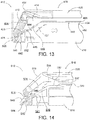
- FIG. 13 illustrates another exemplary end effector (412) comprising anvil (418) and lower jaw (416).
- end effector (412) may be used in place of end effector (12) of instrument (10).
- End effector (412) may be integrally formed with instrument (10) or in the alternative may be interchangeable with end effector (12) of instrument (10).
- Anvil (418) is operable to pivot relative to lower jaw (416).
- Anvil (418) and lower jaw (416) may clamp tissue (90) similarly to clamping performed by anvil (18) and lower jaw (16) shown in FIG. 1 .
- End effector (412) further comprises a cartridge (437) that is operable to be placed in lower jaw (416) similarly to cartridge (37) shown in FIG. 3 .
- Anvil (418) is similar to anvil (318) described above.
- Anvil (418) comprises an anvil body (420) and an anvil tip (419).
- Anvil (418) has an elongated shape where anvil body (420) is straight and anvil tip (419) extends distally in an angled or curved manner toward cartridge (437).
- anvil tip (419) is shaped similar to an inverted ski tip. This may provide easier insertion of end effector (412) into a surgical site.
- the gentle slope or inverted ski tip shape of anvil tip (419) may provide an atraumatic tissue deflection surface as anvil (418) contacts or moves through tissue.
- the angled shape of anvil tip (419) may provide better maneuverability of end effector (412).
- Other suitable variations of anvil (418) will be apparent to one of ordinary skill in the art in view of the teachings herein.
- Anvil (418) further comprises staple forming pockets (not shown) as described above, and a longitudinal anvil slot (42) as also described above.
- anvil tip (419) is configured as a modular releasable component that selectively connects with or attaches to anvil body (420).
- anvil tip (419) comprises a fastener (434) such as an insert, shim, or other structure that extends proximally and is configured to be received within a distal end of longitudinal slot (42).
- Anvil tip (419) comprises a bottom surface (424) that faces cartridge (437) and that is configured to contact tissue (90) when end effector (412) is in a loaded state clamping tissue (90).
- anvil tip (419) comprises one or more features (426) that are configured to also contact tissue (90) when end effector (412) is in a loaded state.
- one or more features (426) comprise a pair of raised ribs that generally extend transversely across a width of anvil tip (419). In this manner, the raised ribs protrude or extend from bottom surface (424) toward cartridge (437). While the present example shows two such ribs, in other versions anvil tip (419) comprises greater or fewer ribs.
- one or more features (426) are positioned along or closer to a distal end of anvil tip (419) rather than along a proximal end of anvil tip (419).
- the pair of raised ribs are configured such that anvil tip (419) distally terminates at one of the pair of raised ribs.
- one of the one or more features (426) is located at the distal end of anvil tip (419), with the other one of the one or more features (426) being proximal thereof as shown in FIG. 13 .
- one or more features (426) can be located along a middle portion, proximal end, or other portions of bottom surface (424) of anvil tip (419).
- anvil tip (419) comprises a steeper angle or greater amount of curvature compared to anvil tip (319).
- a longitudinal axis defined by anvil body (420), and a longitudinal axis defined by a distal portion of anvil tip (419) intersect to form an angle of between about 110 degrees and about 125 degrees.
- the same angle with anvil tip (319) and body (320) is greater as the angle of anvil tip (319) relative to anvil body (320) is more gradual.
- the same angle for anvil tip (319) and anvil body (320) in one version is between about 135 degrees and about 160 degrees. Still with either anvil tip (319, 419), these angles may be larger or smaller as those of ordinary skill in the art will understand in view of the teachings herein.
- Anvil tip (419) is comprised of an elastomeric material in the present example. With such a construction, in use during clamping tissue anvil tip (419) may deflect or bend from a curved state to a straight or less curved state.
- tip (419) may be deflectable between about 20 degrees and about 70 degrees in a downward direction from a longitudinal axis toward cartridge; between about 0 degrees and about 90 degrees in an upward direction from a longitudinal axis toward cartridge (437).
- the degree of deflection may be influenced by the thickness and/or density of the tissue that is being compressed between anvil (418) and cartridge (437).
- anvil tip (319) may deflect or bend from a curved state to a straight or less curved state in accordance with at least some of the teachings in U.S. Pat. App. No. [ATTORNEY DOCKET NO. END8115USNP.0641880], entitled “Surgical Stapler with Elastically Deformable Tip,” filed on even date herewith, the disclosure of which is incorporated by reference herein.
- anvil tip (419) is operably configured for use in procedures where marching is used.
- one or more features (426) are similarly formed of an elastomeric material such that they are also elastically deformable.
- one or more features (426) are elastically deformable to a different extent than anvil tip (419) generally.
- one or more features (426) can be elastically deformable to the same or to a greater extent compared to anvil tip (419) generally.
- various ways to modify and manipulate the degree or extent of elastic deformability of one or more features (426) and/or anvil tip (419) generally will be apparent to those of ordinary skill in the art.
- anvil tip (419) and/or its one or more features (426) are not required to be elastically deformable and thus may be rigid.
- Cartridge (437) is operable to hold staples similar to staples (47) shown in FIG. 4A for driving into tissue.
- cartridge (437) comprises a nose portion (444) at a distal end.
- Cartridge nose (444) has a triangular profile.
- cartridge nose (444) comprises an upper tapered surface (439), a bottom surface (440), and side surfaces (442).
- bottom surface (440) is generally parallel with a longitudinal axis defined by cartridge (437).
- bottom surface (440) is angled toward the longitudinal axis defined by cartridge (437), similar to the configuration shown above with respect to cartridge (237).
- cartridge (437) comprises one or more features (446) that are configured to also contact tissue (90) when end effector (412) is in a loaded state.
- one or more features (446) comprise a pair of raised ribs that generally extend transversely across a width of cartridge (437). In this manner, the raised ribs protrude or extend from upper surface (439) toward anvil tip (419). While the present example shows two such ribs, in other versions nose portion (444) of cartridge (437) comprises greater or fewer ribs. Also, in the present example, one or more features (446) are positioned along or closer to a middle and distal end of nose portion (444) rather than along a proximal end of nose portion (444). In some other versions, however, one or more features (446) can be located along a proximal end, or other portions of, upper surface (439) of cartridge (437).
- cartridge (437) and one or more features (446) protruding from nose portion (444) are rigid such that they do not elastically deform when end effector (412) is in a loaded state clamping tissue (90). Furthermore, when end effector (412) is closed and in a non-loaded state not clamping tissue, one or more features (446) of cartridge (437) are configured to complement one or more features (426) of anvil tip (419). In this manner, when tissue (90) is not present within end effector (412), one or more features (446) of cartridge (437) and one or more features (426) of anvil tip (419) cooperate to form a nesting arrangement.
- one or more features (426) of anvil tip (419) are positionable adjacent to one or more features (446) of cartridge (437).
- a distal-most rib of anvil tip (419) is positioned adjacent to and distal to a distal-most rib of cartridge (437).
- a distal-most rib of anvil tip (419) can be positioned adjacent to and proximal to a distal-most rib of cartridge (437), similar to end effector (312) described above.
- end effector (412) comprises the combination of elastically deformable anvil tip (419) having one or more features (426), combined with rigid cartridge nose (444) having one or more features (446). Furthermore, as described above the one or more features (426) cooperate with, or are complementary to, the one or more features (446).
- one or more features (446) of cartridge nose (444) can be configured as elastically deformable while one or more features (426) of anvil tip (419) can be configured as rigid. Still yet in other versions, both of one or more features (426, 446) can be elastically deformable, or both can be rigid.
- bottom surface (424) of anvil tip (419) and upper surface (439) of cartridge nose portion (444) are generally parallel surfaces. This parallel orientation promotes equal nesting of one or more features (426) of anvil (419) with one or more features (446) of nose portion (444). For instance, in the present example, the most distal features (426, 446) will nest to the same extent or degree as the most proximal features (326, 446).
- other arrangements for the orientation of bottom surface (424) and upper surface (439), including non-parallel arrangements will be apparent to those of ordinary skill in the art.
- Anvil tip (419) has a steep angle as described above.
- anvil tip (419) comprises a rear surface (436) that extends along the distal portion of anvil tip (419) that defines the longitudinal axis of anvil tip (419) as described above.
- rear surface (436) is not parallel with upper surface (439) of cartridge (437).
- end effector (412) comprises a void space (414) between anvil tip (419) and upper surface (439) of cartridge (437).
- void space (414) has a triangular profile.
- FIG. 13 is described as one or more features (426) of anvil tip (419) and one or more features (446) of cartridge nose (444) adopting a nesting arrangement
- such an arrangement may be a contacting arrangement where one or more features (426) of anvil tip (419) contact with upper surface (439) of cartridge nose (444) when end effector (412) is closed and in an unloaded state and/or one or more features (446) of cartridge nose (444) contact with bottom surface (424) of anvil tip (419) when end effector (412) is closed and in an unloaded state.
- the gap between the flat regions of bottom surface (424) and upper surface (439) generally equals the distance the protruding ribs extend away from their respective bottom surface (424) and upper surface (439).
- one or more features (426, 446) contact tissue in a manner that applies staggered concentrations of force to clamped tissue (90). These staggered concentrations of force coincide with the locations where one or more features (426, 446) that protrude from respective anvil tip (419) and cartridge nose (444) contact tissue (90).
- the one or more features (426,446) also provide a tissue stop or locking feature that prevents tissue (90) that is clamped between anvil (418) and cartridge (437) from spilling over the end of end effector (412).
- end effector (412) may be rotated before, during, or after clamping tissue (90).
- the curved shape of anvil (418) may also provide more accessible viewing of anvil tip (419) or regions substantially adjacent anvil tip (419).
- the curve of anvil (418) may further promote easy insertion of end effector (412) into tissue in an atraumatic manner.
- it may be easier to fit end effector (412) through a trocar or other devices operable to introduce end effector (412) into a surgical site due to the curve of anvil (418) of end effector (412).
- cartridge (437) comprises vertical slot (not shown) having the same or similar structure and function as vertical slot (49) discussed above.
- Cartridge (437) also comprises staple apertures (not shown) having the same or similar structure and function as staple apertures (51) discussed above.
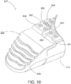
- cartridge (437) comprises a stepped staple deck (448).
- Stepped staple deck (448) includes regions or areas of staple deck (448) that define different planes of staple deck (448) such that staple apertures along staple deck (448) may be located along different planes that face anvil (418).
- cartridge (437) may be fitted with staples of varying lengths. For instance an outer row of staples may be longer compared to the staples used closer to a centerline of cartridge (437). This may promote better stapling of tissue having a thickness that varies across the width of end effector (412).
- cartridge (437) comprises stepped staple deck (448) that defines three separate planes.
- a first plane is defined by an outer region (452) of staple deck (448).
- the first plane and outer region (452) are common to both sides of staple deck (448) such that the outer region on one side of staple deck (448) is co-planar with the outer region on the other side of staple deck (448).
- a second plane is defined by a middle region (454) of staple deck (448).
- the second plane and middle region (454) are common to both sides of staple deck (448) such that the middle region on one side of staple deck (448) is co-planar with the middle region on the other side of staple deck (448).
- a third plane is defined by an inner region (456) of staple deck (448).
- the third plane and inner region (456) are common to both sides of staple deck (448) such that the inner region on one side of staple deck (448) is co-planar with the inner region on the other side of staple deck (448).
- cartridge (437) may be modified similar to cartridge (337) above by having cartridge (437) include a staple deck that defines a single plane such that all staple apertures are located along the same plane facing anvil (418).
- anvil body (420) may have recessed areas along an outer region of anvil body (420) as described above with respect to anvil body (320).
- anvil (418) may comprise anvil body (420) having a flat area along the portion of anvil body (420) having staple forming pockets as described above with respect to anvil body (321) of FIG. 12 .
- various modifications and other ways to configure anvil (418) will be apparent to those of ordinary skill in the art.
- anvil body (420) may have a complementary stepped underside surface to maintain a consistent gap between anvil (418) and cartridge (437) when end effector (412) is closed.
- anvil body (420) may be stepped or not stepped such that a consistent gap is not required across the lateral width of anvil (418) and cartridge (437).
- end effector (412) is configured such that nose (444) of cartridge (437) extends distal to anvil tip (419) when end effector (412) is closed in a non-loaded state.
- anvil tip (419) may deflect when contacting or clamping tissue. In its deflected state, anvil tip (419) may extend distally such that anvil tip (419) aligns with the distal end of nose (444) of cartridge (437), or in some versions extends distally past the distal end of nose (444).
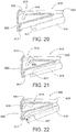
- FIG. 14 illustrates another exemplary end effector (512) comprising anvil (518) and lower jaw (516).
- end effector (512) may be used in place of end effector (12) of instrument (10).
- End effector (512) may be integrally formed with instrument (10) or in the alternative may be interchangeable with end effector (12) of instrument (10).
- Anvil (518) is operable to pivot relative to lower jaw (516).
- Anvil (518) and lower jaw (516) may clamp tissue (90) similarly to clamping performed by anvil (18) and lower jaw (16) shown in FIG. 1 .
- End effector (512) further comprises a cartridge (537) that is operable to be placed in lower jaw (516) similarly to cartridge (37) shown in FIG. 3 .
- Anvil (518) is similar to anvils (318, 418) described above.
- Anvil (518) comprises an anvil body (520) and an anvil tip (519).
- Anvil (518) has an elongated shape where anvil body (520) is straight and anvil tip (519) extends distally in an angled or curved manner toward cartridge (537).
- anvil tip (519) is shaped similar to an inverted ski tip. This may provide easier insertion of end effector (512) into a surgical site.
- the gentle slope or inverted ski tip shape of anvil tip (519) may provide an atraumatic tissue deflection surface as anvil (518) contacts or moves through tissue.
- the angled shape of anvil tip (519) may provide better maneuverability of end effector (512).
- Other suitable variations of anvil (518) will be apparent to one of ordinary skill in the art in view of the teachings herein.
- Anvil (518) further comprises staple forming pockets (not shown) as described above, and a longitudinal anvil slot (not shown) as also described above.
- anvil tip (519) is configured as a modular releasable component that selectively connects with or attaches to anvil body (520).
- anvil tip (519) comprises a fastener (not shown) such as an insert, shim, or other structure that extends proximally and is configured to be received within a distal end of the longitudinal slot.
- Anvil tip (519) comprises a bottom surface (524) that faces cartridge (537) and that is configured to contact tissue (90) when end effector (512) is in a loaded state clamping tissue (90).
- anvil tip (519) comprises one or more features (526) that are configured to also contact tissue (90) when end effector (512) is in a loaded state.
- one or more features (526) comprise a single raised rib that generally extends transversely across a width of anvil tip (519). In this manner, the raised rib protrudes or extends from bottom surface (524) toward cartridge (537). While the present example shows only a single rib, in other versions anvil tip (519) comprises greater or fewer ribs.
- one or more features (526) are positioned along a distal end of anvil tip (519) rather than along a more proximal portion of anvil tip (519).
- the rib is configured such that anvil tip (519) distally terminates at the rib.
- one or more features (526) are not required to be at the distal end of anvil tip (519), and can instead or in addition be located along a more proximal portion of bottom surface (524) of anvil tip (519).
- anvil tip (519) comprises a steeper angle or greater amount of curvature compared to anvil tip (319), but less than that compared to anvil tip (419).
- a longitudinal axis defined by anvil body (520), and a longitudinal axis defined by a distal portion of anvil tip (519) intersect to form an angle of between about 130 degrees and about 150 degrees.
- the same angle with anvil tip (319) and body (320) is greater as the angle of anvil tip (319) relative to anvil body (320) is more gradual.
- the same angle with anvil tip (419) and body (420) is less as the angle of anvil tip (419) relative to anvil body (420) is steeper. Still with any of these anvil tips (319,419, 519) these angles may be larger or smaller as those of ordinary skill in the art will understand in view of the teachings herein.
- Anvil tip (519) is comprised of an elastomeric material in the present example. With such a construction, in use during clamping tissue anvil tip (519) may deflect or bend from a curved state to a straight or less curved state.
- tip (519) may be deflectable between about 20 degrees and about 70 degrees in a downward direction from a longitudinal axis toward cartridge; between about 0 degrees and about 90 degrees in an upward direction from a longitudinal axis toward cartridge (537). The degree of deflection may be influenced by the thickness and/or density of the tissue that is being compressed between anvil (518) and cartridge (537).
- anvil tip (319) may deflect or bend from a curved state to a straight or less curved state in accordance with at least some of the teachings in U.S. Pat. App. No. [ATTORNEY DOCKET NO. END8115USNP.0641880], entitled “Surgical Stapler with Elastically Deformable Tip,” filed on even date herewith, the disclosure of which is incorporated by reference herein.
- anvil tip (519) is operably configured for use in procedures where marching is used.
- one or more features (526) are similarly formed of an elastomeric material such that they are also elastically deformable.
- one or more features (526) are elastically deformable to a different extent than anvil tip (519) generally.
- one or more features (526) can be elastically deformable to the same or to a greater extent compared to anvil tip (519) generally.
- various ways to modify and manipulate the degree or extent of elastic deformability of one or more features (526) and/or anvil tip (519) generally will be apparent to those of ordinary skill in the art.
- anvil tip (519) and/or its one or more features (526) are not required to be elastically deformable and thus may be rigid.
- Cartridge (537) is operable to hold staples similar to staples (47) shown in FIG. 4A for driving into tissue.
- cartridge (537) comprises a nose portion (544) at a distal end.
- Cartridge nose (544) has a triangular profile.
- cartridge nose (544) comprises an upper tapered surface (539), a bottom surface (540), and side surfaces (542).
- bottom surface (540) is generally parallel with a longitudinal axis defined by cartridge (537).
- bottom surface (540) is angled toward the longitudinal axis defined by cartridge (537), similar to the configuration shown above with respect to cartridge (237).
- cartridge (537) comprises one or more features (546) that are configured to also contact tissue (90) when end effector (512) is in a loaded state.
- one or more features (546) comprise a pair of raised ribs that generally extend transversely across a width of cartridge (537). In this manner, the raised ribs protrude or extend from upper surface (539) toward anvil tip (519). While the present example shows two such ribs, in other versions nose portion (544) of cartridge (537) comprises greater or fewer ribs. Also, in the present example, one or more features (546) are positioned along or closer to a middle and distal end of nose portion (544) rather than along a proximal end of nose portion (544). In some other versions, however, one or more features (546) can be located along a proximal end, or other portions of upper surface (539) of cartridge (537).
- cartridge (537) and one or more features (546) protruding from nose portion (544) are rigid such that they do not elastically deform when end effector (512) is in a loaded state clamping tissue (90). Furthermore, when end effector (512) is closed and in a non-loaded state not clamping tissue, one or more features (546) of cartridge (537) are configured to complement one or more features (526) of anvil tip (519). In this manner, when tissue (90) is not present within end effector (512), one or more features (546) of cartridge (537) and one or more features (526) of anvil tip (519) cooperate to form a nesting arrangement.
- one or more features (526) of anvil tip (519) are positionable adjacent to one or more features (546) of cartridge (537).
- the single distal rib of anvil tip (519) is positioned in alignment between two ribs of cartridge (537).
- the single distal rib of anvil tip (519) can be positioned proximal or distal the two ribs of cartridge (537).
- end effector (512) comprises the combination of elastically deformable anvil tip (519) having one or more features (526) combined with rigid cartridge nose (544) having one or more features (546). Furthermore, as described above the one or more features (526) cooperate with, or are complementary to, the one or more features (546).
- one or more features (546) of cartridge nose (544) can be configured as elastically deformable while one or more features (526) of anvil tip (519) can be configured as rigid. Still yet in other versions, both of one or more features (526, 546) can be elastically deformable, or both can be rigid.
- end effector (512) bottom surface (524) of anvil tip (519) and upper surface (539) of cartridge nose portion (544) are angled to different degrees such that surfaces (524, 539) are not parallel.
- end effector (512) comprises a void space (514) between anvil tip (519) and upper surface (539) of cartridge (537).
- void space (514) has a triangular profile.
- FIG. 14 is described as one or more features (526) of anvil tip (519) and one or more features (546) of cartridge nose (544) adopting a nesting arrangement
- such an arrangement is a non-contacting arrangement where even when end effector (512) is closed and in an unloaded state where no tissue is within end effector (512), one or more features (526) of anvil tip (519) do not contact cartridge (537); and similarly one or more features (546) of cartridge nose (544) do not contact anvil tip (519).
- end effector (512) may have a nesting arrangement that is a contacting arrangement where one or more features (526) of anvil tip (519) contact with upper surface (539) of cartridge nose (544) when end effector (512) is closed and in an unloaded state and/or one or more features (546) of cartridge nose (544) contact with bottom surface (524) of anvil tip (519) when end effector (512) is closed and in an unloaded state.
- one or more features (526, 546) contact tissue in a manner that applies staggered concentrations of force to clamped tissue (90). These staggered concentrations of force coincide with the locations where one or more features (526, 546) that protrude from respective anvil tip (519) and cartridge nose (544) contact tissue (90).
- one or more features (526, 546) also provide a tissue stop or locking feature that inhibits tissue (90) that is clamped between anvil (518) and cartridge (537) from spilling over the end of end effector (512).
- end effector (512) may be rotated before, during, or after clamping tissue (90).
- the curved shape of anvil (518) may also provide more accessible viewing of anvil tip (519) or regions substantially adjacent anvil tip (519).
- the curve of anvil (518) may further promote easy insertion of end effector (512) into tissue in an atraumatic manner.
- it may be easier to fit end effector (512) through a trocar or other devices operable to introduce end effector (512) into a surgical site due to the curve of anvil (518) of end effector (512).
- cartridge (537) comprises vertical slot (not shown) having the same or similar structure and function as vertical slot (49) discussed above.
- Cartridge (537) also comprises staple apertures (not shown) having the same or similar structure and function as staple apertures (51) discussed above.
- cartridge (537) is generally flat along a staple deck (548) with staple apertures being along the same plane defined by staple deck (548).
- cartridge (537) comprises shelf (550), which is also flat but is slightly recessed relative to staple deck (548).
- cartridge (537) may be modified similar to cartridge (37) above by having cartridge (537) include separate raised areas and recessed areas such that one row of staple apertures may be higher or lower than another row of staple apertures.
- staple deck (548) of cartridge (537) could be modified so that staple deck (548) defines more than one plane and staple apertures are not all along the same plane, but instead are found of different planes facing anvil (518), the same or similar to that described above for cartridge (437).
- anvil body (520) may have recessed areas along an outer region of anvil body (520) as described above with respect to anvil body (320).
- anvil (518) may comprise anvil body (520) having a flat area along the portion of anvil body (520) having staple forming pockets as described above with respect to anvil body (321) of FIG. 12 .
- various modifications and other ways to configure anvil (518) will be apparent to those of ordinary skill in the art.
- anvil body (520) may have a complementary stepped underside surface to maintain a consistent gap between anvil (518) and cartridge (537) when end effector (512) is closed.
- anvil body (520) may be stepped or not stepped such that a consistent gap is not required across the lateral width of anvil (518) and cartridge (537).
- end effector (512) is configured such that nose (544) of cartridge (537) extends distal to anvil tip (519) when end effector (512) is closed in a non-loaded state.
- elastically deformable anvil tip (519) may deflect when contacting or clamping tissue. In its deflected state, anvil tip (519) may extend distally such that anvil tip (519) remains proximal to the distal end of cartridge nose (544). In other examples anvil tip (519) may extend when deflected to align with the distal end of nose (544) of cartridge (537). Still in other examples, anvil tip (519) may extend when deflected distally past the distal end of nose (544).
- FIG. 15 illustrates another exemplary end effector (612) comprising anvil (618) and lower jaw (616).
- end effector (612) may be used in place of end effector (12) of instrument (10).
- End effector (612) may be integrally formed with instrument (10) or in the alternative may be interchangeable with end effector (12) of instrument (10).
- Anvil (618) is operable to pivot relative to lower jaw (616).
- Anvil (618) and lower jaw (616) may clamp tissue (90) similarly to clamping performed by anvil (18) and lower jaw (16) shown in FIG. 1 .
- End effector (612) further comprises a cartridge (637) that is operable to be placed in lower jaw (616) similarly to cartridge (37) shown in FIG. 3 .
- Anvil (618) is similar to anvil (418) described above.
- Anvil (618) comprises an anvil body (620) and an anvil tip (619).
- Anvil (618) has an elongated shape where anvil body (620) is straight and anvil tip (619) extends distally in an angled or curved manner toward cartridge (637).
- anvil tip (619) is shaped similar to an inverted ski tip. This may provide easier insertion of end effector (612) into a surgical site.
- the gentle slope or inverted ski tip shape of anvil tip (619) may provide an atraumatic tissue deflection surface as anvil (618) contacts or moves through tissue.
- the angled shape of anvil tip (619) may provide better maneuverability of end effector (612).
- Other suitable variations of anvil (618) will be apparent to one of ordinary skill in the art in view of the teachings herein.
- Anvil (618) further comprises staple forming pockets (not shown) as described above, and a longitudinal anvil slot (42) as also described above.
- anvil tip (619) is configured as a modular releasable component that selectively connects with or attaches to anvil body (620).
- anvil tip (619) comprises a fastener (634) such as an insert, shim, or other structure that extends proximally and is configured to be received within a distal end of longitudinal slot (42).
- Anvil tip (619) comprises a bottom surface (624) that faces cartridge (637) and that is configured to contact tissue (90) when end effector (612) is in a loaded state clamping tissue (90).
- anvil tip (619) comprises one or more features (626) that are configured to also contact tissue (90) when end effector (612) is in a loaded state.
- one or more features (626) comprise a recessed area in the form of a circular depression (i.e., a concave spherical dome) in bottom surface (624) of anvil tip (619). While the present example shows a single recessed area in the form of a circular depression, in other versions anvil tip (519) may comprise more than one recessed area that may also have other shapes besides or in addition to a circular depression.
- anvil tip (619) comprises a similar angle or similar amount of curvature compared to anvil tip (319).
- a longitudinal axis defined by anvil body (620), and a longitudinal axis defined by a distal portion of anvil tip (619) intersect to form an angle of between about 135 degrees and about 160 degrees. Still with either anvil tip (319, 619) these angles may be larger or smaller as those of ordinary skill in the art will understand in view of the teachings herein.
- Anvil tip (619) is comprised of an elastomeric material in the present example. With such a construction, in use during clamping tissue anvil tip (619) may deflect or bend from a curved state to a straight or less curved state.
- tip (619) may be deflectable between about 20 degrees and about 70 degrees in a downward direction from a longitudinal axis toward cartridge; between about 0 degrees and about 90 degrees in an upward direction from a longitudinal axis toward cartridge (637). The degree of deflection may be influenced by the thickness and/or density of the tissue that is being compressed between anvil (618) and cartridge (637).
- anvil tip (319) may deflect or bend from a curved state to a straight or less curved state in accordance with at least some of the teachings in U.S. Pat. App. No. [ATTORNEY DOCKET NO. END8115USNP.0641880], entitled “Surgical Stapler with Elastically Deformable Tip,” filed on even date herewith, the disclosure of which is incorporated by reference herein.
- anvil tip (619) is operably configured for use in procedures where marching is used.
- various ways to modify and manipulate the degree or extent of elastic deformability of anvil tip (619) will be apparent to those of ordinary skill in the art. Still in other versions, anvil tip (619) is not required to be elastically deformable and thus may be rigid.
- Cartridge (637) is operable to hold staples similar to staples (47) shown in FIG. 4A for driving into tissue.
- cartridge (637) comprises a nose portion (644) at a distal end.
- Cartridge nose (644) has a triangular profile.
- cartridge nose (644) comprises an upper tapered surface (639), a bottom surface (640), and side surfaces (642).
- bottom surface (640) is generally parallel with a longitudinal axis defined by cartridge (637).
- bottom surface (640) is angled toward the longitudinal axis defined by cartridge (637), similar to the configuration shown above with respect to cartridge (237).
- cartridge (637) comprises one or more features (646) that are configured to also contact tissue (90) when end effector (612) is in a loaded state.
- one or more features (646) comprise a raised member in the form of a dome shaped protrusion (i.e., a convex spherical dome). In this manner, the raised member protrudes or extends from upper surface (639) toward anvil tip (619). While the present example shows one such raised member, in other versions nose portion (644) of cartridge (637) may comprise more than one raised member, and the one or more raised members may take the form of a dome shaped protrusion or another shape that will be apparent to those of ordinary skill in the art in view of the teachings herein.
- feature (626) is concave in the present example and feature (646) is convex in the present example, it should be understood that this structural relationship may be reversed. In other words, in some variations feature (626) is convex and feature (646) is concave.
- cartridge (637) and one or more features (646) protruding from nose portion (644) are rigid such that they do not elastically deform when end effector (612) is in a loaded state clamping tissue (90). Furthermore, when end effector (612) is closed and in a non-loaded state not clamping tissue, one or more features (646) of cartridge (637) are configured to complement one or more features (626) of anvil tip (619). In this manner, when tissue (90) is not present within end effector (612), one or more features (646) of cartridge (637) and one or more features (626) of anvil tip (619) cooperate to form a nesting arrangement.
- one or more features (626) of anvil tip (619) are positionable adjacent to one or more features (646) of cartridge (637).
- the dome shaped protrusion of cartridge nose (644) is posited within the space defined by circular depression of anvil tip (419).
- end effector (612) comprises the combination of elastically deformable anvil tip (619) having one or more features (626) combined with rigid cartridge nose (644) having one or more features (646). Furthermore, as described above the one or more features (626) cooperate with, or are complementary to, the one or more features (646).
- one or more features (646) of cartridge nose (644) can be configured as elastically deformable while one or more features (626) of anvil tip (619) can be configured as rigid. Still yet in other versions, both of one or more features (626, 646) can be elastically deformable, or both can be rigid.
- bottom surface (624) of anvil tip (619) and upper surface (639) of cartridge nose portion (644) are nearly parallel surfaces. This orientation promotes a general close spacing between bottom surface (624) and upper surface (639) when end effector (612) is closed and in a non-loaded state.
- other arrangements for the orientation of bottom surface (624) and upper surface (639), including other non-parallel arrangements or parallel arrangements, will be apparent to those of ordinary skill in the art.
- FIG. 15 is described as one or more features (626) of anvil tip (619) and one or more features (646) of cartridge nose (644) adopting a nesting arrangement, in some instances, such as the illustrated version, this arrangement is a non-contacting arrangement.
- this arrangement is a non-contacting arrangement.
- neither anvil tip (619) nor one or more features (626) of anvil tip (619) contacts with upper surface (639) of cartridge nose (644) when end effector (612) is closed and in an unloaded state, and similarly one or more features (646) of cartridge nose (644) do not contact anvil tip (619).
- the nesting arrangement may be a contacting arrangement where anvil tip (619) and/or one or more features (626) of anvil tip (619) contacts with upper surface (639) of cartridge nose (644) when end effector (612) is closed and in an unloaded state and/or one or more features (646) of cartridge nose (644) contact with bottom surface (624) of anvil tip (619) when end effector (612) is closed and in an unloaded state.
- one or more features (626, 646) contact tissue in a manner that applies force to clamped tissue (90).
- anvil tip (619) and cartridge nose (644) are used in marching applications, when tissue (90) is clamped between a closed cartridge (637) and anvil (618), a user would be able to determine whether they are at the final cut and staple location along the tissue since at that point the one or more features (626, 646) may adopt their nested arrangement or a partially nested arrangement. In either arrangement, a portion of the dome shaped protrusion would reside within the space of the circular depression. This could be detected by the user visually in a non-contacting arrangement and visually and/or based on tactile feedback from prior cut and staple iterations in a contacting arrangement where dome shaped protrusion contacts circular depression.
- the one or more features (626, 646) also provide a tissue stop or locking feature that inhibits or restricts tissue (90) that is clamped between anvil (618) and cartridge (637) from spilling over the end of end effector (612).
- end effector (612) may be rotated before, during, or after clamping tissue (90).
- the curved shape of anvil (618) may also provide more accessible viewing of anvil tip (619) or regions substantially adjacent anvil tip (619).
- the curve of anvil (618) may further promote easy insertion of end effector (612) into tissue in an atraumatic manner.
- it may be easier to fit end effector (612) through a trocar or other devices operable to introduce end effector (612) into a surgical site due to the curve of anvil (618) of end effector (612).
- cartridge (637) comprises vertical slot (not shown) having the same or similar structure and function as vertical slot (49) discussed above.
- Cartridge (637) also comprises staple apertures (not shown) having the same or similar structure and function as staple apertures (51) discussed above.
- cartridge (637) comprises a stepped staple deck (648).
- Stepped staple deck (648) includes regions or areas of staple deck (648) that define different planes of staple deck (648) such that staple apertures along staple deck (648) may be located along different planes facing anvil (618).
- cartridge (637) may be fitted with staples of varying lengths. For instance an outer row of staples may be longer compared to the staples used closer to a centerline of cartridge (637).
- cartridge (637) comprises stepped staple deck (648) that defines three separate planes.
- a first plane is defined by an outer region (652) of staple deck (648).
- the first plane and outer region (652) are common to both sides of staple deck (648) such that the outer region on one side of staple deck (648) is co-planar with the outer region on the other side of staple deck (648).
- a second plane is defined by a middle region (654) of staple deck (648).
- the second plane and middle region (654) are common to both sides of staple deck (648) such that the middle region on one side of staple deck (648) is co-planar with the middle region on the other side of staple deck (648).
- a third plane is defined by an inner region (656) of staple deck (648).
- the third plane and inner region (656) are common to both sides of staple deck (648) such that the inner region on one side of staple deck (648) is co-planar with the inner region on the other side of staple deck (648).
- cartridge (637) may be modified similar to cartridge (337) above by having cartridge (637) include a staple deck that defines a single plane such that all staple apertures are located along the same plane facing anvil (618).
- anvil body (620) may have recessed areas along an outer region of anvil body (620) as described above with respect to anvil body (320).
- anvil (618) may comprise anvil body (620) having a flat area along the portion of anvil body (620) having staple forming pockets as described above with respect to anvil body (321) of FIG. 12 .
- various modifications and other ways to configure anvil (618) will be apparent to those of ordinary skill in the art.
- anvil body (620) may have a complementary stepped underside surface to maintain a consistent gap between anvil (618) and cartridge (637) when end effector (612) is closed.
- anvil body (620) may be stepped or not stepped such that a consistent gap is not required across the lateral width of anvil (618) and cartridge (637).
- end effector (612) is configured such that a distal end of anvil tip (619) extends distal to cartridge nose (644) when end effector (612) is closed in a non-loaded state.
- anvil tip (619) may deflect when contacting or clamping tissue. In its deflected state, anvil tip (619) may extend further distally such that anvil tip (619) extends further past the distal end of cartridge nose (644) when end effector (612) clamps tissue.
- end effector (612) may be configured such that the distal end of anvil tip (619) aligns with the distal end of cartridge nose (644), or anvil tip (619) may be proximal to the distal end of cartridge nose (644).
- FIGS. 16 and 17 illustrate another exemplary end effector (712) comprising anvil (718) and lower jaw (716).
- end effector (712) may be used in place of end effector (12) of instrument (10).
- End effector (712) may be integrally formed with instrument (10) or in the alternative may be interchangeable with end effector (12) of instrument (10).
- Anvil (718) is operable to pivot relative to lower jaw (716).
- Anvil (718) and lower jaw (716) may clamp tissue (90) similarly to clamping performed by anvil (18) and lower jaw (16) shown in FIG. 1 .
- End effector (712) further comprises a cartridge (737) that is operable to be placed in lower jaw (716) similarly to cartridge (37) shown in FIG. 3 .
- Anvil (718) is identical to anvil (418) described above except as noted as follows. Accordingly, the description above of anvil (418) applies equally here to anvil (718), with any differences described below with respect to FIGS. 16 and 17 . Additionally, cartridge (737) and lower jaw (716) are identical to cartridge (337) and lower jaw (316) except as noted as follows. Accordingly, the description above of cartridge (337) and lower jaw (316) applies equally here to cartridge (737) and lower jaw (716), with any differences described below with respect to FIGS. 16 and 17 .
- anvil tip (719) comprises one or more features (726) that are configured to also contact tissue (90) when end effector (712) is in a loaded state.
- one or more features (726) comprise a pair of raised ribs that generally extend transversely across a width of anvil tip (719) in a curved arrangement.
- cartridge (737) comprises one or more features (746) configured to also contact tissue (90) when end effector (712) is in a loaded state.
- one or more features (746) comprise a single raised rib having a U-shape or a horseshoe shape or configuration and generally extending transversely across a width of cartridge (737) as shown in FIG. 17 .
- one or more features (746) of cartridge (737) are configured to complement one or more features (726) of anvil tip (719).
- one or more features (746) of cartridge (737) and one or more features (726) of anvil tip (719) cooperate to form a nesting arrangement.
- one or more features (726) of anvil tip (719) are positionable adjacent to one or more features (746) of cartridge (737).
- the one or more features (726) of anvil (719) surround the one or more features (746) of cartridge (737) with end effector (712) closed and in a non-loaded state.
- the one or more features (726) of anvil (719) complement the one or more features (746) of cartridge (737) as described above with respect to end effector (412) for example.
- end effector (712) is configured such that nose (344) of cartridge (737) extends distal to anvil tip (719) when end effector (712) is closed in a non-loaded state.
- anvil tip (719) may deflect when contacting or clamping tissue. In its deflected state, anvil tip (719) may extend distally such that anvil tip (719) aligns with the distal end of nose (344) of cartridge (737), or in some versions extends distally past the distal end of nose (344).
- FIG. 18 illustrates a portion of another exemplary cartridge (837) and lower jaw (816) that may be used with any of the end effectors described herein.
- cartridge (837) is compatible with the lower jaws of the end effectors described herein.
- Cartridge (837) and lower jaw (816) are identical to cartridge (337) and lower jaw (316) except as noted as follows. Accordingly, the description above of cartridge (337) and lower jaw (316) applies equally here to cartridge (837) and lower jaw (816), with any differences described below with respect to FIG. 18 .
- Cartridge (837) comprises staple deck (848) that includes surface features (858).
- Surface features (858) are configured to provide enhanced tissue gripping during clamping, cutting, and stapling.
- a pair of surface features (858) are located at opposite ends of each staple forming aperture (351) in staple deck (848).
- each of surface features (858) comprises a U-shape or horseshoe shape having ends (862) that face each other.
- Staple forming apertures (351) are arranged in rows where each row's staple forming apertures (351) are offset from staple forming apertures (351) of an adjacent row.
- surface features (858) are likewise arranged in rows where each row's surface features (858) are offset from surface features (858) of an adjacent row.
- surface features (858) are located and configured to provide enhance gripping of tissue at or immediately adjacent to the locations where staples will ultimately pass through tissue to seal or connect cut tissue.
- surface features (858) promote achieving a high quality and successful application of stapling to tissue.
- other ways to configure surface features (858) will be apparent to those of ordinary skill in the art.
- Cartridge (837) further comprises upper tapered surface (839) that includes surface features (860).
- Surface features (860) are similar to one or more features (346, 446, 546, 746) described above.
- the complementary features cooperate as described above in e.g. end effector (312).
- the anvil used with cartridge (837) may not include features that complement surface features (860).
- Surface features (860) are configured to provide enhanced tissue gripping during clamping, cutting, and stapling of tissue.
- surface features (860) are configured as raised ribs having a nested sinusoidal arrangement. While in the present example there are five surface features (860), in other versions the number of surfaces features (860) may be greater or fewer. In view of the teaching herein, other shapes and arrangements for surface features (860) will be apparent to those of ordinary skill in the art.
- Both surface features (858) and surface features (860) are rigid in the present example, but in other versions either or both of surface features (858, 860) may be elastically deformable.
- the anvil of the end effector is the movable jaw portion of the end effector while the cartridge is the fixed or non-movable jaw portion of the end effector.
- the modular and elastically deformable anvil tips shown and described herein are attachable or connectable with the movable jaw portion of such end effectors.
- modular and elastically deformable tips such as those configurations described herein, can be adapted or modified to be tips for the cartridge or non-movable jaw portion of the end effector.
- modifications to end effectors will be apparent to those of ordinary skill in the art in view of the teachings herein.
- the anvil may remain stationary relative to the shaft assembly while the jaw portion holding the staples pivots toward and away from the fixed anvil.
- an instrument with an end effector having an anvil tip and staple cartridge that have cooperating features it can be useful to provide for a device that aids in installation of the anvil tip to the anvil of the end effector while also simultaneously aiding in the installation of the staple cartridge to the lower jaw of the end effector.
- a device can be useful in marching procedures where replacement staple cartridges are installed sequentially during a cutting and stapling procedure.
- Such a device can also be helpful to ensure that matching anvil tips and staple cartridges are installed together so the full benefit of the cooperating features of each can be realized.
- FIG. 19 illustrates an exemplary device, in the form of a loading cartridge (900), for installing an anvil tip (919) and a staple cartridge (937) to an end effector (912) of FIG. 20 .
- some loading cartridges (900) may be configured for use with end effectors (312, 412, 512, 612, 712) as well as other end effectors that will be apparent to those of ordinary skill in the art in view of the teachings herein.
- loading cartridge (900) is further configured to aid in removing a previously installed or existing anvil tip (919) and/or a previously installed or existing staple cartridge (937) from end effector (912).
- Loading cartridge (900) may be considered as installing a new anvil tip and staple cartridge for a first use of an end effector, or loading cartridge (900) may be considered as installing a replacement anvil tip and/or replacement cartridge.
- loading cartridge (900) comprises a housing (902), a removal side (904), and an installation side (906). Positioned within installation side (906), is anvil tip (919).
- anvil tip (919) comprises a body portion (908) and a shim (910).
- anvil tip (919) is configured for installation within an anvil as shown and described in U.S. Pat. App. No. [ATTORNEY DOCKET NO. END8116USNP.0641882] entitled "Surgical Stapler with Insertable Distal Anvil Tip,” filed on even date herewith, and the disclosure of which is incorporated by reference herein.
- anvil tip configurations suitable for use with cartridge (900) will be apparent to those of ordinary skill in the art in view of the teachings herein.
- other anvil tips that may be used with loading cartridge (900) or another similar cartridge include anvil tips (319, 419, 519, 619, 719).
- cartridge (937) that is configured to hold one or more staples.
- Cartridge (937) may be the same or similar to any of those staple cartridges described herein.
- other cartridges that may be used with loading cartridge (900) include cartridges (337, 437, 537, 637, 737, 837).
- Various other staple cartridge configurations suitable for use with loading cartridge (900) will be apparent to those of ordinary skill in the art in view of the teachings herein.
- loading cartridge (900) comprises a top side (911) and a bottom side (914).
- anvil tip (919) is selectively retained within top side (911), while cartridge (937) is selectively retained within bottom side (914).
- shim (910) is selectively retained within a clamp member (915). Shim (910) further extends partially within body portion (908) of anvil tip (919) to selectively retain body portion (908) within top side (911) of installation side (906) of loading cartridge (900). As shown best in FIGS.
- loading cartridge (900) comprises a clamp member (917) along bottom side (914) that is configured to selectively engage with a distal end of cartridge (937) to selectively retain cartridge (937) within bottom side (914) of installation side (906) of loading cartridge (900).
- proximal portions of loading cartridge (900) may be configured as engaging portions that selectively engage with the vertical slot (949) of staple cartridge (937) to promote further selective retention of cartridge (937) within loading cartridge (900).
- installation side (906) of loading cartridge (900) to provide selective retention of anvil tip (919) and cartridge (937) will be apparent to those of ordinary skill in the art.
- guide members (924) are located along top side (911) of installation side (906).
- Guide members (924) are configured to guide end effector (912) being used with loading cartridge (900).
- guide members (924) provide a cam action to guide anvil (918) of end effector (912) into position to receive anvil tip (919).
- guide members (924) also provide a cam action to guide lower jaw (916) of end effector (912) into position to receive staple cartridge (937).
- Loading cartridge (900) comprises removal side (904) as mentioned above.
- Removal side (904) like installation side (906), is divided into two compartments (921, 922).
- Compartment (921) is located along top side (911) of loading cartridge (900), while compartment (922) is located along a bottom side (914) of cartridge (900).
- Hooks (926) are resiliently biased such that when anvil tip (919), such as a previously installed anvil tip (919), of end effector (912) is inserted within compartment (921) and advanced distally toward a distal end (930) of loading cartridge (900), hooks (926) deflect away from the inserted and advancing anvil tip (919). This deflection of hooks (926) permits continued advancing of anvil tip (919) distally.
- Top side (911) of removal side (904) is further configured such that when anvil tip (919) is fully positioned within removal side (904), hooks (926) resiliently return to their initial non-deflected, or a less deflected, state such that hooks (926) can engage with body portion (908) of anvil tip (919).
- Removal side (904) comprises hook (928) as well.
- Hook (928) is configured to engage shim (910) of anvil tip (919) being removed.
- shim (910) being engaged for removal may be from a previously installed anvil tip (919).
- Hook (928) is also resiliently biased in the present example. This resilient bias allows for hook (928) to deflect away from anvil tip (919) when anvil (918) is inserted within removal side (906).
- hook (928) comprises a chamfer (932) that is configured to promote deflection of hook (928) when contacted from a proximal side and a force is applied distally.
- anvil tip (919) is configured such that body portion (908) comprises a space (not shown) beneath shim (910) when anvil tip (919) is fully installed on anvil (918) and shim (910) is fully posited within body portion (908). This space allows for hook (928) to contact shim (910), and when deflected downwardly to slide past shim (910).
- hook (928) resiliently returns to its initial non-deflected, or a less deflected, state such that hook (928) can engage with the head portion of shim (910).
- the space for receiving hook (928) may be located within a distal end of shim (910) itself, rather than within body portion (908).
- end effector (912) can be retracted from removal side (904) and hook (928) will hold shim (910) stationary such that shim (910) is pulled free from a longitudinal slot (not shown) of anvil body (920).
- hooks (926) will hold anvil body portion (908) stationary relative to retracting end effector (912). Consequently, the retention of shim (910) and anvil body portion (908) during retraction of end effector (912) from removal side (904) causes removal of anvil tip (919) from anvil body (920) of anvil (918) of end effector (912).
- Removal side (904) also includes compartment (922) along bottom side (914). Compartment (922) provides for a space within which a previously installed staple cartridge (937) is removable.
- a distal end of bottom side (914) of removal side (904) comprises a resilient clamp member (not shown), similar to clamp member (917) mentioned above.
- the resilient clamp member on removal side (904) is configurable such that it engages with a distal end of cartridge (937) when end effector (912) is fully advanced within removal side (904). With the clamp member engaged with the distal end of staple cartridge (937), end effector (912) can be opened such that lower jaw (916) moves downwardly and away from loading cartridge (900).
- loading cartridge (900) may include features operable to remove and/or secure anvil tips (910) from/to anvil body (920). Examples of such features are described in U.S. Patent App. No. [ATTORNEY DOCKET NO. END8116USNP.0641882], entitled “Surgical Stapler with Insertable Distal Anvil Tip,” filed on even date herewith, the disclosure of which is incorporated by reference herein.
- guide members (934) Similar to installation side (906), within removal side (904) are guide members (934).
- guide members (934) are located along top side (911) of removal side (904).
- Guide members (934) are configured to guide end effector (912) being used with loading cartridge (900).
- guide members (934) provide a camming action to guide anvil (918) of end effector (912) into position to remove anvil tip (919).
- guide members (934) also provide a camming action to guide lower jaw (916) of end effector (912) into position to remove staple cartridge (937).
- FIGS. 20-22 illustrate an exemplary series view showing use of loading cartridge (900) to install anvil tip (919) and staple cartridge (937) with end effector (912).
- end effector (912) is opened to some extent and anvil (918) is aligned and slid within installation side (906).
- guide members (924) assist in the alignment of anvil (918) when inserting or sliding anvil (918) within top side (911) of installation side (906).
- lower jaw (916) is initially empty such that it can receive cartridge (937).
- end effector (312) is aligned with anvil (918) within top side (911) of installation side (906), and lower jaw (916) within bottom side (914) of installation side (906)
- end effector (912) is advanced distally and closed slightly.
- anvil (918) is moved distally to position an insert portion of anvil body portion (908) within the longitudinal slot of anvil body (920).
- lower jaw (916) moves distally and closes to some extent such that cartridge (937) partially resides within lower jaw (916) as shown in FIG. 21 .
- end effector (912) is then advanced further distally relative to loading cartridge (900) such that shim (910) is inserted through anvil body portion (908) and into the longitudinal slot of anvil body (920).
- anvil tip (919) is now securely connected with anvil body (920).
- lower jaw (916) moves distally and closes further such lower jaw (916) engages cartridge (937) such that cartridge (937) is now securely connected with lower jaw (916).
- end effector (912) is retracted from loading cartridge (900) and ready for use.
- loading cartridge (900) for use with any of the end effectors described herein, will be apparent to those of ordinary skill in the art.
- other ways to use loading cartridge (900) or a modified loading cartridge (900) with the end effectors described herein to remove or install anvil tips and/or staple cartridges will be apparent to those of ordinary skill in the art.
- An apparatus comprising: (a) a body portion; (b) a shaft extending distally from the body portion, wherein the shaft defines a longitudinal axis; and (c) an end effector in communication with the shaft, wherein the end effector is movable between an open configuration and a closed configuration, wherein the end effector is operable to compress, staple, and cut tissue, and wherein the end effector comprises: (i) a cartridge configured to hold one or more staples, wherein the cartridge comprises an angled nose portion, wherein the angled nose portion comprises one or more first features protruding from the nose portion, wherein the one or more first features are configured to contact tissue, (ii) an anvil body, and (iii) an anvil tip configured to be selectively secured with a distal end of the anvil body, wherein the anvil tip comprises a curved portion, wherein the curved portion comprises one or more second features configured to contact tissue, wherein the one or more first features of the cartridge are configured to complement the one or more second features of the
- Example 1 The apparatus of Example 1, wherein at least a portion of the anvil tip is elastically deformable and configured to deflect in response to a clamping force applied to the anvil tip.
- Example 4 The apparatus of Example 4, wherein the one or more first features of the cartridge are rigid.
- Example 9 The apparatus of Example 9, wherein a select proximal-most one of the one or more first features of the cartridge are positioned proximal to the one or more second features of the anvil tip.
- Example 11 The apparatus of Example 11, wherein a select proximal-most one of the one or more first features of the cartridge are positioned proximal to the one or more second features of the anvil tip.
- Example 13 The apparatus of Example 13, wherein the anvil tip extends distal to the nose of the cartridge.
- the apparatus further comprises a shim configured to connect the anvil tip with the anvil body, wherein the shim is selectively insertable within the slot of the anvil body.
- An apparatus comprising: (a) a body portion; (b) a shaft extending distally from the body portion, wherein the shaft defines a longitudinal axis; and (c) an end effector in communication with the shaft, wherein the end effector is movable between an open configuration and a closed configuration, wherein the end effector is operable to compress, staple, and cut tissue, and wherein the end effector comprises: (i) a lower jaw configured to receive and selectively retain a first cartridge configured to hold one or more staples, wherein the first cartridge comprises an angled nose portion, wherein the angled nose portion comprises one or more first features protruding from the nose portion, wherein the one or more first features are configured to contact tissue, (ii) an anvil body configured to receive and selectively retain an anvil tip, wherein the anvil tip comprises a curved portion, wherein the curved portion comprises one or more second features configured to contact tissue, wherein the one or more first features of the first cartridge are configured to complement the one or more second features of the anvil tip
- Example 17 The apparatus of Example 17, wherein the second cartridge is further configured to remove the anvil tip and the first cartridge from the end effector, wherein the second cartridge is further configured to install a replacement anvil tip and a replacement first cartridge.
- Example 18 The apparatus of Example 18, wherein the second cartridge comprises a compartment configured to receive the anvil tip, wherein the second cartridge further comprises one or more hook members configured to engage with the anvil tip to retain the anvil tip within the compartment as the end effector is separated from the second cartridge, thereby removing the anvil tip from the end effector.
- a method of configuring a surgical instrument for use comprising: (i) a body portion, (ii) a shaft extending distally from the body portion, and (iii) an end effector in communication with the shaft, wherein the end effector is operable to compress, staple, and cut tissue, wherein the end effector comprises an anvil body configured to receive an anvil tip, and wherein the end effector comprises a lower jaw configured to receive a first cartridge that is configured to hold one or more staples; wherein the method steps comprise: (a) aligning the end effector with a second cartridge, wherein the second cartridge selectively retains the anvil tip and the first cartridge, wherein first cartridge comprises a nose portion having one or more first features, wherein the anvil tip comprises a curved portion having one or more second features, wherein the one or more first features of the first cartridge are configured to complement the one or more second features of the anvil tip; (b) inserting an anvil body of the end effector into an upper compartment of the second cartridge; (c
- 2012/0132450 entitled “Shiftable Drive Interface for Robotically-Controlled Surgical Tool,” published May 31, 2012, the disclosure of which is incorporated by reference herein;
- U.S. Pub. No. 2012/0199633 entitled “Surgical Stapling Instruments with Cam-Driven Staple Deployment Arrangements,” published August 9, 2012, the disclosure of which is incorporated by reference herein;
- U.S. Pub. No. 2012/0199631 entitled “Robotically-Controlled Motorized Surgical End Effector System with Rotary Actuated Closure Systems Having Variable Actuation Speeds,” published August 9, 2012, the disclosure of which is incorporated by reference herein;
- 2012/0138660 entitled “Robotically-Controlled Cable-Based Surgical End Effectors,” published June 7, 2012, the disclosure of which is incorporated by reference herein; and/or U.S. Pub. No. 2012/0205421 , entitled “Robotically-Controlled Surgical End Effector System with Rotary Actuated Closure Systems,” published August 16,2012, the disclosure of which is incorporated by reference herein.
- Versions of the devices described above may be designed to be disposed of after a single use, or they can be designed to be used multiple times. Versions may, in either or both cases, be reconditioned for reuse after at least one use. Reconditioning may include any combination of the steps of disassembly of the device, followed by cleaning or replacement of particular pieces, and subsequent reassembly. In particular, some versions of the device may be disassembled, and any number of the particular pieces or parts of the device may be selectively replaced or removed in any combination. Upon cleaning and/or replacement of particular parts, some versions of the device may be reassembled for subsequent use either at a reconditioning facility, or by a user immediately prior to a procedure.
- reconditioning of a device may utilize a variety of techniques for disassembly, cleaning/replacement, and reassembly. Use of such techniques, and the resulting reconditioned device, are all within the scope of the present application.
- versions described herein may be sterilized before and/or after a procedure.
- the device is placed in a closed and sealed container, such as a plastic or TYVEK bag.
- the container and device may then be placed in a field of radiation that can penetrate the container, such as gamma radiation, x-rays, or high-energy electrons.
- the radiation may kill bacteria on the device and in the container.
- the sterilized device may then be stored in the sterile container for later use.
- a device may also be sterilized using any other technique known in the art, including but not limited to beta or gamma radiation, ethylene oxide, or steam.
Landscapes
- Health & Medical Sciences (AREA)
- Life Sciences & Earth Sciences (AREA)
- Surgery (AREA)
- Heart & Thoracic Surgery (AREA)
- Engineering & Computer Science (AREA)
- Biomedical Technology (AREA)
- Nuclear Medicine, Radiotherapy & Molecular Imaging (AREA)
- Medical Informatics (AREA)
- Molecular Biology (AREA)
- Animal Behavior & Ethology (AREA)
- General Health & Medical Sciences (AREA)
- Public Health (AREA)
- Veterinary Medicine (AREA)
- Surgical Instruments (AREA)
Applications Claiming Priority (1)
| Application Number | Priority Date | Filing Date | Title |
|---|---|---|---|
| US15/435,618 US10806451B2 (en) | 2017-02-17 | 2017-02-17 | Surgical stapler with cooperating distal tip features on anvil and staple cartridge |
Publications (3)
| Publication Number | Publication Date |
|---|---|
| EP3363384A2 true EP3363384A2 (fr) | 2018-08-22 |
| EP3363384A3 EP3363384A3 (fr) | 2018-10-31 |
| EP3363384B1 EP3363384B1 (fr) | 2020-10-28 |
Family
ID=61231153
Family Applications (1)
| Application Number | Title | Priority Date | Filing Date |
|---|---|---|---|
| EP18157199.3A Active EP3363384B1 (fr) | 2017-02-17 | 2018-02-16 | Agrafeuse chirurgicale présentant des caractéristiques de pointe distale coopérantes sur l'enclume et la cartouche d'agrafes |
Country Status (6)
| Country | Link |
|---|---|
| US (1) | US10806451B2 (fr) |
| EP (1) | EP3363384B1 (fr) |
| JP (1) | JP7237841B2 (fr) |
| CN (1) | CN110520062B (fr) |
| BR (1) | BR112019016978A2 (fr) |
| WO (1) | WO2018152151A1 (fr) |
Cited By (2)
| Publication number | Priority date | Publication date | Assignee | Title |
|---|---|---|---|---|
| EP3607891A3 (fr) * | 2018-07-16 | 2020-04-22 | Ethicon LLC | Composant d'effecteur d'extrémité d'agrafage chirurgical avec pointe déformable dotée d'une extrémité distale épaisse |
| EP3733083A1 (fr) * | 2019-04-30 | 2020-11-04 | Ethicon LLC | Pointe de mâchoire rotative pour un instrument chirurgical |
Families Citing this family (349)
| Publication number | Priority date | Publication date | Assignee | Title |
|---|---|---|---|---|
| US20070084897A1 (en) | 2003-05-20 | 2007-04-19 | Shelton Frederick E Iv | Articulating surgical stapling instrument incorporating a two-piece e-beam firing mechanism |
| US9060770B2 (en) | 2003-05-20 | 2015-06-23 | Ethicon Endo-Surgery, Inc. | Robotically-driven surgical instrument with E-beam driver |
| US9072535B2 (en) | 2011-05-27 | 2015-07-07 | Ethicon Endo-Surgery, Inc. | Surgical stapling instruments with rotatable staple deployment arrangements |
| US11890012B2 (en) | 2004-07-28 | 2024-02-06 | Cilag Gmbh International | Staple cartridge comprising cartridge body and attached support |
| US11998198B2 (en) | 2004-07-28 | 2024-06-04 | Cilag Gmbh International | Surgical stapling instrument incorporating a two-piece E-beam firing mechanism |
| US8215531B2 (en) | 2004-07-28 | 2012-07-10 | Ethicon Endo-Surgery, Inc. | Surgical stapling instrument having a medical substance dispenser |
| US7669746B2 (en) | 2005-08-31 | 2010-03-02 | Ethicon Endo-Surgery, Inc. | Staple cartridges for forming staples having differing formed staple heights |
| US9237891B2 (en) | 2005-08-31 | 2016-01-19 | Ethicon Endo-Surgery, Inc. | Robotically-controlled surgical stapling devices that produce formed staples having different lengths |
| US11484312B2 (en) | 2005-08-31 | 2022-11-01 | Cilag Gmbh International | Staple cartridge comprising a staple driver arrangement |
| US10159482B2 (en) | 2005-08-31 | 2018-12-25 | Ethicon Llc | Fastener cartridge assembly comprising a fixed anvil and different staple heights |
| US11246590B2 (en) | 2005-08-31 | 2022-02-15 | Cilag Gmbh International | Staple cartridge including staple drivers having different unfired heights |
| US7934630B2 (en) | 2005-08-31 | 2011-05-03 | Ethicon Endo-Surgery, Inc. | Staple cartridges for forming staples having differing formed staple heights |
| US20070106317A1 (en) | 2005-11-09 | 2007-05-10 | Shelton Frederick E Iv | Hydraulically and electrically actuated articulation joints for surgical instruments |
| US8186555B2 (en) | 2006-01-31 | 2012-05-29 | Ethicon Endo-Surgery, Inc. | Motor-driven surgical cutting and fastening instrument with mechanical closure system |
| US7845537B2 (en) | 2006-01-31 | 2010-12-07 | Ethicon Endo-Surgery, Inc. | Surgical instrument having recording capabilities |
| US8820603B2 (en) | 2006-01-31 | 2014-09-02 | Ethicon Endo-Surgery, Inc. | Accessing data stored in a memory of a surgical instrument |
| US11278279B2 (en) | 2006-01-31 | 2022-03-22 | Cilag Gmbh International | Surgical instrument assembly |
| US20110295295A1 (en) | 2006-01-31 | 2011-12-01 | Ethicon Endo-Surgery, Inc. | Robotically-controlled surgical instrument having recording capabilities |
| US20120292367A1 (en) | 2006-01-31 | 2012-11-22 | Ethicon Endo-Surgery, Inc. | Robotically-controlled end effector |
| US11793518B2 (en) | 2006-01-31 | 2023-10-24 | Cilag Gmbh International | Powered surgical instruments with firing system lockout arrangements |
| US7753904B2 (en) | 2006-01-31 | 2010-07-13 | Ethicon Endo-Surgery, Inc. | Endoscopic surgical instrument with a handle that can articulate with respect to the shaft |
| US11224427B2 (en) | 2006-01-31 | 2022-01-18 | Cilag Gmbh International | Surgical stapling system including a console and retraction assembly |
| US8708213B2 (en) | 2006-01-31 | 2014-04-29 | Ethicon Endo-Surgery, Inc. | Surgical instrument having a feedback system |
| US20110024477A1 (en) | 2009-02-06 | 2011-02-03 | Hall Steven G | Driven Surgical Stapler Improvements |
| US8992422B2 (en) | 2006-03-23 | 2015-03-31 | Ethicon Endo-Surgery, Inc. | Robotically-controlled endoscopic accessory channel |
| US8322455B2 (en) | 2006-06-27 | 2012-12-04 | Ethicon Endo-Surgery, Inc. | Manually driven surgical cutting and fastening instrument |
| US10568652B2 (en) | 2006-09-29 | 2020-02-25 | Ethicon Llc | Surgical staples having attached drivers of different heights and stapling instruments for deploying the same |
| US11980366B2 (en) | 2006-10-03 | 2024-05-14 | Cilag Gmbh International | Surgical instrument |
| US8684253B2 (en) | 2007-01-10 | 2014-04-01 | Ethicon Endo-Surgery, Inc. | Surgical instrument with wireless communication between a control unit of a robotic system and remote sensor |
| US8632535B2 (en) | 2007-01-10 | 2014-01-21 | Ethicon Endo-Surgery, Inc. | Interlock and surgical instrument including same |
| US11291441B2 (en) | 2007-01-10 | 2022-04-05 | Cilag Gmbh International | Surgical instrument with wireless communication between control unit and remote sensor |
| US11039836B2 (en) | 2007-01-11 | 2021-06-22 | Cilag Gmbh International | Staple cartridge for use with a surgical stapling instrument |
| US7434717B2 (en) | 2007-01-11 | 2008-10-14 | Ethicon Endo-Surgery, Inc. | Apparatus for closing a curved anvil of a surgical stapling device |
| US7669747B2 (en) | 2007-03-15 | 2010-03-02 | Ethicon Endo-Surgery, Inc. | Washer for use with a surgical stapling instrument |
| US11672531B2 (en) | 2007-06-04 | 2023-06-13 | Cilag Gmbh International | Rotary drive systems for surgical instruments |
| US8931682B2 (en) | 2007-06-04 | 2015-01-13 | Ethicon Endo-Surgery, Inc. | Robotically-controlled shaft based rotary drive systems for surgical instruments |
| US7753245B2 (en) | 2007-06-22 | 2010-07-13 | Ethicon Endo-Surgery, Inc. | Surgical stapling instruments |
| US11849941B2 (en) | 2007-06-29 | 2023-12-26 | Cilag Gmbh International | Staple cartridge having staple cavities extending at a transverse angle relative to a longitudinal cartridge axis |
| RU2493788C2 (ru) | 2008-02-14 | 2013-09-27 | Этикон Эндо-Серджери, Инк. | Хирургический режущий и крепежный инструмент, имеющий радиочастотные электроды |
| US11986183B2 (en) | 2008-02-14 | 2024-05-21 | Cilag Gmbh International | Surgical cutting and fastening instrument comprising a plurality of sensors to measure an electrical parameter |
| US7819298B2 (en) | 2008-02-14 | 2010-10-26 | Ethicon Endo-Surgery, Inc. | Surgical stapling apparatus with control features operable with one hand |
| US7866527B2 (en) | 2008-02-14 | 2011-01-11 | Ethicon Endo-Surgery, Inc. | Surgical stapling apparatus with interlockable firing system |
| US8636736B2 (en) | 2008-02-14 | 2014-01-28 | Ethicon Endo-Surgery, Inc. | Motorized surgical cutting and fastening instrument |
| US9179912B2 (en) | 2008-02-14 | 2015-11-10 | Ethicon Endo-Surgery, Inc. | Robotically-controlled motorized surgical cutting and fastening instrument |
| US8573465B2 (en) | 2008-02-14 | 2013-11-05 | Ethicon Endo-Surgery, Inc. | Robotically-controlled surgical end effector system with rotary actuated closure systems |
| US9615826B2 (en) | 2010-09-30 | 2017-04-11 | Ethicon Endo-Surgery, Llc | Multiple thickness implantable layers for surgical stapling devices |
| US11648005B2 (en) | 2008-09-23 | 2023-05-16 | Cilag Gmbh International | Robotically-controlled motorized surgical instrument with an end effector |
| US8210411B2 (en) | 2008-09-23 | 2012-07-03 | Ethicon Endo-Surgery, Inc. | Motor-driven surgical cutting instrument |
| US9005230B2 (en) | 2008-09-23 | 2015-04-14 | Ethicon Endo-Surgery, Inc. | Motorized surgical instrument |
| US9386983B2 (en) | 2008-09-23 | 2016-07-12 | Ethicon Endo-Surgery, Llc | Robotically-controlled motorized surgical instrument |
| US8608045B2 (en) | 2008-10-10 | 2013-12-17 | Ethicon Endo-Sugery, Inc. | Powered surgical cutting and stapling apparatus with manually retractable firing system |
| US8517239B2 (en) | 2009-02-05 | 2013-08-27 | Ethicon Endo-Surgery, Inc. | Surgical stapling instrument comprising a magnetic element driver |
| BRPI1008667A2 (pt) | 2009-02-06 | 2016-03-08 | Ethicom Endo Surgery Inc | aperfeiçoamento do grampeador cirúrgico acionado |
| US8851354B2 (en) | 2009-12-24 | 2014-10-07 | Ethicon Endo-Surgery, Inc. | Surgical cutting instrument that analyzes tissue thickness |
| US8783543B2 (en) | 2010-07-30 | 2014-07-22 | Ethicon Endo-Surgery, Inc. | Tissue acquisition arrangements and methods for surgical stapling devices |
| US9386988B2 (en) | 2010-09-30 | 2016-07-12 | Ethicon End-Surgery, LLC | Retainer assembly including a tissue thickness compensator |
| US9861361B2 (en) | 2010-09-30 | 2018-01-09 | Ethicon Llc | Releasable tissue thickness compensator and fastener cartridge having the same |
| US10945731B2 (en) | 2010-09-30 | 2021-03-16 | Ethicon Llc | Tissue thickness compensator comprising controlled release and expansion |
| US11812965B2 (en) | 2010-09-30 | 2023-11-14 | Cilag Gmbh International | Layer of material for a surgical end effector |
| US9839420B2 (en) | 2010-09-30 | 2017-12-12 | Ethicon Llc | Tissue thickness compensator comprising at least one medicament |
| US11298125B2 (en) | 2010-09-30 | 2022-04-12 | Cilag Gmbh International | Tissue stapler having a thickness compensator |
| US11925354B2 (en) | 2010-09-30 | 2024-03-12 | Cilag Gmbh International | Staple cartridge comprising staples positioned within a compressible portion thereof |
| US9629814B2 (en) | 2010-09-30 | 2017-04-25 | Ethicon Endo-Surgery, Llc | Tissue thickness compensator configured to redistribute compressive forces |
| US9016542B2 (en) | 2010-09-30 | 2015-04-28 | Ethicon Endo-Surgery, Inc. | Staple cartridge comprising compressible distortion resistant components |
| US8695866B2 (en) | 2010-10-01 | 2014-04-15 | Ethicon Endo-Surgery, Inc. | Surgical instrument having a power control circuit |
| RU2606493C2 (ru) | 2011-04-29 | 2017-01-10 | Этикон Эндо-Серджери, Инк. | Кассета со скобками, содержащая скобки, расположенные внутри ее сжимаемой части |
| US11207064B2 (en) | 2011-05-27 | 2021-12-28 | Cilag Gmbh International | Automated end effector component reloading system for use with a robotic system |
| BR112014024098B1 (pt) | 2012-03-28 | 2021-05-25 | Ethicon Endo-Surgery, Inc. | cartucho de grampos |
| CN104321024B (zh) | 2012-03-28 | 2017-05-24 | 伊西康内外科公司 | 包括多个层的组织厚度补偿件 |
| RU2644272C2 (ru) | 2012-03-28 | 2018-02-08 | Этикон Эндо-Серджери, Инк. | Узел ограничения, включающий компенсатор толщины ткани |
| US9101358B2 (en) | 2012-06-15 | 2015-08-11 | Ethicon Endo-Surgery, Inc. | Articulatable surgical instrument comprising a firing drive |
| US9289256B2 (en) | 2012-06-28 | 2016-03-22 | Ethicon Endo-Surgery, Llc | Surgical end effectors having angled tissue-contacting surfaces |
| US9282974B2 (en) | 2012-06-28 | 2016-03-15 | Ethicon Endo-Surgery, Llc | Empty clip cartridge lockout |
| BR112014032776B1 (pt) | 2012-06-28 | 2021-09-08 | Ethicon Endo-Surgery, Inc | Sistema de instrumento cirúrgico e kit cirúrgico para uso com um sistema de instrumento cirúrgico |
| US20140001234A1 (en) | 2012-06-28 | 2014-01-02 | Ethicon Endo-Surgery, Inc. | Coupling arrangements for attaching surgical end effectors to drive systems therefor |
| US20140001231A1 (en) | 2012-06-28 | 2014-01-02 | Ethicon Endo-Surgery, Inc. | Firing system lockout arrangements for surgical instruments |
| CN104487005B (zh) | 2012-06-28 | 2017-09-08 | 伊西康内外科公司 | 空夹仓闭锁件 |
| US11197671B2 (en) | 2012-06-28 | 2021-12-14 | Cilag Gmbh International | Stapling assembly comprising a lockout |
| US9700310B2 (en) | 2013-08-23 | 2017-07-11 | Ethicon Llc | Firing member retraction devices for powered surgical instruments |
| BR112015021082B1 (pt) | 2013-03-01 | 2022-05-10 | Ethicon Endo-Surgery, Inc | Instrumento cirúrgico |
| JP6382235B2 (ja) | 2013-03-01 | 2018-08-29 | エシコン・エンド−サージェリィ・インコーポレイテッドEthicon Endo−Surgery,Inc. | 信号通信用の導電路を備えた関節運動可能な外科用器具 |
| US9629629B2 (en) | 2013-03-14 | 2017-04-25 | Ethicon Endo-Surgey, LLC | Control systems for surgical instruments |
| US9649110B2 (en) | 2013-04-16 | 2017-05-16 | Ethicon Llc | Surgical instrument comprising a closing drive and a firing drive operated from the same rotatable output |
| BR112015026109B1 (pt) | 2013-04-16 | 2022-02-22 | Ethicon Endo-Surgery, Inc | Instrumento cirúrgico |
| JP6416260B2 (ja) | 2013-08-23 | 2018-10-31 | エシコン エルエルシー | 動力付き外科用器具のための発射部材後退装置 |
| BR112016021943B1 (pt) | 2014-03-26 | 2022-06-14 | Ethicon Endo-Surgery, Llc | Instrumento cirúrgico para uso por um operador em um procedimento cirúrgico |
| US9826977B2 (en) | 2014-03-26 | 2017-11-28 | Ethicon Llc | Sterilization verification circuit |
| BR112016023807B1 (pt) | 2014-04-16 | 2022-07-12 | Ethicon Endo-Surgery, Llc | Conjunto de cartucho de prendedores para uso com um instrumento cirúrgico |
| JP6636452B2 (ja) | 2014-04-16 | 2020-01-29 | エシコン エルエルシーEthicon LLC | 異なる構成を有する延在部を含む締結具カートリッジ |
| US20150297225A1 (en) | 2014-04-16 | 2015-10-22 | Ethicon Endo-Surgery, Inc. | Fastener cartridges including extensions having different configurations |
| BR112016023825B1 (pt) | 2014-04-16 | 2022-08-02 | Ethicon Endo-Surgery, Llc | Cartucho de grampos para uso com um grampeador cirúrgico e cartucho de grampos para uso com um instrumento cirúrgico |
| US10327764B2 (en) | 2014-09-26 | 2019-06-25 | Ethicon Llc | Method for creating a flexible staple line |
| BR112017004361B1 (pt) | 2014-09-05 | 2023-04-11 | Ethicon Llc | Sistema eletrônico para um instrumento cirúrgico |
| US11311294B2 (en) | 2014-09-05 | 2022-04-26 | Cilag Gmbh International | Powered medical device including measurement of closure state of jaws |
| US10016199B2 (en) | 2014-09-05 | 2018-07-10 | Ethicon Llc | Polarity of hall magnet to identify cartridge type |
| US10105142B2 (en) | 2014-09-18 | 2018-10-23 | Ethicon Llc | Surgical stapler with plurality of cutting elements |
| BR112017005981B1 (pt) | 2014-09-26 | 2022-09-06 | Ethicon, Llc | Material de escora para uso com um cartucho de grampos cirúrgicos e cartucho de grampos cirúrgicos para uso com um instrumento cirúrgico |
| US11523821B2 (en) | 2014-09-26 | 2022-12-13 | Cilag Gmbh International | Method for creating a flexible staple line |
| US9924944B2 (en) | 2014-10-16 | 2018-03-27 | Ethicon Llc | Staple cartridge comprising an adjunct material |
| US10517594B2 (en) | 2014-10-29 | 2019-12-31 | Ethicon Llc | Cartridge assemblies for surgical staplers |
| US11141153B2 (en) | 2014-10-29 | 2021-10-12 | Cilag Gmbh International | Staple cartridges comprising driver arrangements |
| US9844376B2 (en) | 2014-11-06 | 2017-12-19 | Ethicon Llc | Staple cartridge comprising a releasable adjunct material |
| US10736636B2 (en) | 2014-12-10 | 2020-08-11 | Ethicon Llc | Articulatable surgical instrument system |
| US9987000B2 (en) | 2014-12-18 | 2018-06-05 | Ethicon Llc | Surgical instrument assembly comprising a flexible articulation system |
| US10085748B2 (en) | 2014-12-18 | 2018-10-02 | Ethicon Llc | Locking arrangements for detachable shaft assemblies with articulatable surgical end effectors |
| BR112017012996B1 (pt) | 2014-12-18 | 2022-11-08 | Ethicon Llc | Instrumento cirúrgico com uma bigorna que é seletivamente móvel sobre um eixo geométrico imóvel distinto em relação a um cartucho de grampos |
| US9844375B2 (en) | 2014-12-18 | 2017-12-19 | Ethicon Llc | Drive arrangements for articulatable surgical instruments |
| US9968355B2 (en) | 2014-12-18 | 2018-05-15 | Ethicon Llc | Surgical instruments with articulatable end effectors and improved firing beam support arrangements |
| US9844374B2 (en) | 2014-12-18 | 2017-12-19 | Ethicon Llc | Surgical instrument systems comprising an articulatable end effector and means for adjusting the firing stroke of a firing member |
| US11154301B2 (en) | 2015-02-27 | 2021-10-26 | Cilag Gmbh International | Modular stapling assembly |
| JP2020121162A (ja) | 2015-03-06 | 2020-08-13 | エシコン エルエルシーEthicon LLC | 測定の安定性要素、クリープ要素、及び粘弾性要素を決定するためのセンサデータの時間依存性評価 |
| US10245033B2 (en) | 2015-03-06 | 2019-04-02 | Ethicon Llc | Surgical instrument comprising a lockable battery housing |
| US10441279B2 (en) | 2015-03-06 | 2019-10-15 | Ethicon Llc | Multiple level thresholds to modify operation of powered surgical instruments |
| US9993248B2 (en) | 2015-03-06 | 2018-06-12 | Ethicon Endo-Surgery, Llc | Smart sensors with local signal processing |
| US10052044B2 (en) | 2015-03-06 | 2018-08-21 | Ethicon Llc | Time dependent evaluation of sensor data to determine stability, creep, and viscoelastic elements of measures |
| US10390825B2 (en) | 2015-03-31 | 2019-08-27 | Ethicon Llc | Surgical instrument with progressive rotary drive systems |
| US10238386B2 (en) | 2015-09-23 | 2019-03-26 | Ethicon Llc | Surgical stapler having motor control based on an electrical parameter related to a motor current |
| US10105139B2 (en) | 2015-09-23 | 2018-10-23 | Ethicon Llc | Surgical stapler having downstream current-based motor control |
| US10299878B2 (en) | 2015-09-25 | 2019-05-28 | Ethicon Llc | Implantable adjunct systems for determining adjunct skew |
| US10524788B2 (en) | 2015-09-30 | 2020-01-07 | Ethicon Llc | Compressible adjunct with attachment regions |
| US11890015B2 (en) | 2015-09-30 | 2024-02-06 | Cilag Gmbh International | Compressible adjunct with crossing spacer fibers |
| US10980539B2 (en) | 2015-09-30 | 2021-04-20 | Ethicon Llc | Implantable adjunct comprising bonded layers |
| US10433846B2 (en) | 2015-09-30 | 2019-10-08 | Ethicon Llc | Compressible adjunct with crossing spacer fibers |
| US10292704B2 (en) | 2015-12-30 | 2019-05-21 | Ethicon Llc | Mechanisms for compensating for battery pack failure in powered surgical instruments |
| US10368865B2 (en) | 2015-12-30 | 2019-08-06 | Ethicon Llc | Mechanisms for compensating for drivetrain failure in powered surgical instruments |
| US11213293B2 (en) | 2016-02-09 | 2022-01-04 | Cilag Gmbh International | Articulatable surgical instruments with single articulation link arrangements |
| JP6911054B2 (ja) | 2016-02-09 | 2021-07-28 | エシコン エルエルシーEthicon LLC | 非対称の関節構成を備えた外科用器具 |
| US11224426B2 (en) | 2016-02-12 | 2022-01-18 | Cilag Gmbh International | Mechanisms for compensating for drivetrain failure in powered surgical instruments |
| US10448948B2 (en) | 2016-02-12 | 2019-10-22 | Ethicon Llc | Mechanisms for compensating for drivetrain failure in powered surgical instruments |
| US11607239B2 (en) | 2016-04-15 | 2023-03-21 | Cilag Gmbh International | Systems and methods for controlling a surgical stapling and cutting instrument |
| US10426467B2 (en) | 2016-04-15 | 2019-10-01 | Ethicon Llc | Surgical instrument with detection sensors |
| US10357247B2 (en) | 2016-04-15 | 2019-07-23 | Ethicon Llc | Surgical instrument with multiple program responses during a firing motion |
| US10335145B2 (en) | 2016-04-15 | 2019-07-02 | Ethicon Llc | Modular surgical instrument with configurable operating mode |
| US10828028B2 (en) | 2016-04-15 | 2020-11-10 | Ethicon Llc | Surgical instrument with multiple program responses during a firing motion |
| US11179150B2 (en) | 2016-04-15 | 2021-11-23 | Cilag Gmbh International | Systems and methods for controlling a surgical stapling and cutting instrument |
| US10492783B2 (en) | 2016-04-15 | 2019-12-03 | Ethicon, Llc | Surgical instrument with improved stop/start control during a firing motion |
| US10456137B2 (en) | 2016-04-15 | 2019-10-29 | Ethicon Llc | Staple formation detection mechanisms |
| US10363037B2 (en) | 2016-04-18 | 2019-07-30 | Ethicon Llc | Surgical instrument system comprising a magnetic lockout |
| US20170296173A1 (en) | 2016-04-18 | 2017-10-19 | Ethicon Endo-Surgery, Llc | Method for operating a surgical instrument |
| US11317917B2 (en) | 2016-04-18 | 2022-05-03 | Cilag Gmbh International | Surgical stapling system comprising a lockable firing assembly |
| US10542981B2 (en) | 2016-11-14 | 2020-01-28 | Ethicon Llc | Atraumatic stapling head features for circular surgical stapler |
| US10667810B2 (en) | 2016-12-21 | 2020-06-02 | Ethicon Llc | Closure members with cam surface arrangements for surgical instruments with separate and distinct closure and firing systems |
| US10537325B2 (en) | 2016-12-21 | 2020-01-21 | Ethicon Llc | Staple forming pocket arrangement to accommodate different types of staples |
| US10542982B2 (en) | 2016-12-21 | 2020-01-28 | Ethicon Llc | Shaft assembly comprising first and second articulation lockouts |
| US10758230B2 (en) | 2016-12-21 | 2020-09-01 | Ethicon Llc | Surgical instrument with primary and safety processors |
| US10624635B2 (en) | 2016-12-21 | 2020-04-21 | Ethicon Llc | Firing members with non-parallel jaw engagement features for surgical end effectors |
| US10610224B2 (en) | 2016-12-21 | 2020-04-07 | Ethicon Llc | Lockout arrangements for surgical end effectors and replaceable tool assemblies |
| US11419606B2 (en) | 2016-12-21 | 2022-08-23 | Cilag Gmbh International | Shaft assembly comprising a clutch configured to adapt the output of a rotary firing member to two different systems |
| CN110087565A (zh) | 2016-12-21 | 2019-08-02 | 爱惜康有限责任公司 | 外科缝合系统 |
| JP7010956B2 (ja) | 2016-12-21 | 2022-01-26 | エシコン エルエルシー | 組織をステープル留めする方法 |
| US11134942B2 (en) | 2016-12-21 | 2021-10-05 | Cilag Gmbh International | Surgical stapling instruments and staple-forming anvils |
| US10517596B2 (en) | 2016-12-21 | 2019-12-31 | Ethicon Llc | Articulatable surgical instruments with articulation stroke amplification features |
| CN110099619B (zh) | 2016-12-21 | 2022-07-15 | 爱惜康有限责任公司 | 用于外科端部执行器和可替换工具组件的闭锁装置 |
| JP7086963B2 (ja) | 2016-12-21 | 2022-06-20 | エシコン エルエルシー | エンドエフェクタロックアウト及び発射アセンブリロックアウトを備える外科用器具システム |
| US20180168615A1 (en) | 2016-12-21 | 2018-06-21 | Ethicon Endo-Surgery, Llc | Method of deforming staples from two different types of staple cartridges with the same surgical stapling instrument |
| US11564687B2 (en) | 2017-02-17 | 2023-01-31 | Cilag Gmbh International | Method of surgical stapling with end effector component having a curved tip |
| US11272930B2 (en) | 2017-02-17 | 2022-03-15 | Cilag Gmbh International | Method of surgical stapling with end effector component having a curved tip |
| US11103244B2 (en) | 2017-02-17 | 2021-08-31 | Cilag Gmbh International | Surgical stapling end effector jaw with tip deflecting toward other jaw |
| US11564684B2 (en) | 2017-02-17 | 2023-01-31 | Cilag Gmbh International | Surgical stapling end effector component with tip having varying bend angle |
| US10307170B2 (en) | 2017-06-20 | 2019-06-04 | Ethicon Llc | Method for closed loop control of motor velocity of a surgical stapling and cutting instrument |
| US10881399B2 (en) | 2017-06-20 | 2021-01-05 | Ethicon Llc | Techniques for adaptive control of motor velocity of a surgical stapling and cutting instrument |
| US10779820B2 (en) | 2017-06-20 | 2020-09-22 | Ethicon Llc | Systems and methods for controlling motor speed according to user input for a surgical instrument |
| US11071554B2 (en) | 2017-06-20 | 2021-07-27 | Cilag Gmbh International | Closed loop feedback control of motor velocity of a surgical stapling and cutting instrument based on magnitude of velocity error measurements |
| US11382638B2 (en) | 2017-06-20 | 2022-07-12 | Cilag Gmbh International | Closed loop feedback control of motor velocity of a surgical stapling and cutting instrument based on measured time over a specified displacement distance |
| US11090046B2 (en) | 2017-06-20 | 2021-08-17 | Cilag Gmbh International | Systems and methods for controlling displacement member motion of a surgical stapling and cutting instrument |
| US11517325B2 (en) | 2017-06-20 | 2022-12-06 | Cilag Gmbh International | Closed loop feedback control of motor velocity of a surgical stapling and cutting instrument based on measured displacement distance traveled over a specified time interval |
| US11653914B2 (en) | 2017-06-20 | 2023-05-23 | Cilag Gmbh International | Systems and methods for controlling motor velocity of a surgical stapling and cutting instrument according to articulation angle of end effector |
| US11324503B2 (en) | 2017-06-27 | 2022-05-10 | Cilag Gmbh International | Surgical firing member arrangements |
| US11266405B2 (en) | 2017-06-27 | 2022-03-08 | Cilag Gmbh International | Surgical anvil manufacturing methods |
| US20180368844A1 (en) | 2017-06-27 | 2018-12-27 | Ethicon Llc | Staple forming pocket arrangements |
| US10993716B2 (en) | 2017-06-27 | 2021-05-04 | Ethicon Llc | Surgical anvil arrangements |
| US11564686B2 (en) | 2017-06-28 | 2023-01-31 | Cilag Gmbh International | Surgical shaft assemblies with flexible interfaces |
| US11478242B2 (en) | 2017-06-28 | 2022-10-25 | Cilag Gmbh International | Jaw retainer arrangement for retaining a pivotable surgical instrument jaw in pivotable retaining engagement with a second surgical instrument jaw |
| US11259805B2 (en) | 2017-06-28 | 2022-03-01 | Cilag Gmbh International | Surgical instrument comprising firing member supports |
| US10765427B2 (en) | 2017-06-28 | 2020-09-08 | Ethicon Llc | Method for articulating a surgical instrument |
| EP3420947B1 (fr) | 2017-06-28 | 2022-05-25 | Cilag GmbH International | Instrument chirurgical comprenant des coupleurs rotatifs actionnables de façon sélective |
| USD906355S1 (en) | 2017-06-28 | 2020-12-29 | Ethicon Llc | Display screen or portion thereof with a graphical user interface for a surgical instrument |
| US10779824B2 (en) | 2017-06-28 | 2020-09-22 | Ethicon Llc | Surgical instrument comprising an articulation system lockable by a closure system |
| US11246592B2 (en) | 2017-06-28 | 2022-02-15 | Cilag Gmbh International | Surgical instrument comprising an articulation system lockable to a frame |
| US10932772B2 (en) | 2017-06-29 | 2021-03-02 | Ethicon Llc | Methods for closed loop velocity control for robotic surgical instrument |
| US11944300B2 (en) | 2017-08-03 | 2024-04-02 | Cilag Gmbh International | Method for operating a surgical system bailout |
| US11471155B2 (en) | 2017-08-03 | 2022-10-18 | Cilag Gmbh International | Surgical system bailout |
| US11974742B2 (en) | 2017-08-03 | 2024-05-07 | Cilag Gmbh International | Surgical system comprising an articulation bailout |
| US11304695B2 (en) | 2017-08-03 | 2022-04-19 | Cilag Gmbh International | Surgical system shaft interconnection |
| US10743872B2 (en) | 2017-09-29 | 2020-08-18 | Ethicon Llc | System and methods for controlling a display of a surgical instrument |
| US11399829B2 (en) | 2017-09-29 | 2022-08-02 | Cilag Gmbh International | Systems and methods of initiating a power shutdown mode for a surgical instrument |
| US11134944B2 (en) | 2017-10-30 | 2021-10-05 | Cilag Gmbh International | Surgical stapler knife motion controls |
| US11207066B2 (en) * | 2017-10-30 | 2021-12-28 | Covidien Lp | Apparatus for endoscopic procedures |
| US11090075B2 (en) | 2017-10-30 | 2021-08-17 | Cilag Gmbh International | Articulation features for surgical end effector |
| US10842490B2 (en) | 2017-10-31 | 2020-11-24 | Ethicon Llc | Cartridge body design with force reduction based on firing completion |
| US11071543B2 (en) | 2017-12-15 | 2021-07-27 | Cilag Gmbh International | Surgical end effectors with clamping assemblies configured to increase jaw aperture ranges |
| US11197670B2 (en) | 2017-12-15 | 2021-12-14 | Cilag Gmbh International | Surgical end effectors with pivotal jaws configured to touch at their respective distal ends when fully closed |
| US10779826B2 (en) | 2017-12-15 | 2020-09-22 | Ethicon Llc | Methods of operating surgical end effectors |
| US10835330B2 (en) | 2017-12-19 | 2020-11-17 | Ethicon Llc | Method for determining the position of a rotatable jaw of a surgical instrument attachment assembly |
| US11311290B2 (en) | 2017-12-21 | 2022-04-26 | Cilag Gmbh International | Surgical instrument comprising an end effector dampener |
| US11076853B2 (en) | 2017-12-21 | 2021-08-03 | Cilag Gmbh International | Systems and methods of displaying a knife position during transection for a surgical instrument |
| US11883019B2 (en) | 2017-12-21 | 2024-01-30 | Cilag Gmbh International | Stapling instrument comprising a staple feeding system |
| US10973515B2 (en) | 2018-07-16 | 2021-04-13 | Ethicon Llc | Permanent attachment means for curved tip of component of surgical stapling instrument |
| US11160550B2 (en) | 2018-07-16 | 2021-11-02 | Cilag Gmbh International | Surgical stapling end effector component with articulation and asymmetric deformable tip |
| US10912561B2 (en) | 2018-07-16 | 2021-02-09 | Ethicon Llc | Buttress applier cartridge for surgical stapler having end effector with deflectable curved tip |
| US11179154B2 (en) | 2018-07-16 | 2021-11-23 | Cilag Gmbh International | Surgical stapling end effector component with deformable tip skewing in multiple planes |
| US10786252B2 (en) | 2018-07-16 | 2020-09-29 | Ethicon Llc | Surgical stapling end effector component with deformable tip having void |
| USD914878S1 (en) | 2018-08-20 | 2021-03-30 | Ethicon Llc | Surgical instrument anvil |
| US11045192B2 (en) | 2018-08-20 | 2021-06-29 | Cilag Gmbh International | Fabricating techniques for surgical stapler anvils |
| US11291440B2 (en) | 2018-08-20 | 2022-04-05 | Cilag Gmbh International | Method for operating a powered articulatable surgical instrument |
| US11253256B2 (en) | 2018-08-20 | 2022-02-22 | Cilag Gmbh International | Articulatable motor powered surgical instruments with dedicated articulation motor arrangements |
| US11039834B2 (en) | 2018-08-20 | 2021-06-22 | Cilag Gmbh International | Surgical stapler anvils with staple directing protrusions and tissue stability features |
| US11207065B2 (en) | 2018-08-20 | 2021-12-28 | Cilag Gmbh International | Method for fabricating surgical stapler anvils |
| US11083458B2 (en) | 2018-08-20 | 2021-08-10 | Cilag Gmbh International | Powered surgical instruments with clutching arrangements to convert linear drive motions to rotary drive motions |
| US11324501B2 (en) | 2018-08-20 | 2022-05-10 | Cilag Gmbh International | Surgical stapling devices with improved closure members |
| US11116505B2 (en) | 2018-12-28 | 2021-09-14 | Cilag Gmbh International | Applicator for surgical stapler buttress |
| US11272935B2 (en) | 2018-12-28 | 2022-03-15 | Cilag Gmbh International | Curved tip surgical stapler buttress assembly applicator with opening feature for curved tip alignment |
| US11432817B2 (en) | 2018-12-28 | 2022-09-06 | Cilag Gmbh International | Packaging for surgical stapler buttress |
| USD922576S1 (en) | 2018-12-28 | 2021-06-15 | Cilag Gmbh International | Applicator tray for a buttress applicator for a surgical stapler |
| USD901686S1 (en) | 2018-12-28 | 2020-11-10 | Ethicon Llc | Applicator for surgical stapler buttress |
| US11033269B2 (en) | 2018-12-28 | 2021-06-15 | Cilag Gmbh International | Method of applying buttresses to surgically cut and stapled sites |
| USD903115S1 (en) | 2018-12-28 | 2020-11-24 | Ethicon Llc | Applicator for a surgical stapler buttress |
| US11166725B2 (en) | 2018-12-28 | 2021-11-09 | Cilag Gmbh International | Configuration of buttress for surgical stapler |
| USD932621S1 (en) | 2018-12-28 | 2021-10-05 | Cilag Gmbh International | Buttress assembly for a surgical stapler |
| US11103243B2 (en) | 2018-12-28 | 2021-08-31 | Cilag Gmbh International | Curved tip surgical stapler buttress assembly applicator with compression layer pocket feature |
| US10905424B2 (en) | 2018-12-28 | 2021-02-02 | Ethicon Llc | Curved tip surgical stapler buttress assembly applicator with proximal alignment features |
| US11166724B2 (en) | 2018-12-28 | 2021-11-09 | Cilag Gmbh International | Adhesive distribution on buttress for surgical stapler |
| USD933220S1 (en) | 2018-12-28 | 2021-10-12 | Cilag Gmbh International | Buttress assembly for a surgical stapler |
| USD926318S1 (en) | 2018-12-28 | 2021-07-27 | Cilag Gmbh International | Surgical stapler deck with tissue engagement recess features |
| USD926317S1 (en) | 2018-12-28 | 2021-07-27 | Cilag Gmbh International | Surgical stapler deck with tissue engagement cleat features |
| US11701109B2 (en) | 2018-12-28 | 2023-07-18 | Cilag Gmbh International | Surgical stapler with sloped staple deck for varying tissue compression |
| US11202628B2 (en) | 2018-12-28 | 2021-12-21 | Cilag Gmbh International | Surgical stapler with tissue engagement features around tissue containment pin |
| US11317912B2 (en) | 2019-01-30 | 2022-05-03 | Cilag Gmbh International | Surgical stapler with rotatable distal tip |
| US11439391B2 (en) | 2019-01-30 | 2022-09-13 | Cilag Gmbh International | Surgical stapler with toggling distal tip |
| US11304697B2 (en) | 2019-01-30 | 2022-04-19 | Cilag Gmbh International | Surgical stapler with deflectable distal tip |
| US11147551B2 (en) | 2019-03-25 | 2021-10-19 | Cilag Gmbh International | Firing drive arrangements for surgical systems |
| US11696761B2 (en) | 2019-03-25 | 2023-07-11 | Cilag Gmbh International | Firing drive arrangements for surgical systems |
| US11147553B2 (en) | 2019-03-25 | 2021-10-19 | Cilag Gmbh International | Firing drive arrangements for surgical systems |
| US11172929B2 (en) | 2019-03-25 | 2021-11-16 | Cilag Gmbh International | Articulation drive arrangements for surgical systems |
| US11432816B2 (en) | 2019-04-30 | 2022-09-06 | Cilag Gmbh International | Articulation pin for a surgical instrument |
| US11426251B2 (en) | 2019-04-30 | 2022-08-30 | Cilag Gmbh International | Articulation directional lights on a surgical instrument |
| US11903581B2 (en) | 2019-04-30 | 2024-02-20 | Cilag Gmbh International | Methods for stapling tissue using a surgical instrument |
| US11452528B2 (en) | 2019-04-30 | 2022-09-27 | Cilag Gmbh International | Articulation actuators for a surgical instrument |
| US11253254B2 (en) | 2019-04-30 | 2022-02-22 | Cilag Gmbh International | Shaft rotation actuator on a surgical instrument |
| US11471157B2 (en) | 2019-04-30 | 2022-10-18 | Cilag Gmbh International | Articulation control mapping for a surgical instrument |
| US11627959B2 (en) | 2019-06-28 | 2023-04-18 | Cilag Gmbh International | Surgical instruments including manual and powered system lockouts |
| US11426167B2 (en) | 2019-06-28 | 2022-08-30 | Cilag Gmbh International | Mechanisms for proper anvil attachment surgical stapling head assembly |
| US11298132B2 (en) | 2019-06-28 | 2022-04-12 | Cilag GmbH Inlernational | Staple cartridge including a honeycomb extension |
| US11051807B2 (en) | 2019-06-28 | 2021-07-06 | Cilag Gmbh International | Packaging assembly including a particulate trap |
| US12004740B2 (en) | 2019-06-28 | 2024-06-11 | Cilag Gmbh International | Surgical stapling system having an information decryption protocol |
| US11638587B2 (en) | 2019-06-28 | 2023-05-02 | Cilag Gmbh International | RFID identification systems for surgical instruments |
| US11246678B2 (en) | 2019-06-28 | 2022-02-15 | Cilag Gmbh International | Surgical stapling system having a frangible RFID tag |
| US11553971B2 (en) | 2019-06-28 | 2023-01-17 | Cilag Gmbh International | Surgical RFID assemblies for display and communication |
| US11660163B2 (en) | 2019-06-28 | 2023-05-30 | Cilag Gmbh International | Surgical system with RFID tags for updating motor assembly parameters |
| US11853835B2 (en) | 2019-06-28 | 2023-12-26 | Cilag Gmbh International | RFID identification systems for surgical instruments |
| US11497492B2 (en) | 2019-06-28 | 2022-11-15 | Cilag Gmbh International | Surgical instrument including an articulation lock |
| US11259803B2 (en) | 2019-06-28 | 2022-03-01 | Cilag Gmbh International | Surgical stapling system having an information encryption protocol |
| US11684434B2 (en) | 2019-06-28 | 2023-06-27 | Cilag Gmbh International | Surgical RFID assemblies for instrument operational setting control |
| US11219455B2 (en) | 2019-06-28 | 2022-01-11 | Cilag Gmbh International | Surgical instrument including a lockout key |
| US11298127B2 (en) | 2019-06-28 | 2022-04-12 | Cilag GmbH Interational | Surgical stapling system having a lockout mechanism for an incompatible cartridge |
| US11224497B2 (en) | 2019-06-28 | 2022-01-18 | Cilag Gmbh International | Surgical systems with multiple RFID tags |
| US11478241B2 (en) | 2019-06-28 | 2022-10-25 | Cilag Gmbh International | Staple cartridge including projections |
| US11229437B2 (en) | 2019-06-28 | 2022-01-25 | Cilag Gmbh International | Method for authenticating the compatibility of a staple cartridge with a surgical instrument |
| US11523822B2 (en) | 2019-06-28 | 2022-12-13 | Cilag Gmbh International | Battery pack including a circuit interrupter |
| US11376098B2 (en) | 2019-06-28 | 2022-07-05 | Cilag Gmbh International | Surgical instrument system comprising an RFID system |
| US11464601B2 (en) | 2019-06-28 | 2022-10-11 | Cilag Gmbh International | Surgical instrument comprising an RFID system for tracking a movable component |
| US11291451B2 (en) | 2019-06-28 | 2022-04-05 | Cilag Gmbh International | Surgical instrument with battery compatibility verification functionality |
| US11771419B2 (en) | 2019-06-28 | 2023-10-03 | Cilag Gmbh International | Packaging for a replaceable component of a surgical stapling system |
| US11399837B2 (en) | 2019-06-28 | 2022-08-02 | Cilag Gmbh International | Mechanisms for motor control adjustments of a motorized surgical instrument |
| US11571208B2 (en) * | 2019-10-11 | 2023-02-07 | Covidien Lp | Surgical buttress loading units |
| US11911032B2 (en) | 2019-12-19 | 2024-02-27 | Cilag Gmbh International | Staple cartridge comprising a seating cam |
| US12035913B2 (en) | 2019-12-19 | 2024-07-16 | Cilag Gmbh International | Staple cartridge comprising a deployable knife |
| US11464512B2 (en) | 2019-12-19 | 2022-10-11 | Cilag Gmbh International | Staple cartridge comprising a curved deck surface |
| US11559304B2 (en) | 2019-12-19 | 2023-01-24 | Cilag Gmbh International | Surgical instrument comprising a rapid closure mechanism |
| US11529137B2 (en) | 2019-12-19 | 2022-12-20 | Cilag Gmbh International | Staple cartridge comprising driver retention members |
| US11446029B2 (en) | 2019-12-19 | 2022-09-20 | Cilag Gmbh International | Staple cartridge comprising projections extending from a curved deck surface |
| US11234698B2 (en) | 2019-12-19 | 2022-02-01 | Cilag Gmbh International | Stapling system comprising a clamp lockout and a firing lockout |
| US11701111B2 (en) | 2019-12-19 | 2023-07-18 | Cilag Gmbh International | Method for operating a surgical stapling instrument |
| US11931033B2 (en) | 2019-12-19 | 2024-03-19 | Cilag Gmbh International | Staple cartridge comprising a latch lockout |
| US11291447B2 (en) | 2019-12-19 | 2022-04-05 | Cilag Gmbh International | Stapling instrument comprising independent jaw closing and staple firing systems |
| US11607219B2 (en) | 2019-12-19 | 2023-03-21 | Cilag Gmbh International | Staple cartridge comprising a detachable tissue cutting knife |
| US11304696B2 (en) | 2019-12-19 | 2022-04-19 | Cilag Gmbh International | Surgical instrument comprising a powered articulation system |
| US11529139B2 (en) | 2019-12-19 | 2022-12-20 | Cilag Gmbh International | Motor driven surgical instrument |
| US11844520B2 (en) | 2019-12-19 | 2023-12-19 | Cilag Gmbh International | Staple cartridge comprising driver retention members |
| US11576672B2 (en) | 2019-12-19 | 2023-02-14 | Cilag Gmbh International | Surgical instrument comprising a closure system including a closure member and an opening member driven by a drive screw |
| US11504122B2 (en) | 2019-12-19 | 2022-11-22 | Cilag Gmbh International | Surgical instrument comprising a nested firing member |
| USD975850S1 (en) | 2020-06-02 | 2023-01-17 | Cilag Gmbh International | Staple cartridge |
| USD975278S1 (en) | 2020-06-02 | 2023-01-10 | Cilag Gmbh International | Staple cartridge |
| USD974560S1 (en) | 2020-06-02 | 2023-01-03 | Cilag Gmbh International | Staple cartridge |
| USD976401S1 (en) | 2020-06-02 | 2023-01-24 | Cilag Gmbh International | Staple cartridge |
| USD975851S1 (en) | 2020-06-02 | 2023-01-17 | Cilag Gmbh International | Staple cartridge |
| USD967421S1 (en) | 2020-06-02 | 2022-10-18 | Cilag Gmbh International | Staple cartridge |
| USD966512S1 (en) | 2020-06-02 | 2022-10-11 | Cilag Gmbh International | Staple cartridge |
| US11864756B2 (en) | 2020-07-28 | 2024-01-09 | Cilag Gmbh International | Surgical instruments with flexible ball chain drive arrangements |
| US11534259B2 (en) | 2020-10-29 | 2022-12-27 | Cilag Gmbh International | Surgical instrument comprising an articulation indicator |
| US11517390B2 (en) | 2020-10-29 | 2022-12-06 | Cilag Gmbh International | Surgical instrument comprising a limited travel switch |
| US11717289B2 (en) | 2020-10-29 | 2023-08-08 | Cilag Gmbh International | Surgical instrument comprising an indicator which indicates that an articulation drive is actuatable |
| US11779330B2 (en) | 2020-10-29 | 2023-10-10 | Cilag Gmbh International | Surgical instrument comprising a jaw alignment system |
| USD1013170S1 (en) | 2020-10-29 | 2024-01-30 | Cilag Gmbh International | Surgical instrument assembly |
| US11452526B2 (en) | 2020-10-29 | 2022-09-27 | Cilag Gmbh International | Surgical instrument comprising a staged voltage regulation start-up system |
| US12053175B2 (en) | 2020-10-29 | 2024-08-06 | Cilag Gmbh International | Surgical instrument comprising a stowed closure actuator stop |
| US11617577B2 (en) | 2020-10-29 | 2023-04-04 | Cilag Gmbh International | Surgical instrument comprising a sensor configured to sense whether an articulation drive of the surgical instrument is actuatable |
| US11844518B2 (en) | 2020-10-29 | 2023-12-19 | Cilag Gmbh International | Method for operating a surgical instrument |
| USD980425S1 (en) | 2020-10-29 | 2023-03-07 | Cilag Gmbh International | Surgical instrument assembly |
| US11931025B2 (en) | 2020-10-29 | 2024-03-19 | Cilag Gmbh International | Surgical instrument comprising a releasable closure drive lock |
| US11896217B2 (en) | 2020-10-29 | 2024-02-13 | Cilag Gmbh International | Surgical instrument comprising an articulation lock |
| US11944296B2 (en) | 2020-12-02 | 2024-04-02 | Cilag Gmbh International | Powered surgical instruments with external connectors |
| US11849943B2 (en) | 2020-12-02 | 2023-12-26 | Cilag Gmbh International | Surgical instrument with cartridge release mechanisms |
| US11737751B2 (en) | 2020-12-02 | 2023-08-29 | Cilag Gmbh International | Devices and methods of managing energy dissipated within sterile barriers of surgical instrument housings |
| US11890010B2 (en) | 2020-12-02 | 2024-02-06 | Cllag GmbH International | Dual-sided reinforced reload for surgical instruments |
| US11678882B2 (en) | 2020-12-02 | 2023-06-20 | Cilag Gmbh International | Surgical instruments with interactive features to remedy incidental sled movements |
| US11744581B2 (en) | 2020-12-02 | 2023-09-05 | Cilag Gmbh International | Powered surgical instruments with multi-phase tissue treatment |
| US11627960B2 (en) | 2020-12-02 | 2023-04-18 | Cilag Gmbh International | Powered surgical instruments with smart reload with separately attachable exteriorly mounted wiring connections |
| US11653915B2 (en) | 2020-12-02 | 2023-05-23 | Cilag Gmbh International | Surgical instruments with sled location detection and adjustment features |
| US11653920B2 (en) | 2020-12-02 | 2023-05-23 | Cilag Gmbh International | Powered surgical instruments with communication interfaces through sterile barrier |
| US11793514B2 (en) | 2021-02-26 | 2023-10-24 | Cilag Gmbh International | Staple cartridge comprising sensor array which may be embedded in cartridge body |
| US11980362B2 (en) | 2021-02-26 | 2024-05-14 | Cilag Gmbh International | Surgical instrument system comprising a power transfer coil |
| US11751869B2 (en) | 2021-02-26 | 2023-09-12 | Cilag Gmbh International | Monitoring of multiple sensors over time to detect moving characteristics of tissue |
| US11749877B2 (en) | 2021-02-26 | 2023-09-05 | Cilag Gmbh International | Stapling instrument comprising a signal antenna |
| US11723657B2 (en) | 2021-02-26 | 2023-08-15 | Cilag Gmbh International | Adjustable communication based on available bandwidth and power capacity |
| US11950777B2 (en) | 2021-02-26 | 2024-04-09 | Cilag Gmbh International | Staple cartridge comprising an information access control system |
| US11701113B2 (en) | 2021-02-26 | 2023-07-18 | Cilag Gmbh International | Stapling instrument comprising a separate power antenna and a data transfer antenna |
| US11744583B2 (en) | 2021-02-26 | 2023-09-05 | Cilag Gmbh International | Distal communication array to tune frequency of RF systems |
| US11950779B2 (en) | 2021-02-26 | 2024-04-09 | Cilag Gmbh International | Method of powering and communicating with a staple cartridge |
| US11730473B2 (en) | 2021-02-26 | 2023-08-22 | Cilag Gmbh International | Monitoring of manufacturing life-cycle |
| US11696757B2 (en) | 2021-02-26 | 2023-07-11 | Cilag Gmbh International | Monitoring of internal systems to detect and track cartridge motion status |
| US11925349B2 (en) | 2021-02-26 | 2024-03-12 | Cilag Gmbh International | Adjustment to transfer parameters to improve available power |
| US11812964B2 (en) | 2021-02-26 | 2023-11-14 | Cilag Gmbh International | Staple cartridge comprising a power management circuit |
| US11826042B2 (en) | 2021-03-22 | 2023-11-28 | Cilag Gmbh International | Surgical instrument comprising a firing drive including a selectable leverage mechanism |
| US11806011B2 (en) | 2021-03-22 | 2023-11-07 | Cilag Gmbh International | Stapling instrument comprising tissue compression systems |
| US11826012B2 (en) | 2021-03-22 | 2023-11-28 | Cilag Gmbh International | Stapling instrument comprising a pulsed motor-driven firing rack |
| US11737749B2 (en) | 2021-03-22 | 2023-08-29 | Cilag Gmbh International | Surgical stapling instrument comprising a retraction system |
| US11717291B2 (en) | 2021-03-22 | 2023-08-08 | Cilag Gmbh International | Staple cartridge comprising staples configured to apply different tissue compression |
| US11723658B2 (en) | 2021-03-22 | 2023-08-15 | Cilag Gmbh International | Staple cartridge comprising a firing lockout |
| US11759202B2 (en) | 2021-03-22 | 2023-09-19 | Cilag Gmbh International | Staple cartridge comprising an implantable layer |
| US11849944B2 (en) | 2021-03-24 | 2023-12-26 | Cilag Gmbh International | Drivers for fastener cartridge assemblies having rotary drive screws |
| US11896219B2 (en) | 2021-03-24 | 2024-02-13 | Cilag Gmbh International | Mating features between drivers and underside of a cartridge deck |
| US11793516B2 (en) | 2021-03-24 | 2023-10-24 | Cilag Gmbh International | Surgical staple cartridge comprising longitudinal support beam |
| US11903582B2 (en) | 2021-03-24 | 2024-02-20 | Cilag Gmbh International | Leveraging surfaces for cartridge installation |
| US11786239B2 (en) | 2021-03-24 | 2023-10-17 | Cilag Gmbh International | Surgical instrument articulation joint arrangements comprising multiple moving linkage features |
| US11849945B2 (en) | 2021-03-24 | 2023-12-26 | Cilag Gmbh International | Rotary-driven surgical stapling assembly comprising eccentrically driven firing member |
| US11744603B2 (en) | 2021-03-24 | 2023-09-05 | Cilag Gmbh International | Multi-axis pivot joints for surgical instruments and methods for manufacturing same |
| US11832816B2 (en) | 2021-03-24 | 2023-12-05 | Cilag Gmbh International | Surgical stapling assembly comprising nonplanar staples and planar staples |
| US11786243B2 (en) | 2021-03-24 | 2023-10-17 | Cilag Gmbh International | Firing members having flexible portions for adapting to a load during a surgical firing stroke |
| US11857183B2 (en) | 2021-03-24 | 2024-01-02 | Cilag Gmbh International | Stapling assembly components having metal substrates and plastic bodies |
| US11896218B2 (en) | 2021-03-24 | 2024-02-13 | Cilag Gmbh International | Method of using a powered stapling device |
| US11944336B2 (en) | 2021-03-24 | 2024-04-02 | Cilag Gmbh International | Joint arrangements for multi-planar alignment and support of operational drive shafts in articulatable surgical instruments |
| US11826047B2 (en) | 2021-05-28 | 2023-11-28 | Cilag Gmbh International | Stapling instrument comprising jaw mounts |
| US11877745B2 (en) | 2021-10-18 | 2024-01-23 | Cilag Gmbh International | Surgical stapling assembly having longitudinally-repeating staple leg clusters |
| US11957337B2 (en) | 2021-10-18 | 2024-04-16 | Cilag Gmbh International | Surgical stapling assembly with offset ramped drive surfaces |
| US11980363B2 (en) | 2021-10-18 | 2024-05-14 | Cilag Gmbh International | Row-to-row staple array variations |
| US11937816B2 (en) | 2021-10-28 | 2024-03-26 | Cilag Gmbh International | Electrical lead arrangements for surgical instruments |
| US12089841B2 (en) | 2021-10-28 | 2024-09-17 | Cilag CmbH International | Staple cartridge identification systems |
| WO2023244506A1 (fr) * | 2022-06-13 | 2023-12-21 | The Regents Of The University Of Michigan | Dispositif de septotomie aortique endovasculaire pour dissection aortique de type b |
Citations (48)
| Publication number | Priority date | Publication date | Assignee | Title |
|---|---|---|---|---|
| US4805823A (en) | 1988-03-18 | 1989-02-21 | Ethicon, Inc. | Pocket configuration for internal organ staplers |
| US5415334A (en) | 1993-05-05 | 1995-05-16 | Ethicon Endo-Surgery | Surgical stapler and staple cartridge |
| US5465895A (en) | 1994-02-03 | 1995-11-14 | Ethicon Endo-Surgery, Inc. | Surgical stapler instrument |
| US5597107A (en) | 1994-02-03 | 1997-01-28 | Ethicon Endo-Surgery, Inc. | Surgical stapler instrument |
| US5632432A (en) | 1994-12-19 | 1997-05-27 | Ethicon Endo-Surgery, Inc. | Surgical instrument |
| US5704534A (en) | 1994-12-19 | 1998-01-06 | Ethicon Endo-Surgery, Inc. | Articulation assembly for surgical instruments |
| US5792135A (en) | 1996-05-20 | 1998-08-11 | Intuitive Surgical, Inc. | Articulated surgical instrument for performing minimally invasive surgery with enhanced dexterity and sensitivity |
| US5814055A (en) | 1995-09-19 | 1998-09-29 | Ethicon Endo-Surgery, Inc. | Surgical clamping mechanism |
| US5817084A (en) | 1993-05-14 | 1998-10-06 | Sri International | Remote center positioning device with flexible drive |
| US5878193A (en) | 1992-08-10 | 1999-03-02 | Computer Motion, Inc. | Automated endoscope system for optimal positioning |
| US6231565B1 (en) | 1997-06-18 | 2001-05-15 | United States Surgical Corporation | Robotic arm DLUs for performing surgical tasks |
| US6364888B1 (en) | 1996-09-09 | 2002-04-02 | Intuitive Surgical, Inc. | Alignment of master and slave in a minimally invasive surgical apparatus |
| US6783524B2 (en) | 2001-04-19 | 2004-08-31 | Intuitive Surgical, Inc. | Robotic surgical tool with ultrasound cauterizing and cutting instrument |
| US6978921B2 (en) | 2003-05-20 | 2005-12-27 | Ethicon Endo-Surgery, Inc. | Surgical stapling instrument incorporating an E-beam firing mechanism |
| US7143923B2 (en) | 2003-05-20 | 2006-12-05 | Ethicon Endo-Surgery, Inc. | Surgical stapling instrument having a firing lockout for an unclosed anvil |
| US7303108B2 (en) | 2003-09-29 | 2007-12-04 | Ethicon Endo-Surgery, Inc. | Surgical stapling instrument incorporating a multi-stroke firing mechanism with a flexible rack |
| US7367485B2 (en) | 2004-06-30 | 2008-05-06 | Ethicon Endo-Surgery, Inc. | Surgical stapling instrument incorporating a multistroke firing mechanism having a rotary transmission |
| US7380696B2 (en) | 2003-05-20 | 2008-06-03 | Ethicon Endo-Surgery, Inc. | Articulating surgical stapling instrument incorporating a two-piece E-beam firing mechanism |
| US7380695B2 (en) | 2003-05-20 | 2008-06-03 | Ethicon Endo-Surgery, Inc. | Surgical stapling instrument having a single lockout mechanism for prevention of firing |
| US7404508B2 (en) | 2005-07-26 | 2008-07-29 | Ethicon Endo-Surgery, Inc. | Surgical stapling and cutting device |
| US7434715B2 (en) | 2003-09-29 | 2008-10-14 | Ethicon Endo-Surgery, Inc. | Surgical stapling instrument having multistroke firing with opening lockout |
| US7524320B2 (en) | 1998-12-08 | 2009-04-28 | Intuitive Surgical, Inc. | Mechanical actuator interface system for robotic surgical tools |
| US7644848B2 (en) | 2006-01-31 | 2010-01-12 | Ethicon Endo-Surgery, Inc. | Electronic lockouts and surgical instrument including same |
| US7691098B2 (en) | 2001-06-29 | 2010-04-06 | Intuitive Surgical, Inc. | Platform link wrist mechanism |
| US7721930B2 (en) | 2006-11-10 | 2010-05-25 | Thicon Endo-Surgery, Inc. | Disposable cartridge with adhesive for use with a stapling device |
| US7806891B2 (en) | 1998-11-20 | 2010-10-05 | Intuitive Surgical Operations, Inc. | Repositioning and reorientation of master/slave relationship in minimally invasive telesurgery |
| US20100264193A1 (en) | 2007-06-22 | 2010-10-21 | Ethicon Endo-Surgery, Inc. | Surgical stapling instrument with an articulatable end effector |
| US20120132450A1 (en) | 2007-06-04 | 2012-05-31 | Ethicon Endo-Surgery, Inc | Shiftable drive interface for robotically-controlled surgical tool |
| US20120138660A1 (en) | 2005-08-31 | 2012-06-07 | Ethicon Endo-Surgery, Inc. | Robotically-controlled cable-based surgical end effectors |
| US8210411B2 (en) | 2008-09-23 | 2012-07-03 | Ethicon Endo-Surgery, Inc. | Motor-driven surgical cutting instrument |
| US20120203247A1 (en) | 2003-05-20 | 2012-08-09 | Ethicon Endo-Surgery, Inc. | Robotically-controlled surgical end effector system |
| US20120199632A1 (en) | 2006-03-23 | 2012-08-09 | Ethicon Endo-Surgery, Inc. | Robotically-controlled surgical instrument with selectively articulatable end effector |
| US20120199630A1 (en) | 2006-01-31 | 2012-08-09 | Ethicon Endo-Surgery, Inc. | Robotically-controlled surgical instrument with force-feedback capabilities |
| US20120199631A1 (en) | 2008-09-23 | 2012-08-09 | Ethicon Endo-Surgery, Inc. | Robotically-controlled motorized surgical end effector system with rotary actuated closure systems having variable actuation speeds |
| US20120199633A1 (en) | 2008-02-14 | 2012-08-09 | Ethicon Endo-Surgery, Inc. | Surgical stapling instruments with cam-driven staple deployment arrangements |
| US20120205421A1 (en) | 2008-02-14 | 2012-08-16 | Ethicon Endo-Surgery, Inc. | Robotically-controlled surgical end effector system with rotary actuated closure systems |
| US20120211546A1 (en) | 2007-01-10 | 2012-08-23 | Ethicon Endo-Surgery, Inc. | Drive interface for operably coupling a manipulatable surgical tool to a robot |
| US20120239012A1 (en) | 2009-12-24 | 2012-09-20 | Ethicon Endo-Surgery, Inc. | Motor-driven surgical cutting instrument with electric actuator directional control assembly |
| US20130012957A1 (en) | 2006-01-31 | 2013-01-10 | Ethicon Endo-Surgery, Inc. | Automated end effector component reloading system for use with a robotic system |
| US20140239042A1 (en) | 2013-02-28 | 2014-08-28 | Ethicon Endo-Surgery, Inc. | Integrated tissue positioning and jaw alignment features for surgical stapler |
| US20140239036A1 (en) | 2013-02-28 | 2014-08-28 | Ethicon Endo-Surgery, Inc. | Jaw closure feature for end effector of surgical instrument |
| US20140239038A1 (en) | 2013-02-28 | 2014-08-28 | Ethicon Endo-Surgery, Inc. | Surgical instrument with multi-diameter shaft |
| US20140239044A1 (en) | 2013-02-28 | 2014-08-28 | Ethicon Endo-Surgery, Inc. | Installation features for surgical instrument end effector cartridge |
| US20140239037A1 (en) | 2013-02-28 | 2014-08-28 | Ethicon Endo-Surgery, Inc. | Staple forming features for surgical stapling instrument |
| US20140239043A1 (en) | 2013-02-28 | 2014-08-28 | Ethicon Endo-Surgery, Inc. | Distal tip features for end effector of surgical instrument |
| US20140239041A1 (en) | 2013-02-28 | 2014-08-28 | Ethicon Endo-Surgery, Inc. | Lockout feature for movable cutting member of surgical instrument |
| US20150272575A1 (en) | 2014-03-26 | 2015-10-01 | Ethicon Endo-Surgery, Inc. | Surgical instrument comprising a sensor system |
| US9186142B2 (en) | 2013-02-28 | 2015-11-17 | Ethicon Endo-Surgery, Inc. | Surgical instrument end effector articulation drive with pinion and opposing racks |
Family Cites Families (24)
| Publication number | Priority date | Publication date | Assignee | Title |
|---|---|---|---|---|
| US20040243151A1 (en) | 2003-04-29 | 2004-12-02 | Demmy Todd L. | Surgical stapling device with dissecting tip |
| US7147140B2 (en) * | 2003-12-30 | 2006-12-12 | Ethicon Endo - Surgery, Inc. | Cartridge retainer for a curved cutter stapler |
| US8449560B2 (en) | 2004-03-09 | 2013-05-28 | Satiety, Inc. | Devices and methods for placement of partitions within a hollow body organ |
| US8136711B2 (en) * | 2006-09-08 | 2012-03-20 | Tyco Healthcare Group Lp | Dissection tip and introducer for surgical instrument |
| US7510107B2 (en) * | 2007-06-18 | 2009-03-31 | Ethicon Endo-Surgery, Inc. | Cable driven surgical stapling and cutting instrument with apparatus for preventing inadvertent cable disengagement |
| JP5512663B2 (ja) * | 2008-06-12 | 2014-06-04 | エシコン・エンド−サージェリィ・インコーポレイテッド | 部分的に再利用可能な外科用ステープラ |
| US8215532B2 (en) * | 2008-09-23 | 2012-07-10 | Tyco Healthcare Group Lp | Tissue stop for surgical instrument |
| US8893949B2 (en) * | 2010-09-30 | 2014-11-25 | Ethicon Endo-Surgery, Inc. | Surgical stapler with floating anvil |
| US9861361B2 (en) * | 2010-09-30 | 2018-01-09 | Ethicon Llc | Releasable tissue thickness compensator and fastener cartridge having the same |
| US9301753B2 (en) * | 2010-09-30 | 2016-04-05 | Ethicon Endo-Surgery, Llc | Expandable tissue thickness compensator |
| US9044228B2 (en) * | 2010-09-30 | 2015-06-02 | Ethicon Endo-Surgery, Inc. | Fastener system comprising a plurality of fastener cartridges |
| US9198644B2 (en) * | 2011-09-22 | 2015-12-01 | Ethicon Endo-Surgery, Inc. | Anvil cartridge for surgical fastening device |
| US9011434B2 (en) | 2012-01-31 | 2015-04-21 | Boston Scientific Scimed, Inc. | Multi-functional medical device and related methods of use |
| US9198662B2 (en) | 2012-03-28 | 2015-12-01 | Ethicon Endo-Surgery, Inc. | Tissue thickness compensator having improved visibility |
| US20130334280A1 (en) * | 2012-06-14 | 2013-12-19 | Covidien Lp | Sliding Anvil/Retracting Cartridge Reload |
| US9936951B2 (en) | 2013-03-12 | 2018-04-10 | Covidien Lp | Interchangeable tip reload |
| US9561029B2 (en) * | 2013-08-15 | 2017-02-07 | Ethicon Endo-Surgery, Llc | Surgical stapler with rolling anvil |
| US9642642B2 (en) * | 2013-09-20 | 2017-05-09 | Kok Hoo LIM | Guide tip introducer and method to create thereof |
| US9629627B2 (en) * | 2014-01-28 | 2017-04-25 | Coviden Lp | Surgical apparatus |
| US9936952B2 (en) * | 2014-02-03 | 2018-04-10 | Covidien Lp | Introducer assembly for a surgical fastener applying apparatus |
| US10517594B2 (en) * | 2014-10-29 | 2019-12-31 | Ethicon Llc | Cartridge assemblies for surgical staplers |
| US10548593B2 (en) * | 2015-03-25 | 2020-02-04 | Ethicon Llc | Flowable bioabsorbable polymer adhesive for releasably attaching a staple buttress to a surgical stapler |
| US11660106B2 (en) * | 2016-07-19 | 2023-05-30 | Cilag Gmbh International | Articulation joint having an inner guide |
| USD833010S1 (en) | 2017-02-17 | 2018-11-06 | Ethicon Llc | Stapling head feature for a surgical stapler |
-
2017
- 2017-02-17 US US15/435,618 patent/US10806451B2/en active Active
-
2018
- 2018-02-14 CN CN201880025214.0A patent/CN110520062B/zh active Active
- 2018-02-14 BR BR112019016978A patent/BR112019016978A2/pt active Search and Examination
- 2018-02-14 WO PCT/US2018/018104 patent/WO2018152151A1/fr active Application Filing
- 2018-02-14 JP JP2019544728A patent/JP7237841B2/ja active Active
- 2018-02-16 EP EP18157199.3A patent/EP3363384B1/fr active Active
Patent Citations (51)
| Publication number | Priority date | Publication date | Assignee | Title |
|---|---|---|---|---|
| US4805823A (en) | 1988-03-18 | 1989-02-21 | Ethicon, Inc. | Pocket configuration for internal organ staplers |
| US5878193A (en) | 1992-08-10 | 1999-03-02 | Computer Motion, Inc. | Automated endoscope system for optimal positioning |
| US5415334A (en) | 1993-05-05 | 1995-05-16 | Ethicon Endo-Surgery | Surgical stapler and staple cartridge |
| US5817084A (en) | 1993-05-14 | 1998-10-06 | Sri International | Remote center positioning device with flexible drive |
| US5465895A (en) | 1994-02-03 | 1995-11-14 | Ethicon Endo-Surgery, Inc. | Surgical stapler instrument |
| US5597107A (en) | 1994-02-03 | 1997-01-28 | Ethicon Endo-Surgery, Inc. | Surgical stapler instrument |
| US5632432A (en) | 1994-12-19 | 1997-05-27 | Ethicon Endo-Surgery, Inc. | Surgical instrument |
| US5673840A (en) | 1994-12-19 | 1997-10-07 | Ethicon Endo-Surgery, Inc. | Surgical instrument |
| US5704534A (en) | 1994-12-19 | 1998-01-06 | Ethicon Endo-Surgery, Inc. | Articulation assembly for surgical instruments |
| US5814055A (en) | 1995-09-19 | 1998-09-29 | Ethicon Endo-Surgery, Inc. | Surgical clamping mechanism |
| US5792135A (en) | 1996-05-20 | 1998-08-11 | Intuitive Surgical, Inc. | Articulated surgical instrument for performing minimally invasive surgery with enhanced dexterity and sensitivity |
| US6364888B1 (en) | 1996-09-09 | 2002-04-02 | Intuitive Surgical, Inc. | Alignment of master and slave in a minimally invasive surgical apparatus |
| US6231565B1 (en) | 1997-06-18 | 2001-05-15 | United States Surgical Corporation | Robotic arm DLUs for performing surgical tasks |
| US7806891B2 (en) | 1998-11-20 | 2010-10-05 | Intuitive Surgical Operations, Inc. | Repositioning and reorientation of master/slave relationship in minimally invasive telesurgery |
| US7524320B2 (en) | 1998-12-08 | 2009-04-28 | Intuitive Surgical, Inc. | Mechanical actuator interface system for robotic surgical tools |
| US6783524B2 (en) | 2001-04-19 | 2004-08-31 | Intuitive Surgical, Inc. | Robotic surgical tool with ultrasound cauterizing and cutting instrument |
| US7691098B2 (en) | 2001-06-29 | 2010-04-06 | Intuitive Surgical, Inc. | Platform link wrist mechanism |
| US7143923B2 (en) | 2003-05-20 | 2006-12-05 | Ethicon Endo-Surgery, Inc. | Surgical stapling instrument having a firing lockout for an unclosed anvil |
| US7000818B2 (en) | 2003-05-20 | 2006-02-21 | Ethicon, Endo-Surger, Inc. | Surgical stapling instrument having separate distinct closing and firing systems |
| US7380696B2 (en) | 2003-05-20 | 2008-06-03 | Ethicon Endo-Surgery, Inc. | Articulating surgical stapling instrument incorporating a two-piece E-beam firing mechanism |
| US7380695B2 (en) | 2003-05-20 | 2008-06-03 | Ethicon Endo-Surgery, Inc. | Surgical stapling instrument having a single lockout mechanism for prevention of firing |
| US6978921B2 (en) | 2003-05-20 | 2005-12-27 | Ethicon Endo-Surgery, Inc. | Surgical stapling instrument incorporating an E-beam firing mechanism |
| US20120203247A1 (en) | 2003-05-20 | 2012-08-09 | Ethicon Endo-Surgery, Inc. | Robotically-controlled surgical end effector system |
| US7434715B2 (en) | 2003-09-29 | 2008-10-14 | Ethicon Endo-Surgery, Inc. | Surgical stapling instrument having multistroke firing with opening lockout |
| US7303108B2 (en) | 2003-09-29 | 2007-12-04 | Ethicon Endo-Surgery, Inc. | Surgical stapling instrument incorporating a multi-stroke firing mechanism with a flexible rack |
| US7367485B2 (en) | 2004-06-30 | 2008-05-06 | Ethicon Endo-Surgery, Inc. | Surgical stapling instrument incorporating a multistroke firing mechanism having a rotary transmission |
| US7404508B2 (en) | 2005-07-26 | 2008-07-29 | Ethicon Endo-Surgery, Inc. | Surgical stapling and cutting device |
| US20120138660A1 (en) | 2005-08-31 | 2012-06-07 | Ethicon Endo-Surgery, Inc. | Robotically-controlled cable-based surgical end effectors |
| US20130012957A1 (en) | 2006-01-31 | 2013-01-10 | Ethicon Endo-Surgery, Inc. | Automated end effector component reloading system for use with a robotic system |
| US7644848B2 (en) | 2006-01-31 | 2010-01-12 | Ethicon Endo-Surgery, Inc. | Electronic lockouts and surgical instrument including same |
| US20120199630A1 (en) | 2006-01-31 | 2012-08-09 | Ethicon Endo-Surgery, Inc. | Robotically-controlled surgical instrument with force-feedback capabilities |
| US20120199632A1 (en) | 2006-03-23 | 2012-08-09 | Ethicon Endo-Surgery, Inc. | Robotically-controlled surgical instrument with selectively articulatable end effector |
| US7721930B2 (en) | 2006-11-10 | 2010-05-25 | Thicon Endo-Surgery, Inc. | Disposable cartridge with adhesive for use with a stapling device |
| US20120211546A1 (en) | 2007-01-10 | 2012-08-23 | Ethicon Endo-Surgery, Inc. | Drive interface for operably coupling a manipulatable surgical tool to a robot |
| US20120132450A1 (en) | 2007-06-04 | 2012-05-31 | Ethicon Endo-Surgery, Inc | Shiftable drive interface for robotically-controlled surgical tool |
| US20100264193A1 (en) | 2007-06-22 | 2010-10-21 | Ethicon Endo-Surgery, Inc. | Surgical stapling instrument with an articulatable end effector |
| US20120199633A1 (en) | 2008-02-14 | 2012-08-09 | Ethicon Endo-Surgery, Inc. | Surgical stapling instruments with cam-driven staple deployment arrangements |
| US20120205421A1 (en) | 2008-02-14 | 2012-08-16 | Ethicon Endo-Surgery, Inc. | Robotically-controlled surgical end effector system with rotary actuated closure systems |
| US8210411B2 (en) | 2008-09-23 | 2012-07-03 | Ethicon Endo-Surgery, Inc. | Motor-driven surgical cutting instrument |
| US20120199631A1 (en) | 2008-09-23 | 2012-08-09 | Ethicon Endo-Surgery, Inc. | Robotically-controlled motorized surgical end effector system with rotary actuated closure systems having variable actuation speeds |
| US20120239012A1 (en) | 2009-12-24 | 2012-09-20 | Ethicon Endo-Surgery, Inc. | Motor-driven surgical cutting instrument with electric actuator directional control assembly |
| US20140239038A1 (en) | 2013-02-28 | 2014-08-28 | Ethicon Endo-Surgery, Inc. | Surgical instrument with multi-diameter shaft |
| US20140239036A1 (en) | 2013-02-28 | 2014-08-28 | Ethicon Endo-Surgery, Inc. | Jaw closure feature for end effector of surgical instrument |
| US20140239042A1 (en) | 2013-02-28 | 2014-08-28 | Ethicon Endo-Surgery, Inc. | Integrated tissue positioning and jaw alignment features for surgical stapler |
| US20140239044A1 (en) | 2013-02-28 | 2014-08-28 | Ethicon Endo-Surgery, Inc. | Installation features for surgical instrument end effector cartridge |
| US20140239037A1 (en) | 2013-02-28 | 2014-08-28 | Ethicon Endo-Surgery, Inc. | Staple forming features for surgical stapling instrument |
| US20140239043A1 (en) | 2013-02-28 | 2014-08-28 | Ethicon Endo-Surgery, Inc. | Distal tip features for end effector of surgical instrument |
| US20140239041A1 (en) | 2013-02-28 | 2014-08-28 | Ethicon Endo-Surgery, Inc. | Lockout feature for movable cutting member of surgical instrument |
| US9186142B2 (en) | 2013-02-28 | 2015-11-17 | Ethicon Endo-Surgery, Inc. | Surgical instrument end effector articulation drive with pinion and opposing racks |
| US9517065B2 (en) | 2013-02-28 | 2016-12-13 | Ethicon Endo-Surgery, Llc | Integrated tissue positioning and jaw alignment features for surgical stapler |
| US20150272575A1 (en) | 2014-03-26 | 2015-10-01 | Ethicon Endo-Surgery, Inc. | Surgical instrument comprising a sensor system |
Cited By (4)
| Publication number | Priority date | Publication date | Assignee | Title |
|---|---|---|---|---|
| EP3607891A3 (fr) * | 2018-07-16 | 2020-04-22 | Ethicon LLC | Composant d'effecteur d'extrémité d'agrafage chirurgical avec pointe déformable dotée d'une extrémité distale épaisse |
| WO2020016760A3 (fr) * | 2018-07-16 | 2020-05-14 | Ethicon Llc | Composant effecteur terminal d'agrafage chirurgical à pointe déformable à extrémité distale épaisse |
| EP3733083A1 (fr) * | 2019-04-30 | 2020-11-04 | Ethicon LLC | Pointe de mâchoire rotative pour un instrument chirurgical |
| WO2020222081A1 (fr) * | 2019-04-30 | 2020-11-05 | Ethicon Llc | Pointe de mâchoire rotative pour instrument chirurgical |
Also Published As
| Publication number | Publication date |
|---|---|
| CN110520062B (zh) | 2023-10-20 |
| JP7237841B2 (ja) | 2023-03-13 |
| US20180235611A1 (en) | 2018-08-23 |
| BR112019016978A2 (pt) | 2020-04-07 |
| JP2020508131A (ja) | 2020-03-19 |
| CN110520062A (zh) | 2019-11-29 |
| EP3363384B1 (fr) | 2020-10-28 |
| EP3363384A3 (fr) | 2018-10-31 |
| WO2018152151A1 (fr) | 2018-08-23 |
| US10806451B2 (en) | 2020-10-20 |
Similar Documents
| Publication | Publication Date | Title |
|---|---|---|
| EP3363384B1 (fr) | Agrafeuse chirurgicale présentant des caractéristiques de pointe distale coopérantes sur l'enclume et la cartouche d'agrafes | |
| US11992212B2 (en) | Surgical stapling end effector component with tip having varying bend angle | |
| EP3363385B1 (fr) | Agrafeuse chirurgicale à pointe d'enclume distale insérable | |
| US10828031B2 (en) | Surgical stapler with elastically deformable tip | |
| US10973515B2 (en) | Permanent attachment means for curved tip of component of surgical stapling instrument | |
| EP3363378B1 (fr) | Agrafeuse chirurgicale à pointe d'enclume courbée, pointe d'une cartouche d'agrafes à angle et éléments de préhension de tissu | |
| US11103244B2 (en) | Surgical stapling end effector jaw with tip deflecting toward other jaw | |
| US20220249091A1 (en) | Method of surgical stapling with end effector component having a curved tip | |
| EP3597121B1 (fr) | Mâchoire d'effecteur d'extrémité d'agrafage chirurgical ayant une pointe déviant vers l'autre mâchoire | |
| EP3597117B1 (fr) | Composant d'effecteur d'extrémité d'agrafage chirurgical ayant une pointe à angle de pliage variable |
Legal Events
| Date | Code | Title | Description |
|---|---|---|---|
| PUAI | Public reference made under article 153(3) epc to a published international application that has entered the european phase |
Free format text: ORIGINAL CODE: 0009012 |
|
| STAA | Information on the status of an ep patent application or granted ep patent |
Free format text: STATUS: THE APPLICATION HAS BEEN PUBLISHED |
|
| AK | Designated contracting states |
Kind code of ref document: A2 Designated state(s): AL AT BE BG CH CY CZ DE DK EE ES FI FR GB GR HR HU IE IS IT LI LT LU LV MC MK MT NL NO PL PT RO RS SE SI SK SM TR |
|
| AX | Request for extension of the european patent |
Extension state: BA ME |
|
| PUAL | Search report despatched |
Free format text: ORIGINAL CODE: 0009013 |
|
| AK | Designated contracting states |
Kind code of ref document: A3 Designated state(s): AL AT BE BG CH CY CZ DE DK EE ES FI FR GB GR HR HU IE IS IT LI LT LU LV MC MK MT NL NO PL PT RO RS SE SI SK SM TR |
|
| AX | Request for extension of the european patent |
Extension state: BA ME |
|
| RIC1 | Information provided on ipc code assigned before grant |
Ipc: A61B 17/072 20060101AFI20180927BHEP |
|
| STAA | Information on the status of an ep patent application or granted ep patent |
Free format text: STATUS: REQUEST FOR EXAMINATION WAS MADE |
|
| 17P | Request for examination filed |
Effective date: 20190430 |
|
| RBV | Designated contracting states (corrected) |
Designated state(s): AL AT BE BG CH CY CZ DE DK EE ES FI FR GB GR HR HU IE IS IT LI LT LU LV MC MK MT NL NO PL PT RO RS SE SI SK SM TR |
|
| STAA | Information on the status of an ep patent application or granted ep patent |
Free format text: STATUS: EXAMINATION IS IN PROGRESS |
|
| 17Q | First examination report despatched |
Effective date: 20190905 |
|
| GRAP | Despatch of communication of intention to grant a patent |
Free format text: ORIGINAL CODE: EPIDOSNIGR1 |
|
| STAA | Information on the status of an ep patent application or granted ep patent |
Free format text: STATUS: GRANT OF PATENT IS INTENDED |
|
| INTG | Intention to grant announced |
Effective date: 20200508 |
|
| GRAS | Grant fee paid |
Free format text: ORIGINAL CODE: EPIDOSNIGR3 |
|
| GRAA | (expected) grant |
Free format text: ORIGINAL CODE: 0009210 |
|
| STAA | Information on the status of an ep patent application or granted ep patent |
Free format text: STATUS: THE PATENT HAS BEEN GRANTED |
|
| AK | Designated contracting states |
Kind code of ref document: B1 Designated state(s): AL AT BE BG CH CY CZ DE DK EE ES FI FR GB GR HR HU IE IS IT LI LT LU LV MC MK MT NL NO PL PT RO RS SE SI SK SM TR |
|
| REG | Reference to a national code |
Ref country code: GB Ref legal event code: FG4D |
|
| REG | Reference to a national code |
Ref country code: CH Ref legal event code: EP |
|
| REG | Reference to a national code |
Ref country code: AT Ref legal event code: REF Ref document number: 1327385 Country of ref document: AT Kind code of ref document: T Effective date: 20201115 |
|
| REG | Reference to a national code |
Ref country code: DE Ref legal event code: R096 Ref document number: 602018009021 Country of ref document: DE |
|
| REG | Reference to a national code |
Ref country code: IE Ref legal event code: FG4D |
|
| REG | Reference to a national code |
Ref country code: AT Ref legal event code: MK05 Ref document number: 1327385 Country of ref document: AT Kind code of ref document: T Effective date: 20201028 |
|
| REG | Reference to a national code |
Ref country code: NL Ref legal event code: MP Effective date: 20201028 |
|
| PG25 | Lapsed in a contracting state [announced via postgrant information from national office to epo] |
Ref country code: GR Free format text: LAPSE BECAUSE OF FAILURE TO SUBMIT A TRANSLATION OF THE DESCRIPTION OR TO PAY THE FEE WITHIN THE PRESCRIBED TIME-LIMIT Effective date: 20210129 Ref country code: NO Free format text: LAPSE BECAUSE OF FAILURE TO SUBMIT A TRANSLATION OF THE DESCRIPTION OR TO PAY THE FEE WITHIN THE PRESCRIBED TIME-LIMIT Effective date: 20210128 Ref country code: FI Free format text: LAPSE BECAUSE OF FAILURE TO SUBMIT A TRANSLATION OF THE DESCRIPTION OR TO PAY THE FEE WITHIN THE PRESCRIBED TIME-LIMIT Effective date: 20201028 Ref country code: RS Free format text: LAPSE BECAUSE OF FAILURE TO SUBMIT A TRANSLATION OF THE DESCRIPTION OR TO PAY THE FEE WITHIN THE PRESCRIBED TIME-LIMIT Effective date: 20201028 Ref country code: PT Free format text: LAPSE BECAUSE OF FAILURE TO SUBMIT A TRANSLATION OF THE DESCRIPTION OR TO PAY THE FEE WITHIN THE PRESCRIBED TIME-LIMIT Effective date: 20210301 |
|
| REG | Reference to a national code |
Ref country code: LT Ref legal event code: MG4D |
|
| PG25 | Lapsed in a contracting state [announced via postgrant information from national office to epo] |
Ref country code: AT Free format text: LAPSE BECAUSE OF FAILURE TO SUBMIT A TRANSLATION OF THE DESCRIPTION OR TO PAY THE FEE WITHIN THE PRESCRIBED TIME-LIMIT Effective date: 20201028 Ref country code: ES Free format text: LAPSE BECAUSE OF FAILURE TO SUBMIT A TRANSLATION OF THE DESCRIPTION OR TO PAY THE FEE WITHIN THE PRESCRIBED TIME-LIMIT Effective date: 20201028 Ref country code: BG Free format text: LAPSE BECAUSE OF FAILURE TO SUBMIT A TRANSLATION OF THE DESCRIPTION OR TO PAY THE FEE WITHIN THE PRESCRIBED TIME-LIMIT Effective date: 20210128 Ref country code: SE Free format text: LAPSE BECAUSE OF FAILURE TO SUBMIT A TRANSLATION OF THE DESCRIPTION OR TO PAY THE FEE WITHIN THE PRESCRIBED TIME-LIMIT Effective date: 20201028 Ref country code: IS Free format text: LAPSE BECAUSE OF FAILURE TO SUBMIT A TRANSLATION OF THE DESCRIPTION OR TO PAY THE FEE WITHIN THE PRESCRIBED TIME-LIMIT Effective date: 20210228 Ref country code: PL Free format text: LAPSE BECAUSE OF FAILURE TO SUBMIT A TRANSLATION OF THE DESCRIPTION OR TO PAY THE FEE WITHIN THE PRESCRIBED TIME-LIMIT Effective date: 20201028 Ref country code: LV Free format text: LAPSE BECAUSE OF FAILURE TO SUBMIT A TRANSLATION OF THE DESCRIPTION OR TO PAY THE FEE WITHIN THE PRESCRIBED TIME-LIMIT Effective date: 20201028 |
|
| PG25 | Lapsed in a contracting state [announced via postgrant information from national office to epo] |
Ref country code: HR Free format text: LAPSE BECAUSE OF FAILURE TO SUBMIT A TRANSLATION OF THE DESCRIPTION OR TO PAY THE FEE WITHIN THE PRESCRIBED TIME-LIMIT Effective date: 20201028 Ref country code: NL Free format text: LAPSE BECAUSE OF FAILURE TO SUBMIT A TRANSLATION OF THE DESCRIPTION OR TO PAY THE FEE WITHIN THE PRESCRIBED TIME-LIMIT Effective date: 20201028 |
|
| REG | Reference to a national code |
Ref country code: DE Ref legal event code: R097 Ref document number: 602018009021 Country of ref document: DE |
|
| PG25 | Lapsed in a contracting state [announced via postgrant information from national office to epo] |
Ref country code: RO Free format text: LAPSE BECAUSE OF FAILURE TO SUBMIT A TRANSLATION OF THE DESCRIPTION OR TO PAY THE FEE WITHIN THE PRESCRIBED TIME-LIMIT Effective date: 20201028 Ref country code: SK Free format text: LAPSE BECAUSE OF FAILURE TO SUBMIT A TRANSLATION OF THE DESCRIPTION OR TO PAY THE FEE WITHIN THE PRESCRIBED TIME-LIMIT Effective date: 20201028 Ref country code: SM Free format text: LAPSE BECAUSE OF FAILURE TO SUBMIT A TRANSLATION OF THE DESCRIPTION OR TO PAY THE FEE WITHIN THE PRESCRIBED TIME-LIMIT Effective date: 20201028 Ref country code: EE Free format text: LAPSE BECAUSE OF FAILURE TO SUBMIT A TRANSLATION OF THE DESCRIPTION OR TO PAY THE FEE WITHIN THE PRESCRIBED TIME-LIMIT Effective date: 20201028 Ref country code: CZ Free format text: LAPSE BECAUSE OF FAILURE TO SUBMIT A TRANSLATION OF THE DESCRIPTION OR TO PAY THE FEE WITHIN THE PRESCRIBED TIME-LIMIT Effective date: 20201028 Ref country code: LT Free format text: LAPSE BECAUSE OF FAILURE TO SUBMIT A TRANSLATION OF THE DESCRIPTION OR TO PAY THE FEE WITHIN THE PRESCRIBED TIME-LIMIT Effective date: 20201028 |
|
| PG25 | Lapsed in a contracting state [announced via postgrant information from national office to epo] |
Ref country code: DK Free format text: LAPSE BECAUSE OF FAILURE TO SUBMIT A TRANSLATION OF THE DESCRIPTION OR TO PAY THE FEE WITHIN THE PRESCRIBED TIME-LIMIT Effective date: 20201028 |
|
| PLBE | No opposition filed within time limit |
Free format text: ORIGINAL CODE: 0009261 |
|
| STAA | Information on the status of an ep patent application or granted ep patent |
Free format text: STATUS: NO OPPOSITION FILED WITHIN TIME LIMIT |
|
| PG25 | Lapsed in a contracting state [announced via postgrant information from national office to epo] |
Ref country code: MC Free format text: LAPSE BECAUSE OF FAILURE TO SUBMIT A TRANSLATION OF THE DESCRIPTION OR TO PAY THE FEE WITHIN THE PRESCRIBED TIME-LIMIT Effective date: 20201028 |
|
| 26N | No opposition filed |
Effective date: 20210729 |
|
| REG | Reference to a national code |
Ref country code: BE Ref legal event code: MM Effective date: 20210228 |
|
| PG25 | Lapsed in a contracting state [announced via postgrant information from national office to epo] |
Ref country code: CH Free format text: LAPSE BECAUSE OF NON-PAYMENT OF DUE FEES Effective date: 20210228 Ref country code: AL Free format text: LAPSE BECAUSE OF FAILURE TO SUBMIT A TRANSLATION OF THE DESCRIPTION OR TO PAY THE FEE WITHIN THE PRESCRIBED TIME-LIMIT Effective date: 20201028 Ref country code: LU Free format text: LAPSE BECAUSE OF NON-PAYMENT OF DUE FEES Effective date: 20210216 Ref country code: LI Free format text: LAPSE BECAUSE OF NON-PAYMENT OF DUE FEES Effective date: 20210228 |
|
| PG25 | Lapsed in a contracting state [announced via postgrant information from national office to epo] |
Ref country code: SI Free format text: LAPSE BECAUSE OF FAILURE TO SUBMIT A TRANSLATION OF THE DESCRIPTION OR TO PAY THE FEE WITHIN THE PRESCRIBED TIME-LIMIT Effective date: 20201028 |
|
| PG25 | Lapsed in a contracting state [announced via postgrant information from national office to epo] |
Ref country code: IE Free format text: LAPSE BECAUSE OF NON-PAYMENT OF DUE FEES Effective date: 20210216 |
|
| PG25 | Lapsed in a contracting state [announced via postgrant information from national office to epo] |
Ref country code: IS Free format text: LAPSE BECAUSE OF FAILURE TO SUBMIT A TRANSLATION OF THE DESCRIPTION OR TO PAY THE FEE WITHIN THE PRESCRIBED TIME-LIMIT Effective date: 20210228 |
|
| PG25 | Lapsed in a contracting state [announced via postgrant information from national office to epo] |
Ref country code: BE Free format text: LAPSE BECAUSE OF NON-PAYMENT OF DUE FEES Effective date: 20210228 |
|
| PGFP | Annual fee paid to national office [announced via postgrant information from national office to epo] |
Ref country code: GB Payment date: 20221230 Year of fee payment: 6 |
|
| PGFP | Annual fee paid to national office [announced via postgrant information from national office to epo] |
Ref country code: FR Payment date: 20230110 Year of fee payment: 6 |
|
| PGFP | Annual fee paid to national office [announced via postgrant information from national office to epo] |
Ref country code: IT Payment date: 20230110 Year of fee payment: 6 Ref country code: DE Payment date: 20221229 Year of fee payment: 6 |
|
| PG25 | Lapsed in a contracting state [announced via postgrant information from national office to epo] |
Ref country code: CY Free format text: LAPSE BECAUSE OF FAILURE TO SUBMIT A TRANSLATION OF THE DESCRIPTION OR TO PAY THE FEE WITHIN THE PRESCRIBED TIME-LIMIT Effective date: 20201028 |
|
| PG25 | Lapsed in a contracting state [announced via postgrant information from national office to epo] |
Ref country code: HU Free format text: LAPSE BECAUSE OF FAILURE TO SUBMIT A TRANSLATION OF THE DESCRIPTION OR TO PAY THE FEE WITHIN THE PRESCRIBED TIME-LIMIT; INVALID AB INITIO Effective date: 20180216 |
|
| PG25 | Lapsed in a contracting state [announced via postgrant information from national office to epo] |
Ref country code: MK Free format text: LAPSE BECAUSE OF FAILURE TO SUBMIT A TRANSLATION OF THE DESCRIPTION OR TO PAY THE FEE WITHIN THE PRESCRIBED TIME-LIMIT Effective date: 20201028 |
|
| PG25 | Lapsed in a contracting state [announced via postgrant information from national office to epo] |
Ref country code: TR Free format text: LAPSE BECAUSE OF FAILURE TO SUBMIT A TRANSLATION OF THE DESCRIPTION OR TO PAY THE FEE WITHIN THE PRESCRIBED TIME-LIMIT Effective date: 20201028 |