EP3362014B1 - Uni-port hybrid gauge surgical apparatuses - Google Patents
Uni-port hybrid gauge surgical apparatuses Download PDFInfo
- Publication number
- EP3362014B1 EP3362014B1 EP16820019.4A EP16820019A EP3362014B1 EP 3362014 B1 EP3362014 B1 EP 3362014B1 EP 16820019 A EP16820019 A EP 16820019A EP 3362014 B1 EP3362014 B1 EP 3362014B1
- Authority
- EP
- European Patent Office
- Prior art keywords
- illuminator
- infusion
- surgical
- cross
- port
- Prior art date
- Legal status (The legal status is an assumption and is not a legal conclusion. Google has not performed a legal analysis and makes no representation as to the accuracy of the status listed.)
- Active
Links
- 238000001802 infusion Methods 0.000 claims description 73
- 238000005286 illumination Methods 0.000 claims description 29
- 239000013307 optical fiber Substances 0.000 claims description 19
- 238000001356 surgical procedure Methods 0.000 claims description 19
- 239000003978 infusion fluid Substances 0.000 claims description 17
- 210000004127 vitreous body Anatomy 0.000 claims description 10
- 239000000835 fiber Substances 0.000 claims description 4
- 238000000034 method Methods 0.000 description 36
- 238000005520 cutting process Methods 0.000 description 35
- 239000000523 sample Substances 0.000 description 31
- 239000012530 fluid Substances 0.000 description 21
- 238000011282 treatment Methods 0.000 description 14
- 230000006870 function Effects 0.000 description 8
- 210000001525 retina Anatomy 0.000 description 7
- 230000004410 intraocular pressure Effects 0.000 description 4
- 238000004891 communication Methods 0.000 description 3
- 230000002262 irrigation Effects 0.000 description 3
- 238000003973 irrigation Methods 0.000 description 3
- 239000000463 material Substances 0.000 description 3
- 230000008569 process Effects 0.000 description 3
- 208000002367 Retinal Perforations Diseases 0.000 description 2
- 206010038897 Retinal tear Diseases 0.000 description 2
- 208000015181 infectious disease Diseases 0.000 description 2
- 208000014674 injury Diseases 0.000 description 2
- 239000007788 liquid Substances 0.000 description 2
- 239000012528 membrane Substances 0.000 description 2
- 230000004048 modification Effects 0.000 description 2
- 238000012986 modification Methods 0.000 description 2
- 238000011084 recovery Methods 0.000 description 2
- 230000008733 trauma Effects 0.000 description 2
- 201000004569 Blindness Diseases 0.000 description 1
- 208000001860 Eye Infections Diseases 0.000 description 1
- 206010061218 Inflammation Diseases 0.000 description 1
- 206010052428 Wound Diseases 0.000 description 1
- 208000027418 Wounds and injury Diseases 0.000 description 1
- 230000003213 activating effect Effects 0.000 description 1
- 230000002411 adverse Effects 0.000 description 1
- 230000004075 alteration Effects 0.000 description 1
- 210000003484 anatomy Anatomy 0.000 description 1
- 210000002159 anterior chamber Anatomy 0.000 description 1
- 230000000740 bleeding effect Effects 0.000 description 1
- 230000008859 change Effects 0.000 description 1
- 210000003161 choroid Anatomy 0.000 description 1
- 210000004240 ciliary body Anatomy 0.000 description 1
- 210000004087 cornea Anatomy 0.000 description 1
- 238000002224 dissection Methods 0.000 description 1
- 238000011010 flushing procedure Methods 0.000 description 1
- 238000013467 fragmentation Methods 0.000 description 1
- 238000006062 fragmentation reaction Methods 0.000 description 1
- 238000011065 in-situ storage Methods 0.000 description 1
- 230000004054 inflammatory process Effects 0.000 description 1
- 239000007924 injection Substances 0.000 description 1
- 238000002347 injection Methods 0.000 description 1
- 230000007246 mechanism Effects 0.000 description 1
- 238000012978 minimally invasive surgical procedure Methods 0.000 description 1
- 230000003287 optical effect Effects 0.000 description 1
- 230000037361 pathway Effects 0.000 description 1
- 230000002980 postoperative effect Effects 0.000 description 1
- 238000004321 preservation Methods 0.000 description 1
- 230000002062 proliferating effect Effects 0.000 description 1
- 230000001737 promoting effect Effects 0.000 description 1
- 231100000241 scar Toxicity 0.000 description 1
- 210000003786 sclera Anatomy 0.000 description 1
- 238000000926 separation method Methods 0.000 description 1
- 238000006467 substitution reaction Methods 0.000 description 1
- 210000001585 trabecular meshwork Anatomy 0.000 description 1
- 238000013022 venting Methods 0.000 description 1
- 230000004393 visual impairment Effects 0.000 description 1
- 238000012800 visualization Methods 0.000 description 1
Images


Classifications
-
- A—HUMAN NECESSITIES
- A61—MEDICAL OR VETERINARY SCIENCE; HYGIENE
- A61F—FILTERS IMPLANTABLE INTO BLOOD VESSELS; PROSTHESES; DEVICES PROVIDING PATENCY TO, OR PREVENTING COLLAPSING OF, TUBULAR STRUCTURES OF THE BODY, e.g. STENTS; ORTHOPAEDIC, NURSING OR CONTRACEPTIVE DEVICES; FOMENTATION; TREATMENT OR PROTECTION OF EYES OR EARS; BANDAGES, DRESSINGS OR ABSORBENT PADS; FIRST-AID KITS
- A61F9/00—Methods or devices for treatment of the eyes; Devices for putting in contact-lenses; Devices to correct squinting; Apparatus to guide the blind; Protective devices for the eyes, carried on the body or in the hand
- A61F9/007—Methods or devices for eye surgery
- A61F9/00736—Instruments for removal of intra-ocular material or intra-ocular injection, e.g. cataract instruments
- A61F9/00754—Instruments for removal of intra-ocular material or intra-ocular injection, e.g. cataract instruments for cutting or perforating the anterior lens capsule, e.g. capsulotomes
-
- A—HUMAN NECESSITIES
- A61—MEDICAL OR VETERINARY SCIENCE; HYGIENE
- A61B—DIAGNOSIS; SURGERY; IDENTIFICATION
- A61B1/00—Instruments for performing medical examinations of the interior of cavities or tubes of the body by visual or photographical inspection, e.g. endoscopes; Illuminating arrangements therefor
- A61B1/313—Instruments for performing medical examinations of the interior of cavities or tubes of the body by visual or photographical inspection, e.g. endoscopes; Illuminating arrangements therefor for introducing through surgical openings, e.g. laparoscopes
-
- A—HUMAN NECESSITIES
- A61—MEDICAL OR VETERINARY SCIENCE; HYGIENE
- A61B—DIAGNOSIS; SURGERY; IDENTIFICATION
- A61B3/00—Apparatus for testing the eyes; Instruments for examining the eyes
- A61B3/0008—Apparatus for testing the eyes; Instruments for examining the eyes provided with illuminating means
-
- A—HUMAN NECESSITIES
- A61—MEDICAL OR VETERINARY SCIENCE; HYGIENE
- A61F—FILTERS IMPLANTABLE INTO BLOOD VESSELS; PROSTHESES; DEVICES PROVIDING PATENCY TO, OR PREVENTING COLLAPSING OF, TUBULAR STRUCTURES OF THE BODY, e.g. STENTS; ORTHOPAEDIC, NURSING OR CONTRACEPTIVE DEVICES; FOMENTATION; TREATMENT OR PROTECTION OF EYES OR EARS; BANDAGES, DRESSINGS OR ABSORBENT PADS; FIRST-AID KITS
- A61F9/00—Methods or devices for treatment of the eyes; Devices for putting in contact-lenses; Devices to correct squinting; Apparatus to guide the blind; Protective devices for the eyes, carried on the body or in the hand
- A61F9/007—Methods or devices for eye surgery
- A61F9/00736—Instruments for removal of intra-ocular material or intra-ocular injection, e.g. cataract instruments
-
- A—HUMAN NECESSITIES
- A61—MEDICAL OR VETERINARY SCIENCE; HYGIENE
- A61F—FILTERS IMPLANTABLE INTO BLOOD VESSELS; PROSTHESES; DEVICES PROVIDING PATENCY TO, OR PREVENTING COLLAPSING OF, TUBULAR STRUCTURES OF THE BODY, e.g. STENTS; ORTHOPAEDIC, NURSING OR CONTRACEPTIVE DEVICES; FOMENTATION; TREATMENT OR PROTECTION OF EYES OR EARS; BANDAGES, DRESSINGS OR ABSORBENT PADS; FIRST-AID KITS
- A61F9/00—Methods or devices for treatment of the eyes; Devices for putting in contact-lenses; Devices to correct squinting; Apparatus to guide the blind; Protective devices for the eyes, carried on the body or in the hand
- A61F9/007—Methods or devices for eye surgery
- A61F9/00781—Apparatus for modifying intraocular pressure, e.g. for glaucoma treatment
Definitions
- the present disclosure is directed to surgical instruments, systems, and methods. More particularly, but not by way of limitation, the present disclosure is directed to surgical instruments, systems, and methods having a hybrid gauge body with functionality spaced along the instrument.
- Microsurgical procedures frequently require precision cutting and/or removing of various body tissues.
- certain ophthalmic surgical procedures such as vitrectomy procedures, require cutting and removing portions of the vitreous humor, a transparent jelly-like material that fills the posterior segment of the eye.
- the vitreous humor, or vitreous is composed of numerous microscopic fibrils that are often attached to the retina. Therefore, cutting and removing the vitreous must be done with great care to avoid traction on the retina, the separation of the retina from the choroid, a retinal tear, or, in the worst case, cutting and removal of the retina itself.
- the cutting and removal of membranes may be particularly difficult in some delicate operations, such as mobile tissue management (e.g., cutting and removal of vitreous near a detached portion of the retina or a retinal tear) and vitreous base dissection.
- Microsurgical procedures such as those in the posterior segment, typically require numerous incisions to access the interior of the eye. Each additional incision may create risk for complications during the procedure and/or recovery.
- Various tools are inserted through the incisions for use by a user, such as a surgeon or other medical professional, while performing the procedure.
- a portion of an infusion line may be inserted through one of the incisions.
- the infusion line delivers fluid to the interior of the eye to maintain intraocular pressure, thereby preventing the eye from collapsing during the surgical procedure.
- An illuminator which is a distinct tool from the infusion line, may be inserted through one of the other incisions.
- the illuminator such as a handheld fiber optic probe illuminator, lights the surgical field.
- a third tool a surgical device, may be inserted through yet another of the incisions.
- the user uses the surgical device, such as a cutting probe (i.e. vitrectomy probe), to cut and remove tissue from the eye.
- a cutting probe i.e. vitrectomy probe
- a three-incision (three-port) vitrectomy procedure has multiple limitations and shortcomings. For example, the surgeon must use two hands, with an instrument in each hand. In a typical procedure, a surgeon holds an illuminator with one hand and a vitrectomy probe with the other. In addition, because there are three or more incisions in the eye, the ocular anatomy may have high levels of tissue trauma. There may be a relatively high level of ocular inflammation, and there is a higher level of potential for post-operative serious adverse events.
- the present disclosure is directed to a multi-function surgical apparatus that includes a handle for grasping by a user and an illuminator portion extending from the handle portion.
- the illuminator portion is arranged to provide illumination to a surgical region of a patient during a surgical procedure.
- the surgical apparatus also includes a vitrectomy cutter portion extending from the handle portion and coaxially aligned with the illuminator portion.
- the vitrectomy cutter portion includes a port for aspirating vitreous humor.
- the illuminator portion being disposed to illuminate the region about the port.
- the surgical apparatus also includes an infusion portion extending from the handle portion.
- the infusion portion being arranged to introduce infusion fluid to the surgical region.
- the infusion portion may be concentrically disposed about the illuminator portion.
- the illuminator portion may include a fiber arranged to emit light onto the port for aspirating vitreous humor.
- the illuminator portion may have a cross-sectional width greater than a cross-sectional width of the vitrectomy cutter portion.
- the illuminator portion may include an optical fiber configured to emit light toward a surgical site treated by the vitrectomy cutter portion.
- the apparatus includes a first shoulder between the illuminator portion and the vitrectomy cutter portion.
- the illuminator portion being arranged to emit light from the shoulder.
- the apparatus includes an infusion portion extending from and supported by the handle portion.
- the infusion portion being arranged to introduce infusion fluid to the surgical region through an infusion port disposed at a second shoulder between the outer surface of the infusion portion and the illuminator portion.
- the infusion port is annular.
- the illuminator portion includes an outer cylindrical surface having a flat portion formed at a distal end, the flat portion (not shown) being disposed and arranged to direct emitted light to extend in a fan-shape toward the cutter portion.
- the flat portion may appear as flat on the circumference or may appear as an indented portion or notch into the outer surface.
- the present disclosure is directed to a surgical apparatus including a handle portion for grasping by a user and a needle portion extending from the handle portion.
- the needle portion may include an infusion portion extending distally from the handle portion and may have a lumen and an infusion port arranged to introduce infusion fluid to a surgical region of a patient.
- the infusion portion may have a first cross-sectional width.
- the needle portion may also include an illuminator portion extending distally form the handle portion and arranged to provide illumination to the surgical region.
- the illuminator portion may have a second cross-sectional width different than the first cross-sectional width.
- the needle portion may also include a tissue-treatment portion extending distally beyond one of the illuminator portion and the infusion portion.
- the tissue treatment portion may have a third cross-sectional width different than the first and the second cross-sectional widths.
- the surgical apparatus may include a first shoulder between the first cross-sectional width and the second cross-sectional width.
- the first shoulder may include the infusion port that introduces the infusion fluid to the surgical region.
- the second shoulder may be disposed between the second cross-sectional width and the third cross-sectional width, with the illumination being emitted from the second shoulder.
- the infusion portion, the illuminator portion, and the tissue-treatment portion are concentrically disposed.
- the infusion port is annularly shaped and concentrically disposed relative to the illuminator portion.
- the surgical apparatus may include a plurality of optical fibers carried by and radially spaced about the illuminator portion.
- the surgical apparatus may include a cannula including illumination features configured to illuminate a portion of the surgical region.
- the cannula may be sized to receive the infusion portion, the illuminator portion, and the tissue-treatment portion therethrough.
- the tissue-treatment portion is a vitrectomy cutter portion having an inner cutter and outer cutter and a tissue-receiving port in the outer cutter.
- the illuminator portion includes an outer cylindrical surface having a flat portion formed at a distal end. The flat portion may be disposed and arranged to direct emitted light to extend in a fan-shape toward the tissue-treatment portion.
- the apparatus disclosed my be used to perform a method which is not part of the invention claimed.
- the method being for treating a patient with a multi-function surgical apparatus.
- the method may include introducing an infusion portion into a patient through a single incision.
- the infusion portion may be arranged to introduce infusion fluid to the surgical region, an illuminator portion arranged to provide illumination to a portion of the patient, and a tissue-treatment portion configured to engage tissue or liquid within the patient.
- the method also may include simultaneously introducing an infusion fluid through the infusion portion, introducing illumination with the illuminator portion, and treating the patient with the tissue treatment portion.
- the method also may include introducing the infusion fluid from an infusion port in a shoulder between the infusion portion and the illuminator portion and may include introducing the illumination from a shoulder between the illuminator portion and the tissue treatment portion.
- the surgical instrument is a single-port, multi-function instrument.
- Single-port is intended to mean that a single instrument simultaneously performs multiple surgical functions through a single port or incision.
- the instrument depending on the embodiments, may combine functions of multiple instruments in a manner that more efficiently performs a surgical process, is less invasive to the patient, and/or renders the technique easier for the surgeon.
- Some embodiments of the multi-function instrument combine functions of a vitrectomy probe, an illuminator, and an infusion line into a single instrument. Because these are combined into a single instrument, the surgeon can perform the vitrectomy with sufficient illumination and infusion with a single hand.
- the second hand is then free to perform other processes or other elements of the surgery.
- the second hand may use a second surgical tool that would double utility (e.g., external scleral depression). Also, it would reduce the incisions from three (including separate incisions for illumination, for infusion, and for the vitrectomy probe) to one. Fewer incisions may reduce the opportunity for infection, may reduce the scar tissue, introduce less patient trauma to the tissue, and may speed patient recovery time.
- the multi-function instrument may be utilized with an illuminated cannula that provides additional illumination to the surgical site. A multi-function instrument may then he introduced through the cannula to the surgical treatment area in the patient.
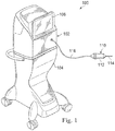
- Fig. 1 illustrates a multi-function vitrectomy surgical apparatus, generally designated by the reference numeral 100, according to an exemplary embodiment.
- the surgical apparatus 100 includes a console 102 that includes a base housing 104 and an associated display screen 106 showing data relating to system operation and performance during a vitrectomy surgical procedure.
- the console 102 may include multiple functions, subassemblies, equipment, and other capabilities for performing one or more surgical treatment procedures, including vitrectomy procedures.
- the surgical apparatus 100 includes a multi-function instrument shown as a vitrectomy probe 110 for performing vitrectomy procedures.
- the vitrectomy probe 110 may be a uni-port hybrid gauge instrument that performs a number of functions, including illumination, infusion, and the vitrectomy treatment for the removal of tissue, such as vitreous humor or removal or irrigation of infusion fluid introduced into a chamber in a patient.
- the vitrectomy probe is a uni-port probe because multiple functions may be performed through a single port.
- the vitrectomy probe 110 includes both a handle portion 112 and a needle portion 114.
- the handle portion 112 attaches to the console 102 via a cable 116 that may be configured to provide irrigation capabilities, aspiration capabilities, power, or other elements or to the vitrectomy probe 110.
- Fig. 2 shows a portion of the needle portion 114 of the vitrectomy probe 110 in greater detail. It is shown as it may be disposed during a surgical procedure protruding into patient tissue, such as an eye 120.
- the eye 120 includes a globe 122 with an anterior chamber 124, a posterior segment 126 and representations of a lens 128, cornea 130, iris 132, ciliary bodies 134, and trabecular meshwork 136.
- the needle portion 114 of the vitrectomy probe 110 extends through surface tissue into the posterior segment 126.
- Fig. 2 also shows a cannula 140 that extends from the exterior of the globe 122 into the posterior segment 126.
- the cannula 140 includes a hub 142 and a main body 144.
- the cannula 140 includes a valve (not shown) disposed therein to limit the egress of fluids, including vitreous, from the posterior segment 126 through the main body 144 and the huh 142.
- the hub 142 is configured to rest on the tissue surface and prevent the cannula 140 from entering further into the posterior segment 126.
- the main body 144 includes an illumination feature that also provides illumination of the surgical region, including die surgical site.
- the illumination features on the cannula 140 may be formed of one or more optical fibers that carry light from a light source and emit the light in the surgical region.
- Some implementations include one or more optical fibers disposed along the main body of the cannula, along the exterior surface, the interior surface, or embedded within the main body in a preformed groove, passage, or other feature.
- the optical fibers may direct light from a light source, such as on the console 102 ( Fig. 1 ), on the hub 142, or elsewhere disposed, and emit the light adjacent the distal end of the main body 144. This may permit the user to visualize the interior of the surgical site using a surgical microscope or other visualization system.
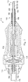
- the needle portion 114 includes a tissue-treating portion, shown here as a cutter portion 150.
- the needle portion also includes an illuminator portion 152 and an infusion portion 154, all of which are coaxially aligned along a central axis 155.
- the needle portion 114 is a hybrid gauge system because it includes an exterior surface having different cross-section widths. For example, in the embodiment shown, the needle portion 114 steps progressively down in diameter or cross-section from the infusion portion 154, to the illuminator portion 152, and to the cutter portion 150.
- the cutter portion 150 preforms the vitrectomy function of opening and closing a port to detach vitreous humor from the retina and to aspirate the vitreous humor from the posterior segment 126.
- the illuminator portion 152 is embedded with illumination elements, such as an optical Fiber, and may provide additional light to the surgical site from a location close in proximity to cutting elements of the cutter portion 150.
- the infusion portion 154 is configured to provide infusion fluid to maintain intraocular pressure during a surgical process. Each of these is described in greater detail below.
- Fig. 3 shows a cross-sectional illustration of the exemplary vitrectomy probe 110.
- the vitrectomy probe 110 is a pneumatically driven probe that operates by receiving pneumatic pressure alternating through first and second air supply ports 160 and 162.
- the needle portion 114 of the vitrectomy probe 110 includes the cutter portion 150 comprising an outer cutting tube 166, an inner cutting tube 168, and a probe actuator shown here as a reciprocating air driven diaphragm 170, all partially encased by the handle portion 112.
- the handle portion 112 includes an end piece 174 at the vitrectomy probe proximal end with the first and second air supply ports 160, 162 and one suction port 176.
- the cutter portion 150 extends from the handle portion and includes a distal end 178.
- Fig. 4A shows the distal end 178 of the cutter portion 150 in greater detail.
- the outer cutting tube 166 has a closed end 182 and an outer port 184 that receives tissue, such as ophthalmic tissue.
- the outer port 184 is in fluid communication with an inner channel 186 of the outer cutting tube 166.
- the inner cutting tube 168 is located within the inner channel 186 of the outer cutting tube 166.
- the inner cutting tube 168 has an inner bore 190, an open end 192, and a cutting surface 194.
- the inner bore 190 is in fluid communication with an aspiration line (not shown) that connects to a vacuum pressure that pulls tissue into the outer port 184 when the inner cutting tube 168 is located away from the outer port 184.
- the inner cutting tube 168 moves within the inner channel 186 of the outer cutting tube 166 to cut tissue that is pulled into the outer port 184 by the aspiration system.
- the ophthalmic tissue received by the outer port 184 is preferably vitreous or membranes.
- the inner cutting tube 168 When used to cut tissue, the inner cutting tube 168 is initially moved away from the outer port 184 and the vacuum pressure pulls tissue into the outer port 184 and the inner channel 186. The inner cutting tube 168 then moves toward the outer port 184 and severs the tissue within the inner channel 186. The severed tissue is pulled through the inner bore 190 of the inner cutting tube 168 by the aspiration system. The inner cutting tube 168 then moves away from the outer port 184, and the cutting process is repeated.
- a cutting cycle includes moving the inner cutting tube 168 to open the outer port 184 and then moving the inner cutting tube 168 to close the outer port 184 to initiate the cut and return the inner cutting tube 168 to its starting position for the next cutting cycle.
- the inner cutting tube 168 is driven by air pressure directed on opposing sides of the diaphragm 170.
- the diaphragm 170 will move distally, displacing the inner cutting tube 168 relative to the outer cutting tube 166, thereby closing the tissue-receiving outer port 184 of the outer cutting tube 166. This cuts any vitreous material which may have been aspirated into the tissue-receiving outer port 184.
- actuator embodiments include a piston motor in place of a diaphragm.
- the cutter portion 150 is arranged so that movement of the piston also moves the inner cutting tube 168 of the cutter portion 150.
- actuator embodiments include other types of pneumatic or electric motors that drive the inner cutting tube 168.
- the cutter portion 150 forms the distal end and has a smaller diameter, and therefore a smaller cross-sectional distance, than the illuminator portion 152 or the infusion portion 154. While the diameter may be any suitable size, in some embodiments, the diameter is selected to be within a range of about 20-40 gauge, and may be selected to be within a range of about 25-30 gauge. In some embodiments, the diameter of the cutter portion 150 is selected to be about 27 gauge.
- the tissue-treating portion may be formed of other instruments or tools configured to treat tissue during a surgical procedure.
- the tissue treating portion is a forceps, a scraper, or other tool that may be used to perform a surgical treatment.
- the illuminator portion 152 is disposed adjacent the cutter portion 150 and is arranged to provide illuminating light to the surgical site so that the user can see the surgical site.
- the illuminator portion emits light in the direction of the cutter portion so that the region being treated by the cutter portion is illuminated.
- the illuminator portion 152 has a larger diameter, and therefore a larger crass-sectional distance, and is coaxial with the cutter portion 150.
- an illumination shoulder 200 provides a step from the cutter portion diameter to the illuminator portion diameter.
- the shoulder 200 may be a smooth increase, such as a tapered shoulder region, or may be a sharp step as shown in Fig. 4A , such that the shoulder surface is perpendicular to the central axis 155 of the needle portion 114.
- the shoulder 200 may be spaced from the surface of the cutter portion 150 so that light emitted from the shoulder 200 may illuminate along the cutter portion 150, as well as away from the cutter portion 150.
- the illuminator portion 152 may comprise one or more optical fibers 202 that are embedded within or disposed along the illuminator portion 152.
- the optical fibers 202 may extend to a light source, such as a light source on the console 102 ( Fig. 1 ).
- the illuminator portion 152 may emit light from a single point or from a plurality of points about the circumference of the illuminator portion.
- two optical fibers 202 are spaced apart from one another by 180 degrees about the central axis 155 of the needle portion 114. In other embodiments, the optical fibers 202 may be spaced at outer angles.
- Some embodiments have three optical fibers disposed 120 degrees apart from one another about the circumference of the illuminator portion 152.
- the optical fibers include an emitting end 204 that is disposed flush with or adjacent to the shoulder 200.
- the multi-gauge nature of the exemplary embodiment in Fig. 4A enables the emitting ends 204 of the optical fibers to be spaced apart from the surface of the cutter portion 150.
- at least one optical fiber 202 has an emitting end that is axially aligned with the outer port 184, in the manner shown in Fig. 4A . Accordingly, light emitted from this optical fiber may enable the user to perceive the vitreous and liquid as it flows toward and into the port during a surgical procedure.
- Some needle portion embodiments include features adjacent the emitting end 204 that permit the light to be emitted at a wide angle, and in some embodiments, in a fan-shape.
- some embodiments include the optical fiber 202 disposed so that the emitting end 204 is disposed proximal of the shoulder 200 and is therefore protected by the surrounding structure.
- the illuminator portion 152 may be formed to provide an illumination pathway that permits the light to illuminate the area about the surgical site.
- the illuminator portion 152 comprises a V-shaped cutout in its outer surface adjacent the shoulder 200.
- the illuminator portion 152 includes an outer cylindrical surface having a flat portion formed at a distal end.
- the emitting end 204 may be disposed between the portion and the outer surface.
- the flat portion may appear as a flat formed on the circumference of the illuminator portion 152 or may be formed as an indented portion or notch (shown as 205 in Fig. 4B ) into the outer surface.
- the indent or notch 205 may have a V-shape with the open end of the V facing toward the distal cutter portion to direct emitted light in a fan-shape toward the cutter portion.
- the illuminator portion 152 has a smaller diameter than the infusion portion 154 and has a larger diameter than the cutter portion 150. While the diameter of the illuminator portion 152 may be any suitable size, in some embodiments, the diameter is selected to be within a range of about 20-40 gauge, and may be selected to be within a range of about 20-28 gauge. In some embodiments, the diameter of the illuminator portion 152 is selected to be about 25 gauge.
- the infusion portion 154 is arranged as an outer surface of the needle portion 114 and is disposed adjacent to the illuminator portion 152.
- the infusion portion 154 acts to direct infusion fluid into the surgical region.
- the infusion portion 154 may form or may include one or more infusion ports 206 that direct infusion fluid into the surgical region.
- the infusion portion 154 and the illuminator portion 152 together form one or more lumens 208 leading to the infusion ports 206.
- the lumen is a single, annular lumen formed between the infusion portion 154 and the illuminator portion 152.
- a plurality of lumens spaced about the illuminator portion 152 is formed into the infusion portion 154.
- one embodiment includes two lumens spaced 180 degrees apart.
- Another embodiment includes three lumens spaced 120 degrees apart.
- the lumens are formed as grooves in the inner surface of the infusion portion 154.
- Fluid provided from the console 102 may be fed to the vitrectomy probe 110 and then to the lumen 208 and out of the infusion port 206.
- the console may include a fluid source such as a reservoir of fluid and a pump or other flow mechanism in fluid communication with such a reservoir.
- the infusion portion 154 has a larger diameter than the illuminator portion 152 and has a larger diameter than the cutter portion 150. It therefore has a larger cross-sectional distance than the illuminator portion 152. While the diameter of the infusion portion 154 may be any suitable size, in some embodiments, the diameter is selected to be within a range of about 15-30 gauge, and may be selected to be within a range of about 18-27 gauge. In some embodiments, the diameter of the infusion portion 154 is selected to be about 23 gauge. While described in terms of diameter, some embodiments have non-circular outer surfaces, and therefore the cross-sectional distance may be used in place of diameter. For example, some instruments may have an oval cross-section or other shape.
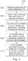
- FIG. 5 illustrates an exemplary method 300 of performing an ophthalmic surgical procedure.
- the method 300 includes a number of enumerated steps. Implementations of the method 300 may include additional steps before, after, and in between the enumerated steps. In some implementations, one or more of the enumerated steps may be omitted or performed in a different order.
- the cannula may be a valve cannula that prevents fluids and/or tissue, such as vitreous humor, from flowing through the cannula port. This helps maintain the intraocular pressure in the eye at an acceptable level.
- the light source on the cannula may be disposed on the console ( Fig. 1 ), on a surgical microscope, or elsewhere about the surgical room. Some embodiments include the source on the cannula itself.
- the method 300 includes inserting a multi-function instrument, such as the vitrectomy probe 110, through the lumen of the cannula and into the interior of the eye.
- a hybrid gauge instrument that includes a tissue-treating portion (e.g., a cutter portion), an illuminator portion, and an infusion portion, with the cutler portion having a first gauge size, the illuminator portion having a second, larger gauge size, and an infusion portion having a third larger gauge size.
- Delivering fluid may include activating an infusion mode on the console or other infusion fluid source, and injecting fluid through the infusion portion of instrument into the interior of the eye.
- injecting fluid through the infusion portion may include injecting fluid from a lumen or port in the infusion portion.
- the lumen or port may be formed within the infusion portion only, or alternatively, may be formed between a surface of the infusion portion and a surface of the illuminator portion.
- the infusion port is annular shaped and coaxial with an axis of the instrument, while in other embodiments, the infusion portion includes one port or a plurality of ports spaced about the axis of the instrument.
- the infusion fluid may be any fluid described herein or that is otherwise suitable for flushing, treating, or maintaining pressure within the eye.
- the instrument may illuminate the interior of the eye with the illuminator portion.
- the illuminator portion may illuminate the surgical site and in some embodiments, may illuminate the tissue-treating portion, such as the cutter portion, of the instrument.
- this technique may include illuminating a port of the cutter portion so that tissue and fluid being aspirated into the port can be visually perceived by the user.
- the illuminator portion may include powering a light source at the console, or may include a light source elsewhere disposed about the surgical room.
- the light source is disposed on the instrument itself. Illuminating the interior of the eye with the light source may include illumination optical fiber tips disposed at or adjacent a shoulder separating a cutter portion from an illuminator portion. The steps 306 and 308 may be performed simultaneously.
- the method may include treating tissue or fluid on the interior of the eye. Treating the tissue may be done in a variety of ways using the instrument. When the tissue-treating portion of the multi-function instrument is a cutter portion, this may include performing a vitrectomy procedure on the eye. It may also include performing other treatments on the eye when the tissue-treating portion of the cutter portion is an alternative tissue or treatment implement.
- the multi-function instrument may be withdrawn. Because the multi-function instrument combines multiple functionality into a single instrument, the instrument may be minimally invasive and multiple functions may be accomplished through only a single incision. This may streamline the surgery, provide for easier instrument handling by the user, and may provide better patient outcome.
- the multi-function instrument may include illumination. infusion, and alternative tool portions for treating tissue.
- some embodiments include forceps as tissue-treatment portions, with hybrid gauge integrated infusion and illumination as described herein.
- Other tissue-treatment portions include scissors, laser probes, aspiration probes, diathermy probes, flex loop probes, fluid injection devices, human lens fragmentation probes, endoscopes, among others. All of these may be used with hybrid gauge integrated infusion and/or illumination as described herein.
- Hand-held fiberoptics may also include hybrid gauge integrated infusion and/or illumination as described herein.
Landscapes
- Health & Medical Sciences (AREA)
- Life Sciences & Earth Sciences (AREA)
- Ophthalmology & Optometry (AREA)
- Surgery (AREA)
- General Health & Medical Sciences (AREA)
- Veterinary Medicine (AREA)
- Public Health (AREA)
- Animal Behavior & Ethology (AREA)
- Heart & Thoracic Surgery (AREA)
- Engineering & Computer Science (AREA)
- Biomedical Technology (AREA)
- Nuclear Medicine, Radiotherapy & Molecular Imaging (AREA)
- Vascular Medicine (AREA)
- Medical Informatics (AREA)
- Molecular Biology (AREA)
- Physics & Mathematics (AREA)
- Biophysics (AREA)
- Radiology & Medical Imaging (AREA)
- Pathology (AREA)
- Optics & Photonics (AREA)
- Surgical Instruments (AREA)
- Infusion, Injection, And Reservoir Apparatuses (AREA)
- Laser Surgery Devices (AREA)
Applications Claiming Priority (2)
| Application Number | Priority Date | Filing Date | Title |
|---|---|---|---|
| US201562266903P | 2015-12-14 | 2015-12-14 | |
| PCT/IB2016/057568 WO2017103778A1 (en) | 2015-12-14 | 2016-12-13 | Uni-port hybrid gauge surgical apparatuses and methods |
Publications (2)
| Publication Number | Publication Date |
|---|---|
| EP3362014A1 EP3362014A1 (en) | 2018-08-22 |
| EP3362014B1 true EP3362014B1 (en) | 2020-02-26 |
Family
ID=57681687
Family Applications (1)
| Application Number | Title | Priority Date | Filing Date |
|---|---|---|---|
| EP16820019.4A Active EP3362014B1 (en) | 2015-12-14 | 2016-12-13 | Uni-port hybrid gauge surgical apparatuses |
Country Status (8)
| Country | Link |
|---|---|
| US (1) | US10376414B2 (enExample) |
| EP (1) | EP3362014B1 (enExample) |
| JP (1) | JP6974322B2 (enExample) |
| CN (1) | CN108366874B (enExample) |
| AU (1) | AU2016372824B2 (enExample) |
| CA (1) | CA3006053C (enExample) |
| ES (1) | ES2778687T3 (enExample) |
| WO (1) | WO2017103778A1 (enExample) |
Families Citing this family (43)
| Publication number | Priority date | Publication date | Assignee | Title |
|---|---|---|---|---|
| WO2014070664A1 (en) | 2012-11-01 | 2014-05-08 | Alcon Research, Ltd. | Illuminated vitrectomy cutter with adjustable illumination aperture |
| ES2873108T3 (es) | 2015-07-13 | 2021-11-03 | Alcon Inc | Cortador del vítreo con sistema de iluminación integrado |
| US10244931B2 (en) | 2015-07-13 | 2019-04-02 | Novartis Ag | Illuminated ophthalmic infusion line and associated devices, systems, and methods |
| US11173008B2 (en) | 2015-11-01 | 2021-11-16 | Alcon Inc. | Illuminated ophthalmic cannula |
| JP6974322B2 (ja) | 2015-12-14 | 2021-12-01 | アルコン インコーポレイティド | 単一ポートハイブリッドゲージ手術装置および方法 |
| CN109496259A (zh) | 2016-08-25 | 2019-03-19 | 诺华股份有限公司 | 用于眼科手术的平面照明器 |
| US11110005B2 (en) | 2016-11-17 | 2021-09-07 | Alcon Inc. | Medical instrument with an integrated optical fiber |
| WO2018092002A1 (en) | 2016-11-17 | 2018-05-24 | Novartis Ag | Medical instrument with an integrated optical fiber |
| WO2018091992A1 (en) | 2016-11-21 | 2018-05-24 | Novartis Ag | Systems and methods using a vitreous visualization tool |
| US10537401B2 (en) * | 2016-11-21 | 2020-01-21 | Novartis Ag | Vitreous visualization system and method |
| US10478266B2 (en) | 2016-12-15 | 2019-11-19 | Novartis Ag | Illuminated surgical probe having multiple optical fibers |
| US20220265469A1 (en) * | 2017-09-08 | 2022-08-25 | Harry Michael Lambert | Ophthalmological surgery microsurgery instruments and methods of use for increasing surgical precision and reducing vitreoretinal instrument insertions and removals and related trauma |
| US20220401261A1 (en) * | 2017-12-07 | 2022-12-22 | Harry Michael Lambert | Ophthalmological surgery microsurgery instruments and methods of use in pars plana vitrectomy for increasing surgical precision and reducing vitreoretinal instrument insertions and removals and related trauma |
| EP3629957B1 (en) | 2017-05-24 | 2021-06-23 | Alcon Inc. | Illuminated infusion cannula |
| WO2018215859A1 (en) | 2017-05-24 | 2018-11-29 | Novartis Ag | Illuminated infusion cannula |
| US11045353B2 (en) | 2017-05-24 | 2021-06-29 | Alcon Inc. | Ophthalmic surgical system with infusion fluid and substance delivery through an infusion cannula |
| US10639197B2 (en) | 2017-06-19 | 2020-05-05 | Alcon Inc. | Vitrectomy probe |
| AU2018313034B2 (en) | 2017-08-09 | 2024-01-18 | Alcon Inc. | Self-illuminating microsurgical cannula device |
| JP2021502848A (ja) | 2017-11-14 | 2021-02-04 | アルコン インコーポレイティド | 照射機能を有するマルチスポットレーザプローブ |
| EP3703601A1 (en) | 2018-01-05 | 2020-09-09 | Alcon Inc. | Multiple illumination transmission through optical fiber |
| WO2019150207A1 (en) * | 2018-02-05 | 2019-08-08 | Novartis Ag | Illuminated cannula |
| US11471242B1 (en) | 2018-03-14 | 2022-10-18 | Alcon Inc. | Medical instruments with an integrated optical fiber and methods of manufacture |
| DE102018108981A1 (de) * | 2018-04-16 | 2019-10-17 | Carl Zeiss Meditec Ag | Ophthalmochirurgische Pinzettenvorrichtung |
| US11986423B1 (en) | 2018-06-18 | 2024-05-21 | Gholam A. Peyman | Method of using a vitrectomy instrument |
| US11020270B1 (en) * | 2018-06-18 | 2021-06-01 | Gholam A. Peyman | Vitrectomy instrument and a system including the same |
| US11395713B2 (en) | 2018-07-19 | 2022-07-26 | Alcon Inc. | Illuminated cannula |
| JP2022530851A (ja) * | 2019-05-01 | 2022-07-04 | スカウトカム リミテッド | 医療用眼科機装置 |
| US20220054313A1 (en) * | 2019-05-03 | 2022-02-24 | Jeffrey Whitsett | New and improved vitrector and method for performing a one-step posterior vitrectomy using the same |
| US11684512B2 (en) | 2019-05-03 | 2023-06-27 | Vista Ophthalmics, Llc | Vitrector and method for performing a one-step posterior vitrectomy using the same |
| CN114630693B (zh) | 2019-10-30 | 2024-10-01 | 爱尔康公司 | 双端口气动连接器 |
| US11819455B1 (en) * | 2020-06-03 | 2023-11-21 | Justin Gutman | Intraocular pressure control device and method for vitreoretinal surgery |
| JP2023534181A (ja) * | 2020-07-23 | 2023-08-08 | アルコン インコーポレイティド | フットスイッチを使用する手術システムの制御 |
| US20230363790A1 (en) * | 2020-09-20 | 2023-11-16 | Microsurgical Technology, Inc. | Goniotomy devices with fluid ingress/egress control |
| WO2022130050A1 (en) * | 2020-12-16 | 2022-06-23 | Alcon Inc. | Ophthalmic surgical microscope with stroboscopic illumination |
| US20220347015A1 (en) * | 2021-05-03 | 2022-11-03 | VisionCare Devices LLC. | Vitrector Cutting Device with Distal Illumination Module |
| KR102631863B1 (ko) * | 2021-05-18 | 2024-01-31 | 주식회사 오큐라이트 | 백내장 수술용 챠퍼 니들 |
| KR102582221B1 (ko) * | 2021-05-18 | 2023-09-25 | 주식회사 오큐라이트 | 백내장 수술용 챠퍼 니들 및 그 제작 방법 그리고 그러한 챠퍼 니들을 포함하는 백내장 수술용 챠퍼 |
| CN117545451A (zh) | 2021-07-20 | 2024-02-09 | 爱尔康公司 | 用于眼科手术的插管 |
| WO2023012531A1 (en) | 2021-08-06 | 2023-02-09 | Alcon Inc. | Vitreoretinal instruments for illumination, fluid aspiration, and photocoagulation |
| US20230118632A1 (en) * | 2021-10-20 | 2023-04-20 | Nova Eye, Inc. | Ophthalmic cannula |
| US12465521B2 (en) | 2022-04-28 | 2025-11-11 | Alcon Inc. | Hybrid 2-port vitrectomy and combined treatment and infusion probe |
| JP7411297B1 (ja) | 2023-08-28 | 2024-01-11 | 株式会社トラベクター | 眼科手術用器具、眼内切除用部材及びその製造方法 |
| US12303703B2 (en) * | 2023-09-07 | 2025-05-20 | Altrix Medical, Inc. | Method of using a medical device |
Family Cites Families (48)
| Publication number | Priority date | Publication date | Assignee | Title |
|---|---|---|---|---|
| JPS517000B1 (enExample) | 1970-01-05 | 1976-03-03 | ||
| US3990453A (en) | 1973-04-25 | 1976-11-09 | Douvas Nicholas G | Apparatus for cataract surgery |
| US4011869A (en) | 1975-08-01 | 1977-03-15 | David Kopf Instruments | Tubular cutting instrument |
| US4168707A (en) | 1977-06-13 | 1979-09-25 | Douvas Nicholas G | Control apparatus for microsurgical instruments |
| US4200106A (en) | 1977-10-11 | 1980-04-29 | Dinkelkamp Henry T | Fixed arc cyclic ophthalmic surgical instrument |
| US5201730A (en) | 1989-10-24 | 1993-04-13 | Surgical Technologies, Inc. | Tissue manipulator for use in vitreous surgery combining a fiber optic endoilluminator with an infusion/aspiration system |
| US5275593A (en) | 1992-04-30 | 1994-01-04 | Surgical Technologies, Inc. | Ophthalmic surgery probe assembly |
| US5683082A (en) * | 1992-08-04 | 1997-11-04 | Kabushiki Kaisha Ace Denken | Gaming system controlling termination of playing and degree of playing difficulty |
| US5478338A (en) | 1993-09-24 | 1995-12-26 | Reynard; Michael | Fiber optic sleeve for surgical instruments |
| US5425730A (en) | 1994-02-16 | 1995-06-20 | Luloh; K. P. | Illumination cannula system for vitreous surgery |
| US5651783A (en) | 1995-12-20 | 1997-07-29 | Reynard; Michael | Fiber optic sleeve for surgical instruments |
| US5716363A (en) | 1996-04-15 | 1998-02-10 | Josephberg; Robert Gary | Pars plana vitrectomy tool |
| AT410055B (de) * | 1999-08-31 | 2003-01-27 | Austrian Laser Produktion Und | Laserskalpell |
| US6887221B1 (en) * | 2001-12-18 | 2005-05-03 | Microsurgical Technology, Inc. | Connector for irrigation-aspiration instrument |
| US6939341B2 (en) | 2002-06-28 | 2005-09-06 | Dutch Opthalmic Research Center (D.O.R.C.) | Surgical cutting tool |
| US7285107B1 (en) * | 2002-10-17 | 2007-10-23 | Alcon, Inc. | Vitreoretinal instrument |
| BRPI0619992A2 (pt) | 2005-12-16 | 2011-10-25 | Alcon Inc | cánula iluminada para infusão |
| US20080172078A1 (en) * | 2007-01-16 | 2008-07-17 | Svetic Ralph E | Reduced traction vitrectomy probe |
| US20080319451A1 (en) * | 2007-06-21 | 2008-12-25 | Jaime Zacharias | Post-occlusion chamber collapse suppressing system for a surgical apparatus and method of use |
| US20090161384A1 (en) | 2007-10-30 | 2009-06-25 | Smith Ronald T | Beveled Tip Surgical Wide-Angle Illuminator |
| US20090163897A1 (en) * | 2007-12-19 | 2009-06-25 | Skinner Allen W | Illuminated Ophthalmic Instruments |
| US9402643B2 (en) | 2008-01-15 | 2016-08-02 | Novartis Ag | Targeted illumination for surgical instrument |
| US8277418B2 (en) | 2009-12-23 | 2012-10-02 | Alcon Research, Ltd. | Ophthalmic valved trocar cannula |
| ES2667486T3 (es) | 2010-05-13 | 2018-05-11 | Doheny Eye Institute | Sistema autónomo con cánula de infusión iluminada |
| WO2012021451A1 (en) | 2010-08-09 | 2012-02-16 | Alcon Research, Ltd. | Illuminated surgical instrument |
| WO2012021628A1 (en) * | 2010-08-13 | 2012-02-16 | Alcon Research, Ltd. | Dual-mode illumination for surgical instrument |
| US20120203075A1 (en) | 2011-02-08 | 2012-08-09 | Christopher Horvath | White coherent laser light launched into nano fibers for surgical illumination |
| TWI561204B (en) * | 2011-05-06 | 2016-12-11 | Alcon Res Ltd | Illuminated microsurgical instrument including optical fiber with beveled end face |
| US8979867B2 (en) | 2011-09-23 | 2015-03-17 | Gholam A. Peyman | Vitreous cutter |
| WO2014070664A1 (en) * | 2012-11-01 | 2014-05-08 | Alcon Research, Ltd. | Illuminated vitrectomy cutter with adjustable illumination aperture |
| US10010447B2 (en) | 2013-12-18 | 2018-07-03 | Novartis Ag | Systems and methods for subretinal delivery of therapeutic agents |
| US10219936B2 (en) * | 2014-09-11 | 2019-03-05 | Orbit Biomedical Limited | Therapeutic agent delivery device with advanceable cannula and needle |
| US10039669B2 (en) | 2014-10-24 | 2018-08-07 | Novartis Ag | Internally illuminated surgical probe |
| US9693898B2 (en) | 2014-11-19 | 2017-07-04 | Novartis Ag | Double-acting vitreous probe with contoured port |
| ES2873108T3 (es) | 2015-07-13 | 2021-11-03 | Alcon Inc | Cortador del vítreo con sistema de iluminación integrado |
| US10244931B2 (en) | 2015-07-13 | 2019-04-02 | Novartis Ag | Illuminated ophthalmic infusion line and associated devices, systems, and methods |
| US11173008B2 (en) | 2015-11-01 | 2021-11-16 | Alcon Inc. | Illuminated ophthalmic cannula |
| JP6974322B2 (ja) | 2015-12-14 | 2021-12-01 | アルコン インコーポレイティド | 単一ポートハイブリッドゲージ手術装置および方法 |
| US10016248B2 (en) | 2015-12-17 | 2018-07-10 | Novartis Ag | Ophthalmic illumination profiles and associated devices, systems, and methods |
| US9956053B2 (en) | 2016-03-04 | 2018-05-01 | Novartis Ag | Cannula with an integrated illumination feature |
| US9839749B2 (en) | 2016-04-27 | 2017-12-12 | Novartis Ag | Intraocular pressure sensing systems, devices, and methods |
| CN109496259A (zh) | 2016-08-25 | 2019-03-19 | 诺华股份有限公司 | 用于眼科手术的平面照明器 |
| WO2018092002A1 (en) | 2016-11-17 | 2018-05-24 | Novartis Ag | Medical instrument with an integrated optical fiber |
| US11110005B2 (en) | 2016-11-17 | 2021-09-07 | Alcon Inc. | Medical instrument with an integrated optical fiber |
| CN110072496A (zh) | 2016-12-15 | 2019-07-30 | 诺华股份有限公司 | 具有可变照明数值孔径的照明式手术探针 |
| US10478266B2 (en) | 2016-12-15 | 2019-11-19 | Novartis Ag | Illuminated surgical probe having multiple optical fibers |
| EP3630025A1 (en) | 2017-05-24 | 2020-04-08 | Alcon Inc. | Ophthalmic endoilluminator |
| WO2018215859A1 (en) | 2017-05-24 | 2018-11-29 | Novartis Ag | Illuminated infusion cannula |
-
2016
- 2016-12-13 JP JP2018530723A patent/JP6974322B2/ja active Active
- 2016-12-13 WO PCT/IB2016/057568 patent/WO2017103778A1/en not_active Ceased
- 2016-12-13 EP EP16820019.4A patent/EP3362014B1/en active Active
- 2016-12-13 CA CA3006053A patent/CA3006053C/en active Active
- 2016-12-13 CN CN201680073243.5A patent/CN108366874B/zh active Active
- 2016-12-13 ES ES16820019T patent/ES2778687T3/es active Active
- 2016-12-13 US US15/376,857 patent/US10376414B2/en active Active
- 2016-12-13 AU AU2016372824A patent/AU2016372824B2/en active Active
Non-Patent Citations (1)
| Title |
|---|
| None * |
Also Published As
| Publication number | Publication date |
|---|---|
| CN108366874B (zh) | 2020-10-30 |
| CA3006053C (en) | 2024-01-23 |
| JP6974322B2 (ja) | 2021-12-01 |
| WO2017103778A1 (en) | 2017-06-22 |
| US10376414B2 (en) | 2019-08-13 |
| CN108366874A (zh) | 2018-08-03 |
| EP3362014A1 (en) | 2018-08-22 |
| AU2016372824A1 (en) | 2018-06-07 |
| US20170165114A1 (en) | 2017-06-15 |
| CA3006053A1 (en) | 2017-06-22 |
| JP2018537214A (ja) | 2018-12-20 |
| AU2016372824B2 (en) | 2021-05-20 |
| ES2778687T3 (es) | 2020-08-11 |
Similar Documents
| Publication | Publication Date | Title |
|---|---|---|
| EP3362014B1 (en) | Uni-port hybrid gauge surgical apparatuses | |
| US11206970B2 (en) | Illuminated ophthalmic infusion line and associated devices, systems, and methods | |
| CN106999297B (zh) | 内照明式外科手术探针 | |
| US9060841B2 (en) | Enhanced flow vitrectomy probe | |
| US20070185514A1 (en) | Microsurgical instrument | |
| US20080172078A1 (en) | Reduced traction vitrectomy probe | |
| US20160166433A1 (en) | Surgical instrument | |
| US20240398621A1 (en) | Surgical apparatus for performing microsurgery including a multifunctional intraocular pick/dissector | |
| US20220401261A1 (en) | Ophthalmological surgery microsurgery instruments and methods of use in pars plana vitrectomy for increasing surgical precision and reducing vitreoretinal instrument insertions and removals and related trauma | |
| US20240415698A1 (en) | Opthalmological microsurgery instrumentation system and methods of use for pars planar vitrectomy | |
| Verma et al. | 39 Vitreoretinal Surgery: Instrumentation | |
| VERMA et al. | Vitreoretinal Surgery |
Legal Events
| Date | Code | Title | Description |
|---|---|---|---|
| STAA | Information on the status of an ep patent application or granted ep patent |
Free format text: STATUS: UNKNOWN |
|
| STAA | Information on the status of an ep patent application or granted ep patent |
Free format text: STATUS: THE INTERNATIONAL PUBLICATION HAS BEEN MADE |
|
| PUAI | Public reference made under article 153(3) epc to a published international application that has entered the european phase |
Free format text: ORIGINAL CODE: 0009012 |
|
| STAA | Information on the status of an ep patent application or granted ep patent |
Free format text: STATUS: REQUEST FOR EXAMINATION WAS MADE |
|
| 17P | Request for examination filed |
Effective date: 20180517 |
|
| AK | Designated contracting states |
Kind code of ref document: A1 Designated state(s): AL AT BE BG CH CY CZ DE DK EE ES FI FR GB GR HR HU IE IS IT LI LT LU LV MC MK MT NL NO PL PT RO RS SE SI SK SM TR |
|
| AX | Request for extension of the european patent |
Extension state: BA ME |
|
| RIN1 | Information on inventor provided before grant (corrected) |
Inventor name: HALLEN, PAUL R. Inventor name: STARK, WALTER J. III |
|
| DAV | Request for validation of the european patent (deleted) | ||
| DAX | Request for extension of the european patent (deleted) | ||
| REG | Reference to a national code |
Ref country code: DE Ref legal event code: R079 Ref document number: 602016030751 Country of ref document: DE Free format text: PREVIOUS MAIN CLASS: A61F0009007000 Ipc: A61B0003000000 |
|
| RIC1 | Information provided on ipc code assigned before grant |
Ipc: A61B 1/313 20060101ALI20190514BHEP Ipc: A61F 9/007 20060101ALI20190514BHEP Ipc: A61B 3/00 20060101AFI20190514BHEP |
|
| GRAP | Despatch of communication of intention to grant a patent |
Free format text: ORIGINAL CODE: EPIDOSNIGR1 |
|
| STAA | Information on the status of an ep patent application or granted ep patent |
Free format text: STATUS: GRANT OF PATENT IS INTENDED |
|
| INTG | Intention to grant announced |
Effective date: 20190624 |
|
| RIN1 | Information on inventor provided before grant (corrected) |
Inventor name: HALLEN, PAUL R. Inventor name: STARK, WALTER J. III |
|
| GRAS | Grant fee paid |
Free format text: ORIGINAL CODE: EPIDOSNIGR3 |
|
| GRAJ | Information related to disapproval of communication of intention to grant by the applicant or resumption of examination proceedings by the epo deleted |
Free format text: ORIGINAL CODE: EPIDOSDIGR1 |
|
| GRAL | Information related to payment of fee for publishing/printing deleted |
Free format text: ORIGINAL CODE: EPIDOSDIGR3 |
|
| STAA | Information on the status of an ep patent application or granted ep patent |
Free format text: STATUS: REQUEST FOR EXAMINATION WAS MADE |
|
| INTC | Intention to grant announced (deleted) | ||
| GRAP | Despatch of communication of intention to grant a patent |
Free format text: ORIGINAL CODE: EPIDOSNIGR1 |
|
| STAA | Information on the status of an ep patent application or granted ep patent |
Free format text: STATUS: GRANT OF PATENT IS INTENDED |
|
| INTG | Intention to grant announced |
Effective date: 20200108 |
|
| GRAA | (expected) grant |
Free format text: ORIGINAL CODE: 0009210 |
|
| STAA | Information on the status of an ep patent application or granted ep patent |
Free format text: STATUS: THE PATENT HAS BEEN GRANTED |
|
| AK | Designated contracting states |
Kind code of ref document: B1 Designated state(s): AL AT BE BG CH CY CZ DE DK EE ES FI FR GB GR HR HU IE IS IT LI LT LU LV MC MK MT NL NO PL PT RO RS SE SI SK SM TR |
|
| RAP1 | Party data changed (applicant data changed or rights of an application transferred) |
Owner name: ALCON INC. |
|
| REG | Reference to a national code |
Ref country code: GB Ref legal event code: FG4D |
|
| REG | Reference to a national code |
Ref country code: CH Ref legal event code: EP |
|
| REG | Reference to a national code |
Ref country code: DE Ref legal event code: R096 Ref document number: 602016030751 Country of ref document: DE |
|
| REG | Reference to a national code |
Ref country code: AT Ref legal event code: REF Ref document number: 1236637 Country of ref document: AT Kind code of ref document: T Effective date: 20200315 |
|
| REG | Reference to a national code |
Ref country code: IE Ref legal event code: FG4D |
|
| PG25 | Lapsed in a contracting state [announced via postgrant information from national office to epo] |
Ref country code: RS Free format text: LAPSE BECAUSE OF FAILURE TO SUBMIT A TRANSLATION OF THE DESCRIPTION OR TO PAY THE FEE WITHIN THE PRESCRIBED TIME-LIMIT Effective date: 20200226 Ref country code: NO Free format text: LAPSE BECAUSE OF FAILURE TO SUBMIT A TRANSLATION OF THE DESCRIPTION OR TO PAY THE FEE WITHIN THE PRESCRIBED TIME-LIMIT Effective date: 20200526 Ref country code: FI Free format text: LAPSE BECAUSE OF FAILURE TO SUBMIT A TRANSLATION OF THE DESCRIPTION OR TO PAY THE FEE WITHIN THE PRESCRIBED TIME-LIMIT Effective date: 20200226 |
|
| REG | Reference to a national code |
Ref country code: NL Ref legal event code: MP Effective date: 20200226 |
|
| REG | Reference to a national code |
Ref country code: ES Ref legal event code: FG2A Ref document number: 2778687 Country of ref document: ES Kind code of ref document: T3 Effective date: 20200811 |
|
| REG | Reference to a national code |
Ref country code: LT Ref legal event code: MG4D |
|
| PG25 | Lapsed in a contracting state [announced via postgrant information from national office to epo] |
Ref country code: BG Free format text: LAPSE BECAUSE OF FAILURE TO SUBMIT A TRANSLATION OF THE DESCRIPTION OR TO PAY THE FEE WITHIN THE PRESCRIBED TIME-LIMIT Effective date: 20200526 Ref country code: IS Free format text: LAPSE BECAUSE OF FAILURE TO SUBMIT A TRANSLATION OF THE DESCRIPTION OR TO PAY THE FEE WITHIN THE PRESCRIBED TIME-LIMIT Effective date: 20200626 Ref country code: GR Free format text: LAPSE BECAUSE OF FAILURE TO SUBMIT A TRANSLATION OF THE DESCRIPTION OR TO PAY THE FEE WITHIN THE PRESCRIBED TIME-LIMIT Effective date: 20200527 Ref country code: SE Free format text: LAPSE BECAUSE OF FAILURE TO SUBMIT A TRANSLATION OF THE DESCRIPTION OR TO PAY THE FEE WITHIN THE PRESCRIBED TIME-LIMIT Effective date: 20200226 Ref country code: LV Free format text: LAPSE BECAUSE OF FAILURE TO SUBMIT A TRANSLATION OF THE DESCRIPTION OR TO PAY THE FEE WITHIN THE PRESCRIBED TIME-LIMIT Effective date: 20200226 Ref country code: HR Free format text: LAPSE BECAUSE OF FAILURE TO SUBMIT A TRANSLATION OF THE DESCRIPTION OR TO PAY THE FEE WITHIN THE PRESCRIBED TIME-LIMIT Effective date: 20200226 |
|
| PG25 | Lapsed in a contracting state [announced via postgrant information from national office to epo] |
Ref country code: NL Free format text: LAPSE BECAUSE OF FAILURE TO SUBMIT A TRANSLATION OF THE DESCRIPTION OR TO PAY THE FEE WITHIN THE PRESCRIBED TIME-LIMIT Effective date: 20200226 |
|
| PG25 | Lapsed in a contracting state [announced via postgrant information from national office to epo] |
Ref country code: SK Free format text: LAPSE BECAUSE OF FAILURE TO SUBMIT A TRANSLATION OF THE DESCRIPTION OR TO PAY THE FEE WITHIN THE PRESCRIBED TIME-LIMIT Effective date: 20200226 Ref country code: SM Free format text: LAPSE BECAUSE OF FAILURE TO SUBMIT A TRANSLATION OF THE DESCRIPTION OR TO PAY THE FEE WITHIN THE PRESCRIBED TIME-LIMIT Effective date: 20200226 Ref country code: EE Free format text: LAPSE BECAUSE OF FAILURE TO SUBMIT A TRANSLATION OF THE DESCRIPTION OR TO PAY THE FEE WITHIN THE PRESCRIBED TIME-LIMIT Effective date: 20200226 Ref country code: PT Free format text: LAPSE BECAUSE OF FAILURE TO SUBMIT A TRANSLATION OF THE DESCRIPTION OR TO PAY THE FEE WITHIN THE PRESCRIBED TIME-LIMIT Effective date: 20200719 Ref country code: LT Free format text: LAPSE BECAUSE OF FAILURE TO SUBMIT A TRANSLATION OF THE DESCRIPTION OR TO PAY THE FEE WITHIN THE PRESCRIBED TIME-LIMIT Effective date: 20200226 Ref country code: DK Free format text: LAPSE BECAUSE OF FAILURE TO SUBMIT A TRANSLATION OF THE DESCRIPTION OR TO PAY THE FEE WITHIN THE PRESCRIBED TIME-LIMIT Effective date: 20200226 Ref country code: RO Free format text: LAPSE BECAUSE OF FAILURE TO SUBMIT A TRANSLATION OF THE DESCRIPTION OR TO PAY THE FEE WITHIN THE PRESCRIBED TIME-LIMIT Effective date: 20200226 Ref country code: CZ Free format text: LAPSE BECAUSE OF FAILURE TO SUBMIT A TRANSLATION OF THE DESCRIPTION OR TO PAY THE FEE WITHIN THE PRESCRIBED TIME-LIMIT Effective date: 20200226 |
|
| REG | Reference to a national code |
Ref country code: AT Ref legal event code: MK05 Ref document number: 1236637 Country of ref document: AT Kind code of ref document: T Effective date: 20200226 |
|
| REG | Reference to a national code |
Ref country code: DE Ref legal event code: R097 Ref document number: 602016030751 Country of ref document: DE |
|
| PLBE | No opposition filed within time limit |
Free format text: ORIGINAL CODE: 0009261 |
|
| STAA | Information on the status of an ep patent application or granted ep patent |
Free format text: STATUS: NO OPPOSITION FILED WITHIN TIME LIMIT |
|
| PG25 | Lapsed in a contracting state [announced via postgrant information from national office to epo] |
Ref country code: AT Free format text: LAPSE BECAUSE OF FAILURE TO SUBMIT A TRANSLATION OF THE DESCRIPTION OR TO PAY THE FEE WITHIN THE PRESCRIBED TIME-LIMIT Effective date: 20200226 |
|
| 26N | No opposition filed |
Effective date: 20201127 |
|
| PG25 | Lapsed in a contracting state [announced via postgrant information from national office to epo] |
Ref country code: PL Free format text: LAPSE BECAUSE OF FAILURE TO SUBMIT A TRANSLATION OF THE DESCRIPTION OR TO PAY THE FEE WITHIN THE PRESCRIBED TIME-LIMIT Effective date: 20200226 Ref country code: SI Free format text: LAPSE BECAUSE OF FAILURE TO SUBMIT A TRANSLATION OF THE DESCRIPTION OR TO PAY THE FEE WITHIN THE PRESCRIBED TIME-LIMIT Effective date: 20200226 |
|
| REG | Reference to a national code |
Ref country code: CH Ref legal event code: PL |
|
| PG25 | Lapsed in a contracting state [announced via postgrant information from national office to epo] |
Ref country code: MC Free format text: LAPSE BECAUSE OF FAILURE TO SUBMIT A TRANSLATION OF THE DESCRIPTION OR TO PAY THE FEE WITHIN THE PRESCRIBED TIME-LIMIT Effective date: 20200226 |
|
| REG | Reference to a national code |
Ref country code: BE Ref legal event code: MM Effective date: 20201231 |
|
| PG25 | Lapsed in a contracting state [announced via postgrant information from national office to epo] |
Ref country code: LU Free format text: LAPSE BECAUSE OF NON-PAYMENT OF DUE FEES Effective date: 20201213 Ref country code: IE Free format text: LAPSE BECAUSE OF NON-PAYMENT OF DUE FEES Effective date: 20201213 |
|
| PG25 | Lapsed in a contracting state [announced via postgrant information from national office to epo] |
Ref country code: CH Free format text: LAPSE BECAUSE OF NON-PAYMENT OF DUE FEES Effective date: 20201231 Ref country code: LI Free format text: LAPSE BECAUSE OF NON-PAYMENT OF DUE FEES Effective date: 20201231 |
|
| PG25 | Lapsed in a contracting state [announced via postgrant information from national office to epo] |
Ref country code: TR Free format text: LAPSE BECAUSE OF FAILURE TO SUBMIT A TRANSLATION OF THE DESCRIPTION OR TO PAY THE FEE WITHIN THE PRESCRIBED TIME-LIMIT Effective date: 20200226 Ref country code: MT Free format text: LAPSE BECAUSE OF FAILURE TO SUBMIT A TRANSLATION OF THE DESCRIPTION OR TO PAY THE FEE WITHIN THE PRESCRIBED TIME-LIMIT Effective date: 20200226 Ref country code: CY Free format text: LAPSE BECAUSE OF FAILURE TO SUBMIT A TRANSLATION OF THE DESCRIPTION OR TO PAY THE FEE WITHIN THE PRESCRIBED TIME-LIMIT Effective date: 20200226 |
|
| PG25 | Lapsed in a contracting state [announced via postgrant information from national office to epo] |
Ref country code: MK Free format text: LAPSE BECAUSE OF FAILURE TO SUBMIT A TRANSLATION OF THE DESCRIPTION OR TO PAY THE FEE WITHIN THE PRESCRIBED TIME-LIMIT Effective date: 20200226 Ref country code: AL Free format text: LAPSE BECAUSE OF FAILURE TO SUBMIT A TRANSLATION OF THE DESCRIPTION OR TO PAY THE FEE WITHIN THE PRESCRIBED TIME-LIMIT Effective date: 20200226 |
|
| PG25 | Lapsed in a contracting state [announced via postgrant information from national office to epo] |
Ref country code: BE Free format text: LAPSE BECAUSE OF NON-PAYMENT OF DUE FEES Effective date: 20201231 |
|
| P01 | Opt-out of the competence of the unified patent court (upc) registered |
Effective date: 20230505 |
|
| PGFP | Annual fee paid to national office [announced via postgrant information from national office to epo] |
Ref country code: DE Payment date: 20241120 Year of fee payment: 9 |
|
| PGFP | Annual fee paid to national office [announced via postgrant information from national office to epo] |
Ref country code: GB Payment date: 20241121 Year of fee payment: 9 |
|
| PGFP | Annual fee paid to national office [announced via postgrant information from national office to epo] |
Ref country code: FR Payment date: 20241121 Year of fee payment: 9 |
|
| PGFP | Annual fee paid to national office [announced via postgrant information from national office to epo] |
Ref country code: IT Payment date: 20241128 Year of fee payment: 9 |
|
| PGFP | Annual fee paid to national office [announced via postgrant information from national office to epo] |
Ref country code: ES Payment date: 20250120 Year of fee payment: 9 |