EP3360740B1 - Module pour un véhicule à deux roues et procédé pour améliorer le comportement au freinage d'un véhicule à deux roues - Google Patents
Module pour un véhicule à deux roues et procédé pour améliorer le comportement au freinage d'un véhicule à deux roues Download PDFInfo
- Publication number
- EP3360740B1 EP3360740B1 EP18154655.7A EP18154655A EP3360740B1 EP 3360740 B1 EP3360740 B1 EP 3360740B1 EP 18154655 A EP18154655 A EP 18154655A EP 3360740 B1 EP3360740 B1 EP 3360740B1
- Authority
- EP
- European Patent Office
- Prior art keywords
- spring
- pressure
- brake
- wheeler
- spring device
- Prior art date
- Legal status (The legal status is an assumption and is not a legal conclusion. Google has not performed a legal analysis and makes no representation as to the accuracy of the status listed.)
- Active
Links
Images


Classifications
-
- B—PERFORMING OPERATIONS; TRANSPORTING
- B60—VEHICLES IN GENERAL
- B60T—VEHICLE BRAKE CONTROL SYSTEMS OR PARTS THEREOF; BRAKE CONTROL SYSTEMS OR PARTS THEREOF, IN GENERAL; ARRANGEMENT OF BRAKING ELEMENTS ON VEHICLES IN GENERAL; PORTABLE DEVICES FOR PREVENTING UNWANTED MOVEMENT OF VEHICLES; VEHICLE MODIFICATIONS TO FACILITATE COOLING OF BRAKES
- B60T8/00—Arrangements for adjusting wheel-braking force to meet varying vehicular or ground-surface conditions, e.g. limiting or varying distribution of braking force
- B60T8/17—Using electrical or electronic regulation means to control braking
- B60T8/1701—Braking or traction control means specially adapted for particular types of vehicles
- B60T8/1706—Braking or traction control means specially adapted for particular types of vehicles for single-track vehicles, e.g. motorcycles
-
- B—PERFORMING OPERATIONS; TRANSPORTING
- B60—VEHICLES IN GENERAL
- B60T—VEHICLE BRAKE CONTROL SYSTEMS OR PARTS THEREOF; BRAKE CONTROL SYSTEMS OR PARTS THEREOF, IN GENERAL; ARRANGEMENT OF BRAKING ELEMENTS ON VEHICLES IN GENERAL; PORTABLE DEVICES FOR PREVENTING UNWANTED MOVEMENT OF VEHICLES; VEHICLE MODIFICATIONS TO FACILITATE COOLING OF BRAKES
- B60T11/00—Transmitting braking action from initiating means to ultimate brake actuator without power assistance or drive or where such assistance or drive is irrelevant
- B60T11/10—Transmitting braking action from initiating means to ultimate brake actuator without power assistance or drive or where such assistance or drive is irrelevant transmitting by fluid means, e.g. hydraulic
- B60T11/16—Master control, e.g. master cylinders
- B60T11/224—Master control, e.g. master cylinders with pressure-varying means, e.g. with two stage operation provided by use of different piston diameters including continuous variation from one diameter to another
-
- B—PERFORMING OPERATIONS; TRANSPORTING
- B60—VEHICLES IN GENERAL
- B60T—VEHICLE BRAKE CONTROL SYSTEMS OR PARTS THEREOF; BRAKE CONTROL SYSTEMS OR PARTS THEREOF, IN GENERAL; ARRANGEMENT OF BRAKING ELEMENTS ON VEHICLES IN GENERAL; PORTABLE DEVICES FOR PREVENTING UNWANTED MOVEMENT OF VEHICLES; VEHICLE MODIFICATIONS TO FACILITATE COOLING OF BRAKES
- B60T13/00—Transmitting braking action from initiating means to ultimate brake actuator with power assistance or drive; Brake systems incorporating such transmitting means, e.g. air-pressure brake systems
- B60T13/10—Transmitting braking action from initiating means to ultimate brake actuator with power assistance or drive; Brake systems incorporating such transmitting means, e.g. air-pressure brake systems with fluid assistance, drive, or release
- B60T13/66—Electrical control in fluid-pressure brake systems
- B60T13/662—Electrical control in fluid-pressure brake systems characterised by specified functions of the control system components
-
- B—PERFORMING OPERATIONS; TRANSPORTING
- B60—VEHICLES IN GENERAL
- B60T—VEHICLE BRAKE CONTROL SYSTEMS OR PARTS THEREOF; BRAKE CONTROL SYSTEMS OR PARTS THEREOF, IN GENERAL; ARRANGEMENT OF BRAKING ELEMENTS ON VEHICLES IN GENERAL; PORTABLE DEVICES FOR PREVENTING UNWANTED MOVEMENT OF VEHICLES; VEHICLE MODIFICATIONS TO FACILITATE COOLING OF BRAKES
- B60T13/00—Transmitting braking action from initiating means to ultimate brake actuator with power assistance or drive; Brake systems incorporating such transmitting means, e.g. air-pressure brake systems
- B60T13/10—Transmitting braking action from initiating means to ultimate brake actuator with power assistance or drive; Brake systems incorporating such transmitting means, e.g. air-pressure brake systems with fluid assistance, drive, or release
- B60T13/66—Electrical control in fluid-pressure brake systems
- B60T13/68—Electrical control in fluid-pressure brake systems by electrically-controlled valves
- B60T13/686—Electrical control in fluid-pressure brake systems by electrically-controlled valves in hydraulic systems or parts thereof
-
- B—PERFORMING OPERATIONS; TRANSPORTING
- B60—VEHICLES IN GENERAL
- B60T—VEHICLE BRAKE CONTROL SYSTEMS OR PARTS THEREOF; BRAKE CONTROL SYSTEMS OR PARTS THEREOF, IN GENERAL; ARRANGEMENT OF BRAKING ELEMENTS ON VEHICLES IN GENERAL; PORTABLE DEVICES FOR PREVENTING UNWANTED MOVEMENT OF VEHICLES; VEHICLE MODIFICATIONS TO FACILITATE COOLING OF BRAKES
- B60T8/00—Arrangements for adjusting wheel-braking force to meet varying vehicular or ground-surface conditions, e.g. limiting or varying distribution of braking force
- B60T8/32—Arrangements for adjusting wheel-braking force to meet varying vehicular or ground-surface conditions, e.g. limiting or varying distribution of braking force responsive to a speed condition, e.g. acceleration or deceleration
- B60T8/321—Arrangements for adjusting wheel-braking force to meet varying vehicular or ground-surface conditions, e.g. limiting or varying distribution of braking force responsive to a speed condition, e.g. acceleration or deceleration deceleration
- B60T8/3225—Systems specially adapted for single-track vehicles, e.g. motorcycles
-
- B—PERFORMING OPERATIONS; TRANSPORTING
- B60—VEHICLES IN GENERAL
- B60T—VEHICLE BRAKE CONTROL SYSTEMS OR PARTS THEREOF; BRAKE CONTROL SYSTEMS OR PARTS THEREOF, IN GENERAL; ARRANGEMENT OF BRAKING ELEMENTS ON VEHICLES IN GENERAL; PORTABLE DEVICES FOR PREVENTING UNWANTED MOVEMENT OF VEHICLES; VEHICLE MODIFICATIONS TO FACILITATE COOLING OF BRAKES
- B60T8/00—Arrangements for adjusting wheel-braking force to meet varying vehicular or ground-surface conditions, e.g. limiting or varying distribution of braking force
- B60T8/32—Arrangements for adjusting wheel-braking force to meet varying vehicular or ground-surface conditions, e.g. limiting or varying distribution of braking force responsive to a speed condition, e.g. acceleration or deceleration
- B60T8/321—Arrangements for adjusting wheel-braking force to meet varying vehicular or ground-surface conditions, e.g. limiting or varying distribution of braking force responsive to a speed condition, e.g. acceleration or deceleration deceleration
- B60T8/328—Systems sharing components with other fluid systems onboard the vehicle
- B60T8/3285—Systems sharing components with other fluid systems onboard the vehicle the other fluid systems being suspension elements
-
- B—PERFORMING OPERATIONS; TRANSPORTING
- B62—LAND VEHICLES FOR TRAVELLING OTHERWISE THAN ON RAILS
- B62J—CYCLE SADDLES OR SEATS; AUXILIARY DEVICES OR ACCESSORIES SPECIALLY ADAPTED TO CYCLES AND NOT OTHERWISE PROVIDED FOR, e.g. ARTICLE CARRIERS OR CYCLE PROTECTORS
- B62J45/00—Electrical equipment arrangements specially adapted for use as accessories on cycles, not otherwise provided for
-
- B—PERFORMING OPERATIONS; TRANSPORTING
- B62—LAND VEHICLES FOR TRAVELLING OTHERWISE THAN ON RAILS
- B62K—CYCLES; CYCLE FRAMES; CYCLE STEERING DEVICES; RIDER-OPERATED TERMINAL CONTROLS SPECIALLY ADAPTED FOR CYCLES; CYCLE AXLE SUSPENSIONS; CYCLE SIDECARS, FORECARS, OR THE LIKE
- B62K25/00—Axle suspensions
- B62K25/04—Axle suspensions for mounting axles resiliently on cycle frame or fork
-
- B—PERFORMING OPERATIONS; TRANSPORTING
- B62—LAND VEHICLES FOR TRAVELLING OTHERWISE THAN ON RAILS
- B62L—BRAKES SPECIALLY ADAPTED FOR CYCLES
- B62L1/00—Brakes; Arrangements thereof
- B62L1/005—Brakes; Arrangements thereof constructional features of brake elements, e.g. fastening of brake blocks in their holders
-
- B—PERFORMING OPERATIONS; TRANSPORTING
- B62—LAND VEHICLES FOR TRAVELLING OTHERWISE THAN ON RAILS
- B62L—BRAKES SPECIALLY ADAPTED FOR CYCLES
- B62L3/00—Brake-actuating mechanisms; Arrangements thereof
- B62L3/02—Brake-actuating mechanisms; Arrangements thereof for control by a hand lever
- B62L3/023—Brake-actuating mechanisms; Arrangements thereof for control by a hand lever acting on fluid pressure systems
-
- B—PERFORMING OPERATIONS; TRANSPORTING
- B60—VEHICLES IN GENERAL
- B60T—VEHICLE BRAKE CONTROL SYSTEMS OR PARTS THEREOF; BRAKE CONTROL SYSTEMS OR PARTS THEREOF, IN GENERAL; ARRANGEMENT OF BRAKING ELEMENTS ON VEHICLES IN GENERAL; PORTABLE DEVICES FOR PREVENTING UNWANTED MOVEMENT OF VEHICLES; VEHICLE MODIFICATIONS TO FACILITATE COOLING OF BRAKES
- B60T2270/00—Further aspects of brake control systems not otherwise provided for
- B60T2270/10—ABS control systems
-
- B—PERFORMING OPERATIONS; TRANSPORTING
- B60—VEHICLES IN GENERAL
- B60T—VEHICLE BRAKE CONTROL SYSTEMS OR PARTS THEREOF; BRAKE CONTROL SYSTEMS OR PARTS THEREOF, IN GENERAL; ARRANGEMENT OF BRAKING ELEMENTS ON VEHICLES IN GENERAL; PORTABLE DEVICES FOR PREVENTING UNWANTED MOVEMENT OF VEHICLES; VEHICLE MODIFICATIONS TO FACILITATE COOLING OF BRAKES
- B60T2270/00—Further aspects of brake control systems not otherwise provided for
- B60T2270/20—ASR control systems
-
- B—PERFORMING OPERATIONS; TRANSPORTING
- B60—VEHICLES IN GENERAL
- B60T—VEHICLE BRAKE CONTROL SYSTEMS OR PARTS THEREOF; BRAKE CONTROL SYSTEMS OR PARTS THEREOF, IN GENERAL; ARRANGEMENT OF BRAKING ELEMENTS ON VEHICLES IN GENERAL; PORTABLE DEVICES FOR PREVENTING UNWANTED MOVEMENT OF VEHICLES; VEHICLE MODIFICATIONS TO FACILITATE COOLING OF BRAKES
- B60T2270/00—Further aspects of brake control systems not otherwise provided for
- B60T2270/89—Criteria for brake release
-
- B—PERFORMING OPERATIONS; TRANSPORTING
- B60—VEHICLES IN GENERAL
- B60T—VEHICLE BRAKE CONTROL SYSTEMS OR PARTS THEREOF; BRAKE CONTROL SYSTEMS OR PARTS THEREOF, IN GENERAL; ARRANGEMENT OF BRAKING ELEMENTS ON VEHICLES IN GENERAL; PORTABLE DEVICES FOR PREVENTING UNWANTED MOVEMENT OF VEHICLES; VEHICLE MODIFICATIONS TO FACILITATE COOLING OF BRAKES
- B60T7/00—Brake-action initiating means
- B60T7/02—Brake-action initiating means for personal initiation
- B60T7/08—Brake-action initiating means for personal initiation hand actuated
-
- B—PERFORMING OPERATIONS; TRANSPORTING
- B60—VEHICLES IN GENERAL
- B60T—VEHICLE BRAKE CONTROL SYSTEMS OR PARTS THEREOF; BRAKE CONTROL SYSTEMS OR PARTS THEREOF, IN GENERAL; ARRANGEMENT OF BRAKING ELEMENTS ON VEHICLES IN GENERAL; PORTABLE DEVICES FOR PREVENTING UNWANTED MOVEMENT OF VEHICLES; VEHICLE MODIFICATIONS TO FACILITATE COOLING OF BRAKES
- B60T8/00—Arrangements for adjusting wheel-braking force to meet varying vehicular or ground-surface conditions, e.g. limiting or varying distribution of braking force
- B60T8/32—Arrangements for adjusting wheel-braking force to meet varying vehicular or ground-surface conditions, e.g. limiting or varying distribution of braking force responsive to a speed condition, e.g. acceleration or deceleration
- B60T8/34—Arrangements for adjusting wheel-braking force to meet varying vehicular or ground-surface conditions, e.g. limiting or varying distribution of braking force responsive to a speed condition, e.g. acceleration or deceleration having a fluid pressure regulator responsive to a speed condition
- B60T8/48—Arrangements for adjusting wheel-braking force to meet varying vehicular or ground-surface conditions, e.g. limiting or varying distribution of braking force responsive to a speed condition, e.g. acceleration or deceleration having a fluid pressure regulator responsive to a speed condition connecting the brake actuator to an alternative or additional source of fluid pressure, e.g. traction control systems
- B60T8/4809—Traction control, stability control, using both the wheel brakes and other automatic braking systems
- B60T8/4827—Traction control, stability control, using both the wheel brakes and other automatic braking systems in hydraulic brake systems
-
- B—PERFORMING OPERATIONS; TRANSPORTING
- B62—LAND VEHICLES FOR TRAVELLING OTHERWISE THAN ON RAILS
- B62M—RIDER PROPULSION OF WHEELED VEHICLES OR SLEDGES; POWERED PROPULSION OF SLEDGES OR SINGLE-TRACK CYCLES; TRANSMISSIONS SPECIALLY ADAPTED FOR SUCH VEHICLES
- B62M6/00—Rider propulsion of wheeled vehicles with additional source of power, e.g. combustion engine or electric motor
- B62M6/40—Rider propelled cycles with auxiliary electric motor
Definitions
- the present invention relates to a two-wheel assembly, in particular an assembly for an electric bicycle and a method for improving a braking behavior of a bicycle, in particular an electric bicycle.
- Modern two-wheelers such as electric bicycles or mountain bikes often have forks and / or middle damping elements on the frame of the two-wheeler to improve ride comfort.
- modern two-wheelers often have hydraulic brake devices that provide improved braking performance than, for example, rim brakes.
- suspension operations wherein the energy generated during the suspension processes is currently not used on the two-wheeler.
- WO 2014/108235 A1 shows a hydraulic anti-lock system for a two-wheeler.
- DE 10 2014 210382 A1 a method for distributing a braking force and a braking device.
- a bicycle is known in which suspension of at least a portion of the bicycle frame can be controlled in response to a brake application.
- the suspension is equipped with a valve which can be closed.
- the two-wheel assembly according to the invention with the features of claim 1 has the advantage over that energy, which is generated by means of a spring device on a bicycle, is also used.
- the two-wheel assembly according to the invention on a spring device and a hydraulic brake device.
- the braking device comprises a wheel brake, a brake release, z. B. a brake lever, and a hydraulic brake line which connects the wheel brake with the brake release.
- the two-wheel assembly comprises a coupling device which couples the spring device and the brake device together.
- the spring device may be a mechanical and / or hydraulic and / or pneumatic spring device.
- the coupling device is arranged such that a spring action of the spring device, i. a compression or a rebound, leads to a pressure change in the hydraulic brake line of the braking device.
- the two-wheel assembly comprises a locking device, which is arranged on the spring device.
- the locking device is arranged to lock the spring device.
- a control unit is particularly preferably configured to activate the spring device as a function of a pressure in the hydraulic brake line. This is particularly helpful if, during a braking operation with the bicycle, a buckling of the handlebar due to a spring effect of the spring device on the front wheel of the bicycle by a shift of the center of gravity of the driver forward occurs.
- the immersion of the fork is caused by a moment when braking due to the increased center of gravity of the system bike / driver (brake nodding) .
- the spring device is locked to the front wheel of the two-wheeler, so that a buckling of the handlebar is prevented and the braking process is safer.
- the coupling device is a unidirectional coupling device, which preferably acts only in the direction of the spring device to the braking device. More preferably, the coupling device also acts in the other direction, for example, for a pressure reduction or to be able to promote the fluid back to the spring device after an engagement can.
- the coupling device is set up such that a spring action of the spring device, ie a compression or a rebound, leads to an increase in pressure in the hydraulic brake line, which can thus be used preferably directly during a braking operation. It can also be a pressure reduction generated by the spring action in the hydraulic brake line.
- a spring action of the spring device ie a compression or a rebound
- the spring device is a fork or strut for a front wheel of a bicycle, in particular a bicycle.
- the spring device is a central spring device on a frame of a bicycle (rear suspension) or a saddle spring device.
- the spring device is a pneumatic spring device, wherein preferably a pressure change in a pneumatic circuit or the like can be transmitted directly to the hydraulic brake line by means of the coupling device.
- the coupling device on a pressure booster Due to the pressure booster can a defined pressure increase or pressure reduction the pressure generated by the spring means for the braking device are made possible.
- the two-wheel assembly comprises a pressure regulator and a control unit.
- the control unit is adapted to regulate the pressure in the hydraulic brake line by means of the pressure regulator.
- the braking device is particularly preferably a front wheel brake of a bicycle, in particular of a bicycle and particularly preferably of an electric bicycle.
- the two-wheel assembly further comprises a pressure accumulator, which is preferably arranged on the hydraulic brake line and whose pressure level is variable by means of the spring means via the coupling device.
- a pressure accumulator which is preferably arranged on the hydraulic brake line and whose pressure level is variable by means of the spring means via the coupling device.
- the pressure accumulator is preferably an overpressure accumulator.
- the pressure from the pressure accumulator can be used directly, for example for generating a braking force in the braking device.
- the pressure accumulator is a vacuum reservoir.
- the vacuum reservoir can be used, for example, to reduce a braking force in the braking device.
- two pressure accumulators are provided, wherein one of the pressure accumulator are provided as an overpressure accumulator and the other of the pressure accumulator as a vacuum accumulator.
- the two-wheel assembly preferably comprises a control device which is adapted to provide by means of the pressure from the pressure accumulator an anti-lock control of a wheel of the two-wheeler.
- the two-wheel assembly comprises a control device which is adapted to provide an anti-skid control by means of the pressure from the pressure accumulator.
- the two-wheel assembly comprises a control unit which is adapted to execute an immobilizer by means of the pressure from the pressure accumulator at a standstill of the two-wheeler.
- a control unit which is adapted to execute an immobilizer by means of the pressure from the pressure accumulator at a standstill of the two-wheeler. This can for example be realized such that at a standstill of the bicycle by means of the pressure in the accumulator, the wheel is activated, so that a wheel of the bicycle is blocked and a pushing away of the bicycle or the like is not possible.
- the present invention relates to a two-wheeler with a two-wheel assembly according to the invention.
- the bicycle is preferably a bicycle.
- the bicycle is more preferably an electric bicycle with an electrical energy storage, in particular a rechargeable battery or a battery, wherein a control unit is connected to the energy store and is supplied by the energy store with electrical energy.
- the present invention relates to a method for using a spring energy, which is generated during a ride with a bicycle, in a braking device of the two-wheeler.
- the method is used for increasing or reducing a braking force of a two-wheeler, wherein a spring force generated during driving is used to increase or reduce a pressure in a hydraulic braking device.
- the method can be carried out in a particularly simple manner if the spring force generated in this case, in particular on a front wheel of the bicycle, is used directly during a braking operation to increase a braking force in the hydraulic braking device. In this way, an immediate coupling between the spring device and the braking device can be made possible, wherein a direct improvement of a braking behavior of the bicycle is achievable.
- the spring device is a pneumatic spring device and an increase in pressure in the pneumatic system is transmitted by means of a pressure booster on the hydraulic brake line.
- a pressure booster on the hydraulic brake line.
- This is also a pressure translation, in particular an increase in pressure, possible.
- the pressure booster can also be used for pressure reduction.
- the pressure transmitted to the hydraulic braking device is stored in a pressure accumulator, in particular on the hydraulic brake line.
- the method according to the invention preferably uses the pressure from the pressure accumulator for anti-skid control and / or anti-skid control.
- the inventive method uses the pressure from the accumulator at a standstill of the two-wheeler for an immobilizer by preferably a wheel brake of the bicycle is blocked.
- the pressure accumulator and the coupling device and the spring device are arranged in a common housing.
- the common housing is particularly preferably a spring strut housing of a suspension fork of a two-wheeler.
- a particularly compact construction of the two-wheel assembly can be provided.
- this also a weight of the two-wheel assembly can be kept small, since in particular components, such as the strut housing, are used, which are already present on the two-wheeler anyway.
- a common control unit is provided for all control tasks. If the bicycle is an electric bicycle, the common control unit is integrated into the existing anyway in the electric bicycle control unit.
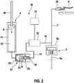
- FIGS. 1 and 2 a two-wheel assembly 50 of a bicycle 1 of a first embodiment described in detail.
- the two-wheeled bicycle 1 is an electric bicycle and comprises a crank mechanism 2 with pedals and an electric drive 3, which is arranged in the region of the crank mechanism 2.
- Reference numeral 11 denotes a battery.
- the two-wheeled vehicle 1 further comprises a front wheel 8 and a rear wheel 9, wherein a spring device 4 is arranged on the front wheel 8.
- the spring device 4 is a suspension fork.
- the spring device 4 comprises a strut 40, which is guided in a spring cylinder 41. Inside the spring cylinder 41, a pneumatic chamber 55 is formed, which is preferably filled with air.
- the strut 40 is connected to a link, not shown, of the bicycle.
- the spring cylinder 41 is connected to a hub of the front wheel 8.
- the two-wheeled vehicle 1 has a brake device with a brake release 6, in this embodiment a brake lever and a brake cylinder 25, a wheel brake 5 and a hydraulic brake line 7.
- the wheel brake 5 comprises a brake disk 5a and a brake caliper 5b.
- FIG. 2 branches off from the hydraulic brake line 7 from a hydraulic connecting line 14, which leads to the spring means 4.
- a coupling device 51 and a pressure regulator 52 is arranged in the hydraulic connection line 14.
- the coupling device 51 is a pressure booster, which has a piston 53 with a first diameter D1 and a second diameter D2, which is smaller than the first diameter D1.
- the piston 53 is directed with the first diameter D1 to the spring device 4 and directed to the second diameter D2 to the hydraulic braking device.
- a return element 54 is provided in the form of a spring to return the piston 53 to its original position.
- the function of the two-wheel assembly 50 is as follows: When the spring device 4 performs a compression process, as in FIG. 2 indicated by the arrow A, gaseous medium, which is arranged in a pneumatic chamber 55, compressed. Since the pneumatic chamber 55 is connected to the piston 53, the piston 53 moves in the direction of arrow B. This results in a pressure increase in the connecting line 14 to the hydraulic braking device. Due to the different diameter on the piston 53, the pressure change from the spring device 4 is translated. A control unit 10 sets a pressure which is regulated by means of the pressure regulator 52, in order to avoid that an inadmissibly high pressure in the hydraulic brake line 7 is generated. The pressure increase in the hydraulic brake line 7 can thus be performed directly to the wheel brake 5 to trigger a braking operation and / or to reinforce.
- the spring device in addition to the described fork on the front wheel for example, a spring means on a frame for suspension of the rear wheel may be or, for example, a spring means on a seat post of the two-wheeler.
- the medium in the spring device 4 of the exemplary embodiment designed as a fork does not have to be gaseous, but may also be liquid.
- the two-wheel assembly is particularly preferably used in an electric bicycle, in which case the control unit 10 is connected to an energy storage 11 of the electric bicycle for power supply.
- the assembly can be attached to a conventional bicycle with additional battery for power supply.
- FIG. 3 shows a bicycle assembly according to a second embodiment of the invention, which substantially corresponds to the first embodiment.
- the two-wheel assembly of the second embodiment further comprises a pressure accumulator 23, which is arranged on the hydraulic connecting line 14 between the pressure regulator 52 and the coupling device 51.
- the pressure accumulator 23 can be connected by means of a first shut-off valve 67 to the connecting line 14 or the connection can be interrupted.
- a second check valve 68 is arranged in the connecting line 14 between the branch point 69 to the pressure accumulator 23 and the pressure regulator 52.
- the two check valves 67, 68 can be opened and closed by means of the control unit 10.
- the second check valve 68 is closed and the first check valve 67 is opened, so that a pressure which is generated by the spring operations during normal driving, are stored in the pressure accumulator 23 as energy can.
- the stored energy in the pressure accumulator 23 can then, for example, in a braking operation by opening the second shut-off valve 68 and the first Block valve 67 are supplied via the connecting line 14 in the hydraulic brake line 7, thereby a braking force on the wheel brake 5 are increased when the pressure accumulator 23 is an excess pressure accumulator.
- the accumulator 23 may also be a vacuum accumulator and may reduce a pressure level in the brake pipe 7, which is useful, for example, in a blocking of the wheel during a braking operation.
- a surge tank can be provided, which allows the pressure build-up and pressure reduction, nachzu specialn fluid in the circuit or to take out of the circulation.
- the expansion tank is preferably connected to the connecting line 14.
- an electrically operated pump is provided to change a pressure level in the hydraulic brake line 7 and / or the pressure accumulator.
- the pump is preferably used in an electric bicycle and supplied with electrical energy by an energy store provided on the electric bicycle.
Landscapes
- Engineering & Computer Science (AREA)
- Mechanical Engineering (AREA)
- Transportation (AREA)
- Physics & Mathematics (AREA)
- Fluid Mechanics (AREA)
- Regulating Braking Force (AREA)
- Springs (AREA)
Claims (15)
- Module pour un véhicule à deux roues, en particulier module de bicyclette, comprenant:- un dispositif amortisseur (4),- un système de freinage hydraulique avec un frein de roue (5), un déclencheur de freinage (6) et une conduite de freinage hydraulique (7), qui relie le déclencheur de freinage (6) au frein de roue (5), et- un système de couplage (51), qui couple l'un à l'autre le dispositif amortisseur (4) et le système de freinage, et- un dispositif de blocage, qui est disposé sur le dispositif amortisseur (4), dans lequel le dispositif de blocage est conçu pour bloquer le dispositif amortisseur (4),caractérisé en ce que le système de couplage (51) est configuré de telle manière qu'une action d'amortissement du dispositif amortisseur (4) conduise à une variation de pression dans la conduite de freinage (7) du système de freinage.
- Module pour un véhicule à deux roues selon la revendication 1, dans lequel le système de couplage (51) est un système de couplage (51) n'agissant que dans une direction.
- Module pour un véhicule à deux roues selon la revendication 2, dans lequel le système de couplage (51) agit à partir du dispositif amortisseur (4) vers le système de freinage.
- Module pour un véhicule à deux roues selon l'une quelconque des revendications précédentes, dans lequel le système de couplage (51) est configuré de telle manière qu'une action d'amortissement du dispositif amortisseur (4) conduise à une augmentation de pression dans la conduite de freinage (7) du système de freinage.
- Module pour un véhicule à deux roues selon l'une quelconque des revendications précédentes, dans lequel le dispositif amortisseur (4) est un amortisseur d'une roue avant (8) ou d'une roue arrière (9) ou d'une selle d'une bicyclette (1).
- Module pour un véhicule à deux roues selon l'une quelconque des revendications précédentes, dans lequel le dispositif amortisseur (4) est un dispositif amortisseur à gaz et le système de couplage (51) couple de façon étanche au fluide le dispositif amortisseur à gaz (4) au système de freinage hydraulique.
- Module pour un véhicule à deux roues selon l'une quelconque des revendications précédentes, dans lequel le système de couplage (51) comprend en outre un convertisseur de pression.
- Module pour un véhicule à deux roues selon l'une quelconque des revendications précédentes, comprenant en outre un régulateur de pression (52) et une unité de commande (10), qui est configurée pour commander une pression dans la conduite de freinage hydraulique (7).
- Module pour un véhicule à deux roues selon l'une quelconque des revendications précédentes, dans lequel le système de freinage est un frein de roue avant d'une bicyclette (1).
- Module pour un véhicule à deux roues selon l'une quelconque des revendications précédentes, comprenant en outre un accumulateur de pression (23), qui est conçu pour stocker de l'énergie, qui est fournie pendant une action d'amortissement du dispositif amortisseur (4), et/ou pour capter de la pression de la conduite de freinage (7), afin de réduire la pression dans la conduite de freinage (7).
- Procédé pour augmenter ou diminuer une force de freinage d'une bicyclette (1), en particulier d'une bicyclette électrique, dans lequel on augmente ou on réduit une force de freinage d'un système de freinage hydraulique par l'action d'amortissement d'un dispositif amortisseur (4), qui est couplé au système de freinage hydraulique, caractérisé par un dispositif de blocage, qui est disposé sur le dispositif amortisseur (4), dans lequel le dispositif de blocage est configuré pour bloquer le dispositif amortisseur (4).
- Procédé selon la revendication 11, dans lequel le dispositif amortisseur (4) est couplé directement au système de freinage, de telle manière qu'une force de freinage produite pendant une opération de freinage soit utilisée directement pour augmenter ou réduire une pression dans le système de freinage hydraulique.
- Procédé selon une revendication 11 ou 12, dans lequel le dispositif amortisseur (4) présente une chambre pneumatique (55) et une variation de pression dans la chambre pneumatique (55) est transmise au système de freinage hydraulique au moyen d'un convertisseur de pression.
- Procédé selon l'une quelconque des revendications 11 à 13, dans lequel la force fournie pour augmenter ou réduire la pression dans la conduite de freinage hydraulique sur la base de l'action d'amortissement du dispositif amortisseur (4) est régulée au moyen d'un régulateur de pression (52).
- Procédé selon l'une quelconque des revendications 11 à 14, dans lequel une force produite au moyen du dispositif amortisseur (4) pendant un déplacement de la bicyclette (1) est stockée dans un accumulateur de pression (10) sous forme d'énergie potentielle et est utilisée en cas de freinage pour augmenter et/ou réduire la force de freinage dans la conduite de freinage hydraulique.
Applications Claiming Priority (1)
| Application Number | Priority Date | Filing Date | Title |
|---|---|---|---|
| DE102017202019.9A DE102017202019A1 (de) | 2017-02-09 | 2017-02-09 | Zweirad-Baugruppe sowie Verfahren zur Verbesserung eines Bremsverhaltens eines Zweirads |
Publications (2)
| Publication Number | Publication Date |
|---|---|
| EP3360740A1 EP3360740A1 (fr) | 2018-08-15 |
| EP3360740B1 true EP3360740B1 (fr) | 2019-11-27 |
Family
ID=61157024
Family Applications (1)
| Application Number | Title | Priority Date | Filing Date |
|---|---|---|---|
| EP18154655.7A Active EP3360740B1 (fr) | 2017-02-09 | 2018-02-01 | Module pour un véhicule à deux roues et procédé pour améliorer le comportement au freinage d'un véhicule à deux roues |
Country Status (2)
| Country | Link |
|---|---|
| EP (1) | EP3360740B1 (fr) |
| DE (1) | DE102017202019A1 (fr) |
Families Citing this family (3)
| Publication number | Priority date | Publication date | Assignee | Title |
|---|---|---|---|---|
| DE102019117929A1 (de) * | 2019-07-03 | 2021-01-07 | Gustav Magenwirth Gmbh & Co. Kg | Bremssystem mit Feststellbremsvorrichtung |
| CN112722138A (zh) * | 2021-02-03 | 2021-04-30 | 浙江欧凯车业有限公司 | 电动车 |
| DE102023210963A1 (de) * | 2023-11-06 | 2024-12-12 | Zf Friedrichshafen Ag | Fahrwerksystem für ein Fahrrad |
Family Cites Families (7)
| Publication number | Priority date | Publication date | Assignee | Title |
|---|---|---|---|---|
| US6106078A (en) * | 1998-06-26 | 2000-08-22 | General Motors Corporation | Pressure augmentation for brake apply system |
| US7552935B2 (en) * | 2005-09-26 | 2009-06-30 | Specialized Bicycle Components, Inc. | Integrated bicycle shifting and suspension system |
| DE102007054771A1 (de) * | 2007-11-16 | 2009-05-20 | Uwe Schulte-Michels | Elektromechanischer Stoßdämpfer bzw. elektromechanisches Feder-Dämpfer Element (zur Umwandlung kinetischer Energie in elektrische Energie bei jeder Art von Fahrzeugen und Schwingungskörpern) |
| DE102007056700B4 (de) * | 2007-11-24 | 2012-03-29 | Grammer Aktiengesellschaft | Vorrichtung mit einem Federungssystem sowie Verfahren zur Einstellung eines Federungssystems |
| DE102013200422A1 (de) * | 2013-01-14 | 2014-07-17 | Robert Bosch Gmbh | Hydraulisches Antiblockiersystem für ein Zweirad |
| DE102013217754A1 (de) * | 2013-09-05 | 2015-03-05 | Robert Bosch Gmbh | Wegfahrsperre für ein fahrrad und fahrrad |
| DE102014210382A1 (de) * | 2014-06-03 | 2015-12-03 | Robert Bosch Gmbh | Verfahren zur Verteilung einer Bremskraft und Bremseinrichtung |
-
2017
- 2017-02-09 DE DE102017202019.9A patent/DE102017202019A1/de not_active Withdrawn
-
2018
- 2018-02-01 EP EP18154655.7A patent/EP3360740B1/fr active Active
Non-Patent Citations (1)
| Title |
|---|
| None * |
Also Published As
| Publication number | Publication date |
|---|---|
| EP3360740A1 (fr) | 2018-08-15 |
| DE102017202019A1 (de) | 2018-08-09 |
Similar Documents
| Publication | Publication Date | Title |
|---|---|---|
| DE102008019469B4 (de) | Überschlagschutzsystem für Zweiräder | |
| EP3360740B1 (fr) | Module pour un véhicule à deux roues et procédé pour améliorer le comportement au freinage d'un véhicule à deux roues | |
| WO1999038718A1 (fr) | Procede et dispositif de fonctionnement d'un vehicule a moteur | |
| WO2012028700A1 (fr) | Procédé permettant de faire fonctionner un système de freinage, systèmes de freinage mettant en œuvre ledit procédé et véhicule automobile muni d'un des systèmes de freinage de ce type | |
| DE102012209223A1 (de) | Bremssystem für ein Motorrad, Verfahren zum Montieren eines Bremssystems an einem Motorrad und Verfahren zum Abbremsen eines Motorrads | |
| DE102012222974A1 (de) | Verfahren zum Betreiben eines Bremssystems eines Fahrzeugs und Steuervorrichtung für ein Bremssystem eines Fahrzeugs | |
| DE3133576A1 (de) | Bremsnickausgleich fuer teleskopgabeln bei einspur-fahrzeugen | |
| DE102013209353A1 (de) | Verfahren zum Einstellen einer hydraulischen Fahrzeugbremse | |
| DE102014201792A1 (de) | Aktuatorvorrichtung für eine hydraulische Bremse eines Fahrzeugs, Fahrzeug sowie Verfahren zum Aktuieren einer hydraulischen Bremse eines Fahrzeugs | |
| EP3360739B1 (fr) | Module pour un véhicule à deux roues avec un accumulateur de pression et procédé de stockage de l'énergie fourni par la suspension de véhicule | |
| EP4565462A1 (fr) | Système de freinage hydraulique de véhicule à deux roues | |
| DE3510910A1 (de) | Verfahren zum betreiben einer fahrzeugbremsanlage und fahrzeugbremsanlage | |
| DE102010008018A1 (de) | Kraftfahrzeug mit einem Hybridantrieb | |
| DE202017001934U1 (de) | Hydraulische Schaltung für Fahrradbremse | |
| EP4297998A1 (fr) | Procédé de freinage d'un véhicule et système de freinage | |
| DE2743204A1 (de) | Bremskraftregler fuer ein hydraulisches motorrad-bremssystem | |
| CN211335945U (zh) | 一种断油压的驻车制动机构 | |
| DE102012209521A1 (de) | Simulatorvorrichtung für ein Bremssystem eines Motorrads, Verfahren zum Montieren eines Bremssystems an einem Motorrad und Verfahren zum Abbremsen eines Motorrads | |
| DE102009048785A1 (de) | Kraftfahrzeug mit einem Hydridantrieb | |
| DE102017202021A1 (de) | Zweirad-Baugruppe, insbesondere Fahrrad-Baugruppe mit verbesserter Sicherheit | |
| DE102009055366A1 (de) | Hydraulisches Bremssystem für ein Fahrrad | |
| DE102018216563A1 (de) | Bremseinrichtung mit aktiver Bremskrafteinstellung | |
| DE102015012016A1 (de) | Bremsanlage und Verfahren zum Bremsen eines Zweirades | |
| DE202017001933U1 (de) | Hydraulische Schaltung für Fahrradbremse | |
| DE102022103226A1 (de) | Hydraulische Hinterradbremse für ein lenkergeführtes Fahrzeug sowie Fahrzeug mit der Hinterradbremse |
Legal Events
| Date | Code | Title | Description |
|---|---|---|---|
| PUAI | Public reference made under article 153(3) epc to a published international application that has entered the european phase |
Free format text: ORIGINAL CODE: 0009012 |
|
| STAA | Information on the status of an ep patent application or granted ep patent |
Free format text: STATUS: THE APPLICATION HAS BEEN PUBLISHED |
|
| AK | Designated contracting states |
Kind code of ref document: A1 Designated state(s): AL AT BE BG CH CY CZ DE DK EE ES FI FR GB GR HR HU IE IS IT LI LT LU LV MC MK MT NL NO PL PT RO RS SE SI SK SM TR |
|
| AX | Request for extension of the european patent |
Extension state: BA ME |
|
| STAA | Information on the status of an ep patent application or granted ep patent |
Free format text: STATUS: REQUEST FOR EXAMINATION WAS MADE |
|
| 17P | Request for examination filed |
Effective date: 20190215 |
|
| RBV | Designated contracting states (corrected) |
Designated state(s): AL AT BE BG CH CY CZ DE DK EE ES FI FR GB GR HR HU IE IS IT LI LT LU LV MC MK MT NL NO PL PT RO RS SE SI SK SM TR |
|
| STAA | Information on the status of an ep patent application or granted ep patent |
Free format text: STATUS: EXAMINATION IS IN PROGRESS |
|
| REG | Reference to a national code |
Ref country code: DE Ref legal event code: R079 Ref document number: 502018000409 Country of ref document: DE Free format text: PREVIOUS MAIN CLASS: B60T0008320000 Ipc: B60T0008170000 |
|
| 17Q | First examination report despatched |
Effective date: 20190503 |
|
| GRAP | Despatch of communication of intention to grant a patent |
Free format text: ORIGINAL CODE: EPIDOSNIGR1 |
|
| STAA | Information on the status of an ep patent application or granted ep patent |
Free format text: STATUS: GRANT OF PATENT IS INTENDED |
|
| RIC1 | Information provided on ipc code assigned before grant |
Ipc: B62J 99/00 20090101ALN20190527BHEP Ipc: B60T 7/08 20060101ALN20190527BHEP Ipc: B62K 25/04 20060101ALI20190527BHEP Ipc: B62M 6/40 20100101ALN20190527BHEP Ipc: B60T 8/32 20060101ALI20190527BHEP Ipc: B62L 3/02 20060101ALI20190527BHEP Ipc: B60T 8/17 20060101AFI20190527BHEP Ipc: B62L 1/00 20060101ALI20190527BHEP Ipc: B60T 8/48 20060101ALN20190527BHEP Ipc: B60T 13/66 20060101ALI20190527BHEP Ipc: B60T 11/224 20060101ALI20190527BHEP Ipc: B60T 13/68 20060101ALI20190527BHEP |
|
| INTG | Intention to grant announced |
Effective date: 20190701 |
|
| GRAS | Grant fee paid |
Free format text: ORIGINAL CODE: EPIDOSNIGR3 |
|
| GRAA | (expected) grant |
Free format text: ORIGINAL CODE: 0009210 |
|
| STAA | Information on the status of an ep patent application or granted ep patent |
Free format text: STATUS: THE PATENT HAS BEEN GRANTED |
|
| AK | Designated contracting states |
Kind code of ref document: B1 Designated state(s): AL AT BE BG CH CY CZ DE DK EE ES FI FR GB GR HR HU IE IS IT LI LT LU LV MC MK MT NL NO PL PT RO RS SE SI SK SM TR |
|
| REG | Reference to a national code |
Ref country code: GB Ref legal event code: FG4D Free format text: NOT ENGLISH |
|
| REG | Reference to a national code |
Ref country code: CH Ref legal event code: EP |
|
| REG | Reference to a national code |
Ref country code: AT Ref legal event code: REF Ref document number: 1206318 Country of ref document: AT Kind code of ref document: T Effective date: 20191215 |
|
| REG | Reference to a national code |
Ref country code: DE Ref legal event code: R096 Ref document number: 502018000409 Country of ref document: DE |
|
| REG | Reference to a national code |
Ref country code: IE Ref legal event code: FG4D Free format text: LANGUAGE OF EP DOCUMENT: GERMAN |
|
| REG | Reference to a national code |
Ref country code: LT Ref legal event code: MG4D |
|
| RAP2 | Party data changed (patent owner data changed or rights of a patent transferred) |
Owner name: ROBERT BOSCH GMBH |
|
| PG25 | Lapsed in a contracting state [announced via postgrant information from national office to epo] |
Ref country code: FI Free format text: LAPSE BECAUSE OF FAILURE TO SUBMIT A TRANSLATION OF THE DESCRIPTION OR TO PAY THE FEE WITHIN THE PRESCRIBED TIME-LIMIT Effective date: 20191127 Ref country code: BG Free format text: LAPSE BECAUSE OF FAILURE TO SUBMIT A TRANSLATION OF THE DESCRIPTION OR TO PAY THE FEE WITHIN THE PRESCRIBED TIME-LIMIT Effective date: 20200227 Ref country code: NO Free format text: LAPSE BECAUSE OF FAILURE TO SUBMIT A TRANSLATION OF THE DESCRIPTION OR TO PAY THE FEE WITHIN THE PRESCRIBED TIME-LIMIT Effective date: 20200227 Ref country code: GR Free format text: LAPSE BECAUSE OF FAILURE TO SUBMIT A TRANSLATION OF THE DESCRIPTION OR TO PAY THE FEE WITHIN THE PRESCRIBED TIME-LIMIT Effective date: 20200228 Ref country code: LT Free format text: LAPSE BECAUSE OF FAILURE TO SUBMIT A TRANSLATION OF THE DESCRIPTION OR TO PAY THE FEE WITHIN THE PRESCRIBED TIME-LIMIT Effective date: 20191127 Ref country code: LV Free format text: LAPSE BECAUSE OF FAILURE TO SUBMIT A TRANSLATION OF THE DESCRIPTION OR TO PAY THE FEE WITHIN THE PRESCRIBED TIME-LIMIT Effective date: 20191127 Ref country code: SE Free format text: LAPSE BECAUSE OF FAILURE TO SUBMIT A TRANSLATION OF THE DESCRIPTION OR TO PAY THE FEE WITHIN THE PRESCRIBED TIME-LIMIT Effective date: 20191127 |
|
| REG | Reference to a national code |
Ref country code: NL Ref legal event code: FP |
|
| PG25 | Lapsed in a contracting state [announced via postgrant information from national office to epo] |
Ref country code: IS Free format text: LAPSE BECAUSE OF FAILURE TO SUBMIT A TRANSLATION OF THE DESCRIPTION OR TO PAY THE FEE WITHIN THE PRESCRIBED TIME-LIMIT Effective date: 20200327 Ref country code: RS Free format text: LAPSE BECAUSE OF FAILURE TO SUBMIT A TRANSLATION OF THE DESCRIPTION OR TO PAY THE FEE WITHIN THE PRESCRIBED TIME-LIMIT Effective date: 20191127 Ref country code: HR Free format text: LAPSE BECAUSE OF FAILURE TO SUBMIT A TRANSLATION OF THE DESCRIPTION OR TO PAY THE FEE WITHIN THE PRESCRIBED TIME-LIMIT Effective date: 20191127 |
|
| PG25 | Lapsed in a contracting state [announced via postgrant information from national office to epo] |
Ref country code: AL Free format text: LAPSE BECAUSE OF FAILURE TO SUBMIT A TRANSLATION OF THE DESCRIPTION OR TO PAY THE FEE WITHIN THE PRESCRIBED TIME-LIMIT Effective date: 20191127 |
|
| PG25 | Lapsed in a contracting state [announced via postgrant information from national office to epo] |
Ref country code: ES Free format text: LAPSE BECAUSE OF FAILURE TO SUBMIT A TRANSLATION OF THE DESCRIPTION OR TO PAY THE FEE WITHIN THE PRESCRIBED TIME-LIMIT Effective date: 20191127 Ref country code: DK Free format text: LAPSE BECAUSE OF FAILURE TO SUBMIT A TRANSLATION OF THE DESCRIPTION OR TO PAY THE FEE WITHIN THE PRESCRIBED TIME-LIMIT Effective date: 20191127 Ref country code: RO Free format text: LAPSE BECAUSE OF FAILURE TO SUBMIT A TRANSLATION OF THE DESCRIPTION OR TO PAY THE FEE WITHIN THE PRESCRIBED TIME-LIMIT Effective date: 20191127 Ref country code: CZ Free format text: LAPSE BECAUSE OF FAILURE TO SUBMIT A TRANSLATION OF THE DESCRIPTION OR TO PAY THE FEE WITHIN THE PRESCRIBED TIME-LIMIT Effective date: 20191127 Ref country code: PT Free format text: LAPSE BECAUSE OF FAILURE TO SUBMIT A TRANSLATION OF THE DESCRIPTION OR TO PAY THE FEE WITHIN THE PRESCRIBED TIME-LIMIT Effective date: 20200419 Ref country code: EE Free format text: LAPSE BECAUSE OF FAILURE TO SUBMIT A TRANSLATION OF THE DESCRIPTION OR TO PAY THE FEE WITHIN THE PRESCRIBED TIME-LIMIT Effective date: 20191127 |
|
| REG | Reference to a national code |
Ref country code: DE Ref legal event code: R097 Ref document number: 502018000409 Country of ref document: DE |
|
| PG25 | Lapsed in a contracting state [announced via postgrant information from national office to epo] |
Ref country code: SK Free format text: LAPSE BECAUSE OF FAILURE TO SUBMIT A TRANSLATION OF THE DESCRIPTION OR TO PAY THE FEE WITHIN THE PRESCRIBED TIME-LIMIT Effective date: 20191127 Ref country code: SM Free format text: LAPSE BECAUSE OF FAILURE TO SUBMIT A TRANSLATION OF THE DESCRIPTION OR TO PAY THE FEE WITHIN THE PRESCRIBED TIME-LIMIT Effective date: 20191127 |
|
| PLBE | No opposition filed within time limit |
Free format text: ORIGINAL CODE: 0009261 |
|
| STAA | Information on the status of an ep patent application or granted ep patent |
Free format text: STATUS: NO OPPOSITION FILED WITHIN TIME LIMIT |
|
| REG | Reference to a national code |
Ref country code: BE Ref legal event code: MM Effective date: 20200229 |
|
| PG25 | Lapsed in a contracting state [announced via postgrant information from national office to epo] |
Ref country code: MC Free format text: LAPSE BECAUSE OF FAILURE TO SUBMIT A TRANSLATION OF THE DESCRIPTION OR TO PAY THE FEE WITHIN THE PRESCRIBED TIME-LIMIT Effective date: 20191127 Ref country code: LU Free format text: LAPSE BECAUSE OF NON-PAYMENT OF DUE FEES Effective date: 20200201 |
|
| 26N | No opposition filed |
Effective date: 20200828 |
|
| PG25 | Lapsed in a contracting state [announced via postgrant information from national office to epo] |
Ref country code: PL Free format text: LAPSE BECAUSE OF FAILURE TO SUBMIT A TRANSLATION OF THE DESCRIPTION OR TO PAY THE FEE WITHIN THE PRESCRIBED TIME-LIMIT Effective date: 20191127 Ref country code: SI Free format text: LAPSE BECAUSE OF FAILURE TO SUBMIT A TRANSLATION OF THE DESCRIPTION OR TO PAY THE FEE WITHIN THE PRESCRIBED TIME-LIMIT Effective date: 20191127 |
|
| PG25 | Lapsed in a contracting state [announced via postgrant information from national office to epo] |
Ref country code: FR Free format text: LAPSE BECAUSE OF NON-PAYMENT OF DUE FEES Effective date: 20200229 Ref country code: IT Free format text: LAPSE BECAUSE OF FAILURE TO SUBMIT A TRANSLATION OF THE DESCRIPTION OR TO PAY THE FEE WITHIN THE PRESCRIBED TIME-LIMIT Effective date: 20191127 Ref country code: IE Free format text: LAPSE BECAUSE OF NON-PAYMENT OF DUE FEES Effective date: 20200201 |
|
| PG25 | Lapsed in a contracting state [announced via postgrant information from national office to epo] |
Ref country code: BE Free format text: LAPSE BECAUSE OF NON-PAYMENT OF DUE FEES Effective date: 20200229 |
|
| PGFP | Annual fee paid to national office [announced via postgrant information from national office to epo] |
Ref country code: NL Payment date: 20210218 Year of fee payment: 4 |
|
| PG25 | Lapsed in a contracting state [announced via postgrant information from national office to epo] |
Ref country code: CH Free format text: LAPSE BECAUSE OF NON-PAYMENT OF DUE FEES Effective date: 20210228 Ref country code: LI Free format text: LAPSE BECAUSE OF NON-PAYMENT OF DUE FEES Effective date: 20210228 |
|
| PG25 | Lapsed in a contracting state [announced via postgrant information from national office to epo] |
Ref country code: TR Free format text: LAPSE BECAUSE OF FAILURE TO SUBMIT A TRANSLATION OF THE DESCRIPTION OR TO PAY THE FEE WITHIN THE PRESCRIBED TIME-LIMIT Effective date: 20191127 Ref country code: MT Free format text: LAPSE BECAUSE OF FAILURE TO SUBMIT A TRANSLATION OF THE DESCRIPTION OR TO PAY THE FEE WITHIN THE PRESCRIBED TIME-LIMIT Effective date: 20191127 Ref country code: CY Free format text: LAPSE BECAUSE OF FAILURE TO SUBMIT A TRANSLATION OF THE DESCRIPTION OR TO PAY THE FEE WITHIN THE PRESCRIBED TIME-LIMIT Effective date: 20191127 |
|
| PG25 | Lapsed in a contracting state [announced via postgrant information from national office to epo] |
Ref country code: MK Free format text: LAPSE BECAUSE OF FAILURE TO SUBMIT A TRANSLATION OF THE DESCRIPTION OR TO PAY THE FEE WITHIN THE PRESCRIBED TIME-LIMIT Effective date: 20191127 |
|
| REG | Reference to a national code |
Ref country code: NL Ref legal event code: MM Effective date: 20220301 |
|
| GBPC | Gb: european patent ceased through non-payment of renewal fee |
Effective date: 20220201 |
|
| PG25 | Lapsed in a contracting state [announced via postgrant information from national office to epo] |
Ref country code: NL Free format text: LAPSE BECAUSE OF NON-PAYMENT OF DUE FEES Effective date: 20220301 |
|
| PG25 | Lapsed in a contracting state [announced via postgrant information from national office to epo] |
Ref country code: GB Free format text: LAPSE BECAUSE OF NON-PAYMENT OF DUE FEES Effective date: 20220201 |
|
| PGFP | Annual fee paid to national office [announced via postgrant information from national office to epo] |
Ref country code: DE Payment date: 20230426 Year of fee payment: 6 |
|
| REG | Reference to a national code |
Ref country code: AT Ref legal event code: MM01 Ref document number: 1206318 Country of ref document: AT Kind code of ref document: T Effective date: 20230201 |
|
| PG25 | Lapsed in a contracting state [announced via postgrant information from national office to epo] |
Ref country code: AT Free format text: LAPSE BECAUSE OF NON-PAYMENT OF DUE FEES Effective date: 20230201 |
|
| PG25 | Lapsed in a contracting state [announced via postgrant information from national office to epo] |
Ref country code: AT Free format text: LAPSE BECAUSE OF NON-PAYMENT OF DUE FEES Effective date: 20230201 |
|
| REG | Reference to a national code |
Ref country code: DE Ref legal event code: R119 Ref document number: 502018000409 Country of ref document: DE |
|
| PG25 | Lapsed in a contracting state [announced via postgrant information from national office to epo] |
Ref country code: DE Free format text: LAPSE BECAUSE OF NON-PAYMENT OF DUE FEES Effective date: 20240903 |
|
| PG25 | Lapsed in a contracting state [announced via postgrant information from national office to epo] |
Ref country code: DE Free format text: LAPSE BECAUSE OF NON-PAYMENT OF DUE FEES Effective date: 20240903 |
|
| PGFP | Annual fee paid to national office [announced via postgrant information from national office to epo] |
Ref country code: AT Payment date: 20260410 Year of fee payment: 5 |