EP3360498B1 - Adapters and systems incorporating the same for providing an electrosurgical forceps with clip-applying functionality - Google Patents
Adapters and systems incorporating the same for providing an electrosurgical forceps with clip-applying functionality Download PDFInfo
- Publication number
- EP3360498B1 EP3360498B1 EP18155801.6A EP18155801A EP3360498B1 EP 3360498 B1 EP3360498 B1 EP 3360498B1 EP 18155801 A EP18155801 A EP 18155801A EP 3360498 B1 EP3360498 B1 EP 3360498B1
- Authority
- EP
- European Patent Office
- Prior art keywords
- adapter
- surgical
- jaw
- surgical clip
- clip
- Prior art date
- Legal status (The legal status is an assumption and is not a legal conclusion. Google has not performed a legal analysis and makes no representation as to the accuracy of the status listed.)
- Active
Links
Images


Classifications
-
- A—HUMAN NECESSITIES
- A61—MEDICAL OR VETERINARY SCIENCE; HYGIENE
- A61B—DIAGNOSIS; SURGERY; IDENTIFICATION
- A61B18/00—Surgical instruments, devices or methods for transferring non-mechanical forms of energy to or from the body
- A61B18/04—Surgical instruments, devices or methods for transferring non-mechanical forms of energy to or from the body by heating
- A61B18/12—Surgical instruments, devices or methods for transferring non-mechanical forms of energy to or from the body by heating by passing a current through the tissue to be heated, e.g. high-frequency current
- A61B18/14—Probes or electrodes therefor
- A61B18/1442—Probes having pivoting end effectors, e.g. forceps
- A61B18/1445—Probes having pivoting end effectors, e.g. forceps at the distal end of a shaft, e.g. forceps or scissors at the end of a rigid rod
-
- A—HUMAN NECESSITIES
- A61—MEDICAL OR VETERINARY SCIENCE; HYGIENE
- A61B—DIAGNOSIS; SURGERY; IDENTIFICATION
- A61B18/00—Surgical instruments, devices or methods for transferring non-mechanical forms of energy to or from the body
- A61B18/04—Surgical instruments, devices or methods for transferring non-mechanical forms of energy to or from the body by heating
- A61B18/08—Surgical instruments, devices or methods for transferring non-mechanical forms of energy to or from the body by heating by means of electrically-heated probes
- A61B18/082—Probes or electrodes therefor
- A61B18/085—Forceps, scissors
-
- A—HUMAN NECESSITIES
- A61—MEDICAL OR VETERINARY SCIENCE; HYGIENE
- A61B—DIAGNOSIS; SURGERY; IDENTIFICATION
- A61B17/00—Surgical instruments, devices or methods, e.g. tourniquets
- A61B17/12—Surgical instruments, devices or methods, e.g. tourniquets for ligaturing or otherwise compressing tubular parts of the body, e.g. blood vessels, umbilical cord
- A61B17/122—Clamps or clips, e.g. for the umbilical cord
-
- A—HUMAN NECESSITIES
- A61—MEDICAL OR VETERINARY SCIENCE; HYGIENE
- A61B—DIAGNOSIS; SURGERY; IDENTIFICATION
- A61B17/00—Surgical instruments, devices or methods, e.g. tourniquets
- A61B17/12—Surgical instruments, devices or methods, e.g. tourniquets for ligaturing or otherwise compressing tubular parts of the body, e.g. blood vessels, umbilical cord
- A61B17/128—Surgical instruments, devices or methods, e.g. tourniquets for ligaturing or otherwise compressing tubular parts of the body, e.g. blood vessels, umbilical cord for applying or removing clamps or clips
- A61B17/1285—Surgical instruments, devices or methods, e.g. tourniquets for ligaturing or otherwise compressing tubular parts of the body, e.g. blood vessels, umbilical cord for applying or removing clamps or clips for minimally invasive surgery
-
- A—HUMAN NECESSITIES
- A61—MEDICAL OR VETERINARY SCIENCE; HYGIENE
- A61B—DIAGNOSIS; SURGERY; IDENTIFICATION
- A61B17/00—Surgical instruments, devices or methods, e.g. tourniquets
- A61B17/28—Surgical forceps
- A61B17/285—Surgical forceps combined with cutting implements
-
- A—HUMAN NECESSITIES
- A61—MEDICAL OR VETERINARY SCIENCE; HYGIENE
- A61B—DIAGNOSIS; SURGERY; IDENTIFICATION
- A61B17/00—Surgical instruments, devices or methods, e.g. tourniquets
- A61B17/28—Surgical forceps
- A61B17/29—Forceps for use in minimally invasive surgery
- A61B17/295—Forceps for use in minimally invasive surgery combined with cutting implements
-
- A—HUMAN NECESSITIES
- A61—MEDICAL OR VETERINARY SCIENCE; HYGIENE
- A61B—DIAGNOSIS; SURGERY; IDENTIFICATION
- A61B18/00—Surgical instruments, devices or methods for transferring non-mechanical forms of energy to or from the body
- A61B18/04—Surgical instruments, devices or methods for transferring non-mechanical forms of energy to or from the body by heating
- A61B18/12—Surgical instruments, devices or methods for transferring non-mechanical forms of energy to or from the body by heating by passing a current through the tissue to be heated, e.g. high-frequency current
- A61B18/14—Probes or electrodes therefor
- A61B18/1402—Probes for open surgery
-
- A—HUMAN NECESSITIES
- A61—MEDICAL OR VETERINARY SCIENCE; HYGIENE
- A61B—DIAGNOSIS; SURGERY; IDENTIFICATION
- A61B17/00—Surgical instruments, devices or methods, e.g. tourniquets
- A61B2017/00017—Electrical control of surgical instruments
-
- A—HUMAN NECESSITIES
- A61—MEDICAL OR VETERINARY SCIENCE; HYGIENE
- A61B—DIAGNOSIS; SURGERY; IDENTIFICATION
- A61B17/00—Surgical instruments, devices or methods, e.g. tourniquets
- A61B17/00234—Surgical instruments, devices or methods, e.g. tourniquets for minimally invasive surgery
- A61B2017/00353—Surgical instruments, devices or methods, e.g. tourniquets for minimally invasive surgery one mechanical instrument performing multiple functions, e.g. cutting and grasping
-
- A—HUMAN NECESSITIES
- A61—MEDICAL OR VETERINARY SCIENCE; HYGIENE
- A61B—DIAGNOSIS; SURGERY; IDENTIFICATION
- A61B17/00—Surgical instruments, devices or methods, e.g. tourniquets
- A61B2017/00477—Coupling
-
- A—HUMAN NECESSITIES
- A61—MEDICAL OR VETERINARY SCIENCE; HYGIENE
- A61B—DIAGNOSIS; SURGERY; IDENTIFICATION
- A61B17/00—Surgical instruments, devices or methods, e.g. tourniquets
- A61B17/28—Surgical forceps
- A61B17/2812—Surgical forceps with a single pivotal connection
- A61B17/282—Jaws
- A61B2017/2825—Inserts of different material in jaws
-
- A—HUMAN NECESSITIES
- A61—MEDICAL OR VETERINARY SCIENCE; HYGIENE
- A61B—DIAGNOSIS; SURGERY; IDENTIFICATION
- A61B17/00—Surgical instruments, devices or methods, e.g. tourniquets
- A61B17/28—Surgical forceps
- A61B17/2812—Surgical forceps with a single pivotal connection
- A61B17/282—Jaws
- A61B2017/2829—Jaws with a removable cover
-
- A—HUMAN NECESSITIES
- A61—MEDICAL OR VETERINARY SCIENCE; HYGIENE
- A61B—DIAGNOSIS; SURGERY; IDENTIFICATION
- A61B17/00—Surgical instruments, devices or methods, e.g. tourniquets
- A61B17/28—Surgical forceps
- A61B17/29—Forceps for use in minimally invasive surgery
- A61B2017/2926—Details of heads or jaws
- A61B2017/2931—Details of heads or jaws with releasable head
-
- A—HUMAN NECESSITIES
- A61—MEDICAL OR VETERINARY SCIENCE; HYGIENE
- A61B—DIAGNOSIS; SURGERY; IDENTIFICATION
- A61B18/00—Surgical instruments, devices or methods for transferring non-mechanical forms of energy to or from the body
- A61B2018/00053—Mechanical features of the instrument of device
- A61B2018/00172—Connectors and adapters therefor
-
- A—HUMAN NECESSITIES
- A61—MEDICAL OR VETERINARY SCIENCE; HYGIENE
- A61B—DIAGNOSIS; SURGERY; IDENTIFICATION
- A61B18/00—Surgical instruments, devices or methods for transferring non-mechanical forms of energy to or from the body
- A61B2018/00053—Mechanical features of the instrument of device
- A61B2018/00184—Moving parts
- A61B2018/00196—Moving parts reciprocating lengthwise
-
- A—HUMAN NECESSITIES
- A61—MEDICAL OR VETERINARY SCIENCE; HYGIENE
- A61B—DIAGNOSIS; SURGERY; IDENTIFICATION
- A61B18/00—Surgical instruments, devices or methods for transferring non-mechanical forms of energy to or from the body
- A61B2018/00053—Mechanical features of the instrument of device
- A61B2018/00184—Moving parts
- A61B2018/00202—Moving parts rotating
-
- A—HUMAN NECESSITIES
- A61—MEDICAL OR VETERINARY SCIENCE; HYGIENE
- A61B—DIAGNOSIS; SURGERY; IDENTIFICATION
- A61B18/00—Surgical instruments, devices or methods for transferring non-mechanical forms of energy to or from the body
- A61B2018/00315—Surgical instruments, devices or methods for transferring non-mechanical forms of energy to or from the body for treatment of particular body parts
- A61B2018/00345—Vascular system
- A61B2018/00404—Blood vessels other than those in or around the heart
- A61B2018/00428—Severing
-
- A—HUMAN NECESSITIES
- A61—MEDICAL OR VETERINARY SCIENCE; HYGIENE
- A61B—DIAGNOSIS; SURGERY; IDENTIFICATION
- A61B18/00—Surgical instruments, devices or methods for transferring non-mechanical forms of energy to or from the body
- A61B2018/00571—Surgical instruments, devices or methods for transferring non-mechanical forms of energy to or from the body for achieving a particular surgical effect
- A61B2018/00607—Coagulation and cutting with the same instrument
-
- A—HUMAN NECESSITIES
- A61—MEDICAL OR VETERINARY SCIENCE; HYGIENE
- A61B—DIAGNOSIS; SURGERY; IDENTIFICATION
- A61B18/00—Surgical instruments, devices or methods for transferring non-mechanical forms of energy to or from the body
- A61B2018/00571—Surgical instruments, devices or methods for transferring non-mechanical forms of energy to or from the body for achieving a particular surgical effect
- A61B2018/0063—Sealing
-
- A—HUMAN NECESSITIES
- A61—MEDICAL OR VETERINARY SCIENCE; HYGIENE
- A61B—DIAGNOSIS; SURGERY; IDENTIFICATION
- A61B18/00—Surgical instruments, devices or methods for transferring non-mechanical forms of energy to or from the body
- A61B2018/00636—Sensing and controlling the application of energy
- A61B2018/00696—Controlled or regulated parameters
- A61B2018/00702—Power or energy
-
- A—HUMAN NECESSITIES
- A61—MEDICAL OR VETERINARY SCIENCE; HYGIENE
- A61B—DIAGNOSIS; SURGERY; IDENTIFICATION
- A61B18/00—Surgical instruments, devices or methods for transferring non-mechanical forms of energy to or from the body
- A61B18/04—Surgical instruments, devices or methods for transferring non-mechanical forms of energy to or from the body by heating
- A61B18/12—Surgical instruments, devices or methods for transferring non-mechanical forms of energy to or from the body by heating by passing a current through the tissue to be heated, e.g. high-frequency current
- A61B18/14—Probes or electrodes therefor
- A61B18/1442—Probes having pivoting end effectors, e.g. forceps
- A61B2018/1452—Probes having pivoting end effectors, e.g. forceps including means for cutting
- A61B2018/1455—Probes having pivoting end effectors, e.g. forceps including means for cutting having a moving blade for cutting tissue grasped by the jaws
-
- A—HUMAN NECESSITIES
- A61—MEDICAL OR VETERINARY SCIENCE; HYGIENE
- A61B—DIAGNOSIS; SURGERY; IDENTIFICATION
- A61B90/00—Instruments, implements or accessories specially adapted for surgery or diagnosis and not covered by any of the groups A61B1/00 - A61B50/00, e.g. for luxation treatment or for protecting wound edges
- A61B90/08—Accessories or related features not otherwise provided for
- A61B2090/0807—Indication means
- A61B2090/0808—Indication means for indicating correct assembly of components, e.g. of the surgical apparatus
-
- A—HUMAN NECESSITIES
- A61—MEDICAL OR VETERINARY SCIENCE; HYGIENE
- A61B—DIAGNOSIS; SURGERY; IDENTIFICATION
- A61B34/00—Computer-aided surgery; Manipulators or robots specially adapted for use in surgery
- A61B34/30—Surgical robots
Definitions
- the present disclosure relates generally to the field of surgical instruments.
- the present disclosure relates to adapters, systems incorporating the same, and methods for providing an electrosurgical forceps with clip-applying functionality.
- Electrosurgical forceps utilize both mechanical clamping action and electrical energy to effect hemostasis by heating tissue to treat, e.g., coagulate, cauterize, and/or seal, tissue.
- tissue e.g., coagulate, cauterize, and/or seal
- the surgeon has to accurately sever the treated tissue. Accordingly, many forceps have been designed which incorporate a knife that effectively severs tissue after treatment thereof.
- Surgical clip appliers are utilized to form a surgical clip over a blood vessel or other duct. During the course of a surgical procedure, it may be necessary for the surgeon to form a surgical clip about a blood vessel or other duct to terminate the flow of body fluids therethrough.
- tissue In some surgical procedures, it may be necessary to treat tissue using energy and, further, cut the treated tissue, e.g., using an electrosurgical forceps, and to terminate the flow of fluid through a blood vessel or other duct, e.g., using a surgical clip.
- US 4,570,633 discloses an adapter assembly for a medical instrument designed to apply a first legating clip which has a first exterior configuration.
- EP 2 923 754 A2 discloses an end effector assembly for an electrosurgical device including first and second jaw members movable between spaced-apart and approximated positions.
- US 2016/0367239 A1 discloses a surgical kit including an instrument and two or more cartridges, wherein the instrument includes a body, a shaft assembly and a cartridge receiving assembly.
- the cartridges may also include features that are operable to apply clips or staples.
- distal refers to the portion that is being described which is further from a user
- proximal refers to the portion that is being described which is closer to a user
- a surgical system including a surgical forceps, an adapter, and a surgical clip.
- the surgical forceps includes an end effector assembly including a pair of jaw members each defining a tissue-contacting surface.
- the jaw members are movable from a spaced-apart position to an approximated position.
- the adapter is releasably engageable with the end effector assembly.
- the adapter includes a pair of jaw bodies and an interconnect band coupling the jaw bodies with one another.
- Each jaw body includes a support plate configured for positioning on the tissue-contacting surface of one of the jaw members, and a chuck.
- the surgical clip is releasably engageable with the adapter.
- the surgical clip includes a pair of legs and a backspan interconnecting the legs. Each leg is configured for receipt at least partially within the chuck of one of the jaw bodies of the adapter.
- the jaw members With the surgical clip engaged with the adapter and the adapter engaged with the end effector assembly, the jaw members are configured to move from the spaced-apart position towards the approximated position to move the jaw bodies towards one another to, in turn, urge the legs of the surgical clip towards one another to form the surgical clip.
- the forceps includes a knife that is selectively translatable relative to the jaw members between a retracted position and an extended position, wherein the knife extends at least partially through a knife channel defined within at least one of the tissue-contacting surfaces, and wherein the at least one of the jaw bodies of the adapter includes a fin configured for receipt within the knife channel of one of the jaw members.
- either or both of the tissue contacting surfaces are adapted to connect to a source of electrosurgical energy.
- the chuck of each jaw body defines a channel configured to receive a portion of one of the legs of the surgical clip therein.
- the chuck of each jaw body defines at least one location feature.
- Each leg of the surgical clip defines at least one complementary location feature configured to engage the at least one location feature to facilitate alignment of the surgical clip relative to the adapter.
- the at least one location feature is at least one recess and the at least one complementary location feature is at least one knob configured for engagement within the at least one recess.
- the chuck of each jaw body includes a pair of spaced-apart feet configured to receive a portion of the surgical clip therebetween.
- each foot defines one of the at least one location features.
- the adapter is configured to engage the end effector assembly in a pre-compressed position. More specifically, the adapter may define an at-rest position, wherein the interconnect band defines a first radius of curvature, and, when the adapter is engaged with the end effector assembly, the adapter is retained in the pre-compressed position wherein the interconnect band is flexed to define a second radius of curvature smaller than the first radius of curvature.
- the surgical clip is configured to engage the adapter in a pre-compressed position. More specifically, the surgical clip may define an initial condition, wherein the backspan defines a first radius of curvature, and, when the surgical clip is engaged with the adapter, the surgical clip is retained in the pre-compressed condition wherein the backspan is flexed to define a second radius of curvature smaller than the first radius of curvature.
- An adapter provided in accordance with aspects of the present disclosure and configured for use with a surgical instrument to provide clip-applying functionality thereto includes a pair of jaw bodies and an interconnect band.
- Each jaw body includes a support plate, a fin, and a chuck.
- the support plate defines an inwardly-facing side, an outwardly-facing side, a proximal end portion, and a distal end portion.
- the fin extends longitudinally along a portion of the outwardly-facing side of the support plate.
- the chuck is disposed on the inwardly-facing side of the support plate and defines a channel and at least one location feature.
- the interconnect band extends between and couples the proximal end portions of the support plates of the jaw bodies with one another.
- the interconnect band is configured to flex from an at-rest position, corresponding to a further-spaced position of the jaw bodies, to a flexed position, corresponding to a closer-approximated position of the jaw members.
- the jaw bodies and the interconnect band are a monolithic component.
- the chucks are disposed towards the distal end portions of the support plates such that a proximal portion of an inwardly-facing surface of each of the support plates is exposed.
- the fins extend from the proximal end portions of the support plates to points proximal of the distal end portions of the support plates.
- each chuck includes a pair of spaced-apart feet. Each foot defines one of the at least one location features therein.
- a method of surgery includes moving a pair of jaw members from a spaced-apart position to an approximated position to grasp tissue between tissue-contacting surfaces of the jaw members.
- the method further includes conducting electrosurgical energy between the tissue-contacting surfaces to treat tissue grasped therebetween and/or translating a knife through knife channels defined within the tissue-contacting surfaces to cut tissue grasped between the tissue-contacting surfaces.
- the method additionally includes operably engaging an adapter with the jaw members such that a first portion of the adapter is disposed on each of the tissue-contacting surfaces, engaging a surgical clip with the adapter, and moving the pair of jaw members from the spaced-apart position towards the approximated position to form the surgical clip about tissue.
- the surgical clip is engaged with the adapter prior to operably engaging the adapter with the jaw members.
- the surgical clip may be engaged with the adapter subsequent to operably engaging the adapter with the jaw members.
- operably engaging the adapter includes inserting a second portion of the adapter into each of the knife channels and such that the first portion of the adapter is disposed on each of the tissue-contacting surfaces.
- the method further includes returning the pair of jaw members to the spaced-apart position, engaging a second surgical clip with the adapter, and moving the pair of jaw members from the spaced-apart position towards the approximated position to form the second surgical clip about tissue.
- the present disclosure relates to adapters, systems incorporating such adapters, and methods for providing electrosurgical forceps with clip-applying functionality.
- electrosurgical forceps are detailed herein, it is contemplated that the adapters of the present disclosure be likewise configured for use with other suitable electrosurgical forceps and/or other surgical instruments, and that the present disclosure also encompasses systems including the presently-disclosed adapters and such instruments.
- Forceps 10 generally includes a housing 12, an elongated shaft 14 extending distally from housing 12, an end effector assembly 16 disposed at a distal end portion of elongated shaft 14, a movable handle 22, a trigger 24, a rotation knob 26, an activation switch 28, and an electrosurgical cable 30.
- End effector assembly 16 includes first and second jaw members 18a, 18b, as detailed below.
- Movable handle 22 is operably coupled to housing 12 and movable relative to a stationary handle portion 32 of housing 12 between an initial position and a compressed position.
- a drive assembly (not shown) extends through housing 12 and elongated shaft 14 and is operably coupled between movable handle 22 and first and second jaw members 18a, 18b of end effector assembly 16 such that movement of movable handle 22 between the initial position and the compressed position pivots one or both of jaw members 18a, 18b relative to the other between a spaced-apart position ( FIG. 2A ) and an approximated position ( FIG. 2B ).
- a suitable drive assembly for these purposes is detailed in U.S. Patent Application Pub. No. 2013/0296922 to Allen, IV et al.
- Trigger 24 is operably coupled to housing 12 and movable relative thereto between an un-actuated position and an actuated position.
- a knife deployment assembly (not shown) extends through housing 12 and elongated shaft 14 and is operably coupled between trigger 24 and a knife 34 ( FIG. 2A ) associated with end effector assembly 16 such that movement of trigger 24 from the un-actuated position to the actuated position advances knife 34 from a retracted position to an extended position, wherein knife 34 extends between jaw members 18a, 18b (see FIG. 2A ).
- a knife deployment assembly for these purposes is detailed in U.S. Patent Application Pub. No. 2013/0296922 to Allen, IV et al.
- Rotation knob 26 is operably associated with housing 12 and extends from either side thereof to enable manual manipulation by a user.
- Rotation knob 26 is coupled to elongated shaft 14 which, in turn, supports end effector assembly 16 at a distal end portion thereof.
- rotation of rotation knob 26 in either direction rotates elongated shaft 14 and end effector assembly 16 relative to housing 12 in a corresponding direction.
- Electrosurgical cable 30 is adapted to connect to a source of energy, e.g., an electrosurgical generator (not shown), and includes a plurality of electrical lead wires (not shown) extending therethrough and into housing 12.
- the electrical lead wires (not shown) are configured to electrically couple the electrosurgical generator with activation switch 28 and jaw members 18a, 18b of end effector assembly 16 such that electrosurgical energy is supplied to jaw members 18a, 18b upon activation of activation switch 28.
- forceps 10 may be configured as a cordless, handheld instrument including power and energy-generation components disposed on or within housing 12.
- end effector assembly 16 is disposed at a distal end portion of elongated shaft 14 and includes first and second jaw members 18a, 18b.
- first and second jaw members 18a, 18b are pivotable relative to the other and elongated shaft 14 about a pivot pin 36.
- movement or “pivoting” of the jaw members 18a, 18b refers to both bilateral configurations, e.g., wherein both jaw members 18a, 18b pivot relative to elongated shaft 14, and unilateral configurations, e.g., wherein one jaw member 18a, 18b is fixed relative to elongated shaft 14 and the other jaw member 18a, 18b is pivotable relative to the fixed jaw member 18a, 18b and elongated shaft 14.
- Each jaw member 18a, 18b includes an outer insulative housing 38a, 38b, an electrically-conductive tissue-contacting surface 40a, 40b supported on the respective outer insulative housing 38a, 38b, and a longitudinally-extending knife channel 42 (only knife channel 42 of jaw member 18b is shown) defined within the respective tissue-contacting surface 40a, 40b.
- One or both of jaw members 18a, 18b may further include one or more stop members 44 operably associated with, e.g., disposed on, the tissue-contacting surface 40a, 40b thereof for maintaining a minimum separation distance between tissue-contacting surfaces 40a, 40b in the approximated position of jaw members 18a, 18b.
- electrosurgical energy may be delivered from the generator (not shown) to tissue-contacting surfaces 40a, 40b via electrosurgical cable 30 upon activation of activation switch 28.
- Tissue-contacting surfaces 40a, 40b are configured, upon energization, to conduct energy through tissue grasped therebetween to treat tissue.
- trigger 24 FIG. 1
- a knife lockout is provided to inhibit actuation of knife 34 when jaw members 18a, 18b are disposed in the spaced-apart position.
- Forceps 100 includes first and second elongated shafts 102a, 102b each having a proximal end portion 104a, 104b and a distal end portion 106a, 106b, respectively.
- An end effector assembly 108 of forceps 100 includes first and second jaw members 110, 120 attached to the distal end portions 106a, 106b of elongated shafts 102a, 102b, respectively.
- Elongated shafts 102a, 102b are pivotably coupled to one another about a pivot 103 such that elongated shafts 102a, 102b are movable relative to one another between an open position and a closed position to thereby move first and second jaw members 110, 120 about pivot 103 and relative to one another from a spaced-apart position to an approximated position.
- Each elongated shaft 102a, 102b include a handle 105a, 105b disposed at the proximal end portion 104a, 104b thereof.
- Each handle 105a, 105b defines a finger hole 107a, 107b therethrough for receiving a finger of the user to facilitate movement of elongated shafts 102a, 102b between the open and closed positions.
- One of the elongated shafts e.g., elongated shaft 102a, is configured to house a knife (not shown; similar to knife 34 of forceps 10 ( FIG. 2A )) and knife deployment assembly (not shown), and includes a trigger 130 disposed on either side thereof.
- the knife deployment assembly extends through elongated shaft 102a and is operably coupled between triggers 130 and knife 34 such that movement of either of triggers 130 from an un-actuated position to an actuated position advances knife 34 from a retracted position to an extended position, wherein knife 34 extends between jaw members 110, 120.
- a knife deployment assembly for these purposes is detailed in U.S. Patent Application Pub. No. 2012/0083786 to Artale et al.
- Forceps 100 may further include a knife lockout 140 to inhibit actuation of knife 34 when elongated shafts 102a, 102b are disposed in the open position corresponding to the spaced-apart position of jaw members 110, 120.
- a knife lockout 140 to inhibit actuation of knife 34 when elongated shafts 102a, 102b are disposed in the open position corresponding to the spaced-apart position of jaw members 110, 120.
- Any suitable knife lockout may be provided, such as any one of the embodiments of knife lockouts disclosed in U.S. Patent Application Pub. No. 2012/0083827 to Artale et al.
- elongated shaft 102b includes an activation switch 150 disposed thereon at the proximal end portion 104b thereof.
- Activation switch 150 aligns with an opposing surface 152 of the proximal end portion 104a of elongated shaft 102a such that upon movement of elongated shafts 102a, 102b to the closed position, activation switch 150 is urged to an activated position via opposing surface 152 of elongated shaft 102a.
- An electrosurgical cable 160 extends from a proximal shaft connector 162 of elongated shaft 102b.
- Electrosurgical cable 160 is adapted to connect to a source of energy, e.g., an electrosurgical generator (not shown), and includes a plurality of electrical lead wires (not shown) extending therethrough and into elongated shaft 102b.
- the electrical lead wires (not shown) are configured to electrically couple the electrosurgical generator with activation switch 150 and jaw members 110, 120 of end effector assembly 108 such that electrosurgical energy is supplied to jaw members 110, 120 upon activation of activation switch 150.
- Jaw members 110, 120 of end effector assembly 108 of forceps 100 are similar to and may include any of the features of jaw members 18a, 18b of end effector assembly 16 of forceps 10 ( Figs. 1-2B ). Accordingly, for purposes of brevity, jaw members 110, 120 are not detailed herein.
- robotic surgical system 1000 configured for use in accordance with the present disclosure is shown generally identified by reference numeral 1000.
- robotic surgical system 1000 is generally described. Aspects and features of robotic surgical system 1000 not germane to the understanding of the present disclosure are omitted to avoid obscuring the aspects and features of the present disclosure in unnecessary detail.
- Robotic surgical system 1000 generally includes a plurality of robot arms 1002, 1003; a control device 1004; and an operating console 1005 coupled with control device 1004.
- Operating console 1005 may include a display device 1006, which may be set up in particular to display three-dimensional images; and manual input devices 1007, 1008, by means of which a person (not shown), for example a surgeon, may be able to telemanipulate robot arms 1002, 1003 in a first operating mode.
- Robotic surgical system 1000 may be configured for use on a patient 1013 lying on a patient table 1012 to be treated in a minimally invasive manner.
- Robotic surgical system 1000 may further include a database 1014, in particular coupled to control device 1004, in which are stored, for example, pre-operative data from patient 1013 and/or anatomical atlases.
- Each of the robot arms 1002, 1003 may include a plurality of members, which are connected through joints, and an attaching device 1009, 1011, to which may be attached, for example, a surgical tool "ST" supporting an end effector assembly 16, 1100.
- End effector assembly 16 may be the end effector assembly of endoscopic surgical forceps 10 ( FIG. 1 ), detailed above, or any other suitable end effector assembly.
- robotic surgical system 1000 functions as an electrosurgical forceps configured to manipulate and/or actuate end effector assembly 16 so as to enabling the grasping, treating, and dividing of tissue, similarly as detailed above with respect to forceps 10 ( FIG. 1 ).
- End effector assembly 1100 may be any other suitable surgical end effector, e.g., an endoscopic camera, other surgical tool, etc.
- Robot arms 1002, 1003 may be driven by electric drives, e.g., motors, connected to control device 1004.
- Control device 1004 e.g., a computer, may be configured to activate the motors, in particular by means of a computer program, in such a way that robot arms 1002, 1003, their attaching devices 1009, 1011, and, thus, the surgical tools "ST" (including end effector assemblies 16, 1100) execute a desired movement and/or function according to a corresponding input from manual input devices 1007, 1008, respectively.
- Control device 1004 may also be configured in such a way that it regulates the movement of robot arms 1002, 1003 and/or of the motors.
- Endoscopic electrosurgical forceps 10 ( FIG. 1 ), open electrosurgical forceps 100 ( FIG. 3 ), and robotic surgical system 1000 ( FIG. 4 ) each include end effector assemblies capable of grasping tissue, treating tissue with electrosurgical energy, and dividing tissue.
- an adapter 500 configured for use with electrosurgical forceps 10 ( FIG. 1 ), open electrosurgical forceps 100 ( FIG. 3 ), robotic surgical system 1000 ( FIG. 4 ), and/or any other suitable surgical instrument for providing such with clip-applying functionality.
- adapter 500 is detailed below in use connection with end effector 16 of forceps 10, it is understood that adapter 500 is equally applicable for use with any suitable surgical instrument to provide such with clip-applying functionality.
- adapter 500 includes a pair of jaws bodies 510 coupled to one another via an interconnect band 530.
- Adapter 500 may be monolithically formed as an integral component e.g., via injection molding, extrusion, etc., and may be constructed from plastic, although adapter 500 may alternatively define any other suitable configuration and/or be formed via any other suitable material(s) and/or manufacturing process(es).
- adapter 500 is configured to receive a surgical clip 600 therebetween and, in cooperation with end effector assembly 16, form surgical clip 600 about tissue.
- adapter 500 may additionally or alternatively be configured for use with other surgical clips of varying size and/or configuration.
- Jaw bodies 510 define substantially similar configurations and, thus, are collectively referred to hereinbelow in the singular. However, in some embodiments, the jaw bodies 510 may define different configurations, e.g., where adapter 500 is configured for use with a surgical clip having asymmetric legs.
- Jaw body 510 includes a support plate 512 defining a proximal end portion 514 and a distal end portion 516, a chuck 518 disposed on an inwardly-facing side of support plate 512 towards the distal end portion 516 thereof, and an elongated fin 520 disposed on an outwardly-facing side of support plate 512 and extending from proximal end portion 514 thereof longitudinally along support plate 512.
- Support plate 512 defines an inwardly-facing surface 513a, from which chuck 518 extends, and an outwardly-facing surface 513b, from which elongated fin 520 extends.
- outwardly-facing surfaces 513b e.g., the portions surrounding elongated fin 520, are configured to sit atop the tissue-contacting surfaces 40a, 40b of the corresponding jaw member 18a, 18b of end effector assembly 16 when adapter 500 is engaged with end effector assembly 16.
- Chuck 518 is disposed on the inwardly-facing side of support plate 512 towards distal end portion 516 thereof. Chuck 518 may extend over about half (e.g., 40% to 60%) of the length of support plate 512, although other configurations are also contemplated. Thus, a proximal half of inwardly-facing surface 513a of support plate 512 is exposed. Chuck 518 defines a longitudinally-extending channel 519a defined therethrough that is configured to receive a portion of a leg 610 of surgical clip 600 therein. Chuck 518 further includes a pair of spaced-apart feet 519b extending distally from support plate 512.
- Each foot 519b defines a semi-circular recess 519c, each of which is configured to receive a location knob 616 of one of the legs 610 of surgical clip 600 to facilitate proper alignment and retention of the leg 610 of the surgical clip 600 within channel 519a, as detailed below.
- Elongated fin 520 is disposed on an outwardly-facing side of support plate 512 and extends distally from proximal end portion 514 thereof. However, as longitudinally-extending knife channels 42 of jaw members 18a, 18b of end effector assembly 16 do not extend all the way to the distal ends of jaw members 18a, 18b, elongated fin 520 does not extend all the way to the distal end of support plate 512. Further, elongated fin 520 defines a height profile that compliments a depth profile of the knife channel 42 of the corresponding jaw member 18a, 18b of end effector assembly 16 to enable receipt of elongated fin 520 therein.
- Elongated fin 520 further defines a width that generally approximates the width of the corresponding knife channel 42 to minimize play therebetween.
- elongated fin 520 may be configured for friction-fit engagement within the corresponding knife channel 42.
- retention of the jaw bodies 510 in engagement with the corresponding jaw members 18a, 18b may be maintained by way of interconnect band 530, as detailed below.
- Interconnect band 530 defines an arcuate configuration and extends proximally from proximal end portion 514 of support plate 512 of each jaw body 510. In an initial at-rest position of adapter 500, interconnect band 530 defines a first radius of curvature. In response to urging of either or both of jaw bodies 510 towards the other, interconnect band 530 is configured to flex such that adapter 500 is moved from the at-rest position to a flexed position, wherein jaw bodies 510 are disposed in closer approximation relative to one another and interconnect band 530 defines a second, reduced radius of curvature.
- Interconnect band 530 may be resiliently flexible such that, upon removal of forces thereon, interconnect band 530 returns adapter 500 to the at-rest position, thus enabling multiple uses for applying a plurality of surgical clips 600, or may be partially-resilient such that interconnect band 530 returns adapter 500 to an intermediate position upon removal of forces thereon to enable adapter 500 to be withdrawn from about surgical clip 600 without returning adapter 500 to the at-rest position. In such partially-resilient configurations, adapter 500 may be configured for single-use.
- interconnect band 530 defines a first radius of curvature. This first radius of curvature may correspond to an angle between jaw bodies 510 that is greater than an angle between jaw members 18a, 18b of end effector assembly 16 in a furthest spaced-apart position of jaw members 18a, 18b.
- interconnect band 530 is required to be flexed towards the flexed position of adapter 500 upon insertion of adapter 500 between jaw members 18a, 18b.
- adapter 500 installed between jaw members 18a, 18b and jaw members 18a, 18b disposed in the furthest spaced-apart position, adapter 500 is disposed in a pre-compressed condition.
- jaw bodies 510 are urged towards the corresponding jaw members 18a, 18b, thus retaining each jaw body 510 in operable engagement with the corresponding jaw member 18a, 18b.
- jaw members 18a, 18b are first moved to, or confirmed to be in, the further spaced-apart position thereof.
- Adapter 500 lead by interconnect band 530, is then translated proximally between jaw members 18a, 18b with fins 520 aligned with knife channels 42.
- As adapter 500 is translated proximally due to the angle between jaw bodies 510 in the at-rest position of adapter 500 being greater than the angle between jaw members 18a, 18b in the furthest spaced-apart position of jaw members 18a, 18b, jaw bodies 510 of adapter 500 are eventually urged towards one another beyond the pre-compressed condition of adapter 500.
- jaw bodies 510 are resiliently returned towards the initial position of adapter 500 under the bias of interconnect band 530. This bias of jaw bodies 510 towards the at-rest position of adapter 500 urges fins 520 into knife channels 42 until outwardly-facing surfaces 513b of support plates 514 of jaw bodies 510 abut tissue-contacting surfaces 40a, 40b of jaw members 18a, 18b.
- adapter 500 is not returned to the at-rest position when operably engaged with end effector assembly 16 but, rather, is retained therein in a pre-compressed condition, thus facilitating retention of adapter 500 in operable engagement with end effector assembly 16.
- Surgical clip 600 may be installed on adapter 500 prior to or subsequent of adapter 500 being operably engaged with end effector assembly 16.
- surgical clip 600 includes a pair of legs 610 interconnected by a backspan 620.
- Surgical clip 600 may be monolithically formed as a single component from a suitable metal, plastic, or other suitable material, or may be a multicomponent clip. Although one configuration of a surgical clip 600 is detailed herein, other suitable surgical clips may also be provided such as, for example, the surgical clips detailed in U.S. Patent Nos. 4,834,096 ; 7,819,886 ; and 7,905,890 .
- Each leg 610 of surgical clip 600 defines a generally rectangular cross-sectional configuration, although other configurations may alternatively be provided, and has a width that generally approximates the width of the channel 519a of the chuck 518 of the corresponding jaw body 510 of adapter such that a portion of each leg 610 is receivable within the corresponding channel 519a.
- Each leg 610 further defines a fixed proximal end portion 612 and a free distal end portion 614.
- a location knob 616 extends transversely from either side of each leg 610 at the distal end portion 614 thereof.
- Location knobs 616 are configured for receipt within recesses 519c of feet 519b of chucks 518 of the corresponding jaw bodies 510 so as to retain surgical clip 600 in operable engagement with and proper orientation relative to adapter 500.
- Legs 610 may further include a series of complementary grooves 618a and ribs 618b disposed on inwardly-facing surfaces thereof and configured to mate with one another in the formed position of surgical clip 600, thus facilitating alignment of legs 610 in the formed position of surgical clip 600.
- Backspan 620 of surgical clip 600 extends proximally from and interconnects proximal end portions 612 of legs 610.
- Backspan 620 defines an arcuate configuration and is deformable from an initial condition of surgical clip 600, wherein backspan 620 defines a first radius of curvature, to a formed condition of surgical clip 600, wherein backspan 620 defines a second radius of curvature less than the first radius of curvature.
- backspan 620 exhibits resiliency through an initial range of motion such that, backspan 620 biases surgical clip 600 towards the initial condition upon urging of legs 610 towards one another within the initial range of motion.
- backspan 620 is permanently deformable once the initial range of motion has been exceeded such that surgical clip 600 is maintained in the formed condition after reaching the formed condition.
- the initial resilience of backspan 620 enables surgical clip 600 to be pre-compressed upon positioning within adapter 500 to retain surgical clip 600 therein, similarly as detailed above with respect to adapter 500 and jaw members 18a, 18b.
- backspan 620 may exhibit resiliency through the entire range of motion of legs 610.
- legs 610 may include mechanical engagement features (not shown) at the distal ends portions 614 thereof to mechanically lock surgical clip 600 in the formed condition upon achieving the formed condition.
- surgical clip 600 In order to engage surgical clip 600 with adapter 500, surgical clip 600, lead by backspan 620 is translated proximally between jaw bodies 510 of adapter 500 with legs 610 aligned with channels 519a of chucks 518 of jaw bodies 510. As surgical clip 600 is translated proximally, or prior thereto, legs 610 of surgical clip 600 are moved towards one another to permit receipt of legs 610 of surgical clip 600 between jaw bodies 510 of adapter 500. Surgical clip 600 is translated proximally relative to adapter 500 until location knobs 616 of legs 610 of surgical clip 600 are aligned with respective recesses 519c of jaw bodies 510 of adapter 500. Once this alignment has been achieved, surgical clip 600 may be released to return towards the initial condition.
- forceps 10 may be used to grasp tissue between tissue-contacting surfaces 40a, 40b, apply electrosurgical energy to the grasped tissue to treat tissue, and/or divide the grasped tissue.
- adapter 500 may be operably engaged with end effector assembly 16, as detailed above.
- surgical clip 600 may be loaded into adapter 500 prior to or subsequent of operable engagement of adapter 500 with end effector assembly 16.
- forceps 10 may be utilized to form surgical clip 600 about tissue.
- movable handle 22 is moved relative to stationary handle portion 32 of housing 12 from the initial position towards the compressed position such that the drive assembly (not shown) urges jaw members 18a, 18b of end effector assembly 16 to pivot from the spaced-apart position ( FIGS. 2A and 7 ) towards and the approximated position ( FIG. 2B ).
- tissue-contacting surfaces 40a, 40b of jaw members 18a, 18b urge support plates 512 of jaw bodies 510 of adapter 500 towards one another, thereby urging adapter 500 towards the flexed position.
- Urging of adapter 500 towards the flexed position urges legs 610 of surgical clip 600 towards one another to the formed condition of surgical clip 600.
- Movable handle 22 is moved sufficiently towards the compressed position to achieve the fully-flexed position of adapter 500 corresponding to the fully-formed condition of surgical clip 600, wherein legs 610 of surgical clip terminate the flow of fluid through the tissue about which surgical clip 600 formed.
- jaw members 18a, 18b may be returned to the spaced-apart position, e.g., via release or return of movable handle 22, and, thereafter, end effector assembly 16 and adapter 500 may be removed, leaving behind surgical clip 600. Further application of surgical clips 600 using adapter 500 and end effector assembly 16 and/or further grasping, treating, and dividing of tissue using end effector assembly 16 may then be effectuated, depending upon the particular procedure to be performed.
- tissue-contacting surfaces 40a, 40b may be energized to treat tissue surrounding surgical clip 600, e.g., via activation of activation switch 28 ( FIG. 1 ).
- one or more sensors "S" FIGS. 2A and 2B ), e.g., mechanical switches, electrical sensors, optical sensors, etc., disposed within either or both of jaw members 18a, 18b may be provided to sense engagement of adapter 500 with end effector assembly 16. Such sensors "S" may further be configured to communicate with activation switch 28 ( FIG.
- the electrosurgical generator to inhibit the supply of energy to tissue-contacting surfaces 40a, 40b when adapter 500 is engaged therein, or to signal the electrosurgical generator to supply a suitable energy for use in treating tissue surrounding surgical clip 600 upon activation of activation switch 28 ( FIG. 1 ).
- end effector assembly 1100 may be configured to retain an adapter 500 and one or more surgical clips 600 to enable automatic loading of adapter 500 and a surgical clip 600 within end effector assembly 16 and to enable automatic replacement of the surgical clip 600 with a second surgical clip 600 after formation of the first surgical clip 600.
Description
- The present disclosure relates generally to the field of surgical instruments. In particular, the present disclosure relates to adapters, systems incorporating the same, and methods for providing an electrosurgical forceps with clip-applying functionality.
- Electrosurgical forceps utilize both mechanical clamping action and electrical energy to effect hemostasis by heating tissue to treat, e.g., coagulate, cauterize, and/or seal, tissue. Typically, once tissue is treated, the surgeon has to accurately sever the treated tissue. Accordingly, many forceps have been designed which incorporate a knife that effectively severs tissue after treatment thereof.
- Surgical clip appliers are utilized to form a surgical clip over a blood vessel or other duct. During the course of a surgical procedure, it may be necessary for the surgeon to form a surgical clip about a blood vessel or other duct to terminate the flow of body fluids therethrough.
- In some surgical procedures, it may be necessary to treat tissue using energy and, further, cut the treated tissue, e.g., using an electrosurgical forceps, and to terminate the flow of fluid through a blood vessel or other duct, e.g., using a surgical clip.
-
US 4,570,633 discloses an adapter assembly for a medical instrument designed to apply a first legating clip which has a first exterior configuration. -
EP 2 923 754 A2 discloses an end effector assembly for an electrosurgical device including first and second jaw members movable between spaced-apart and approximated positions. -
US 2016/0367239 A1 discloses a surgical kit including an instrument and two or more cartridges, wherein the instrument includes a body, a shaft assembly and a cartridge receiving assembly. The cartridges may also include features that are operable to apply clips or staples. - As used herein, the term "distal" refers to the portion that is being described which is further from a user, while the term "proximal" refers to the portion that is being described which is closer to a user. Further, to the extent consistent, any of the aspects described herein may be used in conjunction with any or all of the other aspects described herein.
- Provided in accordance with aspects of the present disclosure is a surgical system including a surgical forceps, an adapter, and a surgical clip. The surgical forceps includes an end effector assembly including a pair of jaw members each defining a tissue-contacting surface. The jaw members are movable from a spaced-apart position to an approximated position.
- The adapter is releasably engageable with the end effector assembly. The adapter includes a pair of jaw bodies and an interconnect band coupling the jaw bodies with one another. Each jaw body includes a support plate configured for positioning on the tissue-contacting surface of one of the jaw members, and a chuck.
- The surgical clip is releasably engageable with the adapter. The surgical clip includes a pair of legs and a backspan interconnecting the legs. Each leg is configured for receipt at least partially within the chuck of one of the jaw bodies of the adapter. With the surgical clip engaged with the adapter and the adapter engaged with the end effector assembly, the jaw members are configured to move from the spaced-apart position towards the approximated position to move the jaw bodies towards one another to, in turn, urge the legs of the surgical clip towards one another to form the surgical clip.
- In an aspect of the present disclosure, the forceps includes a knife that is selectively translatable relative to the jaw members between a retracted position and an extended position, wherein the knife extends at least partially through a knife channel defined within at least one of the tissue-contacting surfaces, and wherein the at least one of the jaw bodies of the adapter includes a fin configured for receipt within the knife channel of one of the jaw members.
- In an aspect of the present disclosure, either or both of the tissue contacting surfaces are adapted to connect to a source of electrosurgical energy.
- In another aspect of the present disclosure, the chuck of each jaw body defines a channel configured to receive a portion of one of the legs of the surgical clip therein.
- In another aspect of the present disclosure, the chuck of each jaw body defines at least one location feature. Each leg of the surgical clip defines at least one complementary location feature configured to engage the at least one location feature to facilitate alignment of the surgical clip relative to the adapter.
- In still another aspect of the present disclosure, the at least one location feature is at least one recess and the at least one complementary location feature is at least one knob configured for engagement within the at least one recess.
- In yet another aspect of the present disclosure, the chuck of each jaw body includes a pair of spaced-apart feet configured to receive a portion of the surgical clip therebetween. In such aspects, each foot defines one of the at least one location features.
- In still yet another aspect of the present disclosure, the adapter is configured to engage the end effector assembly in a pre-compressed position. More specifically, the adapter may define an at-rest position, wherein the interconnect band defines a first radius of curvature, and, when the adapter is engaged with the end effector assembly, the adapter is retained in the pre-compressed position wherein the interconnect band is flexed to define a second radius of curvature smaller than the first radius of curvature.
- In another aspect of the present disclosure, the surgical clip is configured to engage the adapter in a pre-compressed position. More specifically, the surgical clip may define an initial condition, wherein the backspan defines a first radius of curvature, and, when the surgical clip is engaged with the adapter, the surgical clip is retained in the pre-compressed condition wherein the backspan is flexed to define a second radius of curvature smaller than the first radius of curvature.
- An adapter provided in accordance with aspects of the present disclosure and configured for use with a surgical instrument to provide clip-applying functionality thereto includes a pair of jaw bodies and an interconnect band. Each jaw body includes a support plate, a fin, and a chuck. The support plate defines an inwardly-facing side, an outwardly-facing side, a proximal end portion, and a distal end portion. The fin extends longitudinally along a portion of the outwardly-facing side of the support plate. The chuck is disposed on the inwardly-facing side of the support plate and defines a channel and at least one location feature. The interconnect band extends between and couples the proximal end portions of the support plates of the jaw bodies with one another. The interconnect band is configured to flex from an at-rest position, corresponding to a further-spaced position of the jaw bodies, to a flexed position, corresponding to a closer-approximated position of the jaw members. With legs of a surgical clip received with the channels of the chucks and complementary location features of the legs of the surgical clip received within the at least one location feature of each of the chucks, movement of the jaw bodies from the further-spaced position towards the closer-approximated position moves the legs of the surgical clip from an initial condition towards a formed condition.
- In an aspect of the present disclosure, the jaw bodies and the interconnect band are a monolithic component.
- In another aspect of the present disclosure, the chucks are disposed towards the distal end portions of the support plates such that a proximal portion of an inwardly-facing surface of each of the support plates is exposed.
- In yet another aspect of the present disclosure, the fins extend from the proximal end portions of the support plates to points proximal of the distal end portions of the support plates.
- In still another aspect of the present disclosure, each chuck includes a pair of spaced-apart feet. Each foot defines one of the at least one location features therein.
- A method of surgery provided in accordance with aspects of the present disclosure includes moving a pair of jaw members from a spaced-apart position to an approximated position to grasp tissue between tissue-contacting surfaces of the jaw members. The method further includes conducting electrosurgical energy between the tissue-contacting surfaces to treat tissue grasped therebetween and/or translating a knife through knife channels defined within the tissue-contacting surfaces to cut tissue grasped between the tissue-contacting surfaces. The method additionally includes operably engaging an adapter with the jaw members such that a first portion of the adapter is disposed on each of the tissue-contacting surfaces, engaging a surgical clip with the adapter, and moving the pair of jaw members from the spaced-apart position towards the approximated position to form the surgical clip about tissue.
- In an aspect of the present disclosure, the surgical clip is engaged with the adapter prior to operably engaging the adapter with the jaw members. Alternatively, the surgical clip may be engaged with the adapter subsequent to operably engaging the adapter with the jaw members.
- In an aspect of the present disclosure, operably engaging the adapter includes inserting a second portion of the adapter into each of the knife channels and such that the first portion of the adapter is disposed on each of the tissue-contacting surfaces.
- In another aspect of the present disclosure, the method further includes returning the pair of jaw members to the spaced-apart position, engaging a second surgical clip with the adapter, and moving the pair of jaw members from the spaced-apart position towards the approximated position to form the second surgical clip about tissue.
- Various aspects and features of the present disclosure are described hereinbelow with reference to the drawings wherein like numerals designate identical or corresponding elements in each of the several views:
-
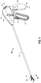
FIG. 1 is a perspective view of an endoscopic electrosurgical forceps configured for use in accordance with the present disclosure; -
FIG. 2A is an enlarged, perspective view of an end effector assembly of the forceps ofFIG. 1 with jaw members thereof disposed in a spaced-apart position; -
FIG. 2B is an enlarged, perspective view of the end effector assembly ofFIG. 2A with the jaw members thereof disposed in an approximated position; -
FIG. 3 is a perspective view of an open electrosurgical forceps configured for use in accordance with the present disclosure; -
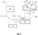
FIG. 4 is a schematic illustration of a robotic surgical system configured for use in accordance with the present disclosure; -
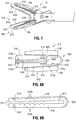
FIG. 5 is a perspective view of an adapter provided in accordance with the present disclosure including a surgical clip engaged therein; -
FIG. 6 is an exploded, perspective view illustrating coupling of the surgical clip ofFIG. 5 with the adapter ofFIG. 5 and the engagement thereof with the end effector assembly of the forceps ofFIG. 1 ; -
FIG. 7 is a side view illustrating engagement of the surgical clip and adapter ofFIG. 5 with the end effector assembly of the forceps ofFIG. 1 , wherein the jaw members of the end effector assembly are disposed in the spaced-apart position; -
FIG. 8A is a side view of the adapter and surgical clip ofFIG. 5 , wherein the adapter is disposed in a closed condition corresponding to a formed condition of the surgical clip; and -
FIG. 8B is a side view of the surgical clip ofFIG. 5 in the formed condition. - The present disclosure relates to adapters, systems incorporating such adapters, and methods for providing electrosurgical forceps with clip-applying functionality. Although particular electrosurgical forceps are detailed herein, it is contemplated that the adapters of the present disclosure be likewise configured for use with other suitable electrosurgical forceps and/or other surgical instruments, and that the present disclosure also encompasses systems including the presently-disclosed adapters and such instruments.
- Referring initially to
FIG. 1 , an endoscopic electrosurgical forceps configured for use in accordance with the present disclosure is shown generally identified byreference numeral 10.Forceps 10 generally includes ahousing 12, anelongated shaft 14 extending distally fromhousing 12, anend effector assembly 16 disposed at a distal end portion ofelongated shaft 14, amovable handle 22, atrigger 24, arotation knob 26, anactivation switch 28, and anelectrosurgical cable 30.End effector assembly 16 includes first andsecond jaw members -
Movable handle 22 is operably coupled tohousing 12 and movable relative to astationary handle portion 32 ofhousing 12 between an initial position and a compressed position. A drive assembly (not shown) extends throughhousing 12 andelongated shaft 14 and is operably coupled betweenmovable handle 22 and first andsecond jaw members end effector assembly 16 such that movement ofmovable handle 22 between the initial position and the compressed position pivots one or both ofjaw members FIG. 2A ) and an approximated position (FIG. 2B ). A suitable drive assembly for these purposes is detailed inU.S. Patent Application Pub. No. 2013/0296922 to Allen, IV et al. -
Trigger 24 is operably coupled tohousing 12 and movable relative thereto between an un-actuated position and an actuated position. A knife deployment assembly (not shown) extends throughhousing 12 andelongated shaft 14 and is operably coupled betweentrigger 24 and a knife 34 (FIG. 2A ) associated withend effector assembly 16 such that movement oftrigger 24 from the un-actuated position to the actuated position advancesknife 34 from a retracted position to an extended position, whereinknife 34 extends betweenjaw members FIG. 2A ). A knife deployment assembly for these purposes is detailed inU.S. Patent Application Pub. No. 2013/0296922 to Allen, IV et al. -
Rotation knob 26 is operably associated withhousing 12 and extends from either side thereof to enable manual manipulation by a user.Rotation knob 26 is coupled toelongated shaft 14 which, in turn, supportsend effector assembly 16 at a distal end portion thereof. As a result, rotation ofrotation knob 26 in either direction rotates elongatedshaft 14 andend effector assembly 16 relative tohousing 12 in a corresponding direction. -
Activation switch 28 is disposed onhousing 12, whileelectrosurgical cable 30 extends fromhousing 12.Electrosurgical cable 30 is adapted to connect to a source of energy, e.g., an electrosurgical generator (not shown), and includes a plurality of electrical lead wires (not shown) extending therethrough and intohousing 12. The electrical lead wires (not shown) are configured to electrically couple the electrosurgical generator withactivation switch 28 andjaw members end effector assembly 16 such that electrosurgical energy is supplied tojaw members activation switch 28. As an alternative toelectrosurgical cable 30 being adapted to connect to a remote electrosurgical generator,forceps 10 may be configured as a cordless, handheld instrument including power and energy-generation components disposed on or withinhousing 12. - With reference to
FIGS. 2A and 2B , as noted above,end effector assembly 16 is disposed at a distal end portion ofelongated shaft 14 and includes first andsecond jaw members jaw members elongated shaft 14 about apivot pin 36. For the purposes herein, "movement" or "pivoting" of thejaw members jaw members elongated shaft 14, and unilateral configurations, e.g., wherein onejaw member elongated shaft 14 and theother jaw member jaw member elongated shaft 14. Eachjaw member insulative housing surface insulative housing knife channel 42 ofjaw member 18b is shown) defined within the respective tissue-contactingsurface jaw members more stop members 44 operably associated with, e.g., disposed on, the tissue-contactingsurface surfaces jaw members - With
jaw members surfaces electrosurgical cable 30 upon activation ofactivation switch 28. Tissue-contactingsurfaces FIG. 1 ) is actuated to advanceknife 34 through longitudinally-extendingknife channels 42 ofjaw members knife 34 whenjaw members - Turning to
FIG. 3 , an open electrosurgical forceps configured for use in accordance with the present disclosure is shown generally identified byreference numeral 100.Forceps 100 includes first and secondelongated shafts proximal end portion distal end portion end effector assembly 108 offorceps 100 includes first andsecond jaw members distal end portions elongated shafts Elongated shafts pivot 103 such thatelongated shafts second jaw members pivot 103 and relative to one another from a spaced-apart position to an approximated position. - Each
elongated shaft handle proximal end portion handle finger hole elongated shafts - One of the elongated shafts, e.g.,
elongated shaft 102a, is configured to house a knife (not shown; similar toknife 34 of forceps 10 (FIG. 2A )) and knife deployment assembly (not shown), and includes atrigger 130 disposed on either side thereof. The knife deployment assembly (not shown) extends throughelongated shaft 102a and is operably coupled betweentriggers 130 andknife 34 such that movement of either oftriggers 130 from an un-actuated position to an actuated position advancesknife 34 from a retracted position to an extended position, whereinknife 34 extends betweenjaw members U.S. Patent Application Pub. No. 2012/0083786 to Artale et al. Forceps 100 may further include aknife lockout 140 to inhibit actuation ofknife 34 whenelongated shafts jaw members U.S. Patent Application Pub. No. 2012/0083827 to Artale et al. - Continuing with reference to
FIG. 3 ,elongated shaft 102b includes anactivation switch 150 disposed thereon at theproximal end portion 104b thereof.Activation switch 150 aligns with an opposingsurface 152 of theproximal end portion 104a ofelongated shaft 102a such that upon movement ofelongated shafts activation switch 150 is urged to an activated position via opposingsurface 152 ofelongated shaft 102a. Anelectrosurgical cable 160 extends from aproximal shaft connector 162 ofelongated shaft 102b.Electrosurgical cable 160 is adapted to connect to a source of energy, e.g., an electrosurgical generator (not shown), and includes a plurality of electrical lead wires (not shown) extending therethrough and intoelongated shaft 102b. The electrical lead wires (not shown) are configured to electrically couple the electrosurgical generator withactivation switch 150 andjaw members end effector assembly 108 such that electrosurgical energy is supplied tojaw members activation switch 150. -
Jaw members end effector assembly 108 offorceps 100 are similar to and may include any of the features ofjaw members end effector assembly 16 of forceps 10 (Figs. 1-2B ). Accordingly, for purposes of brevity,jaw members - Referring to
FIG. 4 , a robotic surgical system configured for use in accordance with the present disclosure is shown generally identified byreference numeral 1000. For the purposes herein, roboticsurgical system 1000 is generally described. Aspects and features of roboticsurgical system 1000 not germane to the understanding of the present disclosure are omitted to avoid obscuring the aspects and features of the present disclosure in unnecessary detail. - Robotic
surgical system 1000 generally includes a plurality ofrobot arms control device 1004; and anoperating console 1005 coupled withcontrol device 1004.Operating console 1005 may include adisplay device 1006, which may be set up in particular to display three-dimensional images; andmanual input devices robot arms surgical system 1000 may be configured for use on apatient 1013 lying on a patient table 1012 to be treated in a minimally invasive manner. Roboticsurgical system 1000 may further include adatabase 1014, in particular coupled to controldevice 1004, in which are stored, for example, pre-operative data frompatient 1013 and/or anatomical atlases. - Each of the
robot arms device end effector assembly End effector assembly 16 may be the end effector assembly of endoscopic surgical forceps 10 (FIG. 1 ), detailed above, or any other suitable end effector assembly. With respect to embodiments where one of the surgical tools "ST" isend effector assembly 16, roboticsurgical system 1000 functions as an electrosurgical forceps configured to manipulate and/or actuateend effector assembly 16 so as to enabling the grasping, treating, and dividing of tissue, similarly as detailed above with respect to forceps 10 (FIG. 1 ).End effector assembly 1100 may be any other suitable surgical end effector, e.g., an endoscopic camera, other surgical tool, etc.Robot arms device 1004.Control device 1004, e.g., a computer, may be configured to activate the motors, in particular by means of a computer program, in such a way thatrobot arms devices end effector assemblies 16, 1100) execute a desired movement and/or function according to a corresponding input frommanual input devices Control device 1004 may also be configured in such a way that it regulates the movement ofrobot arms - Endoscopic electrosurgical forceps 10 (
FIG. 1 ), open electrosurgical forceps 100 (FIG. 3 ), and robotic surgical system 1000 (FIG. 4 ) each include end effector assemblies capable of grasping tissue, treating tissue with electrosurgical energy, and dividing tissue. Provided in accordance with the present disclosure, and detailed below with reference toFIGS. 5-8B , is anadapter 500 configured for use with electrosurgical forceps 10 (FIG. 1 ), open electrosurgical forceps 100 (FIG. 3 ), robotic surgical system 1000 (FIG. 4 ), and/or any other suitable surgical instrument for providing such with clip-applying functionality. Thus, althoughadapter 500 is detailed below in use connection withend effector 16 offorceps 10, it is understood thatadapter 500 is equally applicable for use with any suitable surgical instrument to provide such with clip-applying functionality. - Referring to
FIGS. 5-8B ,adapter 500 includes a pair ofjaws bodies 510 coupled to one another via aninterconnect band 530.Adapter 500 may be monolithically formed as an integral component e.g., via injection molding, extrusion, etc., and may be constructed from plastic, althoughadapter 500 may alternatively define any other suitable configuration and/or be formed via any other suitable material(s) and/or manufacturing process(es). As detailed below,adapter 500 is configured to receive asurgical clip 600 therebetween and, in cooperation withend effector assembly 16, formsurgical clip 600 about tissue. Although one embodiment of asurgical clip 600 is detailed herein,adapter 500 may additionally or alternatively be configured for use with other surgical clips of varying size and/or configuration. -
Jaw bodies 510 define substantially similar configurations and, thus, are collectively referred to hereinbelow in the singular. However, in some embodiments, thejaw bodies 510 may define different configurations, e.g., whereadapter 500 is configured for use with a surgical clip having asymmetric legs. -
Jaw body 510 includes asupport plate 512 defining aproximal end portion 514 and adistal end portion 516, achuck 518 disposed on an inwardly-facing side ofsupport plate 512 towards thedistal end portion 516 thereof, and anelongated fin 520 disposed on an outwardly-facing side ofsupport plate 512 and extending fromproximal end portion 514 thereof longitudinally alongsupport plate 512.Support plate 512 defines an inwardly-facingsurface 513a, from whichchuck 518 extends, and an outwardly-facingsurface 513b, from which elongatedfin 520 extends. The exposed portion of outwardly-facingsurfaces 513b, e.g., the portions surroundingelongated fin 520, are configured to sit atop the tissue-contactingsurfaces corresponding jaw member end effector assembly 16 whenadapter 500 is engaged withend effector assembly 16. -
Chuck 518, as noted above, is disposed on the inwardly-facing side ofsupport plate 512 towardsdistal end portion 516 thereof.Chuck 518 may extend over about half (e.g., 40% to 60%) of the length ofsupport plate 512, although other configurations are also contemplated. Thus, a proximal half of inwardly-facingsurface 513a ofsupport plate 512 is exposed.Chuck 518 defines a longitudinally-extendingchannel 519a defined therethrough that is configured to receive a portion of aleg 610 ofsurgical clip 600 therein.Chuck 518 further includes a pair of spaced-apart feet 519b extending distally fromsupport plate 512. Eachfoot 519b defines asemi-circular recess 519c, each of which is configured to receive alocation knob 616 of one of thelegs 610 ofsurgical clip 600 to facilitate proper alignment and retention of theleg 610 of thesurgical clip 600 withinchannel 519a, as detailed below. -
Elongated fin 520, as noted above, is disposed on an outwardly-facing side ofsupport plate 512 and extends distally fromproximal end portion 514 thereof. However, as longitudinally-extendingknife channels 42 ofjaw members end effector assembly 16 do not extend all the way to the distal ends ofjaw members elongated fin 520 does not extend all the way to the distal end ofsupport plate 512. Further,elongated fin 520 defines a height profile that compliments a depth profile of theknife channel 42 of thecorresponding jaw member end effector assembly 16 to enable receipt ofelongated fin 520 therein.Elongated fin 520 further defines a width that generally approximates the width of thecorresponding knife channel 42 to minimize play therebetween. In some embodiment,elongated fin 520 may be configured for friction-fit engagement within the correspondingknife channel 42. Alternatively, retention of thejaw bodies 510 in engagement with thecorresponding jaw members interconnect band 530, as detailed below. -
Interconnect band 530 defines an arcuate configuration and extends proximally fromproximal end portion 514 ofsupport plate 512 of eachjaw body 510. In an initial at-rest position ofadapter 500,interconnect band 530 defines a first radius of curvature. In response to urging of either or both ofjaw bodies 510 towards the other,interconnect band 530 is configured to flex such thatadapter 500 is moved from the at-rest position to a flexed position, whereinjaw bodies 510 are disposed in closer approximation relative to one another andinterconnect band 530 defines a second, reduced radius of curvature.Interconnect band 530 may be resiliently flexible such that, upon removal of forces thereon,interconnect band 530 returnsadapter 500 to the at-rest position, thus enabling multiple uses for applying a plurality ofsurgical clips 600, or may be partially-resilient such thatinterconnect band 530 returnsadapter 500 to an intermediate position upon removal of forces thereon to enableadapter 500 to be withdrawn from aboutsurgical clip 600 without returningadapter 500 to the at-rest position. In such partially-resilient configurations,adapter 500 may be configured for single-use. - In the at-rest position of
adapter 500,interconnect band 530, as noted above, defines a first radius of curvature. This first radius of curvature may correspond to an angle betweenjaw bodies 510 that is greater than an angle betweenjaw members end effector assembly 16 in a furthest spaced-apart position ofjaw members interconnect band 530 is required to be flexed towards the flexed position ofadapter 500 upon insertion ofadapter 500 betweenjaw members adapter 500 installed betweenjaw members jaw members adapter 500 is disposed in a pre-compressed condition. As a result,jaw bodies 510 are urged towards the correspondingjaw members jaw body 510 in operable engagement with thecorresponding jaw member - In order to operably engage
adapter 500 withend effector assembly 16,jaw members Adapter 500, lead byinterconnect band 530, is then translated proximally betweenjaw members fins 520 aligned withknife channels 42. Asadapter 500 is translated proximally, due to the angle betweenjaw bodies 510 in the at-rest position ofadapter 500 being greater than the angle betweenjaw members jaw members jaw bodies 510 ofadapter 500 are eventually urged towards one another beyond the pre-compressed condition ofadapter 500. Oncefins 520 clear the distal end portions of tissue-contactingsurface jaw members knife channels 42 along the entire lengths offins 520,jaw bodies 510 are resiliently returned towards the initial position ofadapter 500 under the bias ofinterconnect band 530. This bias ofjaw bodies 510 towards the at-rest position ofadapter 500urges fins 520 intoknife channels 42 until outwardly-facingsurfaces 513b ofsupport plates 514 ofjaw bodies 510 abut tissue-contactingsurfaces jaw members adapter 500 is not returned to the at-rest position when operably engaged withend effector assembly 16 but, rather, is retained therein in a pre-compressed condition, thus facilitating retention ofadapter 500 in operable engagement withend effector assembly 16.Surgical clip 600 may be installed onadapter 500 prior to or subsequent ofadapter 500 being operably engaged withend effector assembly 16. - Continuing with reference to
FIGS. 5-8B ,surgical clip 600 includes a pair oflegs 610 interconnected by abackspan 620.Surgical clip 600 may be monolithically formed as a single component from a suitable metal, plastic, or other suitable material, or may be a multicomponent clip. Although one configuration of asurgical clip 600 is detailed herein, other suitable surgical clips may also be provided such as, for example, the surgical clips detailed inU.S. Patent Nos. 4,834,096 ;7,819,886 ; and7,905,890 . - Each
leg 610 ofsurgical clip 600 defines a generally rectangular cross-sectional configuration, although other configurations may alternatively be provided, and has a width that generally approximates the width of thechannel 519a of thechuck 518 of thecorresponding jaw body 510 of adapter such that a portion of eachleg 610 is receivable within the correspondingchannel 519a. Eachleg 610 further defines a fixedproximal end portion 612 and a freedistal end portion 614. Alocation knob 616 extends transversely from either side of eachleg 610 at thedistal end portion 614 thereof. Location knobs 616 are configured for receipt withinrecesses 519c offeet 519b ofchucks 518 of thecorresponding jaw bodies 510 so as to retainsurgical clip 600 in operable engagement with and proper orientation relative toadapter 500.Legs 610 may further include a series ofcomplementary grooves 618a andribs 618b disposed on inwardly-facing surfaces thereof and configured to mate with one another in the formed position ofsurgical clip 600, thus facilitating alignment oflegs 610 in the formed position ofsurgical clip 600. -
Backspan 620 ofsurgical clip 600 extends proximally from and interconnectsproximal end portions 612 oflegs 610.Backspan 620 defines an arcuate configuration and is deformable from an initial condition ofsurgical clip 600, wherein backspan 620 defines a first radius of curvature, to a formed condition ofsurgical clip 600, wherein backspan 620 defines a second radius of curvature less than the first radius of curvature. In the initial condition ofsurgical clip 600, backspan 620 exhibits resiliency through an initial range of motion such that, backspan 620 biasessurgical clip 600 towards the initial condition upon urging oflegs 610 towards one another within the initial range of motion. However, backspan 620 is permanently deformable once the initial range of motion has been exceeded such thatsurgical clip 600 is maintained in the formed condition after reaching the formed condition. The initial resilience ofbackspan 620 enablessurgical clip 600 to be pre-compressed upon positioning withinadapter 500 to retainsurgical clip 600 therein, similarly as detailed above with respect toadapter 500 andjaw members backspan 620 may exhibit resiliency through the entire range of motion oflegs 610. In such configurations,legs 610 may include mechanical engagement features (not shown) at the distal endsportions 614 thereof to mechanically locksurgical clip 600 in the formed condition upon achieving the formed condition. - In order to engage
surgical clip 600 withadapter 500,surgical clip 600, lead bybackspan 620 is translated proximally betweenjaw bodies 510 ofadapter 500 withlegs 610 aligned withchannels 519a ofchucks 518 ofjaw bodies 510. Assurgical clip 600 is translated proximally, or prior thereto,legs 610 ofsurgical clip 600 are moved towards one another to permit receipt oflegs 610 ofsurgical clip 600 betweenjaw bodies 510 ofadapter 500.Surgical clip 600 is translated proximally relative toadapter 500 until location knobs 616 oflegs 610 ofsurgical clip 600 are aligned withrespective recesses 519c ofjaw bodies 510 ofadapter 500. Once this alignment has been achieved,surgical clip 600 may be released to return towards the initial condition. This bias oflegs 610 towards the initial condition ofsurgical clip 600 urgeslegs 610 intochannels 519a and urgeslocation knobs 616 intorecesses 519c. As noted above,surgical clip 600 is not returned to the initial condition when engaged withadapter 500 but, rather, is retained therein in a pre-compressed condition, thus facilitating retention ofsurgical clip 600 in engagement withadapter 500 prior to formation thereof. - With general reference to
FIGS. 1- 2B forceps 10, as noted above, may be used to grasp tissue between tissue-contactingsurfaces FIGS. 5-8B , where, during the course of a surgical procedure, it is necessary to apply asurgical clip 600,adapter 500 may be operably engaged withend effector assembly 16, as detailed above. As also noted above,surgical clip 600 may be loaded intoadapter 500 prior to or subsequent of operable engagement ofadapter 500 withend effector assembly 16. - With
adapter 500 andsurgical clip 600 operably engaged with one another and endeffector assembly 16,forceps 10 may be utilized to formsurgical clip 600 about tissue. In order to formsurgical clip 600 about tissue,movable handle 22 is moved relative tostationary handle portion 32 ofhousing 12 from the initial position towards the compressed position such that the drive assembly (not shown) urgesjaw members end effector assembly 16 to pivot from the spaced-apart position (FIGS. 2A and7 ) towards and the approximated position (FIG. 2B ). Asjaw members surfaces jaw members urge support plates 512 ofjaw bodies 510 ofadapter 500 towards one another, thereby urgingadapter 500 towards the flexed position. Urging ofadapter 500 towards the flexed position, in turn, urgeslegs 610 ofsurgical clip 600 towards one another to the formed condition ofsurgical clip 600.Movable handle 22 is moved sufficiently towards the compressed position to achieve the fully-flexed position ofadapter 500 corresponding to the fully-formed condition ofsurgical clip 600, whereinlegs 610 of surgical clip terminate the flow of fluid through the tissue about whichsurgical clip 600 formed. - Once
surgical clip 600 is moved to the deformed condition (seeFIGS. 8A and 8B ) to terminate the flow of fluid through the tissue,jaw members movable handle 22, and, thereafter,end effector assembly 16 andadapter 500 may be removed, leaving behindsurgical clip 600. Further application ofsurgical clips 600 usingadapter 500 and endeffector assembly 16 and/or further grasping, treating, and dividing of tissue usingend effector assembly 16 may then be effectuated, depending upon the particular procedure to be performed. - In some embodiments, after formation of
surgical clip 600 about tissue, tissue-contactingsurfaces surgical clip 600, e.g., via activation of activation switch 28 (FIG. 1 ). In some embodiments, one or more sensors "S" (FIGS. 2A and 2B ), e.g., mechanical switches, electrical sensors, optical sensors, etc., disposed within either or both ofjaw members adapter 500 withend effector assembly 16. Such sensors "S" may further be configured to communicate with activation switch 28 (FIG. 1 ) and/or the electrosurgical generator to inhibit the supply of energy to tissue-contactingsurfaces adapter 500 is engaged therein, or to signal the electrosurgical generator to supply a suitable energy for use in treating tissue surroundingsurgical clip 600 upon activation of activation switch 28 (FIG. 1 ). - With reference to
FIGS. 4 and5 , in embodiments where roboticsurgical system 1000 is utilized,end effector assembly 1100 may be configured to retain anadapter 500 and one or moresurgical clips 600 to enable automatic loading ofadapter 500 and asurgical clip 600 withinend effector assembly 16 and to enable automatic replacement of thesurgical clip 600 with a secondsurgical clip 600 after formation of the firstsurgical clip 600. - While several embodiments of the disclosure have been shown in the drawings, it is not intended that the disclosure be limited thereto, as it is intended that the disclosure be as broad in scope as the art will allow and that the specification be read likewise. Therefore, the above description should not be construed as limiting, but merely as examples of particular embodiments. Those skilled in the art will envision other modifications within the scope of the claims appended hereto.
- Although the foregoing disclosure has been described in some detail by way of illustration and example, for purposes of clarity or understanding, it will be obvious that certain changes and modifications may be practiced within the scope of the appended claims.
Claims (15)
- A surgical system, comprising:a surgical forceps (10) including an end effector assembly (16) including a pair of jaw members (18a, 18b) each defining a tissue-contacting surface, the jaw members movable from a spaced-apart position to an approximated position;an adapter (500) releasably engageable with the end effector assembly, the adapter including a pair of jaw bodies (510) and an interconnect band (530) coupling the jaw bodies with one another, each jaw body including a support plate (512) configured for positioning on the tissue-contacting surface of one of the jaw members, and a chuck (518); anda surgical clip (600) releasably engageable with the adapter, the surgical clip including a pair of legs (610) and a backspan (620) interconnecting the legs, each leg configured for receipt at least partially within the chuck of one of the jaw bodies of the adapter,wherein, with the surgical clip engaged with the adapter and the adapter engaged with the end effector assembly, the jaw members are configured to move from the spaced-apart position towards the approximated position to move the jaw bodies towards one another to, in turn, urge the legs of the surgical clip towards one another to form the surgical clip,wherein the surgical forceps further includes a knife (34) selectively translatable relative to the jaw members between a retracted position and an extended position, wherein the knife extends at least partially through a knife channel (42) defined within and extending longitudinally through at least one of the tissue-contacting surfaces, and wherein the at least one of the jaw bodies of the adapter includes a fin (520) configured for receipt within the knife channel of one of the jaw members.
- The surgical system according to claim 1, wherein the tissue contacting surface of at least one of the jaw members is adapted to connect to a source of electrosurgical energy.
- The surgical system according to claim 1 or 2, wherein the chuck of each jaw body defines a channel (519a) configured to receive a portion of one of the legs of the surgical clip therein.
- The surgical system according to claim 1, 2 or 3, wherein the chuck of each jaw body defines at least one location feature (519c), and wherein each leg of the surgical clip defines at least one complementary location feature (616) configured to engage the at least one location feature to facilitate alignment of the surgical clip relative to the adapter.
- The surgical system according to claim 4, wherein the at least one location feature is at least one recess and wherein the at least one complementary location feature is at least one knob (616) configured for engagement within the at least one recess.
- The surgical system according to claim 4 or 5, wherein the chuck of each jaw body includes a pair of spaced-apart feet (519b) configured to receive a portion of the surgical clip therebetween, each foot defining one of the at least one location features.
- The surgical system according to any preceding claim, wherein the adapter is engaged in a pre-compressed position within the end effector assembly.
- The surgical system according to claim 7, wherein the adapter defines an at-rest position wherein the interconnect band defines a first radius of curvature, and wherein, when the adapter is engaged with the end effector assembly, the adapter is retained in the pre-compressed position wherein the interconnect band is flexed to define a second radius of curvature smaller than the first radius of curvature.
- The surgical system according to any preceding claim, wherein the surgical clip is engaged in a pre-compressed position within the adapter.
- The surgical system according to claim 9, wherein the surgical clip defines an initial condition wherein the backspan defines a first radius of curvature, and wherein, when the surgical clip is engaged with the adapter, the surgical clip is retained in the pre-compressed condition wherein the backspan is flexed to define a second radius of curvature smaller than the first radius of curvature.
- An adapter (500) configured for use with a surgical instrument to provide clip-applying functionality thereto, the adapter comprising:a pair of jaw bodies (510), each jaw body including:a support plate (512) defining an inwardly-facing side, an outwardly-facing side, a proximal end portion, and a distal end portion;a fin (520) extending longitudinally along a portion of the outwardly-facing side of the support plate and configured for receipt within a knife channel (42) of one of a pair of jaw members (18a, 18b) of the surgical instrument; anda chuck (518) disposed on the inwardly-facing side of the support plate, the chuck defining a channel (519a) and at least one location feature (519c); andan interconnect band (530) extending between and coupling the proximal end portions of the support plates of the jaw bodies with one another, wherein the interconnect band is configured to flex from an at-rest position, corresponding to a further-spaced position of the jaw bodies, to a flexed position, corresponding to a closer-approximated position of the jaw bodies,wherein, with legs (610) of a surgical clip (600) received with the channels of the chucks and complementary location features (616) of the legs of the surgical clip received within the at least one location feature of each of the chucks, movement of the jaw bodies from the further-spaced position towards the closer-approximated position moves the legs of the surgical clip from an initial condition towards a formed condition, preferably wherein the jaw bodies and the interconnect band are a monolithic component.
- The surgical system according to claim 11, wherein the interconnect band (530) is resiliently flexible such that, upon removal of forces thereon, the interconnect band (530) returns the adapter (500) to the at-rest position or to an intermediate position between the at-rest position and the flexed position.
- The adapter according to claim 11 or 12, wherein the chucks are disposed towards the distal end portions of the support plates such that a proximal portion of an inwardly-facing surface of each of the support plates is exposed.
- The adapter according to claim 11, 12 or 13 wherein the fins extend from the proximal end portions of the support plates to points proximal of the distal end portions of the support plates.
- The adapter according to claim 11, 12, 13 or 14 wherein each chuck includes a pair of spaced-apart feet (519b), and wherein each foot defines one of the at least one location features therein.
Applications Claiming Priority (1)
| Application Number | Priority Date | Filing Date | Title |
|---|---|---|---|
| US15/428,609 US10881445B2 (en) | 2017-02-09 | 2017-02-09 | Adapters, systems incorporating the same, and methods for providing an electrosurgical forceps with clip-applying functionality |
Publications (3)
| Publication Number | Publication Date |
|---|---|
| EP3360498A2 EP3360498A2 (en) | 2018-08-15 |
| EP3360498A3 EP3360498A3 (en) | 2018-10-17 |
| EP3360498B1 true EP3360498B1 (en) | 2020-04-01 |
Family
ID=61188697
Family Applications (1)
| Application Number | Title | Priority Date | Filing Date |
|---|---|---|---|
| EP18155801.6A Active EP3360498B1 (en) | 2017-02-09 | 2018-02-08 | Adapters and systems incorporating the same for providing an electrosurgical forceps with clip-applying functionality |
Country Status (3)
| Country | Link |
|---|---|
| US (1) | US10881445B2 (en) |
| EP (1) | EP3360498B1 (en) |
| CN (1) | CN208989120U (en) |
Families Citing this family (1)
| Publication number | Priority date | Publication date | Assignee | Title |
|---|---|---|---|---|
| JP2024017839A (en) * | 2022-07-28 | 2024-02-08 | 株式会社メディカロイド | Surgical instruments and surgical support robots |
Family Cites Families (208)
| Publication number | Priority date | Publication date | Assignee | Title |
|---|---|---|---|---|
| SU401367A1 (en) | 1971-10-05 | 1973-10-12 | Тернопольский государственный медицинский институт | BIAKTIVNYE ELECTRO SURGICAL INSTRUMENT |
| DE2415263A1 (en) | 1974-03-29 | 1975-10-02 | Aesculap Werke Ag | Surgical H.F. coagulation probe has electrode tongs - with exposed ends of insulated conductors forming tong-jaws |
| DE2514501A1 (en) | 1975-04-03 | 1976-10-21 | Karl Storz | Bipolar coagulation instrument for endoscopes - has two high frequency electrodes looped over central insulating piece |
| FR2315286A2 (en) | 1975-06-26 | 1977-01-21 | Lamidey Marcel | H.F. blood coagulating dissecting forceps - with adjustable stops to vary clamping space and circuit making contacts |
| USD249549S (en) | 1976-10-22 | 1978-09-19 | Aspen Laboratories, Inc. | Electrosurgical handle |
| US4294355A (en) | 1979-12-06 | 1981-10-13 | Ethicon, Inc. | Cartridge for hemostatic clips |
| USD263020S (en) | 1980-01-22 | 1982-02-16 | Rau Iii David M | Retractable knife |
| US4361229A (en) | 1981-08-03 | 1982-11-30 | Ethicon, Inc. | Cartridge for hemostatic clips |
| US4570633A (en) | 1981-09-28 | 1986-02-18 | Ethicon, Inc. | Surgical clip applier instrument adapter jaws |
| US4509518A (en) * | 1982-02-17 | 1985-04-09 | United States Surgical Corporation | Apparatus for applying surgical clips |
| JPS61501068A (en) | 1984-01-30 | 1986-05-29 | ハルコフスキイ ナウチノ−イススレドワテルスキイ インスチチユ−ト オブスチエイ イ ネオトロジノイ ヒルルギイ | bipolar electrosurgical instrument |
| DE3423356C2 (en) | 1984-06-25 | 1986-06-26 | Berchtold Medizin-Elektronik GmbH & Co, 7200 Tuttlingen | Electrosurgical high frequency cutting instrument |
| US4657016A (en) | 1984-08-20 | 1987-04-14 | Garito Jon C | Electrosurgical handpiece for blades, needles and forceps |
| USD299413S (en) | 1985-07-17 | 1989-01-17 | The Stanley Works | Folding pocket saw handle |
| USD295893S (en) | 1985-09-25 | 1988-05-24 | Acme United Corporation | Disposable surgical clamp |
| USD295894S (en) | 1985-09-26 | 1988-05-24 | Acme United Corporation | Disposable surgical scissors |
| DE3627221A1 (en) | 1986-01-15 | 1988-02-18 | Siemens Ag | HF surgical instrument with performance control from the surgical handle |
| USD298353S (en) | 1986-05-06 | 1988-11-01 | Vitalmetrics, Inc. | Handle for surgical instrument |
| DE8712328U1 (en) | 1987-09-11 | 1988-02-18 | Jakoubek, Franz, 7201 Emmingen-Liptingen, De | |
| US4834096A (en) | 1987-10-26 | 1989-05-30 | Edward Weck Incorporated | Plastic ligating clips |
| US5026379A (en) | 1989-12-05 | 1991-06-25 | Inbae Yoon | Multi-functional instruments and stretchable ligating and occluding devices |
| JP2806511B2 (en) | 1990-07-31 | 1998-09-30 | 松下電工株式会社 | Manufacturing method of sintered alloy |
| US5389102A (en) | 1990-09-13 | 1995-02-14 | United States Surgical Corporation | Apparatus and method for subcuticular stapling of body tissue |
| US5190541A (en) | 1990-10-17 | 1993-03-02 | Boston Scientific Corporation | Surgical instrument and method |
| JP2951418B2 (en) | 1991-02-08 | 1999-09-20 | トキコ株式会社 | Sample liquid component analyzer |
| US5324289A (en) | 1991-06-07 | 1994-06-28 | Hemostatic Surgery Corporation | Hemostatic bi-polar electrosurgical cutting apparatus and methods of use |
| USD348930S (en) | 1991-10-11 | 1994-07-19 | Ethicon, Inc. | Endoscopic stapler |
| US5201900A (en) * | 1992-02-27 | 1993-04-13 | Medical Scientific, Inc. | Bipolar surgical clip |
| JPH0630945A (en) | 1992-05-19 | 1994-02-08 | Olympus Optical Co Ltd | Suturing apparatus |
| USD349341S (en) | 1992-10-28 | 1994-08-02 | Microsurge, Inc. | Endoscopic grasper |
| DE4303882C2 (en) | 1993-02-10 | 1995-02-09 | Kernforschungsz Karlsruhe | Combination instrument for separation and coagulation for minimally invasive surgery |
| JP3390041B2 (en) | 1993-04-05 | 2003-03-24 | オリンパス光学工業株式会社 | Forceps |
| JP3585491B2 (en) | 1993-04-30 | 2004-11-04 | メディカル サイエンティフィク インコーポレイテッド | Impedance feedback electrosurgical system |
| GB9309142D0 (en) | 1993-05-04 | 1993-06-16 | Gyrus Medical Ltd | Laparoscopic instrument |
| USD343453S (en) | 1993-05-05 | 1994-01-18 | Laparomed Corporation | Handle for laparoscopic surgical instrument |
| USD354564S (en) | 1993-06-25 | 1995-01-17 | Richard-Allan Medical Industries, Inc. | Surgical clip applier |
| US5688270A (en) | 1993-07-22 | 1997-11-18 | Ethicon Endo-Surgery,Inc. | Electrosurgical hemostatic device with recessed and/or offset electrodes |
| US5693051A (en) | 1993-07-22 | 1997-12-02 | Ethicon Endo-Surgery, Inc. | Electrosurgical hemostatic device with adaptive electrodes |
| GB9322464D0 (en) | 1993-11-01 | 1993-12-22 | Gyrus Medical Ltd | Electrosurgical apparatus |
| USD358887S (en) | 1993-12-02 | 1995-05-30 | Cobot Medical Corporation | Combined cutting and coagulating forceps |
| DE4403252A1 (en) | 1994-02-03 | 1995-08-10 | Michael Hauser | Instrument shaft for min. invasive surgery |
| GB9413070D0 (en) | 1994-06-29 | 1994-08-17 | Gyrus Medical Ltd | Electrosurgical apparatus |
| USD384413S (en) | 1994-10-07 | 1997-09-30 | United States Surgical Corporation | Endoscopic suturing instrument |
| GB9425781D0 (en) | 1994-12-21 | 1995-02-22 | Gyrus Medical Ltd | Electrosurgical instrument |
| DE19506363A1 (en) | 1995-02-24 | 1996-08-29 | Frost Lore Geb Haupt | Non-invasive thermometry in organs under hyperthermia and coagulation conditions |
| JPH08289895A (en) | 1995-04-21 | 1996-11-05 | Olympus Optical Co Ltd | Suture device |
| DE19515914C1 (en) | 1995-05-02 | 1996-07-25 | Aesculap Ag | Tong or scissor-shaped surgical instrument |
| JPH09538A (en) | 1995-06-21 | 1997-01-07 | Fuji Photo Optical Co Ltd | High-frequency medical treatment instrument |
| US6293942B1 (en) | 1995-06-23 | 2001-09-25 | Gyrus Medical Limited | Electrosurgical generator method |
| JPH1024051A (en) | 1995-09-20 | 1998-01-27 | Olympus Optical Co Ltd | Coagulation forceps with separating function |
| USH1745H (en) | 1995-09-29 | 1998-08-04 | Paraschac; Joseph F. | Electrosurgical clamping device with insulation limited bipolar electrode |
| AU703455B2 (en) | 1995-10-20 | 1999-03-25 | Ethicon Endo-Surgery, Inc. | Self protecting knife for curved jaw surgical instruments |
| US5673842A (en) | 1996-03-05 | 1997-10-07 | Ethicon Endo-Surgery | Surgical stapler with locking mechanism |
| DE19608716C1 (en) | 1996-03-06 | 1997-04-17 | Aesculap Ag | Bipolar surgical holding instrument |
| USD408018S (en) | 1996-03-12 | 1999-04-13 | Mcnaughton Patrick J | Switch guard |
| USD416089S (en) | 1996-04-08 | 1999-11-02 | Richard-Allan Medical Industries, Inc. | Endoscopic linear stapling and dividing surgical instrument |
| DE29616210U1 (en) | 1996-09-18 | 1996-11-14 | Winter & Ibe Olympus | Handle for surgical instruments |
| US5923475A (en) | 1996-11-27 | 1999-07-13 | Eastman Kodak Company | Laser printer using a fly's eye integrator |
| JP3836551B2 (en) | 1996-12-04 | 2006-10-25 | ペンタックス株式会社 | Endoscopic hot biopsy forceps |
| US5891142A (en) | 1996-12-06 | 1999-04-06 | Eggers & Associates, Inc. | Electrosurgical forceps |
| USH1904H (en) | 1997-05-14 | 2000-10-03 | Ethicon Endo-Surgery, Inc. | Electrosurgical hemostatic method and device |
| USH2037H1 (en) | 1997-05-14 | 2002-07-02 | David C. Yates | Electrosurgical hemostatic device including an anvil |
| JP3986126B2 (en) | 1997-08-04 | 2007-10-03 | オリンパス株式会社 | Endoscopic surgical instrument |
| JP3986127B2 (en) | 1997-08-06 | 2007-10-03 | オリンパス株式会社 | Endoscopic surgical instrument |
| DE19738457B4 (en) | 1997-09-03 | 2009-01-02 | Celon Ag Medical Instruments | Method and device for in vivo deep coagulation of biological tissue volumes while sparing the tissue surface with high frequency alternating current |
| USD402028S (en) | 1997-10-10 | 1998-12-01 | Invasatec, Inc. | Hand controller for medical system |
| US5980510A (en) | 1997-10-10 | 1999-11-09 | Ethicon Endo-Surgery, Inc. | Ultrasonic clamp coagulator apparatus having improved clamp arm pivot mount |
| DE19751108A1 (en) | 1997-11-18 | 1999-05-20 | Beger Frank Michael Dipl Desig | Electrosurgical operation tool, especially for diathermy |
| JPH11169381A (en) | 1997-12-15 | 1999-06-29 | Olympus Optical Co Ltd | High frequency treating device |
| EP0923907A1 (en) | 1997-12-19 | 1999-06-23 | Gyrus Medical Limited | An electrosurgical instrument |
| JP4225624B2 (en) | 1998-08-27 | 2009-02-18 | オリンパス株式会社 | High frequency treatment device |
| USD425201S (en) | 1998-10-23 | 2000-05-16 | Sherwood Services Ag | Disposable electrode assembly |
| AU756626B2 (en) | 1998-10-23 | 2003-01-16 | Covidien Ag | Open vessel sealing forceps with disposable electrodes |
| USD449886S1 (en) | 1998-10-23 | 2001-10-30 | Sherwood Services Ag | Forceps with disposable electrode |
| USD424694S (en) | 1998-10-23 | 2000-05-09 | Sherwood Services Ag | Forceps |
| DE19858512C1 (en) | 1998-12-18 | 2000-05-25 | Storz Karl Gmbh & Co Kg | Bipolar medical instrument for minimally invasive surgery for endoscopic operations; has mutually insulated leads passing through tubular shaft to conductor elements on linked jaw parts |
| DE19915061A1 (en) | 1999-04-01 | 2000-10-26 | Erbe Elektromedizin | Surgical instrument |
| GB9911956D0 (en) | 1999-05-21 | 1999-07-21 | Gyrus Medical Ltd | Electrosurgery system and method |
| GB9911954D0 (en) | 1999-05-21 | 1999-07-21 | Gyrus Medical Ltd | Electrosurgery system and instrument |
| GB9912625D0 (en) | 1999-05-28 | 1999-07-28 | Gyrus Medical Ltd | An electrosurgical generator and system |
| GB9912627D0 (en) | 1999-05-28 | 1999-07-28 | Gyrus Medical Ltd | An electrosurgical instrument |
| GB9913652D0 (en) | 1999-06-11 | 1999-08-11 | Gyrus Medical Ltd | An electrosurgical generator |
| JP2001003400A (en) | 1999-06-21 | 2001-01-09 | Sumitomo Constr Mach Co Ltd | Monitor device for hydraulic shovel |
| JP2001029355A (en) | 1999-07-21 | 2001-02-06 | Olympus Optical Co Ltd | Electric cautery device |
| DE19940689A1 (en) | 1999-08-27 | 2001-04-05 | Storz Karl Gmbh & Co Kg | Bipolar medical instrument |
| USD465281S1 (en) | 1999-09-21 | 2002-11-05 | Karl Storz Gmbh & Co. Kg | Endoscopic medical instrument |
| DE19946527C1 (en) | 1999-09-28 | 2001-07-12 | Storz Karl Gmbh & Co Kg | Bipolar, e.g. laparoscopic surgery instrument, cuts electrically, cauterizes and grips using simple design with high frequency current-concentrating projections |
| JP4315557B2 (en) | 2000-01-12 | 2009-08-19 | オリンパス株式会社 | Medical treatment tool |
| DE10003020C2 (en) | 2000-01-25 | 2001-12-06 | Aesculap Ag & Co Kg | Bipolar barrel instrument |
| DE10031773B4 (en) | 2000-05-04 | 2007-11-29 | Erbe Elektromedizin Gmbh | Surgical gripping instrument, in particular tweezers or forceps |
| DE10027727C1 (en) | 2000-06-03 | 2001-12-06 | Aesculap Ag & Co Kg | Scissors-shaped or forceps-shaped surgical instrument |
| DE10045375C2 (en) | 2000-09-14 | 2002-10-24 | Aesculap Ag & Co Kg | Medical instrument |
| EP1331887A4 (en) | 2000-10-20 | 2006-07-12 | Dvl Acquisition Sub Inc | Surgical suturing instrument and method of use |
| JP3523839B2 (en) | 2000-10-30 | 2004-04-26 | オリンパス株式会社 | Surgical instruments |
| USD453923S1 (en) | 2000-11-16 | 2002-02-26 | Carling Technologies, Inc. | Electrical rocker switch guard |
| DE10061278B4 (en) | 2000-12-08 | 2004-09-16 | GFD-Gesellschaft für Diamantprodukte mbH | Instrument for surgical purposes |
| US20020111624A1 (en) | 2001-01-26 | 2002-08-15 | Witt David A. | Coagulating electrosurgical instrument with tissue dam |
| DE20121161U1 (en) | 2001-01-31 | 2002-04-04 | Winter & Ibe Olympus | Endoscopic instrument |
| USD454951S1 (en) | 2001-02-27 | 2002-03-26 | Visionary Biomedical, Inc. | Steerable catheter |
| USD466209S1 (en) | 2001-02-27 | 2002-11-26 | Visionary Biomedical, Inc. | Steerable catheter |
| USD457958S1 (en) | 2001-04-06 | 2002-05-28 | Sherwood Services Ag | Vessel sealer and divider |
| USD457959S1 (en) | 2001-04-06 | 2002-05-28 | Sherwood Services Ag | Vessel sealer |
| FR2828248B1 (en) | 2001-08-02 | 2003-11-14 | Peugeot Citroen Automobiles Sa | PIVOT LINK BETWEEN TWO PARTS |
| JP2003116871A (en) | 2001-10-16 | 2003-04-22 | Olympus Optical Co Ltd | Surgical tool |
| US6676660B2 (en) | 2002-01-23 | 2004-01-13 | Ethicon Endo-Surgery, Inc. | Feedback light apparatus and method for use with an electrosurgical instrument |
| EP1795140B1 (en) | 2002-10-04 | 2017-02-22 | Covidien AG | Electrode assembly for sealing and cutting tissue |
| US7276068B2 (en) | 2002-10-04 | 2007-10-02 | Sherwood Services Ag | Vessel sealing instrument with electrical cutting mechanism |
| JP2003175052A (en) | 2002-11-01 | 2003-06-24 | Olympus Optical Co Ltd | Coagulation treatment tool |
| USD493888S1 (en) | 2003-02-04 | 2004-08-03 | Sherwood Services Ag | Electrosurgical pencil with pistol grip |
| USD499181S1 (en) | 2003-05-15 | 2004-11-30 | Sherwood Services Ag | Handle for a vessel sealer and divider |
| USD496997S1 (en) | 2003-05-15 | 2004-10-05 | Sherwood Services Ag | Vessel sealer and divider |
| USD502994S1 (en) | 2003-05-21 | 2005-03-15 | Blake, Iii Joseph W | Repeating multi-clip applier |
| US7156846B2 (en) | 2003-06-13 | 2007-01-02 | Sherwood Services Ag | Vessel sealer and divider for use with small trocars and cannulas |
| US7150749B2 (en) | 2003-06-13 | 2006-12-19 | Sherwood Services Ag | Vessel sealer and divider having elongated knife stroke and safety cutting mechanism |
| USD545432S1 (en) | 2003-08-08 | 2007-06-26 | Olympus Corporation | Distal portion of hemostatic forceps for endoscope |
| USD509297S1 (en) | 2003-10-17 | 2005-09-06 | Tyco Healthcare Group, Lp | Surgical instrument |
| US7442193B2 (en) | 2003-11-20 | 2008-10-28 | Covidien Ag | Electrically conductive/insulative over-shoe for tissue fusion |
| JP4624697B2 (en) | 2004-03-12 | 2011-02-02 | オリンパス株式会社 | Surgical instrument |
| USD541938S1 (en) | 2004-04-09 | 2007-05-01 | Sherwood Services Ag | Open vessel sealer with mechanical cutter |
| JP2005312807A (en) | 2004-04-30 | 2005-11-10 | Olympus Corp | Energy therapy device |
| DE102004026179B4 (en) | 2004-05-14 | 2009-01-22 | Erbe Elektromedizin Gmbh | Electrosurgical instrument |
| USD533942S1 (en) | 2004-06-30 | 2006-12-19 | Sherwood Services Ag | Open vessel sealer with mechanical cutter |
| JP2006015078A (en) | 2004-07-05 | 2006-01-19 | Olympus Corp | Medical apparatus |
| DE102004040959B4 (en) | 2004-08-24 | 2008-12-24 | Erbe Elektromedizin Gmbh | Surgical instrument |
| USD525361S1 (en) | 2004-10-06 | 2006-07-18 | Sherwood Services Ag | Hemostat style elongated dissecting and dividing instrument |
| USD531311S1 (en) | 2004-10-06 | 2006-10-31 | Sherwood Services Ag | Pistol grip style elongated dissecting and dividing instrument |
| USD535027S1 (en) | 2004-10-06 | 2007-01-09 | Sherwood Services Ag | Low profile vessel sealing and cutting mechanism |
| USD541418S1 (en) | 2004-10-06 | 2007-04-24 | Sherwood Services Ag | Lung sealing device |
| ES2547214T3 (en) | 2004-10-08 | 2015-10-02 | Covidien Lp | An endoscopic clip or surgical clip applicator |
| USD567943S1 (en) | 2004-10-08 | 2008-04-29 | Sherwood Services Ag | Over-ratchet safety for a vessel sealing instrument |
| US7819886B2 (en) | 2004-10-08 | 2010-10-26 | Tyco Healthcare Group Lp | Endoscopic surgical clip applier |
| USD533274S1 (en) | 2004-10-12 | 2006-12-05 | Allegiance Corporation | Handle for surgical suction-irrigation device |
| USD564662S1 (en) | 2004-10-13 | 2008-03-18 | Sherwood Services Ag | Hourglass-shaped knife for electrosurgical forceps |
| USD582038S1 (en) | 2004-10-13 | 2008-12-02 | Medtronic, Inc. | Transurethral needle ablation device |
| USD538932S1 (en) | 2005-06-30 | 2007-03-20 | Medical Action Industries Inc. | Surgical needle holder |
| US8734443B2 (en) | 2006-01-24 | 2014-05-27 | Covidien Lp | Vessel sealer and divider for large tissue structures |
| USD541611S1 (en) | 2006-01-26 | 2007-05-01 | Robert Bosch Gmbh | Cordless screwdriver |
| JP4701401B2 (en) | 2006-08-31 | 2011-06-15 | 国立大学法人滋賀医科大学 | Microwave surgical device |
| USD547154S1 (en) | 2006-09-08 | 2007-07-24 | Winsource Industries Limited | Rotary driving tool |
| WO2008040484A2 (en) | 2006-10-05 | 2008-04-10 | Erbe Elektromedizin Gmbh | Handle for a tubular shaft instrument and tubular shaft instrument comprising a removable handle |
| US20080147092A1 (en) | 2006-10-23 | 2008-06-19 | Michael Rogge | Hybrid energy instrument combined with clip application capability |
| USD649249S1 (en) | 2007-02-15 | 2011-11-22 | Tyco Healthcare Group Lp | End effectors of an elongated dissecting and dividing instrument |
| USD575395S1 (en) | 2007-02-15 | 2008-08-19 | Tyco Healthcare Group Lp | Hemostat style elongated dissecting and dividing instrument |
| US20080243141A1 (en) | 2007-04-02 | 2008-10-02 | Salvatore Privitera | Surgical instrument with separate tool head and method of use |
| USD575401S1 (en) | 2007-06-12 | 2008-08-19 | Tyco Healthcare Group Lp | Vessel sealer |
| DE202007009318U1 (en) | 2007-06-26 | 2007-08-30 | Aesculap Ag & Co. Kg | Surgical instrument |
| DE202007009317U1 (en) | 2007-06-26 | 2007-08-30 | Aesculap Ag & Co. Kg | Surgical instrument e.g. shear, for minimal invasive surgery, has tool unit connected with force transmission unit over flexible drive unit in sections for transmitting actuating force from force transmission unit to tool unit |
| DE202007009165U1 (en) | 2007-06-29 | 2007-08-30 | Kls Martin Gmbh + Co. Kg | Surgical instrument e.g. tube shaft, for use in e.g. high frequency coagulation instrument, has separator inserted through opening such that largest extension of opening transverse to moving direction corresponds to dimension of separator |
| AU2008221509B2 (en) | 2007-09-28 | 2013-10-10 | Covidien Lp | Dual durometer insulating boot for electrosurgical forceps |
| DE202007016233U1 (en) | 2007-11-20 | 2008-01-31 | Aesculap Ag & Co. Kg | Surgical forceps |
| DE102008018406B3 (en) | 2008-04-10 | 2009-07-23 | Bowa-Electronic Gmbh & Co. Kg | Electrosurgical device |
| US8357158B2 (en) | 2008-04-22 | 2013-01-22 | Covidien Lp | Jaw closure detection system |
| CN201299462Y (en) | 2008-10-28 | 2009-09-02 | 宋洪海 | Multi-layer metal composite pot |
| USD621503S1 (en) | 2009-04-28 | 2010-08-10 | Tyco Healthcare Group Ip | Pistol grip laparoscopic sealing and dissection device |
| US7875029B1 (en) | 2009-05-04 | 2011-01-25 | Cardica, Inc. | Surgical device switchable between clip application and coagulation modes |
| USD617900S1 (en) | 2009-05-13 | 2010-06-15 | Tyco Healthcare Group Lp | End effector tip with undercut bottom jaw |
| USD649643S1 (en) | 2009-05-13 | 2011-11-29 | Tyco Healthcare Group Lp | End effector with a rounded tip |
| USD618798S1 (en) | 2009-05-13 | 2010-06-29 | Tyco Healthcare Group Lp | Vessel sealing jaw seal plate |
| USD617902S1 (en) | 2009-05-13 | 2010-06-15 | Tyco Healthcare Group Lp | End effector tip with undercut top jaw |
| USD617901S1 (en) | 2009-05-13 | 2010-06-15 | Tyco Healthcare Group Lp | End effector chamfered tip |
| USD617903S1 (en) | 2009-05-13 | 2010-06-15 | Tyco Healthcare Group Lp | End effector pointed tip |
| USD630324S1 (en) | 2009-08-05 | 2011-01-04 | Tyco Healthcare Group Lp | Dissecting surgical jaw |
| DE102009037614A1 (en) | 2009-08-14 | 2011-02-24 | Erbe Elektromedizin Gmbh | Electrosurgical instrument |
| USD627462S1 (en) | 2009-09-09 | 2010-11-16 | Tyco Healthcare Group Lp | Knife channel of a jaw device |
| USD628289S1 (en) | 2009-11-30 | 2010-11-30 | Tyco Healthcare Group Lp | Surgical instrument handle |
| USD628290S1 (en) | 2009-11-30 | 2010-11-30 | Tyco Healthcare Group Lp | Surgical instrument handle |
| JP5579427B2 (en) | 2009-12-14 | 2014-08-27 | 中国電力株式会社 | Indirect hot wire work tool support device |
| US8814864B2 (en) | 2010-08-23 | 2014-08-26 | Covidien Lp | Method of manufacturing tissue sealing electrodes |
| US8734445B2 (en) | 2010-09-07 | 2014-05-27 | Covidien Lp | Electrosurgical instrument with sealing and dissection modes and related methods of use |
| USD670808S1 (en) | 2010-10-01 | 2012-11-13 | Tyco Healthcare Group Lp | Open vessel sealing forceps |
| US9017372B2 (en) | 2010-10-01 | 2015-04-28 | Covidien Lp | Blade deployment mechanisms for surgical forceps |
| US9655672B2 (en) | 2010-10-04 | 2017-05-23 | Covidien Lp | Vessel sealing instrument |
| USD661394S1 (en) | 2011-02-24 | 2012-06-05 | Tyco Healthcare Group Lp | Device jaw |
| US8444664B2 (en) | 2011-05-16 | 2013-05-21 | Covidien Lp | Medical ultrasound instrument with articulated jaws |
| US8745840B2 (en) | 2011-07-11 | 2014-06-10 | Covidien Lp | Surgical forceps and method of manufacturing thereof |
| US8968307B2 (en) | 2011-08-18 | 2015-03-03 | Covidien Lp | Surgical forceps |
| US8756785B2 (en) | 2011-09-29 | 2014-06-24 | Covidien Lp | Surgical instrument shafts and methods of manufacturing shafts for surgical instruments |
| USD680220S1 (en) | 2012-01-12 | 2013-04-16 | Coviden IP | Slider handle for laparoscopic device |
| US8747434B2 (en) | 2012-02-20 | 2014-06-10 | Covidien Lp | Knife deployment mechanisms for surgical forceps |
| US8752264B2 (en) | 2012-03-06 | 2014-06-17 | Covidien Lp | Surgical tissue sealer |
| US9265569B2 (en) | 2012-03-29 | 2016-02-23 | Covidien Lp | Method of manufacturing an electrosurgical forceps |
| US9820765B2 (en) | 2012-05-01 | 2017-11-21 | Covidien Lp | Surgical instrument with stamped double-flange jaws |
| US9375256B2 (en) | 2013-02-05 | 2016-06-28 | Covidien Lp | Electrosurgical forceps |
| US10265119B2 (en) | 2013-02-15 | 2019-04-23 | Covidien Lp | Electrosurgical forceps |
| US9713491B2 (en) | 2013-02-19 | 2017-07-25 | Covidien Lp | Method for manufacturing an electrode assembly configured for use with an electrosurigcal instrument |
| US9375262B2 (en) | 2013-02-27 | 2016-06-28 | Covidien Lp | Limited use medical devices |
| US9655673B2 (en) | 2013-03-11 | 2017-05-23 | Covidien Lp | Surgical instrument |
| US9456863B2 (en) | 2013-03-11 | 2016-10-04 | Covidien Lp | Surgical instrument with switch activation control |
| US10070916B2 (en) | 2013-03-11 | 2018-09-11 | Covidien Lp | Surgical instrument with system and method for springing open jaw members |
| US9877775B2 (en) | 2013-03-12 | 2018-01-30 | Covidien Lp | Electrosurgical instrument with a knife blade stop |
| US9468453B2 (en) | 2013-05-03 | 2016-10-18 | Covidien Lp | Endoscopic surgical forceps |
| US9622810B2 (en) | 2013-05-10 | 2017-04-18 | Covidien Lp | Surgical forceps |
| US20140353188A1 (en) | 2013-06-04 | 2014-12-04 | Covidien Lp | Transportation integrity device for medical instruments |
| US20150018816A1 (en) | 2013-07-11 | 2015-01-15 | Covidien Lp | Electrode assembly for use with surgical instruments |
| US9554845B2 (en) | 2013-07-18 | 2017-01-31 | Covidien Lp | Surgical forceps for treating and cutting tissue |
| US20150032106A1 (en) | 2013-07-24 | 2015-01-29 | Covidien Lp | Vessel corset for use with electrosurgical forceps |
| US10405874B2 (en) | 2013-08-13 | 2019-09-10 | Covidien Lp | Surgical instrument |
| US9439717B2 (en) | 2013-08-13 | 2016-09-13 | Covidien Lp | Surgical forceps including thermal spread control |
| US20150066026A1 (en) | 2013-08-30 | 2015-03-05 | Covidien Lp | Switch assemblies for multi-function, energy-based surgical instruments |
| US9943357B2 (en) | 2013-09-16 | 2018-04-17 | Covidien Lp | Split electrode for use in a bipolar electrosurgical instrument |
| US9445865B2 (en) | 2013-09-16 | 2016-09-20 | Covidien Lp | Electrosurgical instrument with end-effector assembly including electrically-conductive, tissue-engaging surfaces and switchable bipolar electrodes |
| US9717548B2 (en) | 2013-09-24 | 2017-08-01 | Covidien Lp | Electrode for use in a bipolar electrosurgical instrument |
| US10231772B2 (en) | 2013-09-25 | 2019-03-19 | Covidien Lp | Wire retention unit for a surgical instrument |
| US10610289B2 (en) | 2013-09-25 | 2020-04-07 | Covidien Lp | Devices, systems, and methods for grasping, treating, and dividing tissue |
| US9579117B2 (en) | 2013-09-25 | 2017-02-28 | Covidien Lp | Multi-function surgical instruments |
| US9642671B2 (en) | 2013-09-30 | 2017-05-09 | Covidien Lp | Limited-use medical device |
| US10278768B2 (en) * | 2014-04-02 | 2019-05-07 | Covidien Lp | Electrosurgical devices including transverse electrode configurations |
| US9782164B2 (en) | 2015-06-16 | 2017-10-10 | Ethicon Endo-Surgery, Llc | Suturing instrument with multi-mode cartridges |
-
2017
- 2017-02-09 US US15/428,609 patent/US10881445B2/en active Active
-
2018
- 2018-02-08 EP EP18155801.6A patent/EP3360498B1/en active Active
- 2018-02-09 CN CN201820226777.3U patent/CN208989120U/en not_active Expired - Fee Related
Non-Patent Citations (1)
| Title |
|---|
| None * |
Also Published As
| Publication number | Publication date |
|---|---|
| US20180221023A1 (en) | 2018-08-09 |
| CN208989120U (en) | 2019-06-18 |
| EP3360498A3 (en) | 2018-10-17 |
| US10881445B2 (en) | 2021-01-05 |
| EP3360498A2 (en) | 2018-08-15 |
Similar Documents
| Publication | Publication Date | Title |
|---|---|---|
| US20220071632A1 (en) | Actuation mechanisms for surgical instruments | |
| EP3632351B1 (en) | Endoscopic surgical clip applier | |
| JP6185059B2 (en) | Multi-axis articulating and rotating surgical tool | |
| US9693794B2 (en) | Replaceable end-effector cartridges with cam mechanisms | |
| JP6290200B2 (en) | Surgical end effector grip and electrode configuration | |
| JP6279567B2 (en) | Multi-function power surgical device with outer incision mechanism | |
| US11944301B2 (en) | Surgical instruments having a reinforced staple cartridge | |
| US11690692B2 (en) | Virtual reality surgical tools system | |
| US11642129B2 (en) | Staple cartridge and drive member for surgical instrument | |
| US11207127B2 (en) | Surgical instruments facilitating replacement of disposable components and/or sterilization of reusable components | |
| JP2015530885A (en) | A rotationally actuable closure mechanism for a surgical end effector | |
| CN112739274A (en) | Articulating blade deployment | |
| WO2016061752A1 (en) | Surgical forceps for grasping, treating, and/or cutting tissue | |
| CN106063725B (en) | Electrosurgical forceps | |
| EP3360498B1 (en) | Adapters and systems incorporating the same for providing an electrosurgical forceps with clip-applying functionality | |
| WO2016045044A1 (en) | Surgical instruments facilitating replacement of disposable components and/or sterilization of reusable components | |
| EP3097874B1 (en) | Surgical instruments including components and features facilitating the assembly and manufacturing thereof | |
| US20220313314A1 (en) | Scissor sleeve assembly protection | |
| US20210068840A1 (en) | Energizable surgical clip applier | |
| CN105997232B (en) | pliers | |
| US11607267B2 (en) | Electrosurgical forceps | |
| US20240099724A1 (en) | Two-part fasteners for surgical clip appliers and surgical clip appliers for deploying the same | |
| CN109069199B (en) | Blood vessel sealing and separating laparoscope type device | |
| US10213221B2 (en) | Surgical instruments including cam surfaces | |
| US10441340B2 (en) | Surgical forceps |
Legal Events
| Date | Code | Title | Description |
|---|---|---|---|
| PUAI | Public reference made under article 153(3) epc to a published international application that has entered the european phase |
Free format text: ORIGINAL CODE: 0009012 |
|
| STAA | Information on the status of an ep patent application or granted ep patent |
Free format text: STATUS: REQUEST FOR EXAMINATION WAS MADE |
|
| 17P | Request for examination filed |
Effective date: 20180208 |
|
| AK | Designated contracting states |
Kind code of ref document: A2 Designated state(s): AL AT BE BG CH CY CZ DE DK EE ES FI FR GB GR HR HU IE IS IT LI LT LU LV MC MK MT NL NO PL PT RO RS SE SI SK SM TR |
|
| AX | Request for extension of the european patent |
Extension state: BA ME |
|
| PUAL | Search report despatched |
Free format text: ORIGINAL CODE: 0009013 |
|
| AK | Designated contracting states |
Kind code of ref document: A3 Designated state(s): AL AT BE BG CH CY CZ DE DK EE ES FI FR GB GR HR HU IE IS IT LI LT LU LV MC MK MT NL NO PL PT RO RS SE SI SK SM TR |
|
| AX | Request for extension of the european patent |
Extension state: BA ME |
|
| RIC1 | Information provided on ipc code assigned before grant |
Ipc: A61B 17/29 20060101ALN20180913BHEP Ipc: A61B 18/14 20060101AFI20180913BHEP Ipc: A61B 17/28 20060101ALN20180913BHEP Ipc: A61B 18/00 20060101ALN20180913BHEP Ipc: A61B 17/295 20060101ALN20180913BHEP Ipc: A61B 17/285 20060101ALN20180913BHEP |
|
| RBV | Designated contracting states (corrected) |
Designated state(s): AL AT BE BG CH CY CZ DE DK EE ES FI FR GB GR HR HU IE IS IT LI LT LU LV MC MK MT NL NO PL PT RO RS SE SI SK SM TR |
|
| RIC1 | Information provided on ipc code assigned before grant |
Ipc: A61B 17/285 20060101ALN20190917BHEP Ipc: A61B 17/295 20060101ALN20190917BHEP Ipc: A61B 18/00 20060101ALN20190917BHEP Ipc: A61B 17/28 20060101ALN20190917BHEP Ipc: A61B 17/29 20060101ALN20190917BHEP Ipc: A61B 18/14 20060101AFI20190917BHEP |
|
| GRAP | Despatch of communication of intention to grant a patent |
Free format text: ORIGINAL CODE: EPIDOSNIGR1 |
|
| STAA | Information on the status of an ep patent application or granted ep patent |
Free format text: STATUS: GRANT OF PATENT IS INTENDED |
|
| INTG | Intention to grant announced |
Effective date: 20191106 |
|
| GRAS | Grant fee paid |
Free format text: ORIGINAL CODE: EPIDOSNIGR3 |
|
| GRAA | (expected) grant |
Free format text: ORIGINAL CODE: 0009210 |
|
| STAA | Information on the status of an ep patent application or granted ep patent |
Free format text: STATUS: THE PATENT HAS BEEN GRANTED |
|
| AK | Designated contracting states |
Kind code of ref document: B1 Designated state(s): AL AT BE BG CH CY CZ DE DK EE ES FI FR GB GR HR HU IE IS IT LI LT LU LV MC MK MT NL NO PL PT RO RS SE SI SK SM TR |
|
| REG | Reference to a national code |
Ref country code: GB Ref legal event code: FG4D |
|
| REG | Reference to a national code |
Ref country code: AT Ref legal event code: REF Ref document number: 1250351 Country of ref document: AT Kind code of ref document: T Effective date: 20200415 Ref country code: CH Ref legal event code: EP |
|
| REG | Reference to a national code |
Ref country code: DE Ref legal event code: R096 Ref document number: 602018003328 Country of ref document: DE |
|
| REG | Reference to a national code |
Ref country code: IE Ref legal event code: FG4D |
|
| PG25 | Lapsed in a contracting state [announced via postgrant information from national office to epo] |
Ref country code: BG Free format text: LAPSE BECAUSE OF FAILURE TO SUBMIT A TRANSLATION OF THE DESCRIPTION OR TO PAY THE FEE WITHIN THE PRESCRIBED TIME-LIMIT Effective date: 20200701 |
|
| REG | Reference to a national code |
Ref country code: NL Ref legal event code: MP Effective date: 20200401 |
|
| REG | Reference to a national code |
Ref country code: LT Ref legal event code: MG4D |
|
| PG25 | Lapsed in a contracting state [announced via postgrant information from national office to epo] |
Ref country code: SE Free format text: LAPSE BECAUSE OF FAILURE TO SUBMIT A TRANSLATION OF THE DESCRIPTION OR TO PAY THE FEE WITHIN THE PRESCRIBED TIME-LIMIT Effective date: 20200401 Ref country code: IS Free format text: LAPSE BECAUSE OF FAILURE TO SUBMIT A TRANSLATION OF THE DESCRIPTION OR TO PAY THE FEE WITHIN THE PRESCRIBED TIME-LIMIT Effective date: 20200801 Ref country code: GR Free format text: LAPSE BECAUSE OF FAILURE TO SUBMIT A TRANSLATION OF THE DESCRIPTION OR TO PAY THE FEE WITHIN THE PRESCRIBED TIME-LIMIT Effective date: 20200702 Ref country code: NO Free format text: LAPSE BECAUSE OF FAILURE TO SUBMIT A TRANSLATION OF THE DESCRIPTION OR TO PAY THE FEE WITHIN THE PRESCRIBED TIME-LIMIT Effective date: 20200701 Ref country code: FI Free format text: LAPSE BECAUSE OF FAILURE TO SUBMIT A TRANSLATION OF THE DESCRIPTION OR TO PAY THE FEE WITHIN THE PRESCRIBED TIME-LIMIT Effective date: 20200401 Ref country code: NL Free format text: LAPSE BECAUSE OF FAILURE TO SUBMIT A TRANSLATION OF THE DESCRIPTION OR TO PAY THE FEE WITHIN THE PRESCRIBED TIME-LIMIT Effective date: 20200401 Ref country code: CZ Free format text: LAPSE BECAUSE OF FAILURE TO SUBMIT A TRANSLATION OF THE DESCRIPTION OR TO PAY THE FEE WITHIN THE PRESCRIBED TIME-LIMIT Effective date: 20200401 Ref country code: LT Free format text: LAPSE BECAUSE OF FAILURE TO SUBMIT A TRANSLATION OF THE DESCRIPTION OR TO PAY THE FEE WITHIN THE PRESCRIBED TIME-LIMIT Effective date: 20200401 Ref country code: PT Free format text: LAPSE BECAUSE OF FAILURE TO SUBMIT A TRANSLATION OF THE DESCRIPTION OR TO PAY THE FEE WITHIN THE PRESCRIBED TIME-LIMIT Effective date: 20200817 |
|
| REG | Reference to a national code |
Ref country code: AT Ref legal event code: MK05 Ref document number: 1250351 Country of ref document: AT Kind code of ref document: T Effective date: 20200401 |
|
| PG25 | Lapsed in a contracting state [announced via postgrant information from national office to epo] |
Ref country code: LV Free format text: LAPSE BECAUSE OF FAILURE TO SUBMIT A TRANSLATION OF THE DESCRIPTION OR TO PAY THE FEE WITHIN THE PRESCRIBED TIME-LIMIT Effective date: 20200401 Ref country code: RS Free format text: LAPSE BECAUSE OF FAILURE TO SUBMIT A TRANSLATION OF THE DESCRIPTION OR TO PAY THE FEE WITHIN THE PRESCRIBED TIME-LIMIT Effective date: 20200401 Ref country code: HR Free format text: LAPSE BECAUSE OF FAILURE TO SUBMIT A TRANSLATION OF THE DESCRIPTION OR TO PAY THE FEE WITHIN THE PRESCRIBED TIME-LIMIT Effective date: 20200401 |
|
| PG25 | Lapsed in a contracting state [announced via postgrant information from national office to epo] |
Ref country code: AL Free format text: LAPSE BECAUSE OF FAILURE TO SUBMIT A TRANSLATION OF THE DESCRIPTION OR TO PAY THE FEE WITHIN THE PRESCRIBED TIME-LIMIT Effective date: 20200401 |
|
| REG | Reference to a national code |
Ref country code: DE Ref legal event code: R097 Ref document number: 602018003328 Country of ref document: DE |
|
| PG25 | Lapsed in a contracting state [announced via postgrant information from national office to epo] |
Ref country code: AT Free format text: LAPSE BECAUSE OF FAILURE TO SUBMIT A TRANSLATION OF THE DESCRIPTION OR TO PAY THE FEE WITHIN THE PRESCRIBED TIME-LIMIT Effective date: 20200401 Ref country code: DK Free format text: LAPSE BECAUSE OF FAILURE TO SUBMIT A TRANSLATION OF THE DESCRIPTION OR TO PAY THE FEE WITHIN THE PRESCRIBED TIME-LIMIT Effective date: 20200401 Ref country code: ES Free format text: LAPSE BECAUSE OF FAILURE TO SUBMIT A TRANSLATION OF THE DESCRIPTION OR TO PAY THE FEE WITHIN THE PRESCRIBED TIME-LIMIT Effective date: 20200401 Ref country code: EE Free format text: LAPSE BECAUSE OF FAILURE TO SUBMIT A TRANSLATION OF THE DESCRIPTION OR TO PAY THE FEE WITHIN THE PRESCRIBED TIME-LIMIT Effective date: 20200401 Ref country code: SM Free format text: LAPSE BECAUSE OF FAILURE TO SUBMIT A TRANSLATION OF THE DESCRIPTION OR TO PAY THE FEE WITHIN THE PRESCRIBED TIME-LIMIT Effective date: 20200401 Ref country code: IT Free format text: LAPSE BECAUSE OF FAILURE TO SUBMIT A TRANSLATION OF THE DESCRIPTION OR TO PAY THE FEE WITHIN THE PRESCRIBED TIME-LIMIT Effective date: 20200401 Ref country code: RO Free format text: LAPSE BECAUSE OF FAILURE TO SUBMIT A TRANSLATION OF THE DESCRIPTION OR TO PAY THE FEE WITHIN THE PRESCRIBED TIME-LIMIT Effective date: 20200401 |
|
| PLBE | No opposition filed within time limit |
Free format text: ORIGINAL CODE: 0009261 |
|
| STAA | Information on the status of an ep patent application or granted ep patent |
Free format text: STATUS: NO OPPOSITION FILED WITHIN TIME LIMIT |
|
| PG25 | Lapsed in a contracting state [announced via postgrant information from national office to epo] |
Ref country code: PL Free format text: LAPSE BECAUSE OF FAILURE TO SUBMIT A TRANSLATION OF THE DESCRIPTION OR TO PAY THE FEE WITHIN THE PRESCRIBED TIME-LIMIT Effective date: 20200401 Ref country code: SK Free format text: LAPSE BECAUSE OF FAILURE TO SUBMIT A TRANSLATION OF THE DESCRIPTION OR TO PAY THE FEE WITHIN THE PRESCRIBED TIME-LIMIT Effective date: 20200401 |
|
| 26N | No opposition filed |
Effective date: 20210112 |
|
| PGFP | Annual fee paid to national office [announced via postgrant information from national office to epo] |
Ref country code: FR Payment date: 20210120 Year of fee payment: 4 Ref country code: IE Payment date: 20210122 Year of fee payment: 4 |
|
| PG25 | Lapsed in a contracting state [announced via postgrant information from national office to epo] |
Ref country code: SI Free format text: LAPSE BECAUSE OF FAILURE TO SUBMIT A TRANSLATION OF THE DESCRIPTION OR TO PAY THE FEE WITHIN THE PRESCRIBED TIME-LIMIT Effective date: 20200401 |
|
| PGFP | Annual fee paid to national office [announced via postgrant information from national office to epo] |
Ref country code: DE Payment date: 20210120 Year of fee payment: 4 |
|
| PG25 | Lapsed in a contracting state [announced via postgrant information from national office to epo] |
Ref country code: MC Free format text: LAPSE BECAUSE OF FAILURE TO SUBMIT A TRANSLATION OF THE DESCRIPTION OR TO PAY THE FEE WITHIN THE PRESCRIBED TIME-LIMIT Effective date: 20200401 |
|
| REG | Reference to a national code |
Ref country code: BE Ref legal event code: MM Effective date: 20210228 |
|
| PG25 | Lapsed in a contracting state [announced via postgrant information from national office to epo] |
Ref country code: LI Free format text: LAPSE BECAUSE OF NON-PAYMENT OF DUE FEES Effective date: 20210228 Ref country code: LU Free format text: LAPSE BECAUSE OF NON-PAYMENT OF DUE FEES Effective date: 20210208 Ref country code: CH Free format text: LAPSE BECAUSE OF NON-PAYMENT OF DUE FEES Effective date: 20210228 |
|
| PG25 | Lapsed in a contracting state [announced via postgrant information from national office to epo] |
Ref country code: BE Free format text: LAPSE BECAUSE OF NON-PAYMENT OF DUE FEES Effective date: 20210228 |
|
| REG | Reference to a national code |
Ref country code: DE Ref legal event code: R119 Ref document number: 602018003328 Country of ref document: DE |
|
| GBPC | Gb: european patent ceased through non-payment of renewal fee |
Effective date: 20220208 |
|
| PG25 | Lapsed in a contracting state [announced via postgrant information from national office to epo] |
Ref country code: FR Free format text: LAPSE BECAUSE OF NON-PAYMENT OF DUE FEES Effective date: 20220228 |
|
| PG25 | Lapsed in a contracting state [announced via postgrant information from national office to epo] |
Ref country code: IE Free format text: LAPSE BECAUSE OF NON-PAYMENT OF DUE FEES Effective date: 20220208 Ref country code: GB Free format text: LAPSE BECAUSE OF NON-PAYMENT OF DUE FEES Effective date: 20220208 Ref country code: DE Free format text: LAPSE BECAUSE OF NON-PAYMENT OF DUE FEES Effective date: 20220901 |
|
| PG25 | Lapsed in a contracting state [announced via postgrant information from national office to epo] |
Ref country code: CY Free format text: LAPSE BECAUSE OF FAILURE TO SUBMIT A TRANSLATION OF THE DESCRIPTION OR TO PAY THE FEE WITHIN THE PRESCRIBED TIME-LIMIT Effective date: 20200401 |
|
| PG25 | Lapsed in a contracting state [announced via postgrant information from national office to epo] |
Ref country code: HU Free format text: LAPSE BECAUSE OF FAILURE TO SUBMIT A TRANSLATION OF THE DESCRIPTION OR TO PAY THE FEE WITHIN THE PRESCRIBED TIME-LIMIT; INVALID AB INITIO Effective date: 20180208 |