EP3360201B1 - Angle of arrival positioning system for tracking objects - Google Patents
Angle of arrival positioning system for tracking objects Download PDFInfo
- Publication number
- EP3360201B1 EP3360201B1 EP16854515.0A EP16854515A EP3360201B1 EP 3360201 B1 EP3360201 B1 EP 3360201B1 EP 16854515 A EP16854515 A EP 16854515A EP 3360201 B1 EP3360201 B1 EP 3360201B1
- Authority
- EP
- European Patent Office
- Prior art keywords
- signal
- arrival
- syn
- adc
- angle
- Prior art date
- Legal status (The legal status is an assumption and is not a legal conclusion. Google has not performed a legal analysis and makes no representation as to the accuracy of the status listed.)
- Active
Links
- 238000000034 method Methods 0.000 claims description 335
- 230000001427 coherent effect Effects 0.000 claims description 35
- 238000001514 detection method Methods 0.000 claims description 23
- 230000010363 phase shift Effects 0.000 claims description 11
- 230000003139 buffering effect Effects 0.000 claims 1
- 230000000116 mitigating effect Effects 0.000 description 110
- 229920005994 diacetyl cellulose Polymers 0.000 description 106
- 238000005259 measurement Methods 0.000 description 93
- 238000004422 calculation algorithm Methods 0.000 description 85
- 230000006870 function Effects 0.000 description 65
- 238000012545 processing Methods 0.000 description 47
- 230000008569 process Effects 0.000 description 43
- 238000005516 engineering process Methods 0.000 description 38
- 239000000243 solution Substances 0.000 description 29
- 238000001228 spectrum Methods 0.000 description 28
- 230000005540 biological transmission Effects 0.000 description 27
- 238000004891 communication Methods 0.000 description 26
- 238000012546 transfer Methods 0.000 description 26
- 238000003491 array Methods 0.000 description 22
- 230000008901 benefit Effects 0.000 description 18
- 230000004044 response Effects 0.000 description 18
- 238000013459 approach Methods 0.000 description 17
- 239000012723 sample buffer Substances 0.000 description 15
- 230000001360 synchronised effect Effects 0.000 description 15
- 239000000872 buffer Substances 0.000 description 13
- 238000000354 decomposition reaction Methods 0.000 description 13
- 230000001934 delay Effects 0.000 description 13
- 230000000694 effects Effects 0.000 description 13
- 230000006872 improvement Effects 0.000 description 12
- 230000008859 change Effects 0.000 description 11
- 238000001914 filtration Methods 0.000 description 11
- 230000009467 reduction Effects 0.000 description 11
- 239000000523 sample Substances 0.000 description 11
- 239000000969 carrier Substances 0.000 description 9
- 230000000875 corresponding effect Effects 0.000 description 9
- 239000002243 precursor Substances 0.000 description 9
- 238000000926 separation method Methods 0.000 description 9
- 230000010354 integration Effects 0.000 description 8
- 230000003595 spectral effect Effects 0.000 description 7
- 238000004364 calculation method Methods 0.000 description 6
- 238000007621 cluster analysis Methods 0.000 description 6
- 239000013078 crystal Substances 0.000 description 6
- 239000011159 matrix material Substances 0.000 description 6
- 238000012986 modification Methods 0.000 description 6
- 230000004048 modification Effects 0.000 description 6
- 238000005070 sampling Methods 0.000 description 6
- 238000004458 analytical method Methods 0.000 description 5
- 230000001413 cellular effect Effects 0.000 description 5
- 230000007423 decrease Effects 0.000 description 5
- 230000003111 delayed effect Effects 0.000 description 5
- 230000009977 dual effect Effects 0.000 description 5
- 230000007774 longterm Effects 0.000 description 5
- 230000002123 temporal effect Effects 0.000 description 5
- 238000007476 Maximum Likelihood Methods 0.000 description 4
- 239000008186 active pharmaceutical agent Substances 0.000 description 4
- 230000002238 attenuated effect Effects 0.000 description 4
- 238000006243 chemical reaction Methods 0.000 description 4
- 125000004122 cyclic group Chemical group 0.000 description 4
- 238000013461 design Methods 0.000 description 4
- 238000010586 diagram Methods 0.000 description 4
- 230000033001 locomotion Effects 0.000 description 4
- 238000012805 post-processing Methods 0.000 description 4
- 239000004165 Methyl ester of fatty acids Substances 0.000 description 3
- 238000007792 addition Methods 0.000 description 3
- 230000001419 dependent effect Effects 0.000 description 3
- 230000004807 localization Effects 0.000 description 3
- 238000013507 mapping Methods 0.000 description 3
- 230000006855 networking Effects 0.000 description 3
- 230000003534 oscillatory effect Effects 0.000 description 3
- 230000000737 periodic effect Effects 0.000 description 3
- 230000005855 radiation Effects 0.000 description 3
- 230000001105 regulatory effect Effects 0.000 description 3
- 238000004088 simulation Methods 0.000 description 3
- 238000006467 substitution reaction Methods 0.000 description 3
- 239000013598 vector Substances 0.000 description 3
- 238000012935 Averaging Methods 0.000 description 2
- 238000001134 F-test Methods 0.000 description 2
- 238000012896 Statistical algorithm Methods 0.000 description 2
- 230000006978 adaptation Effects 0.000 description 2
- 230000001174 ascending effect Effects 0.000 description 2
- 230000033228 biological regulation Effects 0.000 description 2
- 238000012512 characterization method Methods 0.000 description 2
- 238000010276 construction Methods 0.000 description 2
- 238000012937 correction Methods 0.000 description 2
- 230000002596 correlated effect Effects 0.000 description 2
- 238000010790 dilution Methods 0.000 description 2
- 239000012895 dilution Substances 0.000 description 2
- 230000008030 elimination Effects 0.000 description 2
- 238000003379 elimination reaction Methods 0.000 description 2
- 238000009499 grossing Methods 0.000 description 2
- 238000009434 installation Methods 0.000 description 2
- 239000003550 marker Substances 0.000 description 2
- 238000000691 measurement method Methods 0.000 description 2
- 230000035515 penetration Effects 0.000 description 2
- 230000035945 sensitivity Effects 0.000 description 2
- 230000011664 signaling Effects 0.000 description 2
- 238000012360 testing method Methods 0.000 description 2
- 230000009466 transformation Effects 0.000 description 2
- 102100034112 Alkyldihydroxyacetonephosphate synthase, peroxisomal Human genes 0.000 description 1
- 101150071384 CIRBP gene Proteins 0.000 description 1
- 241000760358 Enodes Species 0.000 description 1
- 101000799143 Homo sapiens Alkyldihydroxyacetonephosphate synthase, peroxisomal Proteins 0.000 description 1
- 108010076504 Protein Sorting Signals Proteins 0.000 description 1
- 101100167307 Xenopus laevis cirbp-a gene Proteins 0.000 description 1
- 230000003190 augmentative effect Effects 0.000 description 1
- 230000015572 biosynthetic process Effects 0.000 description 1
- 239000002131 composite material Substances 0.000 description 1
- 230000001276 controlling effect Effects 0.000 description 1
- 230000001186 cumulative effect Effects 0.000 description 1
- 230000003247 decreasing effect Effects 0.000 description 1
- 238000009795 derivation Methods 0.000 description 1
- 238000011161 development Methods 0.000 description 1
- 238000011982 device technology Methods 0.000 description 1
- 238000002592 echocardiography Methods 0.000 description 1
- 238000012615 high-resolution technique Methods 0.000 description 1
- 239000005433 ionosphere Substances 0.000 description 1
- 238000007726 management method Methods 0.000 description 1
- 238000004519 manufacturing process Methods 0.000 description 1
- 230000007246 mechanism Effects 0.000 description 1
- 239000000203 mixture Substances 0.000 description 1
- 238000010295 mobile communication Methods 0.000 description 1
- 230000010355 oscillation Effects 0.000 description 1
- 229920001690 polydopamine Polymers 0.000 description 1
- ULSSSZOYSMVFIJ-NPQUFKRBSA-N primary fluorescent chlorophyll catabolite Chemical compound CC1=C(C=O)NC(CC2=C(C=3C(=O)[C@H](C(=O)OC)C(/C=3N2)=C/2[C@H]([C@H](C)C(CC3C(=C(C=C)C(=O)N3)C)=N\2)CCC(O)=O)C)=C1CC ULSSSZOYSMVFIJ-NPQUFKRBSA-N 0.000 description 1
- 238000003672 processing method Methods 0.000 description 1
- 238000011084 recovery Methods 0.000 description 1
- 238000010183 spectrum analysis Methods 0.000 description 1
- 238000003786 synthesis reaction Methods 0.000 description 1
- 238000012549 training Methods 0.000 description 1
- 238000013519 translation Methods 0.000 description 1
- 238000004148 unit process Methods 0.000 description 1
Images


Classifications
-
- H—ELECTRICITY
- H04—ELECTRIC COMMUNICATION TECHNIQUE
- H04W—WIRELESS COMMUNICATION NETWORKS
- H04W4/00—Services specially adapted for wireless communication networks; Facilities therefor
- H04W4/02—Services making use of location information
- H04W4/023—Services making use of location information using mutual or relative location information between multiple location based services [LBS] targets or of distance thresholds
-
- G—PHYSICS
- G01—MEASURING; TESTING
- G01S—RADIO DIRECTION-FINDING; RADIO NAVIGATION; DETERMINING DISTANCE OR VELOCITY BY USE OF RADIO WAVES; LOCATING OR PRESENCE-DETECTING BY USE OF THE REFLECTION OR RERADIATION OF RADIO WAVES; ANALOGOUS ARRANGEMENTS USING OTHER WAVES
- G01S3/00—Direction-finders for determining the direction from which infrasonic, sonic, ultrasonic, or electromagnetic waves, or particle emission, not having a directional significance, are being received
- G01S3/02—Direction-finders for determining the direction from which infrasonic, sonic, ultrasonic, or electromagnetic waves, or particle emission, not having a directional significance, are being received using radio waves
- G01S3/14—Systems for determining direction or deviation from predetermined direction
- G01S3/46—Systems for determining direction or deviation from predetermined direction using antennas spaced apart and measuring phase or time difference between signals therefrom, i.e. path-difference systems
- G01S3/50—Systems for determining direction or deviation from predetermined direction using antennas spaced apart and measuring phase or time difference between signals therefrom, i.e. path-difference systems the waves arriving at the antennas being pulse modulated and the time difference of their arrival being measured
-
- G—PHYSICS
- G01—MEASURING; TESTING
- G01S—RADIO DIRECTION-FINDING; RADIO NAVIGATION; DETERMINING DISTANCE OR VELOCITY BY USE OF RADIO WAVES; LOCATING OR PRESENCE-DETECTING BY USE OF THE REFLECTION OR RERADIATION OF RADIO WAVES; ANALOGOUS ARRANGEMENTS USING OTHER WAVES
- G01S3/00—Direction-finders for determining the direction from which infrasonic, sonic, ultrasonic, or electromagnetic waves, or particle emission, not having a directional significance, are being received
- G01S3/80—Direction-finders for determining the direction from which infrasonic, sonic, ultrasonic, or electromagnetic waves, or particle emission, not having a directional significance, are being received using ultrasonic, sonic or infrasonic waves
- G01S3/82—Direction-finders for determining the direction from which infrasonic, sonic, ultrasonic, or electromagnetic waves, or particle emission, not having a directional significance, are being received using ultrasonic, sonic or infrasonic waves with means for adjusting phase or compensating for time-lag errors
-
- G—PHYSICS
- G01—MEASURING; TESTING
- G01S—RADIO DIRECTION-FINDING; RADIO NAVIGATION; DETERMINING DISTANCE OR VELOCITY BY USE OF RADIO WAVES; LOCATING OR PRESENCE-DETECTING BY USE OF THE REFLECTION OR RERADIATION OF RADIO WAVES; ANALOGOUS ARRANGEMENTS USING OTHER WAVES
- G01S5/00—Position-fixing by co-ordinating two or more direction or position line determinations; Position-fixing by co-ordinating two or more distance determinations
- G01S5/02—Position-fixing by co-ordinating two or more direction or position line determinations; Position-fixing by co-ordinating two or more distance determinations using radio waves
- G01S5/06—Position of source determined by co-ordinating a plurality of position lines defined by path-difference measurements
-
- G—PHYSICS
- G01—MEASURING; TESTING
- G01S—RADIO DIRECTION-FINDING; RADIO NAVIGATION; DETERMINING DISTANCE OR VELOCITY BY USE OF RADIO WAVES; LOCATING OR PRESENCE-DETECTING BY USE OF THE REFLECTION OR RERADIATION OF RADIO WAVES; ANALOGOUS ARRANGEMENTS USING OTHER WAVES
- G01S5/00—Position-fixing by co-ordinating two or more direction or position line determinations; Position-fixing by co-ordinating two or more distance determinations
- G01S5/02—Position-fixing by co-ordinating two or more direction or position line determinations; Position-fixing by co-ordinating two or more distance determinations using radio waves
- G01S5/10—Position of receiver fixed by co-ordinating a plurality of position lines defined by path-difference measurements, e.g. omega or decca systems
-
- G—PHYSICS
- G01—MEASURING; TESTING
- G01S—RADIO DIRECTION-FINDING; RADIO NAVIGATION; DETERMINING DISTANCE OR VELOCITY BY USE OF RADIO WAVES; LOCATING OR PRESENCE-DETECTING BY USE OF THE REFLECTION OR RERADIATION OF RADIO WAVES; ANALOGOUS ARRANGEMENTS USING OTHER WAVES
- G01S5/00—Position-fixing by co-ordinating two or more direction or position line determinations; Position-fixing by co-ordinating two or more distance determinations
- G01S5/02—Position-fixing by co-ordinating two or more direction or position line determinations; Position-fixing by co-ordinating two or more distance determinations using radio waves
- G01S5/12—Position-fixing by co-ordinating two or more direction or position line determinations; Position-fixing by co-ordinating two or more distance determinations using radio waves by co-ordinating position lines of different shape, e.g. hyperbolic, circular, elliptical or radial
-
- H—ELECTRICITY
- H04—ELECTRIC COMMUNICATION TECHNIQUE
- H04W—WIRELESS COMMUNICATION NETWORKS
- H04W4/00—Services specially adapted for wireless communication networks; Facilities therefor
- H04W4/02—Services making use of location information
- H04W4/021—Services related to particular areas, e.g. point of interest [POI] services, venue services or geofences
-
- H—ELECTRICITY
- H04—ELECTRIC COMMUNICATION TECHNIQUE
- H04W—WIRELESS COMMUNICATION NETWORKS
- H04W4/00—Services specially adapted for wireless communication networks; Facilities therefor
- H04W4/02—Services making use of location information
- H04W4/029—Location-based management or tracking services
-
- H—ELECTRICITY
- H04—ELECTRIC COMMUNICATION TECHNIQUE
- H04W—WIRELESS COMMUNICATION NETWORKS
- H04W4/00—Services specially adapted for wireless communication networks; Facilities therefor
- H04W4/30—Services specially adapted for particular environments, situations or purposes
- H04W4/33—Services specially adapted for particular environments, situations or purposes for indoor environments, e.g. buildings
-
- H—ELECTRICITY
- H04—ELECTRIC COMMUNICATION TECHNIQUE
- H04W—WIRELESS COMMUNICATION NETWORKS
- H04W4/00—Services specially adapted for wireless communication networks; Facilities therefor
- H04W4/80—Services using short range communication, e.g. near-field communication [NFC], radio-frequency identification [RFID] or low energy communication
-
- H—ELECTRICITY
- H04—ELECTRIC COMMUNICATION TECHNIQUE
- H04W—WIRELESS COMMUNICATION NETWORKS
- H04W64/00—Locating users or terminals or network equipment for network management purposes, e.g. mobility management
- H04W64/006—Locating users or terminals or network equipment for network management purposes, e.g. mobility management with additional information processing, e.g. for direction or speed determination
Definitions
- the present embodiment relates to wireless communications and wireless networks systems and systems for a Radio Frequency (RF)-based identification, tracking and locating of objects, including RTLS (Real Time Locating Service).
- RF Radio Frequency
- RF-based identification and location-finding systems for determination of relative or geographic position of objects are generally used for tracking single objects or groups of objects, as well as for tracking individuals.
- Conventional location-finding systems have been used for position determination in an open outdoor environment.
- RF-based, Global Positioning System (GPS), and assisted GPSs are typically used.
- GPS Global Positioning System
- conventional location-finding systems suffer from certain inaccuracies when locating the objects in closed (i.e., indoor) environments, as well as outdoors.
- cellular wireless communication systems provide excellent data coverage in urban and most indoor environments, the position accuracy of these systems is limited by self-interference, multipath and non-line-of-sight propagation.
- the indoor and outdoor location inaccuracies are due mainly to the physics of RF propagation, in particular, due to losses/attenuation of the RF signals, signal scattering and reflections.
- the losses/attenuation and scattering issues can be solved (see related U.S. Patent No. 7,561,048 ) by employing narrow-band ranging signal(s) and operating at low RF frequencies, for example at VHF range or lower.
- the spatial diversity may not be an option in many tracking-location applications because it leads to an increase in required infrastructure.
- the antenna diversity has a limited value, because at lower operating frequencies, for example VHF, the physical size of antenna subsystem becomes too large.
- the case in point is the U.S. Patent No. 6,788,199 , where a system and method for locating objects, people, pets and personal articles is described.
- the proposed system employs an antenna array to mitigate the multi-path.
- the optionally system operates at UHF in the 902 - 926 MHz band. It is well known that the linear dimension of the antenna is proportional to the wave length of an operating frequency. Also, the area of an antenna array is proportional to the square and volume to the cube of the linear dimensions ratio because in an antenna array the antennas are usually separated by 1 ⁇ 4 or 1 ⁇ 2 wave length. Thus, at VHF and lower frequencies the size of the antenna array will significantly impact device portability.
- the narrow bandwidth ranging signal does not lend itself into multi-path mitigation techniques that are currently used by conventional RF-based identification and location-finding systems. The reason is that the ranging signal distortion (i.e., change in the signal) that is induced by the multi-path is too small for reliable detection/processing in presence of noise. Also, because of limited bandwidth the narrow bandwidth receiver cannot differentiate between ranging signal Direct-Line-Of-Sight (DLOS) path and delayed ranging signal paths when these are separated by small delays, since the narrow bandwidth receiver lacks the required time resolution, which is proportional to the receiver's bandwidth (e.g., the narrow bandwidth has an integrating effect on the incoming signals).
- DLOS Direct-Line-Of-Sight
- the multi-path mitigation methods and systems for object identification and location finding, described in related U.S. Patent No. 7,872,583 can be utilized in most of the available wireless networks.
- certain wireless networks have communications standards/systems that require integration of the techniques into the wireless networks to fully benefit from various ranging and positioning signals that are described in related U.S. Patent No. 7,872,583 .
- these wireless systems can provide excellent data coverage over wide areas and most indoor environments.
- the position accuracy available with of these systems is limited by self-interference, multipath and non-line-of-sight propagation.
- the recent 3GPP Release 9 standardized positioning techniques for LTE (Long Term Evolution) standard has the following: 1) A-GNSS (Assisted Global Navigation Satellite System) or A-GPS (Assisted Global Positioning System) as the primary method; and 2) Enhanced Cell-ID (E-CID) and OTDOA (Observed Time Difference of Arrival), including DL-OTDOA (Downlink OTDOA), as fall-back methods. While these methods might satisfy the current mandatory FCC E911 emergency location requirements, the accuracy, reliability and availability of these location methods fall short of the needs of LBS (Location Based Services) or RTLS system users, who require highly accurate locating within buildings, shopping malls, urban corridors, etc.
- LBS Location Based Services
- RTLS system users who require highly accurate locating within buildings, shopping malls, urban corridors, etc.
- A-GNSS A-GPS
- A-GPS A-GNSS
- the U-TDOA concept is similar to the OTDOA, but uses Location Measurement Units (LMUs) installed at the cell towers to calculate a phone's position. It is (was) designed for the original 911 requirements. LMU's have only been deployed on 2G GSM networks and would require major hardware upgrades for 3G UMTS networks. U-TDOA has not been standardized for support in 4G LTE or WiMAX.
- LMUs Location Measurement Units
- LMUs are not used in LTE deployments. Like other methods the U-TDOA accuracy suffers from the multipath.
- the LTE standardization groups might forgo the LMUs additional hardware and fashion the U-TDOA after the DL-OTDOA, e.g. UL-OTDOA. Note: DL-OTDOA is standardized in release 9.
- RF Fingerprinting method(s) Another contender for the upcoming FCC 911 requirements is the RF Fingerprinting method(s).
- This technology is based on the principle that every location has a unique radio frequency (RF) signature, like a fingerprint's pattern, a location can be identified by a unique set of values including measurements of neighbor cell signal strengths, etc. Fingerprinting does not require additional hardware.
- this technology suffers from the fact that it requires a large database and a long training phase.
- the RF signature repeats at multiple different locations.
- the database goes stale, e.g. signature ages quickly as the environment changes, including weather. This makes the task of maintaining the database burdensome.
- Multipath is highly dynamic and can instantaneously change the RF signature. Specifically, in heavy multipath environment, like indoors - people and elevators movements; furniture, cabinets, equipment places changes will result in a different multipath distribution, e.g. severely impact RF signature. Also, indoors and in similar environments a small change in physical location (in 3 dimensions) causes significant changes in the RF signature. This is result of combination of multipath, which makes RF signature 3 dimensional, and short wavelength that results in significant RF signature changes over distances of 1 ⁇ 4 wave. Therefore, in such environments the number of points in the database would have to be exponentially increased.
- Positioning reference signals were added in the Release 9 of the LTE 3GPP and are meant to be used by the user equipment (UE) for OTDOA positioning (a type of multilateration).
- UE user equipment
- OTDOA positioning a type of multilateration.
- the TS 36.211 Release 9 Technical Specification is titled "Evolved Universal Terrestrial Radio Access (E-UTRA); Physical Channels and Modulation.”
- PRS can be used by the UE for the Downlink Observed Time Difference of Arrival (DL-OTDOA) positioning.
- the Release 9 specification also requires neighboring base stations (eNBs) to be synchronized. This removes the last obstacle for OTDOA methods.
- the PRS also improves UE hearability at the UE of multiple eNBs. It is to be noted that the Release 9 specification did not specify the eNB synchronization accuracy, with some proposals suggesting 100ns.
- the UL-TDOA is currently in a study phase and it expected to be standardized in 2011.
- the DL-OTDOA method is detailed in U.S. Patent Application Publication No. 2011/0124347 A1 to Chen et al. , titled “Method and Apparatus for UE Positioning in LTE Networks.”
- the Release 9 DL-OTDOA suffers from the multipath phenomena. Some multipath mitigation can be achieved by increased PRS signal bandwidth. However, this consequently results in increased scheduling complexity and longer times between UE positions fixes.
- the best possible accuracy is about 100 meters, as illustrated in Table 1 of Chen et al. These numbers are the results in a best case scenario. In other cases, especially when the DLOS signal strength is significantly lower (10 - 20 dB) compared to the reflected signal(s) strength, it results in significantly larger (from two to four times) locate/ranging errors.
- Chen et al. describe a variant of the UL-TDOA positioning that is also PRS based, referred to as Up Link Positioning Reference Signal (UL-PRS).
- U-PRS Up Link Positioning Reference Signal
- Chen et al. proposes improved neighbor cells hearability and/or reduced scheduling complexity, yet Chen et al. do not teach anything that addresses mitigating multipath. As a result, the accuracy by Chen et al. is no better than the accuracy per Release 9 of the DL-OTDOA method accuracy.
- the DL-OTDOA and the UL-TDOA methods are suitable for outdoor environments.
- Chen et al. further notes that DL-OTDOA and the UL-TDOA methods do not perform well in indoor environments, such as buildings, campuses, etc.
- Several reasons are noted by Chen et al. to explain the poor performance of these methods in indoor environments.
- DAS Distributed Antenna Systems
- each antenna does not have a unique ID.
- the end result is that in both: the Release 9 and the cell towers based, like UL-TDOA Chen et al., systems, the UE equipment cannot differentiate between the multiple antennas. This phenomenon prevents the usage of the multilateration method, employed in the Release 9 and Chen UL-OTDOA systems.
- Chen et al. adds hardware and new network signals to the existing indoors wireless network systems.
- the best accuracy (error lower bound) is limited to 50 meters.
- Chen et al. do not address the impact of multipath on the positioning accuracy in indoor environments, where it is most severe (compared to outdoor) and in many cases results in much larger (2X - 4X) positioning errors than claimed.
- Multi-path mitigation in rangefinding and tracking objects using reduced attenuation RF technology are known from WO2015116322A2 .
- a method for determining a location of one or more user equipment (UE) in a wireless system comprising: determining specific reference signals and network parameters for the wireless system and the one or more UE; and utilizing the specific reference signals and network parameters to calculate a location of at least one UE among the one or more UE.
- UE user equipment
- the system of the embodiment can be constructed using standard FPGAs and standard signal processing hardware and software at a very small incremental cost to the device and overall system. At the same time the accuracy of the RF-based identification and location-finding systems that are employing narrow-band ranging signal/s can be significantly improved.
- the transmitters and receivers for narrow bandwidth ranging/locating signal are used to identify a location of a person or an object.
- Digital signal processing (DSP) and software defined radio (SDR) technologies can be used to generate, receive and process a narrow bandwidth ranging signal(s) as well as perform multi-path mitigation algorithms.
- the narrow bandwidth ranging signal is used to identify, locate and track a person or an object in a half-duplex, full duplex or simplex mode of operation.
- the Digital signal processing (DSP) and software defined radio (SDR) technologies are used in the multi-path mitigation processor to implement multi-path mitigation algorithms.
- the approach described herein employs a multi-path mitigation processor and multi-path mitigation techniques/algorithms described in related U.S. Patent No. 7,872,583 that increase the accuracy of tracking and locating system implemented by a wireless network.
- the present embodiment can be used in all wireless systems/networks and include simplex, half-duplex and full duplex modes of operation.
- the embodiment described below operates with wireless networks that employ various modulation types, including OFDM modulation and/or its derivatives.
- the embodiment described below operates with LTE networks and it is also applicable to other wireless systems/networks.
- the approach described herein is based on the network's one or more reference/ pilot signal(s) and/ or synchronization signals and is also applicable to other wireless networks, including WiMax, WiFi, and White Space.
- Other wireless networks that do not use reference and/or pilot/ synchronization signals may employ one or more of the following types of alternate embodiments as described in related U.S. Patent No. 7,872,583 : 1) where a portion of frame is dedicated to the ranging signal/ranging signal elements as described in related U.S. Patent No. 7,872,583 ; 2) where the ranging signal elements (see related U.S. Patent No. 7,872,583 ) are embedded into transmit/receive signals frame(s); and 3) where the ranging signal elements (described in related U.S. Patent No. 7,872,583 ) are embedded with the data.
- the present embodiments relate to a method and system for RF-based identification, tracking and locating of objects, including RTLS.
- the method and system employs a narrow bandwidth ranging signal.
- the embodiment operates in VHF band, but can be also used in HF, LF and VLF bands as well as UHF band and higher frequencies. It employs multi-path mitigation processor. Employing multi-path mitigation processor increases the accuracy of tracking and locating implemented by a system.
- the embodiment includes small, highly portable base units that allow users to track, locate and monitor multiple persons and objects.
- Each unit has its own ID.
- Each unit broadcasts an RF signal with its ID, and each unit is able to send back a return signal, which can include its ID as well as voice, data and additional information.
- Each unit processes the returned signals from the other units and, depending on the triangulation or trilateration and/or other methods used, continuously determines their relative and/or actual locations.
- the preferred embodiment can also be easily integrated with products such as GPS devices, smart phones, two-way radios and PDAs. The resulting product will have all of the functions of the stand-alone devices while leveraging the existing display, sensors (such as altimeters, GPS, accelerometers and compasses) and processing capacity of its host.
- a GPS device with the device technology describe herein will be able to provide the user's location on a map as well as to map the locations of the other members of the group.
- the size of the preferred embodiment based on an FPGA implementation is between approximately 2x4x1 inches and 2x2x0.5 inches, or smaller, as integrated circuit technology improves.
- the antenna will be either integrated into the device or protrude through the device enclosure.
- An ASIC (Application Specific Integrated Circuit) based version of the device will be able to incorporate the functions of the FPGA and most of the other electronic components in the unit or Tag.
- the ASIC-based stand-alone version of the product will result in the device size of 1x0.5x0.5 inches or smaller.
- the antenna size will be determined by the frequency used and part of the antenna can be integrated into the enclosure.
- the ASIC based embodiment is designed to be integrated into products can consist of nothing more than a chipset. There should not be any substantial physical size difference between the Master or Tag units.
- the devices can use standard system components (off-the-shelf components) operating at multiple frequency ranges (bands) for processing of multi-path mitigation algorithms.
- the software for digital signal processing and software-defined radio can be used.
- the signal processing software combined with minimal hardware, allows assembling the radios that have transmitted and received waveforms defined by the software.
- U.S. Patent No. 7,561,048 discloses a narrow-bandwidth ranging signal system, whereby the narrow-bandwidth ranging signal is designed to fit into a low-bandwidth channel, for example using voice channels that are only several kilohertz wide (though some of low-bandwidth channels may extend into a few tens of kilohertz). This is in contrast to conventional location-finding systems that use channels from hundreds of kilohertz to tens of megahertz wide.
- 7,561,048 can be successfully deployed on LF, VLF and other bands because its ranging signal bandwidth is far below the carrier frequency value; 2) at lower end of RF spectrum (some VLF, LF, HF and VHF bands), e.g., up to UHF band, conventional location-finding systems cannot be used because the FCC severely limits the allowable channel bandwidth (12 - 25 kHz), which makes it impossible to use conventional ranging signals. Unlike conventional location-finding systems, the narrow-bandwidth ranging signal system's ranging signal bandwidth is fully compliant with FCC regulations and other international spectrum regulatory bodies; and 3) it is well known (see MRI: the basics, by Ray H. Hashemi, William G. Bradley ...
- a narrow-bandwidth signal has inherently higher SNR (Signal-to-Noise-Ratio) as compared to a wide-bandwidth signal. This increases the operating range of the narrow-bandwidth ranging signal location-finding system independently of the frequency/band it operates, including UHF band.
- the narrow-bandwidth ranging signal location-finding system can be deployed on lower end of the RF spectrum - for example VHF and lower frequencies bands, down to LF/VLF bands, where the multipath phenomena is less pronounced.
- the narrow-bandwidth ranging location-finding system can be also deployed on UHF band and beyond, improving the ranging signal SNR and, as a result, increasing the location-finding system operating range.
- VLF/LF bands To minimize multipath, e.g., RF energy reflections, it is desirable to operate on VLF/LF bands.
- efficiency of a portable/mobile antenna is very small (about 0.1% or less because of small antenna length (size) relative to the RF wave length).
- noise level from natural and manmade sources is much higher than on higher frequencies/bands, for example VHF.
- these two phenomena may limit the applicability of location-finding system, e.g. its operating range and/or mobility/portability. Therefore, for certain applications where operating range and/or mobility/portability are very important a higher RF frequencies/bands may be used, for example HF, VHF, UHF and UWB.
- the noise level from natural and manmade sources is significantly lower compared to VLF, LF and HF bands; and at VHF and HF frequencies the multi-path phenomena (e.g., RF energy reflections) is less severe than at UHF and higher frequencies.
- the antenna efficiency is significantly better, than on HF and lower frequencies, and at VHF the RF penetration capabilities are much better than at UHF.
- the VHF band provides a good compromise for mobile/portable applications.
- the UHF can be a good choice.
- the narrow-bandwidth ranging signal system will have advantages over the conventional wide-bandwidth ranging signal location-finding systems.
- Narrow bandwidth ranging allows the user to either receive licenses or receive exemption from licenses, or use unlicensed bands as set forth in the FCC because narrow band ranging allows for operation on many different bandwidths/frequencies, including the most stringent narrow bandwidths: 6.25kHz, 11.25kHz, 12.5kHz, 25kHz and 50kHz set forth in the FCC and comply with the corresponding technical requirements for the appropriate sections. As a result, multiple FCC sections and exemptions within such sections will be applicable.
- the primary FCC Regulations that are applicable are: 47 CFR Part 90- Private Land Mobile Radio Services, 47 CFR Part 94 personal Radio Services, 47 CFR Part 15 - Radio Frequency Devices. (By comparison, a wideband signal in this context is from several hundred KHz up to 10-20 MHz.)
- VHF implementations allow the user to operate the device up to 100mW under certain exemptions (Low Power Radio Service being an example).
- Low Power Radio Service being an example.
- the allowable transmitted power at VHF band is between 2 and 5 Watts.
- UHF band For 900 MHz (UHF band) it is 1W.
- LF band On 160 kHz - 190 kHz frequencies (LF band) the allowable transmitted power is 1 Watt.
- Narrow band ranging can comply with many if not all of the different spectrum allowances and allows for accurate ranging while still complying with the most stringent regulatory requirements. This holds true not just for the FCC, but for other international organizations that regulate the use of spectrum throughout the world, including Europe, Japan and Korea.
- the proposed system works at VHF frequencies and employs a proprietary method for sending and processing the RF signals. More specifically, it uses DSP techniques and software-defined radio (SDR) to overcome the limitations of the narrow bandwidth requirements at VHF frequencies.
- Battery consumption is a function of design, transmitted power and the duty cycle of the device, e.g., the time interval between two consecutive distance (location) measurements.
- the duty cycle is large, 10X to 1000X.
- an FPGA version that transmits 100 mW of power will have an up time of approximately three weeks.
- An ASIC based version is expected to increase the up time by 10X.
- ASICs have inherently lower noise level.
- the ASIC-based version may also increase the operating range by about 40%.
- the embodiment does not compromise the system long operating range while significantly increases the location-finding accuracy in RF challenging environments (such as, for example, buildings, urban corridors, etc.)
- tracking and location systems employ Track-Locate-Navigate methods. These methods include Time-Of-Arrival (TOA), Differential-Time-Of-Arrival (DTOA) and combination of TOA and DTOA. Time-Of-Arrival (TOA) as the distance measurement technique is generally described in U.S. Patent No. 5,525,967 .
- a TOA/DTOA-based system measures the RF ranging signal Direct-Line-Of-Site (DLOS) time-of-flight, e.g., time-delay, which is then converted to a distance range.
- DLOS Direct-Line-Of-Site
- the embodiment advantageously uses the multi-path mitigation processor to separate the DLOS signal and reflected signals.
- the embodiment significantly lowers the error in the estimated ranging signal DLOS time-of-flight.
- the proposed multi-path mitigation method can be used on all RF bands. It can also be used with wide bandwidth ranging signal location-finding systems. And it can support various modulation/demodulation techniques, including Spread Spectrum techniques, such as DSS (Direct Spread Spectrum) and FH (Frequency Hopping).
- noise reduction methods can be applied in order to further improve the method's accuracy.
- These noise reduction methods can include, but are not limited to, coherent summing, non-coherent summing, Matched filtering, temporal diversity techniques, etc.
- the remnants of the multi-path interference error can be further reduced by applying the post-processing techniques, such as, maximum likelihood estimation (like.g., Viterbi Algorithm), minimal variance estimation (Kalman Filter), etc.
- the embodiment can be used in systems with simplex, half-duplex and full duplex modes of operation.
- Full-duplex operation is very demanding in terms of complexity, cost and logistics on the RF transceiver, which limits the system operating range in portable/mobile device implementations.
- the reader (often referred to as the "master") and the tags (sometimes also referred to as “slaves” or “targets") are controlled by a protocol that only allows the master or the slave to transmit at any given time.
- the alternation of sending and receiving allows a single frequency to be used in distance measurement. Such an arrangement reduces the costs and complexity of the system in comparison with full duplex systems.
- the simplex mode of operation is conceptually simpler, but requires a more rigorous synchronization of events between master and target unit(s), including the start of the ranging signal sequence.
- the narrow bandwidth ranging signal multi-path mitigation processor does not increase the ranging signal bandwidth. It uses different frequency components, advantageously, to allow propagation of a narrow bandwidth ranging signal. Further ranging signal processing can be carried out in the frequency domain by way of employing super resolution spectrum estimation algorithms (MUSIC, rootMUSIC, ESPRIT) and/or statistical algorithms like RELAX, or in time-domain by assembling a synthetic ranging signal with a relatively large bandwidth and applying a further processing to this signal.
- the different frequency component of narrow bandwidth ranging signal can be pseudo randomly selected, it can also be contiguous or spaced apart in frequency, and it can have uniform and/or non-uniform spacing in frequency.
- the embodiment expands multipath mitigation technology.
- the signal model for the narrowband ranging is a complex exponential (as introduced elsewhere in this document) whose frequency is directly proportional to the delay defined by the range plus similar terms whose delay is defined by the time delay related to the multipath.
- the model is independent of the actual implementation of the signal structure, e.g., stepped frequency, Linear Frequency Modulation, etc.
- the frequency separation between the direct path and multipath is nominally extremely small and normal frequency domain processing is not sufficient to estimate the direct path range.
- a stepped frequency ranging signal at a 100KHz stepping rate over 5 MHz at a range of 30 meters (100.07 nanoseconds delay) results in a frequency of 0.062875 radians/sec.
- a multipath reflection with a path length of 35 meters would result in a frequency of 0.073355.
- the separation is 0.0104792.
- Frequency resolution of the 50 sample observable has a native frequency resolution of 0.12566 Hz. Consequently it is not possible to use conventional frequency estimation techniques for the separation of the direct path from the reflected path and accurately estimate the direct path range.
- the embodiments use a unique combination of implementations of subspace decomposition high resolution spectral estimation methodologies and multimodal cluster analysis.
- the subspace decomposition technology relies on breaking the estimated covariance matrix of the observed data into two orthogonal subspaces, the noise subspace and the signal subspace.
- the theory behind the subspace decomposition methodology is that the projection of the observable onto the noise subspace consists of only the noise and the projection of the observable onto the signal subspace consists of only the signal.
- the super resolution spectrum estimation algorithms and RELAX algorithm are capable of distinguishing closely placed frequencies (sinusoids) in spectrum in presence of noise.
- the frequencies do not have to be harmonically related and, unlike the Digital Fourier Transform (DFT), the signal model does not introduce any artificial periodicity.
- DFT Digital Fourier Transform
- these algorithms provide significantly higher resolution than Fourier Transform.
- DLOS Direct Line Of Sight
- MP multi-paths
- applying the thresholded method which will be explained later, to the artificially produced synthetic wider bandwidth ranging signal makes it possible to reliably distinguish DLOS from other paths with high accuracy.
- the Digital signal processing can be employed by the multi-path mitigation processor to reliably distinguish the DLOS from other MP paths.
- DSP Digital signal processing
- the incoming (i.e., received) signal is modeled as a linear combination of complex exponentials and their complex amplitudes of frequencies.
- ⁇ 0 denotes the propagation delay of the DLOS path.
- ⁇ 0 value is of the most interest, as it is the smallest value of all ⁇ K .
- the phase ⁇ K is normally assumed random from one measurement cycle to another with a uniform probability density function U (0,2 ⁇ ).
- U uniform probability density function
- Parameters ⁇ K and ⁇ K are random time-variant functions reflecting motions of people and equipment in and around buildings. However, since the rate of their variations is very slow as compared to the measurement time interval, these parameters can be treated as time-invariant random variables within a given measurement cycle.
- the super-resolution estimation of (2 ⁇ ⁇ ⁇ K ) and subsequently ⁇ K values are based on continuous frequency.
- the variable f will not be a continuous variable, but rather a discrete one.
- a ( f n ) can be interpreted as an amplitude and a phase of a sinusoidal signal of frequency f n after it propagates through the multi-path channel. Note that all spectrum estimation based super-resolution algorithms require complex input data (i.e. complex amplitude).
- the following is a description of a method and the multi-path mitigation processor operation during the task of obtaining complex amplitude A ( f n ) in presence of multi-path. Note that, while the description is focused on the half-duplex mode of operation, it can be easily extended for the full-duplex mode. The simplex mode of operation is a subset of the half-duplex mode, but would require additional events synchronization.
- the reader (often referred to as the "master") and the tags (also referred to as “slaves” or “targets”) are controlled by a protocol that only allows the master or the slave to transmit at any given time.
- the tags serve as Transponders.
- the tags receive the ranging signal from a reader (master device), store it in the memory and then, after certain time (delay), re-transmit the signal back to the master.
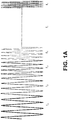
- the exemplary ranging signal employs different frequency components that are contiguous. Other waveforms, including pseudo random, spaced in frequency and/or time or orthogonal, etc. can be also used for as long as the ranging signal bandwidth remains narrow.
- the time duration T f for every frequency component is long enough to obtain the ranging signal narrow-bandwidth property.
- FIG. 2 Another variation of a ranging signal with different frequency components is shown on FIG. 2 . It includes multiple frequencies (f 1 , f 2 , f 3 , f 4 , f n ) transmitted over long period of time to make individual frequencies narrow-band. Such signal is more efficient, but it occupies in a wide bandwidth and a wide bandwidth ranging signal impacts the SNR, which, in turn, reduces the operating range. Also, such wide bandwidth ranging signal will violate FCC requirements on the VHF band or lower frequencies bands. However, in certain applications this wide-bandwidth ranging signal allows an easier integration into existing signal and transmission protocols. Also, such a signal decreases the track-locate time.
- These multiple-frequency (f 1 , f 2 , f 3 , f 4 , f n ) bursts may be also contiguous and/or pseudo random, spaced in frequency and/or time or orthogonal, etc.
- the narrowband ranging mode will produce the accuracy in the form of instantaneous wide band ranging while increasing the range at which this accuracy can be realized, compared to wide band ranging.
- This performance is achieved because at a fixed transmit power, the SNR (in the appropriate signal bandwidths) at the receiver of the narrow band ranging signal is greater than the SNR at the receiver of a wideband ranging signal.
- the SNR gain is on the order of the ratio of the total bandwidth of the wideband ranging signal and the bandwidth of each channel of the narrow band ranging signal. This provides a good trade-off when very rapid ranging is not required, e.g., for stationary and slow-moving targets, such as a person walking or running.
- Master devices and Tag devices are identical and can operate either in Master or Transponder mode. All devices include data/remote control communication channels. The devices can exchange the information and master device(s) can remotely control tag devices.
- multi-path mitigation processor originates the ranging signal to tag(s) and, after a certain delay, the master/reader receives the repeated ranging signal from the tag(s).
- master's multi-path mitigation processor compares the received ranging signal with the one that was originally sent from the master and determines the A ( f n ) estimates in form of an amplitude and a phase for every frequency component f n .
- a ( f n ) is defined for one-way ranging signal trip.
- the ranging signal makes a round-trip. In other words, it travels both ways: from a master/reader to a target/slave and from the target/slave back to the master/reader.
- a complex amplitude determination is based on
- the phase values ⁇ ⁇ RT ( f n ) are obtained by comparing the received by a reader/master returned base-band ranging signal phase and the original (i.e., sent by reader/master) base band ranging signal phase.
- the ranging base band signal is the same as the one depicted in FIG. 1 .
- the ranging base band signal consists of only two frequency components each containing multiple periods of cosine or sine waves of different frequency: F 1 and F 2 .
- the number of periods in a first frequency component is L and the number of periods in a second frequency component is P.
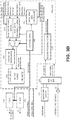
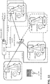
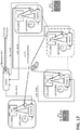
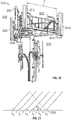
- FIG. 3A , 3B and 3C depict block diagrams of a master or a slave unit (tag) of an RF mobile tracking and locating system.
- F OSC refers to the frequency of the device system clock (crystal oscillator 20 in FIG. 3A ). All frequencies generated within the device are generated from this system clock crystal oscillator.
- M is a master device (unit);
- AM is a tag (target) device (unit).
- the tag device is operating in the transponder mode and is referred to as transponder (AM) unit.
- the device consists of the RF front-end and the RF back-end, base-band and the multi-path mitigation processor.
- the RF back-end, base-band and the multi-path mitigation processor are implemented in the FPGA 150 (see FIGs. 3B and 3C ).
- F OSC M F OSC ⁇ M ;
- F OSC AM F OSC ⁇ AM .
- the base band ranging signal is generated in digital format by the master' FPGA 150, blocks 155 - 180 (see FIG. 2B ). It consists of two frequency components each containing multiple periods of cosine or sine waves of different frequency.
- t 0
- the FPGA 150 in a master device FIG. 3B
- the FPGA 150 starts with F 1 frequency and after time T 1 start generating F 2 frequency for time duration of T 2 .
- the output frequencies TX LO and RX_LO from frequency synthesizer 25 LO signals for mixers 50 and 85
- TX LO and RX_LO from frequency synthesizer 25 can be expressed through constant coefficients.
- These constant coefficients are the same for the master (M) and the transponder (AM) - the difference is in the system crystal oscillator 20 clock frequency of each device.
- the master (M) and the transponder (AM) work in a half-duplex mode.
- Master's RF front-end up-converts the base-band ranging signal, generated by the multi-path mitigation processor, using quadrature up-converter (i.e., mixer) 50 and transmits this up-converted signal.
- quadrature up-converter i.e., mixer
- the master switches from TX to RX mode using RF Front-end TX/RX Switch 15.
- the transponder receives and down-converts the received signal back using its RF Front-end mixer 85 (producing First IF) and ADC 140 (producing Second IF).
- this second IF signal is digitally filtered in the Transponder RF back-end processor using digital filters 190 and further down-converted to the base-band ranging signal using the RF back-end quadrature mixer 200, digital I/Q filters 210 and 230, a digital quadrature oscillator 220 and a summer 270.
- This base-band ranging signal is stored in the transponder's memory 170 using Ram Data Bus Controller 195 and control logic 180.
- the transponder switches from RX to TX mode using RF front-end switch 15 and after certain delay t RTX begins re-transmitting the stored base-band signal.
- the delay is measured in the AM (transponder) system clock.
- t RTX AM t RTX ⁇ AM .
- the master receives the transponder transmission and down-converts the received signal back to the base-band signal using its RF back-end quadrature mixer 200, the digital I and Q filters 210 and 230, the digital quadrature oscillator 220 (see FIG. 3C ).
- the master calculates the phase difference between F 1 and F 2 in the received (i.e., recovered) base-band signal using multi-path mitigation processor arctan block 250 and phase compare block 255.
- the amplitude values are derived from the RF back-end RSSI block 240.
- the multi-path mitigation processor calculates amplitude and phase difference estimates for many time instances over the ranging signal frequency component duration ( T f ). These values, when averaged, improve SNR.
- the SNR improvement can be in an order that is proportional to N , where N is a number of instances when amplitude and phase difference values were taken (i.e., determined).
- Another approach to the SNR improvement is to determine amplitude and phase difference values by applying matching filter techniques over a period of time.
- another approach would be to estimate the phase and the amplitude of the received (i.e., repeated) base band ranging signal frequency components by sampling them and integrating over period T ⁇ T f against the original (i.e., sent by the master/reader) base- band ranging signal frequency components in the I/Q form.
- the integration has the effect of averaging of multiple instances of the amplitude and the phase in the I/Q format. Thereafter, the phase and the amplitude values can be translated from the I/Q format to the
- the transmitter circuitry components 15, 30, 40 and 50 will introduce additional delay, t TX M , that does not depend upon the system clock.
- the RF signal from the master (M) experiences a phase shift ⁇ MULT that is a function of the multi-path phenomena between the master and tag.
- the ⁇ MULT values depend upon the transmitted frequencies, e.g. F 1 and F 2 .
- the transponder (AM) receiver' is not able to resolve each path because of limited (i.e., narrow) bandwidth of the RF portion of the receiver.
- ⁇ ANT AM t ⁇ M ⁇ ⁇ OSC ⁇ K F 1 t ⁇ t DAC M ⁇ t TX M + K SYN _ TX t ⁇ t TX M + ⁇ F 1 MULT + ⁇ DAC M 0 + ⁇ SYN _ TX M 0 , 10 ⁇ 6 ⁇ t ⁇ T 1 ⁇ M + t DAC M + t TX M ;
- ⁇ ANT AM t ⁇ M ⁇ ⁇ OSC ⁇ K F 1 T 1 ⁇ M + K F 2 .
- an output e.g. first IF
- the propagation delay t RX AM in the receiver RF section does not depend upon the system clock.
- the first IF signal is sampled by the RF Back-end ADC 140.
- ADC 140 is under-sampling the input signal (e.g., first IF).
- the ADC also acts like a down-converter producing the second IF.
- the first IF filters, amplifiers and the ADC add propagation delay time.
- ⁇ ADC AM t ⁇ M ⁇ ⁇ OSC ⁇ K F 1 t ⁇ t DAC M ⁇ t TX M ⁇ t RX AM ⁇ t IF _ 1 AM ⁇ t ADC AM + K SYN _ TX t ⁇ t TX M ⁇ t RX AM ⁇ t IF _ 1 AM ⁇ t ADC AM ⁇ ⁇ AM ⁇ ⁇ OSC ⁇ K SYN _ RX _ 1 t ⁇ t IF _ 1 AM ⁇ t ADC AM + K ADC t + ⁇ F 1 MULT + ⁇ SYN _ TX M 0 ⁇ ⁇ SYN _ RX _ 1 AM 0 ⁇ ⁇ ADC _ CLK AM 0 , 10 ⁇ 6 ⁇ t ⁇ T 1 ⁇ M + t DAC M + t TX M + t RX AM + t IF
- the second IF signal (from the ADC output) is filtered by the RF Back-end digital filters 190 and further down-converted back to base-band ranging signal by the third down-converter (i.e., quadrature mixer 200, digital filters 230 and 210 and digital quadrature oscillator 220), summed in the summer 270 and is stored in the memory 170.
- the third down-converter i.e., quadrature mixer 200, digital filters 230 and 210 and digital quadrature oscillator 220
- ⁇ BB AM t ⁇ M ⁇ ⁇ OSC ⁇ K F 1 t ⁇ t DAC M ⁇ t TX M ⁇ t RX AM + t IF _ 1 AM + t ADC AM ⁇ t FIR ⁇ AM + K SYN _ TX t ⁇ t TX M ⁇ t RX AM ⁇ t IF _ 1 AM ⁇ t ADC AM ⁇ t FIR ⁇ AM ⁇ ⁇ AM ⁇ ⁇ OSC ⁇ K SYN _ RX _ 1 t ⁇ t IF _ 1 AM ⁇ t ADC AM ⁇ t FIR ⁇ AM + K ADC t ⁇ t FIR ⁇ AM + K SYN _ RX _ 2 t + ⁇ F 1 MULT + ⁇ SYN _ TX M 0 ⁇ ⁇ SYN _ RX
- ⁇ BB AM t ⁇ M ⁇ ⁇ OSC ⁇ K F 1 T 1 ⁇ M + K F 2 t ⁇ T 1 ⁇ M ⁇ t DAC M ⁇ t TX M ⁇ t RX AM ⁇ t IF _ 1 AM ⁇ t ADC AM ⁇ t FIR ⁇ AM + K SYN _ TX t ⁇ t TX M ⁇ t RX AM ⁇ t IF _ 1 AM ⁇ t ADC AM ⁇ t FIR ⁇ AM ⁇ ⁇ AM ⁇ ⁇ OSC ⁇ K SYN _ RX _ 1 t ⁇ t IF _ 1 AM ⁇ t ADC AM ⁇ t FIR ⁇ AM + K ADC t ⁇ t FIR ⁇ AM + K SYN _ RX _ 2 t + ⁇ F 2 MULT + ⁇ SYN _ TX M 0 ⁇ ⁇ SYN _ RX _ 1 AM
- RX->TX delay t RTX AM t RTX ⁇ AM .
- RF AM t ⁇ M ⁇ ⁇ OSC ⁇ K F 1 t ⁇ t DAC M ⁇ t TX M ⁇ t RX AM ⁇ t IF _ 1 AM ⁇ t ADC AM ⁇ t FIR ⁇ AM ⁇ t RTX ⁇ AM ⁇ t DAC AM ⁇ t TX AM + K SYN _ TX t ⁇ t TX M ⁇ t RX AM ⁇ t IF _ 1 AM ⁇ t ADC AM ⁇ t FIR ⁇ AM ⁇ t RTX ⁇ AM ⁇ t DAC AM ⁇ t TX AM ⁇ ⁇ AM ⁇ t IF _ 1 AM ⁇ t ADC AM ⁇ t FIR ⁇ AM ⁇ t RTX ⁇ AM ⁇ t DAC AM ⁇ t TX AM ⁇ ⁇ AM ⁇ OS
- ⁇ ANT M t ⁇ M ⁇ ⁇ OSC ⁇ K F 1 t ⁇ t DAC M ⁇ t TX M ⁇ t RX AM ⁇ t IF _ 1 AM ⁇ t ADC AM ⁇ t FIR ⁇ AM ⁇ t RTX ⁇ AM ⁇ t DAC AM ⁇ t TX AM + K SYN _ TX t ⁇ t TX M ⁇ t RX AM ⁇ t IF _ 1 AM ⁇ t ADC AM ⁇ t FIR ⁇ AM ⁇ t RTX ⁇ AM ⁇ t DAC AM ⁇ t TX AM ⁇ IF _ 1 AM ⁇ t ADC AM ⁇ t FIR ⁇ AM ⁇ t RTX ⁇ AM ⁇ t DAC AM ⁇ t TX AM ⁇
- ⁇ BB _ RECOV M t ⁇ M ⁇ ⁇ OSC ⁇ K F 1 T 1 ⁇ M + K F 2 t ⁇ T 1 ⁇ M ⁇ t DAC M ⁇ t TX M ⁇ t RX AM ⁇ t IF _ 1 AM ⁇ t ADC AM ⁇ t FIR ⁇ AM ⁇ t RTX ⁇ AM ⁇ t DAC AM ⁇ t TX AM ⁇ t RX M ⁇ t IF _ 1 M ⁇ t ADC M ⁇ t FIR ⁇ M + K SYN _ TX t ⁇ t TX M ⁇ t RX AM ⁇ t IF _ 1 AM ⁇ t ADC AM ⁇ t FIR ⁇ AM ⁇ t RTX ⁇ AM ⁇ t DAC AM ⁇ t RX AM ⁇ t IF _ 1 M ⁇ t ADC AM ⁇ t FIR ⁇ AM ⁇ t
- T D _ M ⁇ AM t DAC M + t TX M + t RX AM + t IF _ 1 AM + t ADC AM + t FIR ⁇ AM + t RTX ⁇ AM + t DAC AM + t TX AM + t RX M + t IF _ 1 M + t ADC M + t FIR ⁇ M ;
- T D _ M - AM is the propagation delay through master (M) and transponder (AM) circuitry.
- ⁇ BB _ RECOV M t ⁇ M ⁇ ⁇ OSC ⁇ K F 1 t ⁇ T D _ M ⁇ AM + 2 ⁇ ⁇ F 1 MULT + ⁇ BB _ M ⁇ AMN 0 + ⁇ , 2 ⁇ 10 ⁇ 6 ⁇ t ⁇ T 1 ⁇ M + T D _ M ⁇ AM ;
- ⁇ BB _ RECOV M t ⁇ M ⁇ ⁇ OSC ⁇ K F 1 T 1 ⁇ M + K F 2 t ⁇ T 1 ⁇ M ⁇ T D _ M ⁇ AM + 2 ⁇ ⁇ F 2 MULT + ⁇ BB _ M ⁇ AM 0 + ⁇ , t > T 1 ⁇ M + T D _ M ⁇ AM + 2 ⁇ 10 ⁇ 6
- T D _ M ⁇ AM T LB _ M ⁇ M + T LB _ AM ⁇ AM + t RTX ⁇ AM ;
- T LB _ M t DAC M + t TX M + t RX M + t IF _ 1 M + t ADC M + t FIR ⁇ M ;
- T LB _ AM t DAC AM + t TX AM t RX AM + t IF _ 1 AM + t ADC AM + t FIR ⁇ AM
- T LB_M and T LB_AM are propagation delays through the master (M) and transponder (AM) TX and RX circuitries that are measured by placing devices in the loop-back mode. Note that the master and the transponder devices can measure T LB_M and T LB_AM automatically; and we also know the t RTX value.
- the initial phase value 2 ⁇ ⁇ F 1 MULT can be assumed to be equal zero because the subspace algorithms are not sensitive to a constant phase offset. If necessary, the 2 ⁇ ⁇ F 1 MULT value (phase initial value) can be found by determining the TOA (Time Of Arrival) using the narrow-bandwidth ranging signal method as described in related U.S. Patent No. 7,561,048 .
- the returned base-band ranging signal phase values ⁇ BB _ RECOV M t are calculated by the multi-path processor's arctan block 250.
- the recovered (i.e., received) base-band ranging signal has the same frequency as the original base-band signal that was sent by the master.
- the master (M) and the transponder (AM) system clocks can differ.
- the base-band signal consists of several frequency components, each component is consists of multiple periods of a sinusoid, it is also possible to estimate the phase and the amplitude of the received ranging signal by sampling the received base-band signal individual component frequency with the corresponding original (i.e., sent by the master) base-band signal individual frequency component and integrating the resulting signal over period T ⁇ T f .
- This operation generates complex amplitude values ⁇ RT ( f n ) of received ranging signal in the I/Q format.
- each base-band signal individual frequency component that was sent by the master has to be shifted in time by the T D _ M - AM .
- the integration operation produces effect of averaging out the multiple instances of the amplitude and the phase (e.g., increasing the SNR).
- the phase and the amplitude values can be translated from the I/Q format to the
- and ⁇ ⁇ ( f n ) format can be implemented in the phase compare block 255 in FIG. 3C .
- either the method of the preferred embodiment, based on the equation (5), or an alternative method, described in this section, can be used.
- the ranging signal bandwidth is narrow, the frequency difference f n - f 1 can be relatively large, for example, in an order of several megahertz. As a result, the receiver's bandwidth has to be kept wide enough to pass all of the f 1 : f n ranging signal frequencies components. This wide receiver bandwidth impacts the SNR.
- the received ranging signal base-band frequency components can be filtered by the RF back-end processor in FPGA 150 by the digital narrow bandwidth filters tuned for each individual frequency component of the received base-band ranging signal.
- this large number of digital filters puts additional burden on the FPGA resources, increasing its cost, size and power consumption.
- ranging signal is sent by the master. Each instance consists of only two frequencies: f 1 : f 2 ; f 1 : f 3 ⁇ ; f 1 : f i ⁇ ; f 1 : f n . Similar strategies are also possible.
- LO signals for up-converters and down-converters mixers are generated using the Direct Digital Synthesis (DDS) technology.
- DDS Direct Digital Synthesis
- Analog frequency synthesizers can also be used, but may take additional time to settle after frequency is changed. Also, in case of analog synthesizers, two measurements at the same frequency would have to be made in order to cancel a phase offset that might develop after changing the analog synthesizer's frequency.
- T D _ M - AM The actual T D _ M - AM that is used in the above equations is measured in both: the master (M) and the transponder (AM) systems clocks, e.g. T LB_AM and t RTX are counted in the transponder (AM) clocks and T LB_M is counted in the master (M) clock.
- T LB_AM and t RTX are measured (counted) in master (M) clock.
- the master and the transponder units are capable of synchronizing clocks with any of the devices.
- a master device can serve as a reference.
- Clock synchronization is accomplished by using the remote control communication channel, whereby under FPGA 150 control, the frequency of temperature compensated crystal oscillator TCXO 20 is adjusted. The frequency difference is measured at the output of the summer 270 of the master device while the selected transponder device is transmitting a carrier signal.
- the master sends a command to the transponder to increase/decrease TCXO frequency.
- This procedure may be repeated several times to achieve greater accuracy by minimizing frequency at the summer 270 output. Please note that in an ideal case the frequency at the summer 270 output should become equal to zero.
- An alternative method is to measure the frequency difference and make a correction of the estimated phase without adjusting the transponder' TCXO frequency.
- TCXO components have high degree of accuracy and stability. Specifically, TCXO components for the GPS commercial applications are very accurate. With these devices, the phase error impact on locating accuracy can be less than one meter without the need for frequent clock synchronization.
- narrow bandwidth ranging signal multi-path mitigation processor After narrow bandwidth ranging signal multi-path mitigation processor obtains the returned narrow bandwidth ranging signal complex amplitude ⁇ RT ( f n ), the further processing (i.e., execution of super-resolution algorithms), is implemented in the software-based component, which is a part of the multi-path mitigation processor.
- This software component can be implemented in the master (reader) host computer CPU and/or the microprocessor that is embedded in the FPGA 150 (not shown).
- the multi-path mitigation algorithm(s) software component is executed by the master host computer CPU.
- the super-resolution algorithm(s) produce estimation of (2 ⁇ ⁇ ⁇ K ) "frequencies", e.g. ⁇ K values.
- the multi-path mitigation processor selects ⁇ with the smallest value (i.e., the DLOS delay time).
- the DLOS path can be separated from MP paths by employing a continuous (in time) chirp.
- this continuous chirp is Linear Frequency Modulation (LFM).
- LFM Linear Frequency Modulation
- other chirp waveforms can be also used.
- each received single chirp is aligned so that the returned chirp is from the middle of the area of interest.
- ⁇ 0 is the initial frequency for 0 ⁇ t ⁇ T.
- the returned signal (cirp) is s ( t - ⁇ ).
- the multi-path mitigation processor then "deramps" the s ( t - ⁇ ) by performing complex conjugate mix with the originally transmitted chirp.
- the multi-path mitigation processor produces ⁇ N complex amplitude samples in time domain that are used in further processing (i.e., execution of super-resolution algorithms).
- This further processing is implemented in the software component, which is a part of the multi-path mitigation processor.
- This software component can be executed by the master (reader) host computer CPU and/or by the microprocessor that is embedded in the FPGA 150 (not shown), or both.
- the multi-path mitigation algorithm(s) software is executed by the master host computer CPU.
- the super-resolution algorithm(s) produce estimation of 2 ⁇ k "frequencies", e.g. ⁇ K values.
- the multi-path mitigation processor selects ⁇ with the smallest value, i.e. the DLOS delay time.
- Threshold technique a special processing method, called the "threshold technique,” which can serve as an alternative to the super-resolution algorithms. In other words, it is used to enhance reliability and accuracy in distinguishing DLOS path from other MP paths using the artificially generated synthetic wider bandwidth ranging signal.
- the basic idea of the thresholded method that is used in the preferred embodiment is to enhance the artificially generated synthetic wider bandwidth ranging reliability and accuracy in distinguishing DLOS path from other MP paths.
- the threshold method detects when the start of the leading edge of a wideband pulse arrives at a receiver. Because of filtering in the transmitter and receiver, the leading edge does not rise instantaneously, but rises out of the noise with smoothly increasing slope.
- the TOA of the leading edge is measured by detecting when the leading edge crosses a predetermined threshold T.
- a small threshold is desirable because it gets crossed sooner and the error delay ⁇ between the true start of the pulse and the threshold crossing is small.
- any pulse replica arriving due to multi-path has no effect if the start of the replica having a delay greater than ⁇ .
- the presence of noise places a limit on how small the threshold T can be.
- One way to decrease the delay ⁇ is to use the derivative of the received pulse instead of the pulse itself, because the derivative rises faster.
- the second derivative has an even faster rise. Higher order derivatives might be used, but in practice they can raise the noise level to an unacceptable value, so the thresholded second derivative is used.
- the 2.75 MHz wide signal depicted in FIG. 4 has a fairly wide bandwidth, it is not suitable for measuring range by the abovementioned method. That method requires transmitted pulses each having a zero-signal precursor. However, it is possible to achieve that goal by modifying the signal so that the sinusoidal waveform between the pulses is essentially cancelled out. In the preferred embodiment it is done by constructing a waveform which closely approximates the signal on a chosen interval between the tall pulses, and then subtracting it from the original signal.
- the technique can be illustrated by applying it to the signal in FIG. 1 .
- the two black dots shown on the waveform are the endpoints of an interval I centered between the first two pulses.
- the length of the cancelled portion of s ( t ) is about 3.7 microseconds or 1,110 meters. This is more than enough to eliminate any residual signal from previous non-zero portions of r ( t ) due to the multi-path.
- the main peak has value of approximately 35, and the largest magnitude in the precursor (i.e., cancellation) region is about 0.02, which is 65 dB below the main peak. This is desirable for getting good performance using the TOA measurement thresholded technique as described above.
- the period of the signal is only 2/ ⁇ f ⁇ 2.35 microseconds as compared to the signal in FIG. 5 , where the period is 8 microseconds. Since this example has more periods per unit time, one might expect that more processing gain could be achieved.
- the amplitude of the main peak is about 1/3 as large as before, which tends to cancel the expected extra processing gain.
- the length of the zero-signal precursor segments is shorter, about 0.8 microseconds or 240 meters. This should still be enough to eliminate any residual signal from previous non-zero portions of r ( t ) due to the multi-path.
- the largest magnitude in the precursor (i.e., cancellation) region is now about 75 dB below the main peak, a 10 dB improvement from the previous example.
- r ( t ) Transmission at RF Frequencies: up to this point r ( t ) has been described as a base-band signal for purposes of simplicity. However, it can be translated up to RF, transmitted, received, and then reconstituted as a base-band signal at the receiver.
- the parameter b k is the k th coefficient in expression (21) for r ( t ).
- the parameters ⁇ j and ⁇ j are respectively the path delay and phase shift (due to dielectric properties of a reflector) of the j th propagation path.
- the parameter ⁇ is the phase shift occurring in the down-conversion to base-band in the receiver.
- Sequential Carrier Transmissions and Signal Reconstruction are illustrated in FIG. 1 and FIG 1A . It is assumed that the transmitter and the receiver are time and frequency synchronized, the 2N + 3 transmitted carriers need not be transmitted simultaneously. As an example, consider the transmission of the signal whose base-band representation is that of FIG. 1A and FIG. 6 .
- the entire process of receiving 9 frequency components can be repeated in 9-millisecond blocks of additional reception to increase the processing gain. In one second of total reception time there would be about 111 such 9-millisecond blocks available for processing gain. Additionally, within each block there would be additional processing gain available from 0.009/(2/ ⁇ f ) ⁇ 383 main peaks.
- This method is not restricted to 1-millisecond transmissions, and the length of the transmissions may be increased or decreased. However, the total time for all transmissions should be short enough to freeze any motion of the receiver or transmitter.
- the coefficients b k in the equation (21) are used for construction of r ( t ) at the transmitter and may be introduced at the receiver instead. This is easily seen by considering the sequence of signals in the equation (20) in which the final signal is the same if b k is introduced at the last step instead of at the beginning.
- the values are as follows: cos ⁇ k t at baseband in transmitter cos ⁇ + ⁇ k t translated by frequency ⁇ up to RF a j cos ⁇ + ⁇ k t ⁇ ⁇ j + ⁇ j at receiver antenna a j cos ⁇ k t ⁇ ⁇ j + ⁇ j + ⁇ translated by frequency ⁇ ⁇ to baseband a j b k cos ⁇ k t ⁇ ⁇ j + ⁇ j + ⁇ weighted by coefficient b k at baseband
- the transmitter can then transmit all frequencies with the same amplitude, which simplifies its design. It should be noted, that this method also weights the noise at each frequency, the effect of which should be considered. It should also be noted that coefficient weighting should be done at the receiver in order to effect the polarity reversal of g ( t ) to get twice as many useable main peaks.
- both: the Master Unit and the Tag Unit also perform voice, data and control communication functions.
- both the Master Unit and the Tag perform voice, data and control communication functions in addition to the distance measurement function.
- the ranging signal(s) are subject to the extensive sophisticated signal processing techniques, including the multi-path mitigation.
- these techniques may not lend themselves to the voice, data and control signals.
- the operating range of the proposed system (as well as other existing systems) may be limited not by its ability to measure distance reliably and accurately, but by being out of range during voice and/or data and/or control communications.
- Radio Frequency (RF)-based identification, tracking and locating systems the distance measurement functionality is separated from the voice, data and control communication functionality.
- RF Transceivers are used to perform voice, data and control communication functions.
- the drawback of this approach is system increased cost, complexity, size, etc.
- a narrow bandwidth ranging signal or base-band narrow bandwidth ranging signal several individual frequency components are modulated with the identical data/control signals and in case of voice with digitized voice packets data.
- the individual frequency components that have the highest signal strength are demodulated and the obtained information reliability may be further enhanced by performing "voting" or other signal processing techniques that utilize the information redundancy.
- This method allows to avoid the "null" phenomena, wherein the incoming RF signals from multiple paths are destructively combining with the DLOS path and each other, thus significantly reducing the received signal strength and associated with it SNR. Moreover, such method allows to find a set of frequencies at which the incoming signals from multiple paths are constructively combining with DLOS path and each other, thus increasing the received signal strength and associated with it SNR.
- All spectrum estimation-based super-resolution algorithms work by splitting the incoming signal complex amplitude data into two sub-spaces: the noise sub-space and signals sub-space. If these sub-spaces are properly defined (separated), then the model size is equal to the signal sub-space size (dimension).
- the model size estimation is accomplished using an "F” statistic.
- F the singular value decomposition of the estimate of the covariance matrix (with forward/backward correlation smoothing) is ordered in ascending order. Thereafter, a division is made whereby the (n+1) eigenvalue is divided by the n-th eigenvalue. This ratio is an "F” random variable. The worst case is an "F” random variable of (1,1) degree of freedom. The 95% confidence interval for a "F” random variable with (1,1) degrees of freedom is 161. Setting that value as a threshold determines the model size. Note also that for the noise subspace, the eigenvalues represent an estimate of the noise power.
- model size the number of signals, i.e., the model size. Since model size underestimation reduces the frequency estimation accuracy, it is prudent to increase the model size by adding a certain number. This number can be determined experimentally and/or from simulations. However, when signals are not closely spaced, the model size will be overestimated.
- spurious i.e., non-existent, frequencies may appear.
- using signal amplitude for spurious signals detection does not always work because in some cases a spurious signal(s) was observed to have amplitude that is very close to actual signal(s) amplitude. Therefore, in addition to the amplitude discrimination, filters can be implemented to improve spurious frequencies elimination probability.
- the frequencies that are estimated by super-resolution algorithms are artificial frequencies (equation 2). In fact, these frequencies are individual paths delays of the multipath environment. As a result, there should be no negative frequencies and all negative frequencies that are produced by a super-resolution algorithm are spurious frequencies to be rejected.
- a DLOS distance range can be estimated from the complex amplitude ⁇ ( f n ) values obtained during measurements using methods that are different from super-resolution methods. While these methods have lower accuracy, this approach establishes range that is used to discriminate delays, i.e., frequencies. For example, he ratio of ⁇ ⁇ ⁇ 2 ⁇ ⁇ f 2 ⁇ ⁇ f in ⁇ f intervals where the signal amplitude
- the ranging signal makes a round-trip. In other words, it travels both ways: from a master/reader to a target/slave and from the target/slave back to the master/reader:
- ⁇ is an operating frequency in the operating band and ⁇ is the tone signal amplitude.
- N is number of signal paths in the multipath environment; K0 and ⁇ 0 are amplitude and time-of-flight of the DLOS signal;
- 1, K 0 > 0,
- S one ⁇ way t ⁇ ⁇ e ⁇ j ⁇ t ⁇ A ⁇ ⁇ e ⁇ j ⁇ ⁇
- S retransmit t ⁇ ⁇ e ⁇ j ⁇ t ⁇ A ⁇ ⁇ e ⁇ j ⁇ ⁇
- are directly obtainable from target/slave device.
- the ranging signal different frequency components are close to each other, then for most part the one-way phase can be found by dividing the roundtrip phase by two. Exceptions will include the areas that are close to the "null", where the phase can undergo a significant change even with small frequency step. Note: the "null” phenomena is where the incoming RF signals from multiple paths are destructively combining with the DLOS path and each other, thus significantly reducing the received signal strength and associated with it SNR.
- h ( t ) be the one-way impulse response of a communications channel.
- H ( ⁇ ) A ( ⁇ ) e j ⁇ ( ⁇ ) be a one-way transfer function and let I be an open interval of frequencies ⁇ containing no zeros of H ( ⁇ ). Then the phase function ⁇ ( ⁇ ) of H ( ⁇ ) must be continuous on I .
- ⁇ 0 be a frequency in the interval I .
- H ( ⁇ 0 ) has been plotted as a point in the complex plane, and by hypothesis, H ( ⁇ 0 ) ⁇ 0.
- ⁇ > 0 be an arbitrarily small real number, and consider the two angles of measure ⁇ shown in the FIG. 7 , as well as the circle centered at H ( ⁇ 0 ) and tangent to the two rays OA and OB.
- H ( ⁇ ) is continuous for all ⁇ .
- H ( ⁇ ) be a one-way function that generates G ( ⁇ ) on the interval ( ⁇ 1 , ⁇ 2 ), and assume that G ( ⁇ ) has at least one zero on ( ⁇ 1 , ⁇ 2 ). The zeros of G ( ⁇ ) will separate ( ⁇ 1 , ⁇ 2 ) into a finite number of abutting open frequency intervals J 1 , J 2 ,..., J n . On each such interval the solution H ( ⁇ ) or - H ( ⁇ ) will be found using either Theorem 1 or Theorem 3.
- the limit of the n th derivative of our one-way solution in J 1 as ⁇ ⁇ ⁇ 1 from the left will be either H ( n ) ( ⁇ 1 ) or -H ( n ) ( ⁇ 1 ) according to whether our solution in J 1 is H ( ⁇ ) or -H( ⁇ ) .
- the limit of the n th derivative of our one-way solution in J 2 as ⁇ ⁇ ⁇ 1 from the right will be either H ( n) ( ⁇ 1 ) or -H ( n ) ( ⁇ 1 ) according to whether our solution in J 2 is H ( ⁇ ) or -H ( ⁇ ) .
- the two-way transfer function G ( ⁇ ) will be measured at discrete frequencies, which must be close enough together to enable reasonably accurate computation of derivatives near the zeros of G ( ⁇ ) .
- this multipath model will become harmonic signals spectrum in which the propagation delay of the path is transformed to a harmonic signal.
- the super (high) resolution spectral estimation methods are designed to distinguish closely-placed frequencies in the spectrum and used for estimating the individual frequencies of multiple harmonic signals, e.g., paths delays. As a result, path delays can be accurately estimated.
- the super resolution spectral estimation makes use of the eigen-structure of the covariance matrix of the baseband ranging signal samples and covariance matrix intrinsic properties to provide a solution to an underlying estimation of individual frequencies, e.g. paths delays.
- One of the eigen-structure properties is that the eigenvalues can be combined and consequently divided into orthogonal noise and signal eigenvectors, aka subspaces.
- Another eigen-structure property is the rotation-invariant signal subspaces property.
- the subspace decomposition technology (MUSIC, rootMUSIC, ESPRIT, etc.) relies on breaking the estimated covariance matrix of the observed data into two orthogonal subspaces, the noise subspace and the signal subspace.
- the theory behind the subspace decomposition methodology is that the projection of the observable onto the noise subspace consists of only the noise and the projection of the observable onto the signal subspace consists of only the signal.
- the spectral estimation methods assume that signals are narrow-band, and the number of harmonic signals is also known, i.e., the size of the signal subspace needs to be known.
- the size of the signal subspace is called as the model size.
- it cannot be known in any detail and can change rapidly - particularly indoors - as the environment changes.
- One of the most difficult and subtle issues when applying any subspace decomposition algorithm is the dimension of the signal subspace that can be taken as the number of frequency components present, and which is the number multipath reflections plus the direct path. Because of real-world measurement imperfections there always will be an error in the model size estimation, which in turn will result in loss of accuracy of frequencies estimation, i.e., distances.
- one embodiment includes six features that advance the state of the art in the methodology of subspace decomposition high resolution estimation. Included is combining two or more algorithms estimating individual frequencies by using different eigen-structure properties that further reduces the delay path determination ambiguity.
- Root Music finds the individual frequencies, that when the observable is projected onto the noise subspace, minimizes the energy of the projection.
- the Esprit algorithm determines the individual frequencies from the rotation operator. And in many respects this operation is the conjugate of Music in that it finds the frequencies that, when the observable is projected onto the signal subspace, maximizes the energy of the projection.
- the model size is the key to both of these algorithms, and in practice, in a complex signal environment such as seen in indoor ranging - the model size which provides the best performance for Music and Esprit are in general not equal, for reasons that will be discussed below.
- the first feature of the embodiment is the use of the F-statistic to estimate the model size (see above).
- the second feature is the use of different Type I Error probabilities in the F-statistic for Music and Esprit. This implements the Type I Error differences between Music and Esprit as discussed above.
- the third feature is the use of a base model size and a window in order to maximize the probability of detecting the direct path.
- the fourth feature of the embodiment is the use of multiple measurements.
- the probability distribution of the multiple answers resulting from multiple measurements, each using multiple model sizes from both a Music and Esprit implementation, will be multimodal. Conventional cluster analysis will not be sufficient for this application.
- the fifth feature is the development of multimodal cluster analysis to estimate the direct range and equivalent range of the reflected multipath components.
- the sixth feature is the analysis of the statistics of the range estimates provided by the cluster analysis (range and standard deviation and combing those estimates that are statistically identical. This results in a more accurate range estimate.
- the abovementioned methods can be also used in wide bandwidth ranging signal location-finding systems.
- the present embodiments relate to a positioning/locating method in wireless communication and other wireless networks that substantially obviate one or more of the disadvantages of the related art.
- the present embodiments advantageously improve the accuracy of tracking and locating functionality in multiple types of wireless network by utilizing multi-path mitigation processes, techniques and algorithms, described in related U.S. Patent No. 7,872,583 ,
- These wireless networks include Wireless Personal Area Networks (WPGAN) such as ZigBee and Blue Tooth, wireless local area network (WLAN) such as WiFi and UWB, Wireless Metropolitan Area Networks, (WMAN) typically consisting of multiple WLANs, WiMax being the primary example, wireless Wide Area Networks (WAN) such as White Space TV Bands, and Mobile Devices Networks (MDN) that are typically used to transmit voice and data.
- WPGAN Wireless Personal Area Networks
- WLAN wireless local area network
- WMAN Wireless Metropolitan Area Networks
- WiMax wireless Wide Area Networks
- WAN Wide Area Networks
- MDN Mobile Devices Networks
- MDNs are typically based on Global System for Mobile Communications (GSM) and Personal Communications Service (PCS) standards.
- GSM Global System for Mobile Communications
- PCS Personal Communications Service
- LTE Long Term Evolution
- These wireless networks are typically comprised of a combination of devices, including base stations, desktop, tablet and laptop computers, handsets, smartphones, actuators, dedicated tags, sensors as well as other communication and data devices (generally, all these devices are referred to as “wireless network devices").
- Existing location and positioning information solutions use multiple technologies and networks, including GPS, AGPS, Cell Phone Tower Triangulation, and Wi-Fi. Some of the methods used to derive this location information include RF Fingerprinting, RSSI, and TDOA. Although acceptable for the current E911 requirements, existing location and ranging methods do not have the reliability and accuracy required to support the upcoming E911 requirements as well as LBS and/or RTLS applications requirements, especially indoors and urban environments.
- the methods described in related U.S. Patent No. 7,872,583 significantly improve the ability to accurately locate and track targeted devices within a single wireless network or a combination of multiple wireless networks.
- the embodiment is a significant improvement to the existing implementation of tracking and location methods used by wireless networks that use Enhanced Cell-ID and OTDOA (Observed Time Difference of Arrival), including DL-OTDOA (Downlink OTDOA), U-TDOA, UL-TDOA and others
- the Enhanced Cell ID technique allows estimating the position of the user (UE- User Equipment) with the accuracy of the particular sector coverage area. Thus, the attainable accuracy depends on the cell (base station) sectoring scheme and antenna beam-width.
- the Enhanced Cell ID technique adds RTT (Round Trip Time) measurements from the eNB.
- the RTT constitutes the difference between transmission of a downlink DPCH - Dedicated Physical Channel, (DPDCH)/DPCCH: Dedicated Physical Data Channel/Dedicated Physical Control Channel) frame and the beginning of a corresponding uplink physical frame.
- DPDCH Downlink DPCH - Dedicated Physical Channel
- DPCCH Dedicated Physical Data Channel/Dedicated Physical Control Channel
- the time of arrival of the signal coming from neighboring base stations is calculated.
- the UE position can be estimated in the handset (UE-based method) or in the network (NT-based, UE-assisted method) once the signals from three base stations are received.
- the measured signal is the CPICH (Common Pilot Channel).
- the propagation time of signals is correlated with a locally generated replica. The peak of correlation indicates the observed time of propagation of the measured signal.
- Time difference of arrival values between two base stations determines a hyperbola. At least three reference points are needed to define two hyperbolas. The location of the UE is in the intersection of these two hyperbolas (see Figure 11 ).
- Idle Period Downlink is further OTDOA enhancement.
- the OTDOA-IPDL technique is based on the same measurements as the regular OTDOA Time measurements are taken during idle periods, in which serving eNB ceases its transmissions and allows the UE within the coverage of this cell to hear pilots coming from distant eNB(s).
- Serving eNB provides idle periods in continuous or burst mode. In the continuous mode, one idle period is inserted in every downlink physical frame (10 ms). In the burst mode, idle periods occur in a pseudorandom way. Further improvement is obtained via Time Aligned IPDL (TA-IPDL). Time alignment creates a common idle period, during which, each base station will either cease its transmission or transmit the common pilot. The pilot signal measurements will occur in idle period.
- TA-IPDL Time Aligned IPDL
- Time alignment creates a common idle period, during which, each base station will either cease its transmission or transmit the common pilot.
- the pilot signal measurements will occur in idle period.
- One Multi-path mitigation technique uses detections/measurements from excess number of eNB(s) or Radio Base Stations (RBS). The minimum is three, but for multipath mitigation the number of RBS's required is at least six to eight (see METHOD AND ARRANGEMENT FOR DL-OTDOA (DOWNLINK OBSERVED TIME DIFFERENCE OF ARRIVAL) POSITIONING IN A LTE (LONG TERM EVOLUTION) WIRELESS COMMUNICATIONS SYSTEM, WO/2010/104436 ). However, the probability of an UE hearing from this large number of eNB(s) is much lower than from three eNB(s). This is because with large number of RBS (eNBs) there will be several ones that are far away from the UE and the received signal from these RBS (es) may fall below the UE receiver sensitivity level or the received signal will have low SNR.
- RBS Radio Base Stations
- RF reflections e.g., multi-path
- DLOS Direct Line of Site
- CPICH, uplink DPCCH/DPDCH and other signals that are used in various CELL ID and OTDOA methods/techniques, including the RTT measurements are of a limited bandwidth the DLOS signal and reflected signals cannot be differentiated without proper multi-path processing/mitigation; and without this multi-path processing these reflected signals will induce an error in the estimated time difference of arrival (TDOA) and time of arrival (TOA) measurements, including RTT measurements.
- TDOA estimated time difference of arrival
- TOA time of arrival
- 3 G TS 25.515 v.3.0.0 (199-10) standards define the RTT as ".... the difference between transmission of a downlink DPCH frame (signal) and the reception of the beginning (first significant path) of the corresponding uplink DPCCH/DPDCH frame (signal) from UE".
- the standard does not define what constitutes this "first significant path”.
- the standard goes on noting that "The definition of the first significant path needs further elaboration”. For example, in heavy multipath environment it is a common occurrence whereby the DLOS signal, which is the first significant path , is severely attenuated (10 dB - 20 dB) relatively to one or more reflected signal(s). If the "first significant path” is determined by measuring the signal strength, it may be one of the reflected signal(s) and not the DLOS signal. This will result in erroneous TOA/DTOA/RTT measurement(s) and loss of locating accuracy.
- the locating accuracy was also impacted by the low sampling rate of frames (signals) that are used by the locate methods - RTT, CPCIH and other signals.
- the current third and following wireless network generations have much higher sampling rate.
- the locating accuracy real impact is from the terrestrial RF propagation phenomena (multipath).
- the embodiment can be used in all wireless networks that employ reference and/or pilot signals, and/ or synchronization signals, including simplex, half-duplex and full duplex modes of operation.
- the embodiment operates with wireless networks that employ OFDM modulation and/or its derivatives.
- the embodiment operates with LTE networks.
- wireless networks including WiMax, WiFi, and White Space.
- Other wireless networks that do not use reference and/or pilot or synchronization signals may employ one or more of the following types of alternate modulation embodiments as described in related U.S. Patent No. 7,872,583 : 1) where a portion of frame is dedicated to the ranging signal/ranging signal elements as described in related U.S. Patent No. 7,872,583 ; 2) where the ranging signal elements (related U.S. Patent No. 7,872,583 ) are embedded into transmit/receive signals frame(s); and 3) where the ranging signal elements (described in related U.S. Patent No. 7,872,583 ) are embedded with the data.
- a smart phone can have Blue Tooth, WiFi, GSM and LTE functionality with the capability of operating on multiple networks at the same time.
- different wireless networks can be utilized to provide positioning/locating information.
- the proposed embodiment method and system leverages the wireless network reference/pilot and/ or synchronization signals. Furthermore, the reference/pilot signal/ synchronization signals measurements might be combined with RTT (Round Trip Time) measurements or system timing.
- RF-based tracking and locating is implemented on 3GPP LTE cellular networks, but could be also implemented on other wireless networks, for example WiMax, Wi-Fi, LTE, sensors networks, etc. that employ a variety of signaling techniques.
- WiMax Wireless Fidelity
- Wi-Fi Wireless Fidelity
- LTE Long Term Evolution
- sensors networks etc.
- Both the exemplary and mentioned above alternative embodiments employ multi-path mitigation method/techniques and algorithms that are described in related U.S. Patent No. 7,872,583 .
- the proposed system can use software implemented digital signal processing.
- the system of the embodiment leverages User Equipment (UE), e.g. cell phone or smart phone, hardware/software as well as Base Station (Node B)/enhanced Base Station (eNB) hardware/software.
- UE User Equipment
- Node B Base Station
- eNB Enhanced Base Station
- a base station generally consists of transmitters and receivers in a cabin or cabinet connected to antennas by feeders. These base stations include, Micro Cell, Pico Cell, Macro Cell, Umbrella Cell, Cell Phone towers, Routers and Femtocells.
- UE User Equipment
- Node B Base Station
- eNB Enhanced Base Station
- the improved accuracy comes from the multipath mitigation that is provided by the present embodiments and the related U.S. Patent No. 7,872,583 .
- the embodiments use multi-path mitigation algorithms, network reference/ pilot and/ or synchronization signals and network node (eNB). These might be supplemented with RTT (Round Time Trip) measurements.
- the multi-path mitigation algorithms are implemented in UE and/or base station (eNB), or both: UE and eNB
- the embodiments advantageously use the multi-path mitigation processor/algorithms (see related U.S. Patent No. 7,872,583 ) that allow separating the DLOS signal and reflected signals, even when DLOS signal is significantly attenuated (10 dB - 20 dB lower) relatively to one or more reflected signals.
- the embodiments significantly lower the error in the estimated ranging signal DLOS time-of-flight and consequently TOA, RTT and DTOA measurements.
- the proposed multi-path mitigation and DLOS differentiating (recognizing) method can be used on all RF bands and wireless systems/networks. And it can support various modulation/demodulation techniques, including Spread Spectrum techniques, such as DSS (Direct Spread Spectrum) and FH (Frequency Hopping).
- noise reduction methods can be applied in order to further improve the method's accuracy.
- These noise reduction methods can include, but are not limited to, coherent summing, non-coherent summing, Matched filtering, temporal diversity techniques, etc.
- the remnants of the multi-path interference error can be further reduced by applying the post-processing techniques, such as, maximum likelihood estimation (e.g., Viterbi Algorithm), minimal variance estimation (Kalman Filter), etc.
- the multi-path mitigation processor and multi-path mitigation techniques/algorithms do not change the RTT, CPCIH and other signals and/or frames.
- the present embodiments leverage wireless network reference, pilot and/ or synchronization signals that are used to obtain the channel response/estimation.
- the invention uses the channel estimation statistics that is generated by UE and/or eNB (see Iwamatsu et al., APPARATUS FOR ESTIMATING PROPAGATION PATH CHARACTERISTICS, US 2003/008156 ; US 7167456 B2 ).
- LTE networks use specific (non-data) reference/ pilot and/ or synchronization s signals (known signals) that are transmitted in every downlink and uplink subframe, and might span entire cell bandwidth.
- reference/ pilot and synchronization signals are reference signals.
- An example of the LTE reference signals is in Fig. 9 (these signals are interspersed among LTE resource elements). From Fig. 2 , reference signals (symbols) are transmitted every sixth subcarrier. Further, reference signals (symbols) are staggered in both time and frequency. In total, reference signals are covering every third subcarrier.
- reference signals are used in the initial cell search by the UE, downlink signal strength measurements, scheduling and handover, etc. Included in the reference signals are UE-specific reference signals for channel estimation (response determination) for coherent demodulation. In addition to the UE-specific reference signals, other reference signals may be also used for channel estimation purposes, (see Chen et al., US patent publication No. 2010/0091826 A1 ).
- LTE employs the OFDM (Orthogonal Frequency Division Multiplexing) modulation (technique).
- OFDM Orthogonal Frequency Division Multiplexing
- the ISI Inter Symbol Interference
- CP Cyclic prefix
- An OFDM symbol consists of multiple very tightly spaced subcarriers. Inside the OFDM symbol time-staggered copies of the current symbol (caused by multipath) result in Inter Carrier Interference (ICI). In LTE the ICI is handled (mitigated) by determining the multipath channel response and correcting the channel response in the receiver.
- ICI Inter Carrier Interference
- the multipath channel response (estimation) is computed in the receiver from subcarriers bearing the reference symbols. Interpolation is used to estimate the channel response on the remaining subcarriers. The channel response is calculated (estimated) in form of channel amplitude and phase. Once the channel response is determined (by periodic transmission of known reference signals), the channel distortion caused by multipath is mitigated by applying an amplitude and phase shift on a subcarrier-by-subcarrier basis (see Jim Zyren, Overview of the 3GPP Long Term Evolution Physical Layer, white paper).
- LTE multipath mitigation is designed to remove the ISI (by inserting a Cyclic Prefix) and ICI, but not to separate the DLOS signal from reflected signals. For example, time-staggered copies of the current symbol make each modulated subcarrier signals spread in time, thus causing ICI. Correcting multipath channel response using the abovementioned LTE technique will shrink modulated subcarrier signals in time, but this type of correction does not guarantee that the resulting modulated subcarrier signals (inside the OFDM symbol) are DLOS signals. If DLOS modulated subcarrier signals are significantly attenuated relatively to delayed reflected signal(s), the resulting output signal will be the delayed reflected signal(s) and the DLOS signal will be lost.
- DFT Digital Fourier Transformation
- CPICH, uplink DPCCH/DPDCH and other signals that are used in various CELL ID and OTDOA methods/techniques, including the RTT measurements, as well as the LTE received signal subcarriers have bandwidths that are significantly lower than ten megahertz.
- the currently employed (in LTE) method/technique will produce locating errors in the range of 100 meters.
- the embodiments use a unique combination of implementations of subspace decomposition high resolution spectral estimation methodologies and multimodal cluster analysis.
- This analysis and related multi-path mitigation method/techniques and algorithms described in the related U.S. Patent No. 7,872,583 , allow a reliable and accurate separation of DLOS path from other reflected signals paths.
- the LTE reference signals used for channel estimation (response determination) as well as other reference signals (including pilot and/ or synchronization signals, can be also construed as a ranging signal in methods/techniques and algorithms described in related U.S. Patent No. 7,872,583 .
- the ranging signal complex amplitude is the channel response that is calculated (estimated) by the LTE receiver in form of amplitude and phase.
- the channel response statistics that is calculated (estimated) by the LTE receiver can provide complex amplitude information that is required by the method/techniques and algorithms described in related U.S. Patent No. 7,872,583 .
- phase change of the received signal e.g. channel response phase
- the RF signal time-of-flight (propagation delay) in such environment can be directly computed from the phase vs. frequency dependency by computing first derivative of the phase vs. frequency dependency. The result will be the propagation delay constant.
- the received signal phase change vs. frequency is a complicated curve (not a straight line); and the first derivative does not provide information that could be used for accurate separation of DLOS path from other reflected signals paths. This is the reason for employing multipath mitigation processor and method(s)/techniques and algorithms described in related U.S. Patent No. 7,872,583 .
- phase and frequency synchronization phase coherency
- multipath mitigation processor and method(s)/techniques and algorithms described in related U.S. Patent No. 7,872,583 will accurately separate DLOS path from other reflected signals paths and determine this DLOS path length (time-of-flight).
- the degree of synchronization (phase coherency) achieved in a given wireless network/system is not accurate enough, then in a heavy multipath environment the received signal phase and amplitude change vs. frequency might be very similar for measurements conducted at two or more different locations (distances). This phenomenon might lead to an ambiguity in received signal DLOS distance (time-of-flight) determination.
- the amplitude and phase vs. frequency dependency that is computed by the LTE receiver does not include an actual phase value because all amplitude and phase values are computed from the downlink/ uplink reference signals, e.g. relative to each other.
- the amplitude and phase of the channel response that is calculated (estimated) by the LTE receiver needs actual phase value at least at one frequency (subcarrier frequency).
- this actual phase value can be determined from one or more RTT measurement(s), TOA measurements; or
- All of the above methods provide the time-of-flight values of one or more reference signals. From the time-of-flight values and frequencies of these reference signals actual phase values at one or more frequencies can be calculated.
- the present embodiments achieve a highly accurate DLOS distance determination/locating in a heavy multipath environment by combining multi-path mitigation processor, method(s)/techniques and algorithms described in related U.S. Patent No. 7,872,583 with: 1) the amplitude and phase vs. frequency dependency that is computed by the LTE UE and/ or eNB receiver or 2) a combination of the amplitude and phase vs. frequency dependency that is computed by the LTE UE and/ or eNB receiver and actual phase value(s) for one or more frequencies obtained via RTT and/or TOA; and/or time-stamping measurements .
- phase value(s) is affected by the multipath. However, this does not impact the performance of methods/techniques and algorithms described in related U.S. Patent No. 7,872,583 .
- RTT/TOA/TDOA/OTDOA including DL-OTDOA, U-TDOA, UL-TDOA, etc.
- measurements can be carried out with the resolution of 5 meters.
- RTT measurements are carried during dedicated connections.
- multiple simultaneous measurements are possible when UE is in handover state and times when UE periodically collects and reports measurements back to the UE, in which the DPCH frames are exchanged between the UE and different networks (base stations).
- TOA measurements provide the signal's time-of-flight (propagation delay), but TOA measurements cannot be made simultaneously (Jakub Marek Borkowski: Performance of Cell ID+RTT Hybrid Positioning Method for UMTS).
- DLOS distances In order to locate UE on plane DLOS distances have to be determined at least from/to three eNB(s). To locate UE in three-dimensional space minimum four DLOS distances from/to four eNB(s) would have to be determined (assuming that at least one eNB is not on the same plane).
- FIG. 1 An example of UE positioning method is shown in Fig. 1 .
- the Cell ID + RTT track-locate method accuracy is impacted by the multipath (RTT measurements) and the eNB (base station) antenna beamwidth.
- Base stations antennas beamwidths are between 33 and 65 degrees. These wide beamwidths results in locating error of 50 - 150 meters in urban areas (Jakub Marek Borkowski: Performance of Cell ID+RTT Hybrid Positioning Method for UMTS).
- the current LTE RTT distance measurement average error is approximately 100 meters
- the overall expected average locate error of the currently employed by LTE Cell ID + RTT method is approximately 150 meters.
- One of the embodiments is the UE locating based on the AOA method, whereby one or more reference signals from the UE is used for the UE locate purposes. It involves an AOA determination device location for determining the DLOS AOA.
- the device can be collocated with the base station and/or installed at another one or more locations independent from the base station location. The coordinates of these locations are presumably known. No changes are required on the UE side.
- This device includes a small antenna array and is based on a variation of the same multipath mitigation processor, method(s)/techniques and algorithms described in related U.S. Patent No. 7,872,583 .
- This one possible embodiment has the advantage of precise determination (very narrow beamwidth) of the AOA of the DLOS RF energy from an UE unit.
- this added device is receive only device. As a result, its size/weight and cost are very low.
- Positioning Reference Signals were added. These signals are to be used by the UE for the DL-OTDA (Downlink OTDOA), positioning. Also, this release 9 requires eNB(s) to be synchronized. Thus, clearing the last obstacle for OTDOA methods (see paragraph 274 above). The PRS improves UE hear-ability at UE of multiple eNBs. Note: the Release 9 did not specify the eNB synchronization accuracy (some proposals: 100 ns.).
- the U-TDOA/ UL-TDOA are in a study phase; to be standardized in 2011.
- the DL-OTDOA method (in Release 9) is detailed in the US patent US 2011/0124347 A1 (Method and Apparatus for UE positioning in LTE networks, Chen, at al.).
- the Release 9 DL-OTDOA suffers from the multipath.
- Some of the multipath mitigation can be achieved via increased PRS signal bandwidth.
- the trade-off is increased scheduling complexity and longer times between UE positions fixes.
- the best possible accuracy is 100 meters, see Chen, Table 1.
- Embodiments described herein allow for up to 50X ranging/locate accuracy improvement for a given signal bandwidth over the performance achieved by the Release 9 DL-OTDOA method and the UL-PRS method of Chen et al. described in the Background section.
- applying embodiments of the methods described herein to the Release 9 PRS processing reduces the locate error down to 3 meters or better in 95% of all possible cases.
- this accuracy gain will reduce the scheduling complexity and the time between UE position fixes.
- the ranging to the serving cell can be determined from other serving cells' signals, thus improving the neighboring cells hearability and reducing the scheduling complexity, including the time between UE positions fixes.
- Embodiments also enable the accuracy of the U-TDOA method and UL-TDOA from Chen et al. (described in the Background) to be improved up to 50 times. Applying embodiments to the Chen's UL-TDOA variant, reduces the locate error down to 3 meters or better in 95% of all possible cases. Moreover, this accuracy gain further reduces the scheduling complexity and the time between UE positions fixes.
- Chen's UL-TDOA method accuracy can be improved up to 50X.
- applying the present embodiments to the Chen's U-TDOA variant will reduce the locate error down to 3 meters or better in 95% of all possible cases.
- this accuracy gain will further reduce the scheduling complexity and the time between UE positions fixes.
- the abovementioned DL-TDOA and U-TDOA/UL-TDOA methods rely on one-way measurements (ranging).
- Present embodiments and practically all other ranging technologies require that the PRS and/or other signals used in the process of one-way ranging would be frequency and phase coherent.
- the OFDM based systems like LTE, are frequency coherent.
- the UE units and eNB(s) are not phase or time synchronized by a common source - like UTC, to a couple nanoseconds, e.g. there exists a random phase adder.
- the embodiment of the multipath processor calculates the differential phase between the ranging signal(s), e.g. reference signals, individual components (subcarriers). This eliminates the random phase term adder.
- the DL-OTDOA and/ or U-TDOA/UL-TDOA are mostly for outdoor environments, indoors (buildings, campuses, etc.) the DL-OTDOA and U-TDOA technologies may not perform well.
- the DL-OTDOA and U-TDOA technologies may not perform well.
- DAS Distributed Antenna Systems
- the embodiment described below operates with wireless networks that employ OFDM modulation and/or its derivatives; and reference/ pilot/ and or synchronization signals.
- the embodiment described below operates with LTE networks and it is also applicable to other wireless systems and other wireless networks, including other types of modulation, with or without reference/ pilot/ and/or synchronization signals.
- wireless networks including WiMax, WiFi, and White Space.
- Other wireless networks that do not use reference / pilot and/ or synchronization signals may employ one or more of the following types of alternate modulation embodiments as described in related U.S. Patent No. 7,872,583 : 1) where a portion of frame is dedicated to the ranging signal/ranging signal elements; 2) where the ranging signal elements are embedded into transmit/receive signals frame(s); and 3) where the ranging signal elements are embedded with the data.
- Embodiments of the multipath mitigation range estimation algorithm described herein (also described in U.S. Patent Nos. 7,969,311 and 8,305,215 ) works by providing estimates of the ranges in the ensemble made up of the direct path (DLOS) of a signal plus the multipath reflections.
- DLOS direct path
- the LTE DAS system produces multiple copies of the same signal seen at various time offsets to a mobile receiver (UE).
- the delays are used to uniquely determine geometric relationships between the antennas and the mobile receiver.
- the signal seen by the receiver resembles that seen in a multipath environment - except the major "multipath” components result from the sum of the offset signals from the multiple DAS antennas.
- the signal ensemble seen by the receiver is identical to the type of signal ensemble embodiments are designed to exploit - except that in this case the major multipath components are not traditional multipath.
- the present multipath mitigation processor (algorithms) is capable of determining the attenuation and propagation delay of the DLOS and each path, e.g. reflection, (see equations 1-3 and associated descriptions). While multipath can be present because of the dispersive RF channel (environment), the major multipath components in this signal ensemble are associated with transmissions from multiple antennas. Embodiments of the present multipath algorithm can estimate these multipath components, isolate the ranges of the DAS antennas to the receiver, and provide range data to the location processor (implemented in software). Depending on the antenna placing geometry, this solution can provide both X, Y and X, Y, Z location coordinates.
- present embodiments do not require any hardware and/or new network signal(s) additions.
- the positioning accuracy can be significantly improved by 1) mitigating the multipath and 2) in case of active DAS the lower bound of positioning error can be drastically reduced, such as reducing from approximately 50 meters to approximately 3 meters.
- each antenna of a DAS position (location) of each antenna of a DAS is known.
- the signal propagation delay of each antenna (or relative to other antenna) also has to be determined (known).
- the signal propagation delay may be determined automatically, using the loopback techniques, whereby the known signal is sent round trip and this round trip time is measured. This loopback technique also eliminates the signal propagation delay changes (drift) with temperature, time, etc.
- Pico cells and micro cells further enhance the resolution by providing additional reference points.
- the embodiment described above of individual range estimates in a signal ensemble of multiple copies from multiple antenna can be further enhanced by changes to the signal transmit structure in the following two ways.
- the first is to time multiplex the transmissions from each antenna.
- the second approach is to frequency multiplex for each of the antennas.
- time and frequency multiplexing simultaneously further improve the ranging and location accuracy of the system.
- Another approach is to add a propagation delay to each antenna. The delay values would be chosen to be large enough to exceed the delay spread in a particular DAS environment (channel), but smaller than the Cyclic Prefix (CP) length so that the multipath caused by additional delays will not result in ISI (Inter Symbol Interference).
- CP Cyclic Prefix
- one or more reference signal(s) subcarriers are used to determine subcarriers phase and amplitude that are in turn applied to the multi-path processor for multipath interference mitigation and generation of range based location observables and locate estimate using multilateration and location consistency algorithms to edit out wild points.
- the LTE uplink signaling also includes reference signals, mobile device to base, which also contains reference subcarriers.
- reference signals mobile device to base
- additional UL reference signals might be added in the upcoming and future standard releases.
- the uplink signal is processed by multiple base units (eNB) using the same range to phase, multipath mitigation processing to generate range related observables.
- location consistency algorithms are used as established by the multilateration algorithm to edit wild point observables and generate a location estimate.
- relevant one or more reference (including pilot and/ or synchronization) subcarriers of both the LTE downlink and LTE uplink are collected, the range to phase mapping is applied, multipath mitigation is applies and the range associated observable is estimated.
- These data would then be fused in such a way that would provide a more robust set of observables for location using the multilateration algorithm and location consistency algorithms.
- the advantage would be the redundancy that results in improved accuracy since the downlink and up link two different frequency bands or in case of the TDD (Time Division Duplexing) improving the system coherency.
- the location consistency algorithm(s) are extended to isolate the ranges of the DAS antennas from observables generated by the multipath mitigation processing from reference signal(s) (including pilot and/ or synchronization) subcarriers and to obtain the location estimates from the multiple DAS emitters (antennas) ranges.
- the InvisiTrack multi-path mitigation methods and systems for object identification and location finding is applied to the range to signal phase mapping, multipath interference mitigation and process to generate range based location observables utilizing the LTE downlink, uplink and/ or both (downlink and uplink), one or more reference signal(s) subcarriers and using multilateration and location consistency to generate a location estimate.
- trilateration positioning algorithms can be also employed.
- the DL-OTDOA locating was specified in the LTE release 9: Evolved Universal Terrestrial Radio Access (E-UTRA); Physical channels and modulation; 3GPP TS 36.211 Release 9 technical Specification. However, it has not been implemented by the wireless operators (carrier)s. In the meantime a Downlink locating can be implemented within current, e.g. unmodified, LTE network environment by using the existing physical layer measurements operation(s).
- E-UTRA Evolved Universal Terrestrial Radio Access
- Physical channels and modulation 3GPP TS 36.211 Release 9 technical Specification.
- a Downlink locating can be implemented within current, e.g. unmodified, LTE network environment by using the existing physical layer measurements operation(s).
- the UE and the eNB are required to make physical layer measurements of the radio characteristics.
- the measurement definitions are specified in 3GPP TS 36.214. These measurements are performed periodically and are reported to the higher layers and are used for a variety of purposes including intra- and inter-frequency handover, inter-radio access technology (inter-RAT) handover, timing measurements, and other purposes in support of RRM (Radio Resource Management).
- inter-RAT inter-radio access technology
- the RSRP Reference Signal Received Power
- the RSRP is the average of the power of all resource elements which carry cell-specific reference signals over the entire bandwidth.
- RSRQ Reference Signal Received Quality
- the LTE network provides the UE with eNB neighbor (to serving eNB) lists. Based on the network knowledge configuration, the (serving) eNodeB provides the UE with neighboring eNB's identifiers, etc. The UE then measures the signal quality of the neighbors it can receive. The UE reports results back to the eNodeB. Note: UE also measures the signal quality of the serving eNB.
- the RSRP is defined as the linear average over the power contributions (in [W]) of the resource elements that carry cell-specific reference signals within the considered measurement frequency bandwidth.
- the measurement bandwidth that is used by the UE to determine RSRP is left up to the UE implementation with the limitation that corresponding measurement accuracy requirements have to be fulfilled.
- the cell-specific reference signals that are used in the RSRP measurements can be further processed to determine these reference signals subcarriers phase and amplitude that are in turn applied to the multi-path processor for multipath interference mitigation and generation of range based location observables.
- other reference signals that are used in the RSRP measurement for example SSS (Secondary Synchronization Signal) might be also used.
- the location fix can be estimated using multilateration and location consistency algorithms.
- the RF Fingerprinting method(s)/ technology locate accuracy is heavily impacted by multipath dynamics - changes over time, environment (for example weather), people and/ or objects movement, including vertical uncertainty: >100% variability depending upon device Z-height and/ or antenna orientation (see Tsung-Han Lin, et al. Microscopic Examination of an RSSI-Signature-Based Indoor Localization System ).
- the present embodiments can significantly improve the RF Fingerprinting locate accuracy because of the ability (multipath processor) to find and characterize each individual path, including significantly attenuated DLOS.
- the RF Fingerprinting decision on the location fix can be supplemented with the real-time multipath distribution information.
- the locate fix will require position references synchronization in time.
- these position references may include Access Points, Macro/ Mini/ Pico and Femto cells, as wells as so called Small cells (eNB).
- eNB Small cells
- wireless operators do not implement the synchronization accuracy that is needed for an accurate position fix.
- the standard does not require any time synchronization between eNB(s) for the FDD (Frequency Division Duplexing) networks.
- FDD Frequency Division Duplexing
- this time synchronization accuracy is limit is +/- 1.5 microseconds. This is equivalent to 400+ meters locate uncertainty.
- the LTE FDD networks are also synchronized but use even larger (than 1.5 microseconds) limits.
- Wireless LTE operators are using GPS/ GNSS signals to synchronize eNB(s) in frequency and time.
- the LTE eNB has to maintain a very accurate carrier frequency: 0.05 ppm for macro/ mini cells and slightly less accurate for other type of cells (0.1 - 0.25 ppm).
- the GPS/ GNSS signals can also enable a required (for locate) time synchronization accuracy of better than 10 nanoseconds.
- network operators and network equipment manufacturers are trying to reduce costs associated with the GPS/ GNSS units in favor of Packet Transport/, e.g. Internet/ Ethernet networking time synchronization by employing NTP (Network Time Protocol) and/ or PTP (Precision Time Protocol), for example IEEE 1588v2 PTP.
- NTP Network Time Protocol
- PTP Precision Time Protocol
- the IP network based synchronization has a potential of meeting the minimum frequency and time requirements, but is lacking the GPS/ GNSS precision that is needed for locate fix.
- the approach described herein is based on the GPS/ GNSS signals and signals generated by the eNB and/ or AP, or other wireless networks equipment. It also can be based on the IP networking synchronization signals and Protocols and signals generated by the eNB and/ or AP, or other wireless networks equipment. This approach is also applicable to other wireless networks, including WiMax, WiFi, and White Space.
- the eNB signals are received by the Time Observation Unit (TMO) installed at the operator's eNB facility ( Figure 12 ).
- TMO Time Observation Unit
- the TMO also include the External Synchronization Source input.
- the eNB signals are processed by the TMO and are time stamped using clocks that are synchronized with the External Synchronization Source input.
- the External Synchronization Source could be from the GPS/ GNSS and/ or Internet/ Ethernet networking, for example PTP or NTP, etc.
- the time-stamped processed signal for example the LTE frame start (could be other signals, especially in other networks), also includes the eNB (cell) location and/ or cell ID, is sent via the Internet/ Ethernet backhaul to a central TMO Server that creates, maintains and updates a data base of all eNBs.
- the UE and/ or eNB(s) involved in the process of ranging and obtaining a location fix will quire the TMO Server and the server will return the time synchronization offsets between the eNB(s) involved. These time synchronization offsets will be used by the UE and/ or eNB(s) involved in the process of obtaining a location fix to adjust the location fix.
- the location fix calculations and adjustment can be carried out by the TMO Server when UE and/ or eNB(s) involved in the process of ranging will also supply the obtained ranging information to the TMO Server. The TMO Server will then return an accurate (adjusted) position (locate) fix.
- a single TMO can process and time stamp signals from all eNB(s).
- the RTT (Round Time Trip) measurements can be used for locating.
- the drawback is that the RTT ranging is subject to multipath which has drastic impact on the locate accuracy.
- RTT locating does not require the position references synchronization (in time) in general and in case of LTE the eNB in particular.
- the multipath mitigation processor, method(s)/techniques and algorithms described in related U.S. Patent No. 7,872,583 are capable of determining the channel response for the RTT signal(s), e.g. identify the multipath channel that the RTT signal(s) are going through. This allows to correct the RTT measurements so that the actual DLOS time will be determined.
- this embodiment creates a parallel wireless locate infrastructure that uses the wireless network signals to obtain location fix.
- the InvisiTrack's locate infrastructure will consists of one or more wireless Network Signals Acquisition Units (NSAU) and one or more Locate Server Units (LSU) that collect data from NSAU(s) and analyze it, determining range and locations, and to convert it into a table, e.g. of phone/ UEs IDs and locations at an instant of time.
- the LSU interfaces to the wireless network via network's API.
- the coherent timing can be derived from the GPS clock and/ or other stable clock sources.
- the NSAU communicates with LSU via LAN (Local Area Network), Metro Area Network (MAN) and/ or Internet.
- LAN Local Area Network
- MAN Metro Area Network
- Internet Internet
- the NSAU and LSU could be combined/ integrated into a single unit.
- the transmitters are required to be clock and event synchronized to within tight tolerances. Normally this is accomplished by locking to the 1 PPS signal of GPS. This will result in timing synchronization in a local area to within 3 nanosecond 1-sigma.
- This present embodiments provide time offset estimates between the downlink transmitters and tracking of the time offsets in order to provide delay compensation values to the location process so the location process can proceed as if the transmitters were clock and event synchronized. This is accomplished by prior knowledge of the transmit antenna (which is required for any location services) and a receiver with known a priori antenna location. This receiver called the synchronization unit will collect data from all the downlink transmitters and given its knowledge of the locations, calculate the offset timing from a preselected base antenna. These offsets are tracked by the system through the use of a tracking algorithm that compensates for clock drifts the downlink transmitters. Note: The processing to derive pseudo ranges from the received data will utilize the InvisiTrack Multipath mitigation algorithms (described in related U.S. Patent No. 7,872,583 ). Hence the synchronization will not be impacted by multipath.
- LSU Location Server
- the synchronization receiver and/ or receiver's antennas will be located based on optimal GDOP for best performance. In large installations multiple synchronization receivers can be utilized to provide an equivalent 3 nsec 1-sigma synchronization offset throughout the network. By utilizing synchronization receivers(s) the requirements for synchronization of the downlink transmitters is eliminated.
- the synchronization receiver unit can be a standalone unit communicating with the NSAU and/ or LSU. Alternatively this synchronization receiver can be integrated with the NSAU.
- Fig. 13 The exemplary wireless network locate equipment diagram is depicted in Fig. 13
- Network' RF signals from the UE/ cell phone devices are collected by NSAU(s) antennae and are processed by NSAU(s) to produce time stamped samples of the processed network' RF signals during a time interval that is adequate for capturing one or more instances of all signals of interest.
- NSAU will also receive, process and time stamped samples of Downlink signals to obtain additional information, for example for determining UE/ phone ID, etc.
- the UE/ cell phone devices identification numbers (ID) together with time stamped wireless network signals of interest that associated with each UE/ cell phone ID(s) will be determined (obtained). This operation can be performed either by the NSAU or by the LSU.
- the NSAU will periodically supply data to the LSU. If unscheduled data is needed for one or more UE/ cell phone ID(s) then LSU will request additional data.
- the InvisiTrack enabled UE will be required. Also, the cell phone FW would have to be modified if phone is used to obtain location fix.
- BBU Base Band Unit
- the UE/ cell phone ID In the DL mode there is no need to associate the UE/ cell phone ID with one or more wireless network signals because these signals will be processed in the UE/ cell phone or UE/ cell phone will periodically produce time stamped samples of the processed network' RF signals and send these to the LSU; and the LSU will send result(s) back to the UE/ cell phone.
- the NSAU In the DL mode the NSAU will process and time stamp processed RF or baseband (when available) wireless network signals. From captured time stamped samples wireless network signals DL frames starts associated with the network antennas will be determined (obtained) and the difference (offset) between these frame starts will be calculated. This operation can be performed either by the NSAU or by the LSU. Frame starts offsets for network antennas will be stored on the LSU.
- offsets of network antennas will be sent from LSU to the UE/ phone device in case when the device will process/ determine its own location fix using InvisiTrack technology. Otherwise, when UE/ cell phone device will periodically send time stamped samples of the processed network' RF signals to the LSU, the LSU will determine the device's location fix and will send the location fix data back to the device.
- the wireless network RF signals will come from one or more wireless network antennae.
- the RF signal should be sniffed out from the antenna or the antenna connection to the wireless network equipment.
- the two-way mode encompasses determination of the location fix from both: UL and DL operations. This allows further improve the locate accuracy.
- Some Enterprise set ups use one or more BBUs feeding one or more Remote Radio Heads (RRH), with each RRH in turn feeding multiple antennae with the same ID.
- RRH Remote Radio Heads
- determining the DL mode frame starts offsets of network antennas might not be required.
- multiple antennae may share the same ID.
- location consistency algorithm(s) are extended/ developed to isolate the ranges of the DAS antennas from observables generated by the multipath mitigation processing from reference signal(s) (including pilot and/ or synchronization) subcarriers and to obtain the location estimates from the multiple DAS emitters (antennas) ranges.
- an autonomous system with no Customer Network Investment can be offered.
- the system can operate on a band other than the LTE band.
- ISM industrial Scientific and Medical
- White Space bands can be used in places where LTE services are not available.
- the embodiment can be also integrated with the macro/ mini/ pico/ femto station (s) and/ or UE (cell phone) equipment.
- s macro/ mini/ pico/ femto station
- UE cell phone
- PRS can be used by the UE for the Downlink Observed Time Difference of Arrival (DL-OTDOA) positioning.
- DL-OTDOA Downlink Observed Time Difference of Arrival
- the 3GPP TS 36.305 Stage 2 functional specification of User Equipment (UE) positioning in E-UTRAN specifies transferring timing to the UE, the timing being relative to an eNode B service of candidate cells (e.g., neighboring cells).
- the 3GPP TS 36.305 also specifies Physical cell IDs (PCIs) and global cell IDs (GCIs) of candidate cells for measurement purposes.
- PCIs Physical cell IDs
- GCIs global cell IDs
- this information is delivered from the E-MLC (Enhanced Serving Mobile Location Centre) server. It is to be noted that the TS 36.305 does not specify the abovementioned timing accuracy.
- the 3GPP TS 36.305 specifies that the UE shall return to the E-MLC the downlink measurements, which includes Reference Signal Time Difference (RSTD) measurements.
- RSTD Reference Signal Time Difference
- the RSTD is the measurement taken between a pair of eNBs (see TS 36.214 Evolved Universal Terrestrial Radio Access (E-UTRA); Physical Layer measurements; Release 9).
- the measurement is defined as a relative timing difference between a subframe received from the neighboring cell j and a corresponding subframe of the serving cell i. Positioning Reference Signals are used to take these measurements. The results are reported back to the location server that calculates the position.
- a hybrid method can be defined to accommodate both the newly introduced PRS and the already existing reference signals.
- the hybrid method can use/operate with PRS, with other reference signals (e.g., cell-specific reference signals (CRS)), or with both signal types.
- CRS cell-specific reference signals
- Such a hybrid method provides the advantage of allowing network operator(s) to dynamically choose the mode of operation depending on circumstances or network parameters. For example, the PRS have better hearability than CRS, but may result in up to 7% reduction in the data throughput. On the other hand, CRS signals do not cause any throughput reduction. In addition, CRS signals are backward compatible with all previous LTE releases, for example Rel-8 and lower. As such, the hybrid method provides a network operator the ability to trade-off or balance between hearability, throughput, and compatibility.
- the hybrid method can be transparent to the LTE UE positioning architecture.
- the hybrid method can operate in the 3GPP TS 36.305 framework.
- RSTD can be measured and, according to the 3GPP TS 36.305, transferred from a UE to an E-SMLC.
- the UL-TDOA (U-TDOA) is currently in a study phase and is expected to be standardized in the upcoming release 11.
- Embodiments of the UL-TDOA are described herein above and are also shown in figures 16 and 17 .
- Figures 18 and 19 described herein below, provide examples of alternative embodiments of the UL-TDOA.
- FIG 18 presents an environment that may include one or more DAS and/ or Femto/ Small cell antennas.
- each NSAU is equipped with a single antenna. As depicted, at least three NSAUs are required. However, additional NSAUs can be added to improve hearability because each UE must be "heard" by at least three NSAUs.
- each NSAU can be configured as receivers. For example, each NSAU receives but does not transmit information over the air. In operation, each NSAU can listen to the wireless Uplink network signals from UEs.
- Each of the UEs can be a cell phone, a Tag, and/ or another UE device.
- the NSAUs can be configured to communicate with a Locate Server Unit (LSU) over an interface, such as a wired service or a LAN.
- LSU Locate Server Unit
- the LSU can communicate with a wireless or an LTE network.
- the communication can be via a network API, where the LSU can, for example, communicate with an E-SMLC of the LTE network and can use a wired service such as a LAN and/or a WAN.
- the LSU may also communicate directly with DAS base station(s) and or Femto/ Small cells. This communication can use the same or a modified Network API.
- the Sounding Reference Signal can be used for locate purposes.
- other signals may also be employed.
- the NSAUs can convert the UE Uplink transmission signals to a digital format, for example I/Q samples, and can periodically send a number of the converted signals to the LSU with a time stamp.
- the DAS base station(s) and or Femto/Small cells can pass to the LSU one or all of the following data:
- the information passed to the LSU may not be limited by the abovementioned information. It can include any information needed to correlate each UE device uplink signal, such as a UE SRS, with each UE ID.
- the LSU functionality can include ranging calculations and obtaining the location fix of a UE. These determinations/calculations can be based on the information passed from the NSAUs, the DAS bases stations, and/or Femto/Small cells to the LSU.
- the LSU may also determine timing offsets from the available downlink transmission information passed from the NSAUs to the LSU.
- the LSU can provide the wireless or LTE network with UE location fix and other calculations and data. Such information can be communicated via the Network API.
- each NSAU may receive, process, and time stamp samples of Downlink signals. Each NSAU may also periodically send a number of such samples to the LSU, including the time stamp(s).
- each NSAU may include an input configured for synchronization with external signal(s).
- Figure 19 depicts another embodiment of a UL-TDOA.
- the environment of this embodiment may include one or more cell towers that can be used in lieu of the DAS base stations and/or Femto/Small cells. Data from the one or more cell towers can be used to obtain the location fix of a UE.
- an advantage of this embodiment includes obtaining a location fix with only a single cell tower (eNB).
- this embodiment can be configured to operate in a similar manner as described under figure 18 , with the exception that one or more eNBs can replace the DAS base stations and/or the Femto/Small cells.
- the present embodiments relate to wireless communications, wireless networks systems, and Radio Frequency (RF)-based systems for identification, tracking and locating.
- the disclosed method and system uses Angle of Arrival (AOA) positioning.
- AOA Angle of Arrival
- RF-based tracking and locating is implemented in cellular networks, but may be also implemented in any wireless system as well as RTLS environments.
- the disclosed system may use software and/or hardware implemented digital signal processing (DSP) and/or software defined radio technologies (SDR).
- DSP digital signal processing
- SDR software defined radio technologies
- An embodiment uses AOA positioning. This embodiment provides significant improvement to the locate accuracy of current single tower/sector location systems and/or multiple towers/sectors location systems, without requiring any hardware infrastructure changes.
- location accuracy is improved by using TDOA (Time Difference of Arrival) measurements to determine AOA and/or LOB (Line of Bearing). For example, accuracy may improve from hundreds of meters to less than 10 meters for a single tower/sector.
- TDOA Time Difference of Arrival
- Embodiments described below operate with wireless networks that employ various modulation types, including OFDM modulation and/or its derivatives.
- embodiments described below operate with LTE networks and are also applicable to other wireless systems/networks, including WiFi and other wireless technologies.
- RF-based tracking and locating implemented on LTE cellular networks may significantly benefit from an accurate AOA positioning.
- the present disclosure further introduces a locate system that employs multiple receiver channels in a cluster that is particularly well suited for indoors environments, introduces the use of a DMRS (Demodulation Reference Signal) as a ranging signal, and employing one or more spectrum estimation "subspace” and high-resolution nonparametric algorithms.
- DMRS Demodulation Reference Signal
- the present disclosure also introduces an embodiment that uses elevation LOB measurements and determination for improved locate accuracy and addresses issues associated with locating a UE by the network using UTDOA method (based on LTE Release 11).
- LTE Release 11 more recent U-TDOA locating methods require the UE to be detectable by at least three towers and require well-defined positions of the cells and well-synchronized relative timing of the reference signals between cells, or precise knowledge of the cells' timing offsets below 20 ns for accuracy. Neither requirement is guaranteed by typical network infrastructure. However, even meeting these requirements does not assure success because a) in practice, the UE often needs to be detected by four towers, and b) a "cone of silence" effect develops when a handset or UE is close to a serving cell/tower.
- the "cone of silence” effect involves the handset or UE reducing transmit power when close to a serving cell/tower. Reducing transmit power creates a hearability problem for non-serving neighboring towers that degrades the handset's detectability by the non-serving neighboring towers.
- Figure 20 depicts an example of a cell tower 2000 comprising three LTE sectors (i.e., Sector One 2010, Sector Two 2020, and Sector Three 2030).
- a typical macro cell MIMO sector employs a pair of horizontally separated antenna enclosures with each antenna enclosure housing a set of antenna arrays.
- Sector One 2010 employs antenna enclosures 2012 and 2014
- Sector Two 2020 employs antenna enclosures 2022 and 2024
- Sector Three 2030 employs antenna enclosures 2032 and 2034.
- Figure 20 depicts six such antenna array enclosures that are arranged in a typical dual antenna array enclosure sector configuration.
- Each LTE sector has an antenna azimuth (horizontal) main lobe beam width of about 120 degrees.
- the elevation (vertical) main lobe beam width is only about 10 - 20 degrees.
- These beam width configurations may improve antenna efficiency and reduce interference.
- each antenna array enclosure (a single enclosure) in an LTE antenna sector of two antenna array enclosures may include multiple antenna elements positioned in a vertical direction (i.e., a column).
- a typical LTE antenna enclosure array may include eight antenna elements per column.
- each array enclosure is acting (used) as a standalone antenna with azimuth (horizontal) main lobe beam width of about 120 degrees and the elevation (vertical) main lobe beam width about 10 - 20 degrees.
- the MIMO sector antenna consists of two of the abovementioned antenna array enclosures, each acting as a standalone antenna. If the network operators controlling the LTE antennas were to pass on individual signals, then those signals may be used, as further described below, for AOA determination.
- each LTE sector antenna includes (horizontally spaced) two or more of the aforesaid antenna array enclosures, which may still be used for AOA determination in the azimuth plane.
- An embodiment uses (leverages) eNB sector dual MIMO antennas for each sector.
- Each LTE antenna sector has about a 120 degree beam width and the antenna arrays enclosures (e.g. enclosures 2012 and 2014 of Sector One 2010) in a sector are separated by a distance "d" between the antenna arrays, where "d" is typically 4 to 6 feet. While embodiments disclose the use of two antennas in an antenna sector, any number of antenna arrays greater than or equal to two may also be used.
- the disclosed embodiments improve upon existing U-TDOA techniques (LTE 3GPP Release 11) for network-based UE tracking and location. Note this U-TDOA approach may rely on Uplink Time Difference of Arrival techniques and on multilateration methods.
- the U-TDOA techniques may also employ the SRS (Sounding Reference Signal) as a ranging signal.
- the described embodiments also improve upon the locate accuracy of current single tower/sector location technologies, without requiring any infrastructure changes.
- the current single tower/sector location technology may employ a location process that utilizes the RTT ((Round Trip Time), also referred to as Timing Advance (TADV)), determined by the serving cell, along with the serving sector beamwidth of the serving cell. See Figure 10 .
- RTT (Round Trip Time)
- TADV Timing Advance
- the SRS symbol is transmitted by a known UE as a ranging signal, which leverages the existing infrastructure MIMO sector antenna pair on a macro/cell tower for the Angle of Arrival (AOA) measurement from the two MIMO sector antennas.
- AOA Angle of Arrival
- each sector antenna pair has receive/transmit channels that are fully carrier frequency/phase and timing coherent, including the MIMO RF transceiver.
- An embodiment also leverages the evolved Node B (eNB) of each sector antenna pair receive channel that supports MIMO functionality (the eNB of each sector antenna pair receive/transmit channels are fully carrier frequency/phase and timing coherent).
- eNB evolved Node B
- Figure 21 provides a traditional AOA locate conceptual illustration of how AOA might be determined if the signal from each element 2100 in an antenna array was passed to the receive channel, where AOA is determined based on the phase difference ( ⁇ ) of the ranging signal collected by each antenna element 2100.
- ⁇ phase difference
- Figure 21 an antenna array with six antennas is shown. However, the principle may work for any number greater than or equal to two and test results based on the present disclosure confirms that two antennas are sufficient.
- Angle of Arrival works quite effectively with narrow band emitters with two or more closely spaced antennas feeding a pair of time, phase and frequency coherent receiving systems that compare the phase difference of the signal collected by each antenna. That phase difference is translated to an AOA.
- AOA methods work best on narrow band signals; in general, they do not function well with instantaneously wide-band signals, like the SRS.
- Time Difference of Arrival (TDOA) techniques do not perform well against narrow band signals (and will not work at all on a single unmodulated carrier), but perform well against instantaneously wide-band signals.
- MIMO antenna sectors and SRS may be used for AOA determination as disclosed herein, compared to traditional AOA locate concepts, there are still some unique issues associated with using the two MIMO sector antennas and the SRS as a ranging signal. These unique issues require mitigation, as further described herein, in order to produce precise AOA measurements.
- the bandwidth of the SRS symbol signal may be very wide - up to 20 MHz.
- traditional AOA techniques would compare the phase difference of the ranging signal collected by each antenna array element 2100 and translate those phase differences into an AOA of the wave. Because the phase difference is also a function of the ranging signal frequency, the traditional AOA method works effectively with narrow bandwidth ranging signals and may not function well against instantaneously wide band signals, like the SRS signal.
- AOA ambiguity due to larger antenna array separation or reflection, may result from the existence of a mirror image of the desirable (true) LOB.
- the antenna arrays cannot differentiate between the actual angle of wave incident ⁇ (See Figure 21 ) and its mirror image of - ⁇ .
- ⁇ See Figure 21
- the AOA system and method described herein utilize the baseband spectrum of the SRS symbol transmitted by a known UE. Once the known phase encoding is removed, the resulting bursts are multiple orthogonal unmodulated subcarriers of the OFDM waveform. At this point, multipath mitigation (as described in the related applications to the present invention) may be used to estimate the small linear phase shift between subcarriers that results from the flight time difference (TDOA) of the wave to each antenna.
- TDOA flight time difference
- phase shift determinations may then be used to determine the unambiguous AOA LOB.
- Embodiments of the systems and methods described herein use all of the information in all of the subcarriers - which for a 10 MHz bandwidth (48 Resource Blocks) SRS signal is 288 subcarriers.
- the multipath mitigation may resolve the direct path from multipath and provide an estimate of flight time difference for the direct line of sight (DLOS), i.e., the time difference for the shortest path.
- DLOS direct line of sight
- This approach may resolve the AOA ambiguity issues related to the wide bandwidth of the SRS ranging signal and the SRS ranging signal multipath mentioned above.
- This approach may also address the multiple LOB issue that is caused by the multipath and may produce the desirable LOB that is associated with the Direct Line of Site (DLOS) path.
- DLOS Direct Line of Site
- Multipath mitigation engines/algorithms employ high-resolution spectrum estimation and statistical algorithms (analysis), such as Matrix Pencil (MP), MUltiple SIgnal Characterization (MUSIC) or root-MUSIC, Estimation of Signal Parameters via Rotational Invariance Techniques (ESPRIT), Multi-taper Method (MTM), Pisarenko Harmonic Decomposition (PHD) and Relaxation (RELAX) algorithms (analysis).
- analysis such as Matrix Pencil (MP), MUltiple SIgnal Characterization (MUSIC) or root-MUSIC, Estimation of Signal Parameters via Rotational Invariance Techniques (ESPRIT), Multi-taper Method (MTM), Pisarenko Harmonic Decomposition (PHD) and Relaxation (RELAX) algorithms (analysis).
- the MTM may use a set of orthogonal tapers to construct statistically independent estimates of the power spectrum.
- An F-Test is then used to compare the expected number of degrees of freedom in each spectral bin to the estimated value computed from the individual multi-taper spectra.
- the direct path return is expected to have a single line component after demodulation while multipath returns contain additional degrees of freedom due to specular reflections. Thresholding of the F-Test ratio at a specified confidence level may be used to identify line components in the spectrum.
- the identified line component frequencies may then be used to compute a non-parametric estimate of the direct path delay or as an aid in selecting the desired direct path output frequency from a high resolution spectral estimator.
- Multipath mitigation operates on the SRS signal baseband and not on the carrier frequencies. This allows resolving the abovementioned 2-pi wraparound of the phase difference AOA ambiguity because, in the baseband signal spectrum, the highest frequency is a fraction of the carrier frequency, for example 10 MHz vs. 700 MHz.
- the mitigation of the fourth AOA ambiguity item mentioned above is based on the known radiation pattern of the serving sector. Because the served handset (UE) is always within the serving sector radiation pattern, the desirable LOB can be uniquely identified. This knowledge of the serving tower's/sector's true LOB will enable determination of one or more additional LOB(s) from one or more additional non-serving sector(s) of the same tower and/or one or more non-serving neighboring tower(s) sector(s). For example, depending on exactly where the UE is in relation to the main beam lobe center line of the serving sector, one or more of the additional tower sectors will also see the UE and be able to generate unique LOB(s). Using two or more LOB(s) from different sectors will further enhance the location accuracy. Most location cases will fall into this scenario.
- Embodiments of the methods and systems being improved upon herein disclose that for two receivers the TDOA Line of Bearing (LOB) is a hyperbola, and when these receivers' antennas are closely spaced, the LOB is approaching the AOA LOB, which is a straight line.
- the present disclosure starts from the TDOA measurements between the two or more closely spaced antennas but, unlike the earlier methods and systems, determines the actual AOA LOB based on the ranging signal (SRS) signal structure. As a result, the locate accuracy is greatly improved. Also, the ranging signal detection (aka "triggering") process was not disclosed in the earlier disclosed related methods and systems.
- Signals from the sector MIMO antenna pair 2210, of one or more towers/sectors are passed to the dual coherent receive channels 2220.
- the dual coherent receive channels 2220 generate I/Q samples, with a number of these samples being periodically buffered in I/Q sample buffers 2230 through control of the locate processor 2260.
- the dual coherent receive channels 2220 and I/Q sample buffers buffer or collect I/Q samples from and around the LTE sub-frame slots symbol that is assigned to the SRS, for example in the last symbol of the uplink FDD subframe.
- the ranging signal detection processor 2240 receives these buffered I/Q samples and searches for the SRS to determine the start of the SRS symbol.
- the locate processor 2260 provides SRS parameters to the ranging signal detection processor 2240, which performs matched filtering on the buffered I/Q samples from each receive channel. The output of this matched filter is peak detected to determine the closest I/Q sample to the start of the SRS symbol.
- a 1024 point FFT is applied. This is an integration process with 30.1 dB of processing gain.
- This 30 dB processing gain enables reliable ranging signal detection down to - 10 dB to -12 dB SNR.
- ranging signal detection is reliable upon exceeding a predetermined threshold, i.e., threshold SNR that is a calculated value based on the desired detection performance, for example a threshold of 15 dB.
- threshold SNR i.e., threshold SNR that is a calculated value based on the desired detection performance, for example a threshold of 15 dB.
- triggering a threshold of 15 dB.
- this ranging signal detection is referred to as "link closure.” No reliable AOA observables can be determined without link closure.
- the above mentioned 30 dB processing gain and matched filtering is not available for data/voice communications. As a result, a reliable locate may be achieved even when the signals are otherwise unfit for data/voice communications (too weak and/or in too poor of condition).
- the first sample estimate of the strongest signal is used. This will nominally be one from the serving cell sector antennas, although that is not always the case. For example, when the UE is located between two sectors' azimuth directions, either sector could supply the stronger signal depending on propagation paths.
- the multipath mitigation processor 2250 may detect each of the abovementioned paths and other paths that might also exist.
- Pointers to the SRS symbol starts are then passed by the ranging signal detection processor 2240 to the multipath mitigation processor 2250.
- the multipath mitigation processor 2250 utilizes all of the SRS subcarrier data (baseband) and provides a sub-sample estimation of the DLOS (Direct Line of Site) flight time to each intra-sector antenna array 2210, from which the multipath mitigation processor 2250 may unambiguous, extremely accurately estimate the TDOA between the two intra-sector antenna arrays 2210.
- the TDOA estimates are sent to the locate processor 2260.
- the locate processor 2260 determines a phase difference of arrival from the TDOA estimates. That phase difference of arrival coupled with the TDOA estimate, produces an unambiguous and extremely accurate AOA estimate.
- the locate processor 2260 determines the AOA (i.e., reliable AOA observables) to the antenna array sector that is then used (by the locate processor 2260) to determine the LOB of the UE from that antenna array sector (i.e., the tower on which the antenna arrays are mounted). Thereafter, the locate processor 2260 may determine the desirable LOB, e.g., performing LOB ambiguity mitigation, which is used to determine the location of the UE.
- an embodiment may perform one or more noise reduction and/or post-processing techniques that may include location consistency methods, maximum likelihood estimation (e.g., Viterbi Algorithm), and/or minimal variance estimation (e.g., Kalman Filter).
- the noise reduction methods may also include coherent summing, non-coherent summing, matched filtering and/or temporal diversity.
- the disclosed systems and methods utilize all of the SRS subcarrier data (288 subcarriers in case of 48 resource blocks).
- a reliable location can be achieved using signals that are unfit for data/voice communications because they are too weak or are in too poor of a condition.
- This therefore, eliminates the "cone of silence phenomenon" since the serving cell will maintain an Es/NO, e.g., SNR, and other signal parameters sufficient for reliable communications.
- employing noise reduction methods such as coherent summing, non-coherent summing, matched filtering and temporal diversity, may further improve the location reliability of weak signals and signals that are in poor condition.
- Angular error in the AOA estimation is determined by the standard deviation in the AOA estimation, which is SNR (Es/NO) dependent.
- the error ellipse has one axis along the range direction (i.e., the UE to cell tower distance) and the other in the cross range direction, e.g., perpendicular to the range direction.
- the standard deviation of the AOA estimation error will decrease with better Es/NO. For example, an Es/NO of -6 dB will correlate with a standard deviation of 0.375 degrees.
- Table 1 summarizes the simulated results for cross range AOA estimation angular error standard deviation as a function of Es/NO.
- the Cross Range Multiplier i.e., Multiplication Factor
- the simulation results are based on the matched filter process with 30 dB processing gain (SRS bandwidth of 48 Resource Blocks).
- embodiments enable the generation of reliable location determinations even when based on signals that are otherwise unfit for data/voice communications (i.e., too weak and/or in too poor condition), such as when the Es/NO is too low.
- This capability may increase the possibility of producing link closures and reliable AOA observables from two or more towers.
- AOA observables from multiple towers it is possible to produce enhanced UE location precision without using an independent range estimate (e.g., RTT). This improvement in accuracy is possible, in part, due to multipath mitigation.
- one or more other tower sectors are likely to "see” the UE and be able to generate unique LOB(s) as well. Being able to use these two or more LOB(s) from different sectors will further enhance the locate accuracy. It is also likely that most locate determinations will fall into this latter scenario because, based on simple probabilities alone, the UE is unlikely to be on the sector beam lobe center line a majority of the time.
- the ability to produce reliable AOA observables from two or more sectors/towers will also substantially reduce the cone of silence phenomena. Moreover, since the serving sector will maintain an Es/NO, e.g., SNR, and other signal parameters sufficient for reliable communications, this cone of silence effect will be eliminated when using the serving sector AOA + RTT (Round Trip Time) locate method.
- Es/NO e.g., SNR
- RTT Random Trip Time
- LTE infrastructure supports azimuth angle AOA estimation, but does not well lend itself to estimating elevation angle, i.e., a two-dimensional (2D) angle (AOA).
- AOA two-dimensional
- LOBs azimuth and elevation AOA angles
- Future LTE deployments might have sector antenna array topologies supporting azimuth angle and elevation angle communication, which will serve to further enhance current embodiments.
- all currently employed sector antenna arrays enclosure consist of a vertical antenna array, for example with eight antenna elements.
- these vertical elements are combined internally in the sector antenna unit and are not externally accessible.
- this sector antenna configuration may change in the future, opening up additional possibilities for AOA estimation.
- embodiments of the present AOA estimation process may be applied to both arrays (or any combination of antenna elements within the arrays) producing azimuth and elevation LOB(s) from a single tower and/or multiple towers.
- systems and methods of the present disclosure are implemented using existing wireless network infrastructure components and/or resources, such as base station (eNB) for receive channels and/or Evolved Serving Mobile Location Centre (E-SMLC) where the location processor 2260 is implemented.
- eNB base station
- E-SMLC Evolved Serving Mobile Location Centre
- systems and methods of the present disclosure are implemented without relying on existing network infrastructure components and/or resources.
- independent dedicated components such as the locate processor server, may communicate with network infrastructure.
- Yet another embodiment combines wireless network infrastructure components/resources with independent dedicated components/resources.
- An embodiment utilizes the base station receive channels.
- Another embodiment may have independent receive channels that are sharing sector antenna array receive signals with the base station receive channels (receivers). These receive channels may include external timing inputs, such as GPS, NTP (Network Time Protocol), IEEE 1588 - PTP (Precision Time Protocol), etc.
- multiple receive channels may be integrated into a cluster, with receive channels connected to independent (from the network infrastructure) antenna arrays.
- the antenna arrays and receive channels may be configured as multiple antenna arrays and receiver (receive channel) clusters.
- receivers are frequency/timing/phase coherent. However, synchronization requirements between each array receiver cluster may not entail coherency.
- one or more clusters may be grouped, forming a group unit.
- Multiple group units may be deployed. Group units may be synchronized, but synchronization requirements are relaxed and coherency is not required. Multiple group unit synchronization may be accomplished via external timing inputs, such as GPS, NTP (Network Time Protocol), IEEE 1588 - PTP (Precision Time Protocol), etc.
- Processing software may be implemented in the network infrastructure or an independent server that communicates with the network infrastructure.
- each group unit may include additional computational resources to accommodate some of the process software, e.g., the UE location determination processing will be distributed between the multiple group units and the independent server or the network infrastructure.
- group unit 2300 An example of a group unit 2300 is illustrated in Figure 23 .
- the group unit 2300 is contained within a 4U x 19" enclosure 2310.
- group unit 2300 includes two coherent receivers cards 2320, an I/Q sample buffer card 2330, a synchronization module card 2340, an additional computational resource card 2350, a power supply 2360, and a plurality of external timing inputs 2370.
- Signals from a plurality of antenna arrays 2410 are passed to coherent receiver clusters 2420.
- the coherent receiver clusters 2420 generate I/Q samples.
- Synchronization module 2440 controls a number of these I/Q samples, which are periodically buffered in I/Q sample buffers 2430.
- the ranging signal detection processor 2460 searches for the SRS and determines the start of the SRS symbol.
- the independent locate processor server 2480 provides SRS parameters through the additional computational resource 2450 to the ranging signal detection processor 2460, which then performs matched filtering of the I/Q samples from each receive channel. The output of this matched filter is peak detected to determine the closest I/Q sample to the start of the SRS symbol.
- the I/Q sample buffer(s) is shared by the ranging signal detection processor 2460 and multipath mitigation processor 2470.
- the ranging signal detection processor 2460 searches the I/Q sample buffer(s) for the SRS symbols starts and then provides the symbols starts buffer(s) locations (addresses) to the multipath mitigation processor 2470 (described in the cross-referenced applications).
- the multipath mitigation processor 2470 utilizes the SRS subcarrier data (baseband) to provide sub-sample estimation of the DLOS (Direct Line of Site) flight time from the UE to each antenna in the antenna array 2410.
- the multipath mitigation processor 2470 utilizes all of the SRS subcarrier data (baseband) to provide sub-sample estimation of the DLOS flight time. Based on these DLOS flight time estimates the multipath mitigation processor 2470 or the additional computational resource 2450 determines unambiguous TDOA estimates between the antenna arrays 2410.
- a number of determinations may be performed by the locate processor 2480 or the additional computational resource 2450, or distributed between these entities/elements. These determinations include: (i) determining phase difference of arrival from the TDOA estimates; (ii) determining the AOA observables for the antenna arrays 2410; (iii) determining the LOB of the UE from the antenna arrays 2410 using information from the determined AOA observables; and (iv) determining the desirable LOB, for example, by removing the LOB ambiguities. These determinations are based on the TDOA estimates developed by either the multipath mitigation processor 2470 or additional computational resource 2450, or a combination thereof.
- the results of these calculations may be gathered by the locate processor 2480.
- the ranging signal detection processor 2460 and the multipath mitigation processor 2470 functionality can be implemented in the additional computational resource 2450.
- an embodiment may perform one or more noise reduction and/or post-processing techniques that include location consistency method, maximum likelihood estimation (e.g., Viterbi Algorithm), and/or minimal variance estimation (e.g., Kalman Filter).
- Noise reduction methods may include coherent summing, non-coherent summing, matched filtering and/or temporal diversity.
- An example of a process flow implemented by synchronization module 2440 may provide frequency/time/phase coherent clocks and other timing signals to coherent receiver clusters 2420 and a controller associated with the I/Q sample buffer 2430.
- the synchronization module 2440 may also synchronize the clocks and other synchronization signals with one or more external signals input from the external time synchronization 2490, such as GPS/GNSS synchronization or Ethernet synchronization.
- the synchronization module 2440 may also communicate with additional computational resource 2450 and the locate process server 2480.
- I/Q samples collected (buffered) in I/Q sample buffers 2430 from each receiver cluster 2420 may be time aligned. As illustrated in Figure 25 , this function may be carried out by a controller 2535 that is part of the I/Q sample buffers 2430.
- the I/Q sample buffer controller 2535 allocates to and stores a number of samples from each receiver 2525 of the coherent receiver clusters 2420 in each buffer in the I/Q sample buffers 2430.
- the synchronization module 2440 through I & Q sample command/control signals and data 2543, may control the number of I/Q samples to be collected (stored).
- the synchronization module 2440 may also, through clocks and other timing signals 2545, provide a signal enabling (triggering) the I/Q sample collection process. This process may stop automatically when the specified number of I/Q samples have been transferred.
- a number of buffer alignment methods/techniques may be used, ranging from a simple timestamp at the beginning of each buffer to inserting a marker sequence into I/Q samples stream. These techniques may be used for I/Q sample alignment in real-time or offline (at a later time). While embodiments currently employ a marker sequence mechanism for alignment, various modifications, adaptations, and alternative embodiments thereof may also be made. For example, the process of alignment may be carried out by the I/Q sample buffer controller 2535, the ranging signal detection processor 2460 and/or the additional computational resource 2450, or some combination thereof.
- the ranging signal detection processor 2460 may search for the SRS and determine the start of the SRS symbol. The search process may be further accelerated if the position of SRS signals in the buffered frames can be estimated prior to search.
- one or more of the coherent receiver clusters 2420 are switched, under synchronization module 2440 command, from uplink mode to downlink mode. Thereafter, under synchronization module 2440 command, a number of I/Q samples from each receiver 2525 may be stored in the individual buffers in I/Q sample buffers 2430, where the I/Q sample buffer controller 2535, in addition to storing I/Q samples in the individual buffers, may provide a time stamp at the beginning of each buffer.
- the ranging signal detection processor 2460, and/or another element in the group unit may determine downlink frame start time in each individual buffer and subsequently estimate each serving cell frame start time relative to the timestamp.
- the synchronization module 2440 may have a timer/counter synchronized with the timer/counter of I/Q sample buffer controller 2535. Based on the time stamps and the locate downlink frame start times the synchronization module 2440 may be able to predict the upcoming downlink frame/subframe times for one or more serving cells.
- the Synchronization module 2440 may trigger the I/Q sample collection process.
- the trigger may then be time stamped, buffer alignment may be requested, and each serving cell frame start time may be estimated relative to the start of the buffer (trigger).
- the synchronization module 2440 may then determine downlink frames start times in each individual buffer and subsequently estimate each serving cell frame/subframe start time relatively to the timestamp. Note: It might not be necessary to timestamp and/or mark each buffer separately in a cluster because in a cluster all receivers are coherent.
- the uplink frame/subframe start times are correlated with the downlink frame/subframe start times via the timing advance, which is known to the eNB for each UE - a negative offset, at the UE, between the start of a received downlink subframe and a transmitted uplink subframe. Since the SRS position in uplink frames/subframes is fixed and known a priori, the synchronization module 2440 may be able to estimate the upcoming SRS signal times and this information will be used by the ranging signal detection processor 2460.
- eNB(s) will provide the SRS parameters per UE, SFN (System Frame Number) and Time Advanced information or RTT (Round Trip Time) for each served UE to the locate processor server 2480, which will pass it to the synchronization module 2440 and other entities in the group unit.
- the SFN information may be derived by the synchronization module 2440 and/or other entities in the group unit. It is also possible to determine the SRS and downlink frame relationship from finding one or more SRS and using the SRS parameters. During locate operations the actual SRS position may be compared to the estimated position/window by the synchronization module 2440 and/or other entities in the group unit, and will be fed back to the synchronization module 2440 to adjust the SRS position estimate.
- the synchronization module 2440 may command the coherent receiver clusters 2420 to switch back to the uplink mode. Following this command, the locate processor server 2480 may commence/restart. The abovementioned SRS signal position estimation process may be restarted upon command from the locate processor server 2480 or the additional computational resource 2450.
- the standardized TDOA that has been contemplated in network based location standards has drawbacks that include UE hearability/detectability issues and tight network synchronization (below 20 ns) requirements for accuracy.
- joint TDOA and AOA tracking location can be performed.
- the multipath mitigation engine 2470 may produce accurate TDOA estimates for multiple towers (serving and neighboring towers) and the locate processor server 2480 functionality may be also extended to support joint AOA and TDOA or singular TDOA location and tracking.
- One such example is the abovementioned embodiment that integrates multiple receiver channels in a cluster.
- it is possible to mitigate the standardized TDOA drawbacks because of the inherent synchronization capabilities within clusters and between clusters, as well as ability to add more clusters, i.e., antenna arrays, to mitigate the hearability/detectability and cone of silence issues.
- SRS SRS
- these embodiments may work (and can be implemented) on all handsets and UE phones since the SRS transmission is part of the wireless network control plane and is controlled by the network infrastructure and not the handset/UE.
- DMRS Demodulation Reference Signals
- SRS Signals
- DMRS is used for channel estimation and for coherent demodulation.
- the DMRS is part of the uplink transmission from the UE/handset.
- the DMRS signal structure is identical to the SRS and the same processes described herein will work using the DMRS without the need for network infrastructure or changes to the devices described above.
- DMRS is transmitted by all handsets/UEs phones since the DMRS transmission is part of the uplink transmission and is also transmitted when the UE is in idle mode.
- the SRS can be configured to span across a large number of resource blocks, i.e., a wide bandwidth signal, for example, 10 MHz; the standard deviation of AOA error will decrease with a larger bandwidth.
- DMRS is typically narrow band, resulting in a lower accuracy.
- DMRS does not have the bandwidth dependent processing gain of SRS - producing fewer reliable AOA observables from neighboring non-serving towers.
- SRS when SRS is used as the ranging signal, it is possible to achieve location accuracy between 3 to 5 meters at 1500 meters range from the tower. With DMRS, the location accuracy degrades to 20 to 40 meters at the same distance from the tower.
- DMRS does not consume any network bandwidth; it is always included in the uplink transmission and is also transmitted when the UE is in idle mode. It is not optional like SRS, e.g., does not have to be enabled/configured/reconfigured for location. Also, DMRS is used for channel estimation and for coherent demodulation. Furthermore, if DMRS is bad or, for some reason, is not decoded properly by the base station, the uplink transmission will be not decoded.
- the UE locate cross range error is determined by the serving sector radiation pattern (typically 120 degree), e.g., the AOA angular error is equal to 120 degrees, which results in over 3000 meters cross range error at 1500 meter UE to cell tower distance.
- the serving sector radiation pattern typically 120 degree
- the AOA angular error is equal to 120 degrees, which results in over 3000 meters cross range error at 1500 meter UE to cell tower distance.
- Embodiments based on the present disclosure dramatically reduces this single tower/sector AOA angular error - down to a fraction of degree (see Table 1), resulting in a few meters of cross range error versus 3000 meters (at 1500 meters range), and without the need for infrastructure changes.
- the UE to cell tower distance is derived from the RTT measurements, which have +/- 10 meters resolution, but the RTT measurements are impacted by multipath. This impact can be mitigated by using the multipath mitigation engine described in the cross-reference applications.
- one or more super-resolution (sub-space) algorithms (methods) and/or one or more Multitaper Methods may be employed by the multi-path mitigation processor, for reliable and accurate separation of DLOS (Direct Line of Site) path (time-of-flight) from other reflected (multipath) signals paths.
- DLOS Direct Line of Site
- time-of-flight time-of-flight
- other wireless network radio signals may be used as a ranging signal for location determination, such as random access preamble signal(s).
Landscapes
- Engineering & Computer Science (AREA)
- Computer Networks & Wireless Communication (AREA)
- Signal Processing (AREA)
- Physics & Mathematics (AREA)
- General Physics & Mathematics (AREA)
- Radar, Positioning & Navigation (AREA)
- Remote Sensing (AREA)
- Position Fixing By Use Of Radio Waves (AREA)
- Mobile Radio Communication Systems (AREA)
- Radar Systems Or Details Thereof (AREA)
Priority Applications (1)
| Application Number | Priority Date | Filing Date | Title |
|---|---|---|---|
| EP19198079.6A EP3609021A1 (en) | 2015-10-08 | 2016-10-07 | Angle of arrival positioning system for tracking objects |
Applications Claiming Priority (3)
| Application Number | Priority Date | Filing Date | Title |
|---|---|---|---|
| US201562239195P | 2015-10-08 | 2015-10-08 | |
| US201662290087P | 2016-02-02 | 2016-02-02 | |
| PCT/US2016/056173 WO2017062902A1 (en) | 2015-10-08 | 2016-10-07 | Angle of arrival positioning system for tracking objects |
Related Child Applications (2)
| Application Number | Title | Priority Date | Filing Date |
|---|---|---|---|
| EP19198079.6A Division-Into EP3609021A1 (en) | 2015-10-08 | 2016-10-07 | Angle of arrival positioning system for tracking objects |
| EP19198079.6A Division EP3609021A1 (en) | 2015-10-08 | 2016-10-07 | Angle of arrival positioning system for tracking objects |
Publications (3)
| Publication Number | Publication Date |
|---|---|
| EP3360201A1 EP3360201A1 (en) | 2018-08-15 |
| EP3360201A4 EP3360201A4 (en) | 2019-05-22 |
| EP3360201B1 true EP3360201B1 (en) | 2021-07-07 |
Family
ID=58488660
Family Applications (2)
| Application Number | Title | Priority Date | Filing Date |
|---|---|---|---|
| EP19198079.6A Withdrawn EP3609021A1 (en) | 2015-10-08 | 2016-10-07 | Angle of arrival positioning system for tracking objects |
| EP16854515.0A Active EP3360201B1 (en) | 2015-10-08 | 2016-10-07 | Angle of arrival positioning system for tracking objects |
Family Applications Before (1)
| Application Number | Title | Priority Date | Filing Date |
|---|---|---|---|
| EP19198079.6A Withdrawn EP3609021A1 (en) | 2015-10-08 | 2016-10-07 | Angle of arrival positioning system for tracking objects |
Country Status (6)
| Country | Link |
|---|---|
| EP (2) | EP3609021A1 (ko) |
| JP (4) | JP2018538515A (ko) |
| KR (2) | KR101993211B1 (ko) |
| CN (3) | CN108293172B (ko) |
| HK (1) | HK1254259A1 (ko) |
| WO (1) | WO2017062902A1 (ko) |
Families Citing this family (43)
| Publication number | Priority date | Publication date | Assignee | Title |
|---|---|---|---|---|
| US11215688B2 (en) | 2016-09-20 | 2022-01-04 | Deeyook Location Technologies Ltd. | Identifying angle of departure of multi-antenna transmitters |
| US11550024B2 (en) | 2016-09-20 | 2023-01-10 | Deeyook Location Technologies Ltd. | Interferometric location sensing |
| IT201700055080A1 (it) * | 2017-05-22 | 2018-11-22 | Teko Telecom S R L | Sistema di comunicazione wireless e relativo metodo per il trattamento di dati fronthaul di uplink |
| CN107341424B (zh) * | 2017-06-28 | 2019-05-03 | 西安交通大学 | 一种基于rfid多径估计的精确相位计算方法 |
| CN109982368B (zh) * | 2017-12-28 | 2022-12-13 | 中国移动通信集团四川有限公司 | 小区方位角的核查方法、装置、设备及介质 |
| US20200396710A1 (en) * | 2018-01-05 | 2020-12-17 | Telefonaktiebolaget Lm Ericsson (Publ) | Methods and devices for configuration of signaling associated with multiple aoa positioning |
| JP7266040B2 (ja) * | 2018-01-19 | 2023-04-27 | 大唐移▲動▼通信▲設▼▲備▼有限公司 | 測位方法及び関連機器 |
| US11750346B2 (en) * | 2018-04-03 | 2023-09-05 | Qualcomm Incorporated | Signal structure for navigation and positioning signals |
| US11105883B2 (en) * | 2018-07-25 | 2021-08-31 | Denso International America, Inc. | Circular polarized angle of arrival measurement system |
| CN109255169B (zh) * | 2018-08-27 | 2023-03-24 | 西安电子科技大学 | 基于遗传算法的宽带多信号到达角估计方法 |
| CN117062218A (zh) * | 2018-10-31 | 2023-11-14 | 华为技术有限公司 | 一种定位方法及设备 |
| CN111220945A (zh) * | 2018-11-26 | 2020-06-02 | 清研讯科(北京)科技有限公司 | 测向方法及装置、超宽带测向系统 |
| US11448751B2 (en) * | 2018-12-05 | 2022-09-20 | Samsung Electronics Co., Ltd. | Optimized transmission for single/double-sided two-way ranging among many devices |
| CN113301828A (zh) * | 2019-01-18 | 2021-08-24 | 灵动科技(北京)有限公司 | 具有基于超宽带的目标跟踪系统的智能行李系统 |
| CN109633538B (zh) * | 2019-01-22 | 2022-12-02 | 西安电子科技大学 | 非均匀采样系统的最大似然时差估计方法 |
| CN109946642B (zh) * | 2019-03-07 | 2023-04-07 | 西安电子科技大学 | 涡旋电磁波的到达角估计方法 |
| CN111770568B (zh) * | 2019-04-02 | 2022-01-04 | 大唐移动通信设备有限公司 | 一种定位测量值的确定方法及装置 |
| CN111865370A (zh) * | 2019-04-30 | 2020-10-30 | 华为技术有限公司 | 一种确定信号到达角的方法、装置和系统 |
| US11061104B2 (en) * | 2019-05-24 | 2021-07-13 | U-Blox Ag | Method and apparatus for positioning with wireless signals |
| CN110197664B (zh) * | 2019-07-02 | 2020-01-21 | 上海交通大学 | 基于fmcw与特征表达迁移的声道用户验证方法及系统 |
| CN112399554A (zh) * | 2019-08-15 | 2021-02-23 | 华为技术有限公司 | 定位方法及其装置 |
| CN112399330A (zh) * | 2019-08-16 | 2021-02-23 | 华为技术有限公司 | 一种基于相对角度的定位方法及装置 |
| CN110515064A (zh) * | 2019-08-23 | 2019-11-29 | 联通(广东)产业互联网有限公司 | 基于导频信号的室内被动定位方法、系统及存储介质 |
| CN110618398B (zh) * | 2019-09-24 | 2020-09-29 | 深圳市拜洛克科技有限公司 | 基于uwb定位技术控制粉丝棒发光的方法 |
| CN110673097B (zh) * | 2019-10-24 | 2022-01-18 | 浙江工商大学 | 利用音频到达时间差对空间中发声物体的定位方法 |
| EP4085268A4 (en) * | 2019-12-31 | 2024-02-14 | Deeyook Location Tech Ltd | INTERFEROMETRIC POSITION DETECTION |
| US11726200B2 (en) * | 2020-01-21 | 2023-08-15 | The Regents Of The University Of Colorado, A Body Corporate | Adaptive hybrid tracking algorithms for radio signal parameters estimations |
| JP7366793B2 (ja) * | 2020-02-14 | 2023-10-23 | 株式会社東海理化電機製作所 | 通信装置、情報処理方法、及びプログラム |
| CN111194083B (zh) * | 2020-04-09 | 2020-07-07 | 成都信息工程大学 | 一种无线电定位系统及其定位方法 |
| WO2021217457A1 (zh) * | 2020-04-28 | 2021-11-04 | 华为技术有限公司 | 一种定位信息的确定方法及通信装置 |
| KR20230027167A (ko) * | 2020-09-25 | 2023-02-27 | 엘지전자 주식회사 | 무선 통신 시스템에서 위치에 기반하여 빔 정렬을 수행하기 방법 및 장치 |
| IL278386B (en) * | 2020-10-29 | 2022-07-01 | Navigicom Ltd | System and method for determining location |
| WO2022087998A1 (zh) * | 2020-10-30 | 2022-05-05 | 网络通信与安全紫金山实验室 | 通信终端的定位跟踪方法、系统、设备和可读存储介质 |
| US11892550B2 (en) | 2020-12-22 | 2024-02-06 | Samsung Electronics Co., Ltd. | Three-dimensional angle of arrival capability in electronic devices |
| JP2022104765A (ja) * | 2020-12-29 | 2022-07-11 | 財團法人工業技術研究院 | 信号センシングのためのシステムと方法 |
| WO2022166477A1 (zh) * | 2021-02-03 | 2022-08-11 | 网络通信与安全紫金山实验室 | 定位方法、装置、基站、计算机设备和存储介质 |
| CN112469119B (zh) * | 2021-02-03 | 2021-06-08 | 网络通信与安全紫金山实验室 | 定位方法、装置、计算机设备和存储介质 |
| KR102613817B1 (ko) * | 2021-04-28 | 2023-12-13 | 고려대학교 산학협력단 | 무선 통신 시스템에서 복수의 액세스 포인트에 대한 시간 오프셋 추정 및 피드백 방법 및 장치 |
| US11765769B2 (en) * | 2021-07-30 | 2023-09-19 | Qualcomm Incorporated | Supplemental positioning reference signal transmission |
| CN113687300B (zh) * | 2021-08-20 | 2024-05-10 | 维沃移动通信有限公司 | 定位方法、装置和电子设备 |
| WO2023037323A1 (en) * | 2021-09-10 | 2023-03-16 | Guangdong Oppo Mobile Telecommunications Corp., Ltd. | Apparatus and method for user equipment positioning measurements |
| EP4155751A1 (en) * | 2021-09-28 | 2023-03-29 | Nokia Technologies Oy | Positioning of an apparatus using radio signals |
| CN114339993B (zh) * | 2022-03-16 | 2022-06-28 | 北京瑞迪时空信息技术有限公司 | 基于天线距离约束的陆基定位方法、装置、设备和介质 |
Family Cites Families (33)
| Publication number | Priority date | Publication date | Assignee | Title |
|---|---|---|---|---|
| US5525967A (en) | 1993-11-01 | 1996-06-11 | Azizi; S. Massoud | System and method for tracking and locating an object |
| US6300905B1 (en) * | 1999-10-05 | 2001-10-09 | Lucent Technologies Inc. | Location finding using a single base station in CDMA/TDMA systems |
| FI119011B (fi) * | 1999-10-13 | 2008-06-13 | U Nav Microelectronics Corp | Sovitettu suodatin ja hajaspektrivastaanotin |
| US6904079B2 (en) * | 2000-02-08 | 2005-06-07 | Ipr Licensing, Inc. | Access channel structure for wireless communication system |
| US6947748B2 (en) * | 2000-12-15 | 2005-09-20 | Adaptix, Inc. | OFDMA with adaptive subcarrier-cluster configuration and selective loading |
| AU2002255750B2 (en) | 2001-03-12 | 2005-09-15 | Eureka Technologies Partners, Llc | Article locator system |
| CN101600250B (zh) * | 2001-04-24 | 2011-07-27 | 高通股份有限公司 | 根据传输源的标识码估计终端位置的方法和装置 |
| US6803092B2 (en) | 2001-06-26 | 2004-10-12 | 3M Innovative Properties Company | Selective deposition of circuit-protective polymers |
| GB2380881B (en) * | 2001-10-10 | 2005-08-24 | Roke Manor Research | Method for estimating angle of arrival at a mobile terminal |
| JP3831229B2 (ja) | 2001-10-31 | 2006-10-11 | 富士通株式会社 | 伝搬路特性推定装置 |
| US7561048B2 (en) | 2005-12-15 | 2009-07-14 | Invisitrack, Inc. | Methods and system for reduced attenuation in tracking objects using RF technology |
| US7969311B2 (en) | 2005-12-15 | 2011-06-28 | Invisitrack, Inc. | Multi-path mitigation in rangefinding and tracking objects using reduced attenuation RF technology |
| US9288623B2 (en) * | 2005-12-15 | 2016-03-15 | Invisitrack, Inc. | Multi-path mitigation in rangefinding and tracking objects using reduced attenuation RF technology |
| US9699607B2 (en) * | 2005-12-15 | 2017-07-04 | Polte Corporation | Multi-path mitigation in rangefinding and tracking objects using reduced attenuation RF technology |
| US7872583B1 (en) | 2005-12-15 | 2011-01-18 | Invisitrack, Inc. | Methods and system for multi-path mitigation in tracking objects using reduced attenuation RF technology |
| EP1990218B1 (en) * | 2006-05-09 | 2012-01-11 | Sumitomo Rubber Industries, Ltd. | Run flat tire |
| CN101150345B (zh) * | 2006-09-18 | 2011-11-23 | 中国人民解放军空军装备研究院雷达与电子对抗研究所 | 适用于非平稳噪声背景下相干信源的测向方法 |
| US20080285505A1 (en) | 2007-05-15 | 2008-11-20 | Andrew Corporation | System and method for network timing recovery in communications networks |
| WO2009100437A1 (en) * | 2008-02-10 | 2009-08-13 | Hemisphere Gps Llc | Antenna alignment and monitoring system and method using gnss |
| US7737779B2 (en) * | 2008-08-29 | 2010-06-15 | Xilinx, Inc. | Method of and circuit for reducing distortion in a power amplifier |
| US8238482B2 (en) | 2008-10-14 | 2012-08-07 | Apple Inc. | Techniques for improving channel estimation and tracking in a wireless communication system |
| EP3609201B1 (en) * | 2008-11-06 | 2024-02-07 | Wireless Future Technologies Inc. | Wireless device location services |
| ES2401954T3 (es) | 2009-03-10 | 2013-04-25 | Telefonaktiebolaget Lm Ericsson (Publ) | Método y disposición para posicionamiento por DL-OTDOA (diferencia de tiempo de llegada observada en enlace descendente) en un sistema de comunicaciones inalámbricas de LTE (evolución de largo plazo) |
| US8730925B2 (en) * | 2009-04-09 | 2014-05-20 | Motorola Mobility Llc | Method and apparatus for generating reference signals for accurate time-difference of arrival estimation |
| US20110124347A1 (en) | 2009-09-15 | 2011-05-26 | Byron Hua Chen | Method And Apparatus for UE Positioning in LTE Networks |
| US8526391B2 (en) * | 2010-07-23 | 2013-09-03 | Trueposition, Inc. | Network based location of mobile transmitters |
| US8736700B2 (en) * | 2010-09-30 | 2014-05-27 | Apple Inc. | Techniques for synchronizing audio and video data in an image signal processing system |
| US10327008B2 (en) | 2010-10-13 | 2019-06-18 | Qualcomm Incorporated | Adaptive motion vector resolution signaling for video coding |
| US10319222B2 (en) * | 2011-04-20 | 2019-06-11 | Nec Corporation | Traffic condition monitoring system, method, and storage medium |
| JP6166260B2 (ja) * | 2011-08-03 | 2017-07-19 | ポルテ・コーポレイションPoLTE Corporation | 減衰が小さくなったrf技術を用いる物体の測距および追跡におけるマルチパス緩和 |
| US9100146B2 (en) * | 2012-03-08 | 2015-08-04 | Alcatel Lucent | Virtual sectorization using an active anntenna array |
| EP2901737B1 (en) * | 2012-09-27 | 2019-02-20 | Telefonaktiebolaget LM Ericsson (publ) | Method and communication node for determining positioning measurement uncertainty and position determination. |
| KR102278860B1 (ko) * | 2012-12-12 | 2021-07-21 | 폴테 코포레이션 | 감소된 감쇠 rf 기술을 사용하여 오브젝트들을 거리 측정하며 추적할 때의 다중―경로 완화 |
-
2016
- 2016-10-07 EP EP19198079.6A patent/EP3609021A1/en not_active Withdrawn
- 2016-10-07 CN CN201680066742.1A patent/CN108293172B/zh active Active
- 2016-10-07 KR KR1020187012179A patent/KR101993211B1/ko active IP Right Grant
- 2016-10-07 CN CN201910973927.6A patent/CN110794366A/zh not_active Withdrawn
- 2016-10-07 KR KR1020197017736A patent/KR20190075167A/ko not_active Application Discontinuation
- 2016-10-07 CN CN202111211854.0A patent/CN113949990A/zh active Pending
- 2016-10-07 JP JP2018517754A patent/JP2018538515A/ja active Pending
- 2016-10-07 WO PCT/US2016/056173 patent/WO2017062902A1/en active Application Filing
- 2016-10-07 EP EP16854515.0A patent/EP3360201B1/en active Active
-
2018
- 2018-10-18 HK HK18113403.4A patent/HK1254259A1/zh unknown
-
2019
- 2019-09-12 JP JP2019166403A patent/JP2020020801A/ja active Pending
- 2019-09-12 JP JP2019166405A patent/JP6970720B2/ja active Active
-
2021
- 2021-10-29 JP JP2021177402A patent/JP2022023944A/ja active Pending
Non-Patent Citations (1)
| Title |
|---|
| None * |
Also Published As
| Publication number | Publication date |
|---|---|
| JP2020020802A (ja) | 2020-02-06 |
| JP2020020801A (ja) | 2020-02-06 |
| KR101993211B1 (ko) | 2019-06-26 |
| KR20180054859A (ko) | 2018-05-24 |
| EP3360201A1 (en) | 2018-08-15 |
| CN108293172B (zh) | 2021-11-05 |
| JP2018538515A (ja) | 2018-12-27 |
| EP3360201A4 (en) | 2019-05-22 |
| CN108293172A (zh) | 2018-07-17 |
| CN110794366A (zh) | 2020-02-14 |
| JP2022023944A (ja) | 2022-02-08 |
| JP6970720B2 (ja) | 2021-11-24 |
| KR20190075167A (ko) | 2019-06-28 |
| WO2017062902A1 (en) | 2017-04-13 |
| CN113949990A (zh) | 2022-01-18 |
| EP3609021A1 (en) | 2020-02-12 |
| HK1254259A1 (zh) | 2019-07-12 |
Similar Documents
| Publication | Publication Date | Title |
|---|---|---|
| US11722840B2 (en) | Angle of arrival (AOA) positioning method and system for positional finding and tracking objects using reduced attenuation RF technology | |
| US10433111B2 (en) | Angle of arrival (AOA) positioning method and system for positional finding and tracking objects using reduced attenuation RF technology | |
| EP3360201B1 (en) | Angle of arrival positioning system for tracking objects | |
| US10506376B2 (en) | Multi-path mitigation in rangefinding and tracking objects using reduced attenuation RF technology | |
| US9813867B2 (en) | Angle of arrival (AOA) positioning method and system for positional finding and tracking objects using reduced attenuation RF technology | |
| US11474188B2 (en) | Partially synchronized multilateration or trilateration method and system for positional finding using RF | |
| US10117218B2 (en) | Partially synchronized multilateration or trilateration method and system for positional finding using RF | |
| US11012811B2 (en) | Multi-path mitigation in tracking objects using a distributed antenna system | |
| EP2932740B1 (en) | Multi-path mitigation in rangefinding and tracking objects using reduced attenuation rf technology | |
| EP2739986B1 (en) | Multi-path mitigation in rangefinding and tracking objects using reduced attenuation rf technology | |
| US9699607B2 (en) | Multi-path mitigation in rangefinding and tracking objects using reduced attenuation RF technology | |
| EP3349032A1 (en) | Partially synchronized multilateration or trilateration method and system for positional finding using rf | |
| US11835639B2 (en) | Partially synchronized multilateration or trilateration method and system for positional finding using RF |
Legal Events
| Date | Code | Title | Description |
|---|---|---|---|
| STAA | Information on the status of an ep patent application or granted ep patent |
Free format text: STATUS: THE INTERNATIONAL PUBLICATION HAS BEEN MADE |
|
| PUAI | Public reference made under article 153(3) epc to a published international application that has entered the european phase |
Free format text: ORIGINAL CODE: 0009012 |
|
| STAA | Information on the status of an ep patent application or granted ep patent |
Free format text: STATUS: REQUEST FOR EXAMINATION WAS MADE |
|
| 17P | Request for examination filed |
Effective date: 20180504 |
|
| AK | Designated contracting states |
Kind code of ref document: A1 Designated state(s): AL AT BE BG CH CY CZ DE DK EE ES FI FR GB GR HR HU IE IS IT LI LT LU LV MC MK MT NL NO PL PT RO RS SE SI SK SM TR |
|
| AX | Request for extension of the european patent |
Extension state: BA ME |
|
| DAV | Request for validation of the european patent (deleted) | ||
| DAX | Request for extension of the european patent (deleted) | ||
| A4 | Supplementary search report drawn up and despatched |
Effective date: 20190425 |
|
| RIC1 | Information provided on ipc code assigned before grant |
Ipc: G01S 5/12 20060101ALI20190417BHEP Ipc: H04W 4/02 20180101ALI20190417BHEP Ipc: G01S 5/06 20060101ALI20190417BHEP Ipc: G01S 3/82 20060101ALI20190417BHEP Ipc: H01Q 3/26 20060101AFI20190417BHEP |
|
| RAP1 | Party data changed (applicant data changed or rights of an application transferred) |
Owner name: POLTE CORPORATION |
|
| STAA | Information on the status of an ep patent application or granted ep patent |
Free format text: STATUS: EXAMINATION IS IN PROGRESS |
|
| 17Q | First examination report despatched |
Effective date: 20200220 |
|
| GRAP | Despatch of communication of intention to grant a patent |
Free format text: ORIGINAL CODE: EPIDOSNIGR1 |
|
| STAA | Information on the status of an ep patent application or granted ep patent |
Free format text: STATUS: GRANT OF PATENT IS INTENDED |
|
| INTG | Intention to grant announced |
Effective date: 20210121 |
|
| GRAS | Grant fee paid |
Free format text: ORIGINAL CODE: EPIDOSNIGR3 |
|
| GRAA | (expected) grant |
Free format text: ORIGINAL CODE: 0009210 |
|
| STAA | Information on the status of an ep patent application or granted ep patent |
Free format text: STATUS: THE PATENT HAS BEEN GRANTED |
|
| AK | Designated contracting states |
Kind code of ref document: B1 Designated state(s): AL AT BE BG CH CY CZ DE DK EE ES FI FR GB GR HR HU IE IS IT LI LT LU LV MC MK MT NL NO PL PT RO RS SE SI SK SM TR |
|
| REG | Reference to a national code |
Ref country code: GB Ref legal event code: FG4D |
|
| REG | Reference to a national code |
Ref country code: AT Ref legal event code: REF Ref document number: 1409478 Country of ref document: AT Kind code of ref document: T Effective date: 20210715 |
|
| REG | Reference to a national code |
Ref country code: DE Ref legal event code: R096 Ref document number: 602016060431 Country of ref document: DE |
|
| REG | Reference to a national code |
Ref country code: IE Ref legal event code: FG4D |
|
| REG | Reference to a national code |
Ref country code: LT Ref legal event code: MG9D |
|
| REG | Reference to a national code |
Ref country code: NL Ref legal event code: MP Effective date: 20210707 |
|
| REG | Reference to a national code |
Ref country code: AT Ref legal event code: MK05 Ref document number: 1409478 Country of ref document: AT Kind code of ref document: T Effective date: 20210707 |
|
| PG25 | Lapsed in a contracting state [announced via postgrant information from national office to epo] |
Ref country code: AT Free format text: LAPSE BECAUSE OF FAILURE TO SUBMIT A TRANSLATION OF THE DESCRIPTION OR TO PAY THE FEE WITHIN THE PRESCRIBED TIME-LIMIT Effective date: 20210707 Ref country code: BG Free format text: LAPSE BECAUSE OF FAILURE TO SUBMIT A TRANSLATION OF THE DESCRIPTION OR TO PAY THE FEE WITHIN THE PRESCRIBED TIME-LIMIT Effective date: 20211007 Ref country code: LT Free format text: LAPSE BECAUSE OF FAILURE TO SUBMIT A TRANSLATION OF THE DESCRIPTION OR TO PAY THE FEE WITHIN THE PRESCRIBED TIME-LIMIT Effective date: 20210707 Ref country code: ES Free format text: LAPSE BECAUSE OF FAILURE TO SUBMIT A TRANSLATION OF THE DESCRIPTION OR TO PAY THE FEE WITHIN THE PRESCRIBED TIME-LIMIT Effective date: 20210707 Ref country code: FI Free format text: LAPSE BECAUSE OF FAILURE TO SUBMIT A TRANSLATION OF THE DESCRIPTION OR TO PAY THE FEE WITHIN THE PRESCRIBED TIME-LIMIT Effective date: 20210707 Ref country code: HR Free format text: LAPSE BECAUSE OF FAILURE TO SUBMIT A TRANSLATION OF THE DESCRIPTION OR TO PAY THE FEE WITHIN THE PRESCRIBED TIME-LIMIT Effective date: 20210707 Ref country code: NO Free format text: LAPSE BECAUSE OF FAILURE TO SUBMIT A TRANSLATION OF THE DESCRIPTION OR TO PAY THE FEE WITHIN THE PRESCRIBED TIME-LIMIT Effective date: 20211007 Ref country code: PT Free format text: LAPSE BECAUSE OF FAILURE TO SUBMIT A TRANSLATION OF THE DESCRIPTION OR TO PAY THE FEE WITHIN THE PRESCRIBED TIME-LIMIT Effective date: 20211108 Ref country code: NL Free format text: LAPSE BECAUSE OF FAILURE TO SUBMIT A TRANSLATION OF THE DESCRIPTION OR TO PAY THE FEE WITHIN THE PRESCRIBED TIME-LIMIT Effective date: 20210707 Ref country code: RS Free format text: LAPSE BECAUSE OF FAILURE TO SUBMIT A TRANSLATION OF THE DESCRIPTION OR TO PAY THE FEE WITHIN THE PRESCRIBED TIME-LIMIT Effective date: 20210707 Ref country code: SE Free format text: LAPSE BECAUSE OF FAILURE TO SUBMIT A TRANSLATION OF THE DESCRIPTION OR TO PAY THE FEE WITHIN THE PRESCRIBED TIME-LIMIT Effective date: 20210707 |
|
| PG25 | Lapsed in a contracting state [announced via postgrant information from national office to epo] |
Ref country code: PL Free format text: LAPSE BECAUSE OF FAILURE TO SUBMIT A TRANSLATION OF THE DESCRIPTION OR TO PAY THE FEE WITHIN THE PRESCRIBED TIME-LIMIT Effective date: 20210707 Ref country code: LV Free format text: LAPSE BECAUSE OF FAILURE TO SUBMIT A TRANSLATION OF THE DESCRIPTION OR TO PAY THE FEE WITHIN THE PRESCRIBED TIME-LIMIT Effective date: 20210707 Ref country code: GR Free format text: LAPSE BECAUSE OF FAILURE TO SUBMIT A TRANSLATION OF THE DESCRIPTION OR TO PAY THE FEE WITHIN THE PRESCRIBED TIME-LIMIT Effective date: 20211008 |
|
| REG | Reference to a national code |
Ref country code: DE Ref legal event code: R097 Ref document number: 602016060431 Country of ref document: DE |
|
| PG25 | Lapsed in a contracting state [announced via postgrant information from national office to epo] |
Ref country code: DK Free format text: LAPSE BECAUSE OF FAILURE TO SUBMIT A TRANSLATION OF THE DESCRIPTION OR TO PAY THE FEE WITHIN THE PRESCRIBED TIME-LIMIT Effective date: 20210707 |
|
| PLBE | No opposition filed within time limit |
Free format text: ORIGINAL CODE: 0009261 |
|
| STAA | Information on the status of an ep patent application or granted ep patent |
Free format text: STATUS: NO OPPOSITION FILED WITHIN TIME LIMIT |
|
| REG | Reference to a national code |
Ref country code: CH Ref legal event code: PL |
|
| PG25 | Lapsed in a contracting state [announced via postgrant information from national office to epo] |
Ref country code: SM Free format text: LAPSE BECAUSE OF FAILURE TO SUBMIT A TRANSLATION OF THE DESCRIPTION OR TO PAY THE FEE WITHIN THE PRESCRIBED TIME-LIMIT Effective date: 20210707 Ref country code: SK Free format text: LAPSE BECAUSE OF FAILURE TO SUBMIT A TRANSLATION OF THE DESCRIPTION OR TO PAY THE FEE WITHIN THE PRESCRIBED TIME-LIMIT Effective date: 20210707 Ref country code: RO Free format text: LAPSE BECAUSE OF FAILURE TO SUBMIT A TRANSLATION OF THE DESCRIPTION OR TO PAY THE FEE WITHIN THE PRESCRIBED TIME-LIMIT Effective date: 20210707 Ref country code: EE Free format text: LAPSE BECAUSE OF FAILURE TO SUBMIT A TRANSLATION OF THE DESCRIPTION OR TO PAY THE FEE WITHIN THE PRESCRIBED TIME-LIMIT Effective date: 20210707 Ref country code: CZ Free format text: LAPSE BECAUSE OF FAILURE TO SUBMIT A TRANSLATION OF THE DESCRIPTION OR TO PAY THE FEE WITHIN THE PRESCRIBED TIME-LIMIT Effective date: 20210707 Ref country code: AL Free format text: LAPSE BECAUSE OF FAILURE TO SUBMIT A TRANSLATION OF THE DESCRIPTION OR TO PAY THE FEE WITHIN THE PRESCRIBED TIME-LIMIT Effective date: 20210707 |
|
| 26N | No opposition filed |
Effective date: 20220408 |
|
| REG | Reference to a national code |
Ref country code: BE Ref legal event code: MM Effective date: 20211031 |
|
| PG25 | Lapsed in a contracting state [announced via postgrant information from national office to epo] |
Ref country code: MC Free format text: LAPSE BECAUSE OF FAILURE TO SUBMIT A TRANSLATION OF THE DESCRIPTION OR TO PAY THE FEE WITHIN THE PRESCRIBED TIME-LIMIT Effective date: 20210707 |
|
| PG25 | Lapsed in a contracting state [announced via postgrant information from national office to epo] |
Ref country code: LU Free format text: LAPSE BECAUSE OF NON-PAYMENT OF DUE FEES Effective date: 20211007 Ref country code: IT Free format text: LAPSE BECAUSE OF FAILURE TO SUBMIT A TRANSLATION OF THE DESCRIPTION OR TO PAY THE FEE WITHIN THE PRESCRIBED TIME-LIMIT Effective date: 20210707 Ref country code: BE Free format text: LAPSE BECAUSE OF NON-PAYMENT OF DUE FEES Effective date: 20211031 |
|
| PG25 | Lapsed in a contracting state [announced via postgrant information from national office to epo] |
Ref country code: LI Free format text: LAPSE BECAUSE OF NON-PAYMENT OF DUE FEES Effective date: 20211031 Ref country code: CH Free format text: LAPSE BECAUSE OF NON-PAYMENT OF DUE FEES Effective date: 20211031 |
|
| REG | Reference to a national code |
Ref country code: DE Ref legal event code: R081 Ref document number: 602016060431 Country of ref document: DE Owner name: QUALCOMM TECHNOLOGIES, INC., SAN DIEGO, US Free format text: FORMER OWNER: POLTE CORP., RICHARDSON, TX, US Ref country code: DE Ref legal event code: R082 Ref document number: 602016060431 Country of ref document: DE Representative=s name: WAGNER & GEYER PARTNERSCHAFT MBB PATENT- UND R, DE |
|
| PG25 | Lapsed in a contracting state [announced via postgrant information from national office to epo] |
Ref country code: IE Free format text: LAPSE BECAUSE OF NON-PAYMENT OF DUE FEES Effective date: 20211007 |
|
| REG | Reference to a national code |
Ref country code: GB Ref legal event code: 732E Free format text: REGISTERED BETWEEN 20221013 AND 20221019 |
|
| PGFP | Annual fee paid to national office [announced via postgrant information from national office to epo] |
Ref country code: FR Payment date: 20221020 Year of fee payment: 7 |
|
| PG25 | Lapsed in a contracting state [announced via postgrant information from national office to epo] |
Ref country code: HU Free format text: LAPSE BECAUSE OF FAILURE TO SUBMIT A TRANSLATION OF THE DESCRIPTION OR TO PAY THE FEE WITHIN THE PRESCRIBED TIME-LIMIT; INVALID AB INITIO Effective date: 20161007 |
|
| PG25 | Lapsed in a contracting state [announced via postgrant information from national office to epo] |
Ref country code: CY Free format text: LAPSE BECAUSE OF FAILURE TO SUBMIT A TRANSLATION OF THE DESCRIPTION OR TO PAY THE FEE WITHIN THE PRESCRIBED TIME-LIMIT Effective date: 20210707 |
|
| PGFP | Annual fee paid to national office [announced via postgrant information from national office to epo] |
Ref country code: GB Payment date: 20230914 Year of fee payment: 8 |
|
| PGFP | Annual fee paid to national office [announced via postgrant information from national office to epo] |
Ref country code: DE Payment date: 20230915 Year of fee payment: 8 |
|
| PG25 | Lapsed in a contracting state [announced via postgrant information from national office to epo] |
Ref country code: MK Free format text: LAPSE BECAUSE OF FAILURE TO SUBMIT A TRANSLATION OF THE DESCRIPTION OR TO PAY THE FEE WITHIN THE PRESCRIBED TIME-LIMIT Effective date: 20210707 |