EP3359305B1 - Tropfendetektionseinrichtung - Google Patents
Tropfendetektionseinrichtung Download PDFInfo
- Publication number
- EP3359305B1 EP3359305B1 EP16779054.2A EP16779054A EP3359305B1 EP 3359305 B1 EP3359305 B1 EP 3359305B1 EP 16779054 A EP16779054 A EP 16779054A EP 3359305 B1 EP3359305 B1 EP 3359305B1
- Authority
- EP
- European Patent Office
- Prior art keywords
- drop
- signal
- unit
- phase
- amplitude
- Prior art date
- Legal status (The legal status is an assumption and is not a legal conclusion. Google has not performed a legal analysis and makes no representation as to the accuracy of the status listed.)
- Active
Links
Images


Classifications
-
- B—PERFORMING OPERATIONS; TRANSPORTING
- B05—SPRAYING OR ATOMISING IN GENERAL; APPLYING FLUENT MATERIALS TO SURFACES, IN GENERAL
- B05C—APPARATUS FOR APPLYING FLUENT MATERIALS TO SURFACES, IN GENERAL
- B05C5/00—Apparatus in which liquid or other fluent material is projected, poured or allowed to flow on to the surface of the work
- B05C5/02—Apparatus in which liquid or other fluent material is projected, poured or allowed to flow on to the surface of the work the liquid or other fluent material being discharged through an outlet orifice by pressure, e.g. from an outlet device in contact or almost in contact, with the work
- B05C5/0225—Apparatus in which liquid or other fluent material is projected, poured or allowed to flow on to the surface of the work the liquid or other fluent material being discharged through an outlet orifice by pressure, e.g. from an outlet device in contact or almost in contact, with the work characterised by flow controlling means, e.g. valves, located proximate the outlet
-
- B—PERFORMING OPERATIONS; TRANSPORTING
- B05—SPRAYING OR ATOMISING IN GENERAL; APPLYING FLUENT MATERIALS TO SURFACES, IN GENERAL
- B05B—SPRAYING APPARATUS; ATOMISING APPARATUS; NOZZLES
- B05B12/00—Arrangements for controlling delivery; Arrangements for controlling the spray area
- B05B12/08—Arrangements for controlling delivery; Arrangements for controlling the spray area responsive to condition of liquid or other fluent material to be discharged, of ambient medium or of target ; responsive to condition of spray devices or of supply means, e.g. pipes, pumps or their drive means
- B05B12/082—Arrangements for controlling delivery; Arrangements for controlling the spray area responsive to condition of liquid or other fluent material to be discharged, of ambient medium or of target ; responsive to condition of spray devices or of supply means, e.g. pipes, pumps or their drive means responsive to a condition of the discharged jet or spray, e.g. to jet shape, spray pattern or droplet size
-
- B—PERFORMING OPERATIONS; TRANSPORTING
- B05—SPRAYING OR ATOMISING IN GENERAL; APPLYING FLUENT MATERIALS TO SURFACES, IN GENERAL
- B05C—APPARATUS FOR APPLYING FLUENT MATERIALS TO SURFACES, IN GENERAL
- B05C11/00—Component parts, details or accessories not specifically provided for in groups B05C1/00 - B05C9/00
- B05C11/10—Storage, supply or control of liquid or other fluent material; Recovery of excess liquid or other fluent material
- B05C11/1002—Means for controlling supply, i.e. flow or pressure, of liquid or other fluent material to the applying apparatus, e.g. valves
- B05C11/1034—Means for controlling supply, i.e. flow or pressure, of liquid or other fluent material to the applying apparatus, e.g. valves specially designed for conducting intermittent application of small quantities, e.g. drops, of coating material
-
- F—MECHANICAL ENGINEERING; LIGHTING; HEATING; WEAPONS; BLASTING
- F16—ENGINEERING ELEMENTS AND UNITS; GENERAL MEASURES FOR PRODUCING AND MAINTAINING EFFECTIVE FUNCTIONING OF MACHINES OR INSTALLATIONS; THERMAL INSULATION IN GENERAL
- F16K—VALVES; TAPS; COCKS; ACTUATING-FLOATS; DEVICES FOR VENTING OR AERATING
- F16K17/00—Safety valves; Equalising valves, e.g. pressure relief valves
- F16K17/02—Safety valves; Equalising valves, e.g. pressure relief valves opening on surplus pressure on one side; closing on insufficient pressure on one side
- F16K17/168—Safety valves; Equalising valves, e.g. pressure relief valves opening on surplus pressure on one side; closing on insufficient pressure on one side combined with manually-controlled valves, e.g. a valve combined with a safety valve
-
- G—PHYSICS
- G01—MEASURING; TESTING
- G01F—MEASURING VOLUME, VOLUME FLOW, MASS FLOW OR LIQUID LEVEL; METERING BY VOLUME
- G01F13/00—Apparatus for measuring by volume and delivering fluids or fluent solid materials, not provided for in the preceding groups
- G01F13/008—Apparatus for measuring by volume and delivering fluids or fluent solid materials, not provided for in the preceding groups taps comprising counting- and recording means
-
- G—PHYSICS
- G01—MEASURING; TESTING
- G01N—INVESTIGATING OR ANALYSING MATERIALS BY DETERMINING THEIR CHEMICAL OR PHYSICAL PROPERTIES
- G01N15/00—Investigating characteristics of particles; Investigating permeability, pore-volume or surface-area of porous materials
- G01N15/10—Investigating individual particles
- G01N15/14—Optical investigation techniques, e.g. flow cytometry
- G01N15/1429—Signal processing
-
- G—PHYSICS
- G01—MEASURING; TESTING
- G01N—INVESTIGATING OR ANALYSING MATERIALS BY DETERMINING THEIR CHEMICAL OR PHYSICAL PROPERTIES
- G01N15/00—Investigating characteristics of particles; Investigating permeability, pore-volume or surface-area of porous materials
- G01N15/10—Investigating individual particles
- G01N15/14—Optical investigation techniques, e.g. flow cytometry
- G01N15/1456—Optical investigation techniques, e.g. flow cytometry without spatial resolution of the texture or inner structure of the particle, e.g. processing of pulse signals
- G01N15/1459—Optical investigation techniques, e.g. flow cytometry without spatial resolution of the texture or inner structure of the particle, e.g. processing of pulse signals the analysis being performed on a sample stream
-
- G—PHYSICS
- G01—MEASURING; TESTING
- G01V—GEOPHYSICS; GRAVITATIONAL MEASUREMENTS; DETECTING MASSES OR OBJECTS; TAGS
- G01V8/00—Prospecting or detecting by optical means
- G01V8/10—Detecting, e.g. by using light barriers
- G01V8/12—Detecting, e.g. by using light barriers using one transmitter and one receiver
-
- B—PERFORMING OPERATIONS; TRANSPORTING
- B05—SPRAYING OR ATOMISING IN GENERAL; APPLYING FLUENT MATERIALS TO SURFACES, IN GENERAL
- B05B—SPRAYING APPARATUS; ATOMISING APPARATUS; NOZZLES
- B05B12/00—Arrangements for controlling delivery; Arrangements for controlling the spray area
- B05B12/004—Arrangements for controlling delivery; Arrangements for controlling the spray area comprising sensors for monitoring the delivery, e.g. by displaying the sensed value or generating an alarm
-
- G—PHYSICS
- G01—MEASURING; TESTING
- G01F—MEASURING VOLUME, VOLUME FLOW, MASS FLOW OR LIQUID LEVEL; METERING BY VOLUME
- G01F11/00—Apparatus requiring external operation adapted at each repeated and identical operation to measure and separate a predetermined volume of fluid or fluent solid material from a supply or container, without regard to weight, and to deliver it
- G01F11/28—Apparatus requiring external operation adapted at each repeated and identical operation to measure and separate a predetermined volume of fluid or fluent solid material from a supply or container, without regard to weight, and to deliver it with stationary measuring chambers having constant volume during measurement
- G01F11/42—Apparatus requiring external operation adapted at each repeated and identical operation to measure and separate a predetermined volume of fluid or fluent solid material from a supply or container, without regard to weight, and to deliver it with stationary measuring chambers having constant volume during measurement with supply or discharge valves of the rotary or oscillatory type
- G01F11/44—Apparatus requiring external operation adapted at each repeated and identical operation to measure and separate a predetermined volume of fluid or fluent solid material from a supply or container, without regard to weight, and to deliver it with stationary measuring chambers having constant volume during measurement with supply or discharge valves of the rotary or oscillatory type for liquid or semiliquid
-
- G—PHYSICS
- G01—MEASURING; TESTING
- G01N—INVESTIGATING OR ANALYSING MATERIALS BY DETERMINING THEIR CHEMICAL OR PHYSICAL PROPERTIES
- G01N15/00—Investigating characteristics of particles; Investigating permeability, pore-volume or surface-area of porous materials
- G01N2015/0023—Investigating dispersion of liquids
- G01N2015/0026—Investigating dispersion of liquids in gas, e.g. fog
-
- G—PHYSICS
- G01—MEASURING; TESTING
- G01N—INVESTIGATING OR ANALYSING MATERIALS BY DETERMINING THEIR CHEMICAL OR PHYSICAL PROPERTIES
- G01N15/00—Investigating characteristics of particles; Investigating permeability, pore-volume or surface-area of porous materials
- G01N15/10—Investigating individual particles
- G01N15/14—Optical investigation techniques, e.g. flow cytometry
- G01N2015/1486—Counting the particles
Definitions
- So-called “jet valves” can also be constructed, in particular based on piezo metering valve technology.
- the dispensing of media quantities takes place through the back and forth movement of the metering needle or a valve tappet, with a media quantity being ejected like a jet when the metering needle or valve tappet moves in the direction of the nozzle opening.
- This allows defined quantities of the dosing medium to be applied even over greater distances between the dosing valve and the application surface, e.g. B. on a component to be machined.
- the dosing distances can vary between half a millimeter and a few millimeters depending on the application. Jet valves enable very fine dosing at high speed with no contact with the component to be processed. In order to be able to control the delivery of individual drops, sensors for detecting the drops and corresponding evaluation processes are necessary.
- the smallest possible distance should be maintained between the metering valve and a surface of a component to be processed on which the drop is applied. This distance can vary between 0.5 mm and 3 mm depending on the application.
- the possible overall height of a drop sensor is determined by this specification highly limited.
- the droplets to be detected are very small, sometimes with diameters of less than 10 ⁇ m.
- the speed of the droplets is very high at up to 50 m / s, which results in an extremely short flight time of a few microseconds through an area monitored by a detecting sensor.
- GB 1 520 606 describes an infusion device with a fluid passage and a drop detection unit arranged around the fluid passage for monitoring a dispensed dose of an infusion.
- the drop detection unit includes a light emission unit and a light detection unit. The light emitted by the light emission unit crosses the trajectory of the emitted drops. If a drop causes a brief shadowing of the light emitted by the light emission unit, this shadowing is detected by the light detection unit and registered as an emitted drop.
- the monitoring can be disturbed by scattered light or external light sources, so that reliable detection is not always possible.
- WO 99/21 031 describes an optical measuring device for drop detection which uses pulsed light.
- WO 2013/059 835 A1 a flow cytometer is described. Differently modulated light is used to distinguish light emitted by particles from different observation zones.
- DE 10 2006 014 858 A1 describes a quadratic detection method for detecting long wave standard radio waves.
- a drop detection device for the detection of drops emerging from a nozzle of a metering valve has a signal generating unit which is set up to generate a carrier signal with a defined pulse frequency.
- a carrier signal is to be understood as a pulsed signal which changes periodically with constant characteristic parameters (e.g. frequency, i.e. the pulse frequency or also called carrier frequency, amplitude), for example, is switched on and off in a certain rhythm.
- constant characteristic parameters e.g. frequency, i.e. the pulse frequency or also called carrier frequency, amplitude
- the signal In the unmodulated state, the signal initially carries no information with it apart from the constant characteristic parameters. It only receives the information to be transmitted through the modulation, which can be implemented by any kind of physical interaction between the carrier signal and an information source.
- a carrier signal can be modulated with the aid of a modulation signal or influenced by some other physical disturbance, e.g. B. a drop to be detected.
- modulation should be understood to mean a change in the carrier signal with regard to one or more of its parameters, such as, for example, the amplitude, the frequency or the phase.
- the pulse frequency or carrier frequency should be higher than the frequency of the modulation or the wavelength should be shorter than a "disturbance" of the signal caused by a drop.
- the drop detection device comprises a modulation unit which is designed to generate a measurement signal modulated by a physical interaction of the carrier signal with a drop to be detected.
- Part of the drop detection device according to the invention is also a demodulation unit which is set up to carry out quadrature demodulation of the measurement signal in order to determine an in-phase component and a quadrature component of the demodulated measurement signal.
- the drop detection device has an evaluation unit which is set up to determine on the basis of the modulated measurement signal, taking into account the defined pulse frequency, whether a drop has been dispensed by the metering valve.
- a modulation signal based on the modulated signal can preferably be determined in a demodulation unit, which can be part of the evaluation unit, for example, taking into account the defined pulse frequency, and based on the modulation signal it is then determined whether a drop has been dispensed by the metering valve.
- a modulation signal is to be understood as a signal which corresponds to the modulation of the carrier signal by the drop and which can be "separated” again from the carrier signal by demodulation.
- the carrier signal is generated by the signal generation unit, preferably with a defined pulse frequency and a pulse duty factor that is optimal for the modulation unit.
- Further control signals such as, for example, control signals of a mixer of the demodulation unit with an optimal phase position for sideband selection, can preferably be generated by the signal generation unit, matched to or derived from the carrier signal.
- Certain signal parameter values of the modulated measurement signal or the modulation signal correspond to certain properties or dimensions of a drop to be detected.
- the relationship between the signal parameters mentioned and the properties or dimensions of a drop to be detected do not have to be known directly for detection. It is sufficient if it was determined in advance, for example in a training process with the aid of "sample drops" with defined dimensions, which signal parameter values of the modulated measurement signal or the modulation signal apply to a drop with the desired properties or dimensions (those used in the training process "Sample drop”), ie when a drop is considered to be detected.
- Relevant setting parameters can be found, for example, through the automated observation of target drops detected in a training process.
- a preferably pulsed carrier signal with a defined pulse frequency is generated.
- a quadrature demodulation of the measurement signal is carried out in order to determine an in-phase component and a quadrature component of the demodulated measurement signal.
- the measurement signal is analyzed and, on the basis of the modulated measurement signal, taking into account the defined pulse frequency, preferably by initially generating a modulation signal for further evaluation on the basis of the modulated measurement signal, it is determined whether a drop has been dispensed by the metering valve.
- the drop detection device comprises a demodulation unit which is set up to perform an amplitude demodulation of the measurement signal.
- this, in particular the modulation value determination unit is set up to determine amplitude derivative values, including the time derivative of the magnitude of the amplitude, and / or phase derivative values, including the time derivative of the phase of the modulation signal.
- Time intervals are continuously obtained during the training of the time intervals without any time limit.
- the time intervals are set in such a way that a defined number of maximum values can be obtained for the amplitude derivative values and the phase derivative values in these time intervals.
- the time intervals for the amplitude derivative values and the phase derivative values are preferably established independently of one another. In other words, their duration and their start time are independent of one another.
- the detection filter unit of the drop detection device can be set up to detect a deviation in a e.g. B. from the modulation value determination unit, determined amplitude comparison value from an amplitude reference value to determine and / or a deviation of, z. B. from the modulation value determination unit to determine determined phase comparison value from a phase reference value.
- An amplitude reference value can be formed, for example, from a plurality of amplitude comparison values from previously acquired modulation signals.
- a phase reference value can be formed, for example, from a plurality of phase comparison values from previously acquired modulation signals.
- the drop detection device can have a reference value storage device in which an amplitude reference value, which is formed from a plurality of amplitude comparison values from previously acquired modulation signals and / or a phase reference value, which is composed of a plurality of phase comparison values is formed by previously detected modulation signals, are stored as variable reference values.
- an amplitude reference value which is formed from a plurality of amplitude comparison values from previously acquired modulation signals and / or a phase reference value, which is composed of a plurality of phase comparison values is formed by previously detected modulation signals, are stored as variable reference values.
- the reference value used does not lie within the fixed reference value interval, it is assumed that predominantly non-regular drops contributed to the establishment of the reference value, so that such a reference value can no longer be regarded as safe. For example, in such a case, a determination result can be classified as at least uncertain or even rejected. Such a situation can occur when the dimensions of the drops dosed by a metering valve change only slowly but steadily. If a reference value is now formed on the basis of such changed modulation values or comparison values, in the worst case a reference value can also correspond to an incorrect drop which deviates too much from a previously determined target drop. In order to avoid such an error, a fixed interval is preferably established for the reference values, from which they must not deviate.
- the drop detection device can also include a modulation unit with a capacitive sensor unit.
- the principle of drop detection can be based on the modulation of the capacitance of a capacitor, which was caused by a fluctuation in the relative permittivity caused by a drop flight.
- the analysis and evaluation of the modulated In this embodiment, the signal and the generation of an electrical carrier signal can be carried out analogously to the other embodiments.
- the signal generation unit of the drop detection device according to the invention is set up to transmit a preferably pulsed square-wave signal, i.e. a pulse signal, as the carrier signal. H. to generate a carrier signal that is as rectangular as possible.
- the settings to be made relate, for example, to the definition of a frequency of the pulsed carrier signal so that the received signal, ie the carrier signal and the sidebands caused by the amplitude modulation caused by the drop, can optimally pass through the bandpass filter.
- a sideband of the modulated measurement signal is then selected by setting the phase positions between the carrier signal and the control signals of the demodulation unit.
- All the settings mentioned here are hardware parameters which in principle only need to be changed when the drop detection is started for the first time or when hardware components are replaced, for example when changing to a different fiber optic length.
- the parameters for the three amplifier stages Fig. 3 , 41, 44, 54). All hardware parameters can be entered manually, but they can also be found / set automatically as part of the hardware teaching (or hardware training phase).
- parameters of the detection filter unit can be found through the automated observation of “target drops”.
- the adjustable parameters include, for example, acquisition time windows for amplitude / phase comparison values, a relative permitted range of the comparison values in relation to the reference values, and a permitted range of the reference values. These values change when the dosing process of the drops changes. All parameters of the detection filter unit can also be set manually.
- the carrier signal is preferably activated synchronously with the receipt of a control signal for opening the metering valve, which the control unit of the metering valve (valve control unit) sends to the drop detection.
- the control signal is preferably designed as a square-wave signal which is output both for opening the metering valve and for closing the metering valve.
- the actual drop ejection process takes place while the metering valve is closing.
- the carrier signal is activated with the first rising edge of the control signal to open the metering valve, since the carrier signal needs a few microseconds to stabilize.
- the evaluation unit only reacts to the second rising edge of the control signal, i.e. only when the actual drop ejection begins. Because only at this moment is there a possibility that a drop will pass the modulation unit. In this way, the behavior over time of the actual jet process can be detected extremely precisely.
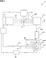
- a drop detection device 11 according to a very simplified, basic embodiment of the invention is shown schematically on a metering valve DV.
- the drop detection device 11 comprises a signal generation unit 20.
- the signal generation unit 20 generates a carrier signal TS with a defined pulse frequency or carrier frequency.
- the carrier signal TS is transmitted to a modulation unit 30 which is set up to apply a modulation signal to the carrier signal TS (depending on a drop to be detected).
- the modulation unit 30 comprises an interspace in which a trajectory T of a drop TR which was emitted by the metering valve DV runs.
- the modulation unit 30 comprises in the in Figure 1
- the embodiment shown has a first signal conversion unit 31 which converts the generated carrier signal TS into a signal form with which an interaction of the carrier signal TS with a drop TR to be detected is possible.
- a second signal conversion unit 32 is arranged opposite the first signal conversion unit 31, which converts a measurement signal MS, possibly modulated by a drop TR to be detected, back into an electrically transmittable and electronically further processable Signal EMS converts.
- the signal conversion units 31, 32 can also have additional signal feed units and signal output units (see FIG Figure 2 ), which ensure an undisturbed supply and discharge of a signal that may interact with a drop TR in the space between the two signal conversion units 31, 32.
- the electrical, modulated measurement signal EMS is transmitted from the modulation unit 30 to an evaluation unit 50.
- the evaluation unit 50 comprises a demodulation unit 40 which demodulates the electrically modulated measurement signal EMS. That is, a modulation signal MOD (which contains the information as to whether there has been an interaction between the carrier signal and a drop) of the electrically modulated measurement signal EMS is separated from the carrier signal TS and then transmitted to a modulation value determination unit 51, which in the in Figure 1
- the first exemplary embodiment shown is part of a control device 60.
- the modulation value determination unit 51 determines comparison values, such as amplitude comparison values or phase comparison values, on the basis of the modulation signal MOD.
- the comparison values are transmitted to a detection filter unit 52 which, on the basis of the comparison values mentioned and reference values determined beforehand, checks whether a drop TR with the desired dimensions has been dispensed by the metering valve DV or not.
- the signal generation unit 20 can be electrically connected to the demodulation unit 40 in order to transmit a reference signal RS, for example the generated carrier signal TS or a carrier signal shifted by a certain phase, to the demodulation unit 40.
- the signal generation unit 20 and / or the evaluation unit 50 can additionally be connected for signaling purposes to a valve control unit 70 of the metering valve DV.
- the control unit of the metering valve DV transmits a start signal IS or trigger signal to the signal generation unit 20 and / or to the evaluation unit 50, with which the units 20, 50 can be started each time shortly before the metering valve DV emits a drop TR.
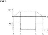
- the valve control unit 70 defines both the start time of a readout window and the start of the generation of the carrier signal TS.
- the start signal IS is sent to the evaluation unit 50 to determine the start time of the readout window.
- the start signal is also transmitted to the signal generation unit 20.
- a process control computer 80 which receives information from the control device 60 about the current drop dosage.
- the start signal IS is also transmitted to the evaluation unit 50, which is activated with a delay and starts a drop detection at time t 2 .
- the tappet of the metering valve DV reaches a position in which the valve is completely open.
- the actuation of the metering valve is stopped with the aid of the control signal of the metering valve.
- a closing process of the metering valve DV is started. A drop is emitted by the metering valve DV between times t 2 and t 3 and the drop is detected with the aid of the evaluation unit 50.
- a drop detection device 11a according to a particularly preferred embodiment of the invention is shown in detail.
- the drop detection device 11a comprises like that in FIG Figure 1
- the drop detection device 11 shown according to a first exemplary embodiment of the invention has a signal generation unit 20, which in FIG Figure 3 is shown in dashed lines.
- the signal generation unit 20 includes in this Exemplary embodiment, a transmission signal generation unit 21 which generates a transmission signal PWM_5 with a defined, predeterminable pulse frequency, for example as a pulsed square-wave signal.
- the generated transmission signal PWM_5 is transmitted to a power amplifier 24, which amplifies the transmission signal PWM_5 into a carrier signal TS.
- the signal generation unit 20 comprises a second signal generation unit 23, which is set up to transmit pulsed control signals PWM_1,..., PWM_4 that are phase-shifted with respect to the carrier signal to a mixer unit 43 of a demodulation unit 40.
- the pulse frequency of the control signals PWM_1, ..., PWM_4 for the mixer 43 is always the same as the frequency of the transmission signal PWM_5.
- the phase shift between the control signals PWM_1, ..., PWM_4 and the transmission signal is variable.
- the pulse frequency is preferably 450 kHz ⁇ 15 kHz.
- the definition of the frequency of the carrier signal is used to ensure that the received signal (the carrier signal and sidebands created by the amplitude modulation caused by the drop) can optimally pass through the bandpass filter.
- a sideband is then selected by setting the phase position between the carrier signal and the control signals of the demodulation unit.
- the carrier frequency must be higher than twice the frequency resulting from the time the droplets pass through the modulation unit 30.
- the carrier signal TS is transmitted from the amplifier 24 to a modulation unit 30.
- the modulation unit 30 comprises like that in FIG Figure 1 Modulation unit 30 shown first and second signal conversion units 31, 32.
- the first signal conversion unit 31 comprises a light emission unit.
- the light-emitting unit can be, for example, a light-emitting diode which lights up as a function of the carrier signal TS applied to the light-emitting diode.
- the carrier signal TS which is initially present as a pulsed electrical current, is converted into a pulsed light signal.
- the first signal conversion unit 31 is connected here to a first optical waveguide L1, which feeds the pulsed light signal to an intermediate space ZR in which a trajectory of a drop TR of a metering valve to be detected runs.
- a second optical waveguide L2 is arranged opposite the first optical waveguide L1, which is connected to a second signal conversion unit 32 and forwards a light signal MS, possibly modulated by a drop TR, to the second signal conversion unit 32.
- the second signal conversion unit 32 comprises, for example, a photodetector which receives the modulated light signal MS and converts it again into an electrical modulated signal EMS that can be transported by an electrical line.
- the electrically modulated signal EMS is then transmitted from the modulation unit 30 to an evaluation unit 50, which also has a demodulation unit 40.
- the demodulation unit 40 comprises an amplifier unit 41 which amplifies the modulated signal EMS.
- the amplifier unit 41 is controlled by the signal generating unit 20 via a control signal output 22 and serves on the one hand to preamplify the modulated signal EMS detected by the photodetector 32 and on the other hand as a transimpedance amplifier.
- the photodetector 32 is biased in the reverse direction and operated in a quasi-short circuit. As a result, the photodetector 32 only emits a current that is linearly dependent on the illuminance over many orders of magnitude without a voltage fluctuation.
- the bandwidth of the detector which is normally limited by the junction capacitance, is significantly higher, since the capacitance is not charged.
- the preload also results in a further reduction in capacity, which is accompanied by a further increase in the achievable bandwidth.
- the transimpedance amplifier also converts the current signal into a voltage signal.
- the gain factor of this implementation is adjustable. This achieves a maximum voltage-controlled signal modulation that is dependent on the drop shadowing.
- the demodulation unit 40 comprises a filter unit 42.
- the filter unit 42 can, for example, comprise a bandpass filter which only allows the two sidebands and the carrier frequency of the modulated signal EMS to pass.
- the filter unit 42 also removes any interference signals - caused by external light irradiation - for example at frequencies that are far removed from the pulse frequency of the carrier signal TS.
- the filter unit 42 preferably a steep-edged bandpass filter, also removes harmonics generated by the pulse width modulation.
- the modulated measurement signal EMS filtered in this way is then passed on to a mixer 43, which mixes the modulated and filtered measurement signal EMS with the pulsed control signals PWM_1, ..., PWM_4 generated by the second signal generation unit 23 and phase-shifted with respect to the carrier signal, and an in-phase signal or an in-phase component I is transmitted to an in-phase signal amplifier 44 and a quadrature signal or a quadrature component Q is transmitted to a quadrature signal amplifier 45.
- the in-phase control of the mixer 43 results in the demodulation of only one sideband.
- the in-phase signal amplifier 44 and the quadrature signal amplifier 45 are of one Control signal output 22 of the signal generation unit 20 is activated.
- the amplifiers 41, 44, 45 are controlled separately from one another.
- rheostat variable resistor
- I2C bus data bus
- I2C bus data bus
- Each rheostat (and thus amplifier) is adjusted individually.
- the setting of the amplifier 41 is completely independent of the amplifiers 44 and 45 in terms of value.
- the amplifiers 44 and 45 however, always have the same value in order not to change the relationship between the I and Q signals. However, these two are also controlled separately from each other.
- the functioning of the mixer unit 43 is shown in FIG Figure 4 shown in detail and will be explained in more detail later.
- the in-phase component I and the quadrature component Q form the modulation signal MOD.
- the evaluation unit 50 includes those already in connection with Figure 1 described modulation value determination unit 51 and the detection filter unit 52. These sub-units of the evaluation unit 50 are in the Figure 3
- the second exemplary embodiment shown is part of the control device 60.
- the modulation value determination unit 51 the digitized signal components I, Q are mathematically processed and transformed into amplitude and phase information, for example with the help of polar coordinate transformation.
- the detection filter unit 52 can be designed, for example, as a parameterizable software filter with which it is determined on the basis of the recorded information whether a drop is passing the sensor system formed by the modulation unit 30 Has. Before the system 11a can start its regular operation, it must be set by two separate initialization processes.
- all hardware assemblies must be set to an optimal working point for detection.
- These settings include the determination of the operating point of the light sensor 32 by the carrier signal duty cycle, the frequency adjustment of the carrier signal TS to the filter characteristic of the bandpass filter 42, the setting of the phase position of the mixer signals PWM_1 ... PWM_4 in relation to the carrier signal for precise sideband selection, the finding of the optimal amplification factor of the transimpedance amplifier 41 as well as the signal adaptation of the I and Q signals for the AD converter of the inputs 53, 54 by the ADC preamplifier 44, 45.
- all parameters of the detection filter unit 52 must be adjusted in relation to the expected target droplets TR. This includes the time window for searching for the derivation maxima for the amplitude and phase values, the permitted relative deviation widths of the comparison values from the reference values of the amplitude and phase values, and the permitted absolute ranges of the reference values of the amplitude and phase values.
- Both the hardware and the filter settings can be set manually or through automatic training processes. These settings are required for obtaining the modulation value and for evaluating the signal with regard to the detection of a drop TR.
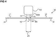
- the detection method according to the invention is very insensitive to scattered light and other disturbances, but highly sensitive to the useful signal, it is advantageously not necessary to add additional optical elements, such as, for example, to the emission window 14 of the first light guide element L1 or the detection window 15 of the second light guide element L2.
- B. lens systems or the like to use. From- or entry sides of the optical waveguide elements L1, L2 must be as perpendicular as possible to the longitudinal axis of the optical waveguide L1, L2. Since the light sensor 32 and the light emission unit 31 are located outside the working area occupied by the metering valve DV, the light sensor 32 and the light emission unit 31 can be dimensioned independently of the restricted space conditions prevailing in the area of the nozzle adjusting nut DEM of the metering valve.
- the light emission unit 31 serves as a signal converter which converts the unmodulated electrical carrier signal TS into an unmodulated light signal LS.
- the light sensor 32 serves as a signal converter which converts the modulated light signal MS into a modulated electrical measurement signal EMS.
- the subsequent processing of the modulated electrical measurement signal EMS is related to the Figures 3 and 5 described in more detail.
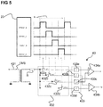
- the sideband used for the demodulation is determined by a suitable choice of the phase position of the modulated measurement signal EMS in relation to four control signals PWM_1, ..., PWM_4, which control the switches 432a, 432b, 432c, 432d of the mixer 43, via the differential amplifiers 434a, 434b, which are connected downstream of the integrators 433a, 433b, 433c, 433d, are selected.
- In-phase signals I and quadrature signals Q are generated as output signals from differential amplifiers 434a, 434b.
- the mixer unit 43 functions as follows: A measurement signal EMS is transmitted from the transmitter 431 to the input of the mixer unit 43.
- the transformer 431 is used to adjust the power between different components as well as to balance signals and remove existing DC components.
- the mixer 43 further comprises a resistor R which is connected in series to the output of the transformer and together with the integrators 433a, 433b, 433c, 433d forms a filter.
- An average value integrated in the first quarter wave is applied to the positive input of the first differentiator 434a marked with "+” and an average value integrated in the third quarter wave is applied to the negative input of the first differentiator 434a marked with "-”.
- An average value integrated in the second quarter wave is applied to the positive input of the second differentiator 434b and an average value integrated in the fourth quarter wave is applied to the negative input of the second differentiator 434b.
- An in-phase signal I in the baseband is generated at the output of the first differentiator 434a and a quadrature signal Q in the baseband is generated at the output of the second differentiator. Details on how such mixing units work can be found in US 6,230,000 B1 described.
- FIG 6 an external view (of a housing) of a control device 60 is shown, with which the control of individual units of a drop detection device 11, 11a, 11b, the evaluation of measurement signals, the monitoring of the functionality of individual units and the setting and coordination of individual system parameters can be performed.
- the entire electronics are housed in this housing. In principle, this concerns the entire system of drop detection including the optoelectronic signal converter (receiver photodiode 32 and transmitter LED 31). These represent the limit to the “optical path”, ie the transmission optical waveguide L1, the emission window and the drop path T, which is external.
- the data bus connection DB will serve, among other things, for communication with the valve control unit. For example, the current status of the drop detection or statistics on the past dosing processes (number of detected errors and when they occurred) can be transmitted to them via this data bus connection DB.
- Another possible application for this data bus connection DB is that the drop detection could request the valve control unit via this bus to intentionally initiate incorrect metering in order to ensure correct functioning to check the drop detection. This would then have to reliably detect these intentional incorrect dosages.
- Part of the control device 60 is also a communication interface I / O, with which trigger signals are received from the valve control unit 70 and via which information on the system status of the drop detection device and the dosage status is output.
- the control device 60 also has an input RX, which serves as a connection between the receiving optical waveguide L2 and the photo element 32.
- An output TX is used to connect the transmission optical waveguide L1 to the transmission light-emitting diode 31.
- Another input U S is used to supply voltage to the control device 60.
- An additional input PGM can be used as a programming socket for firmware transfer.
- the control device 60 comprises two pressure switches S1, S2 for tuning individual units of a drop detection device. For example, by pressing the one switch S1 for a defined period of time (here for example 2 s), a first training mode, a "hardware training mode", is switched on in which, for example, a pulse width of the carrier signal TS is set so that an optimal Brightness of the light emitting unit 31 with respect to the residual light reaching the light sensor unit based on the light beam formed of the carrier signal TS is achieved, the setting of a frequency of the pulsed carrier signal TS so that the two sidebands of the modulated signal EMS can pass a filter unit 42 connected downstream of the sensor device, the setting of the phase position of the carrier signal TS via the signal PWM_5 in relation to the Control signals PWM_1, ..., PWM_4, with which the mixer unit 43 belonging to the demodulation unit is controlled, and the setting of the amplifier units 44 and 45 for voltage adjustment and the amplifier unit 41, which acts as a transimpedance amplifier, takes place.
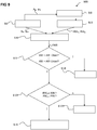
- FIG 8 is the operating principle 800 of the Figures 1 and 3 illustrated modulation value determination unit 51 of an evaluation unit 50 in detail.
- the modulation value determination unit 51 acquires in-phase and quadrature components I, Q from the in Figure 2 Inputs 53, 54 of the control unit 60 shown downstream of the AD converters of the evaluation unit 50.
- the sampling of the in-phase signal I and the quadrature signal Q takes place continuously.
- the two values I, Q are preferably obtained at the same time.
- the values I, Q pass through a median and mean value filter before they are further processed in order to remove extreme values caused by interference radiation, ADC conversion errors, etc.
- step 8.II the signal components I, Q are converted into a signal MOD (A, ⁇ ) with the aid of a polar coordinate transformation, which comprises information relating to the amplitude A and the phase ⁇ of the modulation signal MOD.
- a polar coordinate transformation which comprises information relating to the amplitude A and the phase ⁇ of the modulation signal MOD.
- I and Q correspond to the amplitudes of the in-phase and quadrature components I, Q of the demodulated signal and the modulation signal MOD, respectively.
- the amplitude A and the phase ⁇ are time-dependent quantities. Due to the high sampling rate and the associated rapid acquisition of values, the calculations according to equations 1 and 2 are carried out using look-up tables with linear inter-value interpolation.
- step 8.III the amplitude A and the phase ⁇ of the modulation signal MOD (A, ⁇ ) are derived over time.
- step 8.IV derivative values dA / dt, d ⁇ / dt are considered in a predetermined time interval I T and a predetermined number of maximum values of the derivative values dA / dt, d ⁇ / dt, for example the largest 10 values, in the time interval I T selected.
- the time interval I T can, for example, be specified in advance when the overall system is initialized or during the detection filter training.
- modulation values A M , ⁇ M for the amplitude A and the phase ⁇ are formed as a sum over the number of maximum values determined in advance.
- step 9.IV a deviation AW of the modulation values A M , ⁇ M determined by the modulation value determination unit 51 for the amplitude A and the phase ⁇ from the reference values RW A , RW ⁇ is calculated.
- step 9.V a comparison is made between the respectively determined deviation AW and a maximum permitted relative deviation upwards AW_Oben or downwards AW_Bottom. If the deviation is too great, which is what in Figure 9 is marked with "j", it is reported in step 9.VI that a faulty drop has been determined.
- the amount of the permitted deviation AW_Oben or AW_Bown is determined on the basis of one or more target drops during an initialization process or in the aforementioned software training mode of the drop detection device.
- the reference values RW A , RW ⁇ ie, for example, the mean values over the modulation values A M , von M of past drops are monitored.
- step 9.VII it is determined whether the reference values RW A , RW ⁇ for amplitude A and phase ⁇ are in a predetermined absolute value interval ARI, PRI.
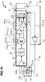
- the capacitor 31a is positioned in such a way that a trajectory T of a drop TR, which was emitted by a metering valve DV, runs between the capacitor plates 31b, 31c of the capacitor 31a, perpendicular to the course of the field lines of the developing electric field.
- the coupling achieved between the transmitting and receiving branches is influenced. This coupling is dependent on the reactance X c of the capacitor 31a. Slight changes in the reactance X c of the capacitor 31a, which are caused by a drop TR flying through, lead to a modulation of the carrier signal TS.
- f is the frequency of the carrier signal TS applied to the capacitor 31a and C is the capacitance of the capacitor 31a.
- f is the frequency of the carrier signal TS applied to the capacitor 31a
- C is the capacitance of the capacitor 31a.
- ⁇ 0 stands for the dielectric constant
- ⁇ r for the permittivity of the capacitor 31a
- A for the area of the capacitor plates 31b, 31c and the parameter d for the distance between the capacitor plates 31b, 31c. Since the area A of the capacitor plates 31b, 31c and the distance d between the capacitor plates 31b, 31c are not changed, a change in the capacitance C and thus the reactance X c is only dependent on a change ⁇ r in the material-specific permittivity ⁇ r . If a drop TR enters the space between the two capacitor plates 31b, 31c, the permittivity ⁇ r in this area changes as a function of the dosage and the material of the drop.
- the modulation of the carrier signal TS thus results from the fluctuation in the permittivity ⁇ r caused by the drop.
- Optical waveguides are not necessary in this embodiment.
- the capacitor plates 31b, 31c must be positioned relatively close to the trajectory of the drop TR and thus to the outlet of the metering valve DV.
- the measurement signal MS possibly modulated by a drop TR, is transmitted as a modulated electrical measurement signal EMS from the modulation unit 30 to an evaluation unit 50.
- the embodiment shown has a demodulation unit 40 which also has essentially the same components with the same functions as the demodulation unit 40 in the embodiment according to FIG Figure 2 .
- the demodulation unit 40 thus has an amplifier unit 41 which amplifies the modulated electrical measurement signal EMS.
- the amplifier unit 41 serves to pre-amplify the modulated electrical measurement signal EMS detected by the modulation unit 30 and is controlled by a control signal output 22 of the signal generation unit 20. It is designed here as a normal voltage amplifier and not as a transimpedance amplifier as in the case of the optical detection variant.
- the demodulation unit 40 also comprises a filter unit 42.
- the filter unit 42 can, for example comprise a bandpass filter which only allows the two sidebands and the carrier frequency of the modulated electrical measurement signal EMS to pass.
- the filter unit 42 also removes any interference signals caused by interference fields which, for example, include frequencies that are far removed from the frequency of the carrier signal TS.
- the filter unit preferably a steep-edged bandpass filter, also removes harmonics generated by the pulse width modulation.
- the modulated electrical measurement signal EMS filtered in this way is then forwarded to a mixer 43, which mixes the modulated and filtered measurement signal EMS with the pulsed control signals PWM_1, ..., PWM_4 generated by the second signal generation unit 23 and out of phase with the carrier signal, and into an in-phase Signal amplifier 44 transmits an in-phase signal or an in-phase component I and a quadrature signal or a quadrature component Q is transmitted to a quadrature signal amplifier 45.
- the in-phase control of the mixer 43 results in the demodulation of only one sideband.
- the in-phase signal amplifier 44 and the quadrature signal amplifier 45 are controlled by a control signal output 22 of the signal generation unit 20.
- the amplifiers 41, 44, 45 are controlled separately from one another. They are set via a variable resistor (rheostat) that can be programmed via a data bus (eg I2C bus). Each rheostat (and thus amplifier) is adjusted individually.
- the setting of the amplifier 41 is completely independent of the amplifiers 44 and 45 in terms of value. However, the amplifiers 44 and 45 always have the same value in order not to change the relation between the I and Q signals. Nevertheless, these two are also controlled separately from each other.
- the control unit 60 comprises inputs 53, 54 for the signal components I, Q.
- the inputs 53, 54 are also followed by AD converters (not shown) which convert the analog signal components I, Q into digital signals.
- the amplifiers 44, 45 of the demodulation unit 40 can be adjusted in terms of their gain factor and are used to raise the signal components I, Q generated by the mixer unit 43 to a voltage level that is optimal for the AD converter. This ensures maximum utilization of the converter resolution.
- the evaluation unit also includes 50 also has a modulation value determination unit 51 and a detection filter unit 52.
- the evaluation unit 50 is in the in Figure 9 The exemplary embodiment shown is part of a control unit 60.
- the digitized signal components I, Q are mathematically processed in the modulation value determination unit 51 and transformed into amplitude and phase information, for example with the aid of polar coordinate transformation.
- the detection filter unit 52 can be designed, for example, as a parameterizable software filter with which it is determined on the basis of the recorded information whether a drop has passed the sensor system formed by the modulation unit 30a. Before the system 11a can start its regular operation, it must be set by two separate initialization processes. On the one hand, all hardware assemblies must be set to an optimal operating point for detection. These settings include the frequency adjustment of the carrier signal TS to the filter characteristic of the bandpass filter 42, the setting of the phase position of the mixer signals PWM_1 ...
- PWM_4 in relation to the carrier signal for precise sideband selection, the finding of the optimal gain factor of the transimpedance amplifier 41 and the signal adaptation of the I and Q Signals for the AD converter of the inputs 53, 54 through the ADC preamplifier 44, 45.
- all parameters of the detection filter unit 52 must be adjusted in relation to the expected target droplets TR. This includes the time window for searching for the derivation maxima for the amplitude and phase values, the permitted relative deviation ranges of the comparison values from the reference values of the amplitude and phase values and the permitted absolute ranges of the reference values of the amplitude and phase values. Both the hardware and the filter settings can be set manually or through automatic training processes
- unit is also intended to include components which consist of several, possibly also spatially separated, subunits.
- unit can also mean a conceptual logical unit, so that one and the same hardware component comprises several of these logical units can. This applies, for example, in particular to the modulation unit 30, the demodulation unit 40 and possibly also to the signal generation unit 20 and the evaluation unit 50.
Landscapes
- Chemical & Material Sciences (AREA)
- Physics & Mathematics (AREA)
- General Physics & Mathematics (AREA)
- Life Sciences & Earth Sciences (AREA)
- Pathology (AREA)
- Analytical Chemistry (AREA)
- Biochemistry (AREA)
- General Health & Medical Sciences (AREA)
- Health & Medical Sciences (AREA)
- Immunology (AREA)
- Dispersion Chemistry (AREA)
- Engineering & Computer Science (AREA)
- General Engineering & Computer Science (AREA)
- Signal Processing (AREA)
- Geophysics (AREA)
- General Life Sciences & Earth Sciences (AREA)
- Mechanical Engineering (AREA)
- Fluid Mechanics (AREA)
- Geophysics And Detection Of Objects (AREA)
- Investigating Or Analysing Materials By Optical Means (AREA)
- Arrangements For Transmission Of Measured Signals (AREA)
- Measuring Volume Flow (AREA)
- Infusion, Injection, And Reservoir Apparatuses (AREA)
Applications Claiming Priority (2)
| Application Number | Priority Date | Filing Date | Title |
|---|---|---|---|
| DE102015117248.8A DE102015117248A1 (de) | 2015-10-09 | 2015-10-09 | Tropfendetektionseinrichtung |
| PCT/EP2016/073851 WO2017060336A1 (de) | 2015-10-09 | 2016-10-06 | Tropfendetektionseinrichtung |
Publications (2)
| Publication Number | Publication Date |
|---|---|
| EP3359305A1 EP3359305A1 (de) | 2018-08-15 |
| EP3359305B1 true EP3359305B1 (de) | 2020-12-02 |
Family
ID=57123990
Family Applications (1)
| Application Number | Title | Priority Date | Filing Date |
|---|---|---|---|
| EP16779054.2A Active EP3359305B1 (de) | 2015-10-09 | 2016-10-06 | Tropfendetektionseinrichtung |
Country Status (7)
| Country | Link |
|---|---|
| US (1) | US10753850B2 (enExample) |
| EP (1) | EP3359305B1 (enExample) |
| JP (1) | JP6899384B2 (enExample) |
| KR (1) | KR102601948B1 (enExample) |
| CN (1) | CN108136432A (enExample) |
| DE (1) | DE102015117248A1 (enExample) |
| WO (1) | WO2017060336A1 (enExample) |
Families Citing this family (6)
| Publication number | Priority date | Publication date | Assignee | Title |
|---|---|---|---|---|
| DE102017103876A1 (de) | 2017-02-24 | 2018-08-30 | Vermes Microdispensing GmbH | Führungssystem für Detektionsvorrichtungen |
| DE102018002129A1 (de) * | 2018-03-16 | 2019-09-19 | Focke & Co. (Gmbh & Co. Kg) | Verfahren zur automatischen Überwachung der Leimabgabe eines Leimventils |
| JP7183742B2 (ja) * | 2018-11-29 | 2022-12-06 | 株式会社リコー | 液吐出ヘッド、液吐出装置、及び液吐出方法 |
| EP3835819B1 (en) | 2019-12-10 | 2025-07-16 | Melexis Technologies NV | Optical range calculation apparatus and method of range calculation |
| EP4245135A1 (de) | 2022-03-16 | 2023-09-20 | Bayer AG | Durchführen und dokumentieren einer applikation von pflanzenschutzmittel |
| EP4339653B1 (de) * | 2022-09-19 | 2024-07-17 | Leuze electronic GmbH + Co. KG | Optischer sensor |
Family Cites Families (22)
| Publication number | Priority date | Publication date | Assignee | Title |
|---|---|---|---|---|
| GB1520606A (en) * | 1976-04-30 | 1978-08-09 | Burron Medical Prod Inc | Electronically controlled intravenous infusion set |
| US4260882A (en) | 1978-05-17 | 1981-04-07 | Barnes Austen B | Light sensitive detection circuit |
| US4255754A (en) | 1979-03-19 | 1981-03-10 | Xerox Corporation | Differential fiber optic sensing method and apparatus for ink jet recorders |
| US4410895A (en) | 1981-10-26 | 1983-10-18 | Xerox Corporation | Ink jet sensor method and apparatus |
| US4577197A (en) | 1985-01-17 | 1986-03-18 | Xerox Corporation | Ink jet printer droplet height sensing control |
| US5275787A (en) * | 1989-10-04 | 1994-01-04 | Canon Kabushiki Kaisha | Apparatus for separating or measuring particles to be examined in a sample fluid |
| US5267978A (en) * | 1990-08-29 | 1993-12-07 | Random Corporation | Pulsed drop detector for intravenous systems |
| US5650609A (en) | 1995-05-15 | 1997-07-22 | Phoenix International Corporation | Seed monitoring system for counting seeds as they are dispensed through a seed planting tube |
| DK114497A (da) * | 1997-10-07 | 1999-04-08 | Alka Electronic Aps | Optisk flowmåler |
| US6230000B1 (en) | 1998-10-15 | 2001-05-08 | Motorola Inc. | Product detector and method therefor |
| EP1332050A2 (en) * | 2000-11-09 | 2003-08-06 | Therics, Inc. | Method and apparatus for obtaining information about a dispensed fluid during printing |
| JP2002191692A (ja) * | 2000-12-25 | 2002-07-09 | Tatsuhiko Matsuura | 点滴監視装置及びそれを備えた点滴監視制御装置 |
| JP2004528662A (ja) | 2001-06-04 | 2004-09-16 | セオス インダストリアル ピーティーワイ リミテッド | モニタ方法およびシステム |
| US6807497B2 (en) * | 2001-12-17 | 2004-10-19 | Agilent Technologies, Inc. | Laser measurement system with digital delay compensation |
| JP3915510B2 (ja) * | 2001-12-26 | 2007-05-16 | セイコーエプソン株式会社 | インクジェット式記録装置とその駆動電圧補正方法 |
| JP4682673B2 (ja) * | 2005-04-01 | 2011-05-11 | 株式会社デンソー | 電波時計 |
| CN101365609A (zh) * | 2005-12-13 | 2009-02-11 | Tk电子控股公司 | 信号处理系统和方法 |
| EP1946843A1 (en) | 2006-12-21 | 2008-07-23 | Allegro Research Limited | Apparatus and method for monitoring and measurement of droplets |
| JP4249798B1 (ja) * | 2008-07-22 | 2009-04-08 | オーム電機株式会社 | 検出装置および検出方法 |
| US20120225475A1 (en) | 2010-11-16 | 2012-09-06 | 1087 Systems, Inc. | Cytometry system with quantum cascade laser source, acoustic detector, and micro-fluidic cell handling system configured for inspection of individual cells |
| CA2853093C (en) | 2011-10-21 | 2020-01-14 | Acea Biosciences, Inc. | System and method for detecting multiple-excitation-induced light in a flow channel |
| CN103596260B (zh) * | 2012-08-17 | 2017-06-16 | 京信通信系统(中国)有限公司 | 多载波gsm系统的时隙同步方法和系统 |
-
2015
- 2015-10-09 DE DE102015117248.8A patent/DE102015117248A1/de not_active Ceased
-
2016
- 2016-10-06 JP JP2018517551A patent/JP6899384B2/ja active Active
- 2016-10-06 US US15/765,594 patent/US10753850B2/en active Active
- 2016-10-06 CN CN201680058999.2A patent/CN108136432A/zh active Pending
- 2016-10-06 KR KR1020187010345A patent/KR102601948B1/ko active Active
- 2016-10-06 EP EP16779054.2A patent/EP3359305B1/de active Active
- 2016-10-06 WO PCT/EP2016/073851 patent/WO2017060336A1/de not_active Ceased
Non-Patent Citations (1)
| Title |
|---|
| None * |
Also Published As
| Publication number | Publication date |
|---|---|
| KR20180064412A (ko) | 2018-06-14 |
| JP2019500578A (ja) | 2019-01-10 |
| WO2017060336A1 (de) | 2017-04-13 |
| EP3359305A1 (de) | 2018-08-15 |
| DE102015117248A1 (de) | 2017-04-13 |
| US20190078996A1 (en) | 2019-03-14 |
| KR102601948B1 (ko) | 2023-11-14 |
| JP6899384B2 (ja) | 2021-07-07 |
| CN108136432A (zh) | 2018-06-08 |
| US10753850B2 (en) | 2020-08-25 |
Similar Documents
| Publication | Publication Date | Title |
|---|---|---|
| EP3359305B1 (de) | Tropfendetektionseinrichtung | |
| EP0439011B1 (de) | Abstandsmessgerät | |
| AT412023B (de) | Verfahren und einrichtung zur elektrooptischen distanzmessung | |
| EP1913420B1 (de) | Verfahren zur lichtlaufzeitmessung | |
| DE2735479C2 (de) | Lichtleiter-Nachrichtenübertragungssystem | |
| EP1910773B1 (de) | Verfahren und vorrichtung zur entfernungsmessung mittels kapazitiven oder induktiven sensoren | |
| EP0547415A1 (de) | Einrichtung zur berührungslosen Steuerung einer Sanitärarmatur | |
| EP2405283A1 (de) | Optoelektronische Messanordnung mit einer Kompensationslichtquelle | |
| WO2013170982A1 (de) | Optisches entfernungsmessgerät mit kalibriereinrichtung zum berücksichtigen von übersprechen | |
| DE3875131T2 (de) | Verfahren und vorrichtung zur signaluebertragung zwischen zwei teilen. | |
| DE102015006174B3 (de) | Vorrichtung und Verfahren zur Vermessung einer optischen, kapazitiven, induktiven Übertragungsstrecke | |
| CH665291A5 (de) | Verfahren zur automatischen stabilisierung des von einem szintillationsdetektor gelieferten messergebnisses und anordnung zur durchfuehrung des verfahrens. | |
| EP1191697B1 (de) | Lokaloszillator zur Erzeugung eines HF-Signals zur Direktmischung mittels Avalanche-Fotodioden | |
| EP3359951A1 (de) | Lichtleiteranordnung zur optischen tropfendetektion | |
| EP3928119A1 (de) | Radarsensor für die fabrik- und logistikautomation | |
| DE102010002201B4 (de) | Induktiver Näherungsschalter | |
| DE102020125270A1 (de) | Lidar-system und dessen steuerungsverfahren | |
| EP3527958A1 (de) | Verfahren zur detektion einer schaumgrenze und entsprechend ausgestattete vorrichtung | |
| DE102015101351A1 (de) | System zur kontaktlosen Energie- und Datenübertragung | |
| DE19510452C2 (de) | Sende- und Empfangseinrichtung zur drahtlosen Abfrage eines physikalischen Parameters | |
| EP4632425A1 (de) | Radar-messgerät | |
| WO2016202533A1 (de) | Verfahren und vorrichtung zur bestimmung des füllstandes eines in einem behälter befindlichen füllgutes | |
| DE10200905B4 (de) | Photoelektrischer Schalter | |
| EP1405435A2 (de) | Vorrichtung und verfahren zur konstanthaltung der sendeleistung von funkgeräten | |
| EP3017323B1 (de) | Verfahren und vorrichtungen zur bestimmung der entfernung eines objektes |
Legal Events
| Date | Code | Title | Description |
|---|---|---|---|
| STAA | Information on the status of an ep patent application or granted ep patent |
Free format text: STATUS: THE INTERNATIONAL PUBLICATION HAS BEEN MADE |
|
| PUAI | Public reference made under article 153(3) epc to a published international application that has entered the european phase |
Free format text: ORIGINAL CODE: 0009012 |
|
| STAA | Information on the status of an ep patent application or granted ep patent |
Free format text: STATUS: REQUEST FOR EXAMINATION WAS MADE |
|
| 17P | Request for examination filed |
Effective date: 20180309 |
|
| AK | Designated contracting states |
Kind code of ref document: A1 Designated state(s): AL AT BE BG CH CY CZ DE DK EE ES FI FR GB GR HR HU IE IS IT LI LT LU LV MC MK MT NL NO PL PT RO RS SE SI SK SM TR |
|
| AX | Request for extension of the european patent |
Extension state: BA ME |
|
| DAV | Request for validation of the european patent (deleted) | ||
| DAX | Request for extension of the european patent (deleted) | ||
| STAA | Information on the status of an ep patent application or granted ep patent |
Free format text: STATUS: EXAMINATION IS IN PROGRESS |
|
| 17Q | First examination report despatched |
Effective date: 20191126 |
|
| GRAP | Despatch of communication of intention to grant a patent |
Free format text: ORIGINAL CODE: EPIDOSNIGR1 |
|
| STAA | Information on the status of an ep patent application or granted ep patent |
Free format text: STATUS: GRANT OF PATENT IS INTENDED |
|
| INTG | Intention to grant announced |
Effective date: 20200706 |
|
| GRAS | Grant fee paid |
Free format text: ORIGINAL CODE: EPIDOSNIGR3 |
|
| GRAA | (expected) grant |
Free format text: ORIGINAL CODE: 0009210 |
|
| STAA | Information on the status of an ep patent application or granted ep patent |
Free format text: STATUS: THE PATENT HAS BEEN GRANTED |
|
| AK | Designated contracting states |
Kind code of ref document: B1 Designated state(s): AL AT BE BG CH CY CZ DE DK EE ES FI FR GB GR HR HU IE IS IT LI LT LU LV MC MK MT NL NO PL PT RO RS SE SI SK SM TR |
|
| REG | Reference to a national code |
Ref country code: GB Ref legal event code: FG4D Free format text: NOT ENGLISH |
|
| REG | Reference to a national code |
Ref country code: AT Ref legal event code: REF Ref document number: 1340319 Country of ref document: AT Kind code of ref document: T Effective date: 20201215 Ref country code: CH Ref legal event code: EP |
|
| REG | Reference to a national code |
Ref country code: IE Ref legal event code: FG4D Free format text: LANGUAGE OF EP DOCUMENT: GERMAN |
|
| REG | Reference to a national code |
Ref country code: DE Ref legal event code: R096 Ref document number: 502016011865 Country of ref document: DE |
|
| REG | Reference to a national code |
Ref country code: FI Ref legal event code: FGE |
|
| REG | Reference to a national code |
Ref country code: CH Ref legal event code: NV Representative=s name: VALIPAT S.A. C/O BOVARD SA NEUCHATEL, CH |
|
| REG | Reference to a national code |
Ref country code: SE Ref legal event code: TRGR |
|
| PG25 | Lapsed in a contracting state [announced via postgrant information from national office to epo] |
Ref country code: GR Free format text: LAPSE BECAUSE OF FAILURE TO SUBMIT A TRANSLATION OF THE DESCRIPTION OR TO PAY THE FEE WITHIN THE PRESCRIBED TIME-LIMIT Effective date: 20210303 Ref country code: NO Free format text: LAPSE BECAUSE OF FAILURE TO SUBMIT A TRANSLATION OF THE DESCRIPTION OR TO PAY THE FEE WITHIN THE PRESCRIBED TIME-LIMIT Effective date: 20210302 Ref country code: RS Free format text: LAPSE BECAUSE OF FAILURE TO SUBMIT A TRANSLATION OF THE DESCRIPTION OR TO PAY THE FEE WITHIN THE PRESCRIBED TIME-LIMIT Effective date: 20201202 |
|
| REG | Reference to a national code |
Ref country code: NL Ref legal event code: MP Effective date: 20201202 |
|
| PG25 | Lapsed in a contracting state [announced via postgrant information from national office to epo] |
Ref country code: BG Free format text: LAPSE BECAUSE OF FAILURE TO SUBMIT A TRANSLATION OF THE DESCRIPTION OR TO PAY THE FEE WITHIN THE PRESCRIBED TIME-LIMIT Effective date: 20210302 Ref country code: PL Free format text: LAPSE BECAUSE OF FAILURE TO SUBMIT A TRANSLATION OF THE DESCRIPTION OR TO PAY THE FEE WITHIN THE PRESCRIBED TIME-LIMIT Effective date: 20201202 Ref country code: LV Free format text: LAPSE BECAUSE OF FAILURE TO SUBMIT A TRANSLATION OF THE DESCRIPTION OR TO PAY THE FEE WITHIN THE PRESCRIBED TIME-LIMIT Effective date: 20201202 |
|
| PG25 | Lapsed in a contracting state [announced via postgrant information from national office to epo] |
Ref country code: HR Free format text: LAPSE BECAUSE OF FAILURE TO SUBMIT A TRANSLATION OF THE DESCRIPTION OR TO PAY THE FEE WITHIN THE PRESCRIBED TIME-LIMIT Effective date: 20201202 Ref country code: NL Free format text: LAPSE BECAUSE OF FAILURE TO SUBMIT A TRANSLATION OF THE DESCRIPTION OR TO PAY THE FEE WITHIN THE PRESCRIBED TIME-LIMIT Effective date: 20201202 |
|
| REG | Reference to a national code |
Ref country code: LT Ref legal event code: MG9D |
|
| PG25 | Lapsed in a contracting state [announced via postgrant information from national office to epo] |
Ref country code: SK Free format text: LAPSE BECAUSE OF FAILURE TO SUBMIT A TRANSLATION OF THE DESCRIPTION OR TO PAY THE FEE WITHIN THE PRESCRIBED TIME-LIMIT Effective date: 20201202 Ref country code: PT Free format text: LAPSE BECAUSE OF FAILURE TO SUBMIT A TRANSLATION OF THE DESCRIPTION OR TO PAY THE FEE WITHIN THE PRESCRIBED TIME-LIMIT Effective date: 20210405 Ref country code: RO Free format text: LAPSE BECAUSE OF FAILURE TO SUBMIT A TRANSLATION OF THE DESCRIPTION OR TO PAY THE FEE WITHIN THE PRESCRIBED TIME-LIMIT Effective date: 20201202 Ref country code: EE Free format text: LAPSE BECAUSE OF FAILURE TO SUBMIT A TRANSLATION OF THE DESCRIPTION OR TO PAY THE FEE WITHIN THE PRESCRIBED TIME-LIMIT Effective date: 20201202 Ref country code: CZ Free format text: LAPSE BECAUSE OF FAILURE TO SUBMIT A TRANSLATION OF THE DESCRIPTION OR TO PAY THE FEE WITHIN THE PRESCRIBED TIME-LIMIT Effective date: 20201202 Ref country code: SM Free format text: LAPSE BECAUSE OF FAILURE TO SUBMIT A TRANSLATION OF THE DESCRIPTION OR TO PAY THE FEE WITHIN THE PRESCRIBED TIME-LIMIT Effective date: 20201202 Ref country code: LT Free format text: LAPSE BECAUSE OF FAILURE TO SUBMIT A TRANSLATION OF THE DESCRIPTION OR TO PAY THE FEE WITHIN THE PRESCRIBED TIME-LIMIT Effective date: 20201202 |
|
| REG | Reference to a national code |
Ref country code: DE Ref legal event code: R097 Ref document number: 502016011865 Country of ref document: DE |
|
| PG25 | Lapsed in a contracting state [announced via postgrant information from national office to epo] |
Ref country code: IS Free format text: LAPSE BECAUSE OF FAILURE TO SUBMIT A TRANSLATION OF THE DESCRIPTION OR TO PAY THE FEE WITHIN THE PRESCRIBED TIME-LIMIT Effective date: 20210402 |
|
| PLBE | No opposition filed within time limit |
Free format text: ORIGINAL CODE: 0009261 |
|
| STAA | Information on the status of an ep patent application or granted ep patent |
Free format text: STATUS: NO OPPOSITION FILED WITHIN TIME LIMIT |
|
| PG25 | Lapsed in a contracting state [announced via postgrant information from national office to epo] |
Ref country code: IT Free format text: LAPSE BECAUSE OF FAILURE TO SUBMIT A TRANSLATION OF THE DESCRIPTION OR TO PAY THE FEE WITHIN THE PRESCRIBED TIME-LIMIT Effective date: 20201202 Ref country code: AL Free format text: LAPSE BECAUSE OF FAILURE TO SUBMIT A TRANSLATION OF THE DESCRIPTION OR TO PAY THE FEE WITHIN THE PRESCRIBED TIME-LIMIT Effective date: 20201202 |
|
| 26N | No opposition filed |
Effective date: 20210903 |
|
| PG25 | Lapsed in a contracting state [announced via postgrant information from national office to epo] |
Ref country code: DK Free format text: LAPSE BECAUSE OF FAILURE TO SUBMIT A TRANSLATION OF THE DESCRIPTION OR TO PAY THE FEE WITHIN THE PRESCRIBED TIME-LIMIT Effective date: 20201202 Ref country code: SI Free format text: LAPSE BECAUSE OF FAILURE TO SUBMIT A TRANSLATION OF THE DESCRIPTION OR TO PAY THE FEE WITHIN THE PRESCRIBED TIME-LIMIT Effective date: 20201202 |
|
| PG25 | Lapsed in a contracting state [announced via postgrant information from national office to epo] |
Ref country code: ES Free format text: LAPSE BECAUSE OF FAILURE TO SUBMIT A TRANSLATION OF THE DESCRIPTION OR TO PAY THE FEE WITHIN THE PRESCRIBED TIME-LIMIT Effective date: 20201202 |
|
| PG25 | Lapsed in a contracting state [announced via postgrant information from national office to epo] |
Ref country code: IS Free format text: LAPSE BECAUSE OF FAILURE TO SUBMIT A TRANSLATION OF THE DESCRIPTION OR TO PAY THE FEE WITHIN THE PRESCRIBED TIME-LIMIT Effective date: 20210402 |
|
| REG | Reference to a national code |
Ref country code: BE Ref legal event code: MM Effective date: 20211031 |
|
| PG25 | Lapsed in a contracting state [announced via postgrant information from national office to epo] |
Ref country code: MC Free format text: LAPSE BECAUSE OF FAILURE TO SUBMIT A TRANSLATION OF THE DESCRIPTION OR TO PAY THE FEE WITHIN THE PRESCRIBED TIME-LIMIT Effective date: 20201202 |
|
| PG25 | Lapsed in a contracting state [announced via postgrant information from national office to epo] |
Ref country code: LU Free format text: LAPSE BECAUSE OF NON-PAYMENT OF DUE FEES Effective date: 20211006 Ref country code: BE Free format text: LAPSE BECAUSE OF NON-PAYMENT OF DUE FEES Effective date: 20211031 |
|
| REG | Reference to a national code |
Ref country code: DE Ref legal event code: R081 Ref document number: 502016011865 Country of ref document: DE Owner name: VERMES MICRODISPENSING GMBH, DE Free format text: FORMER OWNER: VERMES MICRODISPENSING GMBH, 83624 OTTERFING, DE |
|
| PG25 | Lapsed in a contracting state [announced via postgrant information from national office to epo] |
Ref country code: FR Free format text: LAPSE BECAUSE OF NON-PAYMENT OF DUE FEES Effective date: 20211031 |
|
| PG25 | Lapsed in a contracting state [announced via postgrant information from national office to epo] |
Ref country code: IE Free format text: LAPSE BECAUSE OF NON-PAYMENT OF DUE FEES Effective date: 20211006 |
|
| PG25 | Lapsed in a contracting state [announced via postgrant information from national office to epo] |
Ref country code: HU Free format text: LAPSE BECAUSE OF FAILURE TO SUBMIT A TRANSLATION OF THE DESCRIPTION OR TO PAY THE FEE WITHIN THE PRESCRIBED TIME-LIMIT; INVALID AB INITIO Effective date: 20161006 |
|
| P01 | Opt-out of the competence of the unified patent court (upc) registered |
Effective date: 20230509 |
|
| PG25 | Lapsed in a contracting state [announced via postgrant information from national office to epo] |
Ref country code: CY Free format text: LAPSE BECAUSE OF FAILURE TO SUBMIT A TRANSLATION OF THE DESCRIPTION OR TO PAY THE FEE WITHIN THE PRESCRIBED TIME-LIMIT Effective date: 20201202 |
|
| PG25 | Lapsed in a contracting state [announced via postgrant information from national office to epo] |
Ref country code: MK Free format text: LAPSE BECAUSE OF FAILURE TO SUBMIT A TRANSLATION OF THE DESCRIPTION OR TO PAY THE FEE WITHIN THE PRESCRIBED TIME-LIMIT Effective date: 20201202 |
|
| PG25 | Lapsed in a contracting state [announced via postgrant information from national office to epo] |
Ref country code: MT Free format text: LAPSE BECAUSE OF FAILURE TO SUBMIT A TRANSLATION OF THE DESCRIPTION OR TO PAY THE FEE WITHIN THE PRESCRIBED TIME-LIMIT Effective date: 20201202 |
|
| PGFP | Annual fee paid to national office [announced via postgrant information from national office to epo] |
Ref country code: DE Payment date: 20241031 Year of fee payment: 9 |
|
| PGFP | Annual fee paid to national office [announced via postgrant information from national office to epo] |
Ref country code: FI Payment date: 20241025 Year of fee payment: 9 |
|
| PGFP | Annual fee paid to national office [announced via postgrant information from national office to epo] |
Ref country code: GB Payment date: 20241022 Year of fee payment: 9 |
|
| PGFP | Annual fee paid to national office [announced via postgrant information from national office to epo] |
Ref country code: AT Payment date: 20241025 Year of fee payment: 9 |
|
| PGFP | Annual fee paid to national office [announced via postgrant information from national office to epo] |
Ref country code: SE Payment date: 20241024 Year of fee payment: 9 |
|
| PGFP | Annual fee paid to national office [announced via postgrant information from national office to epo] |
Ref country code: CH Payment date: 20241101 Year of fee payment: 9 |
|
| REG | Reference to a national code |
Ref country code: CH Ref legal event code: U11 Free format text: ST27 STATUS EVENT CODE: U-0-0-U10-U11 (AS PROVIDED BY THE NATIONAL OFFICE) Effective date: 20251101 |
|
| PG25 | Lapsed in a contracting state [announced via postgrant information from national office to epo] |
Ref country code: TR Free format text: LAPSE BECAUSE OF FAILURE TO SUBMIT A TRANSLATION OF THE DESCRIPTION OR TO PAY THE FEE WITHIN THE PRESCRIBED TIME-LIMIT Effective date: 20201202 |