EP3359305B1 - Drop detection device - Google Patents
Drop detection device Download PDFInfo
- Publication number
- EP3359305B1 EP3359305B1 EP16779054.2A EP16779054A EP3359305B1 EP 3359305 B1 EP3359305 B1 EP 3359305B1 EP 16779054 A EP16779054 A EP 16779054A EP 3359305 B1 EP3359305 B1 EP 3359305B1
- Authority
- EP
- European Patent Office
- Prior art keywords
- drop
- signal
- unit
- phase
- amplitude
- Prior art date
- Legal status (The legal status is an assumption and is not a legal conclusion. Google has not performed a legal analysis and makes no representation as to the accuracy of the status listed.)
- Active
Links
- 238000001514 detection method Methods 0.000 title claims description 113
- 238000005259 measurement Methods 0.000 claims description 48
- 238000011156 evaluation Methods 0.000 claims description 37
- 230000007274 generation of a signal involved in cell-cell signaling Effects 0.000 claims description 29
- 238000000034 method Methods 0.000 claims description 25
- 230000010399 physical interaction Effects 0.000 claims description 6
- 230000001360 synchronised effect Effects 0.000 claims description 5
- 238000000203 droplet dispensing Methods 0.000 claims description 2
- 230000000052 comparative effect Effects 0.000 claims 14
- 239000003990 capacitor Substances 0.000 description 23
- 238000012549 training Methods 0.000 description 19
- 230000003287 optical effect Effects 0.000 description 18
- 230000008569 process Effects 0.000 description 17
- 230000005540 biological transmission Effects 0.000 description 14
- 238000006243 chemical reaction Methods 0.000 description 14
- 230000008859 change Effects 0.000 description 7
- 230000001419 dependent effect Effects 0.000 description 6
- 230000006870 function Effects 0.000 description 6
- 230000008878 coupling Effects 0.000 description 3
- 238000010168 coupling process Methods 0.000 description 3
- 238000005859 coupling reaction Methods 0.000 description 3
- 238000010586 diagram Methods 0.000 description 3
- 238000012544 monitoring process Methods 0.000 description 3
- 230000005693 optoelectronics Effects 0.000 description 3
- 239000002245 particle Substances 0.000 description 3
- 238000004886 process control Methods 0.000 description 3
- 230000000630 rising effect Effects 0.000 description 3
- 238000005070 sampling Methods 0.000 description 3
- 230000009466 transformation Effects 0.000 description 3
- 230000006978 adaptation Effects 0.000 description 2
- 230000003321 amplification Effects 0.000 description 2
- 230000000712 assembly Effects 0.000 description 2
- 238000000429 assembly Methods 0.000 description 2
- 238000004891 communication Methods 0.000 description 2
- 238000009795 derivation Methods 0.000 description 2
- 239000000835 fiber Substances 0.000 description 2
- 239000012530 fluid Substances 0.000 description 2
- 238000001802 infusion Methods 0.000 description 2
- 230000003993 interaction Effects 0.000 description 2
- 239000000463 material Substances 0.000 description 2
- 238000003199 nucleic acid amplification method Methods 0.000 description 2
- 238000003825 pressing Methods 0.000 description 2
- 239000004065 semiconductor Substances 0.000 description 2
- 230000035945 sensitivity Effects 0.000 description 2
- 238000012935 Averaging Methods 0.000 description 1
- 230000004913 activation Effects 0.000 description 1
- 239000000853 adhesive Substances 0.000 description 1
- 230000001070 adhesive effect Effects 0.000 description 1
- 238000004458 analytical method Methods 0.000 description 1
- 238000004364 calculation method Methods 0.000 description 1
- 238000011161 development Methods 0.000 description 1
- 230000018109 developmental process Effects 0.000 description 1
- 230000000694 effects Effects 0.000 description 1
- 230000005684 electric field Effects 0.000 description 1
- 238000005516 engineering process Methods 0.000 description 1
- 238000012854 evaluation process Methods 0.000 description 1
- 238000005429 filling process Methods 0.000 description 1
- 238000001990 intravenous administration Methods 0.000 description 1
- 230000033001 locomotion Effects 0.000 description 1
- 230000007257 malfunction Effects 0.000 description 1
- 238000002156 mixing Methods 0.000 description 1
- 235000011837 pasties Nutrition 0.000 description 1
- 230000010363 phase shift Effects 0.000 description 1
- 231100000289 photo-effect Toxicity 0.000 description 1
- 230000036316 preload Effects 0.000 description 1
- 238000012545 processing Methods 0.000 description 1
- 230000005855 radiation Effects 0.000 description 1
- 230000009467 reduction Effects 0.000 description 1
- 230000002441 reversible effect Effects 0.000 description 1
- 230000033764 rhythmic process Effects 0.000 description 1
- 238000000926 separation method Methods 0.000 description 1
- 230000011664 signaling Effects 0.000 description 1
- 230000002123 temporal effect Effects 0.000 description 1
- 238000012360 testing method Methods 0.000 description 1
- 230000036962 time dependent Effects 0.000 description 1
- 238000012546 transfer Methods 0.000 description 1
- 230000001131 transforming effect Effects 0.000 description 1
Images


Classifications
-
- B—PERFORMING OPERATIONS; TRANSPORTING
- B05—SPRAYING OR ATOMISING IN GENERAL; APPLYING FLUENT MATERIALS TO SURFACES, IN GENERAL
- B05C—APPARATUS FOR APPLYING FLUENT MATERIALS TO SURFACES, IN GENERAL
- B05C5/00—Apparatus in which liquid or other fluent material is projected, poured or allowed to flow on to the surface of the work
- B05C5/02—Apparatus in which liquid or other fluent material is projected, poured or allowed to flow on to the surface of the work the liquid or other fluent material being discharged through an outlet orifice by pressure, e.g. from an outlet device in contact or almost in contact, with the work
- B05C5/0225—Apparatus in which liquid or other fluent material is projected, poured or allowed to flow on to the surface of the work the liquid or other fluent material being discharged through an outlet orifice by pressure, e.g. from an outlet device in contact or almost in contact, with the work characterised by flow controlling means, e.g. valves, located proximate the outlet
-
- G—PHYSICS
- G01—MEASURING; TESTING
- G01N—INVESTIGATING OR ANALYSING MATERIALS BY DETERMINING THEIR CHEMICAL OR PHYSICAL PROPERTIES
- G01N15/00—Investigating characteristics of particles; Investigating permeability, pore-volume, or surface-area of porous materials
- G01N15/10—Investigating individual particles
- G01N15/14—Electro-optical investigation, e.g. flow cytometers
- G01N15/1456—Electro-optical investigation, e.g. flow cytometers without spatial resolution of the texture or inner structure of the particle, e.g. processing of pulse signals
-
- B—PERFORMING OPERATIONS; TRANSPORTING
- B05—SPRAYING OR ATOMISING IN GENERAL; APPLYING FLUENT MATERIALS TO SURFACES, IN GENERAL
- B05B—SPRAYING APPARATUS; ATOMISING APPARATUS; NOZZLES
- B05B12/00—Arrangements for controlling delivery; Arrangements for controlling the spray area
- B05B12/08—Arrangements for controlling delivery; Arrangements for controlling the spray area responsive to condition of liquid or other fluent material to be discharged, of ambient medium or of target ; responsive to condition of spray devices or of supply means, e.g. pipes, pumps or their drive means
- B05B12/082—Arrangements for controlling delivery; Arrangements for controlling the spray area responsive to condition of liquid or other fluent material to be discharged, of ambient medium or of target ; responsive to condition of spray devices or of supply means, e.g. pipes, pumps or their drive means responsive to a condition of the discharged jet or spray, e.g. to jet shape, spray pattern or droplet size
-
- B—PERFORMING OPERATIONS; TRANSPORTING
- B05—SPRAYING OR ATOMISING IN GENERAL; APPLYING FLUENT MATERIALS TO SURFACES, IN GENERAL
- B05C—APPARATUS FOR APPLYING FLUENT MATERIALS TO SURFACES, IN GENERAL
- B05C11/00—Component parts, details or accessories not specifically provided for in groups B05C1/00 - B05C9/00
- B05C11/10—Storage, supply or control of liquid or other fluent material; Recovery of excess liquid or other fluent material
- B05C11/1002—Means for controlling supply, i.e. flow or pressure, of liquid or other fluent material to the applying apparatus, e.g. valves
- B05C11/1034—Means for controlling supply, i.e. flow or pressure, of liquid or other fluent material to the applying apparatus, e.g. valves specially designed for conducting intermittent application of small quantities, e.g. drops, of coating material
-
- F—MECHANICAL ENGINEERING; LIGHTING; HEATING; WEAPONS; BLASTING
- F16—ENGINEERING ELEMENTS AND UNITS; GENERAL MEASURES FOR PRODUCING AND MAINTAINING EFFECTIVE FUNCTIONING OF MACHINES OR INSTALLATIONS; THERMAL INSULATION IN GENERAL
- F16K—VALVES; TAPS; COCKS; ACTUATING-FLOATS; DEVICES FOR VENTING OR AERATING
- F16K17/00—Safety valves; Equalising valves, e.g. pressure relief valves
- F16K17/02—Safety valves; Equalising valves, e.g. pressure relief valves opening on surplus pressure on one side; closing on insufficient pressure on one side
- F16K17/168—Safety valves; Equalising valves, e.g. pressure relief valves opening on surplus pressure on one side; closing on insufficient pressure on one side combined with manually-controlled valves, e.g. a valve combined with a safety valve
-
- G—PHYSICS
- G01—MEASURING; TESTING
- G01F—MEASURING VOLUME, VOLUME FLOW, MASS FLOW OR LIQUID LEVEL; METERING BY VOLUME
- G01F13/00—Apparatus for measuring by volume and delivering fluids or fluent solid materials, not provided for in the preceding groups
- G01F13/008—Apparatus for measuring by volume and delivering fluids or fluent solid materials, not provided for in the preceding groups taps comprising counting- and recording means
-
- G—PHYSICS
- G01—MEASURING; TESTING
- G01N—INVESTIGATING OR ANALYSING MATERIALS BY DETERMINING THEIR CHEMICAL OR PHYSICAL PROPERTIES
- G01N15/00—Investigating characteristics of particles; Investigating permeability, pore-volume, or surface-area of porous materials
- G01N15/10—Investigating individual particles
- G01N15/14—Electro-optical investigation, e.g. flow cytometers
- G01N15/1429—Electro-optical investigation, e.g. flow cytometers using an analyser being characterised by its signal processing
-
- G—PHYSICS
- G01—MEASURING; TESTING
- G01N—INVESTIGATING OR ANALYSING MATERIALS BY DETERMINING THEIR CHEMICAL OR PHYSICAL PROPERTIES
- G01N15/00—Investigating characteristics of particles; Investigating permeability, pore-volume, or surface-area of porous materials
- G01N15/10—Investigating individual particles
- G01N15/14—Electro-optical investigation, e.g. flow cytometers
- G01N15/1456—Electro-optical investigation, e.g. flow cytometers without spatial resolution of the texture or inner structure of the particle, e.g. processing of pulse signals
- G01N15/1459—Electro-optical investigation, e.g. flow cytometers without spatial resolution of the texture or inner structure of the particle, e.g. processing of pulse signals the analysis being performed on a sample stream
-
- G—PHYSICS
- G01—MEASURING; TESTING
- G01V—GEOPHYSICS; GRAVITATIONAL MEASUREMENTS; DETECTING MASSES OR OBJECTS; TAGS
- G01V8/00—Prospecting or detecting by optical means
- G01V8/10—Detecting, e.g. by using light barriers
- G01V8/12—Detecting, e.g. by using light barriers using one transmitter and one receiver
-
- B—PERFORMING OPERATIONS; TRANSPORTING
- B05—SPRAYING OR ATOMISING IN GENERAL; APPLYING FLUENT MATERIALS TO SURFACES, IN GENERAL
- B05B—SPRAYING APPARATUS; ATOMISING APPARATUS; NOZZLES
- B05B12/00—Arrangements for controlling delivery; Arrangements for controlling the spray area
- B05B12/004—Arrangements for controlling delivery; Arrangements for controlling the spray area comprising sensors for monitoring the delivery, e.g. by displaying the sensed value or generating an alarm
-
- G—PHYSICS
- G01—MEASURING; TESTING
- G01F—MEASURING VOLUME, VOLUME FLOW, MASS FLOW OR LIQUID LEVEL; METERING BY VOLUME
- G01F11/00—Apparatus requiring external operation adapted at each repeated and identical operation to measure and separate a predetermined volume of fluid or fluent solid material from a supply or container, without regard to weight, and to deliver it
- G01F11/28—Apparatus requiring external operation adapted at each repeated and identical operation to measure and separate a predetermined volume of fluid or fluent solid material from a supply or container, without regard to weight, and to deliver it with stationary measuring chambers having constant volume during measurement
- G01F11/42—Apparatus requiring external operation adapted at each repeated and identical operation to measure and separate a predetermined volume of fluid or fluent solid material from a supply or container, without regard to weight, and to deliver it with stationary measuring chambers having constant volume during measurement with supply or discharge valves of the rotary or oscillatory type
- G01F11/44—Apparatus requiring external operation adapted at each repeated and identical operation to measure and separate a predetermined volume of fluid or fluent solid material from a supply or container, without regard to weight, and to deliver it with stationary measuring chambers having constant volume during measurement with supply or discharge valves of the rotary or oscillatory type for liquid or semiliquid
-
- G—PHYSICS
- G01—MEASURING; TESTING
- G01N—INVESTIGATING OR ANALYSING MATERIALS BY DETERMINING THEIR CHEMICAL OR PHYSICAL PROPERTIES
- G01N15/00—Investigating characteristics of particles; Investigating permeability, pore-volume, or surface-area of porous materials
- G01N2015/0023—Investigating dispersion of liquids
- G01N2015/0026—Investigating dispersion of liquids in gas, e.g. fog
-
- G—PHYSICS
- G01—MEASURING; TESTING
- G01N—INVESTIGATING OR ANALYSING MATERIALS BY DETERMINING THEIR CHEMICAL OR PHYSICAL PROPERTIES
- G01N15/00—Investigating characteristics of particles; Investigating permeability, pore-volume, or surface-area of porous materials
- G01N15/10—Investigating individual particles
- G01N15/14—Electro-optical investigation, e.g. flow cytometers
- G01N2015/1481—Optical analysis of particle in droplet
-
- G—PHYSICS
- G01—MEASURING; TESTING
- G01N—INVESTIGATING OR ANALYSING MATERIALS BY DETERMINING THEIR CHEMICAL OR PHYSICAL PROPERTIES
- G01N15/00—Investigating characteristics of particles; Investigating permeability, pore-volume, or surface-area of porous materials
- G01N15/10—Investigating individual particles
- G01N15/14—Electro-optical investigation, e.g. flow cytometers
- G01N2015/1486—Counting the particles
Definitions
- So-called “jet valves” can also be constructed, in particular based on piezo metering valve technology.
- the dispensing of media quantities takes place through the back and forth movement of the metering needle or a valve tappet, with a media quantity being ejected like a jet when the metering needle or valve tappet moves in the direction of the nozzle opening.
- This allows defined quantities of the dosing medium to be applied even over greater distances between the dosing valve and the application surface, e.g. B. on a component to be machined.
- the dosing distances can vary between half a millimeter and a few millimeters depending on the application. Jet valves enable very fine dosing at high speed with no contact with the component to be processed. In order to be able to control the delivery of individual drops, sensors for detecting the drops and corresponding evaluation processes are necessary.
- the smallest possible distance should be maintained between the metering valve and a surface of a component to be processed on which the drop is applied. This distance can vary between 0.5 mm and 3 mm depending on the application.
- the possible overall height of a drop sensor is determined by this specification highly limited.
- the droplets to be detected are very small, sometimes with diameters of less than 10 ⁇ m.
- the speed of the droplets is very high at up to 50 m / s, which results in an extremely short flight time of a few microseconds through an area monitored by a detecting sensor.
- GB 1 520 606 describes an infusion device with a fluid passage and a drop detection unit arranged around the fluid passage for monitoring a dispensed dose of an infusion.
- the drop detection unit includes a light emission unit and a light detection unit. The light emitted by the light emission unit crosses the trajectory of the emitted drops. If a drop causes a brief shadowing of the light emitted by the light emission unit, this shadowing is detected by the light detection unit and registered as an emitted drop.
- the monitoring can be disturbed by scattered light or external light sources, so that reliable detection is not always possible.
- WO 99/21 031 describes an optical measuring device for drop detection which uses pulsed light.
- WO 2013/059 835 A1 a flow cytometer is described. Differently modulated light is used to distinguish light emitted by particles from different observation zones.
- DE 10 2006 014 858 A1 describes a quadratic detection method for detecting long wave standard radio waves.
- a drop detection device for the detection of drops emerging from a nozzle of a metering valve has a signal generating unit which is set up to generate a carrier signal with a defined pulse frequency.
- a carrier signal is to be understood as a pulsed signal which changes periodically with constant characteristic parameters (e.g. frequency, i.e. the pulse frequency or also called carrier frequency, amplitude), for example, is switched on and off in a certain rhythm.
- constant characteristic parameters e.g. frequency, i.e. the pulse frequency or also called carrier frequency, amplitude
- the signal In the unmodulated state, the signal initially carries no information with it apart from the constant characteristic parameters. It only receives the information to be transmitted through the modulation, which can be implemented by any kind of physical interaction between the carrier signal and an information source.
- a carrier signal can be modulated with the aid of a modulation signal or influenced by some other physical disturbance, e.g. B. a drop to be detected.
- modulation should be understood to mean a change in the carrier signal with regard to one or more of its parameters, such as, for example, the amplitude, the frequency or the phase.
- the pulse frequency or carrier frequency should be higher than the frequency of the modulation or the wavelength should be shorter than a "disturbance" of the signal caused by a drop.
- the drop detection device comprises a modulation unit which is designed to generate a measurement signal modulated by a physical interaction of the carrier signal with a drop to be detected.
- Part of the drop detection device according to the invention is also a demodulation unit which is set up to carry out quadrature demodulation of the measurement signal in order to determine an in-phase component and a quadrature component of the demodulated measurement signal.
- the drop detection device has an evaluation unit which is set up to determine on the basis of the modulated measurement signal, taking into account the defined pulse frequency, whether a drop has been dispensed by the metering valve.
- a modulation signal based on the modulated signal can preferably be determined in a demodulation unit, which can be part of the evaluation unit, for example, taking into account the defined pulse frequency, and based on the modulation signal it is then determined whether a drop has been dispensed by the metering valve.
- a modulation signal is to be understood as a signal which corresponds to the modulation of the carrier signal by the drop and which can be "separated” again from the carrier signal by demodulation.
- the carrier signal is generated by the signal generation unit, preferably with a defined pulse frequency and a pulse duty factor that is optimal for the modulation unit.
- Further control signals such as, for example, control signals of a mixer of the demodulation unit with an optimal phase position for sideband selection, can preferably be generated by the signal generation unit, matched to or derived from the carrier signal.
- Certain signal parameter values of the modulated measurement signal or the modulation signal correspond to certain properties or dimensions of a drop to be detected.
- the relationship between the signal parameters mentioned and the properties or dimensions of a drop to be detected do not have to be known directly for detection. It is sufficient if it was determined in advance, for example in a training process with the aid of "sample drops" with defined dimensions, which signal parameter values of the modulated measurement signal or the modulation signal apply to a drop with the desired properties or dimensions (those used in the training process "Sample drop”), ie when a drop is considered to be detected.
- Relevant setting parameters can be found, for example, through the automated observation of target drops detected in a training process.
- a preferably pulsed carrier signal with a defined pulse frequency is generated.
- a quadrature demodulation of the measurement signal is carried out in order to determine an in-phase component and a quadrature component of the demodulated measurement signal.
- the measurement signal is analyzed and, on the basis of the modulated measurement signal, taking into account the defined pulse frequency, preferably by initially generating a modulation signal for further evaluation on the basis of the modulated measurement signal, it is determined whether a drop has been dispensed by the metering valve.
- the drop detection device comprises a demodulation unit which is set up to perform an amplitude demodulation of the measurement signal.
- this, in particular the modulation value determination unit is set up to determine amplitude derivative values, including the time derivative of the magnitude of the amplitude, and / or phase derivative values, including the time derivative of the phase of the modulation signal.
- Time intervals are continuously obtained during the training of the time intervals without any time limit.
- the time intervals are set in such a way that a defined number of maximum values can be obtained for the amplitude derivative values and the phase derivative values in these time intervals.
- the time intervals for the amplitude derivative values and the phase derivative values are preferably established independently of one another. In other words, their duration and their start time are independent of one another.
- the detection filter unit of the drop detection device can be set up to detect a deviation in a e.g. B. from the modulation value determination unit, determined amplitude comparison value from an amplitude reference value to determine and / or a deviation of, z. B. from the modulation value determination unit to determine determined phase comparison value from a phase reference value.
- An amplitude reference value can be formed, for example, from a plurality of amplitude comparison values from previously acquired modulation signals.
- a phase reference value can be formed, for example, from a plurality of phase comparison values from previously acquired modulation signals.
- the drop detection device can have a reference value storage device in which an amplitude reference value, which is formed from a plurality of amplitude comparison values from previously acquired modulation signals and / or a phase reference value, which is composed of a plurality of phase comparison values is formed by previously detected modulation signals, are stored as variable reference values.
- an amplitude reference value which is formed from a plurality of amplitude comparison values from previously acquired modulation signals and / or a phase reference value, which is composed of a plurality of phase comparison values is formed by previously detected modulation signals, are stored as variable reference values.
- the reference value used does not lie within the fixed reference value interval, it is assumed that predominantly non-regular drops contributed to the establishment of the reference value, so that such a reference value can no longer be regarded as safe. For example, in such a case, a determination result can be classified as at least uncertain or even rejected. Such a situation can occur when the dimensions of the drops dosed by a metering valve change only slowly but steadily. If a reference value is now formed on the basis of such changed modulation values or comparison values, in the worst case a reference value can also correspond to an incorrect drop which deviates too much from a previously determined target drop. In order to avoid such an error, a fixed interval is preferably established for the reference values, from which they must not deviate.
- the drop detection device can also include a modulation unit with a capacitive sensor unit.
- the principle of drop detection can be based on the modulation of the capacitance of a capacitor, which was caused by a fluctuation in the relative permittivity caused by a drop flight.
- the analysis and evaluation of the modulated In this embodiment, the signal and the generation of an electrical carrier signal can be carried out analogously to the other embodiments.
- the signal generation unit of the drop detection device according to the invention is set up to transmit a preferably pulsed square-wave signal, i.e. a pulse signal, as the carrier signal. H. to generate a carrier signal that is as rectangular as possible.
- the settings to be made relate, for example, to the definition of a frequency of the pulsed carrier signal so that the received signal, ie the carrier signal and the sidebands caused by the amplitude modulation caused by the drop, can optimally pass through the bandpass filter.
- a sideband of the modulated measurement signal is then selected by setting the phase positions between the carrier signal and the control signals of the demodulation unit.
- All the settings mentioned here are hardware parameters which in principle only need to be changed when the drop detection is started for the first time or when hardware components are replaced, for example when changing to a different fiber optic length.
- the parameters for the three amplifier stages Fig. 3 , 41, 44, 54). All hardware parameters can be entered manually, but they can also be found / set automatically as part of the hardware teaching (or hardware training phase).
- parameters of the detection filter unit can be found through the automated observation of “target drops”.
- the adjustable parameters include, for example, acquisition time windows for amplitude / phase comparison values, a relative permitted range of the comparison values in relation to the reference values, and a permitted range of the reference values. These values change when the dosing process of the drops changes. All parameters of the detection filter unit can also be set manually.
- the carrier signal is preferably activated synchronously with the receipt of a control signal for opening the metering valve, which the control unit of the metering valve (valve control unit) sends to the drop detection.
- the control signal is preferably designed as a square-wave signal which is output both for opening the metering valve and for closing the metering valve.
- the actual drop ejection process takes place while the metering valve is closing.
- the carrier signal is activated with the first rising edge of the control signal to open the metering valve, since the carrier signal needs a few microseconds to stabilize.
- the evaluation unit only reacts to the second rising edge of the control signal, i.e. only when the actual drop ejection begins. Because only at this moment is there a possibility that a drop will pass the modulation unit. In this way, the behavior over time of the actual jet process can be detected extremely precisely.
- a drop detection device 11 according to a very simplified, basic embodiment of the invention is shown schematically on a metering valve DV.
- the drop detection device 11 comprises a signal generation unit 20.
- the signal generation unit 20 generates a carrier signal TS with a defined pulse frequency or carrier frequency.
- the carrier signal TS is transmitted to a modulation unit 30 which is set up to apply a modulation signal to the carrier signal TS (depending on a drop to be detected).
- the modulation unit 30 comprises an interspace in which a trajectory T of a drop TR which was emitted by the metering valve DV runs.
- the modulation unit 30 comprises in the in Figure 1
- the embodiment shown has a first signal conversion unit 31 which converts the generated carrier signal TS into a signal form with which an interaction of the carrier signal TS with a drop TR to be detected is possible.
- a second signal conversion unit 32 is arranged opposite the first signal conversion unit 31, which converts a measurement signal MS, possibly modulated by a drop TR to be detected, back into an electrically transmittable and electronically further processable Signal EMS converts.
- the signal conversion units 31, 32 can also have additional signal feed units and signal output units (see FIG Figure 2 ), which ensure an undisturbed supply and discharge of a signal that may interact with a drop TR in the space between the two signal conversion units 31, 32.
- the electrical, modulated measurement signal EMS is transmitted from the modulation unit 30 to an evaluation unit 50.
- the evaluation unit 50 comprises a demodulation unit 40 which demodulates the electrically modulated measurement signal EMS. That is, a modulation signal MOD (which contains the information as to whether there has been an interaction between the carrier signal and a drop) of the electrically modulated measurement signal EMS is separated from the carrier signal TS and then transmitted to a modulation value determination unit 51, which in the in Figure 1
- the first exemplary embodiment shown is part of a control device 60.
- the modulation value determination unit 51 determines comparison values, such as amplitude comparison values or phase comparison values, on the basis of the modulation signal MOD.
- the comparison values are transmitted to a detection filter unit 52 which, on the basis of the comparison values mentioned and reference values determined beforehand, checks whether a drop TR with the desired dimensions has been dispensed by the metering valve DV or not.
- the signal generation unit 20 can be electrically connected to the demodulation unit 40 in order to transmit a reference signal RS, for example the generated carrier signal TS or a carrier signal shifted by a certain phase, to the demodulation unit 40.
- the signal generation unit 20 and / or the evaluation unit 50 can additionally be connected for signaling purposes to a valve control unit 70 of the metering valve DV.
- the control unit of the metering valve DV transmits a start signal IS or trigger signal to the signal generation unit 20 and / or to the evaluation unit 50, with which the units 20, 50 can be started each time shortly before the metering valve DV emits a drop TR.
- the valve control unit 70 defines both the start time of a readout window and the start of the generation of the carrier signal TS.
- the start signal IS is sent to the evaluation unit 50 to determine the start time of the readout window.
- the start signal is also transmitted to the signal generation unit 20.
- a process control computer 80 which receives information from the control device 60 about the current drop dosage.
- the start signal IS is also transmitted to the evaluation unit 50, which is activated with a delay and starts a drop detection at time t 2 .
- the tappet of the metering valve DV reaches a position in which the valve is completely open.
- the actuation of the metering valve is stopped with the aid of the control signal of the metering valve.
- a closing process of the metering valve DV is started. A drop is emitted by the metering valve DV between times t 2 and t 3 and the drop is detected with the aid of the evaluation unit 50.
- a drop detection device 11a according to a particularly preferred embodiment of the invention is shown in detail.
- the drop detection device 11a comprises like that in FIG Figure 1
- the drop detection device 11 shown according to a first exemplary embodiment of the invention has a signal generation unit 20, which in FIG Figure 3 is shown in dashed lines.
- the signal generation unit 20 includes in this Exemplary embodiment, a transmission signal generation unit 21 which generates a transmission signal PWM_5 with a defined, predeterminable pulse frequency, for example as a pulsed square-wave signal.
- the generated transmission signal PWM_5 is transmitted to a power amplifier 24, which amplifies the transmission signal PWM_5 into a carrier signal TS.
- the signal generation unit 20 comprises a second signal generation unit 23, which is set up to transmit pulsed control signals PWM_1,..., PWM_4 that are phase-shifted with respect to the carrier signal to a mixer unit 43 of a demodulation unit 40.
- the pulse frequency of the control signals PWM_1, ..., PWM_4 for the mixer 43 is always the same as the frequency of the transmission signal PWM_5.
- the phase shift between the control signals PWM_1, ..., PWM_4 and the transmission signal is variable.
- the pulse frequency is preferably 450 kHz ⁇ 15 kHz.
- the definition of the frequency of the carrier signal is used to ensure that the received signal (the carrier signal and sidebands created by the amplitude modulation caused by the drop) can optimally pass through the bandpass filter.
- a sideband is then selected by setting the phase position between the carrier signal and the control signals of the demodulation unit.
- the carrier frequency must be higher than twice the frequency resulting from the time the droplets pass through the modulation unit 30.
- the carrier signal TS is transmitted from the amplifier 24 to a modulation unit 30.
- the modulation unit 30 comprises like that in FIG Figure 1 Modulation unit 30 shown first and second signal conversion units 31, 32.
- the first signal conversion unit 31 comprises a light emission unit.
- the light-emitting unit can be, for example, a light-emitting diode which lights up as a function of the carrier signal TS applied to the light-emitting diode.
- the carrier signal TS which is initially present as a pulsed electrical current, is converted into a pulsed light signal.
- the first signal conversion unit 31 is connected here to a first optical waveguide L1, which feeds the pulsed light signal to an intermediate space ZR in which a trajectory of a drop TR of a metering valve to be detected runs.
- a second optical waveguide L2 is arranged opposite the first optical waveguide L1, which is connected to a second signal conversion unit 32 and forwards a light signal MS, possibly modulated by a drop TR, to the second signal conversion unit 32.
- the second signal conversion unit 32 comprises, for example, a photodetector which receives the modulated light signal MS and converts it again into an electrical modulated signal EMS that can be transported by an electrical line.
- the electrically modulated signal EMS is then transmitted from the modulation unit 30 to an evaluation unit 50, which also has a demodulation unit 40.
- the demodulation unit 40 comprises an amplifier unit 41 which amplifies the modulated signal EMS.
- the amplifier unit 41 is controlled by the signal generating unit 20 via a control signal output 22 and serves on the one hand to preamplify the modulated signal EMS detected by the photodetector 32 and on the other hand as a transimpedance amplifier.
- the photodetector 32 is biased in the reverse direction and operated in a quasi-short circuit. As a result, the photodetector 32 only emits a current that is linearly dependent on the illuminance over many orders of magnitude without a voltage fluctuation.
- the bandwidth of the detector which is normally limited by the junction capacitance, is significantly higher, since the capacitance is not charged.
- the preload also results in a further reduction in capacity, which is accompanied by a further increase in the achievable bandwidth.
- the transimpedance amplifier also converts the current signal into a voltage signal.
- the gain factor of this implementation is adjustable. This achieves a maximum voltage-controlled signal modulation that is dependent on the drop shadowing.
- the demodulation unit 40 comprises a filter unit 42.
- the filter unit 42 can, for example, comprise a bandpass filter which only allows the two sidebands and the carrier frequency of the modulated signal EMS to pass.
- the filter unit 42 also removes any interference signals - caused by external light irradiation - for example at frequencies that are far removed from the pulse frequency of the carrier signal TS.
- the filter unit 42 preferably a steep-edged bandpass filter, also removes harmonics generated by the pulse width modulation.
- the modulated measurement signal EMS filtered in this way is then passed on to a mixer 43, which mixes the modulated and filtered measurement signal EMS with the pulsed control signals PWM_1, ..., PWM_4 generated by the second signal generation unit 23 and phase-shifted with respect to the carrier signal, and an in-phase signal or an in-phase component I is transmitted to an in-phase signal amplifier 44 and a quadrature signal or a quadrature component Q is transmitted to a quadrature signal amplifier 45.
- the in-phase control of the mixer 43 results in the demodulation of only one sideband.
- the in-phase signal amplifier 44 and the quadrature signal amplifier 45 are of one Control signal output 22 of the signal generation unit 20 is activated.
- the amplifiers 41, 44, 45 are controlled separately from one another.
- rheostat variable resistor
- I2C bus data bus
- I2C bus data bus
- Each rheostat (and thus amplifier) is adjusted individually.
- the setting of the amplifier 41 is completely independent of the amplifiers 44 and 45 in terms of value.
- the amplifiers 44 and 45 however, always have the same value in order not to change the relationship between the I and Q signals. However, these two are also controlled separately from each other.
- the functioning of the mixer unit 43 is shown in FIG Figure 4 shown in detail and will be explained in more detail later.
- the in-phase component I and the quadrature component Q form the modulation signal MOD.
- the evaluation unit 50 includes those already in connection with Figure 1 described modulation value determination unit 51 and the detection filter unit 52. These sub-units of the evaluation unit 50 are in the Figure 3
- the second exemplary embodiment shown is part of the control device 60.
- the modulation value determination unit 51 the digitized signal components I, Q are mathematically processed and transformed into amplitude and phase information, for example with the help of polar coordinate transformation.
- the detection filter unit 52 can be designed, for example, as a parameterizable software filter with which it is determined on the basis of the recorded information whether a drop is passing the sensor system formed by the modulation unit 30 Has. Before the system 11a can start its regular operation, it must be set by two separate initialization processes.
- all hardware assemblies must be set to an optimal working point for detection.
- These settings include the determination of the operating point of the light sensor 32 by the carrier signal duty cycle, the frequency adjustment of the carrier signal TS to the filter characteristic of the bandpass filter 42, the setting of the phase position of the mixer signals PWM_1 ... PWM_4 in relation to the carrier signal for precise sideband selection, the finding of the optimal amplification factor of the transimpedance amplifier 41 as well as the signal adaptation of the I and Q signals for the AD converter of the inputs 53, 54 by the ADC preamplifier 44, 45.
- all parameters of the detection filter unit 52 must be adjusted in relation to the expected target droplets TR. This includes the time window for searching for the derivation maxima for the amplitude and phase values, the permitted relative deviation widths of the comparison values from the reference values of the amplitude and phase values, and the permitted absolute ranges of the reference values of the amplitude and phase values.
- Both the hardware and the filter settings can be set manually or through automatic training processes. These settings are required for obtaining the modulation value and for evaluating the signal with regard to the detection of a drop TR.
- the detection method according to the invention is very insensitive to scattered light and other disturbances, but highly sensitive to the useful signal, it is advantageously not necessary to add additional optical elements, such as, for example, to the emission window 14 of the first light guide element L1 or the detection window 15 of the second light guide element L2.
- B. lens systems or the like to use. From- or entry sides of the optical waveguide elements L1, L2 must be as perpendicular as possible to the longitudinal axis of the optical waveguide L1, L2. Since the light sensor 32 and the light emission unit 31 are located outside the working area occupied by the metering valve DV, the light sensor 32 and the light emission unit 31 can be dimensioned independently of the restricted space conditions prevailing in the area of the nozzle adjusting nut DEM of the metering valve.
- the light emission unit 31 serves as a signal converter which converts the unmodulated electrical carrier signal TS into an unmodulated light signal LS.
- the light sensor 32 serves as a signal converter which converts the modulated light signal MS into a modulated electrical measurement signal EMS.
- the subsequent processing of the modulated electrical measurement signal EMS is related to the Figures 3 and 5 described in more detail.
- the sideband used for the demodulation is determined by a suitable choice of the phase position of the modulated measurement signal EMS in relation to four control signals PWM_1, ..., PWM_4, which control the switches 432a, 432b, 432c, 432d of the mixer 43, via the differential amplifiers 434a, 434b, which are connected downstream of the integrators 433a, 433b, 433c, 433d, are selected.
- In-phase signals I and quadrature signals Q are generated as output signals from differential amplifiers 434a, 434b.
- the mixer unit 43 functions as follows: A measurement signal EMS is transmitted from the transmitter 431 to the input of the mixer unit 43.
- the transformer 431 is used to adjust the power between different components as well as to balance signals and remove existing DC components.
- the mixer 43 further comprises a resistor R which is connected in series to the output of the transformer and together with the integrators 433a, 433b, 433c, 433d forms a filter.
- An average value integrated in the first quarter wave is applied to the positive input of the first differentiator 434a marked with "+” and an average value integrated in the third quarter wave is applied to the negative input of the first differentiator 434a marked with "-”.
- An average value integrated in the second quarter wave is applied to the positive input of the second differentiator 434b and an average value integrated in the fourth quarter wave is applied to the negative input of the second differentiator 434b.
- An in-phase signal I in the baseband is generated at the output of the first differentiator 434a and a quadrature signal Q in the baseband is generated at the output of the second differentiator. Details on how such mixing units work can be found in US 6,230,000 B1 described.
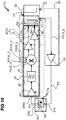
- FIG 6 an external view (of a housing) of a control device 60 is shown, with which the control of individual units of a drop detection device 11, 11a, 11b, the evaluation of measurement signals, the monitoring of the functionality of individual units and the setting and coordination of individual system parameters can be performed.
- the entire electronics are housed in this housing. In principle, this concerns the entire system of drop detection including the optoelectronic signal converter (receiver photodiode 32 and transmitter LED 31). These represent the limit to the “optical path”, ie the transmission optical waveguide L1, the emission window and the drop path T, which is external.
- the data bus connection DB will serve, among other things, for communication with the valve control unit. For example, the current status of the drop detection or statistics on the past dosing processes (number of detected errors and when they occurred) can be transmitted to them via this data bus connection DB.
- Another possible application for this data bus connection DB is that the drop detection could request the valve control unit via this bus to intentionally initiate incorrect metering in order to ensure correct functioning to check the drop detection. This would then have to reliably detect these intentional incorrect dosages.
- Part of the control device 60 is also a communication interface I / O, with which trigger signals are received from the valve control unit 70 and via which information on the system status of the drop detection device and the dosage status is output.
- the control device 60 also has an input RX, which serves as a connection between the receiving optical waveguide L2 and the photo element 32.
- An output TX is used to connect the transmission optical waveguide L1 to the transmission light-emitting diode 31.
- Another input U S is used to supply voltage to the control device 60.
- An additional input PGM can be used as a programming socket for firmware transfer.
- the control device 60 comprises two pressure switches S1, S2 for tuning individual units of a drop detection device. For example, by pressing the one switch S1 for a defined period of time (here for example 2 s), a first training mode, a "hardware training mode", is switched on in which, for example, a pulse width of the carrier signal TS is set so that an optimal Brightness of the light emitting unit 31 with respect to the residual light reaching the light sensor unit based on the light beam formed of the carrier signal TS is achieved, the setting of a frequency of the pulsed carrier signal TS so that the two sidebands of the modulated signal EMS can pass a filter unit 42 connected downstream of the sensor device, the setting of the phase position of the carrier signal TS via the signal PWM_5 in relation to the Control signals PWM_1, ..., PWM_4, with which the mixer unit 43 belonging to the demodulation unit is controlled, and the setting of the amplifier units 44 and 45 for voltage adjustment and the amplifier unit 41, which acts as a transimpedance amplifier, takes place.
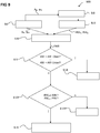
- FIG 8 is the operating principle 800 of the Figures 1 and 3 illustrated modulation value determination unit 51 of an evaluation unit 50 in detail.
- the modulation value determination unit 51 acquires in-phase and quadrature components I, Q from the in Figure 2 Inputs 53, 54 of the control unit 60 shown downstream of the AD converters of the evaluation unit 50.
- the sampling of the in-phase signal I and the quadrature signal Q takes place continuously.
- the two values I, Q are preferably obtained at the same time.
- the values I, Q pass through a median and mean value filter before they are further processed in order to remove extreme values caused by interference radiation, ADC conversion errors, etc.
- step 8.II the signal components I, Q are converted into a signal MOD (A, ⁇ ) with the aid of a polar coordinate transformation, which comprises information relating to the amplitude A and the phase ⁇ of the modulation signal MOD.
- a polar coordinate transformation which comprises information relating to the amplitude A and the phase ⁇ of the modulation signal MOD.
- I and Q correspond to the amplitudes of the in-phase and quadrature components I, Q of the demodulated signal and the modulation signal MOD, respectively.
- the amplitude A and the phase ⁇ are time-dependent quantities. Due to the high sampling rate and the associated rapid acquisition of values, the calculations according to equations 1 and 2 are carried out using look-up tables with linear inter-value interpolation.
- step 8.III the amplitude A and the phase ⁇ of the modulation signal MOD (A, ⁇ ) are derived over time.
- step 8.IV derivative values dA / dt, d ⁇ / dt are considered in a predetermined time interval I T and a predetermined number of maximum values of the derivative values dA / dt, d ⁇ / dt, for example the largest 10 values, in the time interval I T selected.
- the time interval I T can, for example, be specified in advance when the overall system is initialized or during the detection filter training.
- modulation values A M , ⁇ M for the amplitude A and the phase ⁇ are formed as a sum over the number of maximum values determined in advance.
- step 9.IV a deviation AW of the modulation values A M , ⁇ M determined by the modulation value determination unit 51 for the amplitude A and the phase ⁇ from the reference values RW A , RW ⁇ is calculated.
- step 9.V a comparison is made between the respectively determined deviation AW and a maximum permitted relative deviation upwards AW_Oben or downwards AW_Bottom. If the deviation is too great, which is what in Figure 9 is marked with "j", it is reported in step 9.VI that a faulty drop has been determined.
- the amount of the permitted deviation AW_Oben or AW_Bown is determined on the basis of one or more target drops during an initialization process or in the aforementioned software training mode of the drop detection device.
- the reference values RW A , RW ⁇ ie, for example, the mean values over the modulation values A M , von M of past drops are monitored.
- step 9.VII it is determined whether the reference values RW A , RW ⁇ for amplitude A and phase ⁇ are in a predetermined absolute value interval ARI, PRI.
- the capacitor 31a is positioned in such a way that a trajectory T of a drop TR, which was emitted by a metering valve DV, runs between the capacitor plates 31b, 31c of the capacitor 31a, perpendicular to the course of the field lines of the developing electric field.
- the coupling achieved between the transmitting and receiving branches is influenced. This coupling is dependent on the reactance X c of the capacitor 31a. Slight changes in the reactance X c of the capacitor 31a, which are caused by a drop TR flying through, lead to a modulation of the carrier signal TS.
- f is the frequency of the carrier signal TS applied to the capacitor 31a and C is the capacitance of the capacitor 31a.
- f is the frequency of the carrier signal TS applied to the capacitor 31a
- C is the capacitance of the capacitor 31a.
- ⁇ 0 stands for the dielectric constant
- ⁇ r for the permittivity of the capacitor 31a
- A for the area of the capacitor plates 31b, 31c and the parameter d for the distance between the capacitor plates 31b, 31c. Since the area A of the capacitor plates 31b, 31c and the distance d between the capacitor plates 31b, 31c are not changed, a change in the capacitance C and thus the reactance X c is only dependent on a change ⁇ r in the material-specific permittivity ⁇ r . If a drop TR enters the space between the two capacitor plates 31b, 31c, the permittivity ⁇ r in this area changes as a function of the dosage and the material of the drop.
- the modulation of the carrier signal TS thus results from the fluctuation in the permittivity ⁇ r caused by the drop.
- Optical waveguides are not necessary in this embodiment.
- the capacitor plates 31b, 31c must be positioned relatively close to the trajectory of the drop TR and thus to the outlet of the metering valve DV.
- the measurement signal MS possibly modulated by a drop TR, is transmitted as a modulated electrical measurement signal EMS from the modulation unit 30 to an evaluation unit 50.
- the embodiment shown has a demodulation unit 40 which also has essentially the same components with the same functions as the demodulation unit 40 in the embodiment according to FIG Figure 2 .
- the demodulation unit 40 thus has an amplifier unit 41 which amplifies the modulated electrical measurement signal EMS.
- the amplifier unit 41 serves to pre-amplify the modulated electrical measurement signal EMS detected by the modulation unit 30 and is controlled by a control signal output 22 of the signal generation unit 20. It is designed here as a normal voltage amplifier and not as a transimpedance amplifier as in the case of the optical detection variant.
- the demodulation unit 40 also comprises a filter unit 42.
- the filter unit 42 can, for example comprise a bandpass filter which only allows the two sidebands and the carrier frequency of the modulated electrical measurement signal EMS to pass.
- the filter unit 42 also removes any interference signals caused by interference fields which, for example, include frequencies that are far removed from the frequency of the carrier signal TS.
- the filter unit preferably a steep-edged bandpass filter, also removes harmonics generated by the pulse width modulation.
- the modulated electrical measurement signal EMS filtered in this way is then forwarded to a mixer 43, which mixes the modulated and filtered measurement signal EMS with the pulsed control signals PWM_1, ..., PWM_4 generated by the second signal generation unit 23 and out of phase with the carrier signal, and into an in-phase Signal amplifier 44 transmits an in-phase signal or an in-phase component I and a quadrature signal or a quadrature component Q is transmitted to a quadrature signal amplifier 45.
- the in-phase control of the mixer 43 results in the demodulation of only one sideband.
- the in-phase signal amplifier 44 and the quadrature signal amplifier 45 are controlled by a control signal output 22 of the signal generation unit 20.
- the amplifiers 41, 44, 45 are controlled separately from one another. They are set via a variable resistor (rheostat) that can be programmed via a data bus (eg I2C bus). Each rheostat (and thus amplifier) is adjusted individually.
- the setting of the amplifier 41 is completely independent of the amplifiers 44 and 45 in terms of value. However, the amplifiers 44 and 45 always have the same value in order not to change the relation between the I and Q signals. Nevertheless, these two are also controlled separately from each other.
- the control unit 60 comprises inputs 53, 54 for the signal components I, Q.
- the inputs 53, 54 are also followed by AD converters (not shown) which convert the analog signal components I, Q into digital signals.
- the amplifiers 44, 45 of the demodulation unit 40 can be adjusted in terms of their gain factor and are used to raise the signal components I, Q generated by the mixer unit 43 to a voltage level that is optimal for the AD converter. This ensures maximum utilization of the converter resolution.
- the evaluation unit also includes 50 also has a modulation value determination unit 51 and a detection filter unit 52.
- the evaluation unit 50 is in the in Figure 9 The exemplary embodiment shown is part of a control unit 60.
- the digitized signal components I, Q are mathematically processed in the modulation value determination unit 51 and transformed into amplitude and phase information, for example with the aid of polar coordinate transformation.
- the detection filter unit 52 can be designed, for example, as a parameterizable software filter with which it is determined on the basis of the recorded information whether a drop has passed the sensor system formed by the modulation unit 30a. Before the system 11a can start its regular operation, it must be set by two separate initialization processes. On the one hand, all hardware assemblies must be set to an optimal operating point for detection. These settings include the frequency adjustment of the carrier signal TS to the filter characteristic of the bandpass filter 42, the setting of the phase position of the mixer signals PWM_1 ...
- PWM_4 in relation to the carrier signal for precise sideband selection, the finding of the optimal gain factor of the transimpedance amplifier 41 and the signal adaptation of the I and Q Signals for the AD converter of the inputs 53, 54 through the ADC preamplifier 44, 45.
- all parameters of the detection filter unit 52 must be adjusted in relation to the expected target droplets TR. This includes the time window for searching for the derivation maxima for the amplitude and phase values, the permitted relative deviation ranges of the comparison values from the reference values of the amplitude and phase values and the permitted absolute ranges of the reference values of the amplitude and phase values. Both the hardware and the filter settings can be set manually or through automatic training processes
- unit is also intended to include components which consist of several, possibly also spatially separated, subunits.
- unit can also mean a conceptual logical unit, so that one and the same hardware component comprises several of these logical units can. This applies, for example, in particular to the modulation unit 30, the demodulation unit 40 and possibly also to the signal generation unit 20 and the evaluation unit 50.
Description
Die Erfindung betrifft eine Tropfendetektionseinrichtung. Zudem betrifft die Erfindung ein Verfahren zum Detektieren eines Tropfens eines Dosierventils, vorzugsweise eines Mikrodosierventils.The invention relates to a drop detection device. The invention also relates to a method for detecting a drop in a metering valve, preferably a microdosing valve.
Bei dem Aufbringen und Dosieren von dünnflüssigen oder pastösen Medien, beispielsweise bei dem Aufbringen von Klebstoffen, kommen Dosierventile zum Einsatz. Ein Dosierventil umfasst an der Stelle des Austritts des zu dosierenden Mediums eine Düse. Bei herkömmlichen Nadelventilen wird zum Dosieren einer definierten Medienmenge die Öffnung des Dosierventils freigegeben, indem die Dosiernadel aus dem Ventilsitz etwas herausgezogen wird. Dabei kann das Medium, beispielsweise unter Vordruck getrieben, die Düsenöffnung bzw. Ventilöffnung durchströmen. Wenn der Befüllvorgang oder der Dosiervorgang abgeschlossen werden soll, wird die Düse des Dosierventils geschlossen.When applying and metering thin or pasty media, for example when applying adhesives, metering valves are used. A metering valve comprises a nozzle at the point where the medium to be metered exits. In conventional needle valves, the opening of the metering valve is released for metering a defined amount of media by pulling the metering needle out of the valve seat a little. In this case, the medium can flow through the nozzle opening or valve opening, for example driven under pre-pressure. When the filling process or the dosing process is to be completed, the nozzle of the dosing valve is closed.
Insbesondere basierend auf der Piezodosierventiltechnik lassen sich auch sogenannte "Jet-Ventile" aufbauen. Hierbei erfolgt die Abgabe von Medienmengen durch die Hin- und Herbewegung der Dosiernadel bzw. eines Ventilstößels, wobei eine Medienmenge bei einer Bewegung der Dosiernadel bzw. des Ventilstößels in Richtung der Düsenöffnung aus dieser strahlartig herausgestoßen wird. Dies erlaubt ein Aufbringen von definierten Mengen des Dosiermediums auch über größere Distanzen zwischen Dosierventil und Auftragsfläche, z. B. auf einem zu bearbeitenden Bauteil. Die Dosierabstände können dabei je nach Einsatzgebiet zwischen einem halben Millimeter und wenigen Millimetern variieren. Jet-Ventile ermöglichen eine sehr feine Dosierung mit hoher Geschwindigkeit bei vollständiger Kontaktlosigkeit zu dem zu bearbeitenden Bauteil. Um die Abgabe einzelner Tropfen kontrollieren zu können, sind Sensoren zur Detektion der Tropfen und entsprechende Auswertungsprozesse nötig.So-called “jet valves” can also be constructed, in particular based on piezo metering valve technology. The dispensing of media quantities takes place through the back and forth movement of the metering needle or a valve tappet, with a media quantity being ejected like a jet when the metering needle or valve tappet moves in the direction of the nozzle opening. This allows defined quantities of the dosing medium to be applied even over greater distances between the dosing valve and the application surface, e.g. B. on a component to be machined. The dosing distances can vary between half a millimeter and a few millimeters depending on the application. Jet valves enable very fine dosing at high speed with no contact with the component to be processed. In order to be able to control the delivery of individual drops, sensors for detecting the drops and corresponding evaluation processes are necessary.
Bei der optischen Detektion von Tropfen, welche insbesondere zuvor durch ein Jet-Ventil erzeugt wurden, treten folgende Schwierigkeiten auf:
Zunächst einmal soll zwischen dem Dosierventil und einer mit dem Tropfen beaufschlagten Oberfläche eines zu bearbeitenden Bauelements ein möglichst geringer Abstand eingehalten werden. Dieser Abstand kann je nach Anwendungsfall zwischen 0,5 mm und 3 mm variieren. Durch diese Vorgabe wird die mögliche Bauhöhe eines Tropfensensors stark eingeschränkt. Weiterhin sind die zu detektierenden Tropfen mit Durchmessern von manchmal weniger als 10 µm sehr klein. Ferner ist die Geschwindigkeit der Tropfen mit bis zu 50 m/s sehr hoch, wodurch sich eine extrem kurze Durchflugszeit durch einen von einem detektierenden Sensor überwachten Bereich von einigen Mikrosekunden ergibt. Die geringe Größe und hohe Geschwindigkeit des Tropfens bedingen ein schwaches Sensorsignal mit geringen Signalamplituden und einem ungünstigen Signal-RauschVerhältnis, was eine störungssichere optische Detektion eines Tropfens sehr erschwert. Versucht man einen optoelektronischen Sensor, wie zum Beispiel einen Fotodetektor, nahe an der Düse des Ventils anzubringen, um ein möglichst starkes optisches und damit nach der Wandlung elektrisches Signal zu erhalten, so kommt man mit den geringen Abmessungen des Systems in Konflikt. Beispielsweise ist es aufgrund des geringen Platzangebots kaum möglich, die gesamte Auswerteelektronik direkt am Sensor zu positionieren. Wird die Auswerteelektronik jedoch entfernt von der Sensorik angeordnet, so besteht das Problem, dass das erfasste elektrische analoge Signal zu der Auswerteelektronik störungssicher übertragen werden muss.The following difficulties arise in the optical detection of droplets, which were generated in particular by a jet valve:
First of all, the smallest possible distance should be maintained between the metering valve and a surface of a component to be processed on which the drop is applied. This distance can vary between 0.5 mm and 3 mm depending on the application. The possible overall height of a drop sensor is determined by this specification highly limited. Furthermore, the droplets to be detected are very small, sometimes with diameters of less than 10 µm. Furthermore, the speed of the droplets is very high at up to 50 m / s, which results in an extremely short flight time of a few microseconds through an area monitored by a detecting sensor. The small size and high speed of the drop result in a weak sensor signal with low signal amplitudes and an unfavorable signal-to-noise ratio, which makes a fail-safe optical detection of a drop very difficult. If you try to attach an optoelectronic sensor, such as a photodetector, close to the nozzle of the valve in order to obtain the strongest possible optical and thus electrical signal after the conversion, you come into conflict with the small dimensions of the system. For example, due to the small amount of space available, it is hardly possible to position the entire evaluation electronics directly on the sensor. However, if the evaluation electronics are arranged remotely from the sensor system, the problem arises that the recorded electrical analog signal must be transmitted to the evaluation electronics in a fail-safe manner.
In
In
In
In
In
In
Es ist daher eine Aufgabe der vorliegenden Erfindung, eine an die beengten Platzverhältnisse angepasste Tropfendetektionseinrichtung zu entwickeln, welche hochsensitiv und störungssicher arbeitet.It is therefore an object of the present invention to develop a drop detection device which is adapted to the restricted space conditions and which operates in a highly sensitive and fail-safe manner.
Diese Aufgabe wird durch eine Tropfendetektionseinrichtung nach Anspruch 1 und ein Verfahren zum Detektieren eines Tropfens eines Dosierventils gemäß Patentanspruch 15 gelöst.This object is achieved by a drop detection device according to
Eine erfindungsgemäße Tropfendetektionseinrichtung zur Detektion von aus einer Düse eines Dosierventils austretenden Tropfen weist eine Signalerzeugungseinheit auf, welche dazu eingerichtet ist, ein Trägersignal mit einer definierten Pulsfrequenz zu erzeugen. Als Trägersignal soll ein gepulstes Signal verstanden werden, welches sich mit konstanten charakteristischen Parametern (z. B. Frequenz, also der Pulsfrequenz oder auch Trägerfrequenz genannt, Amplitude) periodisch ändert, beispielsweise in einem bestimmten Rhythmus an- und abgeschaltet wird. Das Signal trägt zunächst im unmodulierten Zustand außer den konstanten charakteristischen Parametern keine Information mit sich. Die zu übertragende Information erhält es erst durch die Modulation, welche durch irgendeine Art von physikalischer Wechselwirkung des Trägersignals mit einer Informationsquelle realisiert sein kann. Beispielsweise kann ein Trägersignal mit Hilfe eines Modulationssignals moduliert werden oder durch eine sonstige physikalische Störung beeinflusst werden, z. B. einen zu detektierenden Tropfen. Als Modulation soll in diesem Zusammenhang eine Änderung des Trägersignals bezüglich einer oder mehrerer seiner Parameter, wie zum Beispiel der Amplitude, der Frequenz oder der Phase, verstanden werden. Die Pulsfrequenz bzw. Trägerfrequenz sollte höher als die Frequenz der Modulation sein bzw. die Wellenlänge sollte kürzer sein als eine durch einen Tropfen verursachte "Störung" des Signals.A drop detection device according to the invention for the detection of drops emerging from a nozzle of a metering valve has a signal generating unit which is set up to generate a carrier signal with a defined pulse frequency. A carrier signal is to be understood as a pulsed signal which changes periodically with constant characteristic parameters (e.g. frequency, i.e. the pulse frequency or also called carrier frequency, amplitude), for example, is switched on and off in a certain rhythm. In the unmodulated state, the signal initially carries no information with it apart from the constant characteristic parameters. It only receives the information to be transmitted through the modulation, which can be implemented by any kind of physical interaction between the carrier signal and an information source. For example, a carrier signal can be modulated with the aid of a modulation signal or influenced by some other physical disturbance, e.g. B. a drop to be detected. In this context, modulation should be understood to mean a change in the carrier signal with regard to one or more of its parameters, such as, for example, the amplitude, the frequency or the phase. The pulse frequency or carrier frequency should be higher than the frequency of the modulation or the wavelength should be shorter than a "disturbance" of the signal caused by a drop.
Zudem umfasst die erfindungsgemäße Tropfendetektionseinrichtung eine Modulationseinheit, welche dazu eingerichtet ist, ein durch eine physikalische Wechselwirkung des Trägersignals mit einem zu detektierenden Tropfen moduliertes Messsignal zu erzeugen. Teil der erfindungsgemäßen Tropfendetektionseinrichtung ist auch eine Demodulationseinheit, die dazu eingerichtet ist, eine Quadraturdemodulation des Messsignals durchzuführen, um eine In-Phase-Komponente und eine Quadratur-Komponente des demodulierten Messsignals zu ermitteln. Überdies weist die erfindungsgemäße Tropfendetektionseinrichtung eine Auswertungseinheit auf, welche dazu eingerichtet ist, auf Basis des modulierten Messsignals unter Berücksichtigung der definierten Pulsfrequenz zu ermitteln, ob ein Tropfen von dem Dosierventil abgegeben wurde. Vorzugsweise kann hierzu in einer Demodulationseinheit, welche zum Beispiel Teil der Auswertungseinheit sein kann, unter Berücksichtigung der definierten Pulsfrequenz ein Modulationssignal auf Basis des modulierten Signals ermittelt werden, und auf Basis des Modulationssignals wird dann ermittelt, ob ein Tropfen von dem Dosierventil abgegeben wurde. Als Modulationssignal soll in diesem Zusammenhang ein der Modulation des Trägersignals durch den Tropfen entsprechendes Signal verstanden werden, das durch Demodulation von dem Trägersignal wieder "getrennt" werden kann. Das Trägersignal wird von der Signalerzeugungseinheit vorzugsweise mit einer definierten Pulsfrequenz und einem für die Modulationseinheit optimalen Tastverhältnis erzeugt. Auf das Trägersignal abgestimmt bzw. davon abgeleitet können von der Signalerzeugungseinheit vorzugsweise weitere Steuersignale, wie zum Beispiel Steuersignale eines Mischers der Demodulationseinheit mit einer optimalen Phasenlage zur Seitenbandselektion, erzeugt werden.In addition, the drop detection device according to the invention comprises a modulation unit which is designed to generate a measurement signal modulated by a physical interaction of the carrier signal with a drop to be detected. Part of the drop detection device according to the invention is also a demodulation unit which is set up to carry out quadrature demodulation of the measurement signal in order to determine an in-phase component and a quadrature component of the demodulated measurement signal. In addition, the drop detection device according to the invention has an evaluation unit which is set up to determine on the basis of the modulated measurement signal, taking into account the defined pulse frequency, whether a drop has been dispensed by the metering valve. For this purpose, a modulation signal based on the modulated signal can preferably be determined in a demodulation unit, which can be part of the evaluation unit, for example, taking into account the defined pulse frequency, and based on the modulation signal it is then determined whether a drop has been dispensed by the metering valve. In this context, a modulation signal is to be understood as a signal which corresponds to the modulation of the carrier signal by the drop and which can be "separated" again from the carrier signal by demodulation. The carrier signal is generated by the signal generation unit, preferably with a defined pulse frequency and a pulse duty factor that is optimal for the modulation unit. Further control signals, such as, for example, control signals of a mixer of the demodulation unit with an optimal phase position for sideband selection, can preferably be generated by the signal generation unit, matched to or derived from the carrier signal.
Bestimmte Signalparameterwerte des modulierten Messsignals bzw. des Modulationssignals, wie zum Beispiel der Verlauf der Kurve der zeitlichen Abhängigkeit von Amplitude und Phase des Modulationssignals, entsprechen bestimmten Eigenschaften bzw. Abmessungen eines zu detektierenden Tropfens. Die Beziehung zwischen den genannten Signalparametern und den Eigenschaften bzw. Abmessungen eines zu detektierenden Tropfens müssen für die Detektion nicht unmittelbar bekannt sein. Es reicht aus, wenn vorab, beispielsweise in einem Trainingsverfahren mit Hilfe von "Muster-Tropfen" mit definierten Abmessungen, festgelegt wurde, welche Signalparameterwerte des modulierten Messsignals bzw. des Modulationssignals auf einen Tropfen mit den gewünschten Eigenschaften bzw. Abmessungen (der im Trainingsverfahren genutzten "Muster-Tropfen") hinweisen, d. h. wann ein Tropfen als detektiert gilt. Relevante Einstellparameter können zum Beispiel durch die automatisierte Beobachtung von in einem Trainingsprozess detektierten Soll-Tropfen gefunden werden.Certain signal parameter values of the modulated measurement signal or the modulation signal, such as the course of the curve of the time dependency of the amplitude and phase of the modulation signal, correspond to certain properties or dimensions of a drop to be detected. The relationship between the signal parameters mentioned and the properties or dimensions of a drop to be detected do not have to be known directly for detection. It is sufficient if it was determined in advance, for example in a training process with the aid of "sample drops" with defined dimensions, which signal parameter values of the modulated measurement signal or the modulation signal apply to a drop with the desired properties or dimensions (those used in the training process "Sample drop"), ie when a drop is considered to be detected. Relevant setting parameters can be found, for example, through the automated observation of target drops detected in a training process.
Bei einem erfindungsgemäßen Verfahren zum Detektieren eines Tropfens eines Dosierventils, für welche die erfindungsgemäße Tropfendetektionseinrichtung bereitgestellt wird, wird ein vorzugsweise gepulstes Trägersignal mit einer definierten Pulsfrequenz erzeugt. Durch Beaufschlagen einer Trajektorie, auf der sich ein möglicher Tropfen bewegt, welcher von dem Dosierventil abgegeben wird, wird dafür gesorgt, dass durch eine physikalische Wechselwirkung des Trägersignals mit einem zu detektierenden Tropfen, der von dem Dosierventil abgegeben wurde, ein moduliertes Messsignal erzeugt wird. Dieses Messsignal entspricht, wenn kein Tropfen abgegeben wird, im Wesentlichen dem unveränderten Trägersignal und ansonsten dem durch die "Störung" des Tropfens modifizierten Trägersignal. Es wird eine Quadraturdemodulation des Messsignals durchgeführt, um eine In-Phase-Komponente und eine Quadratur-Komponente des demodulierten Messsignals zu ermitteln. Das Messsignal wird analysiert, und auf Basis des modulierten Messsignals wird unter Berücksichtigung der definierten Pulsfrequenz, vorzugsweise indem zunächst auf Basis des modulierten Messsignals ein Modulationssignal für die weitere Auswertung erzeugt wird, ermittelt, ob ein Tropfen von dem Dosierventil abgegeben wurde.In a method according to the invention for detecting a drop of a metering valve, for which the drop detection device according to the invention is provided, a preferably pulsed carrier signal with a defined pulse frequency is generated. By applying a trajectory on which a possible drop that is dispensed by the metering valve moves, it is ensured that a modulated measurement signal is generated through a physical interaction of the carrier signal with a drop to be detected that was dispensed by the metering valve. If no drop is dispensed, this measurement signal corresponds essentially to the unchanged carrier signal and otherwise to the carrier signal modified by the “disturbance” of the drop. A quadrature demodulation of the measurement signal is carried out in order to determine an in-phase component and a quadrature component of the demodulated measurement signal. The measurement signal is analyzed and, on the basis of the modulated measurement signal, taking into account the defined pulse frequency, preferably by initially generating a modulation signal for further evaluation on the basis of the modulated measurement signal, it is determined whether a drop has been dispensed by the metering valve.
Weitere besonders vorteilhafte Ausgestaltungen und Weiterbildungen der Erfindung ergeben sich aus den abhängigen Ansprüchen sowie der nachfolgenden Beschreibung, wobei die Patentansprüche einer bestimmten Kategorie auch gemäß den abhängigen Ansprüchen einer anderen Kategorie weitergebildet sein können und Merkmale verschiedener Ausführungsbeispiele zu neuen Ausführungsbeispielen kombiniert werden können.Further particularly advantageous configurations and developments of the invention emerge from the dependent claims and the following description, whereby the patent claims of a certain category can also be developed according to the dependent claims of another category and features of different embodiments can be combined to form new embodiments.
In einer Ausgestaltung der Tropfendetektionseinrichtung wird eine Abgabe eines Tropfens in einem definierten Zeitfenster überprüft, welches mit einer Tropfenabgabesteuerung des Dosierventils synchronisiert ist. Anders ausgedrückt, wird ein Zeitfenster, in dem ein Tropfen detektiert bzw. nach einem Tropfen überhaupt "gesucht" wird oder gegebenenfalls überhaupt ein Trägersignal abgegeben wird, mit einer Tropfenabgabe des Dosierventils so synchronisiert, dass die vorgesehene Tropfenabgabe innerhalb des Zeitfensters liegt.In one embodiment of the drop detection device, the dispensing of a drop is checked in a defined time window which is synchronized with a drop dispensing control of the metering valve. In other words, a time window in which a drop is detected or "searched" for a drop at all or, if necessary, a carrier signal is output at all, is synchronized with a drop discharge of the metering valve so that the intended drop discharge is within the time window.
In einer speziellen Ausgestaltung umfasst die Tropfendetektionseinrichtung eine Demodulationseinheit, die dazu eingerichtet ist, eine Amplitudendemodulation des Messsignals durchzuführen.In a special embodiment, the drop detection device comprises a demodulation unit which is set up to perform an amplitude demodulation of the measurement signal.
Vorzugsweise können auf Basis der In-Phase-Komponente und der Quadratur-Komponente der Betrag der Amplitude und/oder die Phase eines auf dem modulierten Messsignal basierenden Modulationssignals ermittelt werden. Beispielsweise lassen sich Amplitude und Phase des Modulationssignals durch Polarkoordinatentransformation der In-Phase-Komponente und der Quadratur-Komponente gewinnen. Hierzu kann die Auswertungseinheit der Tropfendetektionseinrichtung bevorzugt eine Modulationswertermittlungseinheit aufweisen, welche dazu eingerichtet ist.The magnitude of the amplitude and / or the phase of a modulation signal based on the modulated measurement signal can preferably be determined on the basis of the in-phase component and the quadrature component. For example, the amplitude and phase of the modulation signal can be obtained by transforming the polar coordinates of the in-phase component and the quadrature component. For this purpose, the evaluation unit of the drop detection device can preferably have a modulation value determination unit which is set up for this purpose.
In einer speziellen Variante der Tropfendetektionseinrichtung ist diese, insbesondere die Modulationswertermittlungseinheit, dazu eingerichtet, Amplituden-Ableitungswerte, umfassend die zeitliche Ableitung des Betrags der Amplitude, und/oder Phasen-Ableitungswerte, umfassend die zeitliche Ableitung der Phase des Modulationssignals, zu ermitteln.In a special variant of the drop detection device, this, in particular the modulation value determination unit, is set up to determine amplitude derivative values, including the time derivative of the magnitude of the amplitude, and / or phase derivative values, including the time derivative of the phase of the modulation signal.
In einer bevorzugten Ausgestaltung ist die Tropfendetektionseinrichtung, insbesondere die Modulationswertermittlungseinheit, dazu eingerichtet, in einem vorbestimmten festen Zeit-Intervall des Zeitfensters eine vorbestimmte Anzahl der Amplituden-Ableitungswerte zu Amplituden-Vergleichswerten und/oder in einem vorbestimmten zweiten Zeit-Intervall des Zeitfensters eine vorbestimmte Anzahl der Phasen-Ableitungswerte zu Phasen-Vergleichswerten zu kombinieren. Beispielsweise kann die Kombination der Amplituden-Ableitungswerte und der Phasen-Ableitungswerte eine Summation bzw. Addition mehrerer Amplituden-Ableitungswerte zu Amplituden-Vergleichswerten und eine Summation bzw. Addition mehrerer Phasen-Ableitungswerte zu Phasen-Vergleichswerten umfassen. Prinzipiell werden die beiden Zeit-Intervalle für die Kombination der Amplituden-Ableitungswerte und die Kombination der Phasen-Ableitungswerte während der Trainingsphase bzw. bei dem oben genannten Trainingsverfahren festgelegt. Dabei werden während des Trainings der Zeit-Intervalle ständig Werte ohne zeitliche Beschränkung gewonnen. Die Zeit-Intervalle werden so festgelegt, dass eine definierte Anzahl von Maximalwerten für die Amplituden-Ableitungswerte und die Phasen-Ableitungswerte in diesen Zeit-Intervallen gewonnen werden können. Die Zeit-Intervalle für die Amplituden-Ableitungswerte und die Phasen-Ableitungswerte werden vorzugsweise unabhängig voneinander festgelegt. D. h., deren Zeitdauer und deren Startzeitpunkt sind unabhängig voneinander.In a preferred embodiment, the drop detection device, in particular the modulation value determination unit, is set up to convert a predetermined number of the amplitude derivative values to amplitude comparison values in a predetermined fixed time interval of the time window and / or a predetermined number in a predetermined second time interval of the time window to combine the phase derivative values into phase comparison values. For example, the combination of the amplitude derivative values and the phase derivative values can include a summation or addition of several amplitude derivative values to form amplitude comparison values and a summation or addition of several phase derivative values to form phase comparison values. In principle, the two time intervals for the combination of the amplitude derivative values and the combination of the phase derivative values are established during the training phase or in the case of the training method mentioned above. Values are continuously obtained during the training of the time intervals without any time limit. The time intervals are set in such a way that a defined number of maximum values can be obtained for the amplitude derivative values and the phase derivative values in these time intervals. The time intervals for the amplitude derivative values and the phase derivative values are preferably established independently of one another. In other words, their duration and their start time are independent of one another.
Beispielsweise kann ein Zeit-Intervall so liegen, dass es 50 Messwerte umfasst, sollte die definierte Anzahl von Maximalwerten, zum Beispiel 10, in einem solch großen Bereich liegen. Nach Festlegung auf diesen Bereich, also nach der Trainingsphase, werden dann immer die 10 Maxima aus diesem 50 Messwerte umfassenden Zeit-Intervall ermittelt bzw. gesucht und weiterverwendet.For example, a time interval can be such that it comprises 50 measured values, should the defined number of maximum values, for example 10, be in such a large range lie. After setting this area, that is, after the training phase, the 10 maxima are then always determined or searched for and used from this time interval comprising 50 measured values.
Auf Basis der Amplituden-Vergleichswerte und/oder der Phasen-Vergleichswerte kann dann bevorzugt ermittelt werden, ob das Modulationssignal einen Tropfen indiziert. Zusätzlich zu der Modulationswertermittlungseinheit umfasst daher die Auswertungseinrichtung der erfindungsgemäßen Tropfendetektionseinrichtung bevorzugt eine Detektionsfiltereinheit, welche dazu eingerichtet ist, auf Basis der Amplituden-Vergleichswerte und/oder der Phasen-Vergleichswerte zu ermitteln, ob das Modulationssignal einen Tropfen indiziert.On the basis of the amplitude comparison values and / or the phase comparison values, it can then preferably be determined whether the modulation signal indicates a drop. In addition to the modulation value determination unit, the evaluation device of the drop detection device according to the invention therefore preferably comprises a detection filter unit which is set up to determine on the basis of the amplitude comparison values and / or the phase comparison values whether the modulation signal indicates a drop.
Zur Detektion eines Tropfens kann insbesondere die Detektionsfiltereinheit der Tropfendetektionseinrichtung dazu eingerichtet sein, eine Abweichung eines, z. B. von der Modulationswertermittlungseinheit, ermittelten Amplituden-Vergleichswerts von einem Amplituden-Referenzwert zu ermitteln und/oder eine Abweichung eines, z. B. von der Modulationswertermittlungseinheit, ermittelten Phasen-Vergleichswerts von einem Phasen-Referenzwert zu ermitteln. Ein Amplituden-Referenzwert kann zum Beispiel aus einer Mehrzahl von Amplituden-Vergleichswerten von vorher erfassten Modulationssignalen gebildet sein. Ein Phasen-Referenzwert kann zum Beispiel aus einer Mehrzahl von Phasen-Vergleichswerten von vorher erfassten Modulationssignalen gebildet sein. Bei der Bildung der Referenzwerte sollte darauf geachtet werden, dass nur Vergleichswerte, welche als korrekt detektierten Tropfen zugeordnet sind, in die Ermittlung der Referenzwerte eingehen.In order to detect a drop, in particular the detection filter unit of the drop detection device can be set up to detect a deviation in a e.g. B. from the modulation value determination unit, determined amplitude comparison value from an amplitude reference value to determine and / or a deviation of, z. B. from the modulation value determination unit to determine determined phase comparison value from a phase reference value. An amplitude reference value can be formed, for example, from a plurality of amplitude comparison values from previously acquired modulation signals. A phase reference value can be formed, for example, from a plurality of phase comparison values from previously acquired modulation signals. When creating the reference values, care should be taken to ensure that only comparison values that are assigned as correctly detected drops are included in the determination of the reference values.
In einer speziellen Ausgestaltung kann die Tropfendetektionseinrichtung eine Referenzwert-Speichereinrichtung aufweisen, in der ein Amplituden-Referenzwert, welcher aus einer Mehrzahl von Amplituden-Vergleichswerten von vorher erfassten Modulationssignalen gebildet ist und/oder ein Phasen-Referenzwert, welcher aus einer Mehrzahl von Phasen-Vergleichswerten von vorher erfassten Modulationssignalen gebildet ist, als variable Referenzwerte gespeichert sind. Hieraus resultiert eine ständige Anpassung des Referenzwertes bei einer - in Bezug auf die Vergleichswerte eines Einzeltropfens - langsamen globalen durchschnittlichen Schwankung der Vergleichswerte. Gegenüber dem Vergleich der Vergleichswerte mit einer absoluten Größe können hierdurch die erlaubten Schwankungsbreiten in Bezug auf die Referenzwerte verkleinert werden.In a special embodiment, the drop detection device can have a reference value storage device in which an amplitude reference value, which is formed from a plurality of amplitude comparison values from previously acquired modulation signals and / or a phase reference value, which is composed of a plurality of phase comparison values is formed by previously detected modulation signals, are stored as variable reference values. This results in a constant adjustment of the reference value in the case of a slow global average fluctuation of the comparison values in relation to the comparison values of a single drop. Compared to the comparison of the comparison values with an absolute variable, this allows the permitted fluctuation ranges to be reduced in relation to the reference values.
Zur Ermittlung, ob ein Tropfen detektiert wurde, kann die Tropfendetektionseinrichtung, insbesondere die Detektionsfiltereinheit, dazu eingerichtet sein, zu ermitteln, ob die ermittelte Abweichung des Amplituden-Vergleichswerts vom Amplituden-Referenzwert und/oder die ermittelte Abweichung des Phasen-Vergleichswerts vom Phasen-Referenzwert einen Maximalwert nicht überschreiten. Die Referenzwerte werden während des normalen Detektionsvorgangs laufend neu gewonnen. Sie stellen in Verbindung mit den aus einer Filtertrainingsphase ermittelten erlaubten relativen Abweichungen eine Art Sollwert dar. Die erlaubten relativen Abweichungsbreiten stellen empirische Größen dar, da sie bei dem Filtertraining ermittelt werden. Liegen die ermittelten Vergleichswerte zu weit weg von dem Sollwert, so wird daraus geschlossen, dass entweder kein Tropfen oder zumindest kein regulärer Tropfen detektiert wurde.To determine whether a drop has been detected, the drop detection device, in particular the detection filter unit, can be set up to determine whether the determined deviation of the amplitude comparison value from the amplitude reference value and / or the determined deviation of the phase comparison value from the phase reference value do not exceed a maximum value. The reference values are continuously acquired anew during the normal detection process. In connection with the permitted relative deviations determined from a filter training phase, they represent a kind of nominal value. The permitted relative deviation widths represent empirical values, since they are determined during the filter training. If the comparison values determined are too far away from the target value, it is concluded from this that either no drop or at least no regular drop was detected.
In einer besonders bevorzugten Variante wird ermittelt, ob der für die Ermittlung der Abweichung des Amplituden-Vergleichswerts verwendete Amplituden-Referenzwert in einem vorbestimmten Amplituden-Referenzwertintervall liegt und/oder ob der für die Ermittlung der Abweichung des Phasen-Vergleichswerts verwendete Phasen-Referenzwert in einem vorbestimmten Phasen-Referenzwertintervall liegt. Hierzu kann wiederum die Detektionsfiltereinheit entsprechend eingerichtet sein. Beispielsweise kann in einer Referenzwert-Speichereinrichtung jeweils ein festes Referenzwertintervall für die Amplituden- und Phasenreferenzwerte gespeichert sein. Ein solches festes Referenzwertintervall kann beispielsweise in einer Trainingsphase ermittelt werden, in der auch eine mögliche Schwankungsbreite eines Referenzwerts gemessen wird. Liegt der verwendete Referenzwert nicht in dem festen Referenzwertintervall, so wird davon ausgegangen, dass zur Festlegung des Referenzwertes überwiegend nicht reguläre Tropfen beigetragen haben, so dass ein solcher Referenzwert als nicht mehr sicher zu betrachten ist. Beispielsweise kann in einem solchen Fall ein Ermittlungsergebnis als zumindest unsicher eingestuft oder gar verworfen werden. Eine solche Situation kann auftreten, wenn sich die Ausmaße der von einem Dosierventil dosierten Tropfen nur langsam, aber stetig ändern. Wird nun ein Referenzwert auf Basis solcher geänderter Modulationswerte bzw. Vergleichswerte gebildet, so kann im ungünstigen Fall ein Referenzwert auch einem nicht korrekten Tropfen entsprechen, der von einem vorab ermittelten Soll-Tropfen zu stark abweicht. Um einen solchen Fehler zu vermeiden, wird bevorzugt ein festes Intervall für die Referenzwerte festgelegt, von dem diese nicht abweichen dürfen. Wird ermittelt, dass die Referenzwerte nicht mehr in dem vorbestimmten Intervall liegen, so kann zum Beispiel eine Meldung an den Benutzer der Tropfendetektionseinrichtung ausgegeben werden, dass das System nicht mehr korrekt kalibriert ist. Der Benutzer kann dann Gegenmaßnahmen ergreifen. Beispielsweise kann der Benutzer das Dosierventil auf korrekte Funktion überprüfen und eventuelle Funktionsstörungen beseitigen. Anschließend können zum Beispiel nach einem Neustart des Systems korrekte Referenzwerte ermittelt werden. Die Referenzwerte werden in diesem Fall nach dem Neustart in einer Art Vorlaufphase ermittelt und während des Messvorgangs durch Mittelwertbildung von aktuellen Messwerten mit bisherigen Referenzwerten ständig aktualisiert.In a particularly preferred variant, it is determined whether the amplitude reference value used to determine the deviation of the amplitude comparison value is in a predetermined amplitude reference value interval and / or whether the phase reference value used to determine the deviation of the phase comparison value is in a predetermined phase reference value interval lies. The detection filter unit can again be set up accordingly for this purpose. For example, a fixed reference value interval for the amplitude and phase reference values can be stored in a reference value storage device. Such a fixed reference value interval can be determined, for example, in a training phase in which a possible fluctuation range of a reference value is also measured. If the reference value used does not lie within the fixed reference value interval, it is assumed that predominantly non-regular drops contributed to the establishment of the reference value, so that such a reference value can no longer be regarded as safe. For example, in such a case, a determination result can be classified as at least uncertain or even rejected. Such a situation can occur when the dimensions of the drops dosed by a metering valve change only slowly but steadily. If a reference value is now formed on the basis of such changed modulation values or comparison values, in the worst case a reference value can also correspond to an incorrect drop which deviates too much from a previously determined target drop. In order to avoid such an error, a fixed interval is preferably established for the reference values, from which they must not deviate. If it is determined that the reference values are no longer in the predetermined interval, then, for example, a message can be output to the user of the drop detection device that the system is no longer correctly calibrated. The user can then take countermeasures. For example, the user can check the metering valve for correct function and eliminate any malfunctions. Subsequently, correct reference values can be determined after a restart of the system, for example. In this case, the reference values are determined after the restart in a kind of lead-in phase and are continuously updated during the measurement process by averaging current measurement values with previous reference values.
In einer besonders praktikablen Ausgestaltung der erfindungsgemäßen Tropfendetektionseinrichtung umfasst die Modulationseinheit eine Lichtemissionseinheit und eine Lichtsensoreinheit. Als Lichtemissionseinheit kann zum Beispiel eine Leuchtdiode, insbesondere eine Halbleiterdiode, verwendet werden, welche ein elektrisches Trägersignal in ein Lichtsignal wandelt. Die Lichtsensoreinheit kann zum Beispiel einen auf dem Fotoeffekt beruhenden Sensor, vorzugsweise einen Halbleitersensor, umfassen.In a particularly practical embodiment of the drop detection device according to the invention, the modulation unit comprises a light emission unit and a light sensor unit. A light-emitting diode, in particular a semiconductor diode, which converts an electrical carrier signal into a light signal, can be used as the light-emitting unit. The light sensor unit can for example comprise a sensor based on the photo effect, preferably a semiconductor sensor.
Zusätzlich kann die Modulationseinheit der erfindungsgemäßen Tropfendetektionseinrichtung mindestens zwei Lichtleiter umfassen. Diese Lichtleiter sind bevorzugt mit der Lichtemissionseinheit und der Lichtsensoreinheit derart verbunden und derart positioniert, dass von der Lichtemissionseinheit emittiertes Licht zu einer Trajektorie eines von einem Dosierventil emittierten Tropfens geleitet wird, die Trajektorie des Tropfens kreuzt und der Lichtsensoreinheit zugeführt wird. Anders ausgedrückt, führt einer der beiden Lichtleiter das von der Lichtemissionseinheit erzeugte Licht zu einem Bereich, durch den erwartungsgemäß ein von einem Dosierventil emittierter Tropfen hindurchfliegt. Der andere Lichtleiter wird bevorzugt dem ersten Lichtleiter gegenüberliegend positioniert, so dass er das von einem Tropfen eventuell modulierte Licht aufnimmt und der Lichtsensoreinheit zuführt. Bei der Verwendung zweier Lichtleiter als Lichttransporteinheiten kann vorteilhaft auf die Anordnung der Lichtemissionseinheit und der Lichtsensoreinheit direkt im Bereich der Trajektorie des Tropfens verzichtet werden. Somit muss bei der Dimensionierung der Lichtemissionseinheit und der Lichtsensoreinheit nicht auf die üblicherweise sehr eingeschränkten räumlichen Verhältnisse im Bereich der Düse des Dosierventils bzw. zwischen Dosierventil und Werkstück Rücksicht genommen werden.In addition, the modulation unit of the drop detection device according to the invention can comprise at least two light guides. These light guides are preferably connected to the light emission unit and the light sensor unit and positioned in such a way that light emitted by the light emission unit is guided to a trajectory of a drop emitted by a metering valve, crosses the trajectory of the drop and is fed to the light sensor unit. In other words, one of the two light guides guides the light generated by the light emission unit to an area through which a drop emitted by a metering valve is expected to fly. The other light guide is preferably positioned opposite the first light guide, so that it picks up the light possibly modulated by a drop and feeds it to the light sensor unit. When using two light guides as light transport units, it is advantageous to dispense with the arrangement of the light emission unit and the light sensor unit directly in the area of the trajectory of the drop. Thus, when dimensioning the light emission unit and the light sensor unit, the usually very limited spatial relationships in the area of the nozzle of the metering valve or between the metering valve and the workpiece need not be taken into account.
Alternativ oder zusätzlich kann die erfindungsgemäße Tropfendetektionseinrichtung auch eine Modulationseinheit mit einer kapazitiven Sensoreinheit umfassen. In diesem Fall kann also das Prinzip der Tropfendetektion auf der Modulation der Kapazität eines Kondensators basieren, welche durch eine durch einen Tropfenflug bedingte Schwankung der relativen Permittivität hervorgerufen wurde. Die Analyse und Auswertung des modulierten Signals sowie die Erzeugung eines elektrischen Trägersignals können bei dieser Ausgestaltung analog zu den anderen Ausgestaltungen vorgenommen werden.As an alternative or in addition, the drop detection device according to the invention can also include a modulation unit with a capacitive sensor unit. In this case, the principle of drop detection can be based on the modulation of the capacitance of a capacitor, which was caused by a fluctuation in the relative permittivity caused by a drop flight. The analysis and evaluation of the modulated In this embodiment, the signal and the generation of an electrical carrier signal can be carried out analogously to the other embodiments.
Besonders bevorzugt ist es, wenn die Signalerzeugungseinheit der erfindungsgemäßen Tropfendetektionseinrichtung dazu eingerichtet ist, als Trägersignal ein vorzugsweise gepulstes Rechtecksignal, d. h. ein möglichst rechteckförmiges Trägersignal, zu erzeugen.It is particularly preferred if the signal generation unit of the drop detection device according to the invention is set up to transmit a preferably pulsed square-wave signal, i.e. a pulse signal, as the carrier signal. H. to generate a carrier signal that is as rectangular as possible.
Bevor mit der eigentlichen Tropfendetektion begonnen wird, wird bevorzugt zunächst eine Kalibration der erfindungsgemäßen Tropfendetektionseinrichtung vorgenommen. Dabei wird zum Beispiel eine Pulsweite des Trägersignals derart eingestellt, dass z. B. bei einer Variante, bei der mit einem Lichtsignal gearbeitet wird, eine optimale Helligkeit eines auf Basis des Trägersignals gebildeten Lichtstrahls erreicht wird. Die optimale Helligkeit bezieht sich auf das den optoelektronischen Sensor, vorzugsweise eine Photodiode, erreichende Restlicht, also das Licht, welches nach der gesamten optischen Strecke noch übrig bleibt und auf die Photodiode trifft. Die Intensität des emittierten Lichts - und damit auch des empfangenen Restlichts - muss so gewählt werden, dass der Sensor in diesem Betriebspunkt seine maximale Empfindlichkeit besitzt. Die Empfindlichkeit bezieht sich dabei darauf, dass aus einer leichten Schwankung der Lichtintensität eine maximal mögliche Schwankung des Ausgangsstroms der Photodiode resultiert. Die Einstellung der optimalen Helligkeit muss bei einem Tausch der Lichtwellenleiter angepasst werden.Before the actual drop detection is started, the drop detection device according to the invention is preferably first calibrated. For example, a pulse width of the carrier signal is set such that, for example, B. in a variant in which a light signal is used, an optimal brightness of a light beam formed on the basis of the carrier signal is achieved. The optimal brightness relates to the residual light reaching the optoelectronic sensor, preferably a photodiode, that is to say the light which remains after the entire optical path and which hits the photodiode. The intensity of the emitted light - and thus also of the residual light received - must be selected so that the sensor has its maximum sensitivity at this operating point. The sensitivity relates to the fact that a slight fluctuation in the light intensity results in a maximum possible fluctuation in the output current of the photodiode. The setting of the optimal brightness must be adjusted when the fiber optic cable is replaced.
Die vorzunehmenden Einstellungen betreffen zum Beispiel das Festlegen einer Frequenz des gepulsten Trägersignals, so dass das empfangene Signal, d. h. das Trägersignal sowie die durch die durch den Tropfen verursachte Amplitudenmodulation entstandenen Seitenbänder, den Bandpassfilter optimal durchlaufen können. Durch die Einstellung der Phasenlagen zwischen dem Trägersignal und den Ansteuersignalen der Demodulationseinheit wird dann ein Seitenband des modulierten Messsignals selektiert. Alle hier genannten Einstellungen sind Hardware-Parameter, welche im Prinzip nur beim ersten Start der Tropfendetektion oder beim Tausch von Hardware-Komponenten geändert werden müssen, beispielsweise auch beim Wechsel auf eine andere Lichtwellenleiterlänge. Hinzu kommen noch die Parameter für die drei Verstärkerstufen (
Außerdem können in einer Trainingsphase Parameter der Detektionsfiltereinheit durch die automatisierte Beobachtung von "Soll-Tropfen" gefunden werden. Die einstellbaren Parameter umfassen zum Beispiel Erfassungs-Zeitfenster für Amplituden/Phasen-Vergleichswerte, einen relativen erlaubten Bereich der Vergleichswerte in Bezug auf die Referenzwerte und einen erlaubten Bereich der Referenzwerte. Diese Werte ändern sich, wenn sich der Dosierprozess der Tropfen ändert. Sämtliche Parameter der Detektionsfiltereinheit können auch manuell gesetzt werden.In addition, in a training phase, parameters of the detection filter unit can be found through the automated observation of “target drops”. The adjustable parameters include, for example, acquisition time windows for amplitude / phase comparison values, a relative permitted range of the comparison values in relation to the reference values, and a permitted range of the reference values. These values change when the dosing process of the drops changes. All parameters of the detection filter unit can also be set manually.
Vorzugsweise erfolgt die Aktivierung des Trägersignals synchron mit dem Empfang eines Steuersignals zum Öffnen des Dosierventils, welches die Steuereinheit des Dosierventils (Ventilsteuerungseinheit) an die Tropfendetektion aussendet. Das Steuersignal ist dabei bevorzugt als Rechtecksignal ausgebildet, welches sowohl für das Öffnen des Dosierventils als auch für das Schließen des Dosierventils ausgegeben wird. Der eigentliche Tropfenausstoßvorgang erfolgt während des Schließens des Dosierventils. Die Aktivierung des Trägersignals erfolgt bereits mit der ersten steigenden Flanke des Steuersignals zum Öffnen des Dosierventils, da das Trägersignal einige Mikrosekunden zur Stabilisierung benötigt. Die Reaktion der Auswertungseinheit erfolgt erst auf die zweite steigende Flanke des Steuersignals, also erst, wenn die tatsächliche Tropfenausstoßung beginnt. Denn erst in diesem Moment besteht die Möglichkeit, dass ein Tropfen die Modulationseinheit passiert. Auf dies Weise kann das zeitliche Verhalten des eigentlichen Jetvorgangs extrem genau detektiert werden.The carrier signal is preferably activated synchronously with the receipt of a control signal for opening the metering valve, which the control unit of the metering valve (valve control unit) sends to the drop detection. The control signal is preferably designed as a square-wave signal which is output both for opening the metering valve and for closing the metering valve. The actual drop ejection process takes place while the metering valve is closing. The carrier signal is activated with the first rising edge of the control signal to open the metering valve, since the carrier signal needs a few microseconds to stabilize. The evaluation unit only reacts to the second rising edge of the control signal, i.e. only when the actual drop ejection begins. Because only at this moment is there a possibility that a drop will pass the modulation unit. In this way, the behavior over time of the actual jet process can be detected extremely precisely.
Die Erfindung wird im Folgenden unter Hinweis auf die beigefügten Figuren anhand von Ausführungsbeispielen noch einmal näher erläutert. Dabei sind in den verschiedenen Figuren gleiche Komponenten mit identischen Bezugsziffern versehen. Die Figuren sind in der Regel nicht maßstäblich. Es zeigen:
-
Figur 1 -
Figur 2 ein Schaubild, welches den zeitlichen Verlauf einer Tropfendetektion veranschaulicht, -
Figur 3 -
Figur 4 -
Figur 5 eine detailliertere schematische Darstellung einer Mischereinheit einer Demodulationseinheit einer Tropfendetektionseinrichtung gemäß einem Ausführungsbeispiel der Erfindung, -
Figur 6 eine schematische Darstellung einer Außenansicht einer Kontrolleinheit einer Tropfendetektionseinrichtung gemäß einem Ausführungsbeispiel der Erfindung, -
Figur 7 ein Flussdiagramm, mit dem ein Verfahren gemäß einem Ausführungsbeispiel der Erfindung veranschaulicht wird, -
Figur 8 ein Flussdiagramm, mit dem das Funktionsprinzip der inden Figuren 1 und3 gezeigten Modulationswertermittlungseinheit im Detail veranschaulicht ist, -
Figur 9 ein Flussdiagramm, mit dem das Funktionsprinzip der inden Figuren 1 und3 gezeigten Detektionsfiltereinheit im Detail veranschaulicht ist, -
Figur 10 eine detailliertere schematische Darstellung einer Tropfendetektionseinrichtung gemäß einem alternativen Ausführungsbeispiel der Erfindung.
-
Figure 1 a schematic representation of a drop detection device according to an embodiment of the invention, -
Figure 2 a diagram that illustrates the temporal course of a drop detection, -
Figure 3 a more detailed schematic representation of a drop detection device according to an embodiment of the invention, -
Figure 4 a schematic representation of a modulation unit of a drop detection device according to an embodiment of the invention, -
Figure 5 a more detailed schematic representation of a mixer unit of a demodulation unit of a drop detection device according to an embodiment of the invention, -
Figure 6 a schematic representation of an external view of a control unit of a drop detection device according to an embodiment of the invention, -
Figure 7 a flowchart with which a method according to an embodiment of the invention is illustrated, -
Figure 8 a flowchart showing the principle of operation of theFigures 1 and3 shown in detail is illustrated modulation value determination unit, -
Figure 9 a flowchart showing the principle of operation of theFigures 1 and3 detection filter unit shown is illustrated in detail, -
Figure 10 a more detailed schematic representation of a drop detection device according to an alternative embodiment of the invention.
In
Die Modulationseinheit 30 umfasst einen Zwischenraum, in dem eine Trajektorie T eines Tropfens TR verläuft, der von dem Dosierventil DV emittiert wurde. Die Modulationseinheit 30 umfasst in dem in
Das elektrische, modulierte Messsignal EMS wird von der Modulationseinheit 30 weiter an eine Auswertungseinheit 50 übermittelt. Die Auswertungseinheit 50 umfasst eine Demodulationseinheit 40, welche das elektrische modulierte Messsignal EMS demoduliert. D. h., es wird ein Modulationssignal MOD (welches die Information enthält, ob eine Wechselwirkung zwischen dem Trägersignal und einem Tropfen erfolgt ist) des elektrischen modulierten Messsignals EMS von dem Trägersignal TS getrennt und anschließend an eine Modulationswertermittlungseinheit 51 übermittelt, welche in dem in
Die Modulationswertermittlungseinheit 51 ermittelt auf Basis des Modulationssignals MOD Vergleichswerte, wie zum Beispiel Amplituden-Vergleichswerte oder Phasen-Vergleichswerte. Die Vergleichswerte werden an eine Detektionsfiltereinheit 52 übermittelt, welche auf der Basis der genannten Vergleichswerte und vorab ermittelten Referenzwerte prüft, ob ein Tropfen TR mit der gewünschten Dimensionierung von dem Dosierventil DV abgegeben wurde oder nicht.The modulation
Weiterhin kann die Signalerzeugungseinheit 20 mit der Demodulationseinheit 40 elektrisch verbunden sein, um der Demodulationseinheit 40 ein Referenzsignal RS, zum Beispiel das erzeugte Trägersignal TS oder ein um eine bestimmte Phase verschobenes Trägersignal zu übermitteln. Die Signalerzeugungseinheit 20 und/oder die Auswertungseinheit 50 können zusätzlich mit einer Ventilsteuerungseinheit 70 des Dosierventils DV signaltechnisch verbunden sein. Beispielsweise übermittelt die Steuerungseinheit des Dosierventils DV ein Startsignal IS bzw. Triggersignal an die Signalerzeugungseinheit 20 und/oder an die Auswertungseinheit 50, mit dem die genannten Einheiten 20, 50 jedes Mal gestartet werden können, kurz bevor das Dosierventil DV einen Tropfen TR abgibt. Die Ventilsteuerungseinheit 70 legt mit dem Startsignal IS sowohl den Startzeitpunkt eines Auslesefensters als auch den Start der Generierung des Trägersignals TS fest. Für die Festlegung des Startzeitpunkts des Auslesefensters wird das Startsignal IS an die Auswertungseinheit 50 gesandt. Für den Start der Trägersignalgenerierung wird das Startsignal zusätzlich an die Signalerzeugungseinheit 20 übermittelt. Zusätzlich ist zwischen die Ventilsteuerungseinheit 70 und die Steuereinrichtung ein Prozessleitrechner 80 geschaltet, welcher von der Steuereinrichtung 60 Informationen über die aktuelle Tropfen-Dosierung erhält.Furthermore, the
In
In
Durch die Einstellung der Phasenlage zwischen dem Trägersignal und den Ansteuersignalen der Demodulationseinheit wird dann ein Seitenband selektiert. Die Trägerfrequenz muss dem Abtasttheorem nach höher als die zweifache, sich aus der Tropfendurchflugszeit durch die Modulationseinheit 30 ergebende Frequenz sein.A sideband is then selected by setting the phase position between the carrier signal and the control signals of the demodulation unit. According to the sampling theorem, the carrier frequency must be higher than twice the frequency resulting from the time the droplets pass through the
Das Trägersignal TS wird von dem Verstärker 24 an eine Modulationseinheit 30 übermittelt. Die Modulationseinheit 30 umfasst wie die in
Das elektrische modulierte Signal EMS wird anschließend von der Modulationseinheit 30 an eine Auswertungseinheit 50 übermittelt, welche auch eine Demodulationseinheit 40 aufweist. Die Demodulationseinheit 40 umfasst eine Verstärkereinheit 41, welche das modulierte Signal EMS verstärkt. Die Verstärkereinheit 41 wird über einen Steuerungssignalausgang 22 von der Signalerzeugungseinheit 20 angesteuert und dient einerseits zur Vorverstärkung des von dem Fotodetektor 32 erfassten modulierten Signals EMS und andererseits als Transimpedanzverstärker. Der Fotodetektor 32 wird dabei in Sperrrichtung vorgespannt, und in einem Quasikurzschluss betrieben. Hierdurch erfolgt vom Fotodetektor 32 nur noch die Abgabe eines von der Beleuchtungsstärke über viele Größenordnungen linear abhängigen Stroms ohne Spannungsschwankung. Hierdurch liegt die normalerweise durch die Sperrschichtkapazität limitierte Bandbreite des Detektors wesentlich höher, da keine Umladung der Kapazität erfolgt. Durch die Vorspannung wird zudem eine weitere Verkleinerung der Kapazität erreicht, womit eine weitere Steigerung der erzielbaren Bandbreite einhergeht. Durch den Transimpedanzverstärker erfolgt zudem eine Umsetzung des Stromsignals in ein Spannungssignal. Der Verstärkungsfaktor dieser Umsetzung ist justierbar. Hierdurch wird eine maximale, von der Tropfenabschattung abhängige, spannungsgeführte Signalmodulation erreicht.The electrically modulated signal EMS is then transmitted from the
Weiterhin umfasst die Demodulationseinheit 40 eine Filtereinheit 42. Die Filtereinheit 42 kann zum Beispiel einen Bandpassfilter umfassen, welcher nur die beiden Seitenbänder und die Trägerfrequenz des modulierten Signals EMS durchlässt. Die Filtereinheit 42 entfernt außerdem eventuelle - durch externe Lichteinstrahlung verursachte - Störsignale, beispielsweise mit von der Pulsfrequenz des Trägersignals TS weit entfernten Frequenzen. Zudem entfernt die Filtereinheit 42, bevorzugt ein steilflankiger Bandpassfilter, auch durch die Pulsweitenmodulation erzeugte Oberwellen. Das so gefilterte modulierte Messsignal EMS wird anschließend an einen Mischer 43 weitergeleitet, der das modulierte und gefilterte Messsignal EMS mit von der zweiten Signalgenerierungseinheit 23 erzeugten, gegenüber dem Trägersignal phasenverschobenen gepulsten Ansteuersignalen PWM_1,..., PWM_4 mischt und ein In-Phase-Signal bzw. eine In-Phase-Komponente I an einen In-Phase-Signalverstärker 44 übermittelt und ein Quadratur-Signal bzw. eine Quadraturkomponente Q an einen Quadratur-Signal-Verstärker 45 übermittelt. Die phasenrichtige Ansteuerung des Mischer 43 bewirkt die Demodulation nur eines Seitenbandes. Der In-Phase-Signalverstärker 44 und der Quadratur-Signal-Verstärker 45 werden von einem Steuerungssignalausgang 22 der Signalerzeugungseinheit 20 angesteuert. Die Verstärker 41, 44, 45 werden getrennt voneinander angesteuert. Sie werden jeweils über einen über einen Datenbus (zb. I2C-Bus) programmierbaren veränderlichen Widerstand (Rheostat), welcher die Rückkopplung beeinflusst, eingestellt. Jeder Rheostat (und damit Verstärker) wird hierbei einzeln verstellt. Die Einstellung des Verstärkers 41 ist dabei vom Wert her völlig unabhängig von den Verstärkern 44 und 45. Die Verstärker 44 und 45 weisen jedoch immer denselben Wert auf, um die Relation zwischen dem I- und dem Q-Signal nicht zu verändern. Dennoch werden auch diese beiden getrennt voneinander angesteuert. Die Funktionsweise der Mischereinheit 43 ist in
Nach der Verstärkung der beiden Signalkomponenten I, Q in den Verstärkern 44, 45 werden die beiden Komponenten I, Q innerhalb der Auswertungseinheit 50 an die Teileinheiten der Auswertungseinheit 50 übermittelt, welche in dem in
Weiterhin umfasst die Auswertungseinheit 50 die bereits im Zusammenhang mit der
Zum einen müssen sämtliche Hardware-Baugruppen auf einen für die Detektion optimalen Arbeitspunkt eingestellt werden. Diese Einstellungen umfassen die Festlegung des Arbeitspunktes des Lichtsensors 32 durch das Trägersignal-Tastverhältnis, die Frequenzabstimmung des Trägersignals TS auf die Filterkennlinie des Bandpassfilters 42, die Einstellung der Phasenlage der Mischersignale PWM_1... PWM_4 in Relation zum Trägersignal zur genauen Seitenbandselektion, die Findung des optimalen Verstärkungsfaktors des Transimpedanzverstärkers 41 sowie die Signalanpassung der I- und Q-Signale für die AD-Wandler der Eingänge 53, 54 durch die ADC-Vorverstärker 44, 45.On the one hand, all hardware assemblies must be set to an optimal working point for detection. These settings include the determination of the operating point of the
Zum anderen müssen alle Parameter der Detektionsfiltereinheit 52, bezogen auf die zu erwartenden Soll-Tropfen TR, justiert werden. Dies umfasst die Zeitfenster für die Suche der Ableitungsmaxima für die Amplituden- und Phasenwerte, die erlaubten relativen Abweichungsbreiten der Vergleichswerte von den Referenzwerten der Amplituden- und Phasenwerte sowie die erlaubten absoluten Bereiche der Referenzwerte der Amplituden- und Phasenwerte. Sowohl die Hardware- als auch die Filter Einstellungen können manuell oder durch automatische Trainingsprozesse eingestellt werden. Diese Einstellungen werden für die Modulationswertgewinnung sowie die Signalbeurteilung hinsichtlich der Erkennung eines Tropfens TR benötigt.On the other hand, all parameters of the
In
In
Im Einzelnen funktioniert die Mischereinheit 43 wie folgt: Ein Messsignal EMS wird von dem Übertrager 431 auf den Eingang der Mischereinheit 43 übertragen. Der Übertrager 431 dient der Leistungsanpassung zwischen verschiedenen Bauteilen sowie der Signalsymmetrierung und der Entfernung von bestehenden Gleichanteilen. Weiterhin umfasst der Mischer 43 einen Widerstand R, der seriell zu dem Ausgang des Übertragers geschaltet ist und mit den Integratoren 433a, 433b, 433c, 433d zusammen einen Filter bildet. Die Schalter 432a, 432b, 432c, 432d werden von der zweiten Signalgenerierungseinheit 23 mit Steuersignalen PWM_1, ..., PWM_4 beaufschlagt bzw. getaktet, welche jeweils für ein Viertel der Periode TPWM bzw. eine Viertelwelle des Trägersignals TS einen der Schalter 432a, 432b, 432c, 432d durchschalten. Die Steuersignale PWM_1, ..., PWM_4 sind also mit dem Trägersignal TS synchronisiert. Ist einer der Schalter 432a, 432b, 432c, 432d geschlossen, so wird das Messsignal EMS für das Zeitintervall, in dem der jeweilige Schalter 432a, 432b, 432c, 432d geschlossen ist, von dem zugeordneten Integrator 433a, 433b, 433c, 433d zu einem Durchschnittswert aufintegriert. Die Integratoren 433a, 433b, 433c, 433d können beispielsweise parallel geschaltete Kondensatoren umfassen und erzeugen Durchschnittswerte der den einzelnen Viertelwellen des Trägersignals TS zugeordneten Abschnitte des Messsignals EMS. Ein in der ersten Viertelwelle aufintegrierter Durchschnittswert liegt an dem mit "+" gekennzeichneten positiven Eingang des ersten Differenzierers 434a und ein in der dritten Viertelwelle aufintegrierter Durchschnittswert liegt an dem mit "-" gekennzeichneten negativen Eingang des ersten Differenzierers 434a an. Ein in der zweiten Viertelwelle aufintegrierter Durchschnittswert liegt an dem positiven Eingang des zweiten Differenzierers 434b und ein in der vierten Viertelwelle aufintegrierter Durchschnittswert liegt an dem negativen Eingang des zweiten Differenzierers 434b an. An dem Ausgang des ersten Differenzierers 434a wird ein In-Phase-Signal I im Basisband erzeugt und an dem Ausgang des zweiten Differenzierers wird ein Quadratur-Signal Q im Basisband erzeugt. Details zur Funktionsweise solcher Mischeinheiten sind in
In
Der Datenbus-Anschluss DB soll zukünftig unter anderem der Kommunikation mit der Ventil-Steuereinheit dienen. Beispielsweise können über diesen Datenbus-Anschluss DB der momentane Status der Tropfendetektion oder auch Statistiken zu den vergangenen Dosierprozessen (Anzahl detektierter Fehler, und wann diese aufgetreten sind) an diese übermittelt werden. Eine weitere Anwendungsmöglichkeit für diesen Datenbus-Anschluss DB besteht darin, dass die Tropfendetektion die Ventil-Steuereinheit über diesen Bus auffordern könnte, absichtlich Fehl-Dosierungen zu veranlassen, um die korrekte Funktion der Tropfendetektion zu überprüfen. Diese müsste dann diese absichtlichen Fehl-Dosierungen sicher detektieren.In the future, the data bus connection DB will serve, among other things, for communication with the valve control unit. For example, the current status of the drop detection or statistics on the past dosing processes (number of detected errors and when they occurred) can be transmitted to them via this data bus connection DB. Another possible application for this data bus connection DB is that the drop detection could request the valve control unit via this bus to intentionally initiate incorrect metering in order to ensure correct functioning to check the drop detection. This would then have to reliably detect these intentional incorrect dosages.
Teil der Steuereinrichtung 60 ist auch eine Kommunikationsschnittstelle I/O, mit der Triggersignale von der Ventil-Steuereinheit 70 empfangen werden und über die Informationen bezüglich des Systemstatus der Tropfendetektionseinrichtung und des Dosierungsstatus ausgegeben werden.Part of the
Weiterhin umfasst die Steuereinrichtung 60 eine serielle Schnittstelle SI, welche als Anschluss an einen übergeordneten Prozessleitrechner 80 dient. Der Prozess-Leitrechner 80 kann über die serielle Schnittstelle SI die Tropfendetektion steuern und/oder Statusberichte zu den vergangenen Dosierungen abfragen.The
Die Steuereinrichtung 60 weist zudem einen Eingang RX auf, der als Anschluss des Empfangs-Lichtwellenleiters L2 an das Fotoelement 32 dient. Ein Ausgang TX dient als Anschluss des Sende-Lichtwellenleiters L1 an die Sende-Leuchtdiode 31. Ein weiterer Eingang US dient der Spannungsversorgung der Steuereinrichtung 60. Ein zusätzlicher Eingang PGM kann als Programmierbuchse zur Firmwareübertragung genutzt werden.The
Überdies umfasst die Steuereinrichtung 60 ein Display 55 sowie mehrere Kontrollleuchten 56, ...,59. Eine erste Kontrollleuchte 56 dient der Anzeige verschiedener Systemfehler. Eine zweite Kontrollleuchte 57 dient der Anzeige eines Systemstatus bzw. einer Aktivität des Systems. Dieser Status kann beispielsweise den Sachverhalt betreffen, dass ein Lichtwellenleiter L1, L2 nicht richtig angeschlossen, beschädigt, zu lang oder verschmutzt ist. Eine dritte Kontrollleuchte 58 kann eine Mitteilung darüber beinhalten, dass ein Tropfen mit einer korrekten Dosierung detektiert wurde. Eine vierte Kontrollleuchte 59 kann eine Mitteilung umfassen, dass ein Fehler bei der Dosierung aufgetreten ist, dass also zum Beispiel kein Tropfen detektiert wurde oder der detektierte Tropfen eine zu große Abweichung von einem Soll-Tropfen aufweist.In addition, the
Die Steuereinrichtung 60 umfasst zwei Druckschalter S1, S2 zum Abstimmen einzelner Einheiten einer Tropfendetektionseinrichtung. Beispielsweise wird durch Drücken des einen Schalters S1 für eine definierte Zeitspanne (hier z. B. 2 s) ein erster Trainingsmodus, ein "Hardware-Trainingsmodus", eingeschaltet, in dem zum Beispiel das Einstellen einer Pulsweite des Trägersignals TS, so dass eine optimale Helligkeit der Lichtemissionseinheit 31 in Bezug auf das die Lichtsensoreinheit erreichende Restlicht eines auf Basis des Trägersignals TS gebildeten Lichtstrahls erreicht wird, das Festlegen einer Frequenz des gepulsten Trägersignals TS, so dass die beiden Seitenbänder des modulierten Signals EMS eine der Sensoreinrichtung nachgeschaltete Filtereinheit 42 passieren können, das Einstellen der Phasenlage des Trägersignals TS über das Signal PWM_5 in Relation zu den Steuersignalen PWM_1,...,PWM_4, mit welchen die der Demodulationseinheit zugehörige Mischereinheit 43 angesteuert wird, und das Einstellen der Verstärkereinheiten 44 und 45 zur Spannungsanpassung sowie der Verstärkereinheit 41, welche als Transimpedanzverstärker wirkt, erfolgt. Dieser Hardware-Trainingsmodus wird z. B. bei einer ersten Inbetriebnahme der Tropfendetektionseinrichtung durchgeführt oder wenn Hardwarekomponenten getauscht wurden.The
Durch Drücken des anderen Schalters S2 für eine definierte Zeitspanne (auch z. B. 2 s) wird ein zweiter Trainingsmodus, ein "Software-Trainingsmodus", eingeschaltet, in dem z. B. die Detektionsfiltereinheit 52 sowie die Modulationswertermittlungseinheit 51 der Auswertungseinheit 50 auf einen neuen Tropfentyp trainiert wird. Hierbei werden die relativen erlaubten Schwankungsbreiten der Vergleichswerte in Relation zu den Referenzwerten, die Erfassungszeitfenster der für die Detektionsfiltereinheit 52 relevanten Werte sowie die absoluten Wertebereiche der Referenzwerte festgelegt. Dieser Software-Trainingsmodus wird z. B. dann durchgeführt, wenn eine neue Prüfserie ansteht, d. h. eine andere Sorte von Tropfen detektiert werden soll.By pressing the other switch S2 for a defined period of time (also z. B. 2 s), a second training mode, a "software training mode", is switched on, in which z. B. the
In
In ![]()
![]()
Weiterhin ergibt sich die Phase ϕ des Modulationssignals MOD aus folgender Gleichung: ![]()
![]()
Dabei entsprechen I und Q den Amplituden der Inphase- und Quadraturkomponenten I, Q des demodulierten Signals bzw. des Modulationssignals MOD. Die Amplitude A und die Phase ϕ sind wie die Signalkomponenten I und Q zeitabhängige Größen. Aufgrund der hohen Abtastrate und der damit verbundenen schnellen Wertegewinnung werden die Berechnungen gemäß Gleichung 1 und 2 über Look-up-Tabellen mit linearer Zwischenwertinterpolation durchgeführt.I and Q correspond to the amplitudes of the in-phase and quadrature components I, Q of the demodulated signal and the modulation signal MOD, respectively. The amplitude A and the phase ϕ, like the signal components I and Q, are time-dependent quantities. Due to the high sampling rate and the associated rapid acquisition of values, the calculations according to
Im Schritt 8.III erfolgt eine zeitliche Ableitung der Amplitude A und der Phase ϕ des Modulationssignals MOD(A, ϕ). Im Schritt 8.IV werden Ableitungswerte dA/dt, dϕ/dt in einem vorbestimmten Zeitintervall IT betrachtet und eine vorab bestimmte Anzahl von Maximalwerten der Ableitungswerte dA/dt, dϕ/dt, zum Beispiel die größten 10 Werte, in dem Zeit-intervall IT selektiert. Das Zeitintervall IT kann zum Beispiel vorab bei der Initialisierung des Gesamtsystems bzw. während des Detektionsfiltertrainings festgelegt werden. Bei dem Schritt 8.V werden Modulationswerte AM, ϕM für die Amplitude A und die Phase ϕ als Summe über die vorab bestimmte Anzahl von Maximalwerten gebildet.In step 8.III, the amplitude A and the phase ϕ of the modulation signal MOD (A, ϕ) are derived over time. In step 8.IV, derivative values dA / dt, dϕ / dt are considered in a predetermined time interval I T and a predetermined number of maximum values of the derivative values dA / dt, dϕ / dt, for example the largest 10 values, in the time interval I T selected. The time interval I T can, for example, be specified in advance when the overall system is initialized or during the detection filter training. In step 8.V, modulation values A M , ϕ M for the amplitude A and the phase ϕ are formed as a sum over the number of maximum values determined in advance.
In
Bei dem Schritt 9.IV wird eine Abweichung AW der von der Modulationswertermittlungseinheit 51 ermittelten Modulationswerte AM, ϕM für die Amplitude A und die Phase ϕ von den Referenzwerten RWA, RWϕ berechnet. Anschließend erfolgt bei dem Schritt 9.V ein Vergleich zwischen der jeweils ermittelten Abweichung AW und einer maximal erlaubten relativen Abweichung nach oben AW_Oben bzw. nach unten AW_Unten. Falls die Abweichung zu groß ist, was in
Um einen schleichenden Fehler, zum Beispiel das Phänomen, dass sich die Größe der zu detektierenden Tropfen TR während einer häufig wiederholten Abgabe von Tropfen TR aus einem Dosierventil DV sehr langsam ändert, ebenfalls erkennen zu können, werden auch die Referenzwerte RWA, RWϕ, d. h. zum Beispiel die Mittelwerte über die Modulationswerte AM, ϕM von vergangenen Tropfen überwacht. Bei dem Schritt 9.VII wird ermittelt, ob die Referenzwerte RWA, RWϕ für Amplitude A und Phase ϕ in einem vorbestimmten absoluten Werteintervall ARI, PRI liegen. Falls die Referenzwerte RWA, RWϕ nicht in dem vorbestimmten Werteintervall ARI, PRI liegen, was in
In
Das Trägersignal TS wird von dem Verstärker 24 an eine Modulationseinheit 30 übermittelt. Die Modulationseinheit 30a umfasst, anders als die in ![]()
![]()
Dabei ist f die Frequenz des an dem Kondensator 31a anliegenden Trägersignals TS und C die Kapazität des Kondensators 31a. Bei konstanter Trägerfrequenz f hängen Änderungen ΔXc des Blindwiderstands Xc also nur von Änderungen ΔC der Kapazität des Kondensators 31a ab. Die Kapazität des Kondensators 31a ergibt sich aus folgender Formel zu: ![]()
![]()
Dabei stehen ε0 für die Dielektrizitätskonstante, εr für die Permittivität des Kondensators 31a, A für die Fläche der Kondensatorplatten 31b, 31c und der Parameter d für den Abstand zwischen den Kondensatorplatten 31b, 31c. Da die Fläche A der Kondensatorplatten 31b, 31c sowie der Abstand d zwischen den Kondensatorplatten 31b, 31c nicht geändert werden, ist eine Änderung der Kapazität C und damit des Blindwiderstands Xc nur abhängig von einer Änderung Δεr der materialspezifischen Permittivität εr. Tritt ein Tropfen TR in den Zwischenraum zwischen den beiden Kondensatorplatten 31b, 31c ein, so ändert sich die Permittivität εr in diesem Bereich in Abhängigkeit von der Dosierung und dem Material des Tropfens. Die Modulation des Trägersignals TS resultiert also aus der durch den Tropfen verursachten Schwankung der Permittivität εr. Lichtwellenleiter sind in dieser Ausführungsform nicht nötig. Dafür müssen die Kondensatorplatten 31b, 31c relativ nah an der Flugbahn des Tropfens TR und damit bei dem Ausgang des Dosierventils DV positioniert sein.Here, ε 0 stands for the dielectric constant, ε r for the permittivity of the
Das von einem Tropfen TR möglicherweise modulierte Messsignal MS wird als moduliertes elektrisches Messsignal EMS von der Modulationseinheit 30 an eine Auswertungseinheit 50 übermittelt. Die Auswertungseinheit 50 umfasst wie bei dem in
Die Demodulationseinheit 40 weist also eine Verstärkereinheit 41 auf, welche das modulierte elektrische Messsignal EMS verstärkt. Die Verstärkereinheit 41 dient zur Vorverstärkung des von der Modulationseinheit 30 erfassten modulierten elektrischen Messsignals EMS und wird von einem Steuerungssignalausgang 22 der Signalerzeugungseinheit 20 angesteuert. Sie ist hier als normaler Spannungsverstärker ausgeführt, und nicht wie bei der optischen Detektionsvariante als Transimpedanzverstärker. Weiterhin umfasst die Demodulationseinheit 40 auch eine Filtereinheit 42. Die Filtereinheit 42 kann zum Beispiel einen Bandpassfilter umfassen, welcher nur die beiden Seitenbänder und die Trägerfrequenz des modulierten elektrischen Messsignals EMS durchlässt. Die Filtereinheit 42 entfernt außerdem eventuelle durch Störfelder verursachte Störsignale, welche beispielsweise von der Frequenz des Trägersignals TS weit entfernte Frequenzen umfassen. Zudem entfernt die Filtereinheit, bevorzugt ein steilflankiger Bandpassfilter, auch durch die Pulsweitenmodulation erzeugte Oberwellen. Das so gefilterte modulierte elektrische Messsignal EMS wird anschließend an einen Mischer 43 weitergeleitet, der das modulierte und gefilterte Messsignal EMS mit von der zweiten Signalgenerierungseinheit 23 erzeugten, gegenüber dem Trägersignal phasenverschobenen gepulsten Ansteuersignalen PWM_1,..., PWM_4 mischt und an einen In-Phase-Signalverstärker 44 ein In-Phase-Signal bzw. eine In-Phase-Komponente I übermittelt und an einen Quadratur-Signal-Verstärker 45 ein Quadratur-Signal bzw. eine Quadraturkomponente Q übermittelt. Die phasenrichtige Ansteuerung des Mischers 43 bewirkt die Demodulation nur eines Seitenbandes. Der In-Phase-Signalverstärker 44 und der Quadratur-Signal-Verstärker 45 werden von einem Steuerungssignalausgang 22 der Signalerzeugungseinheit 20 angesteuert. Die Verstärker 41, 44, 45 werden getrennt voneinander angesteuert. Sie werden über einen über einen Datenbus (z.B. I2C-Bus) programmierbaren veränderlichen Widerstand (Rheostat) eingestellt. Jeder Rheostat (und damit Verstärker) wird hierbei einzeln verstellt. Die Einstellung des Verstärkers 41 ist dabei vom Wert her völlig unabhängig von den Verstärkern 44 und 45. Die Verstärker 44 und 45 weisen jedoch immer denselben Wert auf, um die Relation zwischen dem I- und dem Q-Signal nicht zu verändern. Dennoch werden auch diese beiden getrennt voneinander angesteuert.The
Nach der Verstärkung der beiden Signalkomponenten I, Q in den Verstärkern 44, 45 werden die beiden Komponenten I, Q innerhalb der Auswertungseinheit 50 an die Teileinheiten der Auswertungseinheit 50 übermittelt, welche in dem in
In der Modulationswertermittlungseinheit 51 werden die digitalisierten Signalkomponenten I, Q mathematisch aufbereitet und in Amplituden- und Phaseninformationen, beispielsweise mit Hilfe der Polarkoordinatentransformation, transformiert. Die Detektionsfiltereinheit 52 lässt sich zum Beispiel als parametrierbarer Softwarefilter ausbilden, mit dem anhand der erfassten Informationen ermittelt wird, ob ein Tropfen das von der Modulationseinheit 30a gebildete Sensorsystem passiert hat. Bevor das System 11a seinen regulären Betrieb aufnimmt, muss es durch zwei voneinander getrennt ablaufende Initialisierungsvorgänge eingestellt werden. Zum einen müssen sämtliche Hardware-Baugruppen auf einen für die Detektion optimalen Arbeitspunkt eingestellt werden. Diese Einstellungen umfassen die Frequenzabstimmung des Trägersignals TS auf die Filterkennlinie des Bandpassfilters 42, die Einstellung der Phasenlage der Mischersignale PWM_1... PWM_4 in Relation zum Trägersignal zur genauen Seitenbandselektion, die Findung des optimalen Verstärkungsfaktors des Transimpedanzverstärkers 41 sowie die Signalanpassung der I- und Q-Signale für die AD-Wandler der Eingänge 53, 54 durch die ADC-Vorverstärker 44, 45.The digitized signal components I, Q are mathematically processed in the modulation
Zum anderen müssen alle Parameter der Detektionsfiltereinheit 52, bezogen auf die zu erwartenden Soll-Tropfen TR, justiert werden. Dies umfasst die Zeitfenster für die Suche der Ableitungsmaxima für die Amplituden- und Phasenwerte, die erlaubten relativen Abweichungsbreiten der Vergleichswerte von den Referenzwerten der Amplituden- und Phasenwerte sowie die erlaubten absoluten Bereiche der Referenzwerte der Amplituden- und Phasenwerte. Sowohl die Hardware- als auch die Filter-Einstellungen können manuell oder durch automatische Trainingsprozesse eingestellt werdenOn the other hand, all parameters of the
Es wird abschließend noch einmal darauf hingewiesen, dass es sich bei den vorhergehend detailliert beschriebenen Vorrichtungen lediglich um Ausführungsbeispiele handelt, welche vom Fachmann in verschiedenster Weise modifiziert werden können, ohne den Bereich der Erfindung zu verlassen. Weiterhin schließt die Verwendung der unbestimmten Artikel "ein" bzw. "eine" nicht aus, dass die betreffenden Merkmale auch mehrfach vorhanden sein können. Ebenso soll der Begriff "Einheit" auch Komponenten umfassen, die aus mehreren, gegebenenfalls auch räumlich getrennten, Untereinheiten bestehen. Zudem kann mit dem Begriff "Einheit" auch eine gedankliche logische Einheit gemeint sein, so dass ein und dieselbe Hardware-Komponente mehrere dieser logischen Einheiten umfassen kann. Dies gilt zum Beispiel insbesondere für die Modulationseinheit 30, die Demodulationseinheit 40 und ggf. auch für die Signalerzeugungseinheit 20 und die Auswertungseinheit 50.Finally, it is pointed out once again that the devices described in detail above are merely exemplary embodiments which can be modified in various ways by a person skilled in the art without departing from the scope of the invention. Furthermore, the use of the indefinite article “a” or “an” does not exclude the possibility that the relevant features can also be present several times. The term “unit” is also intended to include components which consist of several, possibly also spatially separated, subunits. In addition, the term “unit” can also mean a conceptual logical unit, so that one and the same hardware component comprises several of these logical units can. This applies, for example, in particular to the
Claims (15)
- Drop-detection device (11, 11a, 11b) for the detection of drops (TR) escaping from a nozzle of a metering valve (DV), preferably a micro-metering valve, having:- a signal-generation unit (20), which is configured to produce a carrier signal (TS) with a defined pulse frequency,- a modulation unit (30, 30a) which is configured to generate a modulated measurement signal due to a physical interaction of the carrier signal (TS) with a drop to be detected (TR),- an evaluation unit (50), which is configured to determine if a drop (TR) has been dispensed by the metering valve (DV) based on the measurement signal (MS) taking the frequency of the defined pulse into consideration.characterized in that
a demodulation unit (40) that is configured to carry out a quadrature demodulation of the measurement signal in order to determine an in-phase component (I) and a quadrature component (Q). - Drop-detection device according to claim 1, which is designed in such a way that a dispensing of a drop (TR) is checked within a defined window of time, which is synchronised with the drop dispensing control system of the metering valve (DV).
- Drop-detection device according to claim 1 or 2 with a demodulation unit (40) that is configured to carry out an amplitude demodulation of the measurement signal (MS).
- Drop-detection device according to one of the claims 1 to 3, wherein the evaluation unit (50) comprises a modulation valuation unit (51), which is configured, preferably based upon the in-phase component (I) and the quadrature component (Q), to determine the amount of amplitude and/or the phase of the modulation signal (MOD) based on the modulated measurement signal (MS).
- Drop-detection device according to claim 4, wherein, the modulation valuation unit (51) is configured to determine amplitude derivative values (dA/dt), comprising the time derivative of the amplitude value and/or phase derivative values (dϕ/dt), comprising the time derivative of the phase of the modulation signal (MOD).
- Drop-detection device according to claim 5, wherein, at a fixed time interval (IT), a predetermined number of amplitude derivative values (dA/dt) are combined into amplitude comparative values (AM) and/or a predetermined number of phase derivative values (dϕ/dt) are combined into phase comparative values (ϕM).
- Drop-detection device according to claim 5, wherein, at a fixed time interval (IT), a predetermined number of maximum values of the amplitude derivative values (dA/dt) are combined into amplitude comparative values (AM) and/or a predetermined number of maximum values of the phase derivative values (dϕ/dt) are combined into phase comparative values (ϕM).
- Drop-detection device according to claim 6 or 7, wherein the evaluation device (50) comprises a detection filter unit (52), which is configured to determine if the modulation signal (MOD) indicates a drop (TR) based on the amplitude comparative values (AM) and /or the phase comparative values (ϕM).
- Drop-detection device according to claim 8, wherein the detection filter unit (52) is configured to determine a relative deviation of an amplitude comparative value (AM) determined by the modulation valuation unit (51) from an amplitude reference value (RWA) and/or a relative deviation of a phase comparative value (ϕM) determined by the modulation valuation unit (51) from a phase reference value (RWϕ).
- Drop-detection device according to claim 9, having a reference value storage device, in which an amplitude reference value (RWA), which is formed from a plurality of amplitude comparative values (AM) from previously registered modulation signals (MOD) and/or a phase reference value (RWϕ), which is formed from a plurality of phase comparative values (ϕM) from previously recorded modulation signals (MOD), are stored as variable reference values.
- Drop-detection device according to claim 9 or 10, wherein the detection filter unit (52) is configured to determine if the determined relative deviation of the amplitude comparative value (AM) from the amplitude reference value (RWA) and/or the determined relative deviation of the phase comparative value (ϕM) from the phase reference value (RWϕ) does not exceed a relative lower and upper limit.
- Drop-detection device according to one of the claims 9 to 11, wherein the detection filter unit (52) is configured to determine if the absolute amplitude reference value (RWA) used for determining the deviation of the amplitude comparative value (AM) is within a predetermined absolute amplitude reference value range (ARI) and/or if the absolute phase reference value (RWϕ) used to determine the deviation of the phase comparative value (ϕM) is within a predetermined absolute phase reference range (PRI).
- Drop-detection device according to claims 1 to 12, wherein the modulation unit (30) comprises- a light-emission unit (31) and a light-sensor unit (32)- and/or a capacitive sensor unit.
- Drop-detection device according to claims 1 to 13, wherein the signal-generation unit (20) is configured to generate a square-wave signal as a carrier signal (TS).
- A method (600) of detecting a drop (TR) of a metering valve (DV), having the steps:- providing of a drop detection device (11, 11a, 11b) according to claims 1 to 14,- generation of a carrier signal (TS) with a defined pulse frequency,- applying a carrier signal (TS) to a trajectory (T), on which a possible drop (TR) is moving, which is dispensed by the metering valve (DV), so that it is ensured that a modulated measurement signal (MS) is generated by a physical interaction of the carrier signal (TS) with a drop to be detected (TR),- determining if a drop (TR) has been dispensed by the metering valve (DV) taking the defined pulse frequency into considerationcharacterized in that
a quadrature demodulation of the measurement signal is carried out in order to determine an in-phase component (I) and a quadrature component (Q).
Applications Claiming Priority (2)
| Application Number | Priority Date | Filing Date | Title |
|---|---|---|---|
| DE102015117248.8A DE102015117248A1 (en) | 2015-10-09 | 2015-10-09 | Drop detection device |
| PCT/EP2016/073851 WO2017060336A1 (en) | 2015-10-09 | 2016-10-06 | Drop detection device |
Publications (2)
| Publication Number | Publication Date |
|---|---|
| EP3359305A1 EP3359305A1 (en) | 2018-08-15 |
| EP3359305B1 true EP3359305B1 (en) | 2020-12-02 |
Family
ID=57123990
Family Applications (1)
| Application Number | Title | Priority Date | Filing Date |
|---|---|---|---|
| EP16779054.2A Active EP3359305B1 (en) | 2015-10-09 | 2016-10-06 | Drop detection device |
Country Status (7)
| Country | Link |
|---|---|
| US (1) | US10753850B2 (en) |
| EP (1) | EP3359305B1 (en) |
| JP (1) | JP6899384B2 (en) |
| KR (1) | KR102601948B1 (en) |
| CN (1) | CN108136432A (en) |
| DE (1) | DE102015117248A1 (en) |
| WO (1) | WO2017060336A1 (en) |
Families Citing this family (6)
| Publication number | Priority date | Publication date | Assignee | Title |
|---|---|---|---|---|
| DE102017103876A1 (en) | 2017-02-24 | 2018-08-30 | Vermes Microdispensing GmbH | Guidance system for detection devices |
| DE102018002129A1 (en) * | 2018-03-16 | 2019-09-19 | Focke & Co. (Gmbh & Co. Kg) | Method for automatically monitoring the glue delivery of a glue valve |
| JP7183742B2 (en) * | 2018-11-29 | 2022-12-06 | 株式会社リコー | Liquid ejection head, liquid ejection device, and liquid ejection method |
| EP3835819A1 (en) * | 2019-12-10 | 2021-06-16 | Melexis Technologies NV | Optical range calculation apparatus and method of range calculation |
| EP4245135A1 (en) | 2022-03-16 | 2023-09-20 | Bayer AG | Conducting and documenting an application of plant protection agents |
| EP4339653A1 (en) * | 2022-09-19 | 2024-03-20 | Leuze electronic GmbH + Co. KG | Optical sensor |
Family Cites Families (22)
| Publication number | Priority date | Publication date | Assignee | Title |
|---|---|---|---|---|
| GB1520606A (en) * | 1976-04-30 | 1978-08-09 | Burron Medical Prod Inc | Electronically controlled intravenous infusion set |
| US4260882A (en) | 1978-05-17 | 1981-04-07 | Barnes Austen B | Light sensitive detection circuit |
| US4255754A (en) | 1979-03-19 | 1981-03-10 | Xerox Corporation | Differential fiber optic sensing method and apparatus for ink jet recorders |
| US4410895A (en) | 1981-10-26 | 1983-10-18 | Xerox Corporation | Ink jet sensor method and apparatus |
| US4577197A (en) | 1985-01-17 | 1986-03-18 | Xerox Corporation | Ink jet printer droplet height sensing control |
| US5275787A (en) * | 1989-10-04 | 1994-01-04 | Canon Kabushiki Kaisha | Apparatus for separating or measuring particles to be examined in a sample fluid |
| US5267978A (en) * | 1990-08-29 | 1993-12-07 | Random Corporation | Pulsed drop detector for intravenous systems |
| US5650609A (en) | 1995-05-15 | 1997-07-22 | Phoenix International Corporation | Seed monitoring system for counting seeds as they are dispensed through a seed planting tube |
| DK114497A (en) | 1997-10-07 | 1999-04-08 | Alka Electronic Aps | Optical flowmeter |
| US6230000B1 (en) | 1998-10-15 | 2001-05-08 | Motorola Inc. | Product detector and method therefor |
| AU2002239566A1 (en) * | 2000-11-09 | 2002-05-27 | Therics, Inc. | Method and apparatus for obtaining information about a dispensed fluid during printing |
| JP2002191692A (en) * | 2000-12-25 | 2002-07-09 | Tatsuhiko Matsuura | Drip infusion monitoring device and drip infusion monitoring control device equipped with the same |
| CA2449169C (en) | 2001-06-04 | 2012-04-03 | Ceos Industrial Pty Ltd | A monitoring process and system for monitoring movements of vehicles |
| US6807497B2 (en) * | 2001-12-17 | 2004-10-19 | Agilent Technologies, Inc. | Laser measurement system with digital delay compensation |
| JP3915510B2 (en) * | 2001-12-26 | 2007-05-16 | セイコーエプソン株式会社 | Ink jet recording apparatus and driving voltage correction method thereof |
| JP4682673B2 (en) * | 2005-04-01 | 2011-05-11 | 株式会社デンソー | Radio clock |
| CN101365609A (en) * | 2005-12-13 | 2009-02-11 | Tk电子控股公司 | Signal processing system and method |
| EP1946843A1 (en) | 2006-12-21 | 2008-07-23 | Allegro Research Limited | Apparatus and method for monitoring and measurement of droplets |
| JP4249798B1 (en) * | 2008-07-22 | 2009-04-08 | オーム電機株式会社 | Detection apparatus and detection method |
| US20120225475A1 (en) | 2010-11-16 | 2012-09-06 | 1087 Systems, Inc. | Cytometry system with quantum cascade laser source, acoustic detector, and micro-fluidic cell handling system configured for inspection of individual cells |
| CA2853093C (en) | 2011-10-21 | 2020-01-14 | Acea Biosciences, Inc. | System and method for detecting multiple-excitation-induced light in a flow channel |
| CN103596260B (en) * | 2012-08-17 | 2017-06-16 | 京信通信系统(中国)有限公司 | The slotted synchronous method and system of multicarrier gsm system |
-
2015
- 2015-10-09 DE DE102015117248.8A patent/DE102015117248A1/en not_active Ceased
-
2016
- 2016-10-06 US US15/765,594 patent/US10753850B2/en active Active
- 2016-10-06 WO PCT/EP2016/073851 patent/WO2017060336A1/en active Application Filing
- 2016-10-06 CN CN201680058999.2A patent/CN108136432A/en active Pending
- 2016-10-06 EP EP16779054.2A patent/EP3359305B1/en active Active
- 2016-10-06 KR KR1020187010345A patent/KR102601948B1/en active IP Right Grant
- 2016-10-06 JP JP2018517551A patent/JP6899384B2/en active Active
Non-Patent Citations (1)
| Title |
|---|
| None * |
Also Published As
| Publication number | Publication date |
|---|---|
| KR102601948B1 (en) | 2023-11-14 |
| US10753850B2 (en) | 2020-08-25 |
| JP6899384B2 (en) | 2021-07-07 |
| EP3359305A1 (en) | 2018-08-15 |
| CN108136432A (en) | 2018-06-08 |
| JP2019500578A (en) | 2019-01-10 |
| KR20180064412A (en) | 2018-06-14 |
| US20190078996A1 (en) | 2019-03-14 |
| DE102015117248A1 (en) | 2017-04-13 |
| WO2017060336A1 (en) | 2017-04-13 |
Similar Documents
| Publication | Publication Date | Title |
|---|---|---|
| EP3359305B1 (en) | Drop detection device | |
| EP0439011B1 (en) | Distance measurement device | |
| EP1936400B1 (en) | Laser scanner | |
| AT412023B (en) | METHOD AND DEVICE FOR ELECTROOPTIC DISTANCE MEASUREMENT | |
| EP1913420B1 (en) | Method for light propagation time measurement | |
| DE2735479C2 (en) | Fiber optic communication system | |
| EP1910773B1 (en) | Method and device for distance measurement by means of capacitive or inductive sensors | |
| EP0547415A1 (en) | Device for remotely actuating a sanitary fitting | |
| DE2032438B2 (en) | DEVICE FOR REGULATING THE PRELOAD CURRENT FOR A PHOTODETECTOR | |
| EP1191697B1 (en) | Local Oscillator for the Generation of an HF-Signal to be Directly Mixed by Avalanche-Photodiodes | |
| WO2017060335A1 (en) | Optical waveguide arrangement for the optical detection of drops | |
| EP3527958A1 (en) | Method for detecting a foam border and device provided with such a method | |
| WO2020169598A1 (en) | Radar sensor for factory automation and logistics automation | |
| DE102015115462A1 (en) | Method for measuring the level of a filling material in a container | |
| DE102010002201B4 (en) | Inductive proximity switch | |
| DE102015006174B3 (en) | Device and method for measuring an optical, capacitive, inductive transmission path | |
| EP2230538B1 (en) | Method for operating an optoelectronic sensor assembly | |
| DE102013213458B4 (en) | Method for measuring the concentration of a gas component in a sample gas | |
| DE102015109480B3 (en) | Method and device for determining the filling level of a filling material in a container | |
| DE102019125321A1 (en) | OPTOELECTRONIC SENSOR ARRANGEMENT AND SENSOR SYSTEM | |
| DE102015101351A1 (en) | System for contactless energy and data transmission | |
| EP3093628B1 (en) | Aging compensation and temperature compensation of a photomultiplier in a radiometric measuring device with scintillator assembly | |
| DE10200905B4 (en) | Photoelectric switch | |
| EP3017323B1 (en) | Method and devices for determining the distance of an object | |
| EP2955537B1 (en) | Device and method for detecting the presence of a mobile device |
Legal Events
| Date | Code | Title | Description |
|---|---|---|---|
| STAA | Information on the status of an ep patent application or granted ep patent |
Free format text: STATUS: THE INTERNATIONAL PUBLICATION HAS BEEN MADE |
|
| PUAI | Public reference made under article 153(3) epc to a published international application that has entered the european phase |
Free format text: ORIGINAL CODE: 0009012 |
|
| STAA | Information on the status of an ep patent application or granted ep patent |
Free format text: STATUS: REQUEST FOR EXAMINATION WAS MADE |
|
| 17P | Request for examination filed |
Effective date: 20180309 |
|
| AK | Designated contracting states |
Kind code of ref document: A1 Designated state(s): AL AT BE BG CH CY CZ DE DK EE ES FI FR GB GR HR HU IE IS IT LI LT LU LV MC MK MT NL NO PL PT RO RS SE SI SK SM TR |
|
| AX | Request for extension of the european patent |
Extension state: BA ME |
|
| DAV | Request for validation of the european patent (deleted) | ||
| DAX | Request for extension of the european patent (deleted) | ||
| STAA | Information on the status of an ep patent application or granted ep patent |
Free format text: STATUS: EXAMINATION IS IN PROGRESS |
|
| 17Q | First examination report despatched |
Effective date: 20191126 |
|
| GRAP | Despatch of communication of intention to grant a patent |
Free format text: ORIGINAL CODE: EPIDOSNIGR1 |
|
| STAA | Information on the status of an ep patent application or granted ep patent |
Free format text: STATUS: GRANT OF PATENT IS INTENDED |
|
| INTG | Intention to grant announced |
Effective date: 20200706 |
|
| GRAS | Grant fee paid |
Free format text: ORIGINAL CODE: EPIDOSNIGR3 |
|
| GRAA | (expected) grant |
Free format text: ORIGINAL CODE: 0009210 |
|
| STAA | Information on the status of an ep patent application or granted ep patent |
Free format text: STATUS: THE PATENT HAS BEEN GRANTED |
|
| AK | Designated contracting states |
Kind code of ref document: B1 Designated state(s): AL AT BE BG CH CY CZ DE DK EE ES FI FR GB GR HR HU IE IS IT LI LT LU LV MC MK MT NL NO PL PT RO RS SE SI SK SM TR |
|
| REG | Reference to a national code |
Ref country code: GB Ref legal event code: FG4D Free format text: NOT ENGLISH |
|
| REG | Reference to a national code |
Ref country code: AT Ref legal event code: REF Ref document number: 1340319 Country of ref document: AT Kind code of ref document: T Effective date: 20201215 Ref country code: CH Ref legal event code: EP |
|
| REG | Reference to a national code |
Ref country code: IE Ref legal event code: FG4D Free format text: LANGUAGE OF EP DOCUMENT: GERMAN |
|
| REG | Reference to a national code |
Ref country code: DE Ref legal event code: R096 Ref document number: 502016011865 Country of ref document: DE |
|
| REG | Reference to a national code |
Ref country code: FI Ref legal event code: FGE |
|
| REG | Reference to a national code |
Ref country code: CH Ref legal event code: NV Representative=s name: VALIPAT S.A. C/O BOVARD SA NEUCHATEL, CH |
|
| REG | Reference to a national code |
Ref country code: SE Ref legal event code: TRGR |
|
| PG25 | Lapsed in a contracting state [announced via postgrant information from national office to epo] |
Ref country code: GR Free format text: LAPSE BECAUSE OF FAILURE TO SUBMIT A TRANSLATION OF THE DESCRIPTION OR TO PAY THE FEE WITHIN THE PRESCRIBED TIME-LIMIT Effective date: 20210303 Ref country code: NO Free format text: LAPSE BECAUSE OF FAILURE TO SUBMIT A TRANSLATION OF THE DESCRIPTION OR TO PAY THE FEE WITHIN THE PRESCRIBED TIME-LIMIT Effective date: 20210302 Ref country code: RS Free format text: LAPSE BECAUSE OF FAILURE TO SUBMIT A TRANSLATION OF THE DESCRIPTION OR TO PAY THE FEE WITHIN THE PRESCRIBED TIME-LIMIT Effective date: 20201202 |
|
| REG | Reference to a national code |
Ref country code: NL Ref legal event code: MP Effective date: 20201202 |
|
| PG25 | Lapsed in a contracting state [announced via postgrant information from national office to epo] |
Ref country code: BG Free format text: LAPSE BECAUSE OF FAILURE TO SUBMIT A TRANSLATION OF THE DESCRIPTION OR TO PAY THE FEE WITHIN THE PRESCRIBED TIME-LIMIT Effective date: 20210302 Ref country code: PL Free format text: LAPSE BECAUSE OF FAILURE TO SUBMIT A TRANSLATION OF THE DESCRIPTION OR TO PAY THE FEE WITHIN THE PRESCRIBED TIME-LIMIT Effective date: 20201202 Ref country code: LV Free format text: LAPSE BECAUSE OF FAILURE TO SUBMIT A TRANSLATION OF THE DESCRIPTION OR TO PAY THE FEE WITHIN THE PRESCRIBED TIME-LIMIT Effective date: 20201202 |
|
| PG25 | Lapsed in a contracting state [announced via postgrant information from national office to epo] |
Ref country code: HR Free format text: LAPSE BECAUSE OF FAILURE TO SUBMIT A TRANSLATION OF THE DESCRIPTION OR TO PAY THE FEE WITHIN THE PRESCRIBED TIME-LIMIT Effective date: 20201202 Ref country code: NL Free format text: LAPSE BECAUSE OF FAILURE TO SUBMIT A TRANSLATION OF THE DESCRIPTION OR TO PAY THE FEE WITHIN THE PRESCRIBED TIME-LIMIT Effective date: 20201202 |
|
| REG | Reference to a national code |
Ref country code: LT Ref legal event code: MG9D |
|
| PG25 | Lapsed in a contracting state [announced via postgrant information from national office to epo] |
Ref country code: SK Free format text: LAPSE BECAUSE OF FAILURE TO SUBMIT A TRANSLATION OF THE DESCRIPTION OR TO PAY THE FEE WITHIN THE PRESCRIBED TIME-LIMIT Effective date: 20201202 Ref country code: PT Free format text: LAPSE BECAUSE OF FAILURE TO SUBMIT A TRANSLATION OF THE DESCRIPTION OR TO PAY THE FEE WITHIN THE PRESCRIBED TIME-LIMIT Effective date: 20210405 Ref country code: RO Free format text: LAPSE BECAUSE OF FAILURE TO SUBMIT A TRANSLATION OF THE DESCRIPTION OR TO PAY THE FEE WITHIN THE PRESCRIBED TIME-LIMIT Effective date: 20201202 Ref country code: EE Free format text: LAPSE BECAUSE OF FAILURE TO SUBMIT A TRANSLATION OF THE DESCRIPTION OR TO PAY THE FEE WITHIN THE PRESCRIBED TIME-LIMIT Effective date: 20201202 Ref country code: CZ Free format text: LAPSE BECAUSE OF FAILURE TO SUBMIT A TRANSLATION OF THE DESCRIPTION OR TO PAY THE FEE WITHIN THE PRESCRIBED TIME-LIMIT Effective date: 20201202 Ref country code: SM Free format text: LAPSE BECAUSE OF FAILURE TO SUBMIT A TRANSLATION OF THE DESCRIPTION OR TO PAY THE FEE WITHIN THE PRESCRIBED TIME-LIMIT Effective date: 20201202 Ref country code: LT Free format text: LAPSE BECAUSE OF FAILURE TO SUBMIT A TRANSLATION OF THE DESCRIPTION OR TO PAY THE FEE WITHIN THE PRESCRIBED TIME-LIMIT Effective date: 20201202 |
|
| REG | Reference to a national code |
Ref country code: DE Ref legal event code: R097 Ref document number: 502016011865 Country of ref document: DE |
|
| PG25 | Lapsed in a contracting state [announced via postgrant information from national office to epo] |
Ref country code: IS Free format text: LAPSE BECAUSE OF FAILURE TO SUBMIT A TRANSLATION OF THE DESCRIPTION OR TO PAY THE FEE WITHIN THE PRESCRIBED TIME-LIMIT Effective date: 20210402 |
|
| PLBE | No opposition filed within time limit |
Free format text: ORIGINAL CODE: 0009261 |
|
| STAA | Information on the status of an ep patent application or granted ep patent |
Free format text: STATUS: NO OPPOSITION FILED WITHIN TIME LIMIT |
|
| PG25 | Lapsed in a contracting state [announced via postgrant information from national office to epo] |
Ref country code: IT Free format text: LAPSE BECAUSE OF FAILURE TO SUBMIT A TRANSLATION OF THE DESCRIPTION OR TO PAY THE FEE WITHIN THE PRESCRIBED TIME-LIMIT Effective date: 20201202 Ref country code: AL Free format text: LAPSE BECAUSE OF FAILURE TO SUBMIT A TRANSLATION OF THE DESCRIPTION OR TO PAY THE FEE WITHIN THE PRESCRIBED TIME-LIMIT Effective date: 20201202 |
|
| 26N | No opposition filed |
Effective date: 20210903 |
|
| PG25 | Lapsed in a contracting state [announced via postgrant information from national office to epo] |
Ref country code: DK Free format text: LAPSE BECAUSE OF FAILURE TO SUBMIT A TRANSLATION OF THE DESCRIPTION OR TO PAY THE FEE WITHIN THE PRESCRIBED TIME-LIMIT Effective date: 20201202 Ref country code: SI Free format text: LAPSE BECAUSE OF FAILURE TO SUBMIT A TRANSLATION OF THE DESCRIPTION OR TO PAY THE FEE WITHIN THE PRESCRIBED TIME-LIMIT Effective date: 20201202 |
|
| PG25 | Lapsed in a contracting state [announced via postgrant information from national office to epo] |
Ref country code: ES Free format text: LAPSE BECAUSE OF FAILURE TO SUBMIT A TRANSLATION OF THE DESCRIPTION OR TO PAY THE FEE WITHIN THE PRESCRIBED TIME-LIMIT Effective date: 20201202 |
|
| PG25 | Lapsed in a contracting state [announced via postgrant information from national office to epo] |
Ref country code: IS Free format text: LAPSE BECAUSE OF FAILURE TO SUBMIT A TRANSLATION OF THE DESCRIPTION OR TO PAY THE FEE WITHIN THE PRESCRIBED TIME-LIMIT Effective date: 20210402 |
|
| REG | Reference to a national code |
Ref country code: BE Ref legal event code: MM Effective date: 20211031 |
|
| PG25 | Lapsed in a contracting state [announced via postgrant information from national office to epo] |
Ref country code: MC Free format text: LAPSE BECAUSE OF FAILURE TO SUBMIT A TRANSLATION OF THE DESCRIPTION OR TO PAY THE FEE WITHIN THE PRESCRIBED TIME-LIMIT Effective date: 20201202 |
|
| PG25 | Lapsed in a contracting state [announced via postgrant information from national office to epo] |
Ref country code: LU Free format text: LAPSE BECAUSE OF NON-PAYMENT OF DUE FEES Effective date: 20211006 Ref country code: BE Free format text: LAPSE BECAUSE OF NON-PAYMENT OF DUE FEES Effective date: 20211031 |
|
| REG | Reference to a national code |
Ref country code: DE Ref legal event code: R081 Ref document number: 502016011865 Country of ref document: DE Owner name: VERMES MICRODISPENSING GMBH, DE Free format text: FORMER OWNER: VERMES MICRODISPENSING GMBH, 83624 OTTERFING, DE |
|
| PG25 | Lapsed in a contracting state [announced via postgrant information from national office to epo] |
Ref country code: FR Free format text: LAPSE BECAUSE OF NON-PAYMENT OF DUE FEES Effective date: 20211031 |
|
| PG25 | Lapsed in a contracting state [announced via postgrant information from national office to epo] |
Ref country code: IE Free format text: LAPSE BECAUSE OF NON-PAYMENT OF DUE FEES Effective date: 20211006 |
|
| PG25 | Lapsed in a contracting state [announced via postgrant information from national office to epo] |
Ref country code: HU Free format text: LAPSE BECAUSE OF FAILURE TO SUBMIT A TRANSLATION OF THE DESCRIPTION OR TO PAY THE FEE WITHIN THE PRESCRIBED TIME-LIMIT; INVALID AB INITIO Effective date: 20161006 |
|
| P01 | Opt-out of the competence of the unified patent court (upc) registered |
Effective date: 20230509 |
|
| PG25 | Lapsed in a contracting state [announced via postgrant information from national office to epo] |
Ref country code: CY Free format text: LAPSE BECAUSE OF FAILURE TO SUBMIT A TRANSLATION OF THE DESCRIPTION OR TO PAY THE FEE WITHIN THE PRESCRIBED TIME-LIMIT Effective date: 20201202 |
|
| PGFP | Annual fee paid to national office [announced via postgrant information from national office to epo] |
Ref country code: GB Payment date: 20231010 Year of fee payment: 8 |
|
| PGFP | Annual fee paid to national office [announced via postgrant information from national office to epo] |
Ref country code: SE Payment date: 20231012 Year of fee payment: 8 Ref country code: FI Payment date: 20231005 Year of fee payment: 8 Ref country code: DE Payment date: 20231031 Year of fee payment: 8 Ref country code: CH Payment date: 20231102 Year of fee payment: 8 Ref country code: AT Payment date: 20231005 Year of fee payment: 8 |