EP3358780A1 - Ressourcenzuweisungsverfahren, basisstation, mobilstation und programm - Google Patents
Ressourcenzuweisungsverfahren, basisstation, mobilstation und programm Download PDFInfo
- Publication number
- EP3358780A1 EP3358780A1 EP18164806.4A EP18164806A EP3358780A1 EP 3358780 A1 EP3358780 A1 EP 3358780A1 EP 18164806 A EP18164806 A EP 18164806A EP 3358780 A1 EP3358780 A1 EP 3358780A1
- Authority
- EP
- European Patent Office
- Prior art keywords
- uplink
- mobile station
- allocation
- information
- signal
- Prior art date
- Legal status (The legal status is an assumption and is not a legal conclusion. Google has not performed a legal analysis and makes no representation as to the accuracy of the status listed.)
- Granted
Links
- 238000000034 method Methods 0.000 title claims description 78
- 238000013468 resource allocation Methods 0.000 title description 20
- 238000004891 communication Methods 0.000 claims description 43
- 230000000694 effects Effects 0.000 abstract description 7
- 238000010586 diagram Methods 0.000 description 26
- 238000005259 measurement Methods 0.000 description 19
- 230000000875 corresponding effect Effects 0.000 description 16
- 230000005540 biological transmission Effects 0.000 description 14
- 239000000284 extract Substances 0.000 description 14
- 230000011664 signaling Effects 0.000 description 9
- 230000002596 correlated effect Effects 0.000 description 7
- 230000001965 increasing effect Effects 0.000 description 7
- 230000004807 localization Effects 0.000 description 7
- 238000012545 processing Methods 0.000 description 6
- 230000001419 dependent effect Effects 0.000 description 4
- 101000741965 Homo sapiens Inactive tyrosine-protein kinase PRAG1 Proteins 0.000 description 2
- 102100038659 Inactive tyrosine-protein kinase PRAG1 Human genes 0.000 description 2
- 239000000969 carrier Substances 0.000 description 2
- 238000004590 computer program Methods 0.000 description 2
- 230000007774 longterm Effects 0.000 description 2
- 230000015556 catabolic process Effects 0.000 description 1
- 230000003247 decreasing effect Effects 0.000 description 1
- 238000006731 degradation reaction Methods 0.000 description 1
- 230000002708 enhancing effect Effects 0.000 description 1
- 238000007429 general method Methods 0.000 description 1
- 238000012986 modification Methods 0.000 description 1
- 230000004048 modification Effects 0.000 description 1
Images


Classifications
-
- H—ELECTRICITY
- H04—ELECTRIC COMMUNICATION TECHNIQUE
- H04W—WIRELESS COMMUNICATION NETWORKS
- H04W72/00—Local resource management
- H04W72/04—Wireless resource allocation
- H04W72/044—Wireless resource allocation based on the type of the allocated resource
- H04W72/0453—Resources in frequency domain, e.g. a carrier in FDMA
-
- H—ELECTRICITY
- H04—ELECTRIC COMMUNICATION TECHNIQUE
- H04W—WIRELESS COMMUNICATION NETWORKS
- H04W72/00—Local resource management
- H04W72/20—Control channels or signalling for resource management
- H04W72/23—Control channels or signalling for resource management in the downlink direction of a wireless link, i.e. towards a terminal
-
- H—ELECTRICITY
- H04—ELECTRIC COMMUNICATION TECHNIQUE
- H04L—TRANSMISSION OF DIGITAL INFORMATION, e.g. TELEGRAPHIC COMMUNICATION
- H04L1/00—Arrangements for detecting or preventing errors in the information received
- H04L1/0001—Systems modifying transmission characteristics according to link quality, e.g. power backoff
- H04L1/0023—Systems modifying transmission characteristics according to link quality, e.g. power backoff characterised by the signalling
- H04L1/0028—Formatting
- H04L1/0029—Reduction of the amount of signalling, e.g. retention of useful signalling or differential signalling
-
- H—ELECTRICITY
- H04—ELECTRIC COMMUNICATION TECHNIQUE
- H04L—TRANSMISSION OF DIGITAL INFORMATION, e.g. TELEGRAPHIC COMMUNICATION
- H04L5/00—Arrangements affording multiple use of the transmission path
- H04L5/003—Arrangements for allocating sub-channels of the transmission path
- H04L5/0037—Inter-user or inter-terminal allocation
- H04L5/0039—Frequency-contiguous, i.e. with no allocation of frequencies for one user or terminal between the frequencies allocated to another
-
- H—ELECTRICITY
- H04—ELECTRIC COMMUNICATION TECHNIQUE
- H04L—TRANSMISSION OF DIGITAL INFORMATION, e.g. TELEGRAPHIC COMMUNICATION
- H04L5/00—Arrangements affording multiple use of the transmission path
- H04L5/003—Arrangements for allocating sub-channels of the transmission path
- H04L5/0037—Inter-user or inter-terminal allocation
- H04L5/0041—Frequency-non-contiguous
-
- H—ELECTRICITY
- H04—ELECTRIC COMMUNICATION TECHNIQUE
- H04L—TRANSMISSION OF DIGITAL INFORMATION, e.g. TELEGRAPHIC COMMUNICATION
- H04L5/00—Arrangements affording multiple use of the transmission path
- H04L5/003—Arrangements for allocating sub-channels of the transmission path
- H04L5/0044—Arrangements for allocating sub-channels of the transmission path allocation of payload
-
- H—ELECTRICITY
- H04—ELECTRIC COMMUNICATION TECHNIQUE
- H04L—TRANSMISSION OF DIGITAL INFORMATION, e.g. TELEGRAPHIC COMMUNICATION
- H04L5/00—Arrangements affording multiple use of the transmission path
- H04L5/003—Arrangements for allocating sub-channels of the transmission path
- H04L5/0053—Allocation of signaling, i.e. of overhead other than pilot signals
-
- H—ELECTRICITY
- H04—ELECTRIC COMMUNICATION TECHNIQUE
- H04L—TRANSMISSION OF DIGITAL INFORMATION, e.g. TELEGRAPHIC COMMUNICATION
- H04L5/00—Arrangements affording multiple use of the transmission path
- H04L5/003—Arrangements for allocating sub-channels of the transmission path
- H04L5/0058—Allocation criteria
- H04L5/006—Quality of the received signal, e.g. BER, SNR, water filling
-
- H—ELECTRICITY
- H04—ELECTRIC COMMUNICATION TECHNIQUE
- H04L—TRANSMISSION OF DIGITAL INFORMATION, e.g. TELEGRAPHIC COMMUNICATION
- H04L5/00—Arrangements affording multiple use of the transmission path
- H04L5/003—Arrangements for allocating sub-channels of the transmission path
- H04L5/0058—Allocation criteria
- H04L5/0064—Rate requirement of the data, e.g. scalable bandwidth, data priority
-
- H—ELECTRICITY
- H04—ELECTRIC COMMUNICATION TECHNIQUE
- H04L—TRANSMISSION OF DIGITAL INFORMATION, e.g. TELEGRAPHIC COMMUNICATION
- H04L5/00—Arrangements affording multiple use of the transmission path
- H04L5/0091—Signaling for the administration of the divided path
- H04L5/0092—Indication of how the channel is divided
-
- H—ELECTRICITY
- H04—ELECTRIC COMMUNICATION TECHNIQUE
- H04L—TRANSMISSION OF DIGITAL INFORMATION, e.g. TELEGRAPHIC COMMUNICATION
- H04L5/00—Arrangements affording multiple use of the transmission path
- H04L5/0091—Signaling for the administration of the divided path
- H04L5/0094—Indication of how sub-channels of the path are allocated
-
- H—ELECTRICITY
- H04—ELECTRIC COMMUNICATION TECHNIQUE
- H04W—WIRELESS COMMUNICATION NETWORKS
- H04W72/00—Local resource management
- H04W72/12—Wireless traffic scheduling
- H04W72/1263—Mapping of traffic onto schedule, e.g. scheduled allocation or multiplexing of flows
- H04W72/1273—Mapping of traffic onto schedule, e.g. scheduled allocation or multiplexing of flows of downlink data flows
Definitions
- the present invention relates to a technique for notifying resource allocation information in scheduling.
- an SC-FDMA Frequency Division Multiple Access
- SC-FDMA Frequency Division Multiple Access
- a frequency block is composed of resource blocks (each composed of a plurality of sub-carriers) that are consecutive on the frequency axis.
- TTI Transmit Time Interval
- a Tree-Based (see Non-patent Document 1) method can minimize the amount of information on resource allocation. Accordingly, the Tree-Based method is employed in notification of uplink resource allocation information (Uplink Scheduling Grant) in scheduling for LTE uplink.
- Non-patent Document 1 3GPP R1-070881, NEC Group, NTT DoCoMo, "Uplink Resource Allocation for E-UTRA," February 2007 .
- influence of a plurality of delay paths causes frequency-selective phasing with which Channel Quality Indicator (CQI) varies on the frequency axis.
- CQI Channel Quality Indicator
- the mobile stations communicate with the base station in different environments, so that CQI in the frequency domain is different from mobile station to mobile station. From such a background, an attempt is made to improve throughput in LTE by scheduling (frequency domain channel dependent scheduling) comprising comparing CQI in the frequency domain among mobile stations, and allocating a sub-carrier with excellent CQI to each mobile station.
- Bit Map method a method suitable for a larger number of frequency blocks
- the Bit Map method has a greater overhead than that in the Tree-Based method (a method suitable for a smaller number of frequency blocks) for use in notification of LTE uplink RB allocation information (Uplink Scheduling Grant).
- resource allocation of 100 RBs requires 100-bit scheduling information when using the Bit Map method regardless the number of frequency blocks.
- It is therefore a problem to be solved by the present invention is to provide a technique for avoiding the signaling overhead for scheduling information encountered in enhancing the effect of multi-user diversity.
- An aspect of the present invention for solving the aforementioned problem is a resource allocating method, characterized in comprising: determining an allocation resolution that is a unit of resource block allocation, when allocating at least one or more resource block groups including at least one or more resource blocks consecutive on a frequency axis to a terminal.
- Another aspect of the present invention for solving the aforementioned problem is a scheduling information identifying method, characterized in comprising: identifying, from an allocation resolution that is a unit of resource block allocation, which is determined when allocating at least one or more resource block groups including at least one or more resource blocks consecutive on a frequency axis, the allocated resource blocks.
- Still another aspect of the present invention for solving the aforementioned problem is a wireless system comprising: scheduling means for determining an allocation resolution that is a unit of resource block allocation, when allocating at least one or more resource block groups including at least one or more resource blocks consecutive on a frequency axis to a terminal.
- Still another aspect of the present invention for solving the aforementioned problem is a base station, characterized in comprising: scheduling means for determining an allocation resolution that is a unit of resource block allocation, when allocating at least one or more resource block groups including at least one or more resource blocks consecutive on a frequency axis to a terminal.
- Still another aspect of the present invention for solving the aforementioned problem is a mobile station comprising: identifying, from an allocation resolution that is a unit of resource block allocation, which is determined when allocating at least one or more resource block groups including at least one or more resource blocks consecutive on a frequency axis, the allocated resource blocks.
- Still another aspect of the present invention for solving the aforementioned problem is a program for a base station, said program causing said base station to execute: determining processing of determining an allocation resolution that is a unit of resource block allocation, when allocating at least one or more resource block groups including at least one or more resource blocks consecutive on a frequency axis to a terminal.
- Still another aspect of the present invention for solving the aforementioned problem is a program for a mobile station, said program causing said mobile station to execute: processing of identifying, from an allocation resolution that is a unit of resource block allocation, which is determined when allocating at least one or more resource block groups including at least one or more resource blocks consecutive on a frequency axis, the allocated resource blocks.
- an allocation resolution suitable to circumstances is determined, a structure in the Tree-Based method is modified accordingly, and information on allocated RBs is represented using the Tree-Based method; therefore, an increase of the amount of signaling with an increase of the number of frequency blocks can be prevented.
- Orthogonal Frequency Division Multiplexing is adopted for a downlink access scheme.
- the frequency domain channel dependent scheduling is applied to LTE downlink, and a plurality of frequency blocks can be allocated per mobile station within one Transmit Time Interval (TTI), where a frequency block is a resource block group composed of at least one or more resource blocks (RBs: each of which is composed of a plurality of sub-carriers) that are consecutive on the frequency axis.
- TTI Transmit Time Interval
- FIG. 23 shows an example of frequency block allocation in LTE downlink scheduling. This represents a case in which four mobile stations are scheduled within one TTI in a system band.
- the number of frequency blocks for mobile station 1 (UE1) is three
- the number of frequency blocks for mobile station 2 (UE2) is two
- the frequency block for mobile station 3 UE3 counts one
- the frequency block for mobile station 4 (UE4) counts one.
- the present invention is characterized in determining, when a base station that allocates a plurality of frequency blocks to one mobile station as described above allocates resource blocks to terminals, a minimal unit (which will be referred to as allocation resolution hereinbelow) for resource blocks to be allocated, and determining a structure in the Tree-Based method representing the allocated resource blocks.
- the present embodiment will address a case in which a value of the resolution is determined in accordance with the number of frequency blocks determined in making scheduling (resource block allocation).
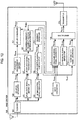
- FIG. 1 A block diagram of a base station in the present embodiment is shown in FIG. 1 , and that of a mobile station in FIG. 2 .
- a receiver 101 in the base station 100 receives a signal from a mobile station 200, establishes uplink synchronization using a guard interval, and outputs a base station receive signal S RXB .
- An uplink RS (Reference Signal) separator 102 separates from the base station receive signal S RXB an uplink RS signal S URSB in which uplink RS signals of a plurality of mobile stations are multiplexed, and outputs it.
- An uplink CQI measurement section 103 receives the uplink RS signals S URSB for a plurality of mobile stations as input, calculates CQI (Channel Quality Indicator) for each mobile station on an RB-by-RB basis, and outputs it as uplink CQI information S UCQB .
- CQI Channel Quality Indicator
- An uplink scheduler 104 makes uplink scheduling for each mobile station.
- the uplink scheduler 104 determines a number of frequency blocks for resources to be allocated based on the uplink CQI information S UCQB . In particular, for good CQI, a larger number of frequency blocks is determined, and for poor CQI, a smaller number of frequency blocks is determined.
- RBs are allocated with an allocation resolution determined in accordance with the determined number of frequency blocks and with the determined number of frequency blocks. Once the allocation resolution has been determined, a structure in the Tree-Based method representing positions of the allocated RBs is determined accordingly.
- the resource allocation information for each frequency block representing the positions of the allocated RBs in a Tree-Based form is combined with the value of the allocation resolution into one piece of scheduling information, that is, one piece of UL Scheduling Grant S USCB , which is output in a number of bits in accordance with the determined structure in the Tree-Based method.
- the number of frequency blocks is also output as S UDFB .
- the uplink scheduler 104 modifies and sets a minimal frequency bandwidth in resource allocation, that is, an allocation resolution, which is a minimal unit for resource block allocation, according to the number of frequency blocks determined based on the uplink CQI information S UCQB . Specifically, a higher allocation resolution is set for a larger number of frequency blocks.
- Resource allocation at the uplink scheduler 104 is made using a correspondence table representing a relationship between the number of frequency blocks and allocation resolution, as shown in FIG. 3 .
- the correspondence table is defined depending upon a communication environment, etc. For example, a higher allocation resolution is defined for a larger number of frequency blocks. By using this relationship, it is possible to hold the number of signaling bits down to 14 bits including notification of the value of the allocation resolution (2 bits) for a number of frequency blocks of four or lower.
- FIGS. 5, 6 , 7 and 8 show examples of RB allocation and UL Scheduling Grant using the Tree-Based method for UE1, UE2, UE3 and UE4, respectively.
- the allocation resolution is 1 RB with reference to the correspondence table in FIG. 3 . Therefore, when allocating resource blocks to UE3 and UE4, they are allocated such that one resource block is allocated with a number of frequency blocks within one.
- 10 RBs, in the Tree-Based method with an allocation resolution of 1 RB a value of any one of 1 - 55 is required (6 bits).
- values of 1 - 55 representing resources of one frequency block are arranged in a tree structure.
- the tree structure in the Tree-Based method varies with the allocation resolution. In other words, the number of bits for UL Scheduling Grant also varies.
- the tree structure when the allocation resolution is 1 RB, the tree structure is constructed from a number sequence of 1 - 55 that can be expressed by 6 bits.
- the allocation resolution is 2 RBs, allocation is made for each unit of two resource blocks, so that it can be handled with a number sequence similar to that for a system band of five RBs. Accordingly, the tree structure is constructed from a number sequence of 1 - 15.
- Scheduling information on resource allocation (UL Scheduling Grant) to be notified to UE3 has 8 bits, and a value of the allocation resolution of "1" and a position of "2" ("2" in FIG. 7 ), which is the position of an allocated resource block represented in a tree structure, are notified thereto.
- UL Scheduling Grant for UE4 has 8 bits, and a value of the allocation resolution of "1" and a position represented in a tree structure, "7" ("7" in FIG. 8 ), are notified thereto.
- the number of frequency blocks is two, and therefore, the allocation resolution is 1 RB with reference to the correspondence table in FIG. 3 .
- the allocation resolution is 1 RB with reference to the correspondence table in FIG. 3 .
- UL Scheduling Grant for UE2 has 14 bits, and a value of the allocation resolution of "1" and positions of allocated resource blocks represented in a tree structure, "3" and “6" ("3" and "6” in FIG. 6 ), are notified thereto.
- the number of frequency blocks is three, and therefore, the allocation resolution is 2 RBs with reference to the correspondence table in FIG 3 .
- the allocation resolution is 2 RBs with reference to the correspondence table in FIG 3 .
- UL Scheduling Grant for UE1 has 14 bits, and a value of the allocation resolution of "2" and positions of allocated resource blocks represented in a tree structure, "0", “2” and “4" ("0", “2” and “4" in FIG. 5 ) are notified thereto.
- the amount of information on resource allocation can be held down within 14 bits even for an increased number of frequency blocks.
- Resource allocation information is composed of n resource indicator values (RIV's).
- the resource indicator value RIV n for an n-th frequency block represents a frequency block at start (RBG start,n ) and a length of subsequent frequency blocks (L CRBGs,n ).
- the n-th resource indicator value RIV n is defined by EQ.
- N UL RBG is the number of frequency blocks in the whole system.
- the number of resource blocks in the whole system is N UL RBG x P (allocation resolution).
- the thus-generated UL Scheduling Grant S USCB is input to a downlink control signal generator 111.
- the downlink control signal generator 111 is also supplied as input with DL Scheduling Grant S DSCB , mobile station identification information S UIDB , and frequency block signal S UDFB with which the number of frequency blocks is indicated.
- the downlink control signal generator 111 multiplexes these input signals to generate a downlink control signal as PDCCH (Physical Downlink Control Channel) S DCCB , and outputs it.
- PDCCH Physical Downlink Control Channel
- a downlink RS signal generator 112 generates a downlink RS signal and outputs it as a downlink RS signal S DRSB .
- a downlink data signal generator 113 receives the DL Scheduling Grant S DSCB as input, multiplexes downlink data signals from a plurality of mobile stations in accordance with an RB pattern indicated by the DL Scheduling Grant S DSCB , generates Physical Downlink Shared Channel (PDSCH) S DCCB , and outputs it.
- PDSCH Physical Downlink Shared Channel
- a multiplexer 114 receives the PDCCH S DCCB , RS signal S DRSB and PDSCH S DDCB as input, multiplexes these signals to generate a downlink multiplexed signal S MUXB , and outputs it.
- a transmitter 115 receives the downlink multiplexed signal S MUXB as input, generates a transmit signal S TXB , and outputs it.
- An uplink data signal separator 106 receives the base station receive signal S RXB as input, extracts therefrom Physical Uplink Shared Channel (PUSCH) S UDCB in which uplink data signals from a plurality of mobile stations are multiplexed, and outputs it.
- An uplink data signal demodulator 109 is supplied with the PUSCH S UDCB as input, demodulates the PUSCH S UDCB , and reproduces mobile station transmitted data.
- PUSCH Physical Uplink Shared Channel
- An uplink control signal separator 108 receives the base station receive signal S RXB as input, extracts therefrom Physical Uplink Control Channel (PUCCH) S UCCB in which uplink control signals from a plurality of mobile stations are multiplexed, and outputs it.
- An uplink control signal demodulator 109 demodulates the PUCCH S UCCB , and outputs a downlink CQI measurement signal S DCQB , which is a result of measurement of downlink CQI transmitted by a plurality of mobile stations.
- a downlink scheduler 110 receives the downlink CQI measurement signal S DCQB as input, makes downlink scheduling for a plurality of mobile stations, generates DL Scheduling Grant S DSCB , which represents information on allocated RBs, and outputs it.
- a UE ID generator 116 generates mobile station identification information S UIDB , and outputs it.
- FIG. 2 is a block diagram showing a main configuration of a mobile station in the present embodiment.
- a receiver 201 in a mobile station 200 receives a signal from the base station 100, establishes downlink synchronization using a guard interval, and outputs a mobile station receive signal S RXU .
- a downlink RS (Reference Signal) separator 202 receives the mobile station receive signal S RXU as input, separates therefrom a downlink RS signal S DRSU in which downlink RS signals are multiplexed, and outputs it.
- a downlink CQI measurement section 203 receives the downlink RS signal S DRSU as input, calculates CQI on an RB-by-RB basis, and outputs it as downlink CQI information S DCQB .
- a downlink control signal separator 206 receives the mobile station receive signal S RXU as input, separates therefrom PDCCH S DCCU in which downlink control signals from a plurality of mobile stations are multiplexed, and outputs it.
- a downlink control signal demodulator 207 receives the PDCCH S DCCU as input, demodulates the PDCCH S DCCU to reproduce a downlink control signal, separates therefrom a result of reproduction in which mobile station identification information corresponding to the mobile station itself is multiplexed, and outputs it as a downlink control reproduced signal S DCMU . It should be noted that only one PDCCH is multiplexed for the mobile station itself.
- the downlink control signal demodulator 207 checks a result of demodulation of the PDCCH S DCCU and reproduction of the downlink control signal as to whether it contains an error, in a case that no error is found, generates a signal indicating ACK, or otherwise, a signal indicating NACK as a downlink control signal decision signal S DAKU , and outputs it.
- the downlink control signal decision signal S DAKU is notified from the mobile station 200 to the base station 100, and in a case that the downlink control signal decision signal S DAKU is NACK, the base station 100 retransmits PDCCH corresponding to the mobile station 200.
- a downlink scheduling information extracting section 208 receives the downlink control reproduced signal S DCMU as input, extracts therefrom downlink RB allocation decision information S DSCU corresponding to downlink resource allocation information, and outputs it.
- An uplink scheduling information extracting section 210 extracts, from the downlink control reproduced signal S DCMU , UL Scheduling Grant that represents information on allocated uplink RBs. Next, it discriminates a tree structure in the Tree-Based method from the value of the allocation resolution contained in the UL Scheduling Grant, identifies an RB indicated by the uplink RB allocation information in this tree structure, and outputs it as uplink RB allocation decision information S USCU .
- An uplink control signal generator 211 receives the uplink RB allocation decision information S USCU and downlink CQI information S DCQB as input, generates Physical Uplink Control Channel (PUCCH) S UCCU in which the downlink CQI information S DCQB is multiplexed with a predetermined resource for a control signal indicated by the uplink RB allocation decision information S USCU , and outputs it.
- PUCCH Physical Uplink Control Channel
- An uplink RS signal generator 212 receives the uplink RB allocation decision information S USCU as input, generates an uplink RS transmit signal S URSU using a predetermined resource for RS in the uplink RB allocation decision information S USCU , and outputs it.
- An uplink data signal generator 213 receives the uplink RB allocation decision information S USCU as input, generates Physical Uplink Shared Channel (PUSCH) S UDCU using a predetermined resource for a data signal in the uplink RB allocation decision information S USCU , and outputs it.
- PUSCH Physical Uplink Shared Channel
- a multiplexer 214 receives the PUCCH S UCCU , uplink RS transmit signal S URSU , PUSCH S UDCU and downlink control signal decision signal S DAKU as input, multiplexes these signals to generate a mobile station multiplexed signal S MUXU , and outputs it.
- the transmitter 215 receives the mobile station multiplexed signal S MUXU as input, generates a mobile station transmit signal S TUX , and transmits it to the base station 100.
- a downlink data signal separator 204 receives the downlink RB allocation receive signal S DSCU and mobile station receive signal S RXU as input, separates therefrom PDSCH S DDCU multiplexed with the downlink RB allocated to the mobile station itself based on the downlink RB allocation decision information S DSCU , and outputs it.
- the downlink data signal demodulator 205 receives PDSCH S DDCU as input, demodulates the PDSCH S DDCU , and reproduces transmitted data from the base station to the mobile station itself.
- the receiver 101 in the base station 100 receives a signal from the mobile station 200, establishes uplink synchronization using a guard interval, and outputs a base station receive signal S RXB (Step S1).
- the uplink RS (Reference Signal) separator 102 separates from the output base station receive signal S RXB an uplink RS signal S URSB in which uplink RS signals from a plurality of mobile stations are multiplexed, and outputs it (Step S2).
- the uplink CQI measurement section 103 calculates CQI (Channel Quality Indicator) for each mobile station on an RB-by-RB basis, and outputs it as uplink CQI information S UCQB (Step S3).
- CQI Channel Quality Indicator
- the uplink scheduler 104 determines a number of frequency blocks for resources to be allocated to each mobile station based on the uplink CQI information S UCQB for each mobile station (Step S4).
- An allocation resolution correlated with the determined number of frequency blocks is determined using the correspondence table as shown in FIG. 3 kept in the equipment itself, whereby a structure in the Tree-Based method is determined, and the number of bits for UL Scheduling Grant is set as a number of bits in accordance with the determined structure in the Tree-Based method (Step S5).
- RBs are allocated with resource blocks in a number equal to the determined allocation resolution and with the determined number of frequency blocks (Step S6).
- the uplink scheduler 104 outputs scheduling information representing positions of the allocated RBs in a Tree-Based form and the value of the allocation resolution in a specified number of bits as UL Scheduling Grant S USCB , and outputs the number of frequency blocks as S UDFB (Step S7).
- the downlink control signal generator 111 is supplied as input with the UL Scheduling Grant S USCB , DL Scheduling Grant S DSCB , mobile station identification information S UIDB and frequency block signal S UDFB , multiplexes these input signals to generate a downlink control signal as PDCCH (Physical Downlink Control Channel) S DCCB , and outputs it (Step S8).
- PDCCH Physical Downlink Control Channel
- the downlink RS signal generator 112 generates a downlink RS signal as a downlink RS signal S DRSB , and outputs it; the downlink data signal generator 113 receives the DL Scheduling Grant S DSCB as input, multiplexes downlink data signals from a plurality of mobile stations together in accordance with an RB pattern indicated by the DL Scheduling Grant S DSCB , generates Physical Downlink Shared Channel (PDSCH) S DDCB , and outputs it (Step S9).
- PDSCH Physical Downlink Shared Channel
- the multiplexer 114 receives the PDCCH S DCCB , RS signal S DRSB and PDSCH S DDCB as input, multiplexes these signals to generate a downlink multiplexed signal S MUXB , and outputs it; the transmitter 115 receives the downlink multiplexed signal S MUXB as input, generates a transmit signal S TXB , and outputs it (Step S10).
- the receiver 201 in the mobile station 200 receives a signal from the base station 100, establishes downlink synchronization using a guard interval, and outputs a mobile station receive signal S RXU (Step S11).
- the downlink RS (Reference Signal) separator 202 receives the mobile station receive signal S RXU as input, and separates therefrom a downlink RS signal S DRSU in which the downlink RS signals are multiplexed; the downlink CQI measurement section 203 receives the downlink RS signal S DRSU as input, calculates CQI on an RB-by-RB basis, and outputs it as downlink CQI information S DCQB (Step S12).
- the downlink control signal separator 206 receives the mobile station receive signal S RXU as input, and separates therefrom PDCCH S DCCU in which downlink control signals from a plurality of mobile stations are multiplexed; the downlink control signal demodulator 207 demodulates the PDCCH S DCCU to reproduce a downlink control signal, separates therefrom a result of reproduction in which mobile station identification information corresponding to the mobile station itself is multiplexed, and outputs it as a downlink control reproduced signal S DCMU (Step S13).
- the downlink scheduling information extracting section 208 receives the downlink control reproduced signal S DCMU as input, extracts therefrom downlink RB allocation decision information S DSCU corresponding to downlink resource allocation information, and outputs it (Step S14).
- the uplink scheduling information extracting section 210 extracts, from the downlink control reproduced signal S DCMU , UL Scheduling Grant, which represents information on allocated uplink RBs, and checks the value of the allocation resolution (Step S15).
- Step S16 it discriminates a tree structure in the Tree-Based method from the value of the allocation resolution, identifies RBs indicated by the uplink RB allocation information in this tree structure, and outputs it as uplink RB allocation decision information S USCU (Step S16).
- the uplink control signal generator 211 receives the uplink RB allocation decision information S USCU and downlink CQI information S DCQB as input, generates Physical Uplink Control Channel (PUCCH) S UCCU in which the downlink CQI information S DCQB is multiplexed with a predetermined resource for a control signal indicated by the uplink RB allocation decision information S USCU , and outputs it (Step S17).
- PUCCH Physical Uplink Control Channel
- the uplink RS signal generator 212 receives the uplink RB allocation decision information S USCU as input, generates an uplink RS transmit signal S URSU using a predetermined resource for RS in the uplink RB allocation decision information S USCU , and outputs it (Step S18).
- the uplink data signal generator 213 receives the uplink RB allocation decision information S USCU as input, generates Physical Uplink Shared Channel (PUSCH) S UDCU using a predetermined resource for a data signal in the uplink RB allocation decision information S USCU , and outputs it (Step S19).
- PUSCH Physical Uplink Shared Channel
- the multiplexer 214 receives the PUCCH S UCCU , uplink RS transmit signal S URSU , PUSCH S UDCU and downlink control signal decision signal S DAKU as input, and multiplexes these signals to generate a mobile station multiplexed signal S MUXU ; the transmitter 215 transmits the mobile station transmit signal S MUXU to the base station 100 (Step S20).
- the present embodiment uses information about a communication environment, such as, for example, the cell size, system bandwidth, coverage of a base station, bandwidth of an uplink sounding reference signal, bandwidth used in uplink data transmission, number of levels in multi-level modulation and code rate used in uplink data transmission, transmittable/receivable bandwidth of a mobile station (sometimes referred to as UE capability), and type of uplink transmission data (VoIP, HTTP, FTP etc.), or information affecting the communication environment, such as the billing scheme in which a user signs on, power headroom (which is a difference between the maximum transmit power of a mobile station and an actual transmit power of the mobile station), and target SINR in uplink power control.
- the cell size is determined by information affecting the communication environment, such as the location of a base station, distance between base stations
- the configuration may be one such that the allocation resolution is set in accordance with a condition of mobile station's channel quality, the information on a communication environment described above, or the information that affect a communication environment described above.
- the number of frequency blocks is described as being notified through Physical Downlink Control Channel (PDCCH), it is additionally notified with a control signal in a higher layer mapped over PBCH (Physical Broadcast Channel), PDSCH (Physical Downlink Shared Channel), which is also referred to as Dynamic BCH, or the like.
- PBCH Physical Downlink Control Channel
- PDSCH Physical Downlink Shared Channel
- a number of frequency blocks S UDFB is input to a PBCH generator or PDSCH generator (both not shown) provided in the downlink control signal generator 111 in the base station, and is notified to a mobile station through the PBCH or PDSCH.
- a PBCH generator or PDSCH generator both not shown
- information on the uplink and downlink control signals varies from frame to frame in about 1 msec, there arises a problem that processing in a terminal becomes complicated in a case that the allocation resolution is modified with such a variation.
- additional limitation may be posed to modify the allocation resolution in a cycle of a plurality of frames.
- a mode may be contemplated in which RBs are allocated with resource blocks in a number equal to the determined allocation resolution and within the determined number of frequency blocks.
- the system band has been described as having 10 RBs for simplifying the explanation above; now an effect of reducing the number of bits in an actual LTE system having a system band of 20 MHz will be described.
- a correspondence table of the number of frequency blocks and allocation resolution as shown FIG. 3 is established so as not to exceed 37 bits, which is an upper limit of the scheduling information stipulated for actual LTE downlink.
- FIG. 3 a correspondence table of the number of frequency blocks and allocation resolution as shown FIG. 3 is established so as not to exceed 37 bits, which is an upper limit of the scheduling information stipulated for actual LTE downlink.
- 11 shows a number of bits required to notify RB patterns for frequency blocks in a number equal to the number of frequency blocks using the Tree-Based method, for numbers of frequency blocks of 1 - 4, respectively.
- the correspondence between the number of frequency blocks and allocation resolution can be established in accordance with an environment, and therefore, it is possible to hold the number of signaling bits for scheduling information down to 35 bits, including notification of an allocation resolution (two bits), which is less than the stipulated upper limit, 37 bits.
- the number of frequency blocks for a mobile station with good channel quality is increased, while that for a mobile station with poor channel quality is decreased, and an allocation resolution is determined accordingly.
- a mobile station with good channel quality performs transmission with a lower electric power density, and hence, with a broader band, and since the channel quality is good as a whole, it will not be degraded even when the allocation resolution is increased with the number of frequency blocks.
- a mobile station with poor channel quality performs transmission with a higher electric power density, and hence, with a narrower band, and since the channel quality is poor as a whole, the allocation resolution must be reduced with the number of frequency blocks in order to accurately select better resources among all.
- the allocation resolution by correlating the allocation resolution, the number of frequency blocks and the channel quality of a mobile station, degradation of the reception property due to setting of an allocation resolution may be reduced.
- the embodiment described above addresses a case in which a base station notifies a value of the allocation resolution borne on UL Scheduling Grant to a mobile station.
- the following embodiment will address a case in which a base station sets an allocation resolution correlated with a number of frequency blocks in one-to-one correspondence, and a mobile station recognizes the allocation resolution from the notified number of frequency blocks. It should be noted that components similar to those in the foregoing embodiment are designated by similar reference numerals and detailed description thereof will be omitted.
- the uplink scheduler 104 in the base station 100 makes uplink scheduling for each mobile station.
- the uplink scheduler 104 determines a number of frequency blocks for resources to be allocated based on uplink CQI information S UCQB .
- RBs are allocated with an allocation resolution set in accordance with the determined number of frequency blocks and with the determined number of frequency blocks.
- the scheduling information representing positions of the allocated RBs is output as UL Scheduling Grant S USCB , and the number of frequency blocks is output as S UDFB .
- the downlink control signal generator 111 in the base station 100 receives the UL Scheduling Grant S USCB , DL Scheduling Grant S DSCB , mobile station identification information S UIDB , and frequency block signal S UDFB as input, multiplexes these signals to generate a downlink control signal as PDCCH (Physical Downlink Control Channel) S DCCB , and outputs it.
- PDCCH Physical Downlink Control Channel
- the number of frequency blocks is notified not only through the Physical Downlink Control Channel (PDCCH) but also through PBCH, PDSCH, etc.
- the downlink control signal demodulator 207 in the mobile station 200 receives the PDCCH S DCCU as input, demodulates the PDCCH S DCCU to reproduce a downlink control signal, separates therefrom a result of reproduction in which mobile station identification information corresponding to the mobile station itself is multiplexed, and outputs it as a downlink control reproduced signal S DCMU .
- the uplink scheduling information extracting section 210 in the mobile station 200 extracts, from the downlink control reproduced signal S DCMU , UL Scheduling Grant, which represents information on allocated uplink RBs, and frequency block signal S UDFU . Next, it recognizes an allocation resolution correlated with the number of frequency blocks in a one-to-one correspondence from the frequency block signal S UDFU and the correspondence table kept by the mobile station itself. It then discriminates a tree structure in the Tree-Based method from the allocation resolution, identifies RBs indicated by the uplink RB allocation information in this tree structure, and outputs it as uplink RB allocation decision information S USCU .
- the receiver 101 in the base station 100 receives a signal from the mobile station 200, establishes uplink synchronization using a guard interval, and outputs a base station receive signal S RXB (Step S1).
- the uplink RS (Reference Signal) separator 102 separates from the output base station receive signal S RXB an uplink RS signal S URSB in which uplink RS signals from a plurality of mobile stations are multiplexed, and outputs it (Step S2).
- the uplink CQI measurement section 103 calculates CQI (Channel Quality Indicator) for each mobile station on an RB-by-RB basis, and outputs it as uplink CQI information S UCQB (Step S3).
- CQI Channel Quality Indicator
- the uplink scheduler 104 determines a number of frequency blocks for resources to be allocated to each mobile station based on the uplink CQI information S UCQB for each mobile station (Step S4).
- An allocation resolution correlated with the determined number of frequency blocks is determined using the correspondence table as shown in FIG. 3 kept in the equipment itself, whereby a structure in the Tree-Based method is determined, and the number of bits for UL Scheduling Grant is set as a number of bits in accordance with the determined structure in the Tree-Based method (Step S5).
- RBs are allocated with resource blocks in a number equal to the determined allocation resolution and with the determined number of frequency blocks (Step S6).
- the uplink scheduler 104 outputs scheduling information representing positions of the allocated RBs in a Tree-Based form in a specified number of bits as UL Scheduling Grant S USCB , and outputs the number of frequency blocks as S UDFB (Step S7-1).
- the downlink control signal generator 111 is supplied as input with the UL Scheduling Grant S USCB , DL Scheduling Grant S DSCB , mobile station identification information S UIDB and frequency block signal S UDFB , multiplexes these input signals to generate a downlink control signal as PDCCH (Physical Downlink Control Channel) S DCCB , and outputs it (Step S8).
- PDCCH Physical Downlink Control Channel
- the downlink RS signal generator 112 generates a downlink RS signal as a downlink RS signal S DRSB , and outputs it; the downlink data signal generator 113 receives the DL Scheduling Grant S DSCB as input, multiplexes downlink data signals from a plurality of mobile stations together in accordance with an RB pattern indicated by the DL Scheduling Grant S DSCB , generates Physical Downlink Shared Channel (PDSCH) S DDCB , and outputs it (Step S9).
- PDSCH Physical Downlink Shared Channel
- the multiplexer 114 receives the PDCCH S DCCB , RS signal S DRSB and PDSCH S DDCB as input, multiplexes these signals to generate a downlink multiplexed signal S MUXB , and outputs it; the downlink multiplexed signal S MUXB is transmitted by the transmitter 115 (Step S10).
- the receiver 201 in the mobile station 200 receives a signal from the base station 100, establishes downlink synchronization using a guard interval, and outputs a mobile station receive signal S RXU (Step S11).
- the downlink RS (Reference Signal) separator 202 receives the mobile station receive signal S RXU as input, and separates therefrom a downlink RS signal S DRSU in which the downlink RS signals are multiplexed; the downlink CQI measurement section 203 calculates CQI from the downlink RS signal S DRSU on an RB-by-RB basis, and outputs it as downlink CQI information S DCQB (Step S12).
- the downlink control signal separator 206 receives the mobile station receive signal S RXU as input, separates therefrom PDCCH S DCCU in which downlink control signals from a plurality of mobile stations are multiplexed, and outputs it; the downlink control signal demodulator 207 demodulates the PDCCH S DCCU to reproduce a downlink control signal, separates therefrom a result of reproduction in which mobile station identification information corresponding to the mobile station itself is multiplexed, and outputs it as a downlink control reproduced signal S DCMU (Step S13).
- the downlink scheduling information extracting section 208 receives the downlink control reproduced signal S DCMU as input, extracts therefrom downlink RB allocation decision information S DSCU corresponding to downlink resource allocation information, and outputs it (Step S14).
- the uplink scheduling information extracting section 210 extracts, from the downlink control reproduced signal S DCMU , UL Scheduling Grant, which represents information on allocated uplink RBs, and frequency block signal S UDFU , and recognizes the value of the allocation resolution based on the number of frequency blocks represented by the frequency block signal S UDFU (Step S15-1).
- Step S16 it discriminates a tree structure in the Tree-Based method from the value of the allocation resolution, identifies RBs indicated by the uplink RB allocation information in this tree structure, and outputs it as uplink RB allocation decision information S USCU (Step S16).
- the uplink control signal generator 211 receives the uplink RB allocation decision information S USCU and downlink CQI information S DCQB as input, generates Physical Uplink Control Channel (PUCCH) S UCCU in which the downlink CQI information S DCQB is multiplexed with a predetermined resource for a control signal indicated by the uplink RB allocation decision information S USCU , and outputs it (Step S17).
- PUCCH Physical Uplink Control Channel
- the uplink RS signal generator 212 receives the uplink RB allocation decision information S USCU as input, generates an uplink RS transmit signal S URSU using a predetermined resource for RS in the uplink RB allocation decision information S USCU , and outputs it (Step S18).
- the uplink data signal generator 213 receives the uplink RB allocation decision information S USCU as input, generates Physical Uplink Shared Channel (PUSCH) S UDCU using a predetermined resource for a data signal in the uplink RB allocation decision information S USCU , and outputs it (Step S19).
- PUSCH Physical Uplink Shared Channel
- the multiplexer 214 receives the PUCCH S UCCU , uplink RS transmit signal S URSU , PUSCH S UDCU and downlink control signal decision signal S DAKU as input, and multiplexes these signals to generate a mobile station multiplexed signal S MUXU ; the transmitter 215 transmits the mobile station transmit signal S MUXU to the base station 100 (Step S20).
- Other methods include one involving correlating the allocation resolution with downlink CQI information and/or with localization information for a mobile station in the uplink control signal that the mobile station notifies to the base station, with MCS (Modulation and Coding Scheme) and/or with power control target value in the downlink control signal that the base station notifies to the mobile station, or the like in a one-to-one correspondence.
- MCS Modulation and Coding Scheme
- the allocation resolution can be shared between the base station and mobile station.
- a tree structure in the Tree-Based method may be discriminated from the number of frequency blocks notified by the base station.
- the number of signaling bits can be reduced by those for notifying the value of the allocation resolution (two bits).
- the embodiments described above have addressed a case in which an allocation resolution is determined in accordance with the number of frequency blocks determined by the uplink scheduler 104.
- the following embodiment will address a case in which an allocation resolution is determined in accordance with a maximum number of frequency blocks determined by a maximum-number-of-frequency-blocks determining section 105 in accordance with uplink CQI. It should be noted that components similar to those in the foregoing embodiments are designated by similar reference numerals and detailed description thereof will be omitted.
- FIG. 13 shows a block diagram of a base station 100 in the present embodiment. This is different from the foregoing embodiments in that a maximum-number-of-frequency-blocks determining section 105 is incorporated.
- the maximum-number-of-frequency-blocks determining section 105 receives uplink CQI information S UCQB as input, determines a maximum number of frequency blocks in resource blocks to be allocated to mobile stations, generates a maximum-frequency-block signal S UDFB for each mobile station, and outputs it.
- a maximum allowable number of frequency blocks may be sometimes set for each base station (cell), for each mobile station, or for each mobile station group.
- the maximum-number-of-frequency-blocks determining section 105 sets a larger maximum number of frequency blocks in a situation that a greater multi-user diversity effect is desirable (in a situation that the system band is broad, or CQI is good), or sets a smaller maximum number of frequency blocks in a situation that an increase in overhead is desired to be held down (in a situation that the system band is narrow, or CQI is poor).
- the uplink scheduler 104 makes uplink scheduling for each mobile station.
- the uplink scheduler 104 receives uplink CQI information S UCQB and maximum-frequency-block signal S UDFB as input, limits the maximum number of frequency blocks for resource blocks to be allocated within a number represented by the maximum-frequency-block signal S UDFB , and makes RB allocation with an allocation resolution corresponding to the maximum-frequency-block signal S UDFB . Then, it outputs scheduling information, which is scheduling information representing the positions of the allocated RBs, and maximum number of frequency blocks as UL Scheduling Grant S USCB .
- FIG. 14 shows a block diagram of a mobile station 200 in the present embodiment. This is different from the foregoing embodiments in that a maximum-number-of-frequency-blocks extracting section 209 is incorporated.
- the maximum-number-of-frequency-blocks extracting section 209 receives downlink control reproduced signal S DCMU as input, separates therefrom a received maximum-frequency-block signal S UDFU for the mobile station itself, and outputs it.
- the uplink scheduling information extracting section 210 extracts, from the downlink control reproduced signal S DCMU , UL Scheduling Grant that represents information on allocated uplink RBs. Next, it discriminates an allocation resolution correlated with the received maximum-frequency-block signal S UDFU in a one-to-one correspondence from the received maximum-frequency-block signal S UDFU output from the maximum-number-of-frequency-blocks extracting section 209. It discriminates a tree structure in the Tree-Based method from the allocation resolution, identifies RBs indicated by the uplink RB allocation information in this tree structure, and outputs it as uplink RB allocation decision information S USCU .
- the receiver 101 in the base station 100 receives a signal from the mobile station 200, establishes uplink synchronization using a guard interval, and outputs a base station receive signal S RXB (Step S1).
- the uplink RS (Reference Signal) separator 102 separates from the output base station receive signal S RXB an uplink RS signal S URSB in which uplink RS signals from a plurality of mobile stations are multiplexed, and outputs it (Step S2).
- the uplink CQI measurement section 103 calculates CQI (Channel Quality Indicator) for each mobile station on an RB-by-RB basis, and outputs it as uplink CQI information S UCQB (Step S3).
- CQI Channel Quality Indicator
- the maximum-number-of-frequency-blocks determining section 105 determines a maximum number of frequency blocks in resource blocks to be allocated to each mobile station based on the uplink CQI information S UCQB , generates a maximum-frequency-block signal S UDFB for each mobile station, and outputs it (Step S4-1).
- the uplink scheduler 104 determines an allocation resolution correlated with the maximum number of frequency blocks represented in the maximum-frequency-block signal S UDFB using the correspondence table as shown in FIG. 3 kept in the equipment itself, whereby it also determines a structure in the Tree-Based method, and sets the number of bits for UL Scheduling Grant as a number of bits in accordance with the determined structure in the Tree-Based method (Step S5).
- RBs are allocated with resource blocks in a number equal to the determined allocation resolution and within the determined number of frequency blocks (Step S6).
- the uplink scheduler 104 outputs scheduling information representing positions of the allocated RBs, and the maximum number of frequency blocks in a specified number of bits as UL Scheduling Grant S USCB (Step S7-2).
- the downlink control signal generator 111 is supplied as input with the UL Scheduling Grant S USCB , DL Scheduling Grant S DSCB , mobile station identification information S UIDB and received maximum-frequency-block signal S UDFB , multiplexes these input signals to generate a downlink control signal as PDCCH (Physical Downlink Control Channel) S DCCB , and outputs it (Step S8).
- PDCCH Physical Downlink Control Channel
- the downlink RS signal generator 112 generates a downlink RS signal as a downlink RS signal S DRSB , and outputs it; the downlink data signal generator 113 receives the DL Scheduling Grant S DSCB as input, multiplexes downlink data signals from a plurality of mobile stations together in accordance with an RB pattern indicated by the DL Scheduling Grant S DSCB , generates Physical Downlink Shared Channel (PDSCH) S DDCB , and outputs it (Step S9).
- PDSCH Physical Downlink Shared Channel
- the multiplexer 114 receives the PDCCH S DCCB , RS signal S DRSB and PDSCH S DDCB as input, and multiplexes these signals to generate a downlink multiplexed signal S MUXB ; the transmitter 115 generates a transmit signal S TXB from the downlink multiplexed signal S MUXB , and outputs it (Step S10).
- the receiver 201 in the mobile station 200 receives a signal from the base station 100, establishes downlink synchronization using a guard interval, and outputs a mobile station receive signal S RXU (Step S11).
- the downlink RS (Reference Signal) separator 202 receives the mobile station receive signal S RXU as input, and separates therefrom a downlink RS signal S DRSU in which the downlink RS signals are multiplexed; the downlink CQI measurement section 203 receives the downlink RS signal S DRSU as input, calculates CQI on an RB-by-RB basis, and outputs it as downlink CQI information S DCQB (Step S12).
- the downlink control signal separator 206 receives the mobile station receive signal S RXU as input, and separates therefrom PDCCH S DCCU in which downlink control signals from a plurality of mobile stations are multiplexed; the downlink control signal demodulator 207 demodulates the PDCCH S DCCU to reproduce a downlink control signal, separates therefrom a result of reproduction in which mobile station identification information corresponding to the mobile station itself is multiplexed, and outputs it as a downlink control reproduced signal S DCMU (Step S13).
- the downlink scheduling information extracting section 208 receives the downlink control reproduced signal S DCMU as input, extracts therefrom downlink RB allocation decision information S DSCU corresponding to downlink resource allocation information, and outputs it (Step S14).
- the maximum-number-of-frequency-blocks extracting section 209 receives the downlink control reproduced signal S DCMU as input, separates therefrom the received maximum-frequency-block signal S UDFU for the mobile station itself, and outputs it; the uplink scheduling information extracting section 210 checks a value of the allocation resolution from the received maximum-frequency-block signal S UDFU (Step S15-2).
- Step S16 it discriminates a tree structure in the Tree-Based method from the value of the allocation resolution, identifies RBs indicated by the uplink RB allocation information in this tree structure, and outputs it as uplink RB allocation decision information S USCU (Step S16).
- the uplink control signal generator 211 receives the uplink RB allocation decision information S USCU and downlink CQI information S DCQB as input, generates Physical Uplink Control Channel (PUCCH) S UCCU in which the downlink CQI information S DCQB is multiplexed with a predetermined resource for a control signal indicated by the uplink RB allocation decision information S USCU , and outputs it (Step S17).
- PUCCH Physical Uplink Control Channel
- the uplink RS signal generator 212 receives the uplink RB allocation decision information S USCU as input, generates an uplink RS transmit signal S URSU using a predetermined resource for RS in the uplink RB allocation decision information S USCU , and outputs it (Step S18).
- the uplink data signal generator 213 receives the uplink RB allocation decision information S USCU as input, generates Physical Uplink Shared Channel (PUSCH) S UDCU using a predetermined resource for a data signal in the uplink RB allocation decision information S USCU , and outputs it (Step S19).
- PUSCH Physical Uplink Shared Channel
- the multiplexer 214 receives the PUCCH S UCCU , uplink RS transmit signal S URSU , PUSCH S UDCU and downlink control signal decision signal S DAKU as input, and multiplexes these signals to generate a mobile station multiplexed signal S MUXU ; the transmitter 215 transmits the mobile station transmit signal S MUXU to the base station 100 (Step S20).
- the maximum number of frequency blocks is notified by a signal mapped to Physical Downlink Shared Channel (PDSCH), which is generally referred to as Physical Broadcast Channel (PBCH) or Dynamic Broadcast Channel (DBCH), in a case that the maximum number of frequency blocks is determined as a cell-specific value. Moreover, for a UE-specific case, it is notified by information on Higher layer signaling mapped to PDSCH. In such a case, there is no need to incorporate the maximum number of frequency blocks into UL Scheduling Grant.
- PDSCH Physical Downlink Shared Channel
- PBCH Physical Broadcast Channel
- DBCH Dynamic Broadcast Channel
- the uplink scheduling information extracting section 210 is configured to extract UL Scheduling Grant from the downlink control reproduced signal S DCMU to discriminate the allocation resolution.
- the maximum-number-of-frequency-blocks determining section determines the maximum number of frequency blocks according to the location of the mobile station and base station.
- FIG. 16 shows a block diagram of a base station 100 for determining the maximum number of frequency blocks according to the location of the mobile station and base station.
- the uplink control signal demodulator 109 demodulates PUCCH S UCCB , and outputs a downlink CQI measurement signal S UCQB , which is a result of measurement of downlink CQI transmitted by a plurality of mobile stations, and received mobile station localization information S ULCB representing the location of the mobile station.
- a maximum-number-of-frequency-blocks determining section 105-1 receives the received mobile station localization information S ULCB as input, determines a maximum number of frequency blocks in frequency resources to be allocated to each mobile station from the location of the mobile station represented by the received mobile station localization information S ULCB , generates a maximum-frequency-block signal S UDFB for each mobile station, and outputs it.
- the maximum number of frequency blocks is determined and generated to have a smaller value for a user located farther away from the base station.
- FIG. 17 shows a block diagram of a mobile station 200 when a maximum number of frequency blocks is determined in accordance with the location of the mobile station and base station.
- a localizing section 416 has a function of locating the mobile station using a signal from a GPS signal satellite, and it receives a signal from the GPS satellite, locates the mobile station 200, generates mobile station localization information S ULCU , and outputs it.
- An uplink control signal generator 211-1 receives the uplink RB allocation decision information S USCU , downlink CQI information S DCQB , and mobile station localization information S ULCU as input, generates PUCCH S UCCU using a predetermined resource for a control signal in resources indicated by the uplink RB allocation decision information S USCU along with the downlink CQI information S DCQB and mobile station localization information S ULCU , and outputs it.
- RBs are allocated with a lower allocation resolution to a mobile station having a smaller maximum number of frequency blocks, and with a higher allocation resolution to a mobile station having a larger maximum number of frequency blocks.
- the maximum-number-of-frequency-blocks determining section determines a maximum number of frequency blocks in accordance with the power headroom, which represents an increasable transmit power in a mobile station.
- FIG. 18 shows a block diagram of a base station 100 in which the maximum number of frequency blocks is determined in accordance with the power headroom, which represents an increasable transmit power in a mobile station.
- an uplink transmit power determining section 517 receives the uplink CQI information S UCQB as input, calculates a transmit power value for the mobile station required to satisfy a required receive power, generates uplink transmit power setting information S UPWB . and outputs it.
- the uplink control signal demodulator 109 demodulates the uplink control signal S UCCB , and outputs a downlink CQI measurement signal S DCQB , which is a result of measurement of downlink CQI transmitted by a plurality of mobile stations, and mobile station power headroom received information S UHRB .
- a maximum-number-of-frequency-blocks determining section 105-2 receives the power headroom received information S UHRB as input, determines a maximum number of frequency blocks in frequency resources to be allocated to each mobile station based on the power headroom received information S UHRB , generates a maximum-frequency-block signal S UDFB for the mobile station, and outputs it.
- P DFUP is a positive real number
- the value represented by the power headroom received information S UHRB is zero and the maximum number of frequency blocks is two or more, the value of the maximum number of frequency blocks is decremented by one. That is, in a case that the transmit power has an extra capacity, the maximum number of frequency blocks is increased to increase the number of allocatable frequency blocks, and enhance the gain in frequency domain channel dependent scheduling. In a case that the transmit power has no extra capacity and is power-limited, the maximum number of frequency blocks is reduced to transmit signals with higher electric power density.
- the downlink control signal generator 511 receives the mobile station identification information S UIDB , UL Scheduling Grant S USCB , DL Scheduling Grant S DSCB , maximum-frequency-block signal S UDFB and uplink transmit power setting information S UPWB as input, generates a downlink control signal in which these signals are multiplexed as PDCCH S DCCB , and outputs it.
- FIG. 19 shows a block diagram of a mobile station 200 in which the maximum number of frequency blocks is determined in accordance with the power headroom, which represents an increasable transmit power in the mobile station.
- an uplink transmit power information extracting section 616 extracts, from the downlink control reproduced signal S DCMU , received uplink transmit power setting value information S UPWU that represents the uplink transmit power value in the mobile station and is notified by the base station, and outputs it.
- a power headroom calculating section 617 receives the received uplink transmit power setting value information S UPWU as input, subtracts the received uplink transmit power setting value information S UPWU from the maximum transmit power value transmittable by the mobile station, and outputs the resulting value as mobile station power headroom information S UHRU .
- the mobile station power headroom information S UHRU represents the remaining electric power with which the mobile station can perform additional transmission after transmission with an electric power represented by the received uplink transmit power setting value information S UPWU .
- An uplink control signal generator 211-2 receives the uplink RB allocation decision information S USCU , downlink CQI information S DCQB , and mobile station power headroom information S UHRU as input, generates PUCCH S UCCU using a predetermined resource for a control signal in resources represented by the uplink RB allocation decision information S USCU along with the downlink CQI information S DCQB and mobile station power headroom information S UHRU , and outputs it.
- RBs are allocated with a lower allocation resolution to a mobile station having a smaller maximum number of frequency blocks, and with a higher allocation resolution to a mobile station having a larger maximum number of frequency blocks.
- RBs are allocated with a lower allocation resolution to a mobile station having a smaller maximum number of frequency blocks, and with a higher allocation resolution to a mobile station having a larger maximum number of frequency blocks, so that an increase in the amount of signaling due to an increase of the number of frequency blocks can be prevented.
- the first and second embodiments have addressed a case in which an allocation resolution is determined in accordance with the number of frequency blocks determined by the scheduler
- the third embodiment has addressed a case in which an allocation resolution is determined in accordance with the maximum number of frequency blocks determined by the maximum-number-of-frequency-blocks determining section.
- the following embodiment is characterized in checking a sequence of resource blocks allocated in accordance with any one of the embodiments described above, and in a case that transmission may be made with a number of bits smaller than that for determining information representing the allocated resource blocks, performing transmission with a smaller number of bits. It should be noted that components similar to those in the foregoing embodiment are designated by similar reference numerals and detailed description thereof will be omitted.
- the allocation resolution is set as one with reference to the correspondence table in FIG. 3 .
- resource blocks at positions numbered "2,” “3,” “4" and "5" are allocated as shown in FIG. 20 .
- a value "32" within 1 - 55 (six bits) is used to make denotation in the Tree-Based method.
- FIG 21 it may be denoted in the Tree-Based method using a value "6" within 1 - 15 that can be denoted by four bits.
- resource block allocation may be denoted in the Tree-Based method with a smaller number of bits.
- the uplink scheduler 104 in the present embodiment checks a sequence of allocated resource blocks, and in a case that transmission may be made with a number of bits smaller than that for determining information representing the allocated resource blocks, updates the value of the allocation resolution determined once and outputs UL Scheduling Grant in a number of bits in accordance with the updated value of the allocation resolution.
- the receiver 101 in the base station 100 receives a signal from the mobile station 200, establishes uplink synchronization using a guard interval, and outputs a base station receive signal S RXB (Step S1).
- the uplink RS (Reference Signal) separator 102 separates from the output base station receive signal S RXB an uplink RS signal S URSB in which uplink RS signals from a plurality of mobile stations are multiplexed, and outputs it (Step S2).
- the uplink CQI measurement section 103 calculates CQI (Channel Quality Indicator) for each mobile station on an RB-by-RB basis, and outputs it as uplink CQI information S UCQB (Step S3).
- CQI Channel Quality Indicator
- the uplink scheduler 104 determines a number of frequency blocks for resources to be allocated to each mobile station based on the uplink CQI information S UCQB for each mobile station (Step S4). An allocation resolution correlated with the determined number of frequency blocks is determined using the correspondence table as shown in FIG. 3 kept in the equipment itself (Step S5).
- RBs are allocated with resource blocks in a number equal to the determined allocation resolution and with the determined number of frequency blocks (Step S6).
- Step S21 decision is made as to whether transmission may be made with a number of bits smaller than that for determining information representing the allocated resource blocks.
- the value of the allocation resolution determined once is updated, and the number of bits is set to that in accordance with the allocation resolution from the updated number of bits for UL Scheduling Grant (Step S22).
- the flow goes to Step S7-1.
- the uplink scheduler 104 outputs scheduling information representing positions of the allocated RBs and value of the allocation resolution in a specified number of bits as UL Scheduling Grant S USCB , and outputs the number of frequency blocks as S UDFB (Step S7-1).
- the downlink control signal generator 111 is supplied as input with the UL Scheduling Grant S USCB , DL Scheduling Grant S DSCB , mobile station identification information S UIDB and frequency block signal S UDFB , multiplexes these input signals to generate a downlink control signal as PDCCH (Physical Downlink Control Channel) S DCCB , and outputs it (Step S8).
- PDCCH Physical Downlink Control Channel
- the downlink RS signal generator 112 generates a downlink RS signal as a downlink RS signal S DRSB ; the downlink data signal generator 113 multiplexes downlink data signals from a plurality of mobile stations together in accordance with an RB pattern indicated by the DL Scheduling Grant S DSCB , generates Physical Downlink Shared Channel (PDSCH) S DDCB , and outputs it (Step S9).
- PDSCH Physical Downlink Shared Channel
- the multiplexer 114 receives the PDCCH S DCCB , RS signal S DRSB and PDSCH S DDCB as input, and multiplexes these signals to generate a downlink multiplexed signal S MUXB ; the transmitter 115 generates a transmit signal S TXB from the downlink multiplexed signal S MUXB , and transmits it (Step S10).
- the receiver 201 in the mobile station 200 receives a signal from the base station 100, establishes downlink synchronization using a guard interval, and outputs a mobile station receive signal S RXU (Step S11).
- the downlink RS (Reference Signal) separator 202 receives the mobile station receive signal S RXU as input, separates therefrom a downlink RS signal S DRSU in which the downlink RS signals are multiplexed, and outputs it; the downlink CQI measurement section 203 calculates CQI from the downlink RS signal S DRSU on an RB-by-RB basis, and outputs it as downlink CQI information S DCQB (Step S12).
- the downlink control signal separator 206 receives the mobile station receive signal S RXU as input, and separates therefrom PDCCH S DCCU in which downlink control signals from a plurality of mobile stations are multiplexed; the downlink control signal demodulator 207 demodulates the PDCCH S DCCU to reproduce a downlink control signal, separates therefrom a result of reproduction in which mobile station identification information corresponding to the mobile station itself is multiplexed, and outputs it as a downlink control reproduced signal S DCMU (Step S13).
- the downlink scheduling information extracting section 208 receives the downlink control reproduced signal S DCMU as input, extracts therefrom downlink RB allocation decision information S DSCU corresponding to downlink resource allocation information, and outputs it (Step S14).
- the uplink scheduling information extracting section 210 extracts, from the downlink control reproduced signal S DCMU , UL Scheduling Grant, which represents information on allocated uplink RBs, and checks the value of the allocation resolution (Step S15).
- Step S16 it discriminates a tree structure in the Tree-Based method from the value of the allocation resolution, identifies RBs indicated by the uplink RB allocation information in this tree structure, and outputs it as uplink RB allocation decision information S USCU (Step S16).
- the uplink control signal generator 211 receives the uplink RB allocation decision information S USCU and downlink CQI information S DCQB as input, generates Physical Uplink Control Channel (PUCCH) S UCCU in which the downlink CQI information S DCQB is multiplexed with a predetermined resource for a control signal indicated by the uplink RB allocation decision information S USCU , and outputs it (Step S17).
- PUCCH Physical Uplink Control Channel
- the uplink RS signal generator 212 receives the uplink RB allocation decision information S USCU as input, generates an uplink RS transmit signal S URSU using a predetermined resource for RS in the uplink RB allocation decision information S USCU , and outputs it (Step S18).
- the uplink data signal generator 213 receives the uplink RB allocation decision information S USCU as input, generates Physical Uplink Shared Channel (PUSCH) S UDCU using a predetermined resource for a data signal in the uplink RB allocation decision information S USCU , and outputs it (Step S19).
- PUSCH Physical Uplink Shared Channel
- the multiplexer 214 receives the PUCCH S UCCU , uplink RS transmit signal S URSU , PUSCH S UDCU and downlink control signal decision signal S DAKU as input, and multiplexes these signals to generate a mobile station multiplexed signal S MUXU ; the transmitter 215 transmits the mobile station transmit signal S MUXU to the base station 100 (Step S20).
- UL Scheduling Grant can be reliably transmitted with a smaller number of bits.
- the mode may be one such that downlink resource blocks are allocated.
- the number of frequency blocks or maximum number of frequency blocks may be information varying in accordance with a communication environment, such as, for example, the cell size, system bandwidth, coverage of a base station, channel quality information measured by a downlink reference signal, bandwidth of downlink data signals, and number of levels in multi-level modulation for downlink data signals, or code rate.
- the aforementioned cell size is determined by information affecting the communication environment such as the location of a base station, distance between base stations, and interference power, the number of frequency blocks may be selected using such information.
- a processor operated by programs stored in a program memory implements functions and operations similar to those in the embodiments described above. It should be noted that part of functions of the embodiments described above may be implemented by a computer program.
Priority Applications (2)
| Application Number | Priority Date | Filing Date | Title |
|---|---|---|---|
| EP19183064.5A EP3567790B1 (de) | 2008-06-20 | 2009-06-19 | Ressourcen-zuweisungsverfahren und vorrichtung |
| EP23189266.2A EP4247091A3 (de) | 2008-06-20 | 2009-06-19 | Ressourcen-zuweisungsverfahren und vorrichtung |
Applications Claiming Priority (3)
| Application Number | Priority Date | Filing Date | Title |
|---|---|---|---|
| JP2008161752 | 2008-06-20 | ||
| PCT/JP2009/061194 WO2009154270A1 (ja) | 2008-06-20 | 2009-06-19 | リソース割当方法、特定方法、無線通信システム、基地局、移動局、及びプログラム |
| EP09766718.2A EP2291042B1 (de) | 2008-06-20 | 2009-06-19 | Ressourcenzuweisungsverfahren, basisstation, mobilstation und programm |
Related Parent Applications (2)
| Application Number | Title | Priority Date | Filing Date |
|---|---|---|---|
| EP09766718.2A Division EP2291042B1 (de) | 2008-06-20 | 2009-06-19 | Ressourcenzuweisungsverfahren, basisstation, mobilstation und programm |
| EP09766718.2A Division-Into EP2291042B1 (de) | 2008-06-20 | 2009-06-19 | Ressourcenzuweisungsverfahren, basisstation, mobilstation und programm |
Related Child Applications (3)
| Application Number | Title | Priority Date | Filing Date |
|---|---|---|---|
| EP19183064.5A Division EP3567790B1 (de) | 2008-06-20 | 2009-06-19 | Ressourcen-zuweisungsverfahren und vorrichtung |
| EP19183064.5A Division-Into EP3567790B1 (de) | 2008-06-20 | 2009-06-19 | Ressourcen-zuweisungsverfahren und vorrichtung |
| EP23189266.2A Division EP4247091A3 (de) | 2008-06-20 | 2009-06-19 | Ressourcen-zuweisungsverfahren und vorrichtung |
Publications (2)
| Publication Number | Publication Date |
|---|---|
| EP3358780A1 true EP3358780A1 (de) | 2018-08-08 |
| EP3358780B1 EP3358780B1 (de) | 2021-11-10 |
Family
ID=41434182
Family Applications (4)
| Application Number | Title | Priority Date | Filing Date |
|---|---|---|---|
| EP09766718.2A Active EP2291042B1 (de) | 2008-06-20 | 2009-06-19 | Ressourcenzuweisungsverfahren, basisstation, mobilstation und programm |
| EP23189266.2A Pending EP4247091A3 (de) | 2008-06-20 | 2009-06-19 | Ressourcen-zuweisungsverfahren und vorrichtung |
| EP19183064.5A Active EP3567790B1 (de) | 2008-06-20 | 2009-06-19 | Ressourcen-zuweisungsverfahren und vorrichtung |
| EP18164806.4A Active EP3358780B1 (de) | 2008-06-20 | 2009-06-19 | Ressourcenzuweisungsverfahren, basisstation und mobilstation |
Family Applications Before (3)
| Application Number | Title | Priority Date | Filing Date |
|---|---|---|---|
| EP09766718.2A Active EP2291042B1 (de) | 2008-06-20 | 2009-06-19 | Ressourcenzuweisungsverfahren, basisstation, mobilstation und programm |
| EP23189266.2A Pending EP4247091A3 (de) | 2008-06-20 | 2009-06-19 | Ressourcen-zuweisungsverfahren und vorrichtung |
| EP19183064.5A Active EP3567790B1 (de) | 2008-06-20 | 2009-06-19 | Ressourcen-zuweisungsverfahren und vorrichtung |
Country Status (7)
| Country | Link |
|---|---|
| US (7) | US9350485B2 (de) |
| EP (4) | EP2291042B1 (de) |
| JP (1) | JP5440802B2 (de) |
| KR (1) | KR101228052B1 (de) |
| CN (1) | CN102067694B (de) |
| ES (2) | ES2905580T3 (de) |
| WO (1) | WO2009154270A1 (de) |
Families Citing this family (33)
| Publication number | Priority date | Publication date | Assignee | Title |
|---|---|---|---|---|
| WO2002101941A2 (en) | 2001-06-13 | 2002-12-19 | Tantivy Communications, Inc. | System and method for coordination of wireless maintenance channel power control |
| TWI332326B (en) * | 2002-10-17 | 2010-10-21 | Interdigital Tech Corp | Power control for communications systems utilizing high speed shared channels |
| JP2009231976A (ja) * | 2008-03-19 | 2009-10-08 | Nec Corp | 異なる無線アクセス方式間のハンドオーバ方法および無線通信システム |
| EP3258638B1 (de) | 2008-06-20 | 2019-10-02 | NEC Corporation | Ressourcenzuweisungsverfahren und basisstation |
| ES2905580T3 (es) * | 2008-06-20 | 2022-04-11 | Nec Corp | Método de asignación de recursos, estación base y estación móvil |
| JP5330843B2 (ja) * | 2009-01-28 | 2013-10-30 | 京セラ株式会社 | 無線基地局および通信制御方法 |
| DK2400807T3 (en) * | 2009-02-18 | 2018-10-29 | Sun Patent Trust | SCHEDULING APPARATUS AND IDS PLANNING PROCEDURE |
| US9036518B2 (en) | 2009-03-17 | 2015-05-19 | Nec Corporation | Wireless base station apparatus, wireless communication system, wireless communication method, and program |
| JP5528123B2 (ja) * | 2010-01-05 | 2014-06-25 | シャープ株式会社 | 通信装置、通信装置の制御プログラムおよび集積回路 |
| US8867459B2 (en) * | 2010-03-08 | 2014-10-21 | Broadcom Corporation | Mobile subscriber information transmission over multiple uplink frames |
| US9236975B2 (en) | 2010-03-08 | 2016-01-12 | Broadcom Corporation | Mobile subscriber information transmission over multiple uplink frames |
| WO2011152663A2 (ko) * | 2010-06-01 | 2011-12-08 | 엘지전자 주식회사 | 무선 통신 시스템에서 자원 할당 방법 및 장치 |
| US8488529B2 (en) * | 2011-01-05 | 2013-07-16 | Telefonaktiebolaget Lm Ericsson (Publ) | Efficient information mapping for transmission grants |
| CN102056306B (zh) * | 2011-01-14 | 2013-10-16 | 大唐移动通信设备有限公司 | 上行共享信道资源分配的方法、装置及一种通信系统 |
| WO2012150762A2 (ko) * | 2011-05-02 | 2012-11-08 | 주식회사 팬택 | 자원할당정보의 전송장치 및 방법 |
| WO2012173385A2 (ko) * | 2011-06-13 | 2012-12-20 | 엘지전자 주식회사 | 무선통신 시스템에서 자원 할당 방법 및 장치 |
| CN102891710B (zh) * | 2011-07-20 | 2015-12-02 | 华为技术有限公司 | 一种获取信道状态信息的方法及装置 |
| US20140169316A1 (en) * | 2011-07-27 | 2014-06-19 | Lg Electronics Inc. | Method and apparatus for signal transceiving in wireless communication system |
| KR20140101830A (ko) | 2011-08-12 | 2014-08-20 | 인터디지탈 패튼 홀딩스, 인크 | 무선 시스템에서의 융통성있는 대역폭 동작을 위한 다운링크 리소스 할당 |
| KR101964349B1 (ko) | 2012-03-19 | 2019-04-01 | 한국전자통신연구원 | 통신 시스템에서 자원 할당 장치 및 방법 |
| JP2015019177A (ja) | 2013-07-09 | 2015-01-29 | 京セラ株式会社 | ネットワーク装置及び通信制御方法 |
| CN103500124A (zh) * | 2013-10-22 | 2014-01-08 | 中国农业银行股份有限公司 | 一种向多图形处理器分配数据的方法和系统 |
| CN104363659B (zh) * | 2014-10-24 | 2018-09-21 | 上海华为技术有限公司 | 一种资源分配装置、系统及方法 |
| CN105992354B (zh) * | 2015-01-30 | 2021-05-11 | 中兴通讯股份有限公司 | 一种资源分配的指示方法及装置 |
| CN105636211B (zh) * | 2015-06-30 | 2019-03-22 | 宇龙计算机通信科技(深圳)有限公司 | 资源分配的指示方法及指示装置、基站和终端 |
| US10492181B2 (en) * | 2016-01-20 | 2019-11-26 | Qualcomm Incorporated | Communication of uplink control information |
| US10433283B2 (en) | 2016-01-26 | 2019-10-01 | Huawei Technologies Co., Ltd. | System and method for bandwidth division and resource block allocation |
| WO2017155323A1 (ko) * | 2016-03-10 | 2017-09-14 | 엘지전자 주식회사 | 무선 통신 시스템에서 신호를 송수신하기 위한 방법 및 이를 위한 장치 |
| EP3443792B1 (de) * | 2016-05-13 | 2020-11-04 | Sony Corporation | Kommunikationsvorrichtung, infrastrukturausrüstung, drahtloskommunikationsnetzwerk und -verfahren |
| EP3855812B1 (de) | 2016-08-08 | 2022-10-05 | LG Electronics Inc. | Verfahren und vorrichtung zur meldung von csi |
| WO2018038663A1 (en) | 2016-08-24 | 2018-03-01 | Telefonaktiebolaget Lm Ericsson (Publ) | Methods for efficient signaling in v2x communications |
| WO2018137214A1 (zh) * | 2017-01-25 | 2018-08-02 | 华为技术有限公司 | 一种资源分配方法及第一节点、第二节点 |
| CN110351849B (zh) | 2018-04-04 | 2023-07-04 | 大唐移动通信设备有限公司 | 资源分配方法及装置、基站和终端 |
Family Cites Families (24)
| Publication number | Priority date | Publication date | Assignee | Title |
|---|---|---|---|---|
| US7016319B2 (en) | 2003-03-24 | 2006-03-21 | Motorola, Inc. | Method and apparatus for reducing co-channel interference in a communication system |
| JP4780298B2 (ja) | 2003-12-24 | 2011-09-28 | 日本電気株式会社 | 無線通信システム、無線通信装置及びそれに用いるリソース割当て方法 |
| JP5118026B2 (ja) * | 2005-06-15 | 2013-01-16 | ホアウェイ・テクノロジーズ・カンパニー・リミテッド | 通信リソース割当方法及びシステム |
| US8077690B2 (en) * | 2005-08-24 | 2011-12-13 | Motorola Mobility, Inc. | Resource allocation in cellular communication systems |
| ES2540931T3 (es) * | 2006-01-18 | 2015-07-14 | Telefonaktiebolaget Lm Ericsson (Publ) | Transmisión localizada y distribuida |
| KR101221821B1 (ko) | 2006-04-21 | 2013-01-14 | 삼성전자주식회사 | 주파수 분할 다중 접속 시스템에서 자원 할당 정보 시그널링 방법 |
| CN101064903B (zh) | 2006-04-25 | 2011-12-21 | 华为技术有限公司 | 一种通信系统资源分配指示方法、基站及用户设备 |
| CN101119277A (zh) | 2006-08-03 | 2008-02-06 | 北京三星通信技术研究有限公司 | 传输控制信令的设备和方法 |
| JP5077525B2 (ja) | 2006-08-22 | 2012-11-21 | 日本電気株式会社 | 無線通信システムにおけるリファレンス信号多重方法および無線通信装置 |
| JP4904994B2 (ja) * | 2006-08-25 | 2012-03-28 | 富士通東芝モバイルコミュニケーションズ株式会社 | 移動無線端末装置 |
| JP4940867B2 (ja) | 2006-09-29 | 2012-05-30 | 日本電気株式会社 | 移動通信システムにおける制御信号およびリファレンス信号の多重方法、リソース割当方法および基地局 |
| KR100910707B1 (ko) | 2006-10-19 | 2009-08-04 | 엘지전자 주식회사 | 제어신호 전송 방법 |
| JP5092350B2 (ja) * | 2006-10-26 | 2012-12-05 | 富士通株式会社 | パイロット信号伝送方法及び移動通信システム |
| JP4995280B2 (ja) | 2006-11-01 | 2012-08-08 | サムスン エレクトロニクス カンパニー リミテッド | パケットデータ通信システムにおける制御情報を送受信する方法及び装置 |
| KR101319877B1 (ko) * | 2006-11-01 | 2013-10-18 | 엘지전자 주식회사 | 자원 할당 방법 및 자원 할당 정보 전송 방법 |
| US7924809B2 (en) * | 2006-11-22 | 2011-04-12 | Intel Corporation | Techniques to provide a channel quality indicator |
| US7957759B2 (en) * | 2006-12-08 | 2011-06-07 | Texas Instruments Incorporated | Wideband reference signal transmission in SC-FDMA communication systems |
| JP5147233B2 (ja) | 2006-12-27 | 2013-02-20 | 川崎エンジニアリング株式会社 | ガスの脱硫方法および脱硫設備 |
| US9295003B2 (en) * | 2007-03-19 | 2016-03-22 | Apple Inc. | Resource allocation in a communication system |
| WO2008123037A1 (ja) * | 2007-03-20 | 2008-10-16 | Ntt Docomo, Inc. | 移動通信システムで使用される基地局装置、ユーザ装置及び方法 |
| KR101468490B1 (ko) | 2007-05-02 | 2014-12-10 | 삼성전자주식회사 | 무선 통신 시스템에서 제어 채널들의 집합을 한정하여 송수신하는 방법 및 장치 |
| US7933350B2 (en) | 2007-10-30 | 2011-04-26 | Telefonaktiebolaget Lm Ericsson (Publ) | Channel-dependent frequency-domain scheduling in an orthogonal frequency division multiplexing communications system |
| ES2905580T3 (es) | 2008-06-20 | 2022-04-11 | Nec Corp | Método de asignación de recursos, estación base y estación móvil |
| EP3258638B1 (de) | 2008-06-20 | 2019-10-02 | NEC Corporation | Ressourcenzuweisungsverfahren und basisstation |
-
2009
- 2009-06-19 ES ES18164806T patent/ES2905580T3/es active Active
- 2009-06-19 EP EP09766718.2A patent/EP2291042B1/de active Active
- 2009-06-19 EP EP23189266.2A patent/EP4247091A3/de active Pending
- 2009-06-19 JP JP2010517974A patent/JP5440802B2/ja active Active
- 2009-06-19 ES ES09766718.2T patent/ES2685481T3/es active Active
- 2009-06-19 US US13/000,301 patent/US9350485B2/en active Active
- 2009-06-19 CN CN200980123201.8A patent/CN102067694B/zh active Active
- 2009-06-19 EP EP19183064.5A patent/EP3567790B1/de active Active
- 2009-06-19 EP EP18164806.4A patent/EP3358780B1/de active Active
- 2009-06-19 KR KR1020107028617A patent/KR101228052B1/ko active IP Right Grant
- 2009-06-19 WO PCT/JP2009/061194 patent/WO2009154270A1/ja active Application Filing
-
2016
- 2016-04-19 US US15/132,569 patent/US9668256B2/en active Active
-
2017
- 2017-04-26 US US15/497,335 patent/US10091779B2/en active Active
-
2018
- 2018-08-20 US US16/105,024 patent/US10716106B2/en active Active
-
2020
- 2020-06-17 US US16/903,627 patent/US11395285B2/en active Active
-
2022
- 2022-05-31 US US17/828,098 patent/US20220295460A1/en active Pending
-
2023
- 2023-06-16 US US18/211,126 patent/US20230337248A1/en active Pending
Non-Patent Citations (3)
| Title |
|---|
| "Uplink Resource Allocation for E-UTRA", 3GPP R1-070881, February 2007 (2007-02-01) |
| NEC GROUP: "DL Distributed Resource Signalling for EUTRA", 3GPP DRAFT; R1-072826, 3RD GENERATION PARTNERSHIP PROJECT (3GPP), MOBILE COMPETENCE CENTRE ; 650, ROUTE DES LUCIOLES ; F-06921 SOPHIA-ANTIPOLIS CEDEX ; FRANCE, vol. RAN WG1, no. Orlando, USA; 20070620, 20 June 2007 (2007-06-20), XP050106507 * |
| NEC GROUP: "DL Unicast Resource Allocation Signalling using L1L2 control channels", 3GPP DRAFT; R1-074715, 3RD GENERATION PARTNERSHIP PROJECT (3GPP), MOBILE COMPETENCE CENTRE ; 650, ROUTE DES LUCIOLES ; F-06921 SOPHIA-ANTIPOLIS CEDEX ; FRANCE, vol. RAN WG1, no. Korea; 20071030, 30 October 2007 (2007-10-30), XP050108190 * |
Also Published As
| Publication number | Publication date |
|---|---|
| WO2009154270A1 (ja) | 2009-12-23 |
| US20200314825A1 (en) | 2020-10-01 |
| EP2291042A4 (de) | 2014-08-27 |
| US11395285B2 (en) | 2022-07-19 |
| EP4247091A2 (de) | 2023-09-20 |
| US20220295460A1 (en) | 2022-09-15 |
| US20230337248A1 (en) | 2023-10-19 |
| US20160234817A1 (en) | 2016-08-11 |
| EP4247091A3 (de) | 2023-11-22 |
| ES2685481T3 (es) | 2018-10-09 |
| EP2291042A1 (de) | 2011-03-02 |
| KR20110021908A (ko) | 2011-03-04 |
| US9350485B2 (en) | 2016-05-24 |
| US9668256B2 (en) | 2017-05-30 |
| EP3567790B1 (de) | 2023-09-06 |
| ES2905580T3 (es) | 2022-04-11 |
| JPWO2009154270A1 (ja) | 2011-12-01 |
| JP5440802B2 (ja) | 2014-03-12 |
| US10716106B2 (en) | 2020-07-14 |
| US20110110322A1 (en) | 2011-05-12 |
| US10091779B2 (en) | 2018-10-02 |
| EP2291042B1 (de) | 2018-05-30 |
| CN102067694B (zh) | 2015-04-29 |
| US20170230949A1 (en) | 2017-08-10 |
| CN102067694A (zh) | 2011-05-18 |
| EP3567790A1 (de) | 2019-11-13 |
| US20180359736A1 (en) | 2018-12-13 |
| KR101228052B1 (ko) | 2013-01-31 |
| EP3358780B1 (de) | 2021-11-10 |
Similar Documents
| Publication | Publication Date | Title |
|---|---|---|
| US20230337248A1 (en) | Resource allocation method, identification method, radio communication system, base station, mobile station, and program | |
| US11405901B2 (en) | Resource allocation method, identification method, base station, mobile station, and program |
Legal Events
| Date | Code | Title | Description |
|---|---|---|---|
| PUAI | Public reference made under article 153(3) epc to a published international application that has entered the european phase |
Free format text: ORIGINAL CODE: 0009012 |
|
| STAA | Information on the status of an ep patent application or granted ep patent |
Free format text: STATUS: REQUEST FOR EXAMINATION WAS MADE |
|
| 17P | Request for examination filed |
Effective date: 20180328 |
|
| AC | Divisional application: reference to earlier application |
Ref document number: 2291042 Country of ref document: EP Kind code of ref document: P |
|
| AK | Designated contracting states |
Kind code of ref document: A1 Designated state(s): AT BE BG CH CY CZ DE DK EE ES FI FR GB GR HR HU IE IS IT LI LT LU LV MC MK MT NL NO PL PT RO SE SI SK TR |
|
| RBV | Designated contracting states (corrected) |
Designated state(s): AT BE BG CH CY CZ DE DK EE ES FI FR GB GR HR HU IE IS IT LI LT LU LV MC MK MT NL NO PL PT RO SE SI SK TR |
|
| STAA | Information on the status of an ep patent application or granted ep patent |
Free format text: STATUS: EXAMINATION IS IN PROGRESS |
|
| 17Q | First examination report despatched |
Effective date: 20200107 |
|
| STAA | Information on the status of an ep patent application or granted ep patent |
Free format text: STATUS: EXAMINATION IS IN PROGRESS |
|
| GRAP | Despatch of communication of intention to grant a patent |
Free format text: ORIGINAL CODE: EPIDOSNIGR1 |
|
| STAA | Information on the status of an ep patent application or granted ep patent |
Free format text: STATUS: GRANT OF PATENT IS INTENDED |
|
| INTG | Intention to grant announced |
Effective date: 20210607 |
|
| GRAS | Grant fee paid |
Free format text: ORIGINAL CODE: EPIDOSNIGR3 |
|
| GRAA | (expected) grant |
Free format text: ORIGINAL CODE: 0009210 |
|
| STAA | Information on the status of an ep patent application or granted ep patent |
Free format text: STATUS: THE PATENT HAS BEEN GRANTED |
|
| AC | Divisional application: reference to earlier application |
Ref document number: 2291042 Country of ref document: EP Kind code of ref document: P |
|
| AK | Designated contracting states |
Kind code of ref document: B1 Designated state(s): AT BE BG CH CY CZ DE DK EE ES FI FR GB GR HR HU IE IS IT LI LT LU LV MC MK MT NL NO PL PT RO SE SI SK TR |
|
| REG | Reference to a national code |
Ref country code: GB Ref legal event code: FG4D |
|
| REG | Reference to a national code |
Ref country code: AT Ref legal event code: REF Ref document number: 1447061 Country of ref document: AT Kind code of ref document: T Effective date: 20211115 Ref country code: CH Ref legal event code: EP |
|
| REG | Reference to a national code |
Ref country code: DE Ref legal event code: R096 Ref document number: 602009064157 Country of ref document: DE |
|
| REG | Reference to a national code |
Ref country code: IE Ref legal event code: FG4D |
|
| REG | Reference to a national code |
Ref country code: NL Ref legal event code: FP |
|
| REG | Reference to a national code |
Ref country code: LT Ref legal event code: MG9D |
|
| REG | Reference to a national code |
Ref country code: ES Ref legal event code: FG2A Ref document number: 2905580 Country of ref document: ES Kind code of ref document: T3 Effective date: 20220411 |
|
| REG | Reference to a national code |
Ref country code: AT Ref legal event code: MK05 Ref document number: 1447061 Country of ref document: AT Kind code of ref document: T Effective date: 20211110 |
|
| PG25 | Lapsed in a contracting state [announced via postgrant information from national office to epo] |
Ref country code: LT Free format text: LAPSE BECAUSE OF FAILURE TO SUBMIT A TRANSLATION OF THE DESCRIPTION OR TO PAY THE FEE WITHIN THE PRESCRIBED TIME-LIMIT Effective date: 20211110 Ref country code: FI Free format text: LAPSE BECAUSE OF FAILURE TO SUBMIT A TRANSLATION OF THE DESCRIPTION OR TO PAY THE FEE WITHIN THE PRESCRIBED TIME-LIMIT Effective date: 20211110 Ref country code: BG Free format text: LAPSE BECAUSE OF FAILURE TO SUBMIT A TRANSLATION OF THE DESCRIPTION OR TO PAY THE FEE WITHIN THE PRESCRIBED TIME-LIMIT Effective date: 20220210 Ref country code: AT Free format text: LAPSE BECAUSE OF FAILURE TO SUBMIT A TRANSLATION OF THE DESCRIPTION OR TO PAY THE FEE WITHIN THE PRESCRIBED TIME-LIMIT Effective date: 20211110 |
|
| PG25 | Lapsed in a contracting state [announced via postgrant information from national office to epo] |
Ref country code: IS Free format text: LAPSE BECAUSE OF FAILURE TO SUBMIT A TRANSLATION OF THE DESCRIPTION OR TO PAY THE FEE WITHIN THE PRESCRIBED TIME-LIMIT Effective date: 20220310 Ref country code: SE Free format text: LAPSE BECAUSE OF FAILURE TO SUBMIT A TRANSLATION OF THE DESCRIPTION OR TO PAY THE FEE WITHIN THE PRESCRIBED TIME-LIMIT Effective date: 20211110 Ref country code: PT Free format text: LAPSE BECAUSE OF FAILURE TO SUBMIT A TRANSLATION OF THE DESCRIPTION OR TO PAY THE FEE WITHIN THE PRESCRIBED TIME-LIMIT Effective date: 20220310 Ref country code: PL Free format text: LAPSE BECAUSE OF FAILURE TO SUBMIT A TRANSLATION OF THE DESCRIPTION OR TO PAY THE FEE WITHIN THE PRESCRIBED TIME-LIMIT Effective date: 20211110 Ref country code: NO Free format text: LAPSE BECAUSE OF FAILURE TO SUBMIT A TRANSLATION OF THE DESCRIPTION OR TO PAY THE FEE WITHIN THE PRESCRIBED TIME-LIMIT Effective date: 20220210 Ref country code: LV Free format text: LAPSE BECAUSE OF FAILURE TO SUBMIT A TRANSLATION OF THE DESCRIPTION OR TO PAY THE FEE WITHIN THE PRESCRIBED TIME-LIMIT Effective date: 20211110 Ref country code: HR Free format text: LAPSE BECAUSE OF FAILURE TO SUBMIT A TRANSLATION OF THE DESCRIPTION OR TO PAY THE FEE WITHIN THE PRESCRIBED TIME-LIMIT Effective date: 20211110 Ref country code: GR Free format text: LAPSE BECAUSE OF FAILURE TO SUBMIT A TRANSLATION OF THE DESCRIPTION OR TO PAY THE FEE WITHIN THE PRESCRIBED TIME-LIMIT Effective date: 20220211 |
|
| PG25 | Lapsed in a contracting state [announced via postgrant information from national office to epo] |
Ref country code: SK Free format text: LAPSE BECAUSE OF FAILURE TO SUBMIT A TRANSLATION OF THE DESCRIPTION OR TO PAY THE FEE WITHIN THE PRESCRIBED TIME-LIMIT Effective date: 20211110 Ref country code: RO Free format text: LAPSE BECAUSE OF FAILURE TO SUBMIT A TRANSLATION OF THE DESCRIPTION OR TO PAY THE FEE WITHIN THE PRESCRIBED TIME-LIMIT Effective date: 20211110 Ref country code: EE Free format text: LAPSE BECAUSE OF FAILURE TO SUBMIT A TRANSLATION OF THE DESCRIPTION OR TO PAY THE FEE WITHIN THE PRESCRIBED TIME-LIMIT Effective date: 20211110 Ref country code: DK Free format text: LAPSE BECAUSE OF FAILURE TO SUBMIT A TRANSLATION OF THE DESCRIPTION OR TO PAY THE FEE WITHIN THE PRESCRIBED TIME-LIMIT Effective date: 20211110 Ref country code: CZ Free format text: LAPSE BECAUSE OF FAILURE TO SUBMIT A TRANSLATION OF THE DESCRIPTION OR TO PAY THE FEE WITHIN THE PRESCRIBED TIME-LIMIT Effective date: 20211110 |
|
| REG | Reference to a national code |
Ref country code: DE Ref legal event code: R097 Ref document number: 602009064157 Country of ref document: DE |
|
| PLBE | No opposition filed within time limit |
Free format text: ORIGINAL CODE: 0009261 |
|
| STAA | Information on the status of an ep patent application or granted ep patent |
Free format text: STATUS: NO OPPOSITION FILED WITHIN TIME LIMIT |
|
| 26N | No opposition filed |
Effective date: 20220811 |
|
| PG25 | Lapsed in a contracting state [announced via postgrant information from national office to epo] |
Ref country code: SI Free format text: LAPSE BECAUSE OF FAILURE TO SUBMIT A TRANSLATION OF THE DESCRIPTION OR TO PAY THE FEE WITHIN THE PRESCRIBED TIME-LIMIT Effective date: 20211110 |
|
| PG25 | Lapsed in a contracting state [announced via postgrant information from national office to epo] |
Ref country code: MC Free format text: LAPSE BECAUSE OF FAILURE TO SUBMIT A TRANSLATION OF THE DESCRIPTION OR TO PAY THE FEE WITHIN THE PRESCRIBED TIME-LIMIT Effective date: 20211110 |
|
| REG | Reference to a national code |
Ref country code: CH Ref legal event code: PL |
|
| REG | Reference to a national code |
Ref country code: BE Ref legal event code: MM Effective date: 20220630 |
|
| PG25 | Lapsed in a contracting state [announced via postgrant information from national office to epo] |
Ref country code: LU Free format text: LAPSE BECAUSE OF NON-PAYMENT OF DUE FEES Effective date: 20220619 Ref country code: LI Free format text: LAPSE BECAUSE OF NON-PAYMENT OF DUE FEES Effective date: 20220630 Ref country code: IE Free format text: LAPSE BECAUSE OF NON-PAYMENT OF DUE FEES Effective date: 20220619 Ref country code: CH Free format text: LAPSE BECAUSE OF NON-PAYMENT OF DUE FEES Effective date: 20220630 |
|
| PG25 | Lapsed in a contracting state [announced via postgrant information from national office to epo] |
Ref country code: BE Free format text: LAPSE BECAUSE OF NON-PAYMENT OF DUE FEES Effective date: 20220630 |
|
| PGFP | Annual fee paid to national office [announced via postgrant information from national office to epo] |
Ref country code: NL Payment date: 20230620 Year of fee payment: 15 Ref country code: FR Payment date: 20230630 Year of fee payment: 15 Ref country code: DE Payment date: 20230620 Year of fee payment: 15 |
|
| PGFP | Annual fee paid to national office [announced via postgrant information from national office to epo] |
Ref country code: TR Payment date: 20230616 Year of fee payment: 15 |
|
| PGFP | Annual fee paid to national office [announced via postgrant information from national office to epo] |
Ref country code: IT Payment date: 20230623 Year of fee payment: 15 Ref country code: GB Payment date: 20230622 Year of fee payment: 15 Ref country code: ES Payment date: 20230830 Year of fee payment: 15 |
|
| PG25 | Lapsed in a contracting state [announced via postgrant information from national office to epo] |
Ref country code: HU Free format text: LAPSE BECAUSE OF FAILURE TO SUBMIT A TRANSLATION OF THE DESCRIPTION OR TO PAY THE FEE WITHIN THE PRESCRIBED TIME-LIMIT; INVALID AB INITIO Effective date: 20090619 |
|
| PG25 | Lapsed in a contracting state [announced via postgrant information from national office to epo] |
Ref country code: MK Free format text: LAPSE BECAUSE OF FAILURE TO SUBMIT A TRANSLATION OF THE DESCRIPTION OR TO PAY THE FEE WITHIN THE PRESCRIBED TIME-LIMIT Effective date: 20211110 Ref country code: CY Free format text: LAPSE BECAUSE OF FAILURE TO SUBMIT A TRANSLATION OF THE DESCRIPTION OR TO PAY THE FEE WITHIN THE PRESCRIBED TIME-LIMIT Effective date: 20211110 |