EP3357828B1 - Easy-opening container lid - Google Patents
Easy-opening container lid Download PDFInfo
- Publication number
- EP3357828B1 EP3357828B1 EP16851092.3A EP16851092A EP3357828B1 EP 3357828 B1 EP3357828 B1 EP 3357828B1 EP 16851092 A EP16851092 A EP 16851092A EP 3357828 B1 EP3357828 B1 EP 3357828B1
- Authority
- EP
- European Patent Office
- Prior art keywords
- section
- mouth
- peripheral surface
- locking projection
- end part
- Prior art date
- Legal status (The legal status is an assumption and is not a legal conclusion. Google has not performed a legal analysis and makes no representation as to the accuracy of the status listed.)
- Active
Links
Images


Classifications
-
- B—PERFORMING OPERATIONS; TRANSPORTING
- B65—CONVEYING; PACKING; STORING; HANDLING THIN OR FILAMENTARY MATERIAL
- B65D—CONTAINERS FOR STORAGE OR TRANSPORT OF ARTICLES OR MATERIALS, e.g. BAGS, BARRELS, BOTTLES, BOXES, CANS, CARTONS, CRATES, DRUMS, JARS, TANKS, HOPPERS, FORWARDING CONTAINERS; ACCESSORIES, CLOSURES, OR FITTINGS THEREFOR; PACKAGING ELEMENTS; PACKAGES
- B65D41/00—Caps, e.g. crown caps or crown seals, i.e. members having parts arranged for engagement with the external periphery of a neck or wall defining a pouring opening or discharge aperture; Protective cap-like covers for closure members, e.g. decorative covers of metal foil or paper
- B65D41/32—Caps or cap-like covers with lines of weakness, tearing-strips, tags, or like opening or removal devices, e.g. to facilitate formation of pouring openings
- B65D41/40—Caps or cap-like covers adapted to be secured in position by permanent deformation of the wall-engaging parts
- B65D41/42—Caps or cap-like covers adapted to be secured in position by permanent deformation of the wall-engaging parts made of relatively-stiff metallic material, e.g. crown caps
-
- B—PERFORMING OPERATIONS; TRANSPORTING
- B65—CONVEYING; PACKING; STORING; HANDLING THIN OR FILAMENTARY MATERIAL
- B65D—CONTAINERS FOR STORAGE OR TRANSPORT OF ARTICLES OR MATERIALS, e.g. BAGS, BARRELS, BOTTLES, BOXES, CANS, CARTONS, CRATES, DRUMS, JARS, TANKS, HOPPERS, FORWARDING CONTAINERS; ACCESSORIES, CLOSURES, OR FITTINGS THEREFOR; PACKAGING ELEMENTS; PACKAGES
- B65D43/00—Lids or covers for rigid or semi-rigid containers
- B65D43/02—Removable lids or covers
- B65D43/0202—Removable lids or covers without integral tamper element
- B65D43/0204—Removable lids or covers without integral tamper element secured by snapping over beads or projections
- B65D43/0208—Removable lids or covers without integral tamper element secured by snapping over beads or projections on both the inside and the outside of the mouth of the container
-
- B—PERFORMING OPERATIONS; TRANSPORTING
- B65—CONVEYING; PACKING; STORING; HANDLING THIN OR FILAMENTARY MATERIAL
- B65D—CONTAINERS FOR STORAGE OR TRANSPORT OF ARTICLES OR MATERIALS, e.g. BAGS, BARRELS, BOTTLES, BOXES, CANS, CARTONS, CRATES, DRUMS, JARS, TANKS, HOPPERS, FORWARDING CONTAINERS; ACCESSORIES, CLOSURES, OR FITTINGS THEREFOR; PACKAGING ELEMENTS; PACKAGES
- B65D2543/00—Lids or covers essentially for box-like containers
- B65D2543/00009—Details of lids or covers for rigid or semi-rigid containers
- B65D2543/00018—Overall construction of the lid
- B65D2543/00259—Materials used
- B65D2543/00277—Metal
-
- B—PERFORMING OPERATIONS; TRANSPORTING
- B65—CONVEYING; PACKING; STORING; HANDLING THIN OR FILAMENTARY MATERIAL
- B65D—CONTAINERS FOR STORAGE OR TRANSPORT OF ARTICLES OR MATERIALS, e.g. BAGS, BARRELS, BOTTLES, BOXES, CANS, CARTONS, CRATES, DRUMS, JARS, TANKS, HOPPERS, FORWARDING CONTAINERS; ACCESSORIES, CLOSURES, OR FITTINGS THEREFOR; PACKAGING ELEMENTS; PACKAGES
- B65D2543/00—Lids or covers essentially for box-like containers
- B65D2543/00009—Details of lids or covers for rigid or semi-rigid containers
- B65D2543/00444—Contact between the container and the lid
- B65D2543/00481—Contact between the container and the lid on the inside or the outside of the container
-
- B—PERFORMING OPERATIONS; TRANSPORTING
- B65—CONVEYING; PACKING; STORING; HANDLING THIN OR FILAMENTARY MATERIAL
- B65D—CONTAINERS FOR STORAGE OR TRANSPORT OF ARTICLES OR MATERIALS, e.g. BAGS, BARRELS, BOTTLES, BOXES, CANS, CARTONS, CRATES, DRUMS, JARS, TANKS, HOPPERS, FORWARDING CONTAINERS; ACCESSORIES, CLOSURES, OR FITTINGS THEREFOR; PACKAGING ELEMENTS; PACKAGES
- B65D2543/00—Lids or covers essentially for box-like containers
- B65D2543/00009—Details of lids or covers for rigid or semi-rigid containers
- B65D2543/00444—Contact between the container and the lid
- B65D2543/00592—Snapping means
- B65D2543/00601—Snapping means on the container
Definitions
- This invention relates to an easily openable container lid equipped with a shell made of a thin metal plate and a grip piece formed from a synthetic resin.
- the container lid is designed for a container having a mouth-neck section having an annular locking projection formed in an upper end part of an outer peripheral surface of the mouth-neck section, the annular locking projection protruding radially outwardly.
- a container lid having a shell made of a thin metal plate and a grip piece formed from a synthetic resin is widely put to practical use as a container lid for a container having a mouth-neck section having an annular locking projection formed in an upper end part of an outer peripheral surface of the mouth-neck section, the annular locking projection protruding radially outwardly.
- the shell made of a thin metal plate includes a circular top panel wall, a skirt wall hanging down from the peripheral edge of the top panel wall, and a connecting piece extending out from the lower end of the skirt wall in a predetermined region in a circumferential direction.
- the skirt wall and the top panel wall are formed with a pair of scores extending upwardly from the lower end of the skirt wall on both sides of the predetermined region, and extending in the top panel wall.
- the grip piece has a connecting section surrounding the connecting piece of the metallic shell at least partially, and a grip section extending out from the connecting section.
- the container lid as described above is fitted onto the mouth-neck section of the container, and mounted on the mouth-neck section by deforming a lower end part of the skirt wall radially inwardly and locking it to the locking projection of the mouth-neck section.
- a finger is hooked over the grip section of the grip piece, and the grip piece is moved by the finger radially outwardly or upwardly to break the pair of scores.
- the above-described conventional container lid poses the following problem: Assume that when the container lid mounted on the mouth-neck section of the container is to be removed from the mouth-neck section, the finger is hooked over the grip section of the grip piece, and the radially outward or upward movement and the radially inward or downward movement of the grip piece and the connecting piece of the shell are repeatedly performed. In this case, the connecting piece tends to be broken at a boundary between a portion of the connecting piece of the shell surrounded by the connecting section of the grip piece and a portion thereof not surrounded by the connecting section of the grip piece, thus making it markedly difficult to remove the container lid from the mouth-neck section.
- Patent Document 2 discloses an easily openable container lid in accordance with the preamble of appended claim 1, in which an extension section, which extends out upwardly from the upper end of an inner surface of the connecting section of the grip piece along an inner peripheral surface of the skirt wall, is annexed to the grip piece.
- Such a container lid as disclosed in Patent Document 2 is not fully satisfactory, and involves the following problem: In a state where the container lid has been fitted onto the mouth-neck section of the container, the upper end of the extension section is located below an outer peripheral surface of the locking projection of the mouth-neck section.
- the extension section of the grip piece separates early from the outer peripheral surface of the mouth-neck section and becomes detached from the outer peripheral surface of the mouth-neck section. As a result, the effect ascribed to the annexation of the extension section is not fully achieved.
- the connecting piece tends to be broken at the boundary between the portion of the connecting piece of the shell surrounded by the connecting section of the grip piece and the portion thereof not surrounded by the connecting section of the grip piece, thus making the removal of the container lid from the mouth-neck section markedly difficult.
- the present invention has been accomplished in the light of the above facts. Its main technical challenge is to provide a novel and improved container lid configured such that even if the radially outward or upward movement and the radially inward or downward movement of the grip piece and the connecting piece of the shell are repeatedly performed when the container lid mounted on the mouth-neck section of the container is to be removed from the mouth-neck section, the connecting piece is sufficiently reliably prevented from being broken at the boundary between the portion of the connecting piece of the shell surrounded by the connecting section of the grip piece and the portion thereof not surrounded by the connecting section of the grip piece.
- the present inventors have found that the above main technical challenge can be solved by configuring the container lid such that an extension section, which extends out upwardly from the upper end of an inner surface of the connecting section along an inner peripheral surface of the skirt wall, is provided in the grip piece; in a state where the container lid has been fitted onto the mouth-neck section, an upper end part of the extension section of the grip piece is located opposite an outer peripheral surface of the locking projection of the mouth-neck section; and in a state where a lower end part of the skirt wall has been deformed radially inwardly, the upper end part of the extension section of the grip piece is sandwiched between the inner peripheral surface of the skirt wall and the outer peripheral surface of the locking projection.
- an easily openable container lid for a container having a mouth-neck section having an annular locking projection formed in an upper end part of an outer peripheral surface of the mouth-neck section, the locking projection protruding radially outwardly, the container lid comprising:
- the outer peripheral surface of the locking projection of the mouth-neck section has a diameter gradually increased downward, and is in an arcuate shape in a vertical sectional view.
- the upper end part of the extension section of the grip piece is located opposite a lower end part of the outer peripheral surface of the locking projection of the mouth-neck section and, when the lower end part of the skirt wall is deformed radially inwardly, the upper end part of the extension section of the grip piece is sandwiched between the inner peripheral surface of the skirt wall and the lower end part of the outer peripheral surface of the locking projection.
- a lower surface of the locking projection of the mouth-neck section has a diameter gradually decreased downward, and is in an arcuate shape in a vertical sectional view and, if in the predetermined region the lower end part of the skirt wall is moved away from the locking projection of the mouth-neck section when the container lid mounted on the mouth-neck section is to be removed from the mouth-neck section, the upper end of the extension section of the grip piece is moved downwardly from the outer peripheral surface of the locking projection, is then brought into intimate contact with the lower surface of the locking projection or with the outer peripheral surface of the mouth-neck section below the lower surface and, when breakage of the pair of scores proceeds, is separated from the mouth-neck section.
- the upper end part of the extension section of the grip piece is in a state of non-adhesion or weak adhesion to the inner peripheral surface of the skirt wall. It is preferred for the whole of the extension section of the grip piece to be in a state of non-adhesion or weak adhesion to the inner peripheral surface of the skirt wall. It is preferred that at least the upper end part of the extension section of the grip piece extends arcuately in the circumferential direction along the inner surface of the skirt wall, and has a wall thickness of 0.2 to 0.5 mm. It is satisfactory for at least the upper end part of the extension section of the grip piece to have a uniform thickness throughout.
- the grip piece is molded from a rigid synthetic resin having a Shore D hardness of 55 to 73.
- the shell is formed from a thin aluminum-based alloy plate.
- the extension section which extends out upwardly from the upper end of the inner surface of the connecting section along the inner peripheral surface of the skirt wall, is provided in the grip piece.
- the upper end part of the extension section of the grip piece is located opposite the outer peripheral surface of the locking projection of the mouth-neck section and, in a state where the lower end part of the skirt wall has been deformed radially inwardly, the upper end part of the extension section of the grip piece is sandwiched between the inner peripheral surface of the skirt wall and the outer peripheral surface of the locking projection.
- the site of the connecting piece of the shell not surrounded by the connecting section of the grip piece is lined with the extension section of the grip piece and reinforced thereby.
- the site of the connecting piece of the shell not surrounded by the connecting section of the grip piece is inhibited from being excessively bent and sufficiently prevented from being broken.
- the extension section of the grip piece is separated radially inwardly from the inner surface of the skirt wall and displaced radially inwardly and downwardly, while the upper end of the extension section moves away from the outer peripheral surface of the locking projection of the mouth-neck section and makes intimate contact with the lower surface of the locking projection or the outer peripheral surface of the mouth-neck section below the locking projection, particularly if at least the upper end part of the extension section of the grip piece is in a state of no-adhesion or weak adhesion to the inner surface of the skirt wall.
- the leading end of the extension section functions as a so-called fulcrum of a lever to help the grip piece move radially outwardly or upwardly.
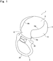
- the illustrated container lid is equipped with a shell 4 made of a thin metal plate, and a grip piece 6 formed from a synthetic resin.
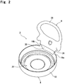
- the shell 4 is composed of a circular top panel wall 8, a cylindrical skirt wall 10 hanging down from the peripheral edge of the top panel wall 8, and a connecting piece 12 extending out from the lower end of the skirt wall 10 in a predetermined region in a circumferential direction.
- a main portion of the top panel wall 8 extends substantially horizontally
- a main portion of the skirt wall 10 extends substantially vertically
- a boundary region between the top panel wall 8 and the skirt wall 10 extends radially outwardly and downwardly in an arcuate shape in Fig. 3 which is a vertical sectional view.
- the connecting piece 12 has a vertical section 12a extending substantially vertically downwardly from the lower end of the skirt wall 10, and an inclined section 12b extending out downwardly, while slanting radially outwardly, in succession to the vertical section 12a.
- notches 16a and 16b are formed in a lower end part of the skirt wall 10.
- Each of the paired scores 18a and 18b has a first part extending from the lower end of the skirt wall 10 to the upper end of the skirt wall 10 in succession to the notch 16a or 16b, a second part extending in a peripheral edge portion of the top panel wall 8 following the first part, and a third part following the second part and further extending out into the skirt wall 10.
- the shell 4 as described above can be integrally formed by applying suitable machining, such as punching or drawing, to a suitable thin metal plate such as a thin aluminum-based alloy plate, a chromic acid-treated thin steel plate, or a thin tin plate.
- the paired scores 18a and 18b can be formed by making a tool act on the thin metal plate from its face or back, thereby reducing its thickness.
- a liner 20 is disposed on an inner surface of the top panel wall 8 of the shell 4.
- the liner 20 is formed by supplying a suitable synthetic resin material, such as flexible polyethylene, to the inner surface of the top panel wall 8 of the shell 4, and embossing the synthetic resin material with a desired shape.
- the liner 20 is disk-shaped as a whole, and has two annular ridges, i.e., an outer annular ridge 22 and an inner annular ridge 24, in a peripheral edge portion thereof.
- the grip piece 6 has a connecting section 26 surrounding the connecting piece 12 of the shell 4 at least partially, and a grip section 28 extending out from the connecting section 26.
- the connecting section 26 of the grip piece 6 surrounds most of the inclined section 12b of the connecting piece 12.
- the so configured grip piece 6 is injection-molded or compression-molded from a suitable synthetic resin material such as polypropylene or polyethylene, preferably a synthetic resin having a Shore D hardness of 55 to 73, with the use of the connecting piece 12 of the shell 4 as a so-called core, and can thereby be coupled to the connecting section 26 simultaneously with the molding.
- the grip piece 6 it is important for the grip piece 6 to include an extension section 30 extending out upwardly over a required length along an inner peripheral surface of the skirt wall 10 from the upper end of an inner surface of the connecting section 26.
- the extension section 30 extends arcuately in a circumferential direction along the inner peripheral surface of the skirt wall 10, and at least an upper end part of the extension section 30, preferably the entire extension section 30, has a thickness of the order of 0.2 to 0.5 mm.
- the circumferential length of the extension section 30 gradually decreases upward, and the extension section 30 is in a trapezoidal shape as a whole.
- the length of upward extension of the extension section 30 be a dimension which establishes such a relation that the upper end part of the extension section 30 is locked to a locking projection of a mouth-neck section of a container on which the container lid 2 is to be mounted.
- the upward extension length of the extension section 30 is advantageously of the order of 5 to 6 mm.
- the connecting section 26 of the grip piece 6 be firmly connected to the connecting piece 12 of the shell 4.
- the connecting section 26 is desirably joined to the connecting piece 12, while the extension section 30 of the grip piece 6 is preferably in a state of non-adhesion or weak adhesion to the inner peripheral surface of the skirt wall 10.
- the extension section 30 To bring the extension section 30 into the state of non-adhesion or weak adhesion to the inner peripheral surface of the skirt wall 10, it is recommendable, for example, to apply a coating, which is non-adherent or weakly adherent to the synthetic resin material making up the grip piece 6, to the site of the thin metal plate forming the shell 4 which the extension section 30 is located to oppose, before molding the grip piece 6 with the use of the connecting piece 12 of the shell 4 as a so-called core. To the site of the connecting piece 12 surrounded by the connecting section 26 of the grip piece 6, it is possible to apply a coating having adhesiveness to the synthetic resin material forming the grip piece 6.
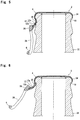
- Fig. 4 shows, together with the container lid 2, a mouth-neck section 32 of a container fitted with the container lid 2.
- the mouth-neck section 32 of the container which can be formed from glass or a suitable synthetic resin such as polyethylene terephthalate, is in a nearly cylindrical shape as a whole, and an upper end part of its outer peripheral surface is formed with an annular locking projection 34 protruding radially outwardly.
- the outer peripheral surface of the locking projection 34 of the mouth-neck section 32 has a diameter gradually increased downward, and is in an arcuate shape in a vertical sectional view.
- a lower surface of the locking projection 34 of the mouth-neck section 32 has a diameter gradually decreased downward, and is in an arcuate shape in a vertical sectional view.
- An arcuate concavity is formed in a region ranging from the lower surface of the locking projection 34 to the outer peripheral surface of the mouth-neck section 32 below this lower surface.
- the container lid 2 To mount the container lid 2 on the mouth-neck section 32 of the container, it is important that the upper end part of the extension section 30 of the grip piece 6 be located above the lower end of the locking projection 34 of the mouth-neck section 32 and opposite the outer peripheral surface of the locking projection 34, with the container lid 2 being fitted onto the mouth-neck section 32 as illustrated in Fig. 4 .
- the upper end of the extension section 30 of the grip piece 6 is located opposite a lower end part of the outer peripheral surface of the locking projection 34 of the mouth-neck section 32.
- the container lid 2 In mounting the container lid 2 on the mouth-neck section 32 of the container filled with beer or a gas-containing liquid such as a carbonated beverage, the container lid 2 is fitted onto the mouth-neck section 32 as illustrated in Fig.
- a finger is hooked over the grip section 28 in the grip piece 6 of the shell 4 to move the grip piece 6 radially outwardly or upwardly, as illustrated in Fig. 6 .
- an undesirable operation is performed, namely, the radially outward or upward movement of the grip piece 6 and the radially inward or downward movement of the grip piece 6 are repeatedly performed, the portion in the connecting piece 12 of the shell 4 which is not surrounded by the connecting section 26 of the grip piece 6, namely, the vertical section 12a or the boundary between the vertical section 12a and the inclined section 12b, is lined with and reinforced with the extension section 30 of the grip piece 6.
- the portion in the connecting piece 12 of the shell 4 which is not surrounded by the connecting section 26 of the grip piece 6 is inhibited from being excessively bent there, and is sufficiently prevented from being broken there.
- the lower end part of the skirt wall 10 is moved away from the locking projection 34 of the mouth-neck section 32 by moving the grip piece 6 radially outwardly or upwardly.
Landscapes
- Engineering & Computer Science (AREA)
- Mechanical Engineering (AREA)
- Closures For Containers (AREA)
Applications Claiming Priority (2)
| Application Number | Priority Date | Filing Date | Title |
|---|---|---|---|
| JP2015192884A JP6576772B2 (ja) | 2015-09-30 | 2015-09-30 | 易開封性容器蓋 |
| PCT/JP2016/076581 WO2017056918A1 (ja) | 2015-09-30 | 2016-09-09 | 易開封性容器蓋 |
Publications (3)
| Publication Number | Publication Date |
|---|---|
| EP3357828A1 EP3357828A1 (en) | 2018-08-08 |
| EP3357828A4 EP3357828A4 (en) | 2019-06-19 |
| EP3357828B1 true EP3357828B1 (en) | 2021-03-31 |
Family
ID=58423371
Family Applications (1)
| Application Number | Title | Priority Date | Filing Date |
|---|---|---|---|
| EP16851092.3A Active EP3357828B1 (en) | 2015-09-30 | 2016-09-09 | Easy-opening container lid |
Country Status (8)
| Country | Link |
|---|---|
| US (1) | US10787296B2 (enExample) |
| EP (1) | EP3357828B1 (enExample) |
| JP (1) | JP6576772B2 (enExample) |
| KR (1) | KR102608647B1 (enExample) |
| CN (1) | CN108137194A (enExample) |
| RU (1) | RU2714334C1 (enExample) |
| TW (1) | TWI676579B (enExample) |
| WO (1) | WO2017056918A1 (enExample) |
Families Citing this family (3)
| Publication number | Priority date | Publication date | Assignee | Title |
|---|---|---|---|---|
| IT202200021786A1 (it) * | 2022-10-21 | 2024-04-21 | Pelliconi & C Spa | Chiusura per contenitori. |
| USD1066016S1 (en) * | 2024-05-07 | 2025-03-11 | Guangdong Yila Technology Co., Ltd. | Bottle cap |
| WO2026083745A1 (ja) * | 2024-10-18 | 2026-04-23 | 日本クロージャー株式会社 | 容器蓋 |
Family Cites Families (13)
| Publication number | Priority date | Publication date | Assignee | Title |
|---|---|---|---|---|
| US2709019A (en) * | 1951-07-23 | 1955-05-24 | Jack N Powell | Opening attachment for bottle caps |
| US3206055A (en) * | 1963-09-03 | 1965-09-14 | Helbling August | Flexible bottle cap opener |
| DE3618178A1 (de) * | 1986-05-30 | 1987-12-03 | Chesoo Domingo Kim | Flaschenverschluss, insbesondere fuer getraenkeflaschen |
| SE8604926D0 (sv) * | 1986-11-17 | 1986-11-18 | Wicanders Kapsyl Ab | Upprivningsbar kapsyl |
| JPH11152159A (ja) * | 1997-11-21 | 1999-06-08 | Fuji Seal Inc | 容易開口容器の蓋体及びその製造方法 |
| CN2369962Y (zh) * | 1999-04-08 | 2000-03-22 | 韦庆林 | 易开瓶盖 |
| CN2618872Y (zh) * | 2003-04-09 | 2004-06-02 | 赵春泽 | 一种易拉瓶盖 |
| JP5038730B2 (ja) | 2007-01-18 | 2012-10-03 | 日本クラウンコルク株式会社 | 易開封性容器蓋 |
| CA2577886C (fr) * | 2007-02-13 | 2015-09-08 | Crealise Conditionnement Inc. | Bouchon sans joint rapporte |
| JP5421816B2 (ja) * | 2010-02-23 | 2014-02-19 | 日本クロージャー株式会社 | 易開封性蓋 |
| US8944264B2 (en) * | 2013-02-04 | 2015-02-03 | World Bottling Cap, LLC | Medical vial cap |
| JP6090914B2 (ja) * | 2013-02-28 | 2017-03-08 | 日本クロージャー株式会社 | 引裂き式容器蓋 |
| JP6356951B2 (ja) * | 2013-08-22 | 2018-07-11 | 日本クロージャー株式会社 | 易開封性容器蓋 |
-
2015
- 2015-09-30 JP JP2015192884A patent/JP6576772B2/ja active Active
-
2016
- 2016-09-09 KR KR1020187011081A patent/KR102608647B1/ko active Active
- 2016-09-09 WO PCT/JP2016/076581 patent/WO2017056918A1/ja not_active Ceased
- 2016-09-09 CN CN201680054837.1A patent/CN108137194A/zh active Pending
- 2016-09-09 RU RU2018113070A patent/RU2714334C1/ru active
- 2016-09-09 EP EP16851092.3A patent/EP3357828B1/en active Active
- 2016-09-09 US US15/758,658 patent/US10787296B2/en active Active
- 2016-09-29 TW TW105131151A patent/TWI676579B/zh active
Non-Patent Citations (1)
| Title |
|---|
| None * |
Also Published As
| Publication number | Publication date |
|---|---|
| EP3357828A1 (en) | 2018-08-08 |
| US20180305089A1 (en) | 2018-10-25 |
| CN108137194A (zh) | 2018-06-08 |
| KR20180063153A (ko) | 2018-06-11 |
| KR102608647B1 (ko) | 2023-11-30 |
| TW201718361A (zh) | 2017-06-01 |
| JP2017065723A (ja) | 2017-04-06 |
| EP3357828A4 (en) | 2019-06-19 |
| US10787296B2 (en) | 2020-09-29 |
| WO2017056918A1 (ja) | 2017-04-06 |
| RU2714334C1 (ru) | 2020-02-14 |
| JP6576772B2 (ja) | 2019-09-18 |
| TWI676579B (zh) | 2019-11-11 |
Similar Documents
| Publication | Publication Date | Title |
|---|---|---|
| CN100515875C (zh) | 带有螺纹颈部的铝容纳器 | |
| EP1939104B1 (en) | Metallic package having a container, a threaded cap and a separate seal member | |
| JP6356951B2 (ja) | 易開封性容器蓋 | |
| US6206222B1 (en) | Resealable closure on seamed can end | |
| CN101835693B (zh) | 具有第一盖件和装配在第一盖件上的第二盖件的瓶盖 | |
| EP3357828B1 (en) | Easy-opening container lid | |
| EP0289022A2 (en) | A system for forming an opening in a container end member | |
| JP5038730B2 (ja) | 易開封性容器蓋 | |
| KR102861280B1 (ko) | 용이 개봉성 용기 뚜껑 | |
| JP2021098553A (ja) | 容器蓋の製造方法 | |
| JP6741444B2 (ja) | 易開封性容器蓋 | |
| JP4585126B2 (ja) | 天面壁が補強された容器蓋 | |
| US20180148219A1 (en) | Lid for a beverage can | |
| JP4383769B2 (ja) | 内圧開放特性を有する容器蓋 | |
| JP4506941B2 (ja) | 容器の開封構造、その製造方法及び製造装置 | |
| JP2026073742A (ja) | 容器蓋 | |
| WO2026083745A1 (ja) | 容器蓋 | |
| JP2015205701A (ja) | 開口容易缶蓋 | |
| JP2007269363A (ja) | キャップ、キャップ付ボトル缶及びキャップ製造方法 | |
| JP2019112148A (ja) | 金属薄板製シェルと合成樹脂製ライナーとを具備する容器蓋 | |
| JP4437935B2 (ja) | ねじ付缶 | |
| GB2532418A (en) | Closure | |
| KR20210087441A (ko) | 캡 | |
| JP2006341860A (ja) | 飲料容器用キャップ | |
| JPH09254976A (ja) | イージーオープン缶蓋 |
Legal Events
| Date | Code | Title | Description |
|---|---|---|---|
| STAA | Information on the status of an ep patent application or granted ep patent |
Free format text: STATUS: THE INTERNATIONAL PUBLICATION HAS BEEN MADE |
|
| PUAI | Public reference made under article 153(3) epc to a published international application that has entered the european phase |
Free format text: ORIGINAL CODE: 0009012 |
|
| STAA | Information on the status of an ep patent application or granted ep patent |
Free format text: STATUS: REQUEST FOR EXAMINATION WAS MADE |
|
| 17P | Request for examination filed |
Effective date: 20180227 |
|
| AK | Designated contracting states |
Kind code of ref document: A1 Designated state(s): AL AT BE BG CH CY CZ DE DK EE ES FI FR GB GR HR HU IE IS IT LI LT LU LV MC MK MT NL NO PL PT RO RS SE SI SK SM TR |
|
| AX | Request for extension of the european patent |
Extension state: BA ME |
|
| DAV | Request for validation of the european patent (deleted) | ||
| DAX | Request for extension of the european patent (deleted) | ||
| A4 | Supplementary search report drawn up and despatched |
Effective date: 20190520 |
|
| RIC1 | Information provided on ipc code assigned before grant |
Ipc: B65D 41/42 20060101AFI20190514BHEP |
|
| STAA | Information on the status of an ep patent application or granted ep patent |
Free format text: STATUS: EXAMINATION IS IN PROGRESS |
|
| 17Q | First examination report despatched |
Effective date: 20200504 |
|
| GRAP | Despatch of communication of intention to grant a patent |
Free format text: ORIGINAL CODE: EPIDOSNIGR1 |
|
| STAA | Information on the status of an ep patent application or granted ep patent |
Free format text: STATUS: GRANT OF PATENT IS INTENDED |
|
| INTG | Intention to grant announced |
Effective date: 20201201 |
|
| GRAS | Grant fee paid |
Free format text: ORIGINAL CODE: EPIDOSNIGR3 |
|
| GRAA | (expected) grant |
Free format text: ORIGINAL CODE: 0009210 |
|
| STAA | Information on the status of an ep patent application or granted ep patent |
Free format text: STATUS: THE PATENT HAS BEEN GRANTED |
|
| AK | Designated contracting states |
Kind code of ref document: B1 Designated state(s): AL AT BE BG CH CY CZ DE DK EE ES FI FR GB GR HR HU IE IS IT LI LT LU LV MC MK MT NL NO PL PT RO RS SE SI SK SM TR |
|
| REG | Reference to a national code |
Ref country code: GB Ref legal event code: FG4D Ref country code: CH Ref legal event code: EP |
|
| REG | Reference to a national code |
Ref country code: DE Ref legal event code: R096 Ref document number: 602016055398 Country of ref document: DE Ref country code: AT Ref legal event code: REF Ref document number: 1376707 Country of ref document: AT Kind code of ref document: T Effective date: 20210415 |
|
| REG | Reference to a national code |
Ref country code: IE Ref legal event code: FG4D |
|
| REG | Reference to a national code |
Ref country code: LT Ref legal event code: MG9D |
|
| PG25 | Lapsed in a contracting state [announced via postgrant information from national office to epo] |
Ref country code: BG Free format text: LAPSE BECAUSE OF FAILURE TO SUBMIT A TRANSLATION OF THE DESCRIPTION OR TO PAY THE FEE WITHIN THE PRESCRIBED TIME-LIMIT Effective date: 20210630 Ref country code: NO Free format text: LAPSE BECAUSE OF FAILURE TO SUBMIT A TRANSLATION OF THE DESCRIPTION OR TO PAY THE FEE WITHIN THE PRESCRIBED TIME-LIMIT Effective date: 20210630 Ref country code: HR Free format text: LAPSE BECAUSE OF FAILURE TO SUBMIT A TRANSLATION OF THE DESCRIPTION OR TO PAY THE FEE WITHIN THE PRESCRIBED TIME-LIMIT Effective date: 20210331 Ref country code: FI Free format text: LAPSE BECAUSE OF FAILURE TO SUBMIT A TRANSLATION OF THE DESCRIPTION OR TO PAY THE FEE WITHIN THE PRESCRIBED TIME-LIMIT Effective date: 20210331 |
|
| PG25 | Lapsed in a contracting state [announced via postgrant information from national office to epo] |
Ref country code: SE Free format text: LAPSE BECAUSE OF FAILURE TO SUBMIT A TRANSLATION OF THE DESCRIPTION OR TO PAY THE FEE WITHIN THE PRESCRIBED TIME-LIMIT Effective date: 20210331 Ref country code: LV Free format text: LAPSE BECAUSE OF FAILURE TO SUBMIT A TRANSLATION OF THE DESCRIPTION OR TO PAY THE FEE WITHIN THE PRESCRIBED TIME-LIMIT Effective date: 20210331 Ref country code: RS Free format text: LAPSE BECAUSE OF FAILURE TO SUBMIT A TRANSLATION OF THE DESCRIPTION OR TO PAY THE FEE WITHIN THE PRESCRIBED TIME-LIMIT Effective date: 20210331 |
|
| REG | Reference to a national code |
Ref country code: NL Ref legal event code: MP Effective date: 20210331 |
|
| REG | Reference to a national code |
Ref country code: AT Ref legal event code: MK05 Ref document number: 1376707 Country of ref document: AT Kind code of ref document: T Effective date: 20210331 |
|
| PG25 | Lapsed in a contracting state [announced via postgrant information from national office to epo] |
Ref country code: AT Free format text: LAPSE BECAUSE OF FAILURE TO SUBMIT A TRANSLATION OF THE DESCRIPTION OR TO PAY THE FEE WITHIN THE PRESCRIBED TIME-LIMIT Effective date: 20210331 Ref country code: SM Free format text: LAPSE BECAUSE OF FAILURE TO SUBMIT A TRANSLATION OF THE DESCRIPTION OR TO PAY THE FEE WITHIN THE PRESCRIBED TIME-LIMIT Effective date: 20210331 Ref country code: NL Free format text: LAPSE BECAUSE OF FAILURE TO SUBMIT A TRANSLATION OF THE DESCRIPTION OR TO PAY THE FEE WITHIN THE PRESCRIBED TIME-LIMIT Effective date: 20210331 Ref country code: EE Free format text: LAPSE BECAUSE OF FAILURE TO SUBMIT A TRANSLATION OF THE DESCRIPTION OR TO PAY THE FEE WITHIN THE PRESCRIBED TIME-LIMIT Effective date: 20210331 Ref country code: CZ Free format text: LAPSE BECAUSE OF FAILURE TO SUBMIT A TRANSLATION OF THE DESCRIPTION OR TO PAY THE FEE WITHIN THE PRESCRIBED TIME-LIMIT Effective date: 20210331 Ref country code: LT Free format text: LAPSE BECAUSE OF FAILURE TO SUBMIT A TRANSLATION OF THE DESCRIPTION OR TO PAY THE FEE WITHIN THE PRESCRIBED TIME-LIMIT Effective date: 20210331 |
|
| PG25 | Lapsed in a contracting state [announced via postgrant information from national office to epo] |
Ref country code: PT Free format text: LAPSE BECAUSE OF FAILURE TO SUBMIT A TRANSLATION OF THE DESCRIPTION OR TO PAY THE FEE WITHIN THE PRESCRIBED TIME-LIMIT Effective date: 20210802 Ref country code: PL Free format text: LAPSE BECAUSE OF FAILURE TO SUBMIT A TRANSLATION OF THE DESCRIPTION OR TO PAY THE FEE WITHIN THE PRESCRIBED TIME-LIMIT Effective date: 20210331 Ref country code: RO Free format text: LAPSE BECAUSE OF FAILURE TO SUBMIT A TRANSLATION OF THE DESCRIPTION OR TO PAY THE FEE WITHIN THE PRESCRIBED TIME-LIMIT Effective date: 20210331 Ref country code: SK Free format text: LAPSE BECAUSE OF FAILURE TO SUBMIT A TRANSLATION OF THE DESCRIPTION OR TO PAY THE FEE WITHIN THE PRESCRIBED TIME-LIMIT Effective date: 20210331 Ref country code: IS Free format text: LAPSE BECAUSE OF FAILURE TO SUBMIT A TRANSLATION OF THE DESCRIPTION OR TO PAY THE FEE WITHIN THE PRESCRIBED TIME-LIMIT Effective date: 20210731 |
|
| REG | Reference to a national code |
Ref country code: DE Ref legal event code: R097 Ref document number: 602016055398 Country of ref document: DE |
|
| PG25 | Lapsed in a contracting state [announced via postgrant information from national office to epo] |
Ref country code: ES Free format text: LAPSE BECAUSE OF FAILURE TO SUBMIT A TRANSLATION OF THE DESCRIPTION OR TO PAY THE FEE WITHIN THE PRESCRIBED TIME-LIMIT Effective date: 20210331 Ref country code: DK Free format text: LAPSE BECAUSE OF FAILURE TO SUBMIT A TRANSLATION OF THE DESCRIPTION OR TO PAY THE FEE WITHIN THE PRESCRIBED TIME-LIMIT Effective date: 20210331 Ref country code: AL Free format text: LAPSE BECAUSE OF FAILURE TO SUBMIT A TRANSLATION OF THE DESCRIPTION OR TO PAY THE FEE WITHIN THE PRESCRIBED TIME-LIMIT Effective date: 20210331 |
|
| PLBE | No opposition filed within time limit |
Free format text: ORIGINAL CODE: 0009261 |
|
| STAA | Information on the status of an ep patent application or granted ep patent |
Free format text: STATUS: NO OPPOSITION FILED WITHIN TIME LIMIT |
|
| 26N | No opposition filed |
Effective date: 20220104 |
|
| REG | Reference to a national code |
Ref country code: CH Ref legal event code: PL |
|
| REG | Reference to a national code |
Ref country code: BE Ref legal event code: MM Effective date: 20210930 |
|
| PG25 | Lapsed in a contracting state [announced via postgrant information from national office to epo] |
Ref country code: IS Free format text: LAPSE BECAUSE OF FAILURE TO SUBMIT A TRANSLATION OF THE DESCRIPTION OR TO PAY THE FEE WITHIN THE PRESCRIBED TIME-LIMIT Effective date: 20210731 Ref country code: MC Free format text: LAPSE BECAUSE OF FAILURE TO SUBMIT A TRANSLATION OF THE DESCRIPTION OR TO PAY THE FEE WITHIN THE PRESCRIBED TIME-LIMIT Effective date: 20210331 |
|
| PG25 | Lapsed in a contracting state [announced via postgrant information from national office to epo] |
Ref country code: LU Free format text: LAPSE BECAUSE OF NON-PAYMENT OF DUE FEES Effective date: 20210909 Ref country code: IE Free format text: LAPSE BECAUSE OF NON-PAYMENT OF DUE FEES Effective date: 20210909 Ref country code: FR Free format text: LAPSE BECAUSE OF NON-PAYMENT OF DUE FEES Effective date: 20210930 Ref country code: BE Free format text: LAPSE BECAUSE OF NON-PAYMENT OF DUE FEES Effective date: 20210930 |
|
| PG25 | Lapsed in a contracting state [announced via postgrant information from national office to epo] |
Ref country code: LI Free format text: LAPSE BECAUSE OF NON-PAYMENT OF DUE FEES Effective date: 20210930 Ref country code: CH Free format text: LAPSE BECAUSE OF NON-PAYMENT OF DUE FEES Effective date: 20210930 |
|
| PG25 | Lapsed in a contracting state [announced via postgrant information from national office to epo] |
Ref country code: CY Free format text: LAPSE BECAUSE OF FAILURE TO SUBMIT A TRANSLATION OF THE DESCRIPTION OR TO PAY THE FEE WITHIN THE PRESCRIBED TIME-LIMIT Effective date: 20210331 |
|
| PG25 | Lapsed in a contracting state [announced via postgrant information from national office to epo] |
Ref country code: HU Free format text: LAPSE BECAUSE OF FAILURE TO SUBMIT A TRANSLATION OF THE DESCRIPTION OR TO PAY THE FEE WITHIN THE PRESCRIBED TIME-LIMIT; INVALID AB INITIO Effective date: 20160909 Ref country code: GR Free format text: LAPSE BECAUSE OF FAILURE TO SUBMIT A TRANSLATION OF THE DESCRIPTION OR TO PAY THE FEE WITHIN THE PRESCRIBED TIME-LIMIT Effective date: 20210331 |
|
| PG25 | Lapsed in a contracting state [announced via postgrant information from national office to epo] |
Ref country code: MK Free format text: LAPSE BECAUSE OF FAILURE TO SUBMIT A TRANSLATION OF THE DESCRIPTION OR TO PAY THE FEE WITHIN THE PRESCRIBED TIME-LIMIT Effective date: 20210331 |
|
| PG25 | Lapsed in a contracting state [announced via postgrant information from national office to epo] |
Ref country code: MT Free format text: LAPSE BECAUSE OF FAILURE TO SUBMIT A TRANSLATION OF THE DESCRIPTION OR TO PAY THE FEE WITHIN THE PRESCRIBED TIME-LIMIT Effective date: 20210331 |
|
| PGFP | Annual fee paid to national office [announced via postgrant information from national office to epo] |
Ref country code: DE Payment date: 20250730 Year of fee payment: 10 |
|
| PGFP | Annual fee paid to national office [announced via postgrant information from national office to epo] |
Ref country code: IT Payment date: 20250825 Year of fee payment: 10 |
|
| PGFP | Annual fee paid to national office [announced via postgrant information from national office to epo] |
Ref country code: GB Payment date: 20250731 Year of fee payment: 10 |
|
| PG25 | Lapsed in a contracting state [announced via postgrant information from national office to epo] |
Ref country code: TR Free format text: LAPSE BECAUSE OF FAILURE TO SUBMIT A TRANSLATION OF THE DESCRIPTION OR TO PAY THE FEE WITHIN THE PRESCRIBED TIME-LIMIT Effective date: 20210331 |