EP3357387A1 - Toilettensitzringanordnung - Google Patents
Toilettensitzringanordnung Download PDFInfo
- Publication number
- EP3357387A1 EP3357387A1 EP17154999.1A EP17154999A EP3357387A1 EP 3357387 A1 EP3357387 A1 EP 3357387A1 EP 17154999 A EP17154999 A EP 17154999A EP 3357387 A1 EP3357387 A1 EP 3357387A1
- Authority
- EP
- European Patent Office
- Prior art keywords
- sensor
- seat ring
- receptacle
- hinge part
- hinge
- Prior art date
- Legal status (The legal status is an assumption and is not a legal conclusion. Google has not performed a legal analysis and makes no representation as to the accuracy of the status listed.)
- Granted
Links
Images



Classifications
-
- A—HUMAN NECESSITIES
- A47—FURNITURE; DOMESTIC ARTICLES OR APPLIANCES; COFFEE MILLS; SPICE MILLS; SUCTION CLEANERS IN GENERAL
- A47K—SANITARY EQUIPMENT; ACCESSORIES THEREFOR, e.g. TOILET ACCESSORIES
- A47K13/00—Seats or covers for all kinds of closets
- A47K13/14—Protecting covers for closet seats
-
- A—HUMAN NECESSITIES
- A47—FURNITURE; DOMESTIC ARTICLES OR APPLIANCES; COFFEE MILLS; SPICE MILLS; SUCTION CLEANERS IN GENERAL
- A47K—SANITARY EQUIPMENT; ACCESSORIES THEREFOR, e.g. TOILET ACCESSORIES
- A47K13/00—Seats or covers for all kinds of closets
- A47K13/12—Hinges
-
- A—HUMAN NECESSITIES
- A47—FURNITURE; DOMESTIC ARTICLES OR APPLIANCES; COFFEE MILLS; SPICE MILLS; SUCTION CLEANERS IN GENERAL
- A47K—SANITARY EQUIPMENT; ACCESSORIES THEREFOR, e.g. TOILET ACCESSORIES
- A47K13/00—Seats or covers for all kinds of closets
- A47K13/04—Buffers for seats
-
- A—HUMAN NECESSITIES
- A47—FURNITURE; DOMESTIC ARTICLES OR APPLIANCES; COFFEE MILLS; SPICE MILLS; SUCTION CLEANERS IN GENERAL
- A47K—SANITARY EQUIPMENT; ACCESSORIES THEREFOR, e.g. TOILET ACCESSORIES
- A47K13/00—Seats or covers for all kinds of closets
- A47K13/24—Parts or details not covered in, or of interest apart from, groups A47K13/02 - A47K13/22
-
- G—PHYSICS
- G01—MEASURING; TESTING
- G01B—MEASURING LENGTH, THICKNESS OR SIMILAR LINEAR DIMENSIONS; MEASURING ANGLES; MEASURING AREAS; MEASURING IRREGULARITIES OF SURFACES OR CONTOURS
- G01B21/00—Measuring arrangements or details thereof, where the measuring technique is not covered by the other groups of this subclass, unspecified or not relevant
- G01B21/02—Measuring arrangements or details thereof, where the measuring technique is not covered by the other groups of this subclass, unspecified or not relevant for measuring length, width, or thickness
Definitions
- the present invention relates to a toilet seat ring assembly according to the preamble of claim 1.
- Toilet seat ring assemblies have become known in the art.
- the EP 2679 127 the Applicant such an arrangement.
- a toilet seat ring assembly comprises a seat ring, a support member, in particular for connecting the toilet seat ring assembly to a toilet, and at least one hinge having a first hinge part and a second hinge part.
- the first hinge part is movably mounted in a partially limited with walls recording such that the hinge or the first hinge part in a weight load of the seat ring shifts in the recording of a starting position in a loading position.
- the receptacle is part of the support element or is firmly connected to this.
- the second hinge part can be pivoted to the first hinge part, so that the seat ring can be pivoted to the support element.
- a contactless sensor is provided with a first sensor part attached to the receptacle and a second sensor part fixed on the first hinge part, with which sensor the displacement of the first hinge part can be detected.
- a sensor signal based on the displacement path can be output.
- a contactless sensor is understood to be a sensor in which the two sensor parts do not have to come into physical or mechanical contact with one another in order to output a sensor signal. This means that the output of a sensor signal is dependent exclusively on the position of the two sensor parts relative to each other, but not on the question of contact.
- a sensor signal can be output in relation to the distance between the two sensor parts, which is advantageous in the signal processing in connection with other systems, such as with a shower toilet.
- the receptacle can be an integral part of the support element.
- the receptacle is formed separately from the support element, which is then firmly connected to the receptacle.
- Support element and recording are then at least two parts.
- two hinges are arranged opposite each other, so that the toilet seat ring is mounted in two places.
- One of the hinges can be designed with and the other without the sensor.
- the hinges are preferably formed substantially identical in construction, and preferably only one of the two hinges are equipped with the contactless sensor.
- the sensor is preferably an inductive sensor or capacitive sensor or an optical sensor or a light barrier.
- the contactless sensor is particularly preferably a Hall sensor, the first sensor part being the active sensor part of the Hall sensor and the second sensor part being the passive sensor part of the Hall sensor.
- the Hall sensor is an analog Hall sensor that outputs an analog sensor signal.
- the use of a digital Hall sensor is also conceivable.
- the active sensor part is preferably arranged on the receptacle and the passive sensor part preferably on the first sensor part. As a result, the active sensor part is not moved back and forth with each operation.
- the reverse arrangement is also conceivable, in which case the passive sensor part is arranged on the receptacle and the active sensor part on the first hinge part.
- the first sensor part and / or the second sensor part is coated with a water-substantially dense protective layer, in particular with a potting compound. This can provide sufficient protection against water or moisture.
- the first sensor part or the passive sensor part is a permanent magnet whose surface to be detected with the first sensor part or the active sensor part is exposed or the surface of which is coated with a plastic layer, in particular of the receptacle or of the hinge part.
- the two sensor parts are preferably arranged on the first hinge part or in the receptacle in such a way that the distance between the sensor parts increases during the movement from the starting position into the end position.
- the contactless sensor then outputs a sensor signal which corresponds to the increasing distance.
- the sensor parts are arranged such that they are under application the seat ring with a weight by the person sitting on the seat ring user will not be subjected to this weight. This means that the sensor parts are not exposed to any mechanical stress from use, that is to say from the user sitting on the seat rings.
- the Toilettensitzringan Alba is characterized very robust.
- the first sensor part is arranged with respect to the movement from the starting position into the end position, which takes place in a downward direction, above the initial position.
- the second sensor part is located below the first sensor part.
- a stop which limits the displacement of the first hinge part in the receptacle, wherein the maximum displacement between starting position and load position is less than 2 millimeters, in particular less than 1 millimeter.
- the first hinge part stands at the stop.
- the stop is for example a constriction of the recording.
- the first hinge part is mounted via a ball joint in the receptacle, wherein the ball joint is preferably designed as a snap hinge. Due to the formation of the connection between the hinge part and receiving as a ball joint has the advantage that a good storage is achieved under the proviso of a simple shift. In addition, the torsional load in the joint can be minimized or the torsional load is not present.
- the ball of the ball joint is vorzuweise arranged on the hinge part and the receptacle comprises the ball socket. Another arrangement is also conceivable.
- the senor is arranged as far away from the ball as possible.
- the walls delimiting the receptacle have at least one slot-like opening which allows the receptacle to have greater elasticity for mounting the first hinge part in the receptacle.
- the slot-like openings increase the flexibility of the receptacle, so that the hinge part is easy to insert into the receptacle.
- a restoring element in particular a compression spring, is also arranged, which returns the first hinge part in the receptacle from the load position to the starting position. With the return element, the first hinge part is held in its initial position.
- the inner walls of the receptacle and the first hinge part are in contact with one another via in each case at least one planar contact surface, such that a rotation of the first hinge part in the receptacle can be prevented.
- the said contact surface is oriented in the direction of movement of the hinge part from the starting position into the load position. That is, the hinge part moves on said contact surface.
- two contact surfaces are arranged opposite each other.
- the second hinge part is in communication with the seat ring.
- the first hinge part and the second hinge part are pivotally connected to each other, so that the seat ring is pivotable to the support member.
- the first hinge part preferably has a bearing section for the second hinge part outside the receptacle. In the bearing section, the second hinge part is then pivotally mounted to the first hinge part.
- the bearing portion can also be arranged in the receptacle, in which case the receptacle must provide access for the second hinge part.
- the second hinge part may also be integrally formed on the seat ring, for example as an opening, into which the first hinge part protrudes, or as a bolt, which projects from the seat ring into the first hinge part.
- At least one of the hinge parts comprises a damping element which dampens the pivoting of the seat ring relative to the support element in at least one direction.
- a toilet lid is also mounted on the hinge.
- the toilet seat ring assembly comprises in the illustrated embodiment a seat ring 1 and a lid 24.
- the toilet seat ring assembly may also be formed without the toilet 3 and without the lid 24.
- FIG. 2 is a perspective view of FIG. 1 shown, wherein the seat ring 1 and the lid 24 are not shown.
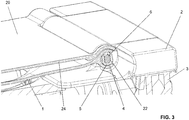
- FIG. 3 is then a sectional view along the section line AA according to the FIG. 1 shown.
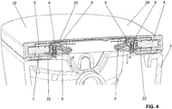
- the FIG. 4 shows a section along the line BB according to the figure 1 .
- the FIG. 5 shows a detailed view of the FIG. 4 ,
- the toilet seat ring assembly comprises a seat ring 1 and a support member 2, which is provided in particular for connection of the toilet seat ring assembly with the toilet 3, and at least one hinge with a first hinge part 5 and a second hinge part 6.
- a first hinge part 5 and a second hinge part 6 In the embodiment shown are two hinges 4, a left hinge and a right hinge, arranged.
- the support element 2 is connectable with its underside with the toilet 3.
- the hinge 4 comprises a first hinge part 5 and a second hinge part 6.
- the first hinge part 5 is movably mounted in a receptacle 8 in support element 2.
- the receptacle 8 is limited with walls 7.
- the first hinge part 5 is mounted in the receptacle 8 such that the hinge 4 or the first hinge part 5 shifts from a weight load of the seat ring 1 in the receptacle 8 from a starting position into a loading position.
- the first hinge part 5 in the starting position.
- the maximum displacement W is a maximum of two millimeters, in particular a maximum of one millimeter.
- the second hinge part 6 is in communication with the seat ring.
- the cover 24 is also mounted on the second hinge part 6.
- the first hinge part and the second hinge part are pivotally connected to each other, so that the seat ring 1 to the support member two is pivotable.
- Another configuration for the connection between the second hinge part 6 and the seat ring 1 or the cover 24 would also be conceivable.
- a contactless sensor 9 is arranged in the area of the receptacle 8.
- the contactless sensor comprises a first sensor part 10 and a second sensor part 11.
- the first sensor part 10 is fixed to the receptacle 8 and the second sensor part 11 is fixed to the first hinge part 5.
- the contactless sensor 9 outputs a sensor signal based on the shift path of the starting position in the load position. The sensor signal thus changes in relation to the displacement path. Based on the output of the sensor signal can be detected whether a user has sat down on the seat ring.
- the non-contact sensor 9 is preferably an inductive sensor or a capacitive sensor.
- the contactless sensor 9 is a Hall sensor.
- the Hall sensor comprises an active sensor part and a passive sensor part, wherein the first sensor part 10 is preferably the active sensor part and the second sensor part 11 is preferably the passive sensor part.
- the active sensor part 10 is arranged in the region of the receptacle and the passive sensor part is arranged in the region of the first hinge part 5.
- the active sensor part comprises, in particular, an electronic printed circuit board, which in the embodiment shown is arranged in a spatial region 25, which is provided outside the receptacle 8.
- the space region 25 is here above the receptacle 8.
- the space region 25 is preferably filled with a potting compound, so that the active sensor part 10 is protected with respect to moisture and other environmental influences.
- the passive sensor part 11 is preferably a permanent magnet whose magnetic field can be detected by the active sensor part 10.
- the active sensor part 10 of the Hall sensor detects the displacement of the permanent magnet relative to the starting position. As a result, the Hall sensor can detect the distance and outputs a corresponding sensor signal.
- the permanent magnet has a surface 13 to be detected with the active sensor part 9.
- the surface 13 may be exposed or it may be coated with a plastic layer.
- the distance between the two sensor parts 10, 11 increases in the movement from the initial position to the end position.
- the active sensor part 10 can be arranged such that it is not acted upon by a weight force when the user sits on the seat ring 1. That is, the sensor parts 10, 11 are arranged such that they are not acted upon by the force acting on the seat ring 1 by applying force to the seat ring 1 with a weight force by the user sitting on the seat ring 1.
- a stop 14 is still provided.
- This stop 14 is in the FIG. 6 shown in more detail.
- the displacement path W of the first hinge part 5 is shown in the receptacle 8.
- the stop 14 provides a stop for the first hinge part 5 in the receptacle 8 and thus limits the maximum displacement path W.
- the maximum displacement W as mentioned above is less than 2 millimeters, in particular less than 1 millimeter.
- the formation of the smallest possible displacement path W is advantageous because the user can be provided with a device that is as rigid as possible, with the contactless sensor 9 equally easy to detect the displacement.
- the first hinge part 5 is mounted via a ball joint 15 in the receptacle 8.
- the ball joint 15 is preferably designed as a snap joint.
- the ball joint 15 lies opposite a bearing section 22, on which the second hinge part 6 engages or is mounted in the first hinge part 5. During the movement from the starting position into the load position, the first hinge part 5 thus pivots about the center of the ball joint.
- the ball 16 of the ball joint 15 is arranged on the first hinge part 5 and the receptacle 8 provides a ball socket 17 in its rear region.
- the walls 7 which define the receptacle 8 preferably comprise at least one slot-like opening 18.
- Such a slot-like opening 18 gives the receptacle 8 a greater elasticity, which facilitates the mounting of the first hinge part 5 in the receptacle 8.
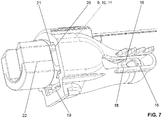
- the slot-like opening 18 is in the FIG. 7 shown.
- a bulge 28 is preferably arranged, which gives the ball socket 17 slightly elastic properties, so that the insertion of the ball 16 is simplified.
- the toilet seat ring assembly further includes a return member 19.
- the return member is a compression spring which returns the first hinge part 5 in the receptacle 8 from the load position to the starting position.
- the compression spring is arranged here below the passive sensor part.
- the inner walls 20 of the receptacle 8 and the first hinge part 3 are in each case via at least one flat contact surface 21, 26 with each other in combination.
- the contact surface 21, 26 is arranged in the embodiment shown laterally to the direction of movement of the first hinge part 5 and is in the FIG. 6 shown. In this case, the first hinge part 5 slides with the contact surface 26 along the contact surface 21 from the starting position into the load position. Due to the flat formations rotation from the first hinge part 5 in the receptacle 8 is prevented.
- the contact surface 26 on the hinge part is likewise flat and has an interruption 27.
- the first hinge part 5 outside the receptacle 8 comprises a bearing section 22 in which the second hinge part 6 is mounted.
- the second hinge part 6 is rotatably mounted in the bearing section 22. It would also be conceivable that the second hinge part 6 is fixedly mounted in the bearing portion 22 and then the seat ring 1 and the cover 24 rotate around the fixed second hinge part 6.
- a damping element 23 can be the pivoting of the seat ring relative to the support element damped in at least one direction.
Landscapes
- Health & Medical Sciences (AREA)
- Public Health (AREA)
- Physics & Mathematics (AREA)
- General Physics & Mathematics (AREA)
- Toilet Supplies (AREA)
Abstract
Description
- Die vorliegende Erfindung betrifft eine Toilettensitzringanordnung nach dem Oberbegriff von Anspruch 1.
- Aus dem Stand der Technik sind Toilettensitzringanordnungen bekannt geworden. Beispielsweise offenbart die
EP 2679 127 der Anmelderin eine derartige Anordnung. - Aus der
JP 2005-021713 - Folglich ist es eine Aufgabe der vorliegenden Erfindung, eine Toilettensitzringanordnung anzugeben, welche die Nachteile des Standes der Technik überwindet. Insbesondere soll die Toilettensitzringanordnung zuverlässig die Benutzung erkennen und bezüglich äusseren Einflüssen möglichst robust sein.
- Diese Aufgabe löst der Gegenstand vom Anspruch 1. Demgemäss umfasst eine Toilettensitzringanordnung einen Sitzring, ein Supportelement, insbesondere zur Verbindung der Toilettensitzringanordnung mit einer Toilette, und mindestens ein Scharnier mit einem ersten Scharnierteil und einem zweiten Scharnierteil. Das erste Scharnierteil ist beweglich in einer teilweise mit Wänden begrenzten Aufnahme derart gelagert, dass sich das Scharnier bzw. das erste Scharnierteil bei einer Gewichtsbelastung des Sitzrings in der Aufnahme von einer Ausgangslage in eine Belastungslage verschiebt. Die Aufnahme ist Teil des Supportelementes oder ist mit diesem fest verbindbar. Das zweite Scharnierteil ist zum ersten Scharnierteil verschwenkbar, so dass der Sitzring zum Supportelement verschwenkbar ist. Im Bereich der Aufnahme ist ein kontaktloser Sensor mit einem an der Aufnahme festgelegten ersten Sensorteil und einem am ersten Scharnierteil festgelegten zweiten Sensorteil vorgesehen, mit welchem Sensor das Verschieben des ersten Scharnierteils erfassbar ist. Mit dem kontaktlosen Sensor ist ein Sensorsignal basierend auf dem Verschiebeweg ausgebbar.
- Unter einem kontaktlosen Sensor wird ein Sensor verstanden, bei welchem die beiden Sensorteile nicht miteinander in physischen oder mechanischen Kontakt kommen müssen, um ein Sensorsignal auszugeben. Das heisst die Ausgabe von einem Sensorsignal ist ausschliesslich von der Lage der beiden Sensorteile relativ zueinander abhängig, nicht aber von der Frage des Kontaktes. Durch den Einsatz eines kontaktlosen Sensors kann eine Anordnung erreicht werden, welche bezüglich Korrosion robuster ausgebildet ist.
- Zudem kann ein Sensorsignal in Relation zum Abstand der beiden Sensorteile ausgegeben werden, was bei der Signalverarbeitung im Zusammenhang mit anderen Systemen, wie beispielsweise mit einem Dusch-WC, vorteilhaft ist.
- Die Aufnahme kann ein integraler Bestandteil des Supportelementes sein. Alternativ ist die Aufnahme separat vom Supportelement ausgebildet, welches dann mit der Aufnahme fest verbindbar ist. Supportelement und Aufnahme sind dann mindestens zwei Teile.
- Vorzugsweise sind zwei Scharniere gegenüber einander angeordnet, so dass der Toilettensitzring an zwei Orten gelagert ist. Eines der Scharniere kann dabei mit und das andere ohne den Sensor ausgebildet sein. Das heisst, dass die Scharniere vorzugsweise im Wesentlichen baugleich ausgebildet sind, und vorzugsweise nur eines der beiden Scharniere mit dem kontaktlosen Sensor ausgerüstet sind.
- Es ist auch denkbar, dass bei beiden Scharnieren ein Sensor angeordnet ist, wobei es auch hier vorteilhaft ist, die beiden Scharniere baugleich auszubilden.
- Vorzugsweise ist der Sensor ein induktiver Sensor oder kapazitiver Sensor oder ein optischer Sensor oder eine Lichtschranke.
- Besonders bevorzugt ist der kontaktlose Sensor ein Hallsensor, wobei das erste Sensorteil der aktive Sensorteil des Hallsensors und das zweite Sensorteil der passive Sensorteil des Hallsensors ist.
- Besonders bevorzugt ist der Hallsensor ein analoger Hallsensor, der ein analoges Sensorsignal ausgibt. Der Einsatz eines digitalen Hallsensors ist auch denkbar.
- Der aktive Sensorteil ist vorzugsweise an der Aufnahme und der passive Sensorteil vorzugsweise am ersten Sensorteil angeordnet. Hierdurch wird das aktive Sensorteil nicht bei jeder Betätigung hin und her bewegt. Die umgekehrte Anordnung ist auch denkbar, wobei dann der passive Sensorteil an der Aufnahme und der aktive Sensorteil am ersten Scharnierteil anordnet ist.
- Besonders bevorzugt ist das erste Sensorteil und/oder das zweite Sensorteil mit einer bezüglich Wasser im Wesentlichen dichten Schutzschicht, insbesondere mit einer Vergussmasse, überzogen. Hierdurch kann ein ausreichender Schutz gegen Wasser oder Feuchtigkeit bereitgestellt werden.
- Besonders bevorzugt ist das erste Sensorteil bzw. das passive Sensorteil ein Permanentmagnet, dessen mit dem ersten Sensorteil bzw. dem aktiven Sensorteil zu erfassende Oberfläche frei liegt oder dessen Oberfläche mit einer Kunststoffschicht, insbesondere von der Aufnahme oder vom Scharnierteil, überzogen ist.
- Vorzugsweise sind die beiden Sensorteile, unabhängig von der Art des Sensors, derart am ersten Scharnierteil bzw. in der Aufnahme angeordnet, dass bei der Bewegung von der Ausgangslage in die Endlage die Distanz zwischen den Sensorteilen sich vergrössert. Der kontaktlose Sensor gibt dann ein Sensorsignal aus, welches der sich vergrössernden Distanz entspricht.
- Vorzugsweise sind die Sensorteile derart angeordnet sind, dass diese bei Beaufschlagung des Sitzrings mit einer Gewichtskraft durch den sich auf den Sitzring sitzenden Benutzer nicht mit dieser Gewichtskraft beaufschlagt werden. Das heisst, dass die Sensorteile keiner mechanischen Belastung durch den Gebrauch, sprich durch den sich auf den Sitzringen setzenden Benutzer, ausgesetzt sind. Die Toilettensitzringanordnung ist dadurch sehr robust ausgebildet.
- Vorzugsweise ist das erste Sensorteil bezüglich der Bewegung von der Ausgangslage in die Endlage, welche in eine Richtung nach unten erfolgt, oberhalb der Ausgangslage angeordnet ist. Dabei liegt das zweite Sensorteil unterhalb des ersten Sensorteils.
- Vorzugsweise ist, insbesondere in der Aufnahme, ein Anschlag bereitgestellt, welcher die Verschiebung des ersten Scharnierteils in der Aufnahme begrenzt, wobei der maximale Verschiebeweg zwischen Ausgangslage und Belastungslage kleiner als 2 Millimetern, insbesondere kleiner als 1 Millimeter, ist. Das erste Scharnierteil steht dabei am Anschlag an. Der Anschlag ist beispielsweise eine Verengung der Aufnahme.
- Vorzugsweise ist das erste Scharnierteil über ein Kugelgelenk in der Aufnahme gelagert, wobei das Kugelgelenk vorzugsweise als Schnappgelenk ausgebildet ist. Durch die Ausbildung der Verbindung zwischen Scharnierteil und Aufnahme als Kugelgelenk ergeht der Vorteil, dass eine gute Lagerung unter der Massgabe einer einfachen Verschiebung erreicht wird. Zudem kann die Torsionsbelastung im Gelenk minimiert werden bzw. die Torsionsbelastung ist nicht vorhanden.
- Die Kugel des Kugelgelenkes ist vorzuweise am Scharnierteil angeordnet und die Aufnahme umfasst die Kugelpfanne. Eine andere Anordnung ist ebenfalls denkbar.
- Besonders bevorzugt ist der Sensor möglichst weit von der Kugel weg angeordnet.
- Vorzugsweise weisen die die Aufnahme begrenzenden Wände mindestens eine schlitzartige Öffnung auf, welche der Aufnahme eine grössere Elastizität zur Montage des ersten Scharnierteils in der Aufnahme erlauben. Die Schlitzartigen Öffnungen erhöhen die Flexibilität der Aufnahme, so dass das Scharnierteil einfach in die Aufnahme einsetzbar ist.
- Vorzugsweise ist weiterhin ein Rückstellelement, insbesondere eine Druckfeder, angeordnet, welches das erste Scharnierteil in der Aufnahme von der Belastungslage in die Ausgangslage zurückstellt. Mit dem Rückstellelement wird das erste Scharnierteil in seiner Ausgangslage gehalten.
- Vorzugsweise stehen die Innenwände der Aufnahme und das erste Scharnierteil über jeweils mindestens eine ebene Kontaktfläche miteinander in Kontakt, derart, dass eine Drehung vom ersten Scharnierteil in der Aufnahme verhinderbar ist.
- Die besagte Kontaktfläche ist in Richtung der Bewegung des Scharnierteils von der Ausgangslage in die Belastungslage orientiert. Das heisst, das Scharnierteil bewegt sich auf der besagten Kontaktfläche.
- Vorzugsweise sind jeweils zwei Kontaktflächen gegenüber einander angeordnet.
- Vorzugsweise steht das zweite Scharnierteil mit dem Sitzring in Verbindung. Das erste Scharnierteil und das zweite Scharnierteil stehen verschwenkbar miteinander in Verbindung, so dass der Sitzring zum Supportelement verschwenkbar ist. Vorzugsweise weist das erste Scharnierteil ausserhalb der Aufnahme einen Lagerabschnitt für das zweite Scharnierteil auf. Im Lagerabschnitt ist das zweite Scharnierteil dann verschwenkbar zum ersten Scharnierteil gelagert. Der Lagerabschnitt kann auch in der Aufnahme angeordnet sein, wobei dann die Aufnahme einen Zugang für das zweite Scharnierteil bereitstellen muss.
- Alternativ kann das zweite Scharnierteil auch am Sitzring angeformt sein, beispielsweise als Öffnung, in die das erste Scharnierteil einragt, oder als Bolzen, welcher vom Sitzring in das erste Scharniteil einragt.
- Vorzugsweise umfasst mindestens eines der Scharnierteile ein Dämpfungselement, welches die Verschwenkung des Sitzrings relativ zum Supportelement in mindestens eine Richtung dämpft.
- Vorzugsweise ist über das Scharnier auch ein Toilettendeckel gelagert.
- Weitere Ausführungsformen sind in den abhängigen Ansprüchen angegeben.
- Bevorzugte Ausführungsformen der Erfindung werden im Folgenden anhand der Zeichnungen beschrieben, die lediglich zur Erläuterung dienen und nicht einschränkend auszulegen sind. In den Zeichnungen zeigen:
- Fig. 1
- eine perspektivische Ansicht einer Toilette mit einer Sitzringanordnung gemäss einer Ausführungsform der vorliegenden Erfindung;
- Fig. 2
- die Ansicht nach
Figur 1 ohne Toilettendeckel und Sitzring; - Fig. 3
- eine Schnittdarstellung durch das Scharnier der Sitzringanordnung nach
Figur 1 ; - Fig. 4
- eine Schnittdarstellung durch das Scharnier der Sitzringanordnung nach den vorhergehenden Figuren;
- Fig. 5
- eine Detailansicht der
Figur 4 ; - Fig. 6
- eine weitere Schnittdarstellung durch das Scharnier der Sitzringanordnung nach den vorhergehenden Figuren; und
- Fig. 7
- eine Detailansicht des Scharniers.
- In der
Figur 1 wird die Kombination einer Toilette 3 mit einer Toilettensitzringanordnung gezeigt. Die Toilettensitzringanordnung umfasst in der gezeigten Ausführungsform einen Sitzring 1 und einen Deckel 24. Die Toilettensitzringanordnung kann auch ohne die Toilette 3 und ohne den Deckel 24 ausgebildet sein. - In der
Figur 2 wird eine perspektivische Darstellung derFigur 1 gezeigt, wobei der Sitzring 1 und der Deckel 24 nicht dargestellt sind. - In der
Figur 3 wird so dann eine Schnittdarstellung entlang der Schnittlinie A-A gemäss derFigur 1 gezeigt. DieFigur 4 zeigt einen Schnitt entlang der Linie B-B gemäss derFigur 1 . DieFigur 5 zeigt eine Detailansicht von derFigur 4 . - Die Toilettensitzringanordnung umfasst einen Sitzring 1 und ein Supportelement 2, das insbesondere zur Verbindung der Toilettensitzringanordnung mit der Toilette 3 vorgesehen ist, und mindestens ein Scharnier mit einem ersten Scharnierteil 5 und einem zweiten Scharnierteil 6. In der gezeigten Ausführungsform sind jeweils zwei Scharniere 4, ein linkes Scharnier und ein rechtes Scharnier, angeordnet.
- Das Supportelement 2 ist mit seiner Unterseite mit der Toilette 3 verbindbar.
- Unter Bezugnahme auf die
Figuren 4 und5 wird nun die Ausbildung der Toilettensitzringanordnung genauer erläutert. Das Scharnier 4 umfasst ein erstes Scharnierteil 5 und ein zweites Scharnierteil 6. Das erste Scharnierteil 5 ist beweglich in einer Aufnahme 8 in Supportelement 2 gelagert. Die Aufnahme 8 ist dabei mit Wänden 7 begrenzt. Das erste Scharnierteil 5 ist dabei derart in der Aufnahme 8 gelagert, dass sich das Scharnier 4 beziehungsweise das erste Scharnierteil 5 von einer Gewichtsbelastung des Sitzrings 1 in der Aufnahme 8 von einer Ausgangslage in eine Belastungslage verschiebt. In denFiguren 4 und5 befindet sich das erste Scharnierteil 5 in der Ausgangslage. Sobald eine Kraft auf den Sitzring wirkt, wird das erste Scharnierteil 5 und auch das zweite Scharnierteil 6 in Richtung des Pfeils P von der Ausgangslage in die Belastungslage bewegt. Dabei verschiebt sich das erste Scharnierteil und das zweite Scharnierteil 6 nach unten. Der maximale Verschiebeweg W beträgt maximal zwei Millimeter, insbesondere maximal einen Millimeter. - Das zweite Scharnierteil 6 steht mit dem Sitzring in Verbindung. In der gezeigten Ausführungsform ist zudem auch noch der Deckel 24 am zweiten Scharnierteil 6 gelagert. In der gezeigten Ausführungsform steht das erste Scharnierteil und das zweite Scharnierteil verschwenkbar miteinander in Verbindung, so dass der Sitzring 1 zum Supportelement zwei verschwenkbar ist. Eine andere Konfiguration für die Verbindung zwischen dem zweiten Scharniteil 6 und den Sitzring 1 bzw. dem Deckel 24 wäre auch denkbar.
- Im Bereich der Aufnahme 8 ist ein kontaktloser Sensor 9 angeordnet. Der kontaktlose Sensor umfasst ein erstes Sensorteil 10 und ein zweites Sensorteil 11. Das erste Sensorteil 10 ist an der Aufnahme 8 festgelegt und das zweite Sensorteil 11 ist am ersten Scharnierteil 5 befestigt. Mit dem Sensor 9 ist das Verschieben des ersten Scharnierteils 6 bezüglich der Aufnahme 8 erfassbar. Der kontaktlose Sensor 9 gibt dabei ein Sensorsignal basierend auf dem Verschiebweg der Ausgangslage in die Belastungslage aus. Das Sensorsignal verändert sich also in Relation zum Verschiebeweg. Anhand der Ausgabe des Sensorsignals kann erfasst werden, ob ein Benutzer sich auf den Sitzring gesetzt hat.
- Der kontaktlose Sensor 9 ist vorzugsweise ein induktiver Sensor oder ein kapazitiver Sensor.
- Besonders bevorzugt ist der kontaktlose Sensor 9 ein Hallsensor. Der Hallsensor umfasst einen aktiven Sensorteil und einen passiven Sensorteil, wobei das erste Sensorteil 10 vorzugsweise der aktive Sensorteil und das zweite Sensorteil 11 vorzugsweise der passive Sensorteil ist. In der gezeigten Ausführungsform ist der aktive Sensorteil 10 im Bereich der Aufnahme angeordnet und der passive Sensorteil ist im Bereich des ersten Scharnierteils 5 angeordnet. Das aktive Sensorteil umfasst insbesondere eine elektronische Leiterplatine, welche in der gezeigten Ausführungsform in einem Raumbereich 25 angeordnet ist, welcher ausserhalb der Aufnahme 8 vorgesehen ist. Der Raumbereich 25 liegt hier oberhalb der Aufnahme 8. Der Raumbereich 25 wird vorzugsweise mit einer Vergussmasse befüllt, so dass der aktive Sensorteil 10 bezüglich Feuchtigkeit und anderen Umgebungseinflüssen geschützt ist.
- Der passive Sensorteil 11 ist vorzugsweise ein Permanentmagnet, dessen Magnetfeld durch den aktiven Sensorteil 10 erfasst werden kann. Der aktive Sensorteil 10 des Hallsensor detektiert die Verschiebung des Permanentmagneten relativ zur Ausgangslage. Hierdurch kann der Hallsensor die Distanz erfassen und gibt ein entsprechendes Sensorsignal aus.
- Der Permanentmagnet weist dabei eine mit dem aktiven Sensorteil 9 zu erfassende Oberfläche 13 auf. Die Oberfläche 13 kann dabei frei liegen oder sie kann mit einer Kunststoffschicht überzogen sein.
- Von der
Figur 5 wird klar, dass sich bei der Bewegung von der Ausgangslage in die Endlage die Distanz zwischen den beiden Sensorteilen 10, 11 vergrössert. Diese Anordnung hat den Vorteil, dass der aktive Sensorteil 10 derart angeordnet werden kann, dass dieser nicht mit einer Gewichtskraft, wenn sich der Benutzer auf den Sitzring 1 setzt, beaufschlägt wird. Das heisst, die Sensorteile 10, 11 sind derart angeordnet, dass diese bei Beaufschlagung des Sitzrings 1 mit einer Gewichtskraft durch den sich auf den Sitzring 1 setzenden Benutzer nicht mit dieser Gewichtskraft beaufschlagt werden. - In der Aufnahme 8 ist weiterhin ein Anschlag 14 bereitgestellt. Dieser Anschlag 14 wird in der
Figur 6 genauer gezeigt. In derFigur 6 ist zudem der Verschiebeweg W des ersten Scharnierteils 5 in der Aufnahme 8 dargestellt. Der Anschlag 14 stellt einen Anschlag für das erste Scharnierteil 5 in der Aufnahme 8 bereit und begrenzt somit den maximalen Verschiebeweg W. Vorzugsweise ist der maximale Verschiebeweg W wie oben erwähnt kleiner als 2 Millimeter insbesondere kleiner als 1 Millimeter. Die Ausbildung des möglichst kleinen Verschiebeweges W ist vorteilhaft, weil dem Benutzer eine möglichst starre Vorrichtung bereitgestellt werden kann, wobei mit dem kontaktlosen Sensor 9 gleichermassen die Verschiebung einfach zu erfassen ist. - Von der
Figur 5 wird gezeigt, dass das erste Scharnierteil 5 über ein Kugelgelenk 15 in der Aufnahme 8 gelagert ist. Das Kugelgelenk 15 ist vorzugsweise als Schnappgelenk ausgebildet. Das Kugelgelenk 15 liegt dabei gegenüber einem Lagerabschnitt 22, an welchem das zweite Scharnierteil 6 in das erste Scharnierteil 5 eingreift bzw. gelagert ist. Bei der Bewegung von der Ausgangslage in die Belastungslage verschwenkt sich somit das erste Scharnierteil 5 um das Zentrum des Kugelgelenkes. - In der gezeigten Ausführungsform ist die Kugel 16 des Kugelgelenkes 15 am ersten Scharnierteil 5 angeordnet und die Aufnahme 8 stellt in ihrem hinteren Bereich eine Kugelpfanne 17 bereit. Die Wände 7, welche die Aufnahme 8 begrenzen umfassen vorzugsweise mindestens eine schlitzartige Öffnung 18. Eine derartige schlitzartige Öffnung 18 verleiht der Aufnahme 8 eine grössere Elastizität, was die Montage des ersten Scharnierteils 5 in der Aufnahme 8 erleichtert. Die schlitzartige Öffnung 18 wird in der
Figur 7 gezeigt. - Eine umgekehrte Anordnung von Kugel 16 und Kugelpfanne 17 wäre auch denkbar.
- Im Bereich der Kugelpfanne 17 ist vorzugsweise eine Ausbuchtung 28 angeordnet, welche der Kugelpfanne 17 leicht federelastische Eigenschaften verleiht, so dass das Einschieben der Kugel 16 vereinfacht wird.
- Die Toilettensitzringanordnung umfasst weiterhin ein Rückstellelement 19. In der gezeigten Ausführungsform ist das Rückstellelement eine Druckfeder, welche das erste Scharnierteil 5 in der Aufnahme 8 von der Belastungslage in die Ausgangslage zurückstellt. Die Druckfeder ist hier unterhalb des passiven Sensorteils angeordnet.
- Die Innenwände 20 der Aufnahme 8 und das erste Scharnierteil 3 stehen jeweils über mindestens eine ebene Kontaktfläche 21, 26 mit einander in Verbindung. Die Kontaktfläche 21, 26 ist in der gezeigten Ausführungsform seitlich zur Bewegungsrichtung des ersten Scharnierteils 5 angeordnet und wird in der
Figur 6 gezeigt. Dabei gleitet das erste Scharnierteil 5 mit der Kontaktfläche 26 entlang der Kontaktfläche 21 von der Ausgangslage in die Belastungslage. Aufgrund der ebenen Ausbildungen wird eine Drehung vom ersten Scharnierteil 5 in der Aufnahme 8 verhindert. Die Kontaktfläche 26 am Scharnierteil ist ebenfalls eben ausgebildet und weist eine Unterbrechung 27 auf. - Von der
Figur 4 wird zudem klar, dass in der gezeigten Ausführungsform nur eines der beiden Scharniere mit dem kontaktlosen Sensor 9 ausgebildet ist. Das andere der beiden Scharniere ist zwar baugleich ausgebildet, weist aber nicht den Sensor auf. Alternativerweise kann auch an beiden Scharnieren jeweils ein Sensor angeordnet werden. - Wie oben bereits erläutert umfasst das erste Scharnierteil 5 ausserhalb der Aufnahme 8 einen Lagerabschnitt 22, in welchem das zweite Scharnierteil 6 gelagert ist. In der gezeigten Ausführungsform ist das zweite Scharnierteil 6 im Lagerabschnitt 22 drehbar gelagert. Es wäre aber auch denkbar, dass das zweite Scharnierteil 6 fest im Lagerabschnitt 22 gelagert ist und das dann der Sitzring 1 beziehungsweise der Deckel 24 sich um den festgelagerten zweiten Scharnierteil 6 herumdrehen.
- Weiterhin umfasst mindestens eines der Scharnierteile 5, 6, je das zweite Scharnierteil 6, ein Dämpfungselement 23. Mit dem Dämpfungselement 23 lässt sich die Verschwenkung des Sitzringes relativ zum Supportelement in mindestens eine Richtung dämpfen.
BEZUGSZEICHENLISTE 1 Sitzring 25 Raumbereich 2 Supportelement 26 ebene Kontaktfläche 3 Toilette 27 Unterbrechung 4 Scharnier 28 Ausbuchtung 5 erstes Scharnierteil 6 zweites Scharnierteil W Verschiebeweg 7 Wand P Verschieberichtung 8 Aufnahme 9 kontakloser Sensor 10 erster Sensorteil 11 zweiter Sensorteil 12 Schutzschicht 13 Oberfläche 14 Anschlag 15 Kugelgelenk 16 Kugel 17 Kugelpfanne 18 schlitzartige Öffnung 19 Rückstellelement 20 Innenwände 21 Kontaktfläche 22 Lagerabschnitt 23 Dämpfungselement 24 Deckel
Claims (15)
- Toilettensitzringanordnung umfassend
einen Sitzring (1),
ein Supportelement (2), insbesondere zur Verbindung der Toilettensitzringanordnung mit einer Toilette (3),
und mindestens ein Scharnier (4) mit einem ersten Scharnierteil (5) und einem zweiten Scharnierteil (6),
wobei das erste Scharnierteil (5) beweglich in einer teilweise mit Wänden (7) begrenzten Aufnahme (8) gelagert ist, derart, dass sich das Scharnier (4) bzw. das erste Scharnierteil (5) bei einer Gewichtsbelastung des Sitzrings (1) in der Aufnahme (8) von einer Ausgangslage in eine Belastungslage verschiebt,
wobei die Aufnahme (8) Teil des Supportelementes (2) ist oder mit diesem fest verbindbar ist, und
wobei das zweite Scharnierteil (6) zum ersten Scharnierteil (6) verschwenkbar ist, so dass der Sitzring (1) zum Supportelement (2) verschwenkbar ist,
dadurch gekennzeichnet, dass im Bereich der Aufnahme (8) ein kontaktloser Sensor (9) mit einem an der Aufnahme (8) festgelegten ersten Sensorteil (10) und einem am ersten Scharnierteil (5) festgelegten zweiten Sensorteil (11) vorgesehen ist, mit welchem Sensor (9) das Verschieben des ersten Scharnierteils (5) erfassbar ist und Sensorsignal basierend auf dem Verschiebeweg ausgebbar ist. - Toilettensitzringanordnung nach Anspruch 1, dadurch gekennzeichnet, dass der kontaktlose Sensor (9) ein induktiver Sensor oder kapazitiver Sensor ist.
- Toilettensitzringanordnung nach Anspruch 1 oder 2, dadurch gekennzeichnet, dass der kontaktlose Sensor (9) ein Hallsensor mit einem aktiven Sensorteil und einem passiven Sensorteil ist, wobei das erste Sensorteil (10) der aktive Sensorteil und das zweite Sensorteil (11) der passive Sensorteil ist.
- Toilettensitzringanordnung nach einem der vorhergehenden Ansprüche, dadurch gekennzeichnet, dass das erste Sensorteil (10) und/oder das zweite Sensorteil (11) mit einer bezüglich Wasser im Wesentlichen dichten Schutzschicht (12), insbesondere mit einer Vergussmasse, überzogen sind.
- Toilettensitzringanordnung nach Anspruch 2 bis 4, dadurch gekennzeichnet, dass das zweite Sensorteil (11) bzw. das passive Sensorteil ein Permanentmagnet ist, dessen mit dem ersten Sensorteil (10) bzw. dem aktiven Sensorteil (9) zu erfassende Oberfläche (13) frei liegt oder dessen Oberfläche (13) mit einer Kunststoffschicht, insbesondere von der Aufnahme (8) oder vom Scharnierteil (5), überzogen ist.
- Toilettensitzringanordnung nach einem der vorhergehenden Ansprüche, dadurch gekennzeichnet, dass bei der Bewegung von der Ausgangslage in die Endlage die Distanz zwischen den Sensorteilen (10, 11) sich vergrössert.
- Toilettensitzringanordnung nach einem der vorhergehenden Ansprüchen, dadurch gekennzeichnet, dass die Sensorteile (10, 11) derart angeordnet sind, dass diese bei Beaufschlagung des Sitzrings (2) mit einer Gewichtskraft durch den sich auf den Sitzring (2) sitzenden Benutzer nicht mit dieser Gewichtskraft beaufschlagt werden.
- Toilettensitzringanordnung nach einem der vorhergehenden Ansprüche, dadurch gekennzeichnet, dass bezüglich der Bewegung von der Ausgangslage in die Endlage, welche in eine Richtung nach unten erfolgt, das erste Sensorteil (10) oberhalb der Ausgangslage angeordnet ist.
- Toilettensitzringanordnung nach einem der vorhergehenden Ansprüche, dadurch gekennzeichnet, dass, insbesondere in der Aufnahme (8), ein Anschlag (14) bereitgestellt ist, welcher die Verschiebung des ersten Scharnierteils (5) in der Aufnahme (8) begrenzt, wobei der maximale Verschiebeweg (W) zwischen Ausgangslage und Belastungslage kleiner als 2 Millimetern, insbesondere kleiner als 1 Millimeter, ist.
- Toilettensitzringanordnung nach einem der vorhergehenden Ansprüche, dadurch gekennzeichnet, dass das erste Scharnierteil (5) über ein Kugelgelenk (15) in der Aufnahme (8) gelagert ist, wobei das Kugelgelenk (15) vorzugsweise als Schnappgelenk ausgebildet ist.
- Toilettensitzringanordnung nach Anspruch 9 oder 10, dadurch gekennzeichnet, dass die die Aufnahme (8) begrenzenden Wände (7) mindestens eine schlitzartige Öffnung (18) umfassen, welche der Aufnahme (8) eine grössere Elastizität zur Montage des ersten Scharnierteils (5) in der Aufnahme (8) bereitstellt.
- Toilettensitzringanordnung nach einem der vorhergehenden Ansprüche, dadurch gekennzeichnet, dass weiterhin ein Rückstellelement (19), insbesondere eine Druckfeder, angeordnet ist, welches das erste Scharnierteil (5) in der Aufnahme (8) von der Belastungslage in die Ausgangslage zurückstellt.
- Toilettensitzringanordnung nach einem der vorhergehenden Ansprüche, dadurch gekennzeichnet, dass die Innenwände (20) der Aufnahme (8) und das erste Scharnierteil (5) über jeweils mindestens eine ebene Kontaktfläche (21, 26) miteinander in Kontakt stehen, derart, dass eine Drehung vom ersten Scharnierteil (5) in der Aufnahme (8) verhinderbar ist.
- Toilettensitzringanordnung nach einem der vorhergehenden Ansprüche, dadurch gekennzeichnet, dass das erste Scharnierteil (5) ausserhalb der Aufnahme (8) einen Lagerabschnitt (22) für das zweite Scharnierteil (6) aufweist.
- Toilettensitzringanordnung nach einem der vorhergehenden Ansprüche, dadurch gekennzeichnet, dass zwei Scharniere (4) angeordnet sind, wobei die Scharniere (4) vorzugsweise im Wesentlichen baugleich ausgebildet sind, und wobei vorzugsweise nur eines der beiden Scharniere (4) mit dem kontaktlosen Sensor (9) ausgerüstet sind.
Priority Applications (3)
| Application Number | Priority Date | Filing Date | Title |
|---|---|---|---|
| ES17154999T ES2839253T3 (es) | 2017-02-07 | 2017-02-07 | Conjunto de anillo de asiento de inodoro |
| EP17154999.1A EP3357387B1 (de) | 2017-02-07 | 2017-02-07 | Toilettensitzringanordnung |
| CN201810064398.3A CN108392128B (zh) | 2017-02-07 | 2018-01-23 | 便桶座圈装置 |
Applications Claiming Priority (1)
| Application Number | Priority Date | Filing Date | Title |
|---|---|---|---|
| EP17154999.1A EP3357387B1 (de) | 2017-02-07 | 2017-02-07 | Toilettensitzringanordnung |
Publications (2)
| Publication Number | Publication Date |
|---|---|
| EP3357387A1 true EP3357387A1 (de) | 2018-08-08 |
| EP3357387B1 EP3357387B1 (de) | 2020-11-11 |
Family
ID=58009678
Family Applications (1)
| Application Number | Title | Priority Date | Filing Date |
|---|---|---|---|
| EP17154999.1A Active EP3357387B1 (de) | 2017-02-07 | 2017-02-07 | Toilettensitzringanordnung |
Country Status (3)
| Country | Link |
|---|---|
| EP (1) | EP3357387B1 (de) |
| CN (1) | CN108392128B (de) |
| ES (1) | ES2839253T3 (de) |
Cited By (3)
| Publication number | Priority date | Publication date | Assignee | Title |
|---|---|---|---|---|
| CN112914407A (zh) * | 2019-12-06 | 2021-06-08 | 吉博力国际股份公司 | 用于安装马桶支撑件的铰链 |
| EP3991621A1 (de) * | 2020-10-27 | 2022-05-04 | Geberit International AG | Intelligenter nfc-toilettenaufsatz |
| WO2022115060A1 (en) * | 2020-11-30 | 2022-06-02 | Iz Yapi Malzeme Ve Ekipmanlari Sanayi Ve Ticaret Anonim Sirketi | An easy detachable cover assembly improved to be used in a sanitary furniture item |
Citations (5)
| Publication number | Priority date | Publication date | Assignee | Title |
|---|---|---|---|---|
| JPH0469099U (de) * | 1990-10-24 | 1992-06-18 | ||
| JP2005021713A (ja) | 2004-09-10 | 2005-01-27 | Matsushita Electric Ind Co Ltd | 衛生洗浄装置 |
| EP2679127A1 (de) | 2012-06-28 | 2014-01-01 | Geberit International AG | WC-Bauteile und WC mit lösbarem Scharnier |
| WO2014147928A1 (ja) * | 2013-03-21 | 2014-09-25 | パナソニック株式会社 | 衛生洗浄装置 |
| CN104523194A (zh) * | 2014-12-31 | 2015-04-22 | 浙江特洁尔智能洁具有限公司 | 一种智能坐便器的落座感应装置 |
Family Cites Families (3)
| Publication number | Priority date | Publication date | Assignee | Title |
|---|---|---|---|---|
| US4133061A (en) * | 1977-05-31 | 1979-01-09 | Hurd Everett C | Easily disassembled hinge assembly |
| CN201026161Y (zh) * | 2006-08-04 | 2008-02-27 | 松下电器产业株式会社 | 着座检测开关和卫生洗净装置 |
| CN202960356U (zh) * | 2012-12-03 | 2013-06-05 | 厦门豪帝卫浴工业有限公司 | 一键按压式锌合金合页铰链 |
-
2017
- 2017-02-07 EP EP17154999.1A patent/EP3357387B1/de active Active
- 2017-02-07 ES ES17154999T patent/ES2839253T3/es active Active
-
2018
- 2018-01-23 CN CN201810064398.3A patent/CN108392128B/zh active Active
Patent Citations (5)
| Publication number | Priority date | Publication date | Assignee | Title |
|---|---|---|---|---|
| JPH0469099U (de) * | 1990-10-24 | 1992-06-18 | ||
| JP2005021713A (ja) | 2004-09-10 | 2005-01-27 | Matsushita Electric Ind Co Ltd | 衛生洗浄装置 |
| EP2679127A1 (de) | 2012-06-28 | 2014-01-01 | Geberit International AG | WC-Bauteile und WC mit lösbarem Scharnier |
| WO2014147928A1 (ja) * | 2013-03-21 | 2014-09-25 | パナソニック株式会社 | 衛生洗浄装置 |
| CN104523194A (zh) * | 2014-12-31 | 2015-04-22 | 浙江特洁尔智能洁具有限公司 | 一种智能坐便器的落座感应装置 |
Cited By (5)
| Publication number | Priority date | Publication date | Assignee | Title |
|---|---|---|---|---|
| CN112914407A (zh) * | 2019-12-06 | 2021-06-08 | 吉博力国际股份公司 | 用于安装马桶支撑件的铰链 |
| EP3831258A1 (de) * | 2019-12-06 | 2021-06-09 | Geberit International AG | Scharnier zur lagerung einer toilettenauflage |
| CN112914407B (zh) * | 2019-12-06 | 2023-10-03 | 吉博力国际股份公司 | 用于安装马桶支撑件的铰链 |
| EP3991621A1 (de) * | 2020-10-27 | 2022-05-04 | Geberit International AG | Intelligenter nfc-toilettenaufsatz |
| WO2022115060A1 (en) * | 2020-11-30 | 2022-06-02 | Iz Yapi Malzeme Ve Ekipmanlari Sanayi Ve Ticaret Anonim Sirketi | An easy detachable cover assembly improved to be used in a sanitary furniture item |
Also Published As
| Publication number | Publication date |
|---|---|
| CN108392128A (zh) | 2018-08-14 |
| EP3357387B1 (de) | 2020-11-11 |
| CN108392128B (zh) | 2021-10-08 |
| ES2839253T3 (es) | 2021-07-05 |
Similar Documents
| Publication | Publication Date | Title |
|---|---|---|
| DE29705392U1 (de) | Türstopperanordnung | |
| EP3535822B1 (de) | Schaltschrank mit einer montageplattenanordnung | |
| DE102012016541A1 (de) | Geschirrspüler | |
| DE102008033232A1 (de) | Steckerteil für eine optische Steckverbindung | |
| EP3357387B1 (de) | Toilettensitzringanordnung | |
| EP1541906B1 (de) | Dichtung zwischen einander gegenüberliegenden Dichtflächen | |
| DE102012102188B4 (de) | Steckverbinder und Verfahren zur Montage eines Steckverbinders | |
| EP3135524A1 (de) | Tankanschluss eines kraftfahrzeuges | |
| EP3993200A1 (de) | Installationsdose für eine hohlwandinstallation | |
| DE4418238A1 (de) | Mehrgelenkiges Scharnier | |
| DE69800329T2 (de) | Gehäuse für elektrische Geräte mit abnehmbarem Deckel und Deckelbefestigungsanordnung | |
| DE102018217316A1 (de) | Tülle | |
| EP1338741A2 (de) | Scharnierverbindung und damit ausgetatteter Behälter | |
| DE102010060082A1 (de) | Tragprofil für ein Tragarmsystem | |
| DE20309732U1 (de) | Lüftungsdüse für ein Kraftfahrzeug | |
| EP3575637B1 (de) | Kraftfahrzeug-antriebsanordnung | |
| DE102015221581B4 (de) | Kameramodul | |
| DE102019200029A1 (de) | Winkelsensor | |
| EP3424401A1 (de) | Vorrichtung zur abgabe von reinigungsmittel | |
| DE202012101166U1 (de) | Vorrichtung zur Aufnahme von Brief-, Paket- und/oder Warensendungen | |
| EP3787135B1 (de) | Verteilerschrank | |
| DE60203732T2 (de) | Gegengewicht-scharnier-vorrichtung mit vertikalbewegung für eine tür | |
| DE102014107831B4 (de) | Klappdeckel | |
| DE102014107828A1 (de) | Klappdeckel | |
| DE3628473A1 (de) | Wandanschlussbogen |
Legal Events
| Date | Code | Title | Description |
|---|---|---|---|
| PUAI | Public reference made under article 153(3) epc to a published international application that has entered the european phase |
Free format text: ORIGINAL CODE: 0009012 |
|
| STAA | Information on the status of an ep patent application or granted ep patent |
Free format text: STATUS: THE APPLICATION HAS BEEN PUBLISHED |
|
| AK | Designated contracting states |
Kind code of ref document: A1 Designated state(s): AL AT BE BG CH CY CZ DE DK EE ES FI FR GB GR HR HU IE IS IT LI LT LU LV MC MK MT NL NO PL PT RO RS SE SI SK SM TR |
|
| AX | Request for extension of the european patent |
Extension state: BA ME |
|
| STAA | Information on the status of an ep patent application or granted ep patent |
Free format text: STATUS: REQUEST FOR EXAMINATION WAS MADE |
|
| 17P | Request for examination filed |
Effective date: 20190108 |
|
| RBV | Designated contracting states (corrected) |
Designated state(s): AL AT BE BG CH CY CZ DE DK EE ES FI FR GB GR HR HU IE IS IT LI LT LU LV MC MK MT NL NO PL PT RO RS SE SI SK SM TR |
|
| GRAJ | Information related to disapproval of communication of intention to grant by the applicant or resumption of examination proceedings by the epo deleted |
Free format text: ORIGINAL CODE: EPIDOSDIGR1 |
|
| STAA | Information on the status of an ep patent application or granted ep patent |
Free format text: STATUS: GRANT OF PATENT IS INTENDED |
|
| GRAP | Despatch of communication of intention to grant a patent |
Free format text: ORIGINAL CODE: EPIDOSNIGR1 |
|
| INTG | Intention to grant announced |
Effective date: 20200610 |
|
| GRAS | Grant fee paid |
Free format text: ORIGINAL CODE: EPIDOSNIGR3 |
|
| GRAA | (expected) grant |
Free format text: ORIGINAL CODE: 0009210 |
|
| STAA | Information on the status of an ep patent application or granted ep patent |
Free format text: STATUS: THE PATENT HAS BEEN GRANTED |
|
| AK | Designated contracting states |
Kind code of ref document: B1 Designated state(s): AL AT BE BG CH CY CZ DE DK EE ES FI FR GB GR HR HU IE IS IT LI LT LU LV MC MK MT NL NO PL PT RO RS SE SI SK SM TR |
|
| REG | Reference to a national code |
Ref country code: GB Ref legal event code: FG4D Free format text: NOT ENGLISH |
|
| REG | Reference to a national code |
Ref country code: CH Ref legal event code: EP |
|
| REG | Reference to a national code |
Ref country code: AT Ref legal event code: REF Ref document number: 1332648 Country of ref document: AT Kind code of ref document: T Effective date: 20201115 |
|
| REG | Reference to a national code |
Ref country code: DE Ref legal event code: R096 Ref document number: 502017008109 Country of ref document: DE |
|
| REG | Reference to a national code |
Ref country code: IE Ref legal event code: FG4D Free format text: LANGUAGE OF EP DOCUMENT: GERMAN |
|
| REG | Reference to a national code |
Ref country code: CH Ref legal event code: NV Representative=s name: ISLER AND PEDRAZZINI AG, CH |
|
| REG | Reference to a national code |
Ref country code: NL Ref legal event code: FP |
|
| PG25 | Lapsed in a contracting state [announced via postgrant information from national office to epo] |
Ref country code: RS Free format text: LAPSE BECAUSE OF FAILURE TO SUBMIT A TRANSLATION OF THE DESCRIPTION OR TO PAY THE FEE WITHIN THE PRESCRIBED TIME-LIMIT Effective date: 20201111 Ref country code: PT Free format text: LAPSE BECAUSE OF FAILURE TO SUBMIT A TRANSLATION OF THE DESCRIPTION OR TO PAY THE FEE WITHIN THE PRESCRIBED TIME-LIMIT Effective date: 20210311 Ref country code: NO Free format text: LAPSE BECAUSE OF FAILURE TO SUBMIT A TRANSLATION OF THE DESCRIPTION OR TO PAY THE FEE WITHIN THE PRESCRIBED TIME-LIMIT Effective date: 20210211 Ref country code: GR Free format text: LAPSE BECAUSE OF FAILURE TO SUBMIT A TRANSLATION OF THE DESCRIPTION OR TO PAY THE FEE WITHIN THE PRESCRIBED TIME-LIMIT Effective date: 20210212 Ref country code: FI Free format text: LAPSE BECAUSE OF FAILURE TO SUBMIT A TRANSLATION OF THE DESCRIPTION OR TO PAY THE FEE WITHIN THE PRESCRIBED TIME-LIMIT Effective date: 20201111 |
|
| PG25 | Lapsed in a contracting state [announced via postgrant information from national office to epo] |
Ref country code: SE Free format text: LAPSE BECAUSE OF FAILURE TO SUBMIT A TRANSLATION OF THE DESCRIPTION OR TO PAY THE FEE WITHIN THE PRESCRIBED TIME-LIMIT Effective date: 20201111 Ref country code: BG Free format text: LAPSE BECAUSE OF FAILURE TO SUBMIT A TRANSLATION OF THE DESCRIPTION OR TO PAY THE FEE WITHIN THE PRESCRIBED TIME-LIMIT Effective date: 20210211 Ref country code: PL Free format text: LAPSE BECAUSE OF FAILURE TO SUBMIT A TRANSLATION OF THE DESCRIPTION OR TO PAY THE FEE WITHIN THE PRESCRIBED TIME-LIMIT Effective date: 20201111 Ref country code: IS Free format text: LAPSE BECAUSE OF FAILURE TO SUBMIT A TRANSLATION OF THE DESCRIPTION OR TO PAY THE FEE WITHIN THE PRESCRIBED TIME-LIMIT Effective date: 20210311 Ref country code: LV Free format text: LAPSE BECAUSE OF FAILURE TO SUBMIT A TRANSLATION OF THE DESCRIPTION OR TO PAY THE FEE WITHIN THE PRESCRIBED TIME-LIMIT Effective date: 20201111 |
|
| REG | Reference to a national code |
Ref country code: LT Ref legal event code: MG9D |
|
| PG25 | Lapsed in a contracting state [announced via postgrant information from national office to epo] |
Ref country code: HR Free format text: LAPSE BECAUSE OF FAILURE TO SUBMIT A TRANSLATION OF THE DESCRIPTION OR TO PAY THE FEE WITHIN THE PRESCRIBED TIME-LIMIT Effective date: 20201111 |
|
| REG | Reference to a national code |
Ref country code: ES Ref legal event code: FG2A Ref document number: 2839253 Country of ref document: ES Kind code of ref document: T3 Effective date: 20210705 |
|
| PG25 | Lapsed in a contracting state [announced via postgrant information from national office to epo] |
Ref country code: SK Free format text: LAPSE BECAUSE OF FAILURE TO SUBMIT A TRANSLATION OF THE DESCRIPTION OR TO PAY THE FEE WITHIN THE PRESCRIBED TIME-LIMIT Effective date: 20201111 Ref country code: RO Free format text: LAPSE BECAUSE OF FAILURE TO SUBMIT A TRANSLATION OF THE DESCRIPTION OR TO PAY THE FEE WITHIN THE PRESCRIBED TIME-LIMIT Effective date: 20201111 Ref country code: SM Free format text: LAPSE BECAUSE OF FAILURE TO SUBMIT A TRANSLATION OF THE DESCRIPTION OR TO PAY THE FEE WITHIN THE PRESCRIBED TIME-LIMIT Effective date: 20201111 Ref country code: LT Free format text: LAPSE BECAUSE OF FAILURE TO SUBMIT A TRANSLATION OF THE DESCRIPTION OR TO PAY THE FEE WITHIN THE PRESCRIBED TIME-LIMIT Effective date: 20201111 Ref country code: EE Free format text: LAPSE BECAUSE OF FAILURE TO SUBMIT A TRANSLATION OF THE DESCRIPTION OR TO PAY THE FEE WITHIN THE PRESCRIBED TIME-LIMIT Effective date: 20201111 |
|
| REG | Reference to a national code |
Ref country code: DE Ref legal event code: R097 Ref document number: 502017008109 Country of ref document: DE |
|
| PG25 | Lapsed in a contracting state [announced via postgrant information from national office to epo] |
Ref country code: DK Free format text: LAPSE BECAUSE OF FAILURE TO SUBMIT A TRANSLATION OF THE DESCRIPTION OR TO PAY THE FEE WITHIN THE PRESCRIBED TIME-LIMIT Effective date: 20201111 |
|
| PLBE | No opposition filed within time limit |
Free format text: ORIGINAL CODE: 0009261 |
|
| STAA | Information on the status of an ep patent application or granted ep patent |
Free format text: STATUS: NO OPPOSITION FILED WITHIN TIME LIMIT |
|
| PG25 | Lapsed in a contracting state [announced via postgrant information from national office to epo] |
Ref country code: MC Free format text: LAPSE BECAUSE OF FAILURE TO SUBMIT A TRANSLATION OF THE DESCRIPTION OR TO PAY THE FEE WITHIN THE PRESCRIBED TIME-LIMIT Effective date: 20201111 |
|
| 26N | No opposition filed |
Effective date: 20210812 |
|
| PG25 | Lapsed in a contracting state [announced via postgrant information from national office to epo] |
Ref country code: AL Free format text: LAPSE BECAUSE OF FAILURE TO SUBMIT A TRANSLATION OF THE DESCRIPTION OR TO PAY THE FEE WITHIN THE PRESCRIBED TIME-LIMIT Effective date: 20201111 Ref country code: LU Free format text: LAPSE BECAUSE OF NON-PAYMENT OF DUE FEES Effective date: 20210207 |
|
| PG25 | Lapsed in a contracting state [announced via postgrant information from national office to epo] |
Ref country code: SI Free format text: LAPSE BECAUSE OF FAILURE TO SUBMIT A TRANSLATION OF THE DESCRIPTION OR TO PAY THE FEE WITHIN THE PRESCRIBED TIME-LIMIT Effective date: 20201111 |
|
| PG25 | Lapsed in a contracting state [announced via postgrant information from national office to epo] |
Ref country code: IE Free format text: LAPSE BECAUSE OF NON-PAYMENT OF DUE FEES Effective date: 20210207 |
|
| PG25 | Lapsed in a contracting state [announced via postgrant information from national office to epo] |
Ref country code: IS Free format text: LAPSE BECAUSE OF FAILURE TO SUBMIT A TRANSLATION OF THE DESCRIPTION OR TO PAY THE FEE WITHIN THE PRESCRIBED TIME-LIMIT Effective date: 20210311 |
|
| P01 | Opt-out of the competence of the unified patent court (upc) registered |
Effective date: 20230516 |
|
| PG25 | Lapsed in a contracting state [announced via postgrant information from national office to epo] |
Ref country code: CY Free format text: LAPSE BECAUSE OF FAILURE TO SUBMIT A TRANSLATION OF THE DESCRIPTION OR TO PAY THE FEE WITHIN THE PRESCRIBED TIME-LIMIT Effective date: 20201111 |
|
| PG25 | Lapsed in a contracting state [announced via postgrant information from national office to epo] |
Ref country code: HU Free format text: LAPSE BECAUSE OF FAILURE TO SUBMIT A TRANSLATION OF THE DESCRIPTION OR TO PAY THE FEE WITHIN THE PRESCRIBED TIME-LIMIT; INVALID AB INITIO Effective date: 20170207 |
|
| PG25 | Lapsed in a contracting state [announced via postgrant information from national office to epo] |
Ref country code: MK Free format text: LAPSE BECAUSE OF FAILURE TO SUBMIT A TRANSLATION OF THE DESCRIPTION OR TO PAY THE FEE WITHIN THE PRESCRIBED TIME-LIMIT Effective date: 20201111 |
|
| REG | Reference to a national code |
Ref country code: NL Ref legal event code: PD Owner name: GEBERIT HOLDING AG; CH Free format text: DETAILS ASSIGNMENT: CHANGE OF OWNER(S), MERGE; FORMER OWNER NAME: GEBERIT INTERNATIONAL AG Effective date: 20240604 Ref country code: NL Ref legal event code: HC Owner name: GEBERIT INTERNATIONAL AG; CH Free format text: DETAILS ASSIGNMENT: CHANGE OF OWNER(S), CHANGE OF OWNER(S) NAME; FORMER OWNER NAME: GEBERIT HOLDING AG Effective date: 20240604 |
|
| PG25 | Lapsed in a contracting state [announced via postgrant information from national office to epo] |
Ref country code: TR Free format text: LAPSE BECAUSE OF FAILURE TO SUBMIT A TRANSLATION OF THE DESCRIPTION OR TO PAY THE FEE WITHIN THE PRESCRIBED TIME-LIMIT Effective date: 20201111 |
|
| REG | Reference to a national code |
Ref country code: BE Ref legal event code: PD Owner name: GEBERIT HOLDING AG; CH Free format text: DETAILS ASSIGNMENT: CHANGE OF OWNER(S), MERGE; FORMER OWNER NAME: GEBERIT INTERNATIONAL AG Effective date: 20240528 Ref country code: BE Ref legal event code: HC Owner name: GEBERIT INTERNATIONAL AG; CH Free format text: DETAILS ASSIGNMENT: CHANGE OF OWNER(S), CHANGE OF OWNER(S) NAME; FORMER OWNER NAME: GEBERIT HOLDING AG Effective date: 20240528 |
|
| PG25 | Lapsed in a contracting state [announced via postgrant information from national office to epo] |
Ref country code: MT Free format text: LAPSE BECAUSE OF FAILURE TO SUBMIT A TRANSLATION OF THE DESCRIPTION OR TO PAY THE FEE WITHIN THE PRESCRIBED TIME-LIMIT Effective date: 20201111 |
|
| REG | Reference to a national code |
Ref country code: AT Ref legal event code: PC Ref document number: 1332648 Country of ref document: AT Kind code of ref document: T Owner name: GEBERIT INTERNATIONAL AG, CH Effective date: 20241118 |
|
| REG | Reference to a national code |
Ref country code: ES Ref legal event code: PC2A Owner name: GEBERIT INTERNATIONAL AG Effective date: 20250206 |
|
| PGFP | Annual fee paid to national office [announced via postgrant information from national office to epo] |
Ref country code: ES Payment date: 20250331 Year of fee payment: 9 |
|
| REG | Reference to a national code |
Ref country code: CH Ref legal event code: U11 Free format text: ST27 STATUS EVENT CODE: U-0-0-U10-U11 (AS PROVIDED BY THE NATIONAL OFFICE) Effective date: 20260301 |
|
| PGFP | Annual fee paid to national office [announced via postgrant information from national office to epo] |
Ref country code: NL Payment date: 20260218 Year of fee payment: 10 |
|
| PGFP | Annual fee paid to national office [announced via postgrant information from national office to epo] |
Ref country code: GB Payment date: 20260219 Year of fee payment: 10 |
|
| PGFP | Annual fee paid to national office [announced via postgrant information from national office to epo] |
Ref country code: DE Payment date: 20260218 Year of fee payment: 10 |
|
| PGFP | Annual fee paid to national office [announced via postgrant information from national office to epo] |
Ref country code: AT Payment date: 20260219 Year of fee payment: 10 |
|
| PGFP | Annual fee paid to national office [announced via postgrant information from national office to epo] |
Ref country code: BE Payment date: 20260218 Year of fee payment: 10 Ref country code: IT Payment date: 20260219 Year of fee payment: 10 |
|
| PGFP | Annual fee paid to national office [announced via postgrant information from national office to epo] |
Ref country code: FR Payment date: 20260218 Year of fee payment: 10 |
|
| PGFP | Annual fee paid to national office [announced via postgrant information from national office to epo] |
Ref country code: CZ Payment date: 20260129 Year of fee payment: 10 Ref country code: CH Payment date: 20260301 Year of fee payment: 10 |