EP3357309B1 - Calculateur de véhicule - Google Patents
Calculateur de véhicule Download PDFInfo
- Publication number
- EP3357309B1 EP3357309B1 EP16763196.9A EP16763196A EP3357309B1 EP 3357309 B1 EP3357309 B1 EP 3357309B1 EP 16763196 A EP16763196 A EP 16763196A EP 3357309 B1 EP3357309 B1 EP 3357309B1
- Authority
- EP
- European Patent Office
- Prior art keywords
- housing
- sensor
- vehicle
- vehicle sensor
- control device
- Prior art date
- Legal status (The legal status is an assumption and is not a legal conclusion. Google has not performed a legal analysis and makes no representation as to the accuracy of the status listed.)
- Active
Links
- 239000004020 conductor Substances 0.000 claims description 8
- 238000005259 measurement Methods 0.000 claims description 7
- 238000004519 manufacturing process Methods 0.000 description 3
- 230000005540 biological transmission Effects 0.000 description 2
- 230000007547 defect Effects 0.000 description 2
- 230000001419 dependent effect Effects 0.000 description 2
- 238000000034 method Methods 0.000 description 2
- 238000007789 sealing Methods 0.000 description 2
- 230000009471 action Effects 0.000 description 1
- 238000009530 blood pressure measurement Methods 0.000 description 1
- 238000004891 communication Methods 0.000 description 1
- 238000013461 design Methods 0.000 description 1
- 238000011156 evaluation Methods 0.000 description 1
- 239000012530 fluid Substances 0.000 description 1
- 238000010438 heat treatment Methods 0.000 description 1
- 238000009434 installation Methods 0.000 description 1
- 230000007774 longterm Effects 0.000 description 1
- 239000000463 material Substances 0.000 description 1
- 239000012528 membrane Substances 0.000 description 1
- 230000008569 process Effects 0.000 description 1
- 230000009467 reduction Effects 0.000 description 1
- 230000001105 regulatory effect Effects 0.000 description 1
Images
Classifications
-
- G—PHYSICS
- G01—MEASURING; TESTING
- G01L—MEASURING FORCE, STRESS, TORQUE, WORK, MECHANICAL POWER, MECHANICAL EFFICIENCY, OR FLUID PRESSURE
- G01L19/00—Details of, or accessories for, apparatus for measuring steady or quasi-steady pressure of a fluent medium insofar as such details or accessories are not special to particular types of pressure gauges
- G01L19/14—Housings
- G01L19/148—Details about the circuit board integration, e.g. integrated with the diaphragm surface or encapsulation
-
- H—ELECTRICITY
- H05—ELECTRIC TECHNIQUES NOT OTHERWISE PROVIDED FOR
- H05K—PRINTED CIRCUITS; CASINGS OR CONSTRUCTIONAL DETAILS OF ELECTRIC APPARATUS; MANUFACTURE OF ASSEMBLAGES OF ELECTRICAL COMPONENTS
- H05K5/00—Casings, cabinets or drawers for electric apparatus
- H05K5/0026—Casings, cabinets or drawers for electric apparatus provided with connectors and printed circuit boards [PCB], e.g. automotive electronic control units
- H05K5/0043—Casings, cabinets or drawers for electric apparatus provided with connectors and printed circuit boards [PCB], e.g. automotive electronic control units comprising a frame housing mating with two lids wherein the PCB is flat mounted on the frame housing
-
- G—PHYSICS
- G01—MEASURING; TESTING
- G01L—MEASURING FORCE, STRESS, TORQUE, WORK, MECHANICAL POWER, MECHANICAL EFFICIENCY, OR FLUID PRESSURE
- G01L19/00—Details of, or accessories for, apparatus for measuring steady or quasi-steady pressure of a fluent medium insofar as such details or accessories are not special to particular types of pressure gauges
- G01L19/0061—Electrical connection means
- G01L19/0084—Electrical connection means to the outside of the housing
-
- G—PHYSICS
- G01—MEASURING; TESTING
- G01L—MEASURING FORCE, STRESS, TORQUE, WORK, MECHANICAL POWER, MECHANICAL EFFICIENCY, OR FLUID PRESSURE
- G01L19/00—Details of, or accessories for, apparatus for measuring steady or quasi-steady pressure of a fluent medium insofar as such details or accessories are not special to particular types of pressure gauges
- G01L19/14—Housings
- G01L19/147—Details about the mounting of the sensor to support or covering means
-
- H—ELECTRICITY
- H05—ELECTRIC TECHNIQUES NOT OTHERWISE PROVIDED FOR
- H05K—PRINTED CIRCUITS; CASINGS OR CONSTRUCTIONAL DETAILS OF ELECTRIC APPARATUS; MANUFACTURE OF ASSEMBLAGES OF ELECTRICAL COMPONENTS
- H05K5/00—Casings, cabinets or drawers for electric apparatus
- H05K5/0017—Casings, cabinets or drawers for electric apparatus with operator interface units
-
- H—ELECTRICITY
- H05—ELECTRIC TECHNIQUES NOT OTHERWISE PROVIDED FOR
- H05K—PRINTED CIRCUITS; CASINGS OR CONSTRUCTIONAL DETAILS OF ELECTRIC APPARATUS; MANUFACTURE OF ASSEMBLAGES OF ELECTRICAL COMPONENTS
- H05K5/00—Casings, cabinets or drawers for electric apparatus
- H05K5/02—Details
- H05K5/0204—Mounting supporting structures on the outside of casings
-
- H—ELECTRICITY
- H05—ELECTRIC TECHNIQUES NOT OTHERWISE PROVIDED FOR
- H05K—PRINTED CIRCUITS; CASINGS OR CONSTRUCTIONAL DETAILS OF ELECTRIC APPARATUS; MANUFACTURE OF ASSEMBLAGES OF ELECTRICAL COMPONENTS
- H05K5/00—Casings, cabinets or drawers for electric apparatus
- H05K5/02—Details
- H05K5/0247—Electrical details of casings, e.g. terminals, passages for cables or wiring
-
- B—PERFORMING OPERATIONS; TRANSPORTING
- B60—VEHICLES IN GENERAL
- B60Y—INDEXING SCHEME RELATING TO ASPECTS CROSS-CUTTING VEHICLE TECHNOLOGY
- B60Y2400/00—Special features of vehicle units
- B60Y2400/30—Sensors
- B60Y2400/306—Pressure sensors
-
- B—PERFORMING OPERATIONS; TRANSPORTING
- B60—VEHICLES IN GENERAL
- B60Y—INDEXING SCHEME RELATING TO ASPECTS CROSS-CUTTING VEHICLE TECHNOLOGY
- B60Y2410/00—Constructional features of vehicle sub-units
- B60Y2410/115—Electric wiring; Electric connectors
-
- H—ELECTRICITY
- H05—ELECTRIC TECHNIQUES NOT OTHERWISE PROVIDED FOR
- H05K—PRINTED CIRCUITS; CASINGS OR CONSTRUCTIONAL DETAILS OF ELECTRIC APPARATUS; MANUFACTURE OF ASSEMBLAGES OF ELECTRICAL COMPONENTS
- H05K5/00—Casings, cabinets or drawers for electric apparatus
- H05K5/02—Details
- H05K5/03—Covers
-
- H—ELECTRICITY
- H05—ELECTRIC TECHNIQUES NOT OTHERWISE PROVIDED FOR
- H05K—PRINTED CIRCUITS; CASINGS OR CONSTRUCTIONAL DETAILS OF ELECTRIC APPARATUS; MANUFACTURE OF ASSEMBLAGES OF ELECTRICAL COMPONENTS
- H05K5/00—Casings, cabinets or drawers for electric apparatus
- H05K5/06—Hermetically-sealed casings
- H05K5/061—Hermetically-sealed casings sealed by a gasket held between a removable cover and a body, e.g. O-ring, packing
Definitions
- the invention relates to a vehicle control device according to the preamble of claim 1.
- Vehicle control units are used to monitor and control a large number of functions of a vehicle. These work partly autonomously and partly dependent on driver intervention.
- the individual vehicle control units are usually specialized in one or a few functions, such as the braking system. This means that there are typically a number of different vehicle control units in a vehicle.
- the invention described here is basically suitable for different types of vehicle control devices, but is described here as an example for brake control devices.
- a vehicle control device is equipped or connected with suitable vehicle sensors.
- the vehicle sensors are electrically connected to the vehicle control device or to an electronic circuit or printed circuit board arranged in the interior of a housing of the vehicle control device.
- the at least one vehicle sensor is preferably designed as a pressure sensor.
- it is a pressure sensor of a pneumatic system, for example a pneumatic brake system.
- the vehicle sensors are designed as separate units and only have an electrical cable connection to the vehicle control unit or its electronic circuit connected.
- the disadvantage here is that the sensor has to have a separate housing along with a corresponding fastening and, above all, that an electrical cable connection suffers in its reliability in the long term due to vibrations and the like. Cabling is also complex, especially when there are several sensors.
- the vehicle sensor is arranged directly on the electronic circuit or the electronic circuit board, so that there is a permanent electrical connection.
- the corresponding measured value for example an air pressure or the like, or the measurement object, such as a pressure medium, must then be transported to the vehicle sensor, for example by means of lines, deflectors, hoses or the like.
- suitable bushings and connections for, for example, a pressure hose or the like must be provided.
- This solution is complex, especially when arranging several sensors.
- DE 10 2013 220 091 A1 discloses a pressure sensor for measuring the pressure of a fluid, in particular a brake pressure sensor, with a pressure transducer which comprises a pressure port having a pressure channel and a measuring membrane which has pressure-intensive elements on the side facing away from the pressure channel, and a circuit board with evaluation electronics arranged thereon.
- the pressure sensor is characterized by a circuit board carrier which has several electrical conductors which electrically connect the pressure-sensitive elements to the circuit board, the electrical conductors being electrically connected to the circuit board by being press-fitted.
- DE 100 37 842 A1 discloses a pressure control device for wheel slip-regulated hydraulic motor vehicle brake systems, which is particularly suitable for automatic braking intervention, with a first housing for receiving a plurality of pressure medium channels which are in communication with a plurality of pressure control valves and pressure sensors in the first housing, with a second housing arranged on the first housing for receiving electrical and / or electronic components connected to the pressure control valves. At least one of the pressure sensor elements is combined with a heating element to form an assembly that can be handled independently.
- EP 1 152 231 A2 discloses an electronic control device with a housing and a cover which contains a printed circuit board which is equipped with components and with at least one pressure sensor.
- a snorkel is used to supply pressure to the pressure sensor, the lower part of which surrounds the pressure sensor and the edge of which is sealed against the circuit board.
- the control device can be used in particular in so-called mechatronics in which both electrical and mechanical signals are processed.
- a pressure and temperature sensor with a housing with supply of the pressure medium, a pressure measuring cell, a printed circuit board and a connection part with electrical contacts, with an annular plastic part sitting on the measuring cell, which includes the head of the measuring cell, on one side a holding part for the lead frame and the rest of the interior of the plastic part is covered with a circuit board and an ASIC is arranged on the circuit board.
- DE 101 22 330 A1 discloses a braking device with an integrated pressure sensor module.
- the object on which the invention is based is therefore to provide a vehicle control device with a vehicle sensor which eliminates the disadvantages mentioned above.
- reliable and durable mechanical and electrical connections between the vehicle control unit and the vehicle sensor are to be created.
- the above-mentioned object is achieved by a vehicle control device with the features of claim 1. Accordingly, the vehicle sensor is connected to the housing of the vehicle control unit.
- the housing has a high mechanical stability and can therefore be used for a reliable connection to the vehicle sensor. In particular, a load on the printed circuit board of the electronic circuit is reduced.
- the vehicle sensor preferably has a sensor housing which is connected to the housing of the vehicle control device.
- a secure fastening is achieved by connecting the two housings to one another.
- the vehicle sensor or the sensor housing is mechanically connected to the housing.
- the mechanical connection provides a secure hold.
- the fastening is particularly preferably carried out exclusively with the housing. The latter ensures that there is no mechanical stress, for example electronic components or the like.
- a latching connection and / or a bayonet connection is formed between the vehicle sensor or the sensor housing on the one hand and the housing on the other hand. This enables easy, preferably tool-free assembly to be achieved.
- the latching connection is preferably formed by at least one latching hook. This is used in particular to hold and fix the vehicle sensor. This enables the vehicle sensor to be fastened to the housing in a detachable and, at the same time, durable manner.
- the vehicle sensor is connected to the electronic circuit by a flexible electrical connection.
- a cable, at least one conductor track, at least one spring contact or the like can be considered as the flexible electrical connection.
- At least one press-fit contact is provided, preferably in combination with a cable and / or a conductor track. This largely avoids the transmission of mechanical movements from the vehicle sensor to the electronic circuit or electronic circuit board.
- a detachable and / or flexible connection is formed between the vehicle sensor or the sensor housing and the housing.
- a detachable connection enables the vehicle sensor to be exchanged easily, for example in the event of a defect. Relative movements between the vehicle sensor and the housing of the vehicle control unit can be intercepted through a flexible connection. This particularly ensures a Reduction of the load on the housing parts.
- a flexible connection can be made, for example, by elastic components, such as a rubber seal or the like.
- a permanently non-detachable connection is preferably formed between the vehicle sensor and the sensor housing and the housing. This ensures that the vehicle sensor is permanently connected to the vehicle control unit. To ensure a high level of operational reliability, the vehicle control unit and vehicle sensor must then be completely replaced in the event of a component defect, so that only components that belong together can be re-installed as replacements.
- the housing has, in particular, a holder or receptacle for the vehicle sensor.
- the vehicle sensor can be used in this holder or receptacle, in particular with its housing.
- the holder or receptacle is preferably provided in the area of a wall of the housing.
- the vehicle sensor or the sensor housing is designed in a form-fitting manner for holding or receiving. This ensures that the vehicle sensor is securely and permanently attached to the vehicle control unit.
- the vehicle sensor can in particular be arranged inside the housing or inside the housing.
- the vehicle sensor is then preferably arranged in the area of a housing wall and / or on a housing wall. In this way, on the one hand, good electrical contact and, if necessary, sealing of the housing with respect to the environment is achieved. On the other hand, a breakthrough can enable the sensor to contact the outside in order to record measured values.
- the vehicle sensor can be arranged on the outside of the housing, preferably outside the housing.
- the arrangement is then preferably carried out in the area of a housing wall. This makes it easy to mount the vehicle sensor on the vehicle control unit enables. In addition, contact with a measurement data source can be ensured in a simple manner.
- the vehicle sensor is preferably connected to the measured value source by means of a rigid connection.
- a rigid connection In particular, it is a pneumatic connection.
- a connector, in particular a rigid connector, is particularly preferably provided for this purpose
- the vehicle sensor can in particular alternatively be connected to the measured value source by means of a flexible connection.
- a flexible connection In particular, it is a pneumatic connection.
- a hose in particular a pressure hose, is preferably provided.
- the measured value source must be connected to the vehicle sensor in order to record measurement data.
- a flexible connection ensures that relative movements, for example due to vibrations or the like, on the one hand, are not transmitted and, on the other hand, the mechanical stability is influenced as little as possible.
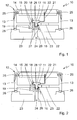
- the Fig. 1 shows a side sectional view of a vehicle control device 10 with a vehicle sensor 11.
- the vehicle control device 10 is a brake control device.
- the vehicle sensor 11 is designed as a pressure sensor.
- a pneumatic brake system is, in particular, an air pressure sensor for compressed air.
- the vehicle control device 10 has a housing 12.
- the housing 12 is designed as a so-called electronics housing. It has a lower housing part 13 and a housing cover 14. In order to protect the electronics from moisture, they typically form an interior that is at least splash-proof against the environment.
- a circuit board 15 In this interior space, the interior of the housing 12, a circuit board 15 is arranged.
- the electronic components of the electronic circuit of the vehicle control device 10 are arranged on the circuit board 15.
- the sensor 11 is arranged partly inside the housing 12 and partly outside.
- the vehicle sensor 11 is inserted into the lower base plate of the lower housing part 13.
- a recess 16 is provided in the lower housing part 13.
- the recess 16 corresponds to the external dimensions of the inserted vehicle sensor 11.
- the vehicle sensor 11 is inserted into this recess from the inside of the housing 12.
- the vehicle sensor 11 is only shown schematically here.
- the actual sensor system of the sensor 11 is arranged in the interior of this sensor housing 17, but was not shown here for the sake of clarity.
- the dimensions of the sensor housing 17 correspond in a lower inserted area to the dimensions of the recess 16. In an upper area, the housing 17 has a widened point which prevents the sensor housing 17 from slipping through the recess 16.
- a latching connection is provided.
- at least one latching hook 18 is provided on a spring element 19 on the lower housing part 13.
- both the spring element 19 and the at least one latching hook 18 are made in one piece from the material of the lower housing part 13.
- the lower housing part 13 is typically a molded part produced in one piece, for example an injection-molded part.
- a plurality of latching hooks 18 can also be provided.
- a recess 20 is provided in the area of the lower housing part 13 in the area of movement of the latching hook 18. This recess 20 enables the locking hook 18 to move horizontally in the plane of the drawing.
- the latching hook 18 is set up in such a way that it springs out to the right in the plane of the drawing in order to encompass the sensor housing 17 above and to rest against it laterally with spring force. This prevents the vehicle sensor 11 from being able to be moved upward in the plane of the drawing against the latching hook 18 out of the recess 16. In order to enable the vehicle sensor 11 to be removed, the latching hook 18 must accordingly first be moved to the left in the plane of the drawing against the spring force of the spring element 19 from the engagement of the sensor housing 17.
- the vehicle sensor 11 is also electrically connected to the printed circuit board 15 by means of an electrical connection, such as, for example, a lead frame 21 shown here or also a cable or other electrical conductors.
- an electrical connection such as, for example, a lead frame 21 shown here or also a cable or other electrical conductors.
- the conductive connection between the lead frame 21 and the printed circuit board 15 is established by means of press-fit contacts 22.
- the press-fit contacts 22 are in corresponding openings in the circuit board 15 introduced for contacting. They hold there by their own spring action.
- press-fit contacts 22 Due to the use of the press-fit contacts 22, it is only necessary during the manufacturing or assembly process to hold the printed circuit board 15 in a precise position. As soon as the electrical connection is established, the press-fit contacts 22 secure it permanently. If necessary, in embodiments that do not correspond to the invention, instead of press-fit contacts 22, other, possibly less advantageous types of connection can also be provided, such as soldered connections or the like.
- a recess 22 is formed in the area of the lower housing part 13. Through this recess 22, the connection between the printed circuit board 15 and the electrical conductors provided can be closed during assembly. In particular, the press-fit operation of the press-fit contacts 22 into the printed circuit board 15 can be carried out in a simple manner through the recess 22. At the same time, the base 23 forms a connection piece 29 for the passage of the pressure medium, such as, in particular, compressed air.
- the pressure medium such as, in particular, compressed air.
- the housing 12 is connected to a base 23 of the device of the vehicle to be controlled. This forms the lower end of the housing 12.
- the base 23 is typically also used to attach the vehicle control device 10 to the associated vehicle.
- the base 23 has a connector 29 for the passage of the pressure medium from the pneumatic system to the sensor 11 in order to be able to measure the pressure with the sensor 11.
- the housing 12 with the lower housing part 13 and the vehicle sensor 11 arranged there is inserted into the socket 29 during assembly. In this way the pressure connection is established and a seal is achieved at the same time.
- a hose (not shown here) can also pass through the base 23 to the vehicle sensor 11 be.
- This hose can be designed as a pressure hose, for example, and can lead a corresponding pressure medium to be measured, such as compressed air, to the vehicle sensor 11.
- the components of the housing 12 and the base 23 are sealed against one another by means of a plurality of seals 25, 26, 27.
- the seals 25 are provided for sealing the housing cover 14 with respect to the housing lower part 13.
- the electronics that is to say in this case the printed circuit board 15 and the upper part of the sensor 11, are arranged in the interior of this upper housing part in the drawing, which is closed off from the surroundings.
- Two further seals 27 are provided to seal the lower housing part 13 against the base 23 or the connection piece 29 of the device of the vehicle to be controlled.
- the recess 24 for the passage of the pressure medium is thus also sealed off from the interior of the housing.
- At least one seal 28 is also provided to seal off vehicle sensor 11 from the environment. This can be designed, for example, as an O-ring seal or similar. It ensures that the recess 24 is sealed off from the interior of the upper housing part containing the electronic components between the housing cover 14 and the lower housing part 13.
- the second embodiment of the Fig. 2 shows a somewhat modified design of the base 23.
- the base 23 is here sealed with the seal 28 directly with respect to the vehicle sensor 11.
- the outer space of the housing 12 is thus separated from the inner space thereof.
- a multiple seal, as in the first embodiment, is not necessary here. Seals are thus saved compared to the first exemplary embodiment.
- the sensor 11 is already sealed with respect to the lower housing part 13. This takes place here only after it has been placed on the base 23. Both variants have different advantages in production or in actual use. Depending on the intended use, one of the two exemplary embodiments shown or other variants according to the invention can also be used.
Claims (7)
- Calculateur de véhicule avec un circuit électronique, avec une carte de circuits imprimés (15), un boîtier (12) et au moins un capteur de véhicule (11), dans lequel les composants électroniques du circuit électronique du calculateur de véhicule (10) sont disposés sur la carte de circuits imprimés (15), dans lequel l'au moins un capteur de véhicule (11) est réalisé sous la forme d'un capteur de pression et dans lequel l'au moins un capteur de véhicule (11) est relié électriquement au circuit électronique pour l'enregistrement de valeurs de mesure, dans lequel le capteur de véhicule (11) est relié à la carte de circuits imprimés (15) au moyen d'une liaison électrique flexible, dans lequel la liaison électrique flexible est reliée à la carte de circuits imprimés (15) par l'intermédiaire d'un contact inséré à force (22), dans lequel une liaison par encliquetage et/ou un raccord à baïonnette est réalisé(e) entre le capteur de véhicule (11) ou le boîtier de capteur (17) et le boîtier (12) du calculateur de véhicule,
dans lequel le capteur de véhicule (11) est en partie à l'intérieur du boîtier (12) et en partie à l'extérieur, dans lequel un évidement (16) est prévu dans la partie inférieure de boîtier (13), qui correspond aux dimensions extérieures du capteur de véhicule (11) introduit et dans lequel le capteur de véhicule (11) est introduit à partir de l'intérieur du boîtier (12). - Calculateur de véhicule selon la revendication 1, caractérisé en ce que le capteur de véhicule (11) présente un boîtier de capteur (17), qui est relié mécaniquement exclusivement au boîtier (12).
- Calculateur de véhicule selon la revendication 1, caractérisé en ce que la liaison par encliquetage est formée par au moins un crochet d'encliquetage pour la réception et la fixation du capteur de véhicule.
- Calculateur de véhicule selon l'une quelconque des revendications précédentes, caractérisé en ce que le capteur de véhicule (11) est relié par une ligne électrique flexible au circuit électrique ou à la carte de circuits imprimés (15) de celui-ci, de préférence au moyen d'au moins une grille de connexion (21), d'un câble, d'un tracé conducteur, d'un contact élastique ou similaire.
- Calculateur de véhicule selon l'une quelconque des revendications précédentes, caractérisé en ce que le boîtier (12) présente un élément de retenue et/ou logement (16) pour le capteur de véhicule (11), dans lequel l'élément de retenue ou le logement (16) est prévu de préférence dans la zone d'une paroi du boîtier (12) et/ou dans lequel le capteur de véhicule (11) et/ou le boîtier de capteur (17) est réalisé en particulier par complémentarité de formes pour la retenue ou le logement.
- Calculateur de véhicule selon l'une quelconque des revendications précédentes, caractérisé en ce qu'une liaison pneumatique rigide du capteur de véhicule (11) à la source de valeurs de mesure est prévue, de préférence une tubulure en particulier tubulaire, dans lequel la liaison entre le capteur de véhicule (11) ou le boîtier de capteur (17) et le boîtier est de préférence enfichable.
- Calculateur de véhicule selon l'une quelconque des revendications précédentes, caractérisé en ce que le capteur de véhicule (11) est relié à la source de valeurs de mesure au moyen d'une liaison pneumatique flexible, en particulier liaison tubulaire, et/ou au moyen d'une liaison rigide, de préférence d'une tubulure rigide (29).
Applications Claiming Priority (2)
| Application Number | Priority Date | Filing Date | Title |
|---|---|---|---|
| DE102015012740.3A DE102015012740A1 (de) | 2015-10-01 | 2015-10-01 | Fahrzeugsteuergerät |
| PCT/EP2016/001487 WO2017054902A1 (fr) | 2015-10-01 | 2016-09-02 | Calculateur de véhicule |
Publications (2)
| Publication Number | Publication Date |
|---|---|
| EP3357309A1 EP3357309A1 (fr) | 2018-08-08 |
| EP3357309B1 true EP3357309B1 (fr) | 2021-08-18 |
Family
ID=56893921
Family Applications (1)
| Application Number | Title | Priority Date | Filing Date |
|---|---|---|---|
| EP16763196.9A Active EP3357309B1 (fr) | 2015-10-01 | 2016-09-02 | Calculateur de véhicule |
Country Status (5)
| Country | Link |
|---|---|
| US (1) | US10724916B2 (fr) |
| EP (1) | EP3357309B1 (fr) |
| CN (1) | CN107926127B (fr) |
| DE (1) | DE102015012740A1 (fr) |
| WO (1) | WO2017054902A1 (fr) |
Families Citing this family (3)
| Publication number | Priority date | Publication date | Assignee | Title |
|---|---|---|---|---|
| DE102017130656B3 (de) * | 2017-12-20 | 2018-12-13 | Mecomo Ag | Modulares befestigungssystem |
| US11454548B2 (en) * | 2020-11-30 | 2022-09-27 | Haier Us Appliance Solutions, Inc. | Sensor assembly for a recreational vehicle |
| US11839043B2 (en) * | 2021-04-29 | 2023-12-05 | Robert Bosch Llc | Electronic device with sealed housing |
Citations (1)
| Publication number | Priority date | Publication date | Assignee | Title |
|---|---|---|---|---|
| DE10122330A1 (de) * | 2000-05-11 | 2002-02-14 | Continental Teves Ag & Co Ohg | Bremsvorrichtung mit integriertem Drucksensormodul |
Family Cites Families (16)
| Publication number | Priority date | Publication date | Assignee | Title |
|---|---|---|---|---|
| US4640561A (en) * | 1985-11-15 | 1987-02-03 | Ford Motor Company | Flexible printed circuit connector |
| US5880372A (en) * | 1997-01-10 | 1999-03-09 | Integrated Sensor Solutions | Media compatible pressure sensor device utilizing self-aligned components which fit together without the need for adhesives |
| JP2002520211A (ja) * | 1998-07-08 | 2002-07-09 | コンティネンタル・テーベス・アクチエンゲゼルシヤフト・ウント・コンパニー・オッフェネ・ハンデルスゲゼルシヤフト | ブレーキ圧力制御装置 |
| DE10037842A1 (de) | 2000-02-23 | 2001-08-30 | Continental Teves Ag & Co Ohg | Drucksteuergerät |
| DE10022124B4 (de) | 2000-05-06 | 2010-01-14 | Wabco Gmbh | Elektronisches Steuergerät |
| DE10042734C1 (de) * | 2000-08-31 | 2002-03-14 | Wabco Gmbh & Co Ohg | Drucksensor |
| DE10107813A1 (de) * | 2001-02-20 | 2002-09-05 | Bosch Gmbh Robert | Drucksensormodul |
| DE10133066B4 (de) * | 2001-07-07 | 2008-06-19 | Endress + Hauser Gmbh + Co. Kg | Druckmeßgerät |
| DE202004020236U1 (de) | 2004-12-31 | 2006-05-04 | Intelligente Sensorsysteme Dresden Gmbh | Druck- und Temperatursensor |
| US7000478B1 (en) * | 2005-01-31 | 2006-02-21 | Texas Instruments Incorporated | Combined pressure and temperature transducer |
| JP5490349B2 (ja) * | 2006-05-24 | 2014-05-14 | 株式会社デンソー | 圧力センサ |
| DE102007029913A1 (de) | 2007-06-28 | 2009-01-02 | Robert Bosch Gmbh | Elektrisches Steuergerät |
| US20090140572A1 (en) * | 2007-12-04 | 2009-06-04 | Mando Corporation | Pressure sensor |
| JP5956948B2 (ja) | 2013-03-21 | 2016-07-27 | 日立オートモティブシステムズ株式会社 | 電子制御装置 |
| EP2808665B1 (fr) * | 2013-05-28 | 2019-02-20 | Sensata Technologies, Inc. | Bouchon de mesure |
| DE102013220091A1 (de) | 2013-10-02 | 2015-04-02 | Kavlico GmbH | Drucksensor |
-
2015
- 2015-10-01 DE DE102015012740.3A patent/DE102015012740A1/de not_active Withdrawn
-
2016
- 2016-09-02 CN CN201680046984.4A patent/CN107926127B/zh active Active
- 2016-09-02 US US15/764,718 patent/US10724916B2/en active Active
- 2016-09-02 EP EP16763196.9A patent/EP3357309B1/fr active Active
- 2016-09-02 WO PCT/EP2016/001487 patent/WO2017054902A1/fr active Application Filing
Patent Citations (1)
| Publication number | Priority date | Publication date | Assignee | Title |
|---|---|---|---|---|
| DE10122330A1 (de) * | 2000-05-11 | 2002-02-14 | Continental Teves Ag & Co Ohg | Bremsvorrichtung mit integriertem Drucksensormodul |
Also Published As
| Publication number | Publication date |
|---|---|
| EP3357309A1 (fr) | 2018-08-08 |
| US20180283975A1 (en) | 2018-10-04 |
| WO2017054902A1 (fr) | 2017-04-06 |
| CN107926127A (zh) | 2018-04-17 |
| US10724916B2 (en) | 2020-07-28 |
| CN107926127B (zh) | 2020-10-02 |
| DE102015012740A1 (de) | 2017-04-06 |
Similar Documents
| Publication | Publication Date | Title |
|---|---|---|
| EP2687823B2 (fr) | Dispositif destiné à l'enregistrement et au traitement de valeurs de mesure de capteur et/ou à la commande d'actionneurs | |
| EP3357309B1 (fr) | Calculateur de véhicule | |
| EP3312940B1 (fr) | Insert de contacts pour une partie de connecteur | |
| DE102007020882B4 (de) | Einrichtung zur Überprüfung der Befestigung einer Leiterbahnplatte an einem Träger | |
| DE202007018307U1 (de) | Messeinrichtung für Steckverbinder | |
| DE102018215656A1 (de) | Druckmessvorrichtung für airbag | |
| EP1728414B1 (fr) | Dispositif comprenant un moteur electrique et une carte de circuits imprimes principale et procede de montage | |
| DE102015204058A1 (de) | Verbinder für elektronisches Gerät | |
| DE202017100608U1 (de) | Steckverbinder | |
| DE102012102842B4 (de) | Befestigung und Abdichtung von Steckanschlussmodulen in einer Gehäusewand | |
| EP3433897B1 (fr) | Couvercle de boîtier, capteur de batterie et procédé de fabrication d'un capteur de batterie | |
| DE102011101767A1 (de) | Verbinder zur Herstellung einer elektrischen Kontaktverbindung | |
| DE102013214124B4 (de) | Fahrzeugmontierte Kameravorrichtung | |
| WO2005064282A1 (fr) | Appareil de mesure modulaire | |
| DE102012025518B4 (de) | Drucksensorelement | |
| DE102015204969A1 (de) | Befestigungsaufbau für einen Stromsensor und ein elektrisch leitendes Glied | |
| DE202010011496U1 (de) | Anschlussdose mit Prüfkontakt | |
| EP2217811B1 (fr) | Systeme d'installation electrique de type modulaire | |
| DE102014102555B4 (de) | Elektrische Einrichtung mit Pendelkontakt | |
| EP2856515B1 (fr) | Boîte de raccordement et de connexion électrique pour module à cellules solaires | |
| AT517608B1 (de) | Elektronikeinheit für ein Durchflussmessgerät | |
| DE102015007725A1 (de) | Elektrischer Steckverbinder | |
| WO2023030771A1 (fr) | Dispositif de réception d'un affichage pour un appareil de terrain d'automatisation | |
| EP0584683B1 (fr) | Dispositif de fermeture d'une ouverture dans une paroi d'une boîte | |
| DE102021122566A1 (de) | Feldgerät der Automatisierungstechnik |
Legal Events
| Date | Code | Title | Description |
|---|---|---|---|
| STAA | Information on the status of an ep patent application or granted ep patent |
Free format text: STATUS: THE INTERNATIONAL PUBLICATION HAS BEEN MADE |
|
| PUAI | Public reference made under article 153(3) epc to a published international application that has entered the european phase |
Free format text: ORIGINAL CODE: 0009012 |
|
| STAA | Information on the status of an ep patent application or granted ep patent |
Free format text: STATUS: REQUEST FOR EXAMINATION WAS MADE |
|
| 17P | Request for examination filed |
Effective date: 20180502 |
|
| AK | Designated contracting states |
Kind code of ref document: A1 Designated state(s): AL AT BE BG CH CY CZ DE DK EE ES FI FR GB GR HR HU IE IS IT LI LT LU LV MC MK MT NL NO PL PT RO RS SE SI SK SM TR |
|
| AX | Request for extension of the european patent |
Extension state: BA ME |
|
| DAV | Request for validation of the european patent (deleted) | ||
| DAX | Request for extension of the european patent (deleted) | ||
| STAA | Information on the status of an ep patent application or granted ep patent |
Free format text: STATUS: EXAMINATION IS IN PROGRESS |
|
| 17Q | First examination report despatched |
Effective date: 20200324 |
|
| STAA | Information on the status of an ep patent application or granted ep patent |
Free format text: STATUS: EXAMINATION IS IN PROGRESS |
|
| RAP3 | Party data changed (applicant data changed or rights of an application transferred) |
Owner name: ZF CV SYSTEMS HANNOVER GMBH |
|
| GRAP | Despatch of communication of intention to grant a patent |
Free format text: ORIGINAL CODE: EPIDOSNIGR1 |
|
| STAA | Information on the status of an ep patent application or granted ep patent |
Free format text: STATUS: GRANT OF PATENT IS INTENDED |
|
| INTG | Intention to grant announced |
Effective date: 20210528 |
|
| GRAS | Grant fee paid |
Free format text: ORIGINAL CODE: EPIDOSNIGR3 |
|
| GRAA | (expected) grant |
Free format text: ORIGINAL CODE: 0009210 |
|
| STAA | Information on the status of an ep patent application or granted ep patent |
Free format text: STATUS: THE PATENT HAS BEEN GRANTED |
|
| AK | Designated contracting states |
Kind code of ref document: B1 Designated state(s): AL AT BE BG CH CY CZ DE DK EE ES FI FR GB GR HR HU IE IS IT LI LT LU LV MC MK MT NL NO PL PT RO RS SE SI SK SM TR |
|
| REG | Reference to a national code |
Ref country code: GB Ref legal event code: FG4D Free format text: NOT ENGLISH |
|
| REG | Reference to a national code |
Ref country code: CH Ref legal event code: EP |
|
| REG | Reference to a national code |
Ref country code: DE Ref legal event code: R096 Ref document number: 502016013659 Country of ref document: DE |
|
| REG | Reference to a national code |
Ref country code: IE Ref legal event code: FG4D Free format text: LANGUAGE OF EP DOCUMENT: GERMAN Ref country code: AT Ref legal event code: REF Ref document number: 1422824 Country of ref document: AT Kind code of ref document: T Effective date: 20210915 |
|
| REG | Reference to a national code |
Ref country code: LT Ref legal event code: MG9D |
|
| REG | Reference to a national code |
Ref country code: NL Ref legal event code: MP Effective date: 20210818 |
|
| PG25 | Lapsed in a contracting state [announced via postgrant information from national office to epo] |
Ref country code: RS Free format text: LAPSE BECAUSE OF FAILURE TO SUBMIT A TRANSLATION OF THE DESCRIPTION OR TO PAY THE FEE WITHIN THE PRESCRIBED TIME-LIMIT Effective date: 20210818 Ref country code: SE Free format text: LAPSE BECAUSE OF FAILURE TO SUBMIT A TRANSLATION OF THE DESCRIPTION OR TO PAY THE FEE WITHIN THE PRESCRIBED TIME-LIMIT Effective date: 20210818 Ref country code: FI Free format text: LAPSE BECAUSE OF FAILURE TO SUBMIT A TRANSLATION OF THE DESCRIPTION OR TO PAY THE FEE WITHIN THE PRESCRIBED TIME-LIMIT Effective date: 20210818 Ref country code: ES Free format text: LAPSE BECAUSE OF FAILURE TO SUBMIT A TRANSLATION OF THE DESCRIPTION OR TO PAY THE FEE WITHIN THE PRESCRIBED TIME-LIMIT Effective date: 20210818 Ref country code: HR Free format text: LAPSE BECAUSE OF FAILURE TO SUBMIT A TRANSLATION OF THE DESCRIPTION OR TO PAY THE FEE WITHIN THE PRESCRIBED TIME-LIMIT Effective date: 20210818 Ref country code: NO Free format text: LAPSE BECAUSE OF FAILURE TO SUBMIT A TRANSLATION OF THE DESCRIPTION OR TO PAY THE FEE WITHIN THE PRESCRIBED TIME-LIMIT Effective date: 20211118 Ref country code: PT Free format text: LAPSE BECAUSE OF FAILURE TO SUBMIT A TRANSLATION OF THE DESCRIPTION OR TO PAY THE FEE WITHIN THE PRESCRIBED TIME-LIMIT Effective date: 20211220 Ref country code: BG Free format text: LAPSE BECAUSE OF FAILURE TO SUBMIT A TRANSLATION OF THE DESCRIPTION OR TO PAY THE FEE WITHIN THE PRESCRIBED TIME-LIMIT Effective date: 20211118 Ref country code: LT Free format text: LAPSE BECAUSE OF FAILURE TO SUBMIT A TRANSLATION OF THE DESCRIPTION OR TO PAY THE FEE WITHIN THE PRESCRIBED TIME-LIMIT Effective date: 20210818 |
|
| PG25 | Lapsed in a contracting state [announced via postgrant information from national office to epo] |
Ref country code: PL Free format text: LAPSE BECAUSE OF FAILURE TO SUBMIT A TRANSLATION OF THE DESCRIPTION OR TO PAY THE FEE WITHIN THE PRESCRIBED TIME-LIMIT Effective date: 20210818 Ref country code: LV Free format text: LAPSE BECAUSE OF FAILURE TO SUBMIT A TRANSLATION OF THE DESCRIPTION OR TO PAY THE FEE WITHIN THE PRESCRIBED TIME-LIMIT Effective date: 20210818 Ref country code: GR Free format text: LAPSE BECAUSE OF FAILURE TO SUBMIT A TRANSLATION OF THE DESCRIPTION OR TO PAY THE FEE WITHIN THE PRESCRIBED TIME-LIMIT Effective date: 20211119 |
|
| REG | Reference to a national code |
Ref country code: DE Ref legal event code: R081 Ref document number: 502016013659 Country of ref document: DE Owner name: ZF CV SYSTEMS EUROPE BV, BE Free format text: FORMER OWNER: ZF CV SYSTEMS HANNOVER GMBH, 30453 HANNOVER, DE |
|
| PG25 | Lapsed in a contracting state [announced via postgrant information from national office to epo] |
Ref country code: NL Free format text: LAPSE BECAUSE OF FAILURE TO SUBMIT A TRANSLATION OF THE DESCRIPTION OR TO PAY THE FEE WITHIN THE PRESCRIBED TIME-LIMIT Effective date: 20210818 |
|
| PG25 | Lapsed in a contracting state [announced via postgrant information from national office to epo] |
Ref country code: DK Free format text: LAPSE BECAUSE OF FAILURE TO SUBMIT A TRANSLATION OF THE DESCRIPTION OR TO PAY THE FEE WITHIN THE PRESCRIBED TIME-LIMIT Effective date: 20210818 |
|
| REG | Reference to a national code |
Ref country code: CH Ref legal event code: PL |
|
| REG | Reference to a national code |
Ref country code: DE Ref legal event code: R097 Ref document number: 502016013659 Country of ref document: DE |
|
| REG | Reference to a national code |
Ref country code: BE Ref legal event code: MM Effective date: 20210930 |
|
| PG25 | Lapsed in a contracting state [announced via postgrant information from national office to epo] |
Ref country code: SM Free format text: LAPSE BECAUSE OF FAILURE TO SUBMIT A TRANSLATION OF THE DESCRIPTION OR TO PAY THE FEE WITHIN THE PRESCRIBED TIME-LIMIT Effective date: 20210818 Ref country code: SK Free format text: LAPSE BECAUSE OF FAILURE TO SUBMIT A TRANSLATION OF THE DESCRIPTION OR TO PAY THE FEE WITHIN THE PRESCRIBED TIME-LIMIT Effective date: 20210818 Ref country code: RO Free format text: LAPSE BECAUSE OF FAILURE TO SUBMIT A TRANSLATION OF THE DESCRIPTION OR TO PAY THE FEE WITHIN THE PRESCRIBED TIME-LIMIT Effective date: 20210818 Ref country code: MC Free format text: LAPSE BECAUSE OF FAILURE TO SUBMIT A TRANSLATION OF THE DESCRIPTION OR TO PAY THE FEE WITHIN THE PRESCRIBED TIME-LIMIT Effective date: 20210818 Ref country code: EE Free format text: LAPSE BECAUSE OF FAILURE TO SUBMIT A TRANSLATION OF THE DESCRIPTION OR TO PAY THE FEE WITHIN THE PRESCRIBED TIME-LIMIT Effective date: 20210818 Ref country code: CZ Free format text: LAPSE BECAUSE OF FAILURE TO SUBMIT A TRANSLATION OF THE DESCRIPTION OR TO PAY THE FEE WITHIN THE PRESCRIBED TIME-LIMIT Effective date: 20210818 Ref country code: AL Free format text: LAPSE BECAUSE OF FAILURE TO SUBMIT A TRANSLATION OF THE DESCRIPTION OR TO PAY THE FEE WITHIN THE PRESCRIBED TIME-LIMIT Effective date: 20210818 |
|
| PLBE | No opposition filed within time limit |
Free format text: ORIGINAL CODE: 0009261 |
|
| STAA | Information on the status of an ep patent application or granted ep patent |
Free format text: STATUS: NO OPPOSITION FILED WITHIN TIME LIMIT |
|
| 26N | No opposition filed |
Effective date: 20220519 |
|
| PG25 | Lapsed in a contracting state [announced via postgrant information from national office to epo] |
Ref country code: LU Free format text: LAPSE BECAUSE OF NON-PAYMENT OF DUE FEES Effective date: 20210902 Ref country code: IT Free format text: LAPSE BECAUSE OF FAILURE TO SUBMIT A TRANSLATION OF THE DESCRIPTION OR TO PAY THE FEE WITHIN THE PRESCRIBED TIME-LIMIT Effective date: 20210818 Ref country code: IE Free format text: LAPSE BECAUSE OF NON-PAYMENT OF DUE FEES Effective date: 20210902 Ref country code: BE Free format text: LAPSE BECAUSE OF NON-PAYMENT OF DUE FEES Effective date: 20210930 |
|
| PG25 | Lapsed in a contracting state [announced via postgrant information from national office to epo] |
Ref country code: SI Free format text: LAPSE BECAUSE OF FAILURE TO SUBMIT A TRANSLATION OF THE DESCRIPTION OR TO PAY THE FEE WITHIN THE PRESCRIBED TIME-LIMIT Effective date: 20210818 Ref country code: LI Free format text: LAPSE BECAUSE OF NON-PAYMENT OF DUE FEES Effective date: 20210930 Ref country code: CH Free format text: LAPSE BECAUSE OF NON-PAYMENT OF DUE FEES Effective date: 20210930 |
|
| REG | Reference to a national code |
Ref country code: AT Ref legal event code: MM01 Ref document number: 1422824 Country of ref document: AT Kind code of ref document: T Effective date: 20210902 |
|
| PG25 | Lapsed in a contracting state [announced via postgrant information from national office to epo] |
Ref country code: AT Free format text: LAPSE BECAUSE OF NON-PAYMENT OF DUE FEES Effective date: 20210902 |
|
| PG25 | Lapsed in a contracting state [announced via postgrant information from national office to epo] |
Ref country code: CY Free format text: LAPSE BECAUSE OF FAILURE TO SUBMIT A TRANSLATION OF THE DESCRIPTION OR TO PAY THE FEE WITHIN THE PRESCRIBED TIME-LIMIT Effective date: 20210818 |
|
| P01 | Opt-out of the competence of the unified patent court (upc) registered |
Effective date: 20230528 |
|
| PG25 | Lapsed in a contracting state [announced via postgrant information from national office to epo] |
Ref country code: HU Free format text: LAPSE BECAUSE OF FAILURE TO SUBMIT A TRANSLATION OF THE DESCRIPTION OR TO PAY THE FEE WITHIN THE PRESCRIBED TIME-LIMIT; INVALID AB INITIO Effective date: 20160902 |
|
| PGFP | Annual fee paid to national office [announced via postgrant information from national office to epo] |
Ref country code: GB Payment date: 20230713 Year of fee payment: 8 |
|
| PGFP | Annual fee paid to national office [announced via postgrant information from national office to epo] |
Ref country code: FR Payment date: 20230703 Year of fee payment: 8 Ref country code: DE Payment date: 20230712 Year of fee payment: 8 |
|
| PG25 | Lapsed in a contracting state [announced via postgrant information from national office to epo] |
Ref country code: MK Free format text: LAPSE BECAUSE OF FAILURE TO SUBMIT A TRANSLATION OF THE DESCRIPTION OR TO PAY THE FEE WITHIN THE PRESCRIBED TIME-LIMIT Effective date: 20210818 |