EP3357309B1 - Vehicle control device - Google Patents
Vehicle control device Download PDFInfo
- Publication number
- EP3357309B1 EP3357309B1 EP16763196.9A EP16763196A EP3357309B1 EP 3357309 B1 EP3357309 B1 EP 3357309B1 EP 16763196 A EP16763196 A EP 16763196A EP 3357309 B1 EP3357309 B1 EP 3357309B1
- Authority
- EP
- European Patent Office
- Prior art keywords
- housing
- sensor
- vehicle
- vehicle sensor
- control device
- Prior art date
- Legal status (The legal status is an assumption and is not a legal conclusion. Google has not performed a legal analysis and makes no representation as to the accuracy of the status listed.)
- Active
Links
- 239000004020 conductor Substances 0.000 claims description 8
- 238000005259 measurement Methods 0.000 claims description 7
- 238000004519 manufacturing process Methods 0.000 description 3
- 230000005540 biological transmission Effects 0.000 description 2
- 230000007547 defect Effects 0.000 description 2
- 230000001419 dependent effect Effects 0.000 description 2
- 238000000034 method Methods 0.000 description 2
- 238000007789 sealing Methods 0.000 description 2
- 230000009471 action Effects 0.000 description 1
- 238000009530 blood pressure measurement Methods 0.000 description 1
- 238000004891 communication Methods 0.000 description 1
- 238000013461 design Methods 0.000 description 1
- 238000011156 evaluation Methods 0.000 description 1
- 239000012530 fluid Substances 0.000 description 1
- 238000010438 heat treatment Methods 0.000 description 1
- 238000009434 installation Methods 0.000 description 1
- 230000007774 longterm Effects 0.000 description 1
- 239000000463 material Substances 0.000 description 1
- 239000012528 membrane Substances 0.000 description 1
- 230000008569 process Effects 0.000 description 1
- 230000009467 reduction Effects 0.000 description 1
- 230000001105 regulatory effect Effects 0.000 description 1
Images
Classifications
-
- G—PHYSICS
- G01—MEASURING; TESTING
- G01L—MEASURING FORCE, STRESS, TORQUE, WORK, MECHANICAL POWER, MECHANICAL EFFICIENCY, OR FLUID PRESSURE
- G01L19/00—Details of, or accessories for, apparatus for measuring steady or quasi-steady pressure of a fluent medium insofar as such details or accessories are not special to particular types of pressure gauges
- G01L19/14—Housings
- G01L19/148—Details about the circuit board integration, e.g. integrated with the diaphragm surface or encapsulation
-
- H—ELECTRICITY
- H05—ELECTRIC TECHNIQUES NOT OTHERWISE PROVIDED FOR
- H05K—PRINTED CIRCUITS; CASINGS OR CONSTRUCTIONAL DETAILS OF ELECTRIC APPARATUS; MANUFACTURE OF ASSEMBLAGES OF ELECTRICAL COMPONENTS
- H05K5/00—Casings, cabinets or drawers for electric apparatus
- H05K5/0026—Casings, cabinets or drawers for electric apparatus provided with connectors and printed circuit boards [PCB], e.g. automotive electronic control units
- H05K5/0043—Casings, cabinets or drawers for electric apparatus provided with connectors and printed circuit boards [PCB], e.g. automotive electronic control units comprising a frame housing mating with two lids wherein the PCB is flat mounted on the frame housing
-
- G—PHYSICS
- G01—MEASURING; TESTING
- G01L—MEASURING FORCE, STRESS, TORQUE, WORK, MECHANICAL POWER, MECHANICAL EFFICIENCY, OR FLUID PRESSURE
- G01L19/00—Details of, or accessories for, apparatus for measuring steady or quasi-steady pressure of a fluent medium insofar as such details or accessories are not special to particular types of pressure gauges
- G01L19/0061—Electrical connection means
- G01L19/0084—Electrical connection means to the outside of the housing
-
- G—PHYSICS
- G01—MEASURING; TESTING
- G01L—MEASURING FORCE, STRESS, TORQUE, WORK, MECHANICAL POWER, MECHANICAL EFFICIENCY, OR FLUID PRESSURE
- G01L19/00—Details of, or accessories for, apparatus for measuring steady or quasi-steady pressure of a fluent medium insofar as such details or accessories are not special to particular types of pressure gauges
- G01L19/14—Housings
- G01L19/147—Details about the mounting of the sensor to support or covering means
-
- H—ELECTRICITY
- H05—ELECTRIC TECHNIQUES NOT OTHERWISE PROVIDED FOR
- H05K—PRINTED CIRCUITS; CASINGS OR CONSTRUCTIONAL DETAILS OF ELECTRIC APPARATUS; MANUFACTURE OF ASSEMBLAGES OF ELECTRICAL COMPONENTS
- H05K5/00—Casings, cabinets or drawers for electric apparatus
- H05K5/0017—Casings, cabinets or drawers for electric apparatus with operator interface units
-
- H—ELECTRICITY
- H05—ELECTRIC TECHNIQUES NOT OTHERWISE PROVIDED FOR
- H05K—PRINTED CIRCUITS; CASINGS OR CONSTRUCTIONAL DETAILS OF ELECTRIC APPARATUS; MANUFACTURE OF ASSEMBLAGES OF ELECTRICAL COMPONENTS
- H05K5/00—Casings, cabinets or drawers for electric apparatus
- H05K5/02—Details
- H05K5/0204—Mounting supporting structures on the outside of casings
-
- H—ELECTRICITY
- H05—ELECTRIC TECHNIQUES NOT OTHERWISE PROVIDED FOR
- H05K—PRINTED CIRCUITS; CASINGS OR CONSTRUCTIONAL DETAILS OF ELECTRIC APPARATUS; MANUFACTURE OF ASSEMBLAGES OF ELECTRICAL COMPONENTS
- H05K5/00—Casings, cabinets or drawers for electric apparatus
- H05K5/02—Details
- H05K5/0247—Electrical details of casings, e.g. terminals, passages for cables or wiring
-
- B—PERFORMING OPERATIONS; TRANSPORTING
- B60—VEHICLES IN GENERAL
- B60Y—INDEXING SCHEME RELATING TO ASPECTS CROSS-CUTTING VEHICLE TECHNOLOGY
- B60Y2400/00—Special features of vehicle units
- B60Y2400/30—Sensors
- B60Y2400/306—Pressure sensors
-
- B—PERFORMING OPERATIONS; TRANSPORTING
- B60—VEHICLES IN GENERAL
- B60Y—INDEXING SCHEME RELATING TO ASPECTS CROSS-CUTTING VEHICLE TECHNOLOGY
- B60Y2410/00—Constructional features of vehicle sub-units
- B60Y2410/115—Electric wiring; Electric connectors
-
- H—ELECTRICITY
- H05—ELECTRIC TECHNIQUES NOT OTHERWISE PROVIDED FOR
- H05K—PRINTED CIRCUITS; CASINGS OR CONSTRUCTIONAL DETAILS OF ELECTRIC APPARATUS; MANUFACTURE OF ASSEMBLAGES OF ELECTRICAL COMPONENTS
- H05K5/00—Casings, cabinets or drawers for electric apparatus
- H05K5/02—Details
- H05K5/03—Covers
-
- H—ELECTRICITY
- H05—ELECTRIC TECHNIQUES NOT OTHERWISE PROVIDED FOR
- H05K—PRINTED CIRCUITS; CASINGS OR CONSTRUCTIONAL DETAILS OF ELECTRIC APPARATUS; MANUFACTURE OF ASSEMBLAGES OF ELECTRICAL COMPONENTS
- H05K5/00—Casings, cabinets or drawers for electric apparatus
- H05K5/06—Hermetically-sealed casings
- H05K5/061—Hermetically-sealed casings sealed by a gasket held between a removable cover and a body, e.g. O-ring, packing
Definitions
- the invention relates to a vehicle control device according to the preamble of claim 1.
- Vehicle control units are used to monitor and control a large number of functions of a vehicle. These work partly autonomously and partly dependent on driver intervention.
- the individual vehicle control units are usually specialized in one or a few functions, such as the braking system. This means that there are typically a number of different vehicle control units in a vehicle.
- the invention described here is basically suitable for different types of vehicle control devices, but is described here as an example for brake control devices.
- a vehicle control device is equipped or connected with suitable vehicle sensors.
- the vehicle sensors are electrically connected to the vehicle control device or to an electronic circuit or printed circuit board arranged in the interior of a housing of the vehicle control device.
- the at least one vehicle sensor is preferably designed as a pressure sensor.
- it is a pressure sensor of a pneumatic system, for example a pneumatic brake system.
- the vehicle sensors are designed as separate units and only have an electrical cable connection to the vehicle control unit or its electronic circuit connected.
- the disadvantage here is that the sensor has to have a separate housing along with a corresponding fastening and, above all, that an electrical cable connection suffers in its reliability in the long term due to vibrations and the like. Cabling is also complex, especially when there are several sensors.
- the vehicle sensor is arranged directly on the electronic circuit or the electronic circuit board, so that there is a permanent electrical connection.
- the corresponding measured value for example an air pressure or the like, or the measurement object, such as a pressure medium, must then be transported to the vehicle sensor, for example by means of lines, deflectors, hoses or the like.
- suitable bushings and connections for, for example, a pressure hose or the like must be provided.
- This solution is complex, especially when arranging several sensors.
- DE 10 2013 220 091 A1 discloses a pressure sensor for measuring the pressure of a fluid, in particular a brake pressure sensor, with a pressure transducer which comprises a pressure port having a pressure channel and a measuring membrane which has pressure-intensive elements on the side facing away from the pressure channel, and a circuit board with evaluation electronics arranged thereon.
- the pressure sensor is characterized by a circuit board carrier which has several electrical conductors which electrically connect the pressure-sensitive elements to the circuit board, the electrical conductors being electrically connected to the circuit board by being press-fitted.
- DE 100 37 842 A1 discloses a pressure control device for wheel slip-regulated hydraulic motor vehicle brake systems, which is particularly suitable for automatic braking intervention, with a first housing for receiving a plurality of pressure medium channels which are in communication with a plurality of pressure control valves and pressure sensors in the first housing, with a second housing arranged on the first housing for receiving electrical and / or electronic components connected to the pressure control valves. At least one of the pressure sensor elements is combined with a heating element to form an assembly that can be handled independently.
- EP 1 152 231 A2 discloses an electronic control device with a housing and a cover which contains a printed circuit board which is equipped with components and with at least one pressure sensor.
- a snorkel is used to supply pressure to the pressure sensor, the lower part of which surrounds the pressure sensor and the edge of which is sealed against the circuit board.
- the control device can be used in particular in so-called mechatronics in which both electrical and mechanical signals are processed.
- a pressure and temperature sensor with a housing with supply of the pressure medium, a pressure measuring cell, a printed circuit board and a connection part with electrical contacts, with an annular plastic part sitting on the measuring cell, which includes the head of the measuring cell, on one side a holding part for the lead frame and the rest of the interior of the plastic part is covered with a circuit board and an ASIC is arranged on the circuit board.
- DE 101 22 330 A1 discloses a braking device with an integrated pressure sensor module.
- the object on which the invention is based is therefore to provide a vehicle control device with a vehicle sensor which eliminates the disadvantages mentioned above.
- reliable and durable mechanical and electrical connections between the vehicle control unit and the vehicle sensor are to be created.
- the above-mentioned object is achieved by a vehicle control device with the features of claim 1. Accordingly, the vehicle sensor is connected to the housing of the vehicle control unit.
- the housing has a high mechanical stability and can therefore be used for a reliable connection to the vehicle sensor. In particular, a load on the printed circuit board of the electronic circuit is reduced.
- the vehicle sensor preferably has a sensor housing which is connected to the housing of the vehicle control device.
- a secure fastening is achieved by connecting the two housings to one another.
- the vehicle sensor or the sensor housing is mechanically connected to the housing.
- the mechanical connection provides a secure hold.
- the fastening is particularly preferably carried out exclusively with the housing. The latter ensures that there is no mechanical stress, for example electronic components or the like.
- a latching connection and / or a bayonet connection is formed between the vehicle sensor or the sensor housing on the one hand and the housing on the other hand. This enables easy, preferably tool-free assembly to be achieved.
- the latching connection is preferably formed by at least one latching hook. This is used in particular to hold and fix the vehicle sensor. This enables the vehicle sensor to be fastened to the housing in a detachable and, at the same time, durable manner.
- the vehicle sensor is connected to the electronic circuit by a flexible electrical connection.
- a cable, at least one conductor track, at least one spring contact or the like can be considered as the flexible electrical connection.
- At least one press-fit contact is provided, preferably in combination with a cable and / or a conductor track. This largely avoids the transmission of mechanical movements from the vehicle sensor to the electronic circuit or electronic circuit board.
- a detachable and / or flexible connection is formed between the vehicle sensor or the sensor housing and the housing.
- a detachable connection enables the vehicle sensor to be exchanged easily, for example in the event of a defect. Relative movements between the vehicle sensor and the housing of the vehicle control unit can be intercepted through a flexible connection. This particularly ensures a Reduction of the load on the housing parts.
- a flexible connection can be made, for example, by elastic components, such as a rubber seal or the like.
- a permanently non-detachable connection is preferably formed between the vehicle sensor and the sensor housing and the housing. This ensures that the vehicle sensor is permanently connected to the vehicle control unit. To ensure a high level of operational reliability, the vehicle control unit and vehicle sensor must then be completely replaced in the event of a component defect, so that only components that belong together can be re-installed as replacements.
- the housing has, in particular, a holder or receptacle for the vehicle sensor.
- the vehicle sensor can be used in this holder or receptacle, in particular with its housing.
- the holder or receptacle is preferably provided in the area of a wall of the housing.
- the vehicle sensor or the sensor housing is designed in a form-fitting manner for holding or receiving. This ensures that the vehicle sensor is securely and permanently attached to the vehicle control unit.
- the vehicle sensor can in particular be arranged inside the housing or inside the housing.
- the vehicle sensor is then preferably arranged in the area of a housing wall and / or on a housing wall. In this way, on the one hand, good electrical contact and, if necessary, sealing of the housing with respect to the environment is achieved. On the other hand, a breakthrough can enable the sensor to contact the outside in order to record measured values.
- the vehicle sensor can be arranged on the outside of the housing, preferably outside the housing.
- the arrangement is then preferably carried out in the area of a housing wall. This makes it easy to mount the vehicle sensor on the vehicle control unit enables. In addition, contact with a measurement data source can be ensured in a simple manner.
- the vehicle sensor is preferably connected to the measured value source by means of a rigid connection.
- a rigid connection In particular, it is a pneumatic connection.
- a connector, in particular a rigid connector, is particularly preferably provided for this purpose
- the vehicle sensor can in particular alternatively be connected to the measured value source by means of a flexible connection.
- a flexible connection In particular, it is a pneumatic connection.
- a hose in particular a pressure hose, is preferably provided.
- the measured value source must be connected to the vehicle sensor in order to record measurement data.
- a flexible connection ensures that relative movements, for example due to vibrations or the like, on the one hand, are not transmitted and, on the other hand, the mechanical stability is influenced as little as possible.
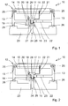
- the Fig. 1 shows a side sectional view of a vehicle control device 10 with a vehicle sensor 11.
- the vehicle control device 10 is a brake control device.
- the vehicle sensor 11 is designed as a pressure sensor.
- a pneumatic brake system is, in particular, an air pressure sensor for compressed air.
- the vehicle control device 10 has a housing 12.
- the housing 12 is designed as a so-called electronics housing. It has a lower housing part 13 and a housing cover 14. In order to protect the electronics from moisture, they typically form an interior that is at least splash-proof against the environment.
- a circuit board 15 In this interior space, the interior of the housing 12, a circuit board 15 is arranged.
- the electronic components of the electronic circuit of the vehicle control device 10 are arranged on the circuit board 15.
- the sensor 11 is arranged partly inside the housing 12 and partly outside.
- the vehicle sensor 11 is inserted into the lower base plate of the lower housing part 13.
- a recess 16 is provided in the lower housing part 13.
- the recess 16 corresponds to the external dimensions of the inserted vehicle sensor 11.
- the vehicle sensor 11 is inserted into this recess from the inside of the housing 12.
- the vehicle sensor 11 is only shown schematically here.
- the actual sensor system of the sensor 11 is arranged in the interior of this sensor housing 17, but was not shown here for the sake of clarity.
- the dimensions of the sensor housing 17 correspond in a lower inserted area to the dimensions of the recess 16. In an upper area, the housing 17 has a widened point which prevents the sensor housing 17 from slipping through the recess 16.
- a latching connection is provided.
- at least one latching hook 18 is provided on a spring element 19 on the lower housing part 13.
- both the spring element 19 and the at least one latching hook 18 are made in one piece from the material of the lower housing part 13.
- the lower housing part 13 is typically a molded part produced in one piece, for example an injection-molded part.
- a plurality of latching hooks 18 can also be provided.
- a recess 20 is provided in the area of the lower housing part 13 in the area of movement of the latching hook 18. This recess 20 enables the locking hook 18 to move horizontally in the plane of the drawing.
- the latching hook 18 is set up in such a way that it springs out to the right in the plane of the drawing in order to encompass the sensor housing 17 above and to rest against it laterally with spring force. This prevents the vehicle sensor 11 from being able to be moved upward in the plane of the drawing against the latching hook 18 out of the recess 16. In order to enable the vehicle sensor 11 to be removed, the latching hook 18 must accordingly first be moved to the left in the plane of the drawing against the spring force of the spring element 19 from the engagement of the sensor housing 17.
- the vehicle sensor 11 is also electrically connected to the printed circuit board 15 by means of an electrical connection, such as, for example, a lead frame 21 shown here or also a cable or other electrical conductors.
- an electrical connection such as, for example, a lead frame 21 shown here or also a cable or other electrical conductors.
- the conductive connection between the lead frame 21 and the printed circuit board 15 is established by means of press-fit contacts 22.
- the press-fit contacts 22 are in corresponding openings in the circuit board 15 introduced for contacting. They hold there by their own spring action.
- press-fit contacts 22 Due to the use of the press-fit contacts 22, it is only necessary during the manufacturing or assembly process to hold the printed circuit board 15 in a precise position. As soon as the electrical connection is established, the press-fit contacts 22 secure it permanently. If necessary, in embodiments that do not correspond to the invention, instead of press-fit contacts 22, other, possibly less advantageous types of connection can also be provided, such as soldered connections or the like.
- a recess 22 is formed in the area of the lower housing part 13. Through this recess 22, the connection between the printed circuit board 15 and the electrical conductors provided can be closed during assembly. In particular, the press-fit operation of the press-fit contacts 22 into the printed circuit board 15 can be carried out in a simple manner through the recess 22. At the same time, the base 23 forms a connection piece 29 for the passage of the pressure medium, such as, in particular, compressed air.
- the pressure medium such as, in particular, compressed air.
- the housing 12 is connected to a base 23 of the device of the vehicle to be controlled. This forms the lower end of the housing 12.
- the base 23 is typically also used to attach the vehicle control device 10 to the associated vehicle.
- the base 23 has a connector 29 for the passage of the pressure medium from the pneumatic system to the sensor 11 in order to be able to measure the pressure with the sensor 11.
- the housing 12 with the lower housing part 13 and the vehicle sensor 11 arranged there is inserted into the socket 29 during assembly. In this way the pressure connection is established and a seal is achieved at the same time.
- a hose (not shown here) can also pass through the base 23 to the vehicle sensor 11 be.
- This hose can be designed as a pressure hose, for example, and can lead a corresponding pressure medium to be measured, such as compressed air, to the vehicle sensor 11.
- the components of the housing 12 and the base 23 are sealed against one another by means of a plurality of seals 25, 26, 27.
- the seals 25 are provided for sealing the housing cover 14 with respect to the housing lower part 13.
- the electronics that is to say in this case the printed circuit board 15 and the upper part of the sensor 11, are arranged in the interior of this upper housing part in the drawing, which is closed off from the surroundings.
- Two further seals 27 are provided to seal the lower housing part 13 against the base 23 or the connection piece 29 of the device of the vehicle to be controlled.
- the recess 24 for the passage of the pressure medium is thus also sealed off from the interior of the housing.
- At least one seal 28 is also provided to seal off vehicle sensor 11 from the environment. This can be designed, for example, as an O-ring seal or similar. It ensures that the recess 24 is sealed off from the interior of the upper housing part containing the electronic components between the housing cover 14 and the lower housing part 13.
- the second embodiment of the Fig. 2 shows a somewhat modified design of the base 23.
- the base 23 is here sealed with the seal 28 directly with respect to the vehicle sensor 11.
- the outer space of the housing 12 is thus separated from the inner space thereof.
- a multiple seal, as in the first embodiment, is not necessary here. Seals are thus saved compared to the first exemplary embodiment.
- the sensor 11 is already sealed with respect to the lower housing part 13. This takes place here only after it has been placed on the base 23. Both variants have different advantages in production or in actual use. Depending on the intended use, one of the two exemplary embodiments shown or other variants according to the invention can also be used.
Description
Die Erfindung betrifft ein Fahrzeugsteuergerät gemäß dem Oberbegriff des Anspruchs 1.The invention relates to a vehicle control device according to the preamble of claim 1.
Fahrzeugsteuergeräte dienen zur Überwachung und Steuerung einer Vielzahl von Funktionen eines Fahrzeugs. Diese arbeiten teilweise autonom und teilweise von Fahrereingriffen abhängig. Die einzelnen Fahrzeugsteuergeräte sind in der Regel auf einzelne oder einige wenige Funktionen spezialisiert, wie beispielsweise auf das Bremssystem. Somit findet sich typischerweise ein Reihe unterschiedlicher Fahrzeugsteuergeräte in einem Fahrzeug. Die hier beschriebene Erfindung eignet sich grundsätzlich für unterschiedliche Typen von Fahrzeugsteuergeräten, wird hier aber beispielhaft für Bremssteuergeräte beschrieben.Vehicle control units are used to monitor and control a large number of functions of a vehicle. These work partly autonomously and partly dependent on driver intervention. The individual vehicle control units are usually specialized in one or a few functions, such as the braking system. This means that there are typically a number of different vehicle control units in a vehicle. The invention described here is basically suitable for different types of vehicle control devices, but is described here as an example for brake control devices.
Zur Ermittlung des Istzustandes relevanter Messwerte ist ein Fahrzeugsteuergerät mit geeigneten Fahrzeugsensoren ausgestattet beziehungsweise verbunden. Die Fahrzeugsensoren sind mit dem Fahrzeugsteuergerät beziehungsweise einer im Innern eines Gehäuses des Fahrzeugsteuergeräts angeordneten elektronischen Schaltung beziehungsweise Leiterplatte elektrisch verbunden.To determine the actual status of relevant measured values, a vehicle control device is equipped or connected with suitable vehicle sensors. The vehicle sensors are electrically connected to the vehicle control device or to an electronic circuit or printed circuit board arranged in the interior of a housing of the vehicle control device.
Der wenigstens eine Fahrzeugsensor ist dabei vorzugsweise als Drucksensor ausgebildet. Insbesondere handelt es sich um einen Drucksensor eines pneumatischen Systems, beispielsweise eines pneumatischen Bremssystems.The at least one vehicle sensor is preferably designed as a pressure sensor. In particular, it is a pressure sensor of a pneumatic system, for example a pneumatic brake system.
Im Stand der Technik sind zwei Ausführungen der elektrischen Verbindung zwischen Fahrzeugsensor und Fahrzeugsteuergerät bekannt, die abhängig vom Einbauort und von der Art des Messwerts sind.In the prior art, two versions of the electrical connection between the vehicle sensor and the vehicle control unit are known, which are dependent on the installation location and the type of measured value.
Im ersten Fall sind die Fahrzeugsensoren als separate Einheiten ausgelegt und lediglich mit einer elektrischen Kabelverbindung mit dem Fahrzeugsteuergerät beziehungsweise dessen elektronischer Schaltung verbunden. Nachteilig hieran ist, dass der Sensor ein separates Gehäuse nebst entsprechender Befestigung ausweisen muss und vor allem dass eine elektrische Kabelverbindung aufgrund von Erschütterungen und ähnlichem auf Dauer in ihrer Zuverlässigkeit leidet. Auch ist eine Verkabelung aufwändig, insbesondere bei mehreren Sensoren.In the first case, the vehicle sensors are designed as separate units and only have an electrical cable connection to the vehicle control unit or its electronic circuit connected. The disadvantage here is that the sensor has to have a separate housing along with a corresponding fastening and, above all, that an electrical cable connection suffers in its reliability in the long term due to vibrations and the like. Cabling is also complex, especially when there are several sensors.
Im zweiten Fall ist der Fahrzeugsensor direkt auf der elektronischen Schaltung beziehungsweise der elektronischen Platine angeordnet, sodass somit eine feste elektrische Verbindung vorliegt. Der entsprechende Messwert, beispielsweise ein Luftdruck oder ähnliches, beziehungsweise der Messgegenstand, wie beispielsweise ein Druckmedium, muss dann zum Fahrzeugsensor transportiert werden, beispielsweise mittels Leitungen, Umlenkungen, Schläuchen oder ähnlichem. Dies weist den Nachteil auf, dass geeignete Durchführungen und Verbindungen für beispielsweise einen Druckschlauch oder ähnliches vorgesehen werden müssen. Insbesondere bei der Anordnung mehrerer Sensoren ist diese Lösung aufwändig.In the second case, the vehicle sensor is arranged directly on the electronic circuit or the electronic circuit board, so that there is a permanent electrical connection. The corresponding measured value, for example an air pressure or the like, or the measurement object, such as a pressure medium, must then be transported to the vehicle sensor, for example by means of lines, deflectors, hoses or the like. This has the disadvantage that suitable bushings and connections for, for example, a pressure hose or the like must be provided. This solution is complex, especially when arranging several sensors.
Die der Erfindung zugrundeliegende Aufgabe besteht daher darin, ein Fahrzeugsteuergerät mit einem Fahrzeugsensor bereitzustellen, das die vorstehend genannten Nachteile beseitigt. Insbesondere sollen eine zuverlässige und haltbare mechanische und elektrische Verbindungen zwischen Fahrzeugsteuergerät und Fahrzeugsensor geschaffen werden.The object on which the invention is based is therefore to provide a vehicle control device with a vehicle sensor which eliminates the disadvantages mentioned above. In particular, reliable and durable mechanical and electrical connections between the vehicle control unit and the vehicle sensor are to be created.
Die vorstehende genannte Aufgabe wird durch ein Fahrzeugsteuergerät mit den Merkmalen des Anspruchs 1 gelöst. Demnach ist der Fahrzeugsensor mit dem Gehäuse des Fahrzeugsteuergeräts verbunden. Das Gehäuse weist eine hohe mechanische Stabilität auf und kann somit zur zuverlässigen Verbindung mit dem Fahrzeugsensor dienen. Insbesondere wird eine Belastung der Leiterplatte der elektronischen Schaltung verringert.The above-mentioned object is achieved by a vehicle control device with the features of claim 1. Accordingly, the vehicle sensor is connected to the housing of the vehicle control unit. The housing has a high mechanical stability and can therefore be used for a reliable connection to the vehicle sensor. In particular, a load on the printed circuit board of the electronic circuit is reduced.
Bevorzugt weist der Fahrzeugsensor ein Sensorgehäuse auf, das mit dem Gehäuse des Fahrzeugsteuergeräts verbunden ist. Durch Verbindung der beiden Gehäuse miteinander wird eine sichere Befestigung erreicht. Der Fahrzeugsensor beziehungsweise das Sensorgehäuse ist mechanisch mit dem Gehäuse verbunden. Die mechanische Verbindung bietet eine sichere Halterung. Besonders bevorzugt erfolgt die Befestigung ausschließlich mit dem Gehäuse. Letzteres stellt sicher, dass keine mechanische Belastung, beispielsweise elektronischer Komponenten oder ähnlichem erfolgt.The vehicle sensor preferably has a sensor housing which is connected to the housing of the vehicle control device. A secure fastening is achieved by connecting the two housings to one another. The vehicle sensor or the sensor housing is mechanically connected to the housing. The mechanical connection provides a secure hold. The fastening is particularly preferably carried out exclusively with the housing. The latter ensures that there is no mechanical stress, for example electronic components or the like.
Erfindungsgemäß ist eine Rastverbindung und/oder-eine Bajonettverbindung zwischen dem Fahrzeugsensor beziehungsweise dem Sensorgehäuse einerseits und dem Gehäuse andererseits ausgebildet. Hierdurch kann eine leichte, vorzugsweise werkzeuglose Montage erreicht werden.According to the invention, a latching connection and / or a bayonet connection is formed between the vehicle sensor or the sensor housing on the one hand and the housing on the other hand. This enables easy, preferably tool-free assembly to be achieved.
Vorzugsweise ist die Rastverbindung durch wenigstens einen Rasthaken gebildet. Dieser dient insbesondere zur Aufnahme und Fixierung des Fahrzeugsensors. Damit wird eine lösbare und gleichzeitig haltbare Befestigung des Fahrzeugsensors am Gehäuse ermöglicht.The latching connection is preferably formed by at least one latching hook. This is used in particular to hold and fix the vehicle sensor. This enables the vehicle sensor to be fastened to the housing in a detachable and, at the same time, durable manner.
Erfindungsgemäß ist der Fahrzeugsensor durch eine flexible elektrische Verbindung mit der elektronischen Schaltung verbunden. Als flexible elektrische Verbindung kommt insbesondere ein Kabel, wenigstens eine Leiterbahn, wenigstens ein Federkontakt oder ähnliches in Betracht. Es ist wenigstens ein Einpresskontakt vorgesehen, bevorzugt in Kombination mit einem Kabel und/oder einer Leiterbahn. Hierdurch wird die Übertragung mechanischer Bewegungen vom Fahrzeugsensor auf die elektronische Schaltung beziehungsweise elektronische Platine weitestgehend vermieden.According to the invention, the vehicle sensor is connected to the electronic circuit by a flexible electrical connection. In particular, a cable, at least one conductor track, at least one spring contact or the like can be considered as the flexible electrical connection. At least one press-fit contact is provided, preferably in combination with a cable and / or a conductor track. This largely avoids the transmission of mechanical movements from the vehicle sensor to the electronic circuit or electronic circuit board.
Insbesondere ist eine lösbare und/oder flexible Verbindung zwischen dem Fahrzeugsensor beziehungsweise dem Sensorgehäuse und dem Gehäuse ausgebildet. Durch eine lösbare Verbindung wird ein einfacher Austausch des Fahrzeugsensors ermöglicht, beispielsweise bei einem Defekt. Durch eine flexible Verbindung können Relativbewegungen zwischen Fahrzeugsensor und Gehäuse des Fahrzeugsteuergeräts abgefangen werden. Dies sorgt insbesondere für eine Verringerung der Belastung auf die Gehäuseteile. Eine flexible Verbindung kann beispielsweise durch elastische Komponenten, wie beispielsweise eine Gummidichtung oder ähnlichem erfolgen.In particular, a detachable and / or flexible connection is formed between the vehicle sensor or the sensor housing and the housing. A detachable connection enables the vehicle sensor to be exchanged easily, for example in the event of a defect. Relative movements between the vehicle sensor and the housing of the vehicle control unit can be intercepted through a flexible connection. This particularly ensures a Reduction of the load on the housing parts. A flexible connection can be made, for example, by elastic components, such as a rubber seal or the like.
Bevorzugt ist eine dauerhaft unlösbare Verbindung zwischen Fahrzeugsensor und dem Sensorgehäuse und dem Gehäuse ausgebildet. Hierdurch wird erreicht, dass der Fahrzeugsensor fest mit dem Fahrzeugsteuergerät verbunden ist. Zur Gewährleistung einer hohen Betriebssicherheit müssen dann Fahrzeugsteuergerät und Fahrzeugsensor im Falle des Defekts einer Komponente komplett ausgetauscht werden, um so nur zusammengehörige Komponenten als Ersatz neu zu verbauen.A permanently non-detachable connection is preferably formed between the vehicle sensor and the sensor housing and the housing. This ensures that the vehicle sensor is permanently connected to the vehicle control unit. To ensure a high level of operational reliability, the vehicle control unit and vehicle sensor must then be completely replaced in the event of a component defect, so that only components that belong together can be re-installed as replacements.
Das Gehäuse weist insbesondere eine Halterung beziehungsweise Aufnahme für den Fahrzeugsensor auf. In dieser Halterung beziehungsweise Aufnahme kann der Fahrzeugsensor eingesetzt werden, insbesondere mit dessen Gehäuse. Die Halterung beziehungsweise Aufnahme ist vorzugsweise im Bereich einer Wand des Gehäuses vorgesehen. Insbesondere ist der Fahrzeugsensor beziehungsweise das Sensorgehäuse formschlüssig zur Halterung beziehungsweise Aufnahme ausgebildet. Damit wird ein sicheres und haltbares Befestigen des Fahrzeugsensors am Fahrzeugsteuergerät sichergestellt.The housing has, in particular, a holder or receptacle for the vehicle sensor. The vehicle sensor can be used in this holder or receptacle, in particular with its housing. The holder or receptacle is preferably provided in the area of a wall of the housing. In particular, the vehicle sensor or the sensor housing is designed in a form-fitting manner for holding or receiving. This ensures that the vehicle sensor is securely and permanently attached to the vehicle control unit.
In einer nicht anspruchsgemäßen Alternative kann der Fahrzeugsensor insbesondere innen im Gehäuse beziehungsweise im Innern des Gehäuses angeordnet sein. Vorzugsweise erfolgt dann die Anordnung des Fahrzeugsensors im Bereich einer Gehäusewand und/oder an einer Gehäusewand. Damit wird einerseits ein guter elektrischer Kontakt und gegebenenfalls eine Versiegelung des Gehäuses gegenüber der Umgebung erreicht. Andererseits kann ein Durchbruch einen Kontakt des Sensors nach Draußen zur Aufnahme von Messwerten ermöglichen.In an alternative that is not in accordance with the claims, the vehicle sensor can in particular be arranged inside the housing or inside the housing. The vehicle sensor is then preferably arranged in the area of a housing wall and / or on a housing wall. In this way, on the one hand, good electrical contact and, if necessary, sealing of the housing with respect to the environment is achieved. On the other hand, a breakthrough can enable the sensor to contact the outside in order to record measured values.
In einer nicht anspruchsgemäßen Alternative kann der Fahrzeugsensor außen am Gehäuse angeordnet sein, vorzugsweise außerhalb des Gehäuses. Die Anordnung erfolgt dann vorzugsweise im Bereich einer Gehäusewand. Hierdurch wird eine einfache Montage des Fahrzeugsensors am Fahrzeugsteuergerät ermöglicht. Außerdem kann auf einfache Weise der Kontakt zu einer Messdatenquelle sichergestellt werden.In an alternative not according to the claims, the vehicle sensor can be arranged on the outside of the housing, preferably outside the housing. The arrangement is then preferably carried out in the area of a housing wall. This makes it easy to mount the vehicle sensor on the vehicle control unit enables. In addition, contact with a measurement data source can be ensured in a simple manner.
Der Fahrzeugsensor ist vorzugsweise mittels einer starren Verbindung mit der Messwertquelle verbunden. Es handelt sich dabei insbesondere um eine pneumatische Verbindung. Besonders bevorzugt ist hierzu ein Stutzen, insbesondere ein starrer Stutzen vorgesehenThe vehicle sensor is preferably connected to the measured value source by means of a rigid connection. In particular, it is a pneumatic connection. A connector, in particular a rigid connector, is particularly preferably provided for this purpose
Der Fahrzeugsensor kann insbesondere alternativ mittels einer flexiblen Verbindung mit der Messwertquelle verbunden sein. Es handelt sich dabei insbesondere um eine pneumatische Verbindung. Vorzugsweise ist ein Schlauch, insbesondere Druckschlauch vorgesehen. Zur Messdatenaufnahme muss die Messwertquelle mit dem Fahrzeugsensor verbunden sein. Durch eine flexible Verbindung wird erreicht, dass Relativbewegungen, beispielsweise durch Vibrationen oder ähnliches einerseits nicht übertragen und andererseits die mechanische Stabilität geringstmöglich beeinflusst wird. Durch Vorsehen eines Schlauches zur Druckmessung kann das entsprechende Druckmedium bis an den Fahrzeugsensor herangeführt werden.The vehicle sensor can in particular alternatively be connected to the measured value source by means of a flexible connection. In particular, it is a pneumatic connection. A hose, in particular a pressure hose, is preferably provided. The measured value source must be connected to the vehicle sensor in order to record measurement data. A flexible connection ensures that relative movements, for example due to vibrations or the like, on the one hand, are not transmitted and, on the other hand, the mechanical stability is influenced as little as possible. By providing a hose for pressure measurement, the corresponding pressure medium can be brought up to the vehicle sensor.
Die Montage wird auf die erfindungsgemäße Weise durch einfaches Zusammenstecken gegenüber den bekannten Verfahren erleichtert. Lediglich bei der Montage müssen die Leiterplatte und die Kontakte positionsgenau gehalten werden. Hierdurch wird auch die Übertragung mechanischer Bewegungen vom Fahrzeugsensor auf die elektronische Schaltung beziehungsweise elektronische Platine weitestgehend vermieden.In the manner according to the invention, assembly is facilitated by simply plugging them together compared to the known methods. The printed circuit board and the contacts only need to be held precisely during assembly. This also largely avoids the transmission of mechanical movements from the vehicle sensor to the electronic circuit or electronic circuit board.
Ein bevorzugtes Ausführungsbeispiel der Erfindung wird im Folgenden anhand der Zeichnungen näher beschrieben. In diesen zeigen:
- Fig. 1
- ein erstes Ausführungsbeispiel eines erfindungsgemäßen Fahrzeugsteuergeräts mit einem Fahrzeugsensor, und
- Fig. 2
- ein zweites Ausführungsbeispiel eines erfindungsgemäßen Fahrzeugsteuergeräts mit einem Fahrzeugsensor.
- Fig. 1
- a first embodiment of a vehicle control device according to the invention with a vehicle sensor, and
- Fig. 2
- a second embodiment of a vehicle control device according to the invention with a vehicle sensor.
Die
Das Fahrzeugsteuergerät 10 weist ein Gehäuse 12 auf. Das Gehäuse 12 ist als sogenanntes Elektronikgehäuse ausgebildet. Es weist ein Gehäuseunterteil 13 und einen Gehäusedeckel 14 auf. Um die Elektronik vor Feuchtigkeit zu schützen, bilden diese typischerweise einen gegenüber der Umgebung zumindest spritzwasserdicht verschlossenen Innenraum aus. In diesem Innenraum, dem Innern des Gehäuses 12, ist eine Leiterplatte 15 angeordnet. Auf der Leiterplatte 15 sind die elektronischen Bauelemente der elektronischen Schaltung des Fahrzeugsteuergeräts 10 angeordnet.The
Zum Teil im Innern des Gehäuses 12 und zum Teil außerhalb ist der Sensor 11 angeordnet. Im gezeigten Ausführungsbeispiel ist der Fahrzeugsensor 11 in die untere Bodenplatte des Gehäuseunterteils 13 eingesetzt. Hierzu ist eine Aussparung 16 im Gehäuseunterteil 13 vorgesehen. Die Aussparung 16 korrespondiert mit den Außenmaßen des eingesteckten Fahrzeugsensors 11. In diese Aussparung ist der Fahrzeugsensor 11 vom Inneren des Gehäuses 12 aus eingesteckt.The
Der Fahrzeugsensor 11 ist hier lediglich schematisch dargestellt. Die gezeigten Konturen entsprechend tatsächlich diejenigen eines entsprechenden Sensorgehäuses 17 des Fahrzeugsensors 11. Die eigentliche Sensorik des Sensors 11 ist im Innern dieses Sensorgehäuses 17 angeordnet, wurde hier aber der Übersichtlichkeit halber nicht dargestellt. Die Abmessungen des Sensorgehäuses 17 korrespondieren in einem unterem eingesteckten Bereich mit den Abmessungen der Aussparung 16. An einem oberen Bereich weist das Gehäuse 17 eine verbreiterte Stelle auf, die verhindert, dass das Sensorgehäuse 17 durch die Aussparung 16 hindurch rutscht.The
Um ein Herausrutschen des Fahrzeugsensors 11 aus der Aussparung 16 in vertikaler Richtung nach oben zu verhindern, ist eine Rastverbindung vorgesehen. Hierzu ist wenigstens ein Rasthaken 18 an einem Federelement 19 am Gehäuseunterteil 13 vorgesehen. Zur Vereinfachung der Herstellung sind sowohl das Federelement 19 wie auch der wenigstens eine Rasthaken 18 einstückig aus dem Material des Gehäuseunterteils 13 hergestellt. Tatsächlich handelt es sich beim Gehäuseunterteil 13 typischerweise um ein einstückig hergestelltes Formteil, beispielsweise ein Spritzgussteil. Zur Vereinfachung der Montage und für besseren Halt können auch mehrere Rasthaken 18 vorgesehen sein.In order to prevent the
Um eine Beweglichkeit des Rasthakens 18 mit dem Federelement 19 zu gewährleisten, ist Bereich des Gehäuseunterteils 13 eine Aussparung 20 im Bewegungsbereich des Rasthakens 18 vorgesehen. Diese Aussparung 20 ermöglicht eine in Zeichnungsebene horizontale Bewegung des Rasthakens 18.In order to ensure that the latching
Der Rasthaken 18 ist dabei so eingerichtet, dass er nach rechts in der Zeichnungsebene ausfedert, um so das Sensorgehäuse 17 oberhalb zu umgreifen und mit Federkraft seitlich an diesem anzuliegen. Somit wird verhindert, dass der Fahrzeugsensor 11 in Zeichnungsebene nach oben entgegen dem Rasthaken 18 aus der Aussparung 16 heraus bewegt werden kann. Um ein Entfernen des Fahrzeugsensors 11 zu ermöglichen, ist dementsprechend vorher der Rasthaken 18 in Zeichnungsebene nach links gegen die Federkraft des Federelements 19 aus dem Eingriff des Sensorgehäuses 17 zu bewegen.The latching
Der Fahrzeugsensor 11 ist außerdem mittels einer elektrischen Verbindung, wie beispielsweise einem hier gezeigten Stanzgitter 21 oder auch einem Kabel beziehungsweise anderen elektrischen Leitern, mit der Leiterplatte 15 elektrisch verbunden. Durch Verwendung eines flexiblen elektrischen Leiters, wie des Stanzgitters oder eines Kabels, wird die mechanische Belastung der Leiterplatte 15 minimiert.The
Die leitende Verbindung zwischen dem Stanzgitter 21 und der Leiterplatte 15 wird mittels Einpresskontakten 22 hergestellt. Die Einpresskontakte 22 werden in entsprechende Öffnungen der Leiterplatte 15 zur Kontaktierung eingebracht. Sie halten dort durch jeweils eigene Federwirkung.The conductive connection between the
Aufgrund der Verwendung der Einpresskontakte 22 ist es nur während des Herstellungs- beziehungsweise Montageprozesses erforderlich, die Leiterplatte 15 positionsgenau zu halten. Sobald die elektrische Verbindung hergestellt ist, sichern die Einpresskontakte 22 diese dauerhaft. Gegebenenfalls, in Ausführungen die nicht der Erfindung entsprechen, können statt Einpresskontakten 22 aber grundsätzlich auch andere, eventuell weniger vorteilhafte Verbindungsarten vorgesehen sein, wie Lötverbindungen oder ähnliches.Due to the use of the press-
Um die elektrische Verbindung zwischen dem Fahrzeugsensor 11 und der Leiterplatte 15 mit wenig Aufwand herstellen zu können, ist eine Aussparung 22 im Bereich des Gehäuseunterteils 13 ausgebildet. Durch diese Aussparung 22 hindurch kann die Verbindung zwischen Leiterplatte 15 und den vorgesehenen elektrischen Leitern während der Montage geschlossen werden. Insbesondere kann der Einpressvorgang der Einpresskontakte 22 in die Leiterplatte 15 auf einfache Weise durch die Aussparung 22 hindurch erfolgen. Gleichzeitig bildet der Sockel 23 einen Stutzen 29 zur Durchleitung des Druckmediums wie insbesondere Pressluft aus.In order to be able to establish the electrical connection between the
Das Gehäuse 12 ist mit einem Sockel 23 des zu steuernden Gerätes des Fahrzeugs verbunden. Dieser bildet den unteren Abschluss des Gehäuses 12. Der Sockel 23 dient typischerweise auch zur Befestigung des Fahrzeugsteuergeräts 10 am zugehörigen Fahrzeug. Der Sockel 23 weist dabei einen Stutzen 29 auf zur Durchleitung des Druckmediums von der Pneumatik zum Sensor 11, um den Druck mit dem Sensor 11 messen zu können. Dabei wird das Gehäuse 12 mit dem Gehäuseunterteil 13 und dem dort angeordneten Fahrzeugsensor 11 in den Stutzen 29 bei der Montage eingesetzt. Hierdurch wird die Druckverbindung hergestellt und gleichzeitig eine Abdichtung erreicht.The
Durch den Sockel 23 hindurch kann alternativ im Bereich einer Aussparung 24 auch ein hier nicht dargestellter Schlauch bis zum Fahrzeugsensor 11 geführt sein. Dieser Schlauch kann beispielsweise als Druckschlauch ausgebildet sein und ein entsprechendes zu messendes Druckmedium, wie beispielsweise Pressluft, zum Fahrzeugsensor 11 führen.Alternatively, in the area of a
Die Bestandteile des Gehäuses 12 und des Sockels 23 sind mittels mehrerer Dichtungen 25, 26, 27 gegeneinander abgedichtet.The components of the
Die Dichtungen 25 sind dabei zur Abdichtung des Gehäusedeckels 14 gegenüber dem Gehäuseunterteil 13 vorgesehen. In dem gegenüber der Umgebung abgeschlossenen Innenraum dieses in der Zeichnung oberen Gehäuseteils ist die Elektronik, also in diesem Fall die Leiterplatte 15 und der obere Teil des Sensors 11, angeordnet. Zur Abdichtung des Gehäuseunterteils 13 gegenüber dem Sockel 23 beziehungsweise dem Stutzen 29 des zu steuernden Gerätes des Fahrzeugs sind zwei weitere Dichtungen 27 vorgesehen. Damit ist auch die Aussparung 24 zur Durchführung des Druckmediums gegenüber dem Innenraum des Gehäuses abgedichtet.The
Zur Abdichtung des Fahrzeugsensors 11 gegenüber der Umgebung ist außerdem wenigstens eine Dichtung 28 vorgesehen. Diese kann beispielsweise als O-RingDichtung oder ähnlich ausgeführt sein. Sie sorgt dafür, dass die Aussparung 24 vom Innenraum des die elektronischen Bauelemente beinhaltenden oberen Gehäuseteils zwischen Gehäusedeckel 14 und Gehäuseunterteil 13 abgedichtet ist.At least one
Das zweite Ausführungsbeispiel der
Der Sockel 23 ist hier mit der Dichtung 28 direkt gegenüber dem Fahrzeugsensor 11 abgedichtet. Damit wird der Außenraum des Gehäuses 12 vom Innenraum desselben getrennt. Eine mehrfache Abdichtung, wie im ersten Ausführungsbeispiel, ist hierbei zwar nicht erforderlich. Somit werden gegenüber dem ersten Ausführungsbeispiel Dichtungen eingespart. Allerdings erfolgt im ersten Ausführungsbeispiel bereits eine Abdichtung des Sensors 11 gegenüber dem Gehäuseunterteil 13. Dies erfolgt hier erst nach Aufsetzen auf den Sockel 23. Beide Varianten weisen unterschiedliche Vorteile bei der Herstellung beziehungsweise im tatsächlichen Einsatz auf. Je nach Einsatzzweck kann eine der beiden gezeigten Ausführungsbeispiele oder es können auch weitere erfindungsgemäße Varianten verwendet werden.The
Claims (7)
- A vehicle control device comprising an electronic circuit, a circuit board (15), a housing (12) and at least one vehicle sensor (11), wherein the electronic components of the electronic circuit of the vehicle control device (10) are arranged on the circuit board (15), wherein the at least one vehicle sensor (11) is configured as a pressure sensor and wherein the at least one vehicle sensor (11) is electrically connected to the electronic circuit for receiving measurement values, wherein the vehicle sensor (11) is connected to the circuit board (15) by means of a flexible electrical connection, wherein the flexible electrical connection is connected to the circuit board (15) via a press-fit contact (22), wherein a latching connection and/or a bayonet connection is configured between the vehicle sensor (11) or the sensor housing (17) and the housing (12) of the vehicle control device,
wherein the vehicle sensor (11) is partially inside the housing (12) and partially outside, wherein a recess (16) is provided in the housing lower part (13), which corresponds with the outside measurements of the plugged in vehicle sensor (11) and into which the vehicle sensor (11) is plugged from the inside of the housing (12). - The vehicle control device according to claim 1, characterized in that the vehicle sensor (11) comprises a sensor housing (17) that is mechanically connected solely to the housing (12).
- The vehicle control device according to claim 1, characterized in that the latching connection is formed by at least one latching hook for receiving and fixing the vehicle sensor.
- The vehicle control device according to any of the preceding claims, characterized in that the vehicle sensor (11) is connected by a flexible electrical line to the electrical circuit or its circuit board (15), preferably by means of at least one lead frame (21), a cable, a conductor track, a spring contact or the like.
- The vehicle control device according to any of the preceding claims, characterized in that the housing (12) comprises a holder and/or receptacle (16) for the vehicle sensor (11), wherein the holder or receptacle (16) is preferably provided in the region of a wall of the housing (12) and/or wherein the vehicle sensor (11) and/or the sensor housing (17) is configured in particular in a form-fitting manner to the holder or receptacle.
- The vehicle control device according to any of the preceding claims, characterized in that a rigid pneumatic connection of the vehicle sensor (11) to the source of the measurement values is provided, preferably an in particular tubular support, wherein the connection between the vehicle sensor (11) or the sensor housing (17) and the housing is preferably pluggable.
- The vehicle control device according to any of the preceding claims, characterized in that the vehicle sensor (11) is connected to the source of the measurement values by means of a flexible pneumatic connection, in particular a hose connection, and/or by means of a rigid connection, preferably a rigid support (29).
Applications Claiming Priority (2)
| Application Number | Priority Date | Filing Date | Title |
|---|---|---|---|
| DE102015012740.3A DE102015012740A1 (en) | 2015-10-01 | 2015-10-01 | Vehicle control unit |
| PCT/EP2016/001487 WO2017054902A1 (en) | 2015-10-01 | 2016-09-02 | Vehicle control device |
Publications (2)
| Publication Number | Publication Date |
|---|---|
| EP3357309A1 EP3357309A1 (en) | 2018-08-08 |
| EP3357309B1 true EP3357309B1 (en) | 2021-08-18 |
Family
ID=56893921
Family Applications (1)
| Application Number | Title | Priority Date | Filing Date |
|---|---|---|---|
| EP16763196.9A Active EP3357309B1 (en) | 2015-10-01 | 2016-09-02 | Vehicle control device |
Country Status (5)
| Country | Link |
|---|---|
| US (1) | US10724916B2 (en) |
| EP (1) | EP3357309B1 (en) |
| CN (1) | CN107926127B (en) |
| DE (1) | DE102015012740A1 (en) |
| WO (1) | WO2017054902A1 (en) |
Families Citing this family (3)
| Publication number | Priority date | Publication date | Assignee | Title |
|---|---|---|---|---|
| DE102017130656B3 (en) * | 2017-12-20 | 2018-12-13 | Mecomo Ag | MODULAR FASTENING SYSTEM |
| US11454548B2 (en) * | 2020-11-30 | 2022-09-27 | Haier Us Appliance Solutions, Inc. | Sensor assembly for a recreational vehicle |
| US11839043B2 (en) * | 2021-04-29 | 2023-12-05 | Robert Bosch Llc | Electronic device with sealed housing |
Citations (1)
| Publication number | Priority date | Publication date | Assignee | Title |
|---|---|---|---|---|
| DE10122330A1 (en) * | 2000-05-11 | 2002-02-14 | Continental Teves Ag & Co Ohg | Automobile braking device has pressure sensors within braking controller provided with plug-in housing for electronic components and housing block incorporating magnetically-operated hydraulic valves |
Family Cites Families (16)
| Publication number | Priority date | Publication date | Assignee | Title |
|---|---|---|---|---|
| US4640561A (en) * | 1985-11-15 | 1987-02-03 | Ford Motor Company | Flexible printed circuit connector |
| US5880372A (en) * | 1997-01-10 | 1999-03-09 | Integrated Sensor Solutions | Media compatible pressure sensor device utilizing self-aligned components which fit together without the need for adhesives |
| WO2000002755A1 (en) * | 1998-07-08 | 2000-01-20 | Continental Teves Ag & Co. Ohg | Device for controlling brake pressure |
| DE10037842A1 (en) | 2000-02-23 | 2001-08-30 | Continental Teves Ag & Co Ohg | Pressure control system for vehicle hydraulic brake systems, comprises a housing, numerous pressurising agent channels, pressure control valves and a pressure sensor. |
| DE10022124B4 (en) | 2000-05-06 | 2010-01-14 | Wabco Gmbh | Electronic control unit |
| DE10042734C1 (en) * | 2000-08-31 | 2002-03-14 | Wabco Gmbh & Co Ohg | Multi-purpose pressure sensor has annular adhesive surface for securing pressure sensor hybrid component group within sensor housing |
| DE10107813A1 (en) * | 2001-02-20 | 2002-09-05 | Bosch Gmbh Robert | Pressure sensor module |
| DE10133066B4 (en) * | 2001-07-07 | 2008-06-19 | Endress + Hauser Gmbh + Co. Kg | pressure gauge |
| DE202004020236U1 (en) | 2004-12-31 | 2006-05-04 | Intelligente Sensorsysteme Dresden Gmbh | Temperature and pressure sensor, in a housing, has a ring-shaped plastics component around the measurement cell head and circuit board with a side holder for a lead frame |
| US7000478B1 (en) * | 2005-01-31 | 2006-02-21 | Texas Instruments Incorporated | Combined pressure and temperature transducer |
| JP5490349B2 (en) * | 2006-05-24 | 2014-05-14 | 株式会社デンソー | Pressure sensor |
| DE102007029913A1 (en) * | 2007-06-28 | 2009-01-02 | Robert Bosch Gmbh | Electric control unit |
| CN102126488A (en) * | 2007-12-04 | 2011-07-20 | 株式会社万都 | Pressure sensor |
| JP5956948B2 (en) | 2013-03-21 | 2016-07-27 | 日立オートモティブシステムズ株式会社 | Electronic control unit |
| EP2808665B1 (en) * | 2013-05-28 | 2019-02-20 | Sensata Technologies, Inc. | A measuring plug |
| DE102013220091A1 (en) | 2013-10-02 | 2015-04-02 | Kavlico GmbH | pressure sensor |
-
2015
- 2015-10-01 DE DE102015012740.3A patent/DE102015012740A1/en not_active Withdrawn
-
2016
- 2016-09-02 WO PCT/EP2016/001487 patent/WO2017054902A1/en active Application Filing
- 2016-09-02 CN CN201680046984.4A patent/CN107926127B/en active Active
- 2016-09-02 US US15/764,718 patent/US10724916B2/en active Active
- 2016-09-02 EP EP16763196.9A patent/EP3357309B1/en active Active
Patent Citations (1)
| Publication number | Priority date | Publication date | Assignee | Title |
|---|---|---|---|---|
| DE10122330A1 (en) * | 2000-05-11 | 2002-02-14 | Continental Teves Ag & Co Ohg | Automobile braking device has pressure sensors within braking controller provided with plug-in housing for electronic components and housing block incorporating magnetically-operated hydraulic valves |
Also Published As
| Publication number | Publication date |
|---|---|
| EP3357309A1 (en) | 2018-08-08 |
| DE102015012740A1 (en) | 2017-04-06 |
| CN107926127A (en) | 2018-04-17 |
| WO2017054902A1 (en) | 2017-04-06 |
| CN107926127B (en) | 2020-10-02 |
| US10724916B2 (en) | 2020-07-28 |
| US20180283975A1 (en) | 2018-10-04 |
Similar Documents
| Publication | Publication Date | Title |
|---|---|---|
| EP2687823B2 (en) | Device for the recording and processing of sensor measurement values and/or for controlling actuators | |
| EP3357309B1 (en) | Vehicle control device | |
| EP3312940B1 (en) | Contact insert for a connector part | |
| DE102018209360A1 (en) | CONNECTOR CONNECTION STRUCTURE | |
| DE102018215656A1 (en) | PRESSURE MEASURING DEVICE FOR AIRBAG | |
| EP1728414B1 (en) | Device provided with an electric motor and a main printed circuit board and mounting method | |
| DE102015204058A1 (en) | Connector for electronic device | |
| DE202017100608U1 (en) | Connectors | |
| EP3433897B1 (en) | Cover for a housing, battery sensor and method for producing a battery sensor | |
| DE102013214124B4 (en) | Vehicle mounted camera device | |
| WO2005064282A1 (en) | Modular measuring instrument | |
| DE102011101767A1 (en) | Connector for use in contacting system of manufacturing plant for establishing electrical contact connection for transferring control signals, has electrical contact elements exhibiting planar surfaces which lie in same plane | |
| DE102015204969A1 (en) | Mounting structure for a current sensor and an electrically conductive member | |
| DE202010011496U1 (en) | Connection box with test contact | |
| EP2217811B1 (en) | Modular-type electric installation system | |
| DE102014102555B4 (en) | Electrical device with pendulum contact | |
| EP2856515B1 (en) | Electrical connection and junction box for a solar cell module | |
| EP3304651B1 (en) | Electrical plug connector | |
| AT517608B1 (en) | Electronic unit for a flowmeter | |
| WO2023030771A1 (en) | Device for receiving a display for an automation field device | |
| EP0584683B1 (en) | Arrangement for closing an opening in a wall of a casing | |
| DE102021122566A1 (en) | Field device of automation technology | |
| WO2015181006A1 (en) | Earthing apparatus | |
| DE102013211452A1 (en) | Plug-in module in a modular design | |
| DE102014102976A1 (en) | Printed circuit board and arrangement for electrically connecting an operating electronics |
Legal Events
| Date | Code | Title | Description |
|---|---|---|---|
| STAA | Information on the status of an ep patent application or granted ep patent |
Free format text: STATUS: THE INTERNATIONAL PUBLICATION HAS BEEN MADE |
|
| PUAI | Public reference made under article 153(3) epc to a published international application that has entered the european phase |
Free format text: ORIGINAL CODE: 0009012 |
|
| STAA | Information on the status of an ep patent application or granted ep patent |
Free format text: STATUS: REQUEST FOR EXAMINATION WAS MADE |
|
| 17P | Request for examination filed |
Effective date: 20180502 |
|
| AK | Designated contracting states |
Kind code of ref document: A1 Designated state(s): AL AT BE BG CH CY CZ DE DK EE ES FI FR GB GR HR HU IE IS IT LI LT LU LV MC MK MT NL NO PL PT RO RS SE SI SK SM TR |
|
| AX | Request for extension of the european patent |
Extension state: BA ME |
|
| DAV | Request for validation of the european patent (deleted) | ||
| DAX | Request for extension of the european patent (deleted) | ||
| STAA | Information on the status of an ep patent application or granted ep patent |
Free format text: STATUS: EXAMINATION IS IN PROGRESS |
|
| 17Q | First examination report despatched |
Effective date: 20200324 |
|
| STAA | Information on the status of an ep patent application or granted ep patent |
Free format text: STATUS: EXAMINATION IS IN PROGRESS |
|
| RAP3 | Party data changed (applicant data changed or rights of an application transferred) |
Owner name: ZF CV SYSTEMS HANNOVER GMBH |
|
| GRAP | Despatch of communication of intention to grant a patent |
Free format text: ORIGINAL CODE: EPIDOSNIGR1 |
|
| STAA | Information on the status of an ep patent application or granted ep patent |
Free format text: STATUS: GRANT OF PATENT IS INTENDED |
|
| INTG | Intention to grant announced |
Effective date: 20210528 |
|
| GRAS | Grant fee paid |
Free format text: ORIGINAL CODE: EPIDOSNIGR3 |
|
| GRAA | (expected) grant |
Free format text: ORIGINAL CODE: 0009210 |
|
| STAA | Information on the status of an ep patent application or granted ep patent |
Free format text: STATUS: THE PATENT HAS BEEN GRANTED |
|
| AK | Designated contracting states |
Kind code of ref document: B1 Designated state(s): AL AT BE BG CH CY CZ DE DK EE ES FI FR GB GR HR HU IE IS IT LI LT LU LV MC MK MT NL NO PL PT RO RS SE SI SK SM TR |
|
| REG | Reference to a national code |
Ref country code: GB Ref legal event code: FG4D Free format text: NOT ENGLISH |
|
| REG | Reference to a national code |
Ref country code: CH Ref legal event code: EP |
|
| REG | Reference to a national code |
Ref country code: DE Ref legal event code: R096 Ref document number: 502016013659 Country of ref document: DE |
|
| REG | Reference to a national code |
Ref country code: IE Ref legal event code: FG4D Free format text: LANGUAGE OF EP DOCUMENT: GERMAN Ref country code: AT Ref legal event code: REF Ref document number: 1422824 Country of ref document: AT Kind code of ref document: T Effective date: 20210915 |
|
| REG | Reference to a national code |
Ref country code: LT Ref legal event code: MG9D |
|
| REG | Reference to a national code |
Ref country code: NL Ref legal event code: MP Effective date: 20210818 |
|
| PG25 | Lapsed in a contracting state [announced via postgrant information from national office to epo] |
Ref country code: RS Free format text: LAPSE BECAUSE OF FAILURE TO SUBMIT A TRANSLATION OF THE DESCRIPTION OR TO PAY THE FEE WITHIN THE PRESCRIBED TIME-LIMIT Effective date: 20210818 Ref country code: SE Free format text: LAPSE BECAUSE OF FAILURE TO SUBMIT A TRANSLATION OF THE DESCRIPTION OR TO PAY THE FEE WITHIN THE PRESCRIBED TIME-LIMIT Effective date: 20210818 Ref country code: FI Free format text: LAPSE BECAUSE OF FAILURE TO SUBMIT A TRANSLATION OF THE DESCRIPTION OR TO PAY THE FEE WITHIN THE PRESCRIBED TIME-LIMIT Effective date: 20210818 Ref country code: ES Free format text: LAPSE BECAUSE OF FAILURE TO SUBMIT A TRANSLATION OF THE DESCRIPTION OR TO PAY THE FEE WITHIN THE PRESCRIBED TIME-LIMIT Effective date: 20210818 Ref country code: HR Free format text: LAPSE BECAUSE OF FAILURE TO SUBMIT A TRANSLATION OF THE DESCRIPTION OR TO PAY THE FEE WITHIN THE PRESCRIBED TIME-LIMIT Effective date: 20210818 Ref country code: NO Free format text: LAPSE BECAUSE OF FAILURE TO SUBMIT A TRANSLATION OF THE DESCRIPTION OR TO PAY THE FEE WITHIN THE PRESCRIBED TIME-LIMIT Effective date: 20211118 Ref country code: PT Free format text: LAPSE BECAUSE OF FAILURE TO SUBMIT A TRANSLATION OF THE DESCRIPTION OR TO PAY THE FEE WITHIN THE PRESCRIBED TIME-LIMIT Effective date: 20211220 Ref country code: BG Free format text: LAPSE BECAUSE OF FAILURE TO SUBMIT A TRANSLATION OF THE DESCRIPTION OR TO PAY THE FEE WITHIN THE PRESCRIBED TIME-LIMIT Effective date: 20211118 Ref country code: LT Free format text: LAPSE BECAUSE OF FAILURE TO SUBMIT A TRANSLATION OF THE DESCRIPTION OR TO PAY THE FEE WITHIN THE PRESCRIBED TIME-LIMIT Effective date: 20210818 |
|
| PG25 | Lapsed in a contracting state [announced via postgrant information from national office to epo] |
Ref country code: PL Free format text: LAPSE BECAUSE OF FAILURE TO SUBMIT A TRANSLATION OF THE DESCRIPTION OR TO PAY THE FEE WITHIN THE PRESCRIBED TIME-LIMIT Effective date: 20210818 Ref country code: LV Free format text: LAPSE BECAUSE OF FAILURE TO SUBMIT A TRANSLATION OF THE DESCRIPTION OR TO PAY THE FEE WITHIN THE PRESCRIBED TIME-LIMIT Effective date: 20210818 Ref country code: GR Free format text: LAPSE BECAUSE OF FAILURE TO SUBMIT A TRANSLATION OF THE DESCRIPTION OR TO PAY THE FEE WITHIN THE PRESCRIBED TIME-LIMIT Effective date: 20211119 |
|
| REG | Reference to a national code |
Ref country code: DE Ref legal event code: R081 Ref document number: 502016013659 Country of ref document: DE Owner name: ZF CV SYSTEMS EUROPE BV, BE Free format text: FORMER OWNER: ZF CV SYSTEMS HANNOVER GMBH, 30453 HANNOVER, DE |
|
| PG25 | Lapsed in a contracting state [announced via postgrant information from national office to epo] |
Ref country code: NL Free format text: LAPSE BECAUSE OF FAILURE TO SUBMIT A TRANSLATION OF THE DESCRIPTION OR TO PAY THE FEE WITHIN THE PRESCRIBED TIME-LIMIT Effective date: 20210818 |
|
| PG25 | Lapsed in a contracting state [announced via postgrant information from national office to epo] |
Ref country code: DK Free format text: LAPSE BECAUSE OF FAILURE TO SUBMIT A TRANSLATION OF THE DESCRIPTION OR TO PAY THE FEE WITHIN THE PRESCRIBED TIME-LIMIT Effective date: 20210818 |
|
| REG | Reference to a national code |
Ref country code: CH Ref legal event code: PL |
|
| REG | Reference to a national code |
Ref country code: DE Ref legal event code: R097 Ref document number: 502016013659 Country of ref document: DE |
|
| REG | Reference to a national code |
Ref country code: BE Ref legal event code: MM Effective date: 20210930 |
|
| PG25 | Lapsed in a contracting state [announced via postgrant information from national office to epo] |
Ref country code: SM Free format text: LAPSE BECAUSE OF FAILURE TO SUBMIT A TRANSLATION OF THE DESCRIPTION OR TO PAY THE FEE WITHIN THE PRESCRIBED TIME-LIMIT Effective date: 20210818 Ref country code: SK Free format text: LAPSE BECAUSE OF FAILURE TO SUBMIT A TRANSLATION OF THE DESCRIPTION OR TO PAY THE FEE WITHIN THE PRESCRIBED TIME-LIMIT Effective date: 20210818 Ref country code: RO Free format text: LAPSE BECAUSE OF FAILURE TO SUBMIT A TRANSLATION OF THE DESCRIPTION OR TO PAY THE FEE WITHIN THE PRESCRIBED TIME-LIMIT Effective date: 20210818 Ref country code: MC Free format text: LAPSE BECAUSE OF FAILURE TO SUBMIT A TRANSLATION OF THE DESCRIPTION OR TO PAY THE FEE WITHIN THE PRESCRIBED TIME-LIMIT Effective date: 20210818 Ref country code: EE Free format text: LAPSE BECAUSE OF FAILURE TO SUBMIT A TRANSLATION OF THE DESCRIPTION OR TO PAY THE FEE WITHIN THE PRESCRIBED TIME-LIMIT Effective date: 20210818 Ref country code: CZ Free format text: LAPSE BECAUSE OF FAILURE TO SUBMIT A TRANSLATION OF THE DESCRIPTION OR TO PAY THE FEE WITHIN THE PRESCRIBED TIME-LIMIT Effective date: 20210818 Ref country code: AL Free format text: LAPSE BECAUSE OF FAILURE TO SUBMIT A TRANSLATION OF THE DESCRIPTION OR TO PAY THE FEE WITHIN THE PRESCRIBED TIME-LIMIT Effective date: 20210818 |
|
| PLBE | No opposition filed within time limit |
Free format text: ORIGINAL CODE: 0009261 |
|
| STAA | Information on the status of an ep patent application or granted ep patent |
Free format text: STATUS: NO OPPOSITION FILED WITHIN TIME LIMIT |
|
| 26N | No opposition filed |
Effective date: 20220519 |
|
| PG25 | Lapsed in a contracting state [announced via postgrant information from national office to epo] |
Ref country code: LU Free format text: LAPSE BECAUSE OF NON-PAYMENT OF DUE FEES Effective date: 20210902 Ref country code: IT Free format text: LAPSE BECAUSE OF FAILURE TO SUBMIT A TRANSLATION OF THE DESCRIPTION OR TO PAY THE FEE WITHIN THE PRESCRIBED TIME-LIMIT Effective date: 20210818 Ref country code: IE Free format text: LAPSE BECAUSE OF NON-PAYMENT OF DUE FEES Effective date: 20210902 Ref country code: BE Free format text: LAPSE BECAUSE OF NON-PAYMENT OF DUE FEES Effective date: 20210930 |
|
| PG25 | Lapsed in a contracting state [announced via postgrant information from national office to epo] |
Ref country code: SI Free format text: LAPSE BECAUSE OF FAILURE TO SUBMIT A TRANSLATION OF THE DESCRIPTION OR TO PAY THE FEE WITHIN THE PRESCRIBED TIME-LIMIT Effective date: 20210818 Ref country code: LI Free format text: LAPSE BECAUSE OF NON-PAYMENT OF DUE FEES Effective date: 20210930 Ref country code: CH Free format text: LAPSE BECAUSE OF NON-PAYMENT OF DUE FEES Effective date: 20210930 |
|
| REG | Reference to a national code |
Ref country code: AT Ref legal event code: MM01 Ref document number: 1422824 Country of ref document: AT Kind code of ref document: T Effective date: 20210902 |
|
| PG25 | Lapsed in a contracting state [announced via postgrant information from national office to epo] |
Ref country code: AT Free format text: LAPSE BECAUSE OF NON-PAYMENT OF DUE FEES Effective date: 20210902 |
|
| PG25 | Lapsed in a contracting state [announced via postgrant information from national office to epo] |
Ref country code: CY Free format text: LAPSE BECAUSE OF FAILURE TO SUBMIT A TRANSLATION OF THE DESCRIPTION OR TO PAY THE FEE WITHIN THE PRESCRIBED TIME-LIMIT Effective date: 20210818 |
|
| P01 | Opt-out of the competence of the unified patent court (upc) registered |
Effective date: 20230528 |
|
| PG25 | Lapsed in a contracting state [announced via postgrant information from national office to epo] |
Ref country code: HU Free format text: LAPSE BECAUSE OF FAILURE TO SUBMIT A TRANSLATION OF THE DESCRIPTION OR TO PAY THE FEE WITHIN THE PRESCRIBED TIME-LIMIT; INVALID AB INITIO Effective date: 20160902 |
|
| PGFP | Annual fee paid to national office [announced via postgrant information from national office to epo] |
Ref country code: GB Payment date: 20230713 Year of fee payment: 8 |
|
| PGFP | Annual fee paid to national office [announced via postgrant information from national office to epo] |
Ref country code: FR Payment date: 20230703 Year of fee payment: 8 Ref country code: DE Payment date: 20230712 Year of fee payment: 8 |