EP3356191B1 - Système de freinage et procédé de fonctionnement d'un système de freinage - Google Patents
Système de freinage et procédé de fonctionnement d'un système de freinage Download PDFInfo
- Publication number
- EP3356191B1 EP3356191B1 EP16767311.0A EP16767311A EP3356191B1 EP 3356191 B1 EP3356191 B1 EP 3356191B1 EP 16767311 A EP16767311 A EP 16767311A EP 3356191 B1 EP3356191 B1 EP 3356191B1
- Authority
- EP
- European Patent Office
- Prior art keywords
- brake
- activated
- pedal
- driver
- actuator
- Prior art date
- Legal status (The legal status is an assumption and is not a legal conclusion. Google has not performed a legal analysis and makes no representation as to the accuracy of the status listed.)
- Active
Links
- 238000000034 method Methods 0.000 title claims description 8
- 230000004913 activation Effects 0.000 claims description 10
- 238000001994 activation Methods 0.000 claims description 10
- 230000001105 regulatory effect Effects 0.000 description 10
- 230000006870 function Effects 0.000 description 8
- 238000010586 diagram Methods 0.000 description 6
- 210000003205 muscle Anatomy 0.000 description 4
- 230000000694 effects Effects 0.000 description 3
- 238000004088 simulation Methods 0.000 description 3
- 230000008859 change Effects 0.000 description 2
- 238000006073 displacement reaction Methods 0.000 description 2
- 239000012530 fluid Substances 0.000 description 2
- 230000008569 process Effects 0.000 description 2
- 240000008609 Gloriosa superba Species 0.000 description 1
- 230000009471 action Effects 0.000 description 1
- 230000003213 activating effect Effects 0.000 description 1
- 230000001143 conditioned effect Effects 0.000 description 1
- 230000001276 controlling effect Effects 0.000 description 1
- 230000006735 deficit Effects 0.000 description 1
- 230000001419 dependent effect Effects 0.000 description 1
- 230000000881 depressing effect Effects 0.000 description 1
- 230000009977 dual effect Effects 0.000 description 1
- 230000003387 muscular Effects 0.000 description 1
- 230000002787 reinforcement Effects 0.000 description 1
- 230000003014 reinforcing effect Effects 0.000 description 1
- 230000007704 transition Effects 0.000 description 1
- 238000004804 winding Methods 0.000 description 1
Images


Classifications
-
- B—PERFORMING OPERATIONS; TRANSPORTING
- B60—VEHICLES IN GENERAL
- B60T—VEHICLE BRAKE CONTROL SYSTEMS OR PARTS THEREOF; BRAKE CONTROL SYSTEMS OR PARTS THEREOF, IN GENERAL; ARRANGEMENT OF BRAKING ELEMENTS ON VEHICLES IN GENERAL; PORTABLE DEVICES FOR PREVENTING UNWANTED MOVEMENT OF VEHICLES; VEHICLE MODIFICATIONS TO FACILITATE COOLING OF BRAKES
- B60T8/00—Arrangements for adjusting wheel-braking force to meet varying vehicular or ground-surface conditions, e.g. limiting or varying distribution of braking force
- B60T8/32—Arrangements for adjusting wheel-braking force to meet varying vehicular or ground-surface conditions, e.g. limiting or varying distribution of braking force responsive to a speed condition, e.g. acceleration or deceleration
- B60T8/88—Arrangements for adjusting wheel-braking force to meet varying vehicular or ground-surface conditions, e.g. limiting or varying distribution of braking force responsive to a speed condition, e.g. acceleration or deceleration with failure responsive means, i.e. means for detecting and indicating faulty operation of the speed responsive control means
- B60T8/885—Arrangements for adjusting wheel-braking force to meet varying vehicular or ground-surface conditions, e.g. limiting or varying distribution of braking force responsive to a speed condition, e.g. acceleration or deceleration with failure responsive means, i.e. means for detecting and indicating faulty operation of the speed responsive control means using electrical circuitry
-
- B—PERFORMING OPERATIONS; TRANSPORTING
- B60—VEHICLES IN GENERAL
- B60T—VEHICLE BRAKE CONTROL SYSTEMS OR PARTS THEREOF; BRAKE CONTROL SYSTEMS OR PARTS THEREOF, IN GENERAL; ARRANGEMENT OF BRAKING ELEMENTS ON VEHICLES IN GENERAL; PORTABLE DEVICES FOR PREVENTING UNWANTED MOVEMENT OF VEHICLES; VEHICLE MODIFICATIONS TO FACILITATE COOLING OF BRAKES
- B60T13/00—Transmitting braking action from initiating means to ultimate brake actuator with power assistance or drive; Brake systems incorporating such transmitting means, e.g. air-pressure brake systems
- B60T13/10—Transmitting braking action from initiating means to ultimate brake actuator with power assistance or drive; Brake systems incorporating such transmitting means, e.g. air-pressure brake systems with fluid assistance, drive, or release
- B60T13/58—Combined or convertible systems
- B60T13/588—Combined or convertible systems both fluid and mechanical assistance or drive
-
- B—PERFORMING OPERATIONS; TRANSPORTING
- B60—VEHICLES IN GENERAL
- B60T—VEHICLE BRAKE CONTROL SYSTEMS OR PARTS THEREOF; BRAKE CONTROL SYSTEMS OR PARTS THEREOF, IN GENERAL; ARRANGEMENT OF BRAKING ELEMENTS ON VEHICLES IN GENERAL; PORTABLE DEVICES FOR PREVENTING UNWANTED MOVEMENT OF VEHICLES; VEHICLE MODIFICATIONS TO FACILITATE COOLING OF BRAKES
- B60T13/00—Transmitting braking action from initiating means to ultimate brake actuator with power assistance or drive; Brake systems incorporating such transmitting means, e.g. air-pressure brake systems
- B60T13/10—Transmitting braking action from initiating means to ultimate brake actuator with power assistance or drive; Brake systems incorporating such transmitting means, e.g. air-pressure brake systems with fluid assistance, drive, or release
- B60T13/66—Electrical control in fluid-pressure brake systems
-
- B—PERFORMING OPERATIONS; TRANSPORTING
- B60—VEHICLES IN GENERAL
- B60T—VEHICLE BRAKE CONTROL SYSTEMS OR PARTS THEREOF; BRAKE CONTROL SYSTEMS OR PARTS THEREOF, IN GENERAL; ARRANGEMENT OF BRAKING ELEMENTS ON VEHICLES IN GENERAL; PORTABLE DEVICES FOR PREVENTING UNWANTED MOVEMENT OF VEHICLES; VEHICLE MODIFICATIONS TO FACILITATE COOLING OF BRAKES
- B60T13/00—Transmitting braking action from initiating means to ultimate brake actuator with power assistance or drive; Brake systems incorporating such transmitting means, e.g. air-pressure brake systems
- B60T13/74—Transmitting braking action from initiating means to ultimate brake actuator with power assistance or drive; Brake systems incorporating such transmitting means, e.g. air-pressure brake systems with electrical assistance or drive
- B60T13/741—Transmitting braking action from initiating means to ultimate brake actuator with power assistance or drive; Brake systems incorporating such transmitting means, e.g. air-pressure brake systems with electrical assistance or drive acting on an ultimate actuator
-
- B—PERFORMING OPERATIONS; TRANSPORTING
- B60—VEHICLES IN GENERAL
- B60T—VEHICLE BRAKE CONTROL SYSTEMS OR PARTS THEREOF; BRAKE CONTROL SYSTEMS OR PARTS THEREOF, IN GENERAL; ARRANGEMENT OF BRAKING ELEMENTS ON VEHICLES IN GENERAL; PORTABLE DEVICES FOR PREVENTING UNWANTED MOVEMENT OF VEHICLES; VEHICLE MODIFICATIONS TO FACILITATE COOLING OF BRAKES
- B60T7/00—Brake-action initiating means
- B60T7/02—Brake-action initiating means for personal initiation
- B60T7/04—Brake-action initiating means for personal initiation foot actuated
- B60T7/042—Brake-action initiating means for personal initiation foot actuated by electrical means, e.g. using travel or force sensors
-
- B—PERFORMING OPERATIONS; TRANSPORTING
- B60—VEHICLES IN GENERAL
- B60T—VEHICLE BRAKE CONTROL SYSTEMS OR PARTS THEREOF; BRAKE CONTROL SYSTEMS OR PARTS THEREOF, IN GENERAL; ARRANGEMENT OF BRAKING ELEMENTS ON VEHICLES IN GENERAL; PORTABLE DEVICES FOR PREVENTING UNWANTED MOVEMENT OF VEHICLES; VEHICLE MODIFICATIONS TO FACILITATE COOLING OF BRAKES
- B60T8/00—Arrangements for adjusting wheel-braking force to meet varying vehicular or ground-surface conditions, e.g. limiting or varying distribution of braking force
- B60T8/17—Using electrical or electronic regulation means to control braking
-
- B—PERFORMING OPERATIONS; TRANSPORTING
- B60—VEHICLES IN GENERAL
- B60T—VEHICLE BRAKE CONTROL SYSTEMS OR PARTS THEREOF; BRAKE CONTROL SYSTEMS OR PARTS THEREOF, IN GENERAL; ARRANGEMENT OF BRAKING ELEMENTS ON VEHICLES IN GENERAL; PORTABLE DEVICES FOR PREVENTING UNWANTED MOVEMENT OF VEHICLES; VEHICLE MODIFICATIONS TO FACILITATE COOLING OF BRAKES
- B60T8/00—Arrangements for adjusting wheel-braking force to meet varying vehicular or ground-surface conditions, e.g. limiting or varying distribution of braking force
- B60T8/32—Arrangements for adjusting wheel-braking force to meet varying vehicular or ground-surface conditions, e.g. limiting or varying distribution of braking force responsive to a speed condition, e.g. acceleration or deceleration
- B60T8/34—Arrangements for adjusting wheel-braking force to meet varying vehicular or ground-surface conditions, e.g. limiting or varying distribution of braking force responsive to a speed condition, e.g. acceleration or deceleration having a fluid pressure regulator responsive to a speed condition
- B60T8/40—Arrangements for adjusting wheel-braking force to meet varying vehicular or ground-surface conditions, e.g. limiting or varying distribution of braking force responsive to a speed condition, e.g. acceleration or deceleration having a fluid pressure regulator responsive to a speed condition comprising an additional fluid circuit including fluid pressurising means for modifying the pressure of the braking fluid, e.g. including wheel driven pumps for detecting a speed condition, or pumps which are controlled by means independent of the braking system
- B60T8/4072—Systems in which a driver input signal is used as a control signal for the additional fluid circuit which is normally used for braking
- B60T8/4081—Systems with stroke simulating devices for driver input
-
- B—PERFORMING OPERATIONS; TRANSPORTING
- B60—VEHICLES IN GENERAL
- B60T—VEHICLE BRAKE CONTROL SYSTEMS OR PARTS THEREOF; BRAKE CONTROL SYSTEMS OR PARTS THEREOF, IN GENERAL; ARRANGEMENT OF BRAKING ELEMENTS ON VEHICLES IN GENERAL; PORTABLE DEVICES FOR PREVENTING UNWANTED MOVEMENT OF VEHICLES; VEHICLE MODIFICATIONS TO FACILITATE COOLING OF BRAKES
- B60T2270/00—Further aspects of brake control systems not otherwise provided for
- B60T2270/40—Failsafe aspects of brake control systems
- B60T2270/404—Brake-by-wire or X-by-wire failsafe
-
- B—PERFORMING OPERATIONS; TRANSPORTING
- B60—VEHICLES IN GENERAL
- B60T—VEHICLE BRAKE CONTROL SYSTEMS OR PARTS THEREOF; BRAKE CONTROL SYSTEMS OR PARTS THEREOF, IN GENERAL; ARRANGEMENT OF BRAKING ELEMENTS ON VEHICLES IN GENERAL; PORTABLE DEVICES FOR PREVENTING UNWANTED MOVEMENT OF VEHICLES; VEHICLE MODIFICATIONS TO FACILITATE COOLING OF BRAKES
- B60T2270/00—Further aspects of brake control systems not otherwise provided for
- B60T2270/82—Brake-by-Wire, EHB
-
- B—PERFORMING OPERATIONS; TRANSPORTING
- B60—VEHICLES IN GENERAL
- B60Y—INDEXING SCHEME RELATING TO ASPECTS CROSS-CUTTING VEHICLE TECHNOLOGY
- B60Y2400/00—Special features of vehicle units
- B60Y2400/81—Braking systems
Definitions
- the invention relates to an electro-hydraulic brake system according to the preamble of claim 1. It also relates to a method for operating an electro-hydraulic brake system.
- Brake-by-wire brake systems are becoming increasingly widespread in automotive engineering. Brake systems of this type often include, in addition to a master brake cylinder which can be actuated by the vehicle driver, an electrically (“by-wire”) controllable pressure supply device, by means of which the wheel brakes are actuated in the "Brake-by-Wire" operating mode.
- the driver is decoupled from direct access to the brakes.
- a pedal decoupling unit and a simulator are usually actuated, the driver's braking request being detected by a sensor system.
- the pedal simulator is used to give the driver the most familiar and comfortable brake pedal feeling possible.
- the detected braking request leads to the determination of a target braking torque, from which the target braking pressure for the brakes is then determined.
- the brake pressure is then actively built up by a pressure supply device in the brakes.
- the actual braking therefore takes place in the "by-wire" mode by actively building up pressure in the brake circuits with the aid of a pressure supply device which is controlled by a control and regulating unit.
- a pressure supply device which is controlled by a control and regulating unit.
- the hydraulic decoupling of the brake pedal actuation from the pressure build-up allows many in such brake systems Functionalities such as ABS, ESC, TCS, hill start assist etc. can be conveniently implemented for the driver.
- a hydraulic fallback level is usually provided, by means of which the driver can brake or bring the vehicle to a standstill when the "by-wire" operating mode fails or is malfunctioning when the brake pedal is actuated.
- a pedal decoupling unit the hydraulic decoupling between brake pedal actuation and brake pressure build-up described above, cancels this decoupling in the fallback level, so that the driver can shift the braking means directly into the brake circuits.
- the fallback level e.g. passed when pressure build-up is no longer possible with the help of the pressure supply device. This includes then the case when relevant sensors for controlling the pressure supply unit fail or when the sensors e.g. the brake pressure or the piston travel was no longer recognized as reliable.
- actuators are designed as linear actuators or linear units in which a piston is axially displaced into a hydraulic pressure chamber to build up pressure.
- Conventional brake systems mainly consist of an actuation unit with a vacuum brake booster, a hydraulic tandem master brake cylinder and a downstream electronically controlled modulator unit for vehicle dynamics control functions.
- a central electronic control and regulating unit processes various sensor signals and commands, which can originate from sensors or other ECUs installed in the vehicle.
- the actuation unit can initiate braking without the driver, such as with an active booster.
- the brake booster can be designed electrohydraulically or electromechanically.
- Current brake systems essentially consist of separate modules for pressure generation and control functions. These can be accommodated in one or more housings in the vehicle.
- the disadvantage here is that the parking brake is not designed for such applications and can therefore be overloaded and damaged.
- the invention is therefore based on the object of improving such a braking system in such a way that the driver is assisted in getting used to the fallback level, but at the same time the parking brake is protected. Furthermore, a method for operating a brake system or a brake system is to be provided.
- this object is achieved according to the invention in that in the fallback level the control and regulating unit monitors the brake pedal travel and, when a predetermined pedal travel threshold value is reached, controls the additional brake actuator to build up braking torque, and in the event of a sequence of brake pedal operations by the driver, the pedal travel threshold value is increased at least once.
- the invention is based on the consideration that the use of an additional brake actuator, in particular the parking brake, makes sense in a hydraulic fallback level. At the fallback level, the driver has to build up the brake pressure using muscular strength and put up with longer brake pedal travel.
- the additional brake actuator advantageously the parking brake, additional braking torque is built up for the motor vehicle, so that the driver does not get the wrong impression that the vehicle can no longer be braked at all due to the changed braking characteristics, or that the braking system is completely out of order ,
- the additional braking torque component also brakes the vehicle more strongly.
- the additional brake actuator should be protected, particularly if it is designed as a parking brake, since it is not designed for service braking operations and can be damaged if used too intensively and can partially or completely stop functioning.
- auxiliary brake actuator support for the driver and, at the same time, protection of the auxiliary brake actuator can be achieved by successively shifting the activation of the auxiliary brake actuator to longer brake pedal paths in a sequence of brake pedal actuations.
- the driver first learns that he can still brake the vehicle. Due to the ever longer brake pedal travel, the driver also learns that he has to travel more and more brake pedal travel so that he is accustomed to the new situation of the fallback level.
- the wheel brakes which can be actuated by the master brake cylinder or the pressure supply device are preferably part of the service brake.
- the pressure supply device in the hydraulic fallback level is not activated or cannot be activated
- the driver receives access to the wheel brakes via the master brake cylinder.
- the pedal travel threshold is shifted to ever higher brake pedal travel in a sequence of brake pedal operations.
- the driver therefore has to keep depressing the brake pedal until the additional braking torque is applied by the additional brake actuator.
- the additional braking effect always occurs later and at some point probably no longer at all.
- the sequence of the increased brake pedal travel preferably has essentially the same pedal travel distances. This regularity and thus predictability gives the driver reliability and safety when learning the new braking behavior.
- the additional brake actuator is preferably no longer activated.
- the driver has now learned that he receives only temporary support and has got used to the long brake pedal travel and the hard application of the brake pedal.
- the auxiliary brake actuator is then protected and protected against overloading or damage.
- the number of successive activations is preferably between 30 and 50.
- the strength of the braking torque generated by the additional actuator is essentially the same. This means that the braking torque built up by the additional brake actuator is essentially the same for each activation.
- the additional brake actuator is preferably designed as a parking brake.
- the parking brake has a dual function: on the one hand, it is activated when the vehicle is parked controlled to hold or secure the vehicle. On the other hand, it serves as a braking aid in the fallback level and signals to the driver that the vehicle can still be braked despite the changed braking characteristics.
- control and regulation unit detects a braking request due to the driver's actuation of the brake pedal and controls the pressure supply device to build up braking torque on the wheel brakes of the service brake, in the hydraulic fallback level when the pressure supply device is not activated or cannot be activated the driver has access to the wheel brakes via the master brake cylinder and the control unit controls the additional brake actuator of the parking brake to build up braking torque.
- the parking brake is advantageously designed electromechanically. Different designs of the electromechanical parking brake, e.g. Brake cable pullers, duo-servo actuators, integrated brake caliper actuators, pure parking brake calipers can be used. The type of brake, e.g. Disc and drum brakes or the operating principle, e.g. Simplex, duo servo or combination brake caliper are irrelevant here.
- the electronically controllable parking brake is preferably arranged on the rear axle and comprises at least one actuator. This can be done, for example, with a single-rope brake cable puller, which acts on both parking brake calipers analogously to the hand brake lever.
- the above-mentioned object is achieved according to the invention in that the brake pedal travel is monitored in the fallback level and the additional brake actuator is actuated to build up braking torque when a predetermined pedal travel threshold value is reached, and the pedal travel threshold value at least in the event of a sequence of brake pedal actuations by the driver is raised once.
- the advantages of the invention lie in particular in that, by changing the actuation point of the additional actuator as a function of the brake pedal travel, the driver is signaled on the one hand that the vehicle can still be braked in the fallback level and on the other hand is also signaled that the necessary brake pedal travel has changed and he has to travel longer brake pedal distances.
- the driver learns that brake pedal paths that become ever larger are necessary for an equally large brake torque.
- a steady increase in the necessary brake pedal travel gives the driver predictability and functionality of the brake system, so that he can adapt to the new situation in the fallback level in an optimized manner. If a parking brake is used as an additional actuator, no further actuator has to be used.
- FIG. 1 A preferred embodiment of an electro-hydraulic brake system 1 or a brake system according to the invention is shown.
- the brake system 1 comprises a master brake cylinder 2 which can be actuated by means of an actuation or brake pedal 1a, a simulation device 3 which interacts with the master brake cylinder 2, a pressure medium reservoir 4 which is assigned to the master brake cylinder 2 and is under atmospheric pressure, and an electrically controllable pressure supply device 5 which is operated by a cylinder Piston arrangement is formed with a hydraulic pressure chamber 37, the piston 36 is displaceable by an electromechanical actuator comprising a motor 35 and a rotary translation gear, an electrically controllable pressure modulation device for setting wheel-specific brake pressures and an electronic control unit 12.
- the pressure modulation device which is not described in any more detail, comprises, for example, an inlet valve 6a-6d and an outlet valve 7a-7d for each hydraulically actuable wheel brake 8, 9, 10, 11 of a motor vehicle (not shown), which are hydraulically connected in pairs via center connections and to the wheel brakes 8, 9, 10 11 are connected.
- the input connections of the inlet valves 6a-6d are supplied with pressures by means of brake circuit supply lines 13a, 13b, which are derived in a "brake-by-wire" operating mode from a system pressure which is present in a system pressure line 38 connected to the pressure chamber 37 of the pressure supply device 5.
- a check valve 50a-50d which opens toward the brake circuit supply lines 13a, 13b, is connected in parallel with the inlet valves 6a-6d.
- the brake circuit supply lines 13a, 13b are acted upon by pressures of pressure chambers 17, 18 of the master brake cylinder 2 via hydraulic lines 22a, 22b.
- the outlet connections of the outlet valves 7a-7d are connected to the pressure medium reservoir 4 via a return line 14b.
- the master brake cylinder 2 has two pistons 15, 16 arranged one behind the other, which delimit the hydraulic pressure chambers 17, 18.
- the pressure chambers 17, 18 are connected on the one hand to the pressure medium reservoir 4 via radial bores formed in the pistons 15, 16 and corresponding pressure compensation lines 41a, 41b, the connections being closable by a relative movement of the pistons 17, 18.
- the pressure chambers 17, 18, on the other hand, are connected by means of the hydraulic lines 22a, 22b to the brake circuit supply lines 13a, 13b already mentioned.
- a valve 28 which is open when de-energized is contained in the pressure compensation line 41a.
- the pressure chambers 17, 18 accommodate return springs (not designated in any more detail) which position the pistons 15, 16 in a starting position when the master brake cylinder 2 is not actuated.
- a piston rod 24 couples the pivoting movement of the brake pedal 1a as a result of pedal actuation to the translational movement of the first master cylinder piston 15, the actuation path of which is detected by a, preferably redundant, displacement sensor 25.
- the corresponding piston travel signal is a measure of the brake pedal actuation angle. It represents a driver's braking request.
- a separating valve 23a, 23b is arranged, which is designed as an electrically operable, preferably normally open, 2/2-way valve.
- the hydraulic valves between the pressure chambers 17, 18 of the master brake cylinder and the brake circuit supply lines 13a, 13b can be shut off by the isolating valves 23a, 23b.
- a redundantly designed pressure sensor 20 connected to the line section 22b detects the pressure built up in the pressure chamber 18 by displacing the second piston 16.
- the simulation device 3 can be hydraulically coupled to the master brake cylinder 2 and, according to the example, essentially consists of a simulator chamber 29, a simulator spring chamber 30 and a simulator piston 31 separating the two chambers 29, 30.
- the simulator piston 31 is supported by an elastic element arranged in the simulator spring chamber 30 (e.g. a spring), which is advantageously biased, on the housing 21.
- the simulator chamber 29 can be connected to the first pressure chamber 17 of the master brake cylinder 2 by means of an electrically actuable simulator valve 32.
- a check valve 34 which is arranged hydraulically antiparallel to the simulator valve 32, allows a largely unhindered backflow of the pressure medium from the simulator chamber 29 to the master brake cylinder pressure chamber, regardless of the switching state of the simulator valve 32 17.
- Other designs and connections of the simulation device to the master cylinder 2 are conceivable.
- the electrically controllable pressure supply device 5 is designed as a hydraulic cylinder-piston arrangement or a single-circuit electrohydraulic actuator, the pressure piston 36 of which, which delimits the pressure chamber 37, can be actuated by a schematically indicated electric motor 35 with the interposition of a likewise schematically illustrated rotary translation gear is.
- a rotor position sensor which is used only to schematically indicate the rotor position of the electric motor 35, is designated by the reference numeral 44.
- a temperature sensor can also be used to sense the temperature of the motor winding.
- the actuator pressure generated by the force action of the piston 36 on the pressure medium enclosed in the pressure chamber 37 is fed into the system pressure line 38 and detected by a pressure sensor 19, which is preferably of redundant design.
- a pressure sensor 19 which is preferably of redundant design.
- the brake system 1 has, for example, an electromechanically designed parking brake 50, which is an additional brake actuator.
- the parking brake 50 is designed as an electromechanical brake and is attached to the rear axle of the vehicle. When the vehicle is parked, it is controlled by the control and regulating unit 12 in order to build up braking torque for holding the vehicle.
- the control and regulating unit 12 detects the driver's braking request by means of the pedal travel sensor 25, which detects the brake pedal travel. From this, a target braking torque or associated brake pressures to be set in the wheel brakes 8, 9, 10, 11 are determined.
- the control and regulating unit 12 controls the pressure supply device 5 to build up pressure.
- the pressure supply device 5 is activated Closing the connecting valves 26a, 26b hydraulically separated from the wheel brakes 8, 9, 10, 11. So that this can also take place in the event of an on-board electrical system failure, the connecting valves 26a, 26b are advantageously designed to be closed when de-energized.
- the isolating valves 23a, 23b which are advantageously open when de-energized, open or are opened, so that the driver can shift brake fluid into the wheel brakes 8, 9, 10, 11 by actuating the master brake cylinder 2 using muscle power.
- the control and regulating unit 12 controls the parking brake 50 to build up braking torque, for example.
- the vehicle therefore brakes more strongly than it would only brake if the driver generated muscle torque.
- the braking system 1 is thus trained to support the driver in the fallback level in this way. At the same time, however, the parking brake is protected against overload, since it is not designed for permanent braking.
- the control and regulating unit 12 varies the pedal travel threshold value at which the parking brake is activated in the case of successive brake pedal actuations. In the preferred embodiment, this variation takes place in such a way that the pedal travel threshold value is selected to be larger for successive brake pedal actuations.
- the braking torque of the parking brake 50 is therefore built up with ever longer brake pedal paths.
- the maximum braking torque built up by the parking brake 50 is not varied.
- the braking torque applied in each case by the parking brake 50 is between 0.25 and 0.4 g in the present case due to the high coefficient of friction, the specific value depending on the current or dynamic axle load distribution and the condition of the road surface.
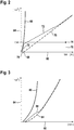
- FIG. 2 As an example, a diagram is shown in which the pedal force in the unit N (Newton) is shown on an x-axis 60 and the vehicle deceleration in the unit m / s 2 on a y-axis 64.
- a first curve 68 shows the deceleration of the vehicle in the normal “by-wire” operating mode.
- a second curve 70 shows the vehicle deceleration in the usual hydraulic fallback level, in which the driver (alone) builds up braking torque through muscle power. Accordingly, curve 70 is significantly flatter than curve 68. It crosses the zero line after a pedal force threshold value 66 and then rises essentially linearly.
- a third curve 72 shows the vehicle deceleration in the hydraulic fallback level, with the parking brake also being activated.
- the curve 72 rises after a pedal force threshold 78 steeply linear to then bend and continue to climb linearly. It can be seen that when the parking brake is activated, the vehicle deceleration increases very quickly, in order to then level off with an incline that is less than the normal fallback level. The rapid rise encourages the driver to continue braking because the vehicle reacts quickly and clearly to his braking request.
- the reference numerals 74 and 76 describe the legal minimum requirement according to which a minimum deceleration of the vehicle of 2.44 m / s 2 must be achieved with a pedal force of 500N.
- the brake pedal travel is plotted in mm on the x-axis 60;
- the vehicle deceleration in m / s 2 is again plotted on the y-axis 64.
- Curve 80 shows the deceleration behavior in the ("by-wire") normal operating mode, while curve 84 shows the deceleration behavior in the fallback level.
- Curve 88 shows the vehicle deceleration with the parking brake also activated. Compared to the normal fallback level, the vehicle deceleration starts with smaller brake pedal travel and initially increases more, so that the driver can see that the vehicle can still be braked - even if the pedal feel changes.
- Curve 90 shows the vehicle deceleration in the normal operating mode of the braking system, in which the driver's braking request is detected, from which a braking target torque is determined.
- the pressure supply device 5 is controlled accordingly by the control and regulating unit 12 in order to build up the brake pressure required for the braking torque in the wheel brakes 8, 9, 10, 11.
- Curve 94 shows the vehicle deceleration in the hydraulic fallback level (without activation of the auxiliary brake actuator). Curve 94 rises significantly less than curve 90, which means that in order to achieve the same deceleration as in normal operating mode, the driver must pedal further.
- Curves 100, 102, 104, 106, 108, 110 each show the vehicle decelerations in a sequence of brake pedal actuations by the driver.
- the parking brake is activated or activated when a first pedal travel threshold value 120 is reached.
- the parking brake is activated or activated at a second, higher pedal travel threshold value 124.
- the support by the additional brake actuator is preferably activated by an applicable travel threshold value "driver brakes" of the brake pedal (variable pedal travel threshold value). If this is not reached, the support will be withdrawn.
- a shutdown is preferably superimposed, which switches the activation of the additional brake actuator on or off depending on the vehicle deceleration. Is particularly preferred when exceeded If an upper limit of the vehicle deceleration is exceeded, the support is withdrawn. If the limit falls below a lower limit, the support is switched on again as long as the travel threshold is above "Driver brakes".
- the auxiliary brake actuator or the parking brake is preferably activated when the brake pedal travel is greater than the (currently current) pedal travel threshold value and the vehicle deceleration is less than a maximum value (e.g. lower limit value).
Claims (10)
- Système de freinage (1) électrohydraulique pour un véhicule automobile, comprenant :• un maître-cylindre de frein (2) actionnable par une pédale de frein (la) pour l'actionnement des freins de roue (8, 9, 10, 11) ;• un dispositif de mise à disposition de pression (5) à commande électronique ;• un actionneur de frein supplémentaire (50) à commande électronique ;• une unité de commande et de réglage (12) ;dans un mode de fonctionnement normal, l'unité de commande et de réglage (12) détectant une volonté de freinage du conducteur sur la base de l'actionnement de la pédale de frein (la) et commandant le dispositif de mise à disposition de pression (5) pour établir le couple de freinage au niveau des freins de roue (8, 9, 10, 11), sachant qu'en cas de dispositif de mise à disposition de pression (5) non activé ou non activable dans un plan de retour hydraulique, le conducteur obtient l'accès aux freins de roue (8, 9, 10, 11) et l'unité de commande et de réglage (12) commande l'actionneur de frein supplémentaire (50) pour établir le couple de freinage, l'unité de commande et de réglage (12) surveillant la course de pédale de frein ; caractérisé en ce que :
l'unité de commande et de réglage (12) commande, en cas de valeur seuil de course de pédale (120) prédéfinie atteinte, l'actionneur de frein supplémentaire pour établir le couple de freinage et qu'en cas de succession d'actionnements de pédale de frein par le conducteur, la valeur seuil de course de pédale (120) est au moins augmentée une fois. - Système de freinage (1) selon la revendication 1, en cas de succession d'actionnements de pédale de frein, la valeur seuil de course de pédale (120) étant repoussée vers des courses de pédale de frein toujours plus grandes.
- Système de freinage (1) selon la revendication 2, la succession de courses de pédale de frein accrues comportant pour l'essentiel les mêmes distances de course de pédale.
- Système de freinage (1) selon l'une quelconque des revendications 1 à 3, l'actionneur de frein supplémentaire (50) n'étant plus commandé après un nombre maximal prédéfini de commandes successives.
- Système de freinage (1) selon la revendication 4, le nombre maximal étant compris entre 30 et 50.
- Système de freinage (1) selon l'une quelconque des revendications 1 à 5, la puissance du couple de freinage produit par l'actionneur supplémentaire (50) étant pour l'essentiel identique.
- Système de freinage (1) selon l'une quelconque des revendications 1 à 6, l'actionneur de frein supplémentaire (50) étant réalisé sous la forme d'un frein de stationnement.
- Système de freinage (1) selon la revendication 7, le frein de stationnement étant réalisé de façon électromécanique.
- Système de freinage (1) selon la revendication 7 ou 8, le frein de stationnement étant disposé au niveau de l'essieu arrière du véhicule automobile.
- Procédé d'actionnement d'un système de freinage (1) électrohydraulique pour un véhicule automobile, comprenant :• un maître-cylindre de frein (2) actionnable par une pédale de frein (la) pour l'actionnement des freins de roue (8, 9, 10, 11) ;• un dispositif de mise à disposition de pression (5) à commande électronique ;• un actionneur de frein supplémentaire (50) à commande électronique ;dans un mode de fonctionnement normal, l'actionnement de la pédale de frein (la) par le conducteur détectant une volonté de freinage du conducteur et commandant le dispositif de mise à disposition de pression (5) pour établir le couple de freinage au niveau des freins de roue (8, 9, 10, 11), sachant qu'en cas de dispositif de mise à disposition de pression (5) non activé ou non activable dans un plan de retour hydraulique, le conducteur obtient l'accès aux freins de roue (8, 9, 10, 11) et l'actionneur de frein supplémentaire (50) est commandé pour établir le couple de freinage dans ce plan de retour hydraulique ;
dans le plan de retour hydraulique, la course de pédale de frein étant surveillée ;
caractérisé en ce que :
en cas de valeur seuil de course de pédale (120) prédéfinie atteinte, l'actionneur de frein supplémentaire (50) est commandé pour établir le couple de freinage et qu'en cas de succession d'actionnements de pédale de frein par le conducteur, la valeur seuil de course de pédale (120) est au moins augmentée une fois.
Applications Claiming Priority (2)
| Application Number | Priority Date | Filing Date | Title |
|---|---|---|---|
| DE102015219001.3A DE102015219001A1 (de) | 2015-10-01 | 2015-10-01 | Bremssystem und Verfahren zum Betreiben eines Bremssystems |
| PCT/EP2016/072403 WO2017055152A1 (fr) | 2015-10-01 | 2016-09-21 | Système de freinage et procédé de fonctionnement d'un système de freinage |
Publications (2)
| Publication Number | Publication Date |
|---|---|
| EP3356191A1 EP3356191A1 (fr) | 2018-08-08 |
| EP3356191B1 true EP3356191B1 (fr) | 2020-01-08 |
Family
ID=56958946
Family Applications (1)
| Application Number | Title | Priority Date | Filing Date |
|---|---|---|---|
| EP16767311.0A Active EP3356191B1 (fr) | 2015-10-01 | 2016-09-21 | Système de freinage et procédé de fonctionnement d'un système de freinage |
Country Status (7)
| Country | Link |
|---|---|
| US (1) | US11052891B2 (fr) |
| EP (1) | EP3356191B1 (fr) |
| JP (1) | JP6584647B2 (fr) |
| KR (1) | KR102113933B1 (fr) |
| CN (1) | CN108025718B (fr) |
| DE (1) | DE102015219001A1 (fr) |
| WO (1) | WO2017055152A1 (fr) |
Families Citing this family (17)
| Publication number | Priority date | Publication date | Assignee | Title |
|---|---|---|---|---|
| DE102016208396A1 (de) * | 2016-05-17 | 2017-11-23 | Robert Bosch Gmbh | Verfahren zum Überprüfen der Bremskraft in einem Fahrzeug |
| US10293799B2 (en) * | 2016-07-29 | 2019-05-21 | Ford Global Technologies, Llc | Methods for transitioning into reduced braking performance modes upon failure of a primary braking system |
| DE102017208178A1 (de) * | 2017-05-16 | 2018-11-22 | Continental Teves Ag & Co. Ohg | Bremsanlage sowie Verfahren zum Betrieb einer Bremsanlage |
| KR102042608B1 (ko) | 2018-09-06 | 2019-11-27 | 주식회사 만도 | 전자식 브레이크 시스템 |
| CN109398334A (zh) * | 2018-12-29 | 2019-03-01 | 芜湖伯特利汽车安全系统股份有限公司 | 一种基于驻车制动提升机动车行车制动安全的控制方法和系统 |
| DE202019101586U1 (de) * | 2019-02-12 | 2020-05-13 | Ipgate Ag | Packaging für ein Bremssystem |
| CN110103931B (zh) * | 2019-04-28 | 2024-01-19 | 北京百度网讯科技有限公司 | 一种检测车辆制动异常的方法、装置 |
| DE102019206668A1 (de) * | 2019-05-09 | 2020-11-12 | Robert Bosch Gmbh | Bremssystem für ein Fahrzeug und Verfahren zum Bremsen eines Fahrzeugs |
| KR20210099420A (ko) * | 2020-02-04 | 2021-08-12 | 주식회사 만도 | 전자식 브레이크 시스템 및 그 제어방법 |
| DE102020202477A1 (de) | 2020-02-26 | 2021-08-26 | Volkswagen Aktiengesellschaft | Sicherheitssystem für einen elektrisch antreibbaren Kraftwagen, Verfahren zum Betreiben eines solchen Sicherheitssystems sowie Kraftwagen |
| CN112644442B (zh) * | 2021-01-05 | 2022-03-08 | 中车株洲电力机车研究所有限公司 | 一种安全制动方法及装置 |
| DE102021205745A1 (de) | 2021-06-08 | 2022-12-08 | Continental Automotive Technologies GmbH | Bremssystem für Kraftfahrzeuge mit erweiterter Rückfallebene |
| CN113401142B (zh) * | 2021-07-13 | 2022-09-27 | 奇瑞新能源汽车股份有限公司 | 自动驾驶车辆的制动方法、装置、车辆及存储介质 |
| EP4147924A1 (fr) * | 2021-09-10 | 2023-03-15 | KNORR-BREMSE Systeme für Nutzfahrzeuge GmbH | Système de décélération |
| DE102022118673A1 (de) | 2022-07-26 | 2024-02-01 | Audi Aktiengesellschaft | Verfahren zum Betreiben einer Bremsanlage für ein Kraftfahrzeug sowie entsprechende Bremsanlage |
| CN115140001B (zh) * | 2022-08-17 | 2024-05-03 | 杭叉集团股份有限公司 | 一种重装电动叉车电液复合制动系统及控制方法 |
| DE102022209017B4 (de) | 2022-08-31 | 2024-03-28 | Volkswagen Aktiengesellschaft | Verfahren zur Aktivierung von Funktionen eines Kraftfahrzeugs und Kraftfahrzeug |
Family Cites Families (14)
| Publication number | Priority date | Publication date | Assignee | Title |
|---|---|---|---|---|
| GB2349676B (en) | 1999-05-05 | 2003-04-23 | Lucas Ind Plc | Improved back-up braking in vehicle braking systems |
| DE102006055765A1 (de) * | 2006-07-03 | 2008-01-31 | Continental Teves Ag & Co. Ohg | Verfahren zum Betrieb einer kombinierten Fahrzeugbremsanlage |
| EP2144795B1 (fr) * | 2007-04-05 | 2014-06-11 | Continental Teves AG & Co. oHG | Procédé de fonctionnement d'un système de freinage de véhicule et système de freinage de véhicule |
| JP5014916B2 (ja) * | 2007-08-10 | 2012-08-29 | 日立オートモティブシステムズ株式会社 | ブレーキ制御装置 |
| DE102010040097A1 (de) | 2009-09-11 | 2011-03-31 | Continental Teves Ag & Co. Ohg | Bremsanlage für Kraftfahrzeuge |
| DE102011076952A1 (de) * | 2010-06-10 | 2011-12-29 | Continental Teves Ag & Co. Ohg | Verfahren und Regelschaltung zur Regelung eines Bremssystems für Kraftfahrzeuge |
| DE102012210434A1 (de) * | 2011-07-29 | 2013-01-31 | Continental Teves Ag & Co. Ohg | Verfahren zum Betrieb einer Bremsanlage für Kraftfahrzeuge sowie Bremsanlage |
| DE102012201515A1 (de) * | 2012-02-02 | 2013-08-08 | Continental Teves Ag & Co. Ohg | Verfahren zum Betrieb einer Bremsanlage für Kraftfahrzeuge sowie Bremsanlage |
| DE102012201820A1 (de) * | 2012-02-07 | 2013-08-08 | Bayerische Motoren Werke Aktiengesellschaft | Elektrohydraulische by wire Bremseinrichtung und Verfahren zu deren Steuerung im Fehlerfall |
| DE102012212329A1 (de) * | 2012-07-13 | 2014-04-03 | Continental Teves Ag & Co. Ohg | Verfahren zum Sicherstellen einer Bremswirkung |
| DE102012215627A1 (de) | 2012-09-04 | 2014-03-06 | Continental Teves Ag & Co. Ohg | Bremsanlage für Kraftfahrzeuge sowie Verfahren zum Betrieb einer Bremsanlage |
| DE102013223861A1 (de) * | 2013-11-21 | 2015-05-21 | Continental Teves Ag & Co. Ohg | Bremsanlage für Kraftahrzeuge |
| DE102013227065B4 (de) * | 2013-12-23 | 2016-02-18 | Robert Bosch Gmbh | Hydraulisches Bremssystem mit erstem und zweitem Bremsdruckerzeuger sowie Verfahren zum Betreiben eines Bremssystems |
| CN104309597A (zh) * | 2014-09-26 | 2015-01-28 | 同济大学 | 一种液压式双电机驱动电子液压制动系统控制方法 |
-
2015
- 2015-10-01 DE DE102015219001.3A patent/DE102015219001A1/de not_active Withdrawn
-
2016
- 2016-09-21 WO PCT/EP2016/072403 patent/WO2017055152A1/fr unknown
- 2016-09-21 CN CN201680052612.2A patent/CN108025718B/zh active Active
- 2016-09-21 KR KR1020187006896A patent/KR102113933B1/ko active IP Right Grant
- 2016-09-21 EP EP16767311.0A patent/EP3356191B1/fr active Active
- 2016-09-21 JP JP2018512593A patent/JP6584647B2/ja active Active
-
2018
- 2018-03-29 US US15/940,313 patent/US11052891B2/en active Active
Non-Patent Citations (1)
| Title |
|---|
| None * |
Also Published As
| Publication number | Publication date |
|---|---|
| US11052891B2 (en) | 2021-07-06 |
| JP2018526280A (ja) | 2018-09-13 |
| WO2017055152A1 (fr) | 2017-04-06 |
| DE102015219001A1 (de) | 2017-04-06 |
| CN108025718A (zh) | 2018-05-11 |
| US20180222464A1 (en) | 2018-08-09 |
| JP6584647B2 (ja) | 2019-10-02 |
| EP3356191A1 (fr) | 2018-08-08 |
| CN108025718B (zh) | 2020-06-26 |
| KR102113933B1 (ko) | 2020-05-21 |
| KR20180039690A (ko) | 2018-04-18 |
Similar Documents
| Publication | Publication Date | Title |
|---|---|---|
| EP3356191B1 (fr) | Système de freinage et procédé de fonctionnement d'un système de freinage | |
| EP3558771B1 (fr) | Système de freinage doté de deux sources d'air comprimé et deux procédés de fonctionnement d'un système de freinage | |
| EP2379379B1 (fr) | Installation de freinage pour véhicule automobile et procédé pour sa commande | |
| EP2892770B1 (fr) | Installation de freinage pour véhicules automobiles et procédé pour faire fonctionner un système de freinage | |
| EP2707262B1 (fr) | Système de freinage hydraulique de véhicule comprenant un actionneur électromécanique et procédé permettant de faire fonctionner un tel système de freinage hydraulique de véhicule | |
| EP2611658B1 (fr) | Système de freinage pour véhicules automobiles | |
| EP2934969B1 (fr) | Système de freinage électrohydraulique pour véhicule et procédé de fonctionnement | |
| EP2934973B1 (fr) | Système de freinage électrohydraulique pour véhicule et procédé de fonctionnement | |
| WO2016096532A1 (fr) | Système de freinage pour véhicules automobiles | |
| WO2013131805A2 (fr) | Procédé de détermination d'une courbe caractéristique pression-volume d'un frein sur roue | |
| DE10010735A1 (de) | Elektronisch regelbares Bremsbetätigungssystem und Verfahren zur elektronisch regelbaren Bremsbetätigung für Fahrzeuge | |
| WO2015022264A1 (fr) | Système de freinage d'un véhicule automobile et procédé permettant de faire fonctionner ledit système | |
| DE102011085273A1 (de) | Bremsanlage für Kraftfahrzeuge | |
| WO2016120115A1 (fr) | Procédé permettant de faire fonctionner un système de freinage et système de freinage dans lequel le procédé est mis en œuvre | |
| DE102012025247A1 (de) | Elektrohydraulische Fahrzeug-Bremsanlage und Verfahren zum Betreiben derselben | |
| DE102016202224A1 (de) | Verfahren zum Betreiben einer Bremsanlage eines Fahrzeuges und Bremsanlage | |
| DE102016220752A1 (de) | Verfahren zum Betreiben eines Bremssystems und Bremssystem | |
| EP3600988B1 (fr) | Procédé permettant de faire fonctionner un système de freinage et système de freinage | |
| DE102017202361A1 (de) | Verfahren zum Betreiben einer Bremsanlage und Bremsanlage | |
| DE102017211807A1 (de) | Bremssystem mit primärer Bremsregeleinrichtung und Zusatzmodul | |
| DE102019206612B3 (de) | Verfahren zur Steuerung eines elektromechanischen Bremssystems sowie elektromechanisches Bremssystem | |
| WO2021063577A1 (fr) | Procédé de commande d'un système de freinage assisté externe à régulation électronique de patinage, en particulier pour un véhicule automobile, et système de freinage assisté externe à régulation électronique de patinage, en particulier pour un véhicule automobile | |
| DE102010039345A1 (de) | Brake-by-Wire-Bremssystem, zugehöriges Betriebsverfahren und Kraftfahrzeug | |
| WO2018137848A1 (fr) | Procédé permettant de faire fonctionner un frein de stationnement électromécanique ainsi que dispositif de commande pour un frein de stationnement, frein de stationnement et véhicule automobile | |
| WO2018184845A1 (fr) | Système de freinage |
Legal Events
| Date | Code | Title | Description |
|---|---|---|---|
| STAA | Information on the status of an ep patent application or granted ep patent |
Free format text: STATUS: THE INTERNATIONAL PUBLICATION HAS BEEN MADE |
|
| PUAI | Public reference made under article 153(3) epc to a published international application that has entered the european phase |
Free format text: ORIGINAL CODE: 0009012 |
|
| STAA | Information on the status of an ep patent application or granted ep patent |
Free format text: STATUS: REQUEST FOR EXAMINATION WAS MADE |
|
| 17P | Request for examination filed |
Effective date: 20180502 |
|
| AK | Designated contracting states |
Kind code of ref document: A1 Designated state(s): AL AT BE BG CH CY CZ DE DK EE ES FI FR GB GR HR HU IE IS IT LI LT LU LV MC MK MT NL NO PL PT RO RS SE SI SK SM TR |
|
| AX | Request for extension of the european patent |
Extension state: BA ME |
|
| RAP1 | Party data changed (applicant data changed or rights of an application transferred) |
Owner name: CONTINENTAL TEVES AG & CO. OHG |
|
| DAV | Request for validation of the european patent (deleted) | ||
| DAX | Request for extension of the european patent (deleted) | ||
| GRAP | Despatch of communication of intention to grant a patent |
Free format text: ORIGINAL CODE: EPIDOSNIGR1 |
|
| STAA | Information on the status of an ep patent application or granted ep patent |
Free format text: STATUS: GRANT OF PATENT IS INTENDED |
|
| INTG | Intention to grant announced |
Effective date: 20190522 |
|
| GRAJ | Information related to disapproval of communication of intention to grant by the applicant or resumption of examination proceedings by the epo deleted |
Free format text: ORIGINAL CODE: EPIDOSDIGR1 |
|
| STAA | Information on the status of an ep patent application or granted ep patent |
Free format text: STATUS: REQUEST FOR EXAMINATION WAS MADE |
|
| GRAP | Despatch of communication of intention to grant a patent |
Free format text: ORIGINAL CODE: EPIDOSNIGR1 |
|
| STAA | Information on the status of an ep patent application or granted ep patent |
Free format text: STATUS: GRANT OF PATENT IS INTENDED |
|
| INTG | Intention to grant announced |
Effective date: 20190913 |
|
| GRAS | Grant fee paid |
Free format text: ORIGINAL CODE: EPIDOSNIGR3 |
|
| GRAA | (expected) grant |
Free format text: ORIGINAL CODE: 0009210 |
|
| STAA | Information on the status of an ep patent application or granted ep patent |
Free format text: STATUS: THE PATENT HAS BEEN GRANTED |
|
| AK | Designated contracting states |
Kind code of ref document: B1 Designated state(s): AL AT BE BG CH CY CZ DE DK EE ES FI FR GB GR HR HU IE IS IT LI LT LU LV MC MK MT NL NO PL PT RO RS SE SI SK SM TR |
|
| REG | Reference to a national code |
Ref country code: GB Ref legal event code: FG4D Free format text: NOT ENGLISH |
|
| REG | Reference to a national code |
Ref country code: CH Ref legal event code: EP |
|
| REG | Reference to a national code |
Ref country code: DE Ref legal event code: R096 Ref document number: 502016008362 Country of ref document: DE |
|
| REG | Reference to a national code |
Ref country code: IE Ref legal event code: FG4D Free format text: LANGUAGE OF EP DOCUMENT: GERMAN |
|
| REG | Reference to a national code |
Ref country code: AT Ref legal event code: REF Ref document number: 1222315 Country of ref document: AT Kind code of ref document: T Effective date: 20200215 |
|
| REG | Reference to a national code |
Ref country code: NL Ref legal event code: MP Effective date: 20200108 |
|
| REG | Reference to a national code |
Ref country code: LT Ref legal event code: MG4D |
|
| PG25 | Lapsed in a contracting state [announced via postgrant information from national office to epo] |
Ref country code: PT Free format text: LAPSE BECAUSE OF FAILURE TO SUBMIT A TRANSLATION OF THE DESCRIPTION OR TO PAY THE FEE WITHIN THE PRESCRIBED TIME-LIMIT Effective date: 20200531 Ref country code: RS Free format text: LAPSE BECAUSE OF FAILURE TO SUBMIT A TRANSLATION OF THE DESCRIPTION OR TO PAY THE FEE WITHIN THE PRESCRIBED TIME-LIMIT Effective date: 20200108 Ref country code: FI Free format text: LAPSE BECAUSE OF FAILURE TO SUBMIT A TRANSLATION OF THE DESCRIPTION OR TO PAY THE FEE WITHIN THE PRESCRIBED TIME-LIMIT Effective date: 20200108 Ref country code: NO Free format text: LAPSE BECAUSE OF FAILURE TO SUBMIT A TRANSLATION OF THE DESCRIPTION OR TO PAY THE FEE WITHIN THE PRESCRIBED TIME-LIMIT Effective date: 20200408 Ref country code: NL Free format text: LAPSE BECAUSE OF FAILURE TO SUBMIT A TRANSLATION OF THE DESCRIPTION OR TO PAY THE FEE WITHIN THE PRESCRIBED TIME-LIMIT Effective date: 20200108 Ref country code: LT Free format text: LAPSE BECAUSE OF FAILURE TO SUBMIT A TRANSLATION OF THE DESCRIPTION OR TO PAY THE FEE WITHIN THE PRESCRIBED TIME-LIMIT Effective date: 20200108 |
|
| PG25 | Lapsed in a contracting state [announced via postgrant information from national office to epo] |
Ref country code: BG Free format text: LAPSE BECAUSE OF FAILURE TO SUBMIT A TRANSLATION OF THE DESCRIPTION OR TO PAY THE FEE WITHIN THE PRESCRIBED TIME-LIMIT Effective date: 20200408 Ref country code: SE Free format text: LAPSE BECAUSE OF FAILURE TO SUBMIT A TRANSLATION OF THE DESCRIPTION OR TO PAY THE FEE WITHIN THE PRESCRIBED TIME-LIMIT Effective date: 20200108 Ref country code: LV Free format text: LAPSE BECAUSE OF FAILURE TO SUBMIT A TRANSLATION OF THE DESCRIPTION OR TO PAY THE FEE WITHIN THE PRESCRIBED TIME-LIMIT Effective date: 20200108 Ref country code: IS Free format text: LAPSE BECAUSE OF FAILURE TO SUBMIT A TRANSLATION OF THE DESCRIPTION OR TO PAY THE FEE WITHIN THE PRESCRIBED TIME-LIMIT Effective date: 20200508 Ref country code: HR Free format text: LAPSE BECAUSE OF FAILURE TO SUBMIT A TRANSLATION OF THE DESCRIPTION OR TO PAY THE FEE WITHIN THE PRESCRIBED TIME-LIMIT Effective date: 20200108 Ref country code: GR Free format text: LAPSE BECAUSE OF FAILURE TO SUBMIT A TRANSLATION OF THE DESCRIPTION OR TO PAY THE FEE WITHIN THE PRESCRIBED TIME-LIMIT Effective date: 20200409 |
|
| REG | Reference to a national code |
Ref country code: DE Ref legal event code: R097 Ref document number: 502016008362 Country of ref document: DE |
|
| PG25 | Lapsed in a contracting state [announced via postgrant information from national office to epo] |
Ref country code: EE Free format text: LAPSE BECAUSE OF FAILURE TO SUBMIT A TRANSLATION OF THE DESCRIPTION OR TO PAY THE FEE WITHIN THE PRESCRIBED TIME-LIMIT Effective date: 20200108 Ref country code: DK Free format text: LAPSE BECAUSE OF FAILURE TO SUBMIT A TRANSLATION OF THE DESCRIPTION OR TO PAY THE FEE WITHIN THE PRESCRIBED TIME-LIMIT Effective date: 20200108 Ref country code: SK Free format text: LAPSE BECAUSE OF FAILURE TO SUBMIT A TRANSLATION OF THE DESCRIPTION OR TO PAY THE FEE WITHIN THE PRESCRIBED TIME-LIMIT Effective date: 20200108 Ref country code: CZ Free format text: LAPSE BECAUSE OF FAILURE TO SUBMIT A TRANSLATION OF THE DESCRIPTION OR TO PAY THE FEE WITHIN THE PRESCRIBED TIME-LIMIT Effective date: 20200108 Ref country code: ES Free format text: LAPSE BECAUSE OF FAILURE TO SUBMIT A TRANSLATION OF THE DESCRIPTION OR TO PAY THE FEE WITHIN THE PRESCRIBED TIME-LIMIT Effective date: 20200108 Ref country code: SM Free format text: LAPSE BECAUSE OF FAILURE TO SUBMIT A TRANSLATION OF THE DESCRIPTION OR TO PAY THE FEE WITHIN THE PRESCRIBED TIME-LIMIT Effective date: 20200108 Ref country code: RO Free format text: LAPSE BECAUSE OF FAILURE TO SUBMIT A TRANSLATION OF THE DESCRIPTION OR TO PAY THE FEE WITHIN THE PRESCRIBED TIME-LIMIT Effective date: 20200108 |
|
| PLBE | No opposition filed within time limit |
Free format text: ORIGINAL CODE: 0009261 |
|
| STAA | Information on the status of an ep patent application or granted ep patent |
Free format text: STATUS: NO OPPOSITION FILED WITHIN TIME LIMIT |
|
| 26N | No opposition filed |
Effective date: 20201009 |
|
| PG25 | Lapsed in a contracting state [announced via postgrant information from national office to epo] |
Ref country code: IT Free format text: LAPSE BECAUSE OF FAILURE TO SUBMIT A TRANSLATION OF THE DESCRIPTION OR TO PAY THE FEE WITHIN THE PRESCRIBED TIME-LIMIT Effective date: 20200108 |
|
| PG25 | Lapsed in a contracting state [announced via postgrant information from national office to epo] |
Ref country code: SI Free format text: LAPSE BECAUSE OF FAILURE TO SUBMIT A TRANSLATION OF THE DESCRIPTION OR TO PAY THE FEE WITHIN THE PRESCRIBED TIME-LIMIT Effective date: 20200108 Ref country code: PL Free format text: LAPSE BECAUSE OF FAILURE TO SUBMIT A TRANSLATION OF THE DESCRIPTION OR TO PAY THE FEE WITHIN THE PRESCRIBED TIME-LIMIT Effective date: 20200108 |
|
| REG | Reference to a national code |
Ref country code: CH Ref legal event code: PL |
|
| GBPC | Gb: european patent ceased through non-payment of renewal fee |
Effective date: 20200921 |
|
| REG | Reference to a national code |
Ref country code: BE Ref legal event code: MM Effective date: 20200930 |
|
| PG25 | Lapsed in a contracting state [announced via postgrant information from national office to epo] |
Ref country code: LU Free format text: LAPSE BECAUSE OF NON-PAYMENT OF DUE FEES Effective date: 20200921 |
|
| PG25 | Lapsed in a contracting state [announced via postgrant information from national office to epo] |
Ref country code: IE Free format text: LAPSE BECAUSE OF NON-PAYMENT OF DUE FEES Effective date: 20200921 Ref country code: LI Free format text: LAPSE BECAUSE OF NON-PAYMENT OF DUE FEES Effective date: 20200930 Ref country code: GB Free format text: LAPSE BECAUSE OF NON-PAYMENT OF DUE FEES Effective date: 20200921 Ref country code: CH Free format text: LAPSE BECAUSE OF NON-PAYMENT OF DUE FEES Effective date: 20200930 Ref country code: BE Free format text: LAPSE BECAUSE OF NON-PAYMENT OF DUE FEES Effective date: 20200930 |
|
| PG25 | Lapsed in a contracting state [announced via postgrant information from national office to epo] |
Ref country code: TR Free format text: LAPSE BECAUSE OF FAILURE TO SUBMIT A TRANSLATION OF THE DESCRIPTION OR TO PAY THE FEE WITHIN THE PRESCRIBED TIME-LIMIT Effective date: 20200108 Ref country code: MT Free format text: LAPSE BECAUSE OF FAILURE TO SUBMIT A TRANSLATION OF THE DESCRIPTION OR TO PAY THE FEE WITHIN THE PRESCRIBED TIME-LIMIT Effective date: 20200108 Ref country code: CY Free format text: LAPSE BECAUSE OF FAILURE TO SUBMIT A TRANSLATION OF THE DESCRIPTION OR TO PAY THE FEE WITHIN THE PRESCRIBED TIME-LIMIT Effective date: 20200108 |
|
| PG25 | Lapsed in a contracting state [announced via postgrant information from national office to epo] |
Ref country code: MK Free format text: LAPSE BECAUSE OF FAILURE TO SUBMIT A TRANSLATION OF THE DESCRIPTION OR TO PAY THE FEE WITHIN THE PRESCRIBED TIME-LIMIT Effective date: 20200108 Ref country code: MC Free format text: LAPSE BECAUSE OF FAILURE TO SUBMIT A TRANSLATION OF THE DESCRIPTION OR TO PAY THE FEE WITHIN THE PRESCRIBED TIME-LIMIT Effective date: 20200108 Ref country code: AL Free format text: LAPSE BECAUSE OF FAILURE TO SUBMIT A TRANSLATION OF THE DESCRIPTION OR TO PAY THE FEE WITHIN THE PRESCRIBED TIME-LIMIT Effective date: 20200108 |
|
| REG | Reference to a national code |
Ref country code: DE Ref legal event code: R081 Ref document number: 502016008362 Country of ref document: DE Owner name: CONTINENTAL AUTOMOTIVE TECHNOLOGIES GMBH, DE Free format text: FORMER OWNER: CONTINENTAL TEVES AG & CO. OHG, 60488 FRANKFURT, DE |
|
| REG | Reference to a national code |
Ref country code: AT Ref legal event code: MM01 Ref document number: 1222315 Country of ref document: AT Kind code of ref document: T Effective date: 20210921 |
|
| PG25 | Lapsed in a contracting state [announced via postgrant information from national office to epo] |
Ref country code: AT Free format text: LAPSE BECAUSE OF NON-PAYMENT OF DUE FEES Effective date: 20210921 |
|
| P01 | Opt-out of the competence of the unified patent court (upc) registered |
Effective date: 20230522 |
|
| PGFP | Annual fee paid to national office [announced via postgrant information from national office to epo] |
Ref country code: FR Payment date: 20230928 Year of fee payment: 8 Ref country code: DE Payment date: 20230930 Year of fee payment: 8 |
|
| REG | Reference to a national code |
Ref country code: DE Ref legal event code: R081 Ref document number: 502016008362 Country of ref document: DE Owner name: CONTINENTAL AUTOMOTIVE TECHNOLOGIES GMBH, DE Free format text: FORMER OWNER: CONTINENTAL AUTOMOTIVE TECHNOLOGIES GMBH, 30165 HANNOVER, DE |