EP3355436A1 - Elektrisches unterputz-installationsgerät mit ladefunktion für ein mobiles audio- und kommunikationsgerät - Google Patents
Elektrisches unterputz-installationsgerät mit ladefunktion für ein mobiles audio- und kommunikationsgerät Download PDFInfo
- Publication number
- EP3355436A1 EP3355436A1 EP18152548.6A EP18152548A EP3355436A1 EP 3355436 A1 EP3355436 A1 EP 3355436A1 EP 18152548 A EP18152548 A EP 18152548A EP 3355436 A1 EP3355436 A1 EP 3355436A1
- Authority
- EP
- European Patent Office
- Prior art keywords
- charging
- flush
- mobile
- mobile audio
- electrical
- Prior art date
- Legal status (The legal status is an assumption and is not a legal conclusion. Google has not performed a legal analysis and makes no representation as to the accuracy of the status listed.)
- Granted
Links
Images


Classifications
-
- H—ELECTRICITY
- H02—GENERATION; CONVERSION OR DISTRIBUTION OF ELECTRIC POWER
- H02J—ELECTRIC POWER NETWORKS; CIRCUIT ARRANGEMENTS OR SYSTEMS FOR SUPPLYING OR DISTRIBUTING ELECTRIC POWER; SYSTEMS FOR STORING ELECTRIC ENERGY
- H02J7/00—Circuit arrangements for charging or discharging batteries or for supplying loads from batteries
- H02J7/70—Circuit arrangements for charging or discharging batteries or for supplying loads from batteries characterised by the mechanical construction
- H02J7/731—Circuit arrangements for charging or discharging batteries or for supplying loads from batteries characterised by the mechanical construction specially adapted for holding portable devices containing batteries
-
- H—ELECTRICITY
- H02—GENERATION; CONVERSION OR DISTRIBUTION OF ELECTRIC POWER
- H02G—INSTALLATION OF ELECTRIC CABLES OR LINES, OR OF COMBINED OPTICAL AND ELECTRIC CABLES OR LINES
- H02G3/00—Installations of electric cables or lines or protective tubing therefor in or on buildings, equivalent structures or vehicles
- H02G3/02—Details
- H02G3/08—Distribution boxes; Connection or junction boxes
- H02G3/12—Distribution boxes; Connection or junction boxes for flush mounting
-
- H—ELECTRICITY
- H02—GENERATION; CONVERSION OR DISTRIBUTION OF ELECTRIC POWER
- H02G—INSTALLATION OF ELECTRIC CABLES OR LINES, OR OF COMBINED OPTICAL AND ELECTRIC CABLES OR LINES
- H02G3/00—Installations of electric cables or lines or protective tubing therefor in or on buildings, equivalent structures or vehicles
- H02G3/02—Details
- H02G3/08—Distribution boxes; Connection or junction boxes
- H02G3/14—Fastening of cover or lid to box
-
- H—ELECTRICITY
- H02—GENERATION; CONVERSION OR DISTRIBUTION OF ELECTRIC POWER
- H02G—INSTALLATION OF ELECTRIC CABLES OR LINES, OR OF COMBINED OPTICAL AND ELECTRIC CABLES OR LINES
- H02G3/00—Installations of electric cables or lines or protective tubing therefor in or on buildings, equivalent structures or vehicles
- H02G3/02—Details
- H02G3/08—Distribution boxes; Connection or junction boxes
- H02G3/18—Distribution boxes; Connection or junction boxes providing line outlets
Definitions
- the invention relates to a flush-mounted electrical installation device with charging function for a mobile audio and communication devices.
- Switch programs or programs of installation devices are often supplemented with charging functions for mobile devices.
- this describes DE 10 2010 005 393 A1 a flush-mounted installation device, which has a charger for a mobile audio device and a 230V electrical connection in the flush-mounted insert.
- the flush-mounted installation device is further equipped with a holder, with a central pane for receiving the mobile audio device and a cover frame and a printed circuit board, which ensures the electrical connection between the mobile audio device and the flush-mounted insert by means of several plug devices.
- the mobile device charging cradles or receivers are often designed so that the mobile devices take a slight reserve as they are placed in the shell, and so in the event of an accident wall-mounted installation device are inclined during the charging process of the wall.
- the invention has for its object to optimize the structure of the installation device so that damage to the mobile audio and communication device, especially during the charging process, is avoided when it is stored on the charging cradle or recording.
- the arranged on the cover or central pane of the installation device conditioning device can be executed according to the particular installation equipment flush-mounted program or switch or switch program in different designs and designs.
- the resilient, resilient contact surface of the abutment device, on which the mobile device comes to rest integrally integrally integrated into the central disc and also structurally, especially in terms of color, structure, gloss, materiality, not distinguishable from the surface of the central disc , So adapted to the respective switch or socket program of the installation device used.
- a stop is provided behind the contact surface, to which the contact surface can strike and the spring travel is limited so advantageously.
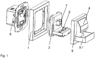
- Fig. 1 shows the electrical flush-mounted installation device according to the invention for receiving a mobile audio and communication device in an exploded view with a Unterputzdon 6, a cover 1, a charging device or charging cradle 2 and a can be applied to the charging cradle 2 central cover 9, also called central disk, with a receiving shaft 9.1, hereinafter also called holder, for a mobile audio and communication device.
- the charging cradle 2 has a stop 7 and a plug-in device 3, preferably designed as a plug connector, for connection to the mobile audio and communication device in order to charge it.
- the central disk 9 is designed in its design so that it forms a design cover for the charging tray 2 according to the switch or socket program used in each case.
- the central disk 9 is equipped with an integrated resilient abutment device 4, which is executable in different designs and designs, which are exemplified in Fig. 5 are shown.
- FIG. 2 3 is a perspective view of two exemplary flush-mounted electrical installation devices for receiving a mobile audio and communication device according to the present invention.
- the front side of the electrical flush-mounted installation device can be seen, which is covered by the central disk 9 with the receiving slot 9.1 for the mobile audio and communication device to be loaded.
- the plug-in device 3 of the charging device 2 is shown for connection to the mobile audio and communication device.
- a cover frame 1 encloses the central disk 9.
- Exemplary shows the Fig. 2 in each case a bearing device 4 formed from three parts, which according to a first embodiment a) have a wave-shaped and according to a second embodiment b) an angled cross-section or course.
- FIG. 3 is a side view of an exemplary electrical flush-mounted installation device shown for receiving the mobile audio and communication device according to the present invention and shows the spatial allocation of the above-mentioned flushing insert 6 to the central disk 9 including the resilient contact device 4 and the plug-in device 3 of the charging shell. 2
- the flush-mounted installation device is in turn completed by the cover 1.
- the stopper 7 is, preferably in the central region of the front panel of the charging tray 2, arranged.
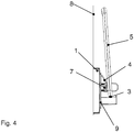
- Fig. 4 shows a side view through another exemplary flush-mounted electrical installation device for receiving the mobile audio and communication device 5 according to the present invention, in which the mobile audio and communication device 5 is connected to the connector 3 of the charging cradle 2.
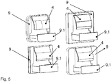
- Fig. 5 shows central disks 9 of various installation equipment programs for filing and loading of mobile audio and communication devices 5 according to the present invention.
- the central disks 9 shown here by way of example with the integrated resiliently designed contact devices 4 allow a shapely integration / integration of the proposed electrical flush-mounted installation device for receiving the mobile audio and communication device 5 in an installation device flush-mounted program respectively switch and socket flush-mounted Program and a combination with other devices, such as switches, buttons, dimmers, sockets of various switch and socket flush-mounted programs.
- cover frame 1 and central disk 2 are designed in accordance with the typical features of a special switch and socket flush-mounted program.
Landscapes
- Engineering & Computer Science (AREA)
- Architecture (AREA)
- Civil Engineering (AREA)
- Structural Engineering (AREA)
- Power Engineering (AREA)
- Charge And Discharge Circuits For Batteries Or The Like (AREA)
- Telephone Set Structure (AREA)
Abstract
Description
- Die Erfindung betrifft ein elektrisches Unterputz-Installationsgerät mit Ladefunktion für ein mobiles Audio- und Kommunikationsgeräte.
- Schalterprogramme bzw. Programme von Installationsgeräten werden oftmals mit Ladefunktionen für mobile Geräte ergänzt. Hier sind zahlreiche marktübliche Anwendungen bekannt, die das Laden der mobilen Geräte im Design des Schalter- und Steckdosenprogramms ermöglichen und so die Belegung einer Steckdose mit einem zusätzlichen Netzteil zum Laden des mobilen Gerätes vermeiden.
- Beispielsweise beschreibt die
DE 10 2010 005 393 A1 ein Unterputz-Installationsgerät, welches ein Ladegerät für ein mobiles Audiogerät sowie einen elektrischen 230V- Anschluss in dem Unterputz-Einsatz aufweist. Das Unterputz-Installationsgerät ist weiterhin mit einem Halter, mit einer Zentralscheibe für die Aufnahme des mobilen Audiogerätes sowie einem Abdeckrahmen und einer Leiterplatte, welche mittels mehrerer Steckvorrichtungen die elektrische Verbindung zwischen dem mobilen Audiogerät und dem Unterputz-Einsatz sicherstellt, ausgestattet. - Bei elektrischen Unterputz-Installationsgeräten eines Schalter- und Steckdosprogrammes zur Aufnahme und zum Laden der mobilen Audio- und Kommunikationsgerätes besteht prinzipiell das Problem, dass ein Herausfallen der Geräte aus der Aufnahme bzw. Ladeschale nicht auszuschließen ist.
- Um dies zu vermeiden und die mobilen Audio- und Kommunikationsgeräte vor Beschädigungen zu schützen, sind die Ladeschalen bzw. Aufnahmen für das mobile Gerät oft so konstruiert, dass die mobilen Geräte bei ihrem Einlegen in die Schale eine leichte Rücklagen einnehmen und so im Fall eines in der Wand installierten Installationsgerätes während dem Ladevorgang der Wand zugeneigt sind.
- Dies hat den Nachteil, dass die teilweise sehr hochwertigen Oberflächen der mobilen Geräte mit der Oberfläche der Wand in Berührung kommen und je nach Beschaffenheit der Wandoberfläche die Oberfläche des mobilen Gerätes oder die rückseitig angeordnete Kamera verkratzt oder beschädigt werden. Hat beispielsweise die Wandoberfläche eine sehr harte und raue Struktur, wie bei einem Quarz- oder Mineralputz, kann die anliegende Hochglanzoberfläche oder die anliegende Linse einer rückseitig angeordneten Kamera des mobilen Kommunikationsgerätes Schaden nehmen.
- Der Erfindung liegt die Aufgabe zugrunde, den Aufbau des Installationsgerätes so zu optimieren, dass eine Beschädigung des mobilen Audio- und Kommunikationsgerätes, insbesondere während des Ladevorganges, bei dessen Ablage auf der Ladeschale bzw. Aufnahme vermieden wird.
- Diese Aufgabe wird erfindungsgemäß gelöst durch ein elektrisches Unterputz-Installationsgerät zur Aufnahme eines mobilen Audio- und Kommunikationsgerätes
- mit einem ein Ladegerät und einen elektrischen Anschluss bis 250V beinhaltenden UP-Einsatz,
- mit einem Abdeckrahmen,
- mit einer Ladevorrichtung bzw. Ladeschale inklusive einer Steckvorrichtung für die Verbindung mit dem mobilen Audio- und Kommunikationsgerät zum Laden des Gerätes,
- mit einer auf die Ladeschale aufbringbaren Zentralabdeckung bzw. Zentralscheibe mit Halterung für das mobile Audio- und Kommunikationsgerät, und
- mit einer in der Abdeckung bzw. Zentralscheibe des Installationsgerätes integrierten bzw. angeformten elastischen federnden Anlagevorrichtung, welche vorzugsweise aus dem auch für die Zentralscheibe verwendeten Kunststoff gebildet ist.
- Die an der Abdeckung bzw. Zentralscheibe des Installationsgerätes angeordnete Anlagevorrichtung kann entsprechend des jeweils verwendeten Installationsgeräte-Unterputz-Programm bzw. Schalter- oder Schalterprogrammes in unterschiedlichen Designs und Gestaltungsformen ausführbar sein.
- Erfindungsgemäß ist die federnde, elastische Anlagefläche der Anlagevorrichtung, an welcher das mobile Gerät zur Anlage kommt, in vorteilhafter Weise einteilig in die Zentralscheibe integriert und auch gestalterisch, insbesondere in Bezug auf Farbe, Struktur, Glanzgrad, Materialität, nicht von der Oberfläche der Zentralscheibe unterscheidbar, also an das jeweilige Schalter- oder Steckdosenprogramm des verwendeten Installationsgerätes angepasst.
- Um ein unerwünschte Verformung der federnden elastische Anlagefläche weiter als vorgesehen zu vermeiden und das mobile Gerät keinen Kontakt mit der Wandoberfläche bekommt, ist hinter der Anlagefläche ein Anschlag vorgesehen, an den die Anlagefläche anschlagen kann und der Federweg so in vorteilhafter Weise begrenzt wird.
- Weitere vorteilhafte und zweckmäßige Ausgestaltungen und Verbesserungen des erfindungsgemäßen elektrischen Installationsgerätes zur Aufnahme des mobilen Audio- und Kommunikationsgerätes sind in den Unteransprüchen und an Hand der in der Zeichnungen dargestellten Ausführungsbeispiele erläutert.
- Es zeigen:
- Fig. 1
- eine Explosionsdarstellung eines beispielhaft ausgeführten erfindungsgemäßen elektrischen Unterputz-Installationsgerätes zur Aufnahme eines mobilen Audio- und Kommunikationsgerätes,
- Fig. 2
- eine perspektivische Sicht auf zwei beispielhafte elektrische Unterputz-Installationsgeräte zur Aufnahme eines mobilen Audio- und Kommunikationsgerätes,
- Fig. 3
- eine Seitenansicht des beispielhaften elektrischen Unterputz-Installationsgerätes zur Aufnahme des mobilen Audio- und Kommunikationsgerätes gemäß vorliegender Erfindung, wobei das mobilen Audio- und Kommunikationsgerätes sich noch nicht in der Ladeschale bzw. im Aufnahmeschacht der Halterung befindet,
- Fig. 4
- eine Seitenansicht eines weiteren beispielhaften elektrischen Unterputz-Installationsgerätes zur Aufnahme des mobilen Audio- und Kommunikationsgerätes gemäß vorliegender Erfindung, wobei sich das mobile Audio- und Kommunikationsgerät im Aufnahmeschacht Zentralabdeckung befindet, und
- Fig. 5
- beispielhafte Zentralscheiben verschiedener Installationsgeräte-Programme zur Ablage und zum Laden von mobilen Audio- und Kommunikationsgeräte gemäß der vorliegenden Erfindung.
-
Fig. 1 zeigt das erfindungsgemäße elektrische Unterputz-Installationsgerät zur Aufnahme eines mobilen Audio- und Kommunikationsgerätes in einer Explosionsdarstellung mit einem Unterputzeinsatz 6, einem Abdeckrahmen 1, einer Ladevorrichtung bzw. Ladeschale 2 und einer auf die Ladeschale 2 aufbringbaren Zentralabdeckung 9, auch Zentralscheibe genannt, mit einem Aufnahmeschacht 9.1, nachfolgend auch Halterung genannt, für ein mobiles Audio- und Kommunikationsgerät. - Die Ladeschale 2 weist einen Anschlag 7 und eine, vorzugsweise als Steckverbinder ausgeführte Steckvorrichtung 3 für die Verbindung mit dem mobilen Audio- und Kommunikationsgerät auf, um dieses aufzuladen.
- Die Zentralscheibe 9 ist in ihrer Ausführung so gestaltet, dass sie eine Designabdeckung für die Ladeschale 2 entsprechend dem jeweils verwendeten Schalter- oder Steckdosenprogramm bildet.
- Um das zum Laden im Aufnahmeschacht der Zentralscheibe 9 abgelegte mobile Gerät vor Beschädigungen zu schützen, ist die Zentralscheibe 9 mit einer integrierten, federnde Anlagevorrichtung 4 ausgestattet, die in unterschiedlichen Designs und Gestaltungsformen ausführbar ist, welche beispielhaft in
Fig. 5 gezeigt sind. - In
Fig. 2 ist eine perspektivische Sicht auf zwei beispielhafte elektrische Unterputz-Installationsgeräte zur Aufnahme eines mobilen Audio- und Kommunikationsgerätes gemäß vorliegender Erfindung gezeigt. - Dabei ist die Frontseite des elektrischen Unterputz-Installationsgerätes zu erkennen, welche von der Zentralscheibe 9 mit dem Aufnahmeschacht 9.1 für das zu ladende mobile Audio- und Kommunikationsgerät abgedeckt ist.
- Im Aufnahmeschacht 9.1. ist die Steckvorrichtung 3 der Ladevorrichtung 2 für die Verbindung mit dem mobilen Audio- und Kommunikationsgerät dargestellt.
- Ein Abdeckrahmen 1 umschließt die Zentralscheibe 9.
- Nicht zu erkennen ist der Unterputz-Einsatz des Unterputz-Installationsgerätes, welcher in den
Figuren 1 und3 dargestellt ist. Im Unterputzeinsatz 6 sind ein elektrischer 230V- Anschluss und die Ladeelektronik der Ladevorrichtung 2 für ein energieoptimiertes Aufladen von mobilen Audio- und Kommunikationsgeräten integriert. - Um das zum Laden im Aufnahmeschacht 9.1 der Designabdeckung 9 abgelegte mobile Gerät vor Beschädigungen zu schützen, ist diese mit federnden Anlagevorrichtung 4 ausgestattet, die in unterschiedlichen Designs und Gestaltungsformen ausführbar ist.
- Beispielhaft zeigt die
Fig. 2 jeweils eine aus drei Teilen gebildete Anlagevorrichtung 4, welche gemäß einer ersten Ausführungsform a) einen wellenförmig gestalteten und gemäß einer zweiten Ausführungsform b) einen abgewinkelten Querschnitt bzw. Verlauf aufweisen. - In
Fig. 3 ist eine Seitenansicht durch ein beispielhaftes elektrisches Unterputz-Installationsgerät zur Aufnahme des mobilen Audio- und Kommunikationsgerätes gemäß vorliegender Erfindung dargestellt und zeigt die räumliche Zuordnung des vorstehend bereits erwähnten Unterputzeinsatzes 6 zur Zentralscheibe 9 inklusive der federnden Anlagevorrichtung 4 und der Steckvorrichtung 3 der Ladeschale 2. - Das Unterputz-Installationsgerät wird wiederum durch den Abdeckrahmen 1 komplettiert.
- Zur Verbesserung der Anlagefunktion des im Aufnahmeschacht der Zentralscheibe 9 abgelegten mobilen Gerätes befindet sich als zusätzlicher Puffer der Anschlag 7, an dem die Anlagefläche der Anlagevorrichtung 4 anschlagen kann. Der Anschlag 7 ist, vorzugsweise im mittleren Bereich der Frontplatte der Ladeschale 2, angeordnet.
-
Fig. 4 zeigt eine Seitenansicht durch ein weiteres beispielhaftes elektrisches Unterputz-Installationsgerät zur Aufnahme des mobilen Audio- und Kommunikationsgerätes 5 gemäß vorliegender Erfindung, bei welchem das mobile Audio- und Kommunikationsgerät 5 mit der Steckverbindung 3 der Ladeschale 2 verbunden ist. - Auch hier ist der auf der Frontplatte der Ladeschale 9 befindliche Anschlag 7 zu erkennen, welcher verhindert, dass sich die Anlagefläche der elastischen Anlagevorrichtung 4 während der Ablage des mobilen Gerätes 5 weiter als vorgesehen verformt, den Federweg der Anlagevorrichtung 4 begrenzt und das mobile Gerät 5 Kontakt mit der Wandoberfläche 8 bekommt.
-
Fig. 5 zeigt Zentralscheiben 9 verschiedener Installationsgeräte-Programme zur Ablage und zum Laden von mobilen Audio- und Kommunikationsgeräte 5 gemäß der vorliegenden Erfindung. Die hier beispielhaft dargestellten Zentralscheiben 9 mit den den integrierten federnd gestalteten Anlagevorrichtungen 4 ermöglichen eine formschöne Einbindung/Integration des vorgeschlagenen elektrischen Unterputz-Installationsgerätes zur Aufnahme des mobilen Audio- und Kommunikationsgerätes 5 in ein Installationsgeräte-Unterputz-Programm respektive Schalter- und Steckdosen-Unterputz-Programm sowie eine Kombination mit weiteren Geräten, beispielsweise Schaltern, Tastern, Dimmern, Steckdosen verschiedener Schalter- und Steckdosen-Unterputz-Programme. - Dazu sind Abdeckrahmen 1 und Zentralscheibe 2 gemäß den typischen Merkmalen eines speziellen Schalter- und Steckdosen-Unterputz-Programms gestaltet.
-
- 1
- Abdeckrahmen
- 2
- Ladeschale, Ladevorrichtung
- 3
- Steckverbinder, Steckvorrichtung der Ladevorrichtung für die Verbindung mit dem mobilen Audio- und Kommunikationsgerät, angeordnet im Aufnahmeschacht
- 4
- federnde Anlagevorrichtung
- 5
- mobiles Audio- und Kommunikationsgerät
- 6
- Unterputzeinsatz mit integrierter Ladefunktion
- 7
- Anschlag auf der Ladeschale, Ladevorrichtung
- 8
- Wandoberfläche
- 9
- Zentralscheibe, Zentralabdeckung, Designabdeckung
- 9.1
- Aufnahmeschacht, Halterung für ein mobiles Audio- und Kommunikationsgerät
Claims (6)
- Elektrisches Unterputz-Installationsgerät zur Aufnahme eines mobilen Audio- und Kommunikationsgerätes (5),- mit einem ein Ladegerät und einen elektrischen Anschluss bis 250V beinhaltenden UP-Einsatz (6),- mit einem Abdeckrahmen (1),- mit einer Ladevorrichtung bzw. Ladeschale (2) inklusive einer Steckvorrichtung (3) für die Verbindung mit dem mobilen Audio- und Kommunikationsgerät zum Laden des Gerätes (5), und- mit einer auf die Ladeschale (2) aufbringbaren Zentralabdeckung (9),dadurch gekennzeichnet, dass die Zentralabdeckung (9) mit einer federnden elastische Anlagevorrichtung (4) ausgestattet ist, an der das mobile Gerät (5) zur Anlage kommt.
- Elektrisches Unterputz-Installationsgerät nach Anspruch 1, dadurch gekennzeichnet, dass hinter der federnden elastischen Anlagefläche der Anlagevorrichtung (4) ein Anschlag (7) zur Begrenzung des Federweges der Anlagefläche der Anlagevorrichtung (4) vorgesehen ist.
- Elektrisches Unterputz-Installationsgerät nach Anspruch 2, dadurch gekennzeichnet, dass der Anschlag (7) im mittleren Bereich der Frontplatte der Ladeschale (2) angeordnet ist.
- Elektrisches Unterputz-Installationsgerät nach einem der vorstehenden Ansprüche, dadurch gekennzeichnet, dass die federnde elastische Anlagefläche der Anlagevorrichtung (4), an welchem das mobile Gerät (5) zur Anlage kommt, einteilig in die Zentralabdeckung (9) so integriert ist, dass diese in Bezug auf die Ausgestaltung seiner Oberflächenbeschaffenheit nicht von der Oberfläche der Zentralabdeckung (9) unterscheidbar ist.
- Elektrisches Unterputz-Installationsgerät nach einem der vorstehenden Ansprüche, dadurch gekennzeichnet, die an der Zentralabdeckung (9) des Installationsgerätes befindliche Anlagevorrichtung (4) bezüglich Material, Farbe und/oder Oberflächenstruktur entsprechend an das jeweils verwendeten Installationsgeräte-Programm bzw. Schalter- oder Steckdosenprogramm angepasst ist.
- Elektrisches Unterputz-Installationsgerät nach einem der vorstehenden Ansprüchen, dadurch gekennzeichnet, dass die Zentralabdeckung (9) in unterschiedlichen Designs und Gestaltungsformen ausführbar ist und in ihrer Ausführung so gestaltet ist, dass sie eine Designabdeckung (9) für die Ladeschale (2) entsprechend dem jeweils verwendeten Schalter- oder Steckdosenprogramm bildet.
Applications Claiming Priority (1)
| Application Number | Priority Date | Filing Date | Title |
|---|---|---|---|
| DE102017101382.2A DE102017101382A1 (de) | 2017-01-25 | 2017-01-25 | Elektrisches Unterputz-Installationsgerät mit Ladefunktion für ein mobiles Audio- und Kommunikationsgerät |
Publications (2)
| Publication Number | Publication Date |
|---|---|
| EP3355436A1 true EP3355436A1 (de) | 2018-08-01 |
| EP3355436B1 EP3355436B1 (de) | 2020-11-04 |
Family
ID=61131938
Family Applications (1)
| Application Number | Title | Priority Date | Filing Date |
|---|---|---|---|
| EP18152548.6A Active EP3355436B1 (de) | 2017-01-25 | 2018-01-19 | Elektrisches unterputz-installationsgerät mit ladefunktion für ein mobiles audio- und kommunikationsgerät |
Country Status (2)
| Country | Link |
|---|---|
| EP (1) | EP3355436B1 (de) |
| DE (1) | DE102017101382A1 (de) |
Citations (7)
| Publication number | Priority date | Publication date | Assignee | Title |
|---|---|---|---|---|
| US4335863A (en) * | 1980-03-28 | 1982-06-22 | Rapps John W | Holding device for attachment to electrical installations |
| US20050109528A1 (en) * | 2003-09-16 | 2005-05-26 | Mallen Kenneth J. | Cover plate |
| EP1998423A2 (de) * | 2007-05-28 | 2008-12-03 | Sony Ericsson Mobile Communications Japan, Inc. | Kontaktlose Stromübertragungsvorrichtung |
| DE102009017265A1 (de) * | 2009-04-11 | 2010-10-21 | Abb Ag | Elektrisches Installationsgerät mit Ladegerät für ein Mobiltelefon |
| EP2256896A2 (de) * | 2009-05-30 | 2010-12-01 | Abb Ag | Elektrisches Installationsgerät mit Ladegerät für ein Mobiltelefon |
| DE102010005393A1 (de) * | 2010-01-22 | 2011-07-28 | Abb Ag, 68309 | Elektrisches Unterputz-Installationsgerät mit Ladegerät für ein mobiles Audio- und Kommunikationsgerät |
| EP2523282A2 (de) * | 2011-05-13 | 2012-11-14 | Abb Ag | Zentralscheibe eines elektrischen Installationsgerätes zum Ablegen und elektrischen Aufladen eines mobilen Audio- und Kommunikationsgerätes |
-
2017
- 2017-01-25 DE DE102017101382.2A patent/DE102017101382A1/de not_active Withdrawn
-
2018
- 2018-01-19 EP EP18152548.6A patent/EP3355436B1/de active Active
Patent Citations (7)
| Publication number | Priority date | Publication date | Assignee | Title |
|---|---|---|---|---|
| US4335863A (en) * | 1980-03-28 | 1982-06-22 | Rapps John W | Holding device for attachment to electrical installations |
| US20050109528A1 (en) * | 2003-09-16 | 2005-05-26 | Mallen Kenneth J. | Cover plate |
| EP1998423A2 (de) * | 2007-05-28 | 2008-12-03 | Sony Ericsson Mobile Communications Japan, Inc. | Kontaktlose Stromübertragungsvorrichtung |
| DE102009017265A1 (de) * | 2009-04-11 | 2010-10-21 | Abb Ag | Elektrisches Installationsgerät mit Ladegerät für ein Mobiltelefon |
| EP2256896A2 (de) * | 2009-05-30 | 2010-12-01 | Abb Ag | Elektrisches Installationsgerät mit Ladegerät für ein Mobiltelefon |
| DE102010005393A1 (de) * | 2010-01-22 | 2011-07-28 | Abb Ag, 68309 | Elektrisches Unterputz-Installationsgerät mit Ladegerät für ein mobiles Audio- und Kommunikationsgerät |
| EP2523282A2 (de) * | 2011-05-13 | 2012-11-14 | Abb Ag | Zentralscheibe eines elektrischen Installationsgerätes zum Ablegen und elektrischen Aufladen eines mobilen Audio- und Kommunikationsgerätes |
Also Published As
| Publication number | Publication date |
|---|---|
| EP3355436B1 (de) | 2020-11-04 |
| DE102017101382A1 (de) | 2018-07-26 |
Similar Documents
| Publication | Publication Date | Title |
|---|---|---|
| DE102015222685B4 (de) | Ablage zur Aufnahme wenigstens eines mobilen Endgerätes | |
| DE102014117694A1 (de) | Mobiltelefonhalter für ein Fahrzeug | |
| DE202005002921U1 (de) | Verbindungssystem, insbesondere elektrisches Verbindungssystem | |
| DE102015002313A1 (de) | Batterieladegeräte | |
| DE102007063585A1 (de) | Elektrisches Installationsgerät | |
| WO1997019501A1 (de) | Zwischenstecker für aufladbare elektrogeräte | |
| DE112014001356T5 (de) | Montagestruktur einer elektronischen Komponente, elektrischer Verteilerkasten und elektronische Komponente | |
| DE102010005393B4 (de) | Elektrisches Unterputz-Installationsgerät mit Ladegerät für ein mobiles Audio- und Kommunikationsgerät | |
| DE202007019214U1 (de) | Netzstecker | |
| DE102020133491B3 (de) | Elektrisches/elektronisches Installationsgerät | |
| EP3355436A1 (de) | Elektrisches unterputz-installationsgerät mit ladefunktion für ein mobiles audio- und kommunikationsgerät | |
| DE202018101278U1 (de) | Steckverbindermodul für einen modularen Industriesteckverbinder zur Übertragung hoher Datenraten | |
| DE102012013317A1 (de) | Fahrzeugdatenaufzeichnungsgerät zum Einbau in ein Kraftfahrzeug | |
| DE202017101832U1 (de) | Elektrisches Unterputz-Installationsgerät mit Ladefunktion für ein mobiles Audio- und Kommunikationsgerät | |
| EP2503517B1 (de) | Fahrzeugdatenaufzeichnungsvorrichtung | |
| DE102007030422B4 (de) | Halterung zur lösbaren Befestigung einer Verkleidungsplatte in einem Luftfahrzeug | |
| DE202014100984U1 (de) | Elektrisches Unterputz-Installationsgerät für die Herstellung einer Datenübertragungsverbindung zwischen einem mobilen Audiogerät und einem stationären Musikwiedergabegerät | |
| DE102008064442A1 (de) | Elektrisches Installationsgerät | |
| DE102016117451A1 (de) | Elektronikgehäuse | |
| DE102013203920A1 (de) | Elektromechanische Verbindungsvorrichtung | |
| DE69812307T2 (de) | Verbessertes Gehäuse für kleine Gegenstände | |
| EP2073314A1 (de) | Anordnung zum elektrisch leitenden Verbinden von elektrischen Leltern | |
| DE202018106611U1 (de) | Datenübertragungs- und/oder Ladekabel | |
| DE102017111755B3 (de) | Elektrisches Installationsgerät | |
| DE102018109601B4 (de) | Schaltschrankanordnung mit Schutzleiterfunktion |
Legal Events
| Date | Code | Title | Description |
|---|---|---|---|
| PUAI | Public reference made under article 153(3) epc to a published international application that has entered the european phase |
Free format text: ORIGINAL CODE: 0009012 |
|
| STAA | Information on the status of an ep patent application or granted ep patent |
Free format text: STATUS: THE APPLICATION HAS BEEN PUBLISHED |
|
| AK | Designated contracting states |
Kind code of ref document: A1 Designated state(s): AL AT BE BG CH CY CZ DE DK EE ES FI FR GB GR HR HU IE IS IT LI LT LU LV MC MK MT NL NO PL PT RO RS SE SI SK SM TR |
|
| AX | Request for extension of the european patent |
Extension state: BA ME |
|
| RIN1 | Information on inventor provided before grant (corrected) |
Inventor name: LANGE, MANFRED Inventor name: MRKAJIC, OLIVER Inventor name: THINIUS, DOERTE |
|
| STAA | Information on the status of an ep patent application or granted ep patent |
Free format text: STATUS: REQUEST FOR EXAMINATION WAS MADE |
|
| 17P | Request for examination filed |
Effective date: 20190122 |
|
| RBV | Designated contracting states (corrected) |
Designated state(s): AL AT BE BG CH CY CZ DE DK EE ES FI FR GB GR HR HU IE IS IT LI LT LU LV MC MK MT NL NO PL PT RO RS SE SI SK SM TR |
|
| GRAP | Despatch of communication of intention to grant a patent |
Free format text: ORIGINAL CODE: EPIDOSNIGR1 |
|
| STAA | Information on the status of an ep patent application or granted ep patent |
Free format text: STATUS: GRANT OF PATENT IS INTENDED |
|
| INTG | Intention to grant announced |
Effective date: 20200602 |
|
| GRAS | Grant fee paid |
Free format text: ORIGINAL CODE: EPIDOSNIGR3 |
|
| GRAA | (expected) grant |
Free format text: ORIGINAL CODE: 0009210 |
|
| STAA | Information on the status of an ep patent application or granted ep patent |
Free format text: STATUS: THE PATENT HAS BEEN GRANTED |
|
| AK | Designated contracting states |
Kind code of ref document: B1 Designated state(s): AL AT BE BG CH CY CZ DE DK EE ES FI FR GB GR HR HU IE IS IT LI LT LU LV MC MK MT NL NO PL PT RO RS SE SI SK SM TR |
|
| REG | Reference to a national code |
Ref country code: GB Ref legal event code: FG4D Free format text: NOT ENGLISH |
|
| REG | Reference to a national code |
Ref country code: CH Ref legal event code: EP |
|
| REG | Reference to a national code |
Ref country code: AT Ref legal event code: REF Ref document number: 1332081 Country of ref document: AT Kind code of ref document: T Effective date: 20201115 |
|
| REG | Reference to a national code |
Ref country code: IE Ref legal event code: FG4D Free format text: LANGUAGE OF EP DOCUMENT: GERMAN |
|
| REG | Reference to a national code |
Ref country code: DE Ref legal event code: R096 Ref document number: 502018002870 Country of ref document: DE |
|
| REG | Reference to a national code |
Ref country code: NL Ref legal event code: FP |
|
| PG25 | Lapsed in a contracting state [announced via postgrant information from national office to epo] |
Ref country code: RS Free format text: LAPSE BECAUSE OF FAILURE TO SUBMIT A TRANSLATION OF THE DESCRIPTION OR TO PAY THE FEE WITHIN THE PRESCRIBED TIME-LIMIT Effective date: 20201104 Ref country code: PT Free format text: LAPSE BECAUSE OF FAILURE TO SUBMIT A TRANSLATION OF THE DESCRIPTION OR TO PAY THE FEE WITHIN THE PRESCRIBED TIME-LIMIT Effective date: 20210304 Ref country code: FI Free format text: LAPSE BECAUSE OF FAILURE TO SUBMIT A TRANSLATION OF THE DESCRIPTION OR TO PAY THE FEE WITHIN THE PRESCRIBED TIME-LIMIT Effective date: 20201104 Ref country code: NO Free format text: LAPSE BECAUSE OF FAILURE TO SUBMIT A TRANSLATION OF THE DESCRIPTION OR TO PAY THE FEE WITHIN THE PRESCRIBED TIME-LIMIT Effective date: 20210204 Ref country code: GR Free format text: LAPSE BECAUSE OF FAILURE TO SUBMIT A TRANSLATION OF THE DESCRIPTION OR TO PAY THE FEE WITHIN THE PRESCRIBED TIME-LIMIT Effective date: 20210205 |
|
| PG25 | Lapsed in a contracting state [announced via postgrant information from national office to epo] |
Ref country code: ES Free format text: LAPSE BECAUSE OF FAILURE TO SUBMIT A TRANSLATION OF THE DESCRIPTION OR TO PAY THE FEE WITHIN THE PRESCRIBED TIME-LIMIT Effective date: 20201104 Ref country code: SE Free format text: LAPSE BECAUSE OF FAILURE TO SUBMIT A TRANSLATION OF THE DESCRIPTION OR TO PAY THE FEE WITHIN THE PRESCRIBED TIME-LIMIT Effective date: 20201104 Ref country code: IS Free format text: LAPSE BECAUSE OF FAILURE TO SUBMIT A TRANSLATION OF THE DESCRIPTION OR TO PAY THE FEE WITHIN THE PRESCRIBED TIME-LIMIT Effective date: 20210304 Ref country code: LV Free format text: LAPSE BECAUSE OF FAILURE TO SUBMIT A TRANSLATION OF THE DESCRIPTION OR TO PAY THE FEE WITHIN THE PRESCRIBED TIME-LIMIT Effective date: 20201104 Ref country code: PL Free format text: LAPSE BECAUSE OF FAILURE TO SUBMIT A TRANSLATION OF THE DESCRIPTION OR TO PAY THE FEE WITHIN THE PRESCRIBED TIME-LIMIT Effective date: 20201104 Ref country code: BG Free format text: LAPSE BECAUSE OF FAILURE TO SUBMIT A TRANSLATION OF THE DESCRIPTION OR TO PAY THE FEE WITHIN THE PRESCRIBED TIME-LIMIT Effective date: 20210204 |
|
| REG | Reference to a national code |
Ref country code: LT Ref legal event code: MG9D |
|
| PG25 | Lapsed in a contracting state [announced via postgrant information from national office to epo] |
Ref country code: HR Free format text: LAPSE BECAUSE OF FAILURE TO SUBMIT A TRANSLATION OF THE DESCRIPTION OR TO PAY THE FEE WITHIN THE PRESCRIBED TIME-LIMIT Effective date: 20201104 |
|
| PG25 | Lapsed in a contracting state [announced via postgrant information from national office to epo] |
Ref country code: SK Free format text: LAPSE BECAUSE OF FAILURE TO SUBMIT A TRANSLATION OF THE DESCRIPTION OR TO PAY THE FEE WITHIN THE PRESCRIBED TIME-LIMIT Effective date: 20201104 Ref country code: RO Free format text: LAPSE BECAUSE OF FAILURE TO SUBMIT A TRANSLATION OF THE DESCRIPTION OR TO PAY THE FEE WITHIN THE PRESCRIBED TIME-LIMIT Effective date: 20201104 Ref country code: LT Free format text: LAPSE BECAUSE OF FAILURE TO SUBMIT A TRANSLATION OF THE DESCRIPTION OR TO PAY THE FEE WITHIN THE PRESCRIBED TIME-LIMIT Effective date: 20201104 Ref country code: CZ Free format text: LAPSE BECAUSE OF FAILURE TO SUBMIT A TRANSLATION OF THE DESCRIPTION OR TO PAY THE FEE WITHIN THE PRESCRIBED TIME-LIMIT Effective date: 20201104 Ref country code: EE Free format text: LAPSE BECAUSE OF FAILURE TO SUBMIT A TRANSLATION OF THE DESCRIPTION OR TO PAY THE FEE WITHIN THE PRESCRIBED TIME-LIMIT Effective date: 20201104 Ref country code: SM Free format text: LAPSE BECAUSE OF FAILURE TO SUBMIT A TRANSLATION OF THE DESCRIPTION OR TO PAY THE FEE WITHIN THE PRESCRIBED TIME-LIMIT Effective date: 20201104 |
|
| REG | Reference to a national code |
Ref country code: DE Ref legal event code: R097 Ref document number: 502018002870 Country of ref document: DE |
|
| PG25 | Lapsed in a contracting state [announced via postgrant information from national office to epo] |
Ref country code: DK Free format text: LAPSE BECAUSE OF FAILURE TO SUBMIT A TRANSLATION OF THE DESCRIPTION OR TO PAY THE FEE WITHIN THE PRESCRIBED TIME-LIMIT Effective date: 20201104 Ref country code: MC Free format text: LAPSE BECAUSE OF FAILURE TO SUBMIT A TRANSLATION OF THE DESCRIPTION OR TO PAY THE FEE WITHIN THE PRESCRIBED TIME-LIMIT Effective date: 20201104 |
|
| REG | Reference to a national code |
Ref country code: CH Ref legal event code: PL |
|
| PLBE | No opposition filed within time limit |
Free format text: ORIGINAL CODE: 0009261 |
|
| STAA | Information on the status of an ep patent application or granted ep patent |
Free format text: STATUS: NO OPPOSITION FILED WITHIN TIME LIMIT |
|
| PG25 | Lapsed in a contracting state [announced via postgrant information from national office to epo] |
Ref country code: LU Free format text: LAPSE BECAUSE OF NON-PAYMENT OF DUE FEES Effective date: 20210119 |
|
| REG | Reference to a national code |
Ref country code: BE Ref legal event code: MM Effective date: 20210131 |
|
| 26N | No opposition filed |
Effective date: 20210805 |
|
| PG25 | Lapsed in a contracting state [announced via postgrant information from national office to epo] |
Ref country code: IT Free format text: LAPSE BECAUSE OF FAILURE TO SUBMIT A TRANSLATION OF THE DESCRIPTION OR TO PAY THE FEE WITHIN THE PRESCRIBED TIME-LIMIT Effective date: 20201104 Ref country code: FR Free format text: LAPSE BECAUSE OF NON-PAYMENT OF DUE FEES Effective date: 20210131 Ref country code: AL Free format text: LAPSE BECAUSE OF FAILURE TO SUBMIT A TRANSLATION OF THE DESCRIPTION OR TO PAY THE FEE WITHIN THE PRESCRIBED TIME-LIMIT Effective date: 20201104 |
|
| PG25 | Lapsed in a contracting state [announced via postgrant information from national office to epo] |
Ref country code: LI Free format text: LAPSE BECAUSE OF NON-PAYMENT OF DUE FEES Effective date: 20210131 Ref country code: CH Free format text: LAPSE BECAUSE OF NON-PAYMENT OF DUE FEES Effective date: 20210131 Ref country code: SI Free format text: LAPSE BECAUSE OF FAILURE TO SUBMIT A TRANSLATION OF THE DESCRIPTION OR TO PAY THE FEE WITHIN THE PRESCRIBED TIME-LIMIT Effective date: 20201104 |
|
| PG25 | Lapsed in a contracting state [announced via postgrant information from national office to epo] |
Ref country code: IE Free format text: LAPSE BECAUSE OF NON-PAYMENT OF DUE FEES Effective date: 20210119 |
|
| PG25 | Lapsed in a contracting state [announced via postgrant information from national office to epo] |
Ref country code: IS Free format text: LAPSE BECAUSE OF FAILURE TO SUBMIT A TRANSLATION OF THE DESCRIPTION OR TO PAY THE FEE WITHIN THE PRESCRIBED TIME-LIMIT Effective date: 20210304 |
|
| PG25 | Lapsed in a contracting state [announced via postgrant information from national office to epo] |
Ref country code: BE Free format text: LAPSE BECAUSE OF NON-PAYMENT OF DUE FEES Effective date: 20210131 |
|
| GBPC | Gb: european patent ceased through non-payment of renewal fee |
Effective date: 20220119 |
|
| PG25 | Lapsed in a contracting state [announced via postgrant information from national office to epo] |
Ref country code: GB Free format text: LAPSE BECAUSE OF NON-PAYMENT OF DUE FEES Effective date: 20220119 |
|
| PG25 | Lapsed in a contracting state [announced via postgrant information from national office to epo] |
Ref country code: CY Free format text: LAPSE BECAUSE OF FAILURE TO SUBMIT A TRANSLATION OF THE DESCRIPTION OR TO PAY THE FEE WITHIN THE PRESCRIBED TIME-LIMIT Effective date: 20201104 |
|
| PG25 | Lapsed in a contracting state [announced via postgrant information from national office to epo] |
Ref country code: HU Free format text: LAPSE BECAUSE OF FAILURE TO SUBMIT A TRANSLATION OF THE DESCRIPTION OR TO PAY THE FEE WITHIN THE PRESCRIBED TIME-LIMIT; INVALID AB INITIO Effective date: 20180119 |
|
| PG25 | Lapsed in a contracting state [announced via postgrant information from national office to epo] |
Ref country code: MK Free format text: LAPSE BECAUSE OF FAILURE TO SUBMIT A TRANSLATION OF THE DESCRIPTION OR TO PAY THE FEE WITHIN THE PRESCRIBED TIME-LIMIT Effective date: 20201104 |
|
| PG25 | Lapsed in a contracting state [announced via postgrant information from national office to epo] |
Ref country code: MT Free format text: LAPSE BECAUSE OF FAILURE TO SUBMIT A TRANSLATION OF THE DESCRIPTION OR TO PAY THE FEE WITHIN THE PRESCRIBED TIME-LIMIT Effective date: 20201104 |
|
| PG25 | Lapsed in a contracting state [announced via postgrant information from national office to epo] |
Ref country code: TR Free format text: LAPSE BECAUSE OF FAILURE TO SUBMIT A TRANSLATION OF THE DESCRIPTION OR TO PAY THE FEE WITHIN THE PRESCRIBED TIME-LIMIT Effective date: 20201104 |
|
| PGFP | Annual fee paid to national office [announced via postgrant information from national office to epo] |
Ref country code: NL Payment date: 20260121 Year of fee payment: 9 |
|
| PGFP | Annual fee paid to national office [announced via postgrant information from national office to epo] |
Ref country code: DE Payment date: 20260121 Year of fee payment: 9 |
|
| PGFP | Annual fee paid to national office [announced via postgrant information from national office to epo] |
Ref country code: AT Payment date: 20260122 Year of fee payment: 9 |