EP2503517B1 - Fahrzeugdatenaufzeichnungsvorrichtung - Google Patents
Fahrzeugdatenaufzeichnungsvorrichtung Download PDFInfo
- Publication number
- EP2503517B1 EP2503517B1 EP12158194.6A EP12158194A EP2503517B1 EP 2503517 B1 EP2503517 B1 EP 2503517B1 EP 12158194 A EP12158194 A EP 12158194A EP 2503517 B1 EP2503517 B1 EP 2503517B1
- Authority
- EP
- European Patent Office
- Prior art keywords
- recording device
- housing
- data recording
- vehicle data
- data memory
- Prior art date
- Legal status (The legal status is an assumption and is not a legal conclusion. Google has not performed a legal analysis and makes no representation as to the accuracy of the status listed.)
- Not-in-force
Links
Images
Classifications
-
- G—PHYSICS
- G07—CHECKING-DEVICES
- G07C—TIME OR ATTENDANCE REGISTERS; REGISTERING OR INDICATING THE WORKING OF MACHINES; GENERATING RANDOM NUMBERS; VOTING OR LOTTERY APPARATUS; ARRANGEMENTS, SYSTEMS OR APPARATUS FOR CHECKING NOT PROVIDED FOR ELSEWHERE
- G07C5/00—Registering or indicating the working of vehicles
- G07C5/08—Registering or indicating performance data other than driving, working, idle, or waiting time, with or without registering driving, working, idle or waiting time
- G07C5/0841—Registering performance data
- G07C5/085—Registering performance data using electronic data carriers
- G07C5/0858—Registering performance data using electronic data carriers wherein the data carrier is removable
-
- G—PHYSICS
- G07—CHECKING-DEVICES
- G07C—TIME OR ATTENDANCE REGISTERS; REGISTERING OR INDICATING THE WORKING OF MACHINES; GENERATING RANDOM NUMBERS; VOTING OR LOTTERY APPARATUS; ARRANGEMENTS, SYSTEMS OR APPARATUS FOR CHECKING NOT PROVIDED FOR ELSEWHERE
- G07C7/00—Details or accessories common to the registering or indicating apparatus of groups G07C3/00 and G07C5/00
Definitions
- the invention relates to a vehicle data recording device having a housing having a vehicle data recording device and a memory arranged outside the housing, wherein in an outer wall of the housing, a device interface is provided to a terminal of the data memory and wherein the data memory is connected by means of a connecting cable to the device interface.
- a vehicle data recording apparatus having a vehicle tachograph formed as a digital data recorder is known. Connected to a at a various controls, namely a screen, a Receiveein Industriesschacht and buttons, having the front of the tachograph provided socket is arranged at one end of a cable electrical connector. The other end of the cable is a loose, free end having a plug for connection to a transmission controller.
- the transmission controller may also include a memory.
- the cable is attached to the front by means of two branches of a cable covering the shell.
- the DE29505673 U1 discloses a device for processing electrically measurable state variables in motor vehicles having a measured value recording unit and a separate evaluation unit, wherein the measured value recording unit and the evaluation unit are connected to one another by a cable. From the US 2010/0314521 For example, a vehicle interior mount is known to hold one or more objects.
- the DE 196 12 843 A1 discloses a housing with means for attachment to a mounting plate. The object of the invention is to provide a vehicle data recording device of the type mentioned above with a data memory, which data storage is on the one hand fixed and reliable in the vehicle data recording device, but on the other hand can also be easily removed from the device.
- the vehicle data recording device according to the invention is intended for arrangement and use in a motor vehicle, in particular in a commercial vehicle.
- the vehicle data recording device may, in particular, be a tachograph or a recording device in a motor vehicle, also known as an on-board recorder.
- the vehicle data recording device may also include, for example, the functions of a toll device.
- Motor vehicles, in particular utility vehicles, and devices arranged in these devices are regularly subjected to vibrations, in particular in the form of vibrations, during operation of the motor vehicles. Therefore, it is particularly advantageous in the invention that the data storage by means of the holder is reliably and securely and firmly worn.
- the data storage is securely held in the holder.
- the data memory can serve, for example, for securing data recorded by means of the vehicle data recording device. It is particularly advantageous if the data storage is not only solvable from the holder, for example, to connect it to the data transfer easier with another device, but if the data storage is also separable from the connection cable. If the data storage device is also a portable data storage device, then it can easily be taken by a user of the vehicle data recording device for safekeeping the data present on the data storage device or for transferring this data to a stationary computer from the motor vehicle.
- a standardized interface connecting the connection cable to the data memory is provided between the data memory and the connection cable.
- the normalized interface can be in particular a USB interface.
- the data memory is a so-called USB memory stick.
- the outer wall of the housing of the vehicle data recording device, in which the device interface is provided for connection of the data memory, is preferably a front of the housing facing a user of the vehicle data recording device.
- the connection cable is connected by means of a plug connection with the device interface.
- connection cable could basically be unsolvable, that is, not free of damage detachable connected to the data memory;
- the data memory with the connecting cable by means of a plug connection which connector preferably has the above-mentioned normalized interface connected.
- a particular advantage of the invention is also a mechanical decoupling of device interface and data storage due to the connection cable arranged between them. Thus vibrations of the data memory do not lead to a mechanical load on the device interface.
- the holder has at least one clamping element carrying the data memory in a clamping manner.
- the housing of the vehicle data recording device be, if, according to an advantageous embodiment of the invention, the clamping element has a pressure force on the data storage exerting spring tab. The pressure is there a clamping force for the data memory.
- the spring clip can for example consist of metal or of a plastic.
- the clamping element is U-shaped, and the data memory is arranged between the legs of the U.
- the holder has a simple design refinement on a particularly high reliability.
- the legs of the U clamp the data storage between them.
- the spring tab has a first leg of the U and when the second leg of the U is formed by the housing outside.
- the holder an unintentional release of the data memory having preventive securing element.
- the securing element may, for example, have a clamping strap or a rubber strap.
- the securing element for a particularly simple opening and closing of the securing element for example, have a so-called hook and loop fastener.
- the protection of the data memory, for example, even with a strong vibration or vibration load of the vehicle data recording device according to the invention is advantageously additionally improved if, according to another embodiment of the invention, the holder has a data storage relative to the housing supporting damping element.
- the damping element may be, for example, a cushioning element. It can be formed in one piece or multiple parts.
- the damping element may be arranged, for example, on the inside of the data memory facing one or both legs of the U of the U-shaped clamping element; Alternatively or additionally, the damping element may also be arranged on the inside of the drain of the U disposed between the two legs on the data memory.
- the housing of the vehicle data recording device on a front side of the housing has the memory carrying the data storage.
- the accessibility of the vehicle data recording apparatus and in particular of operating elements on the front side of the vehicle data recording device is advantageously not restricted if, according to another embodiment of the invention, the housing has a front facing a user and if the holder is arranged at an outside of the housing connected at an angle to the front side , Preferably, the housing is at least substantially parallelepiped-shaped. Preferably, the housing outside, on which the holder is arranged, connected at an at least substantially right angle to the front and is based on the user next to and behind the front.
- the vehicle data recording device is a single device.
- the housing may have the holder for the data storage in a simple manner in a particularly accessible place.
- the vehicle data recorder is not a built-in device for installation in a dashboard or a cockpit of the motor vehicle; Thus, a mounting frame for such a mounting of the vehicle data recording device is not required.
- the vehicle data recording device as a further developed according to the invention single device preferably a body or optionally a mounting or base unit.
- the vehicle data recording device can be placed, for example, on a dashboard of the motor vehicle and mounted there, as an underbody device, it can be mounted hanging, for example, under a headliner a cab or a passenger compartment of the motor vehicle.
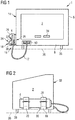
- FIG. 1 a vehicle data recording apparatus 1 having a vehicle data recording apparatus 2 and a data memory 4 configured as a so-called USB memory stick is shown.
- the data memory 4 is arranged outside a housing 6 of the vehicle data recording device 2.
- a device interface 10 is provided to a terminal of the data memory 4.
- the data memory 4 is connected to the device interface 10.
- the housing 6 On a housing outside 14, the housing 6 has a data storage 4 releasably supporting bracket 16.
- the holder 16 has two clamping elements 18, 20 which carry the data memory 4 in a clamping manner (see also FIGS FIG. 2 ) on.
- the clamping elements 18, 20 are in the front view (see FIG. 1 ) arranged one behind the other and formed identically; their education is based on the in the Front view of the front clamping element 18 briefly explained below:
- the clamping element 18 has a pressure force on the data memory 4 exercising spring tab 22.
- FIG. 1 recognizable that the clamping element 18 is U-shaped and the data memory 4 between the legs 24, 26 of the U is arranged.
- the spring tab 22 has a first leg 24 of the U, and the second leg 26 of the U is formed by the housing outer side 14, on which the holder 16 is arranged.
- the holder 16 has a securing element 28 designed as a clamping bracket in this exemplary embodiment, which prevents inadvertent release of the data memory 4.
- the holder 16 has a data storage 4 relative to the housing 6 supporting damping element 30.
- the housing 6 is approximately cuboid and has a front side 32, which faces a user and controls 34 has.
- the front side 32 is the outer wall 8, in which the device interface 10 is provided for connection of the data memory 4.
- the housing outer side 14, on which the holder 16 is arranged, is connected at an angle to the front side 32; in this embodiment, the angle is 90 °, the housing outer side 14 with the bracket 16 is a side surface of the approximately cuboidal housing. 6
- FIGS. 1, 2 with dashed line an upper side 36 of a dashboard of a motor vehicle, not shown, on which dashboard the vehicle data recording device 2 is constructed by means disposed on the housing 6 feet 38.
- the vehicle data recording device 2 is here a single device designed as a body unit.
Landscapes
- Physics & Mathematics (AREA)
- General Physics & Mathematics (AREA)
- Fittings On The Vehicle Exterior For Carrying Loads, And Devices For Holding Or Mounting Articles (AREA)
- Time Recorders, Dirve Recorders, Access Control (AREA)
Description
- Die Erfindung bezieht sich auf eine Fahrzeugdatenaufzeichnungsvorrichtung mit einem ein Gehäuse aufweisenden Fahrzeugdatenaufzeichnungsgerät und mit einem außerhalb des Gehäuses angeordneten Datenspeicher, wobei in einer Außenwandung des Gehäuses eine Geräteschnittstelle zu einem Anschluss des Datenspeichers vorgesehen ist und wobei der Datenspeicher mittels eines Verbindungskabels an die Geräteschnittstelle angeschlossen ist.
AusEP 2 037 420 A2 ist eine Fahrzeugdatenaufzeichnungsvorrichtung mit einem als digitaler Tachograph ausgebildeten Fahrzeugdatenaufzeichnungsgerät bekannt. Angeschlossen an eine an einer verschiedene Bedienelemente, namentlich einen Bildschirm, einen Karteneinführschacht und Tasten, aufweisenden Frontseite des Tachographen vorgesehene Steckerbuchse ist ein an einem Ende eines Kabels angeordneter elektrischer Anschlussstecker. Das andere Ende des Kabels ist ein loses, freies Ende, das einen Stecker zur Verbindung mit einem Übertragungssteuergerät aufweist. Neben anderen Elementen kann das Übertragungssteuergerät auch einen Speicher aufweisen. Um ein Überdecken der an der Frontseite des Tachographen angeordneten Bedienelemente zu vermeiden, ist das Kabel an der Frontseite mittels zweier Abzweigungen einer das Kabel abdeckenden Hülle befestigt. DieDE29505673 U1 offenbart ein Gerät zur Verarbeitung von elektrisch messbaren Zustandsgrößen in Kraftfahrzeugen mit einer Messwertaufnahmeeinheit und einer separaten Auswerteeinheit, wobei die Messwertaufnahmeeinheit und die Auswerteeinheit durch ein Kabel miteinander verbunden sind. Aus derUS 2010/0314521 ist eine Halterung für einen Fahrzeuginnenraum bekannt, um eines oder mehrere Objekte zu halten. DieDE 196 12 843 A1 offenbart ein Gehäuse mit Mitteln zur Befestigung auf einer Befestigungsplatte. Aufgabe der Erfindung ist es, eine Fahrzeugdatenaufzeichnungsvorrichtung der eingangs genannten Art mit einem Datenspeicher zu schaffen, welcher Datenspeicher einerseits fest und zuverlässig in der Fahrzeugdatenaufzeichnungsvorrichtung angeordnet ist, andererseits aber auch leicht aus der Vorrichtung entfernt werden kann. - Diese Aufgabe wird erfindungsgemäß gelöst mit einer Fahrzeugdatenaufzeichnungsvorrichtung nach dem unabhängigen Anspruch 1. Die erfindungsgemäße Fahrzeugdatenaufzeichnungsvorrichtung ist zur Anordnung und Verwendung in einem Kraftfahrzeug, insbesondere in einem Nutzkraftfahrzeug, vorgesehen. Bei dem Fahrzeugdatenaufzeichnungsgerät kann es sich insbesondere um einen Tachographen oder um ein auch unter der Bezeichnung On-Board Recorder bekanntes Aufzeichnungsgerät in einem Kraftfahrzeug handeln. Das Fahrzeugdatenaufzeichnungsgerät kann beispielsweise auch die Funktionen eines Mautgerätes umfassen. Kraftfahrzeuge, insbesondere auch Nutzkraftfahrzeuge, und in diesen angeordnete Geräte sind im Betrieb der Kraftfahrzeuge regelmäßig Schwingungen, insbesondere in Form von Vibrationen, ausgesetzt. Daher ist es bei der Erfindung von besonderem Vorteil, dass der Datenspeicher mit Hilfe der Halterung zuverlässig und sicher sowie fest getragen wird. Auch bei starken Verzögerungen, wie sie zum Beispiel bei einem scharfen Abbremsen des Kraftfahrzeugs auftreten können, wird der Datenspeicher sicher in der Halterung gehalten. Der Datenspeicher kann zum Beispiel zur Sicherung von mittels des Fahrzeugdatenaufzeichnungsgerätes aufgezeichneten Daten dienen. Besonders vorteilhaft ist es dabei, wenn der Datenspeicher nicht nur von der Halterung lösbar ist, beispielsweise um ihn zur Datenweitergabe leichter mit einem anderen Gerät verbinden zu können, sondern wenn der Datenspeicher zudem auch von dem Verbindungskabel trennbar ist. Ist der Datenspeicher ferner ein transportabler Datenspeicher, so kann er in einfacher Weise von einem Benutzer des Fahrzeugdatenaufzeichnungsgerätes beispielsweise zur sicheren Verwahrung der auf dem Datenspeicher vorhandenen Daten oder zum Überspielen dieser Daten auf einen stationären Computer aus dem Kraftfahrzeug mitgenommen werden. Vorzugsweise ist zwischen Datenspeicher und Verbindungskabel eine das Verbindungskabel mit dem Datenspeicher verbindende normierte Schnittstelle vorgesehen. Für eine freizügige Verbindbarkeit des Datenspeichers mit anderen Geräten als dem Fahrzeugdatenaufzeichnungsgerät, zum Beispiel mit stationären Computern, kann die normierte Schnittstelle insbesondere eine USB-Schnittstelle sein. Vorzugsweise handelt es sich bei dem Datenspeicher um einen sogenannten USB-Speicherstick. Die Außenwandung des Gehäuses des Fahrzeugdatenaufzeichnungsgerätes, in welcher die Geräteschnittstelle zum Anschluss des Datenspeichers vorgesehen ist, ist vorzugsweise eine einem Benutzer der Fahrzeugdatenaufzeichnungsvorrichtung zugewandte Frontseite des Gehäuses. Vorzugsweise ist das Verbindungskabel mittels einer Steckverbindung mit der Geräteschnittstelle verbunden. Das Verbindungskabel könnte grundsätzlich unlösbar, das heißt nicht beschädigungsfrei lösbar, mit dem Datenspeicher verbunden sein; vorzugsweise ist aber der Datenspeicher mit dem Verbindungskabel mittels einer Steckverbindung, welche Steckverbindung vorzugsweise die oben genannte normierte Schnittstelle aufweist, verbunden. Von besonderem Vorteil ist bei der Erfindung ferner eine mechanische Entkoppelung von Geräteschnittstelle und Datenspeicher aufgrund des zwischen diesen angeordneten Verbindungskabels. So führen Schwingungen des Datenspeichers nicht zu einer mechanischen Belastung der Geräteschnittstelle.
- Für eine besonders einfache Entnehmbarkeit des Datenspeichers aus der Fahrzeugdatenaufzeichnungsvorrichtung weist gemäß der Erfindung die Halterung zumindest ein den Datenspeicher klemmend tragendes Klemmelement auf. Besonders einfach im Aufbau und kostengünstig in der Herstellung kann das Gehäuse des Fahrzeugdatenaufzeichnungsgerätes sein, wenn gemäß einer vorteilhaften Weiterbildung der Erfindung das Klemmelement eine eine Druckkraft auf den Datenspeicher ausübende Federlasche aufweist. Die Druckkraft ist dabei eine Klemmkraft für den Datenspeicher. Die Federlasche kann beispielsweise aus Metall oder aus einem Kunststoff bestehen.
- Gemäß der Erfindung ist das Klemmelement U-förmig ausgebildet, und der Datenspeicher ist zwischen den Schenkeln des U angeordnet. Damit weist die Halterung bei einfacher konstruktiver Ausgestaltung eine besonders hohe Funktionssicherheit auf. Die Schenkel des U klemmen den Datenspeicher zwischen sich ein.
Vorteilhaft noch weiter vereinfacht kann der Aufbau der Halterung werden, wenn gemäß einer Weiterbildung der Erfindung die Federlasche einen ersten Schenkel des U aufweist und wenn der zweite Schenkel des U von der Gehäuseaußenseite gebildet wird.
Insbesondere bei einer Fahrzeugdatenaufzeichnungsvorrichtung in einem in unebenem Gelände eingesetzten Kraftfahrzeug, zum Beispiel einem Baustellenlastkraftwagen oder einem Geländelastkraftwagen, oder beispielsweise bei einer regelmäßig besonders starker Vibrationsbeanspruchung ausgesetzten Fahrzeugdatenaufzeichnungsvorrichtung ist es sehr vorteilhaft, wenn gemäß einer anderen Weiterbildung der Erfindung die Halterung ein ein unbeabsichtigtes Lösen des Datenspeichers verhinderndes Sicherungselement aufweist. Das Sicherungselement kann zum Beispiel einen Klemmbügel oder eine Gummilasche aufweisen. Auch kann das Sicherungselement für ein besonders einfaches Öffnen und Schließen des Sicherungselementes beispielsweise einen sogenannten Klettverschluss aufweisen.
Der Schutz des Datenspeichers zum Beispiel auch bei einer starken Vibrations- oder Schwingungsbelastung der erfindungsgemäßen Fahrzeugdatenaufzeichnungsvorrichtung ist vorteilhaft zusätzlich verbessert, wenn gemäß einer anderen Weiterbildung der Erfindung die Halterung ein den Datenspeicher gegenüber dem Gehäuse abstützendes Dämpfungselement aufweist. Das Dämpfungselement kann zum Beispiel ein Polsterelement sein. Es kann einteilig oder mehrteilig ausgebildet sein. Das Dämpfungselement kann beispielsweise an der dem Datenspeicher zugewandten Innenseite eines oder beider Schenkel des U des U-förmig ausgebildeten Klemmelementes angeordnet sein; alternativ oder zusätzlich kann das Dämpfungselement auch an der dem Datenspeicher zugewandten Innenseite der zwischen den beiden Schenkeln angeordneten Senke des U angeordnet sein.
Man könnte sich vorstellen, dass das Gehäuse des Fahrzeugdatenaufzeichnungsgerätes an einer Frontseite des Gehäuses die den Datenspeicher tragende Halterung aufweist. Jedoch wird vorteilhaft die Zugänglichkeit des Fahrzeugdatenaufzeichnungsgerätes und insbesondere von Bedienelementen an der Frontseite des Fahrzeugdatenaufzeichnungsgerätes nicht eingeschränkt, wenn gemäß einer anderen Weiterbildung der Erfindung das Gehäuse eine einem Benutzer zugewandte Frontseite aufweist und wenn die Halterung an einer unter einem Winkel mit der Frontseite verbundenen Gehäuseaußenseite angeordnet ist. Bevorzugt ist das Gehäuse zumindest im wesentlichen quaderförmig ausgebildet. Vorzugsweise ist die Gehäuseaußenseite, an welcher die Halterung angeordnet ist, unter einem zumindest im wesentlichen rechten Winkel mit der Frontseite verbunden und liegt bezogen auf den Benutzer neben und hinter der Frontseite.
Einer anderen vorteilhaften Weiterbildung der Erfindung gemäß ist das Fahrzeugdatenaufzeichnungsgerät ein Einzelgerät. Damit kann das Gehäuse die Halterung für den Datenspeicher in einfacher Weise an besonders gut zugänglicher Stelle aufweisen. Einzelgerät bedeutet, dass das Fahrzeugdatenaufzeichnungsgerät kein Einbaugerät zum Einbau in eine Armaturentafel oder ein Cockpit des Kraftfahrzeugs ist; damit ist auch ein Einbaurahmen für eine solche Montage des Fahrzeugdatenaufzeichnungsgerätes nicht erforderlich. Im Gegensatz zu einem Einbaugerät ist das Fahrzeugdatenaufzeichnungsgerät als erfindungsgemäß weitergebildetes Einzelgerät vorzugsweise ein Aufbaugerät oder gegebenenfalls ein Anbau- oder Unterbaugerät. Als Aufbaugerät kann das Fahrzeugdatenaufzeichnungsgerät beispielsweise auf eine Armaturentafel des Kraftfahrzeugs aufgesetzt und dort montiert werden, als Unterbaugerät kann es zum Beispiel unter einem Dachhimmel einer Fahrerkabine oder eines Fahrgastraumes des Kraftfahrzeuges hängend montiert werden. - Ein Ausführungsbeispiel der Erfindung ist in der Zeichnung dargestellt und wird im Folgenden näher beschrieben. Es zeigen in schematisierter, skizzenhafter Darstellung:
- Figur 1
- eine Fahrzeugdatenaufzeichnungsvorrichtung in einer Vorderansicht und
- Figur 2
- die Fahrzeugdatenaufzeichnungsvorrichtung aus Figur 1 in einer Seitenansicht.
- Sich entsprechende Elemente sind in allen Figuren mit jeweils gleichen Bezugszeichen versehen.
- In
Figur 1 ist eine Fahrzeugdatenaufzeichnungsvorrichtung 1 mit einem Fahrzeugdatenaufzeichnungsgerät 2 und einem als sogenannter USB-Speicherstick ausgebildeten Datenspeicher 4 gezeigt. Der Datenspeicher 4 ist außerhalb eines Gehäuses 6 des Fahrzeugdatenaufzeichnungsgerätes 2 angeordnet. In einer frontseitigen Außenwandung 8 des Gehäuses 6 ist eine Geräteschnittstelle 10 zu einem Anschluss des Datenspeichers 4 vorgesehen. Mittels eines Verbindungskabels 12 ist der Datenspeicher 4 an die Geräteschnittstelle 10 angeschlossen. An einer Gehäuseaußenseite 14 weist das Gehäuse 6 eine den Datenspeicher 4 lösbar tragende Halterung 16 auf. - Die Halterung 16 weist in diesem Ausführungsbeispiel zwei den Datenspeicher 4 klemmend tragende Klemmelemente 18, 20 (siehe auch
Figur 2 ) auf. Die Klemmelemente 18, 20 sind in der Ansicht von vorne (sieheFigur 1 ) hintereinander angeordnet und identisch ausgebildet; ihre Ausbildung wird anhand des in der Ansicht von vorne vorderen Klemmelementes 18 nachfolgend kurz erläutert: Das Klemmelement 18 weist eine eine Druckkraft auf den Datenspeicher 4 ausübende Federlasche 22 auf. Ferner ist inFigur 1 erkennbar, dass das Klemmelement 18 U-förmig ausgebildet und der Datenspeicher 4 zwischen den Schenkeln 24, 26 des U angeordnet ist. Dabei weist die Federlasche 22 einen ersten Schenkel 24 des U auf, und der zweite Schenkel 26 des U wird von der Gehäuseaußenseite 14, an welcher die Halterung 16 angeordnet ist, gebildet. - Weiterhin weist die Halterung 16 ein in diesem Ausführungsbeispiel als Klemmbügel ausgebildetes Sicherungselement 28 auf, welches ein unbeabsichtigtes Lösen des Datenspeichers 4 verhindert. Darüber hinaus weist die Halterung 16 ein den Datenspeicher 4 gegenüber dem Gehäuse 6 abstützendes Dämpfungselement 30 auf.
- Aus
Figuren 1, 2 ist erkennbar, dass das Gehäuse 6 in etwa quaderförmig ausgebildet ist und eine Frontseite 32 aufweist, welche einem Benutzer zugewandt ist und Bedienelemente 34 aufweist. In diesem Beispiel ist die Frontseite 32 die Außenwandung 8, in welcher die Geräteschnittstelle 10 zum Anschluss des Datenspeichers 4 vorgesehen ist. Die Gehäuseaußenseite 14, an der die Halterung 16 angeordnet ist, ist unter einem Winkel mit der Frontseite 32 verbunden; in diesem Ausführungsbeispiel beträgt der Winkel 90°, die Gehäuseaußenseite 14 mit der Halterung 16 ist eine Seitenfläche des in etwa quaderförmigen Gehäuses 6. - Weiterhin ist in
Figuren 1, 2 mit gestrichelter Linie eine Oberseite 36 einer nicht weiter dargestellten Armaturentafel eines Kraftfahrzeuges gezeigt, auf welche Armaturentafel das Fahrzeugdatenaufzeichnungsgerät 2 mittels an dem Gehäuse 6 angeordneten Füßen 38 aufgebaut ist. Das Fahrzeugdatenaufzeichnungsgerät 2 ist hier ein als Aufbaugerät ausgebildetes Einzelgerät.
Claims (7)
- Fahrzeugdatenaufzeichnungsvorrichtung mit einem ein Gehäuse aufweisenden Fahrzeugdatenaufzeichnungsgerät und mit einem außerhalb des Gehäuses angeordneten Datenspeicher, wobei in einer Außenwandung des Gehäuses eine Geräteschnittstelle zu einem Anschluss des Datenspeichers vorgesehen ist und wobei der Datenspeicher mittels eines Verbindungskabels an die Geräteschnittstelle angeschlossen ist, dadurch gekennzeichnet, dass das Gehäuse (6) an einer Gehäuseaußenseite (14) eine den Datenspeicher (4) lösbar tragende Halterung (16) aufweist, dass die Halterung (16) zumindest ein den Datenspeicher (4) klemmend tragendes Klemmelement (18) aufweist und dass das Klemmelement (18) U-förmig ausgebildet ist und dass der Datenspeicher (4) zwischen den Schenkeln (24, 26) des U angeordnet ist, so dass die Schenkel (24, 26) des U den Datenspeicher (4) zwischen sich einklemmen.
- Fahrzeugdatenaufzeichnungsvorrichtung nach Anspruch 1, dadurch gekennzeichnet, dass das Klemmelement (18) eine eine Druckkraft auf den Datenspeicher (4) ausübende Federlasche (22) aufweist.
- Fahrzeugdatenaufzeichnungsvorrichtung nach Anspruch 2, dadurch gekennzeichnet, dass die Federlasche (22) einen ersten Schenkel (24) des U aufweist und dass der zweite Schenkel (26) des U von der Gehäuseaußenseite (14) gebildet wird.
- Fahrzeugdatenaufzeichnungsvorrichtung nach einem der vorhergehenden Ansprüche, dadurch gekennzeichnet, dass die Halterung (16) ein ein unbeabsichtigtes Lösen des Datenspeichers (4) verhinderndes Sicherungselement (28) aufweist.
- Fahrzeugdatenaufzeichnungsvorrichtung nach einem der vorhergehenden Ansprüche, dadurch gekennzeichnet, dass die Halterung (16) ein den Datenspeicher (4) gegenüber dem Gehäuse (6) abstützendes Dämpfungselement (30) aufweist.
- Fahrzeugdatenaufzeichnungsvorrichtung nach einem der vorhergehenden Ansprüche, dadurch gekennzeichnet, dass das Gehäuse (6) eine einem Benutzer zugewandte Frontseite (32) aufweist und dass die Halterung (16) an einer unter einem Winkel mit der Frontseite (32) verbundenen Gehäuseaußenseite (14) angeordnet ist.
- Fahrzeugdatenaufzeichnungsvorrichtung nach einem der vorhergehenden Ansprüche, dadurch gekennzeichnet, dass das Fahrzeugdatenaufzeichnungsgerät (2) ein Einzelgerät ist.
Applications Claiming Priority (1)
| Application Number | Priority Date | Filing Date | Title |
|---|---|---|---|
| DE102011014978A DE102011014978A1 (de) | 2011-03-24 | 2011-03-24 | Fahrzeugdatenaufzeichnungsvorrichtung |
Publications (3)
| Publication Number | Publication Date |
|---|---|
| EP2503517A2 EP2503517A2 (de) | 2012-09-26 |
| EP2503517A3 EP2503517A3 (de) | 2016-11-09 |
| EP2503517B1 true EP2503517B1 (de) | 2018-05-16 |
Family
ID=45811341
Family Applications (1)
| Application Number | Title | Priority Date | Filing Date |
|---|---|---|---|
| EP12158194.6A Not-in-force EP2503517B1 (de) | 2011-03-24 | 2012-03-06 | Fahrzeugdatenaufzeichnungsvorrichtung |
Country Status (3)
| Country | Link |
|---|---|
| US (1) | US20120245757A1 (de) |
| EP (1) | EP2503517B1 (de) |
| DE (1) | DE102011014978A1 (de) |
Families Citing this family (2)
| Publication number | Priority date | Publication date | Assignee | Title |
|---|---|---|---|---|
| DE102008061710A1 (de) * | 2008-12-12 | 2010-06-17 | Continental Automotive Gmbh | Verfahren zum Betreiben einer Sensorvorrichtung und Sensorvorrichtung |
| US20130335567A1 (en) * | 2012-06-18 | 2013-12-19 | Wen Chuan Wang | Vehicle event data recorder set capable of retaining a handset |
Family Cites Families (16)
| Publication number | Priority date | Publication date | Assignee | Title |
|---|---|---|---|---|
| US5222132A (en) * | 1992-03-13 | 1993-06-22 | Rioux Jr Robert A | Support bracket for telephone |
| US5305381A (en) * | 1992-11-09 | 1994-04-19 | Wang Chin Y | Cradle for telephone |
| US5480115A (en) * | 1994-06-20 | 1996-01-02 | Haltof; Garry P. | Hand release bracket |
| DE29505673U1 (de) * | 1995-04-01 | 1995-06-08 | IBIS GmbH, 44225 Dortmund | Gerät zur Verarbeitung von elektrisch meßbaren Zustandsgrößen in Kraftfahrzeugen |
| DE19612843A1 (de) * | 1996-03-30 | 1997-10-02 | Telefunken Microelectron | Gehäuse mit Mittel zur Befestigung auf einer Befestigungsplatte |
| US6491194B2 (en) * | 2001-01-29 | 2002-12-10 | Ernest Marvin | Cell phone holder for motor vehicles |
| US20030081122A1 (en) * | 2001-10-30 | 2003-05-01 | Kirmuss Charles Bruno | Transmitter-based mobile video locating |
| US7477919B2 (en) * | 2002-09-19 | 2009-01-13 | Peter Warren | Handheld input/output device providing enhanced user interface for a mobile telephone |
| US20050170699A1 (en) * | 2004-02-03 | 2005-08-04 | Overtoom Eric J. | USB OTG adapter module for debugging USB OTG devices |
| DE102004030869A1 (de) * | 2004-06-25 | 2006-01-19 | Siemens Ag | Datenübertragung in einer Anordnung mit einem Tachographen |
| US7522069B2 (en) * | 2006-07-27 | 2009-04-21 | Vmatter Holdings, Llc | Vehicle trip logger |
| WO2008022466A1 (en) * | 2006-08-25 | 2008-02-28 | March Networks Corporation | Mobile event data recorder with multiple orientation vibration isolation |
| DE602007003804D1 (de) * | 2007-03-23 | 2010-01-28 | Bury Sp Zoo | Fahrzeughalterung für ein Mobiltelefon |
| ITTO20070647A1 (it) | 2007-09-14 | 2009-03-15 | Actia Italia S R L | Dispositivo di connessione per il trasferimento di dati registrati da un tachigrafo digitale |
| EP2080672B1 (de) * | 2008-01-20 | 2012-10-03 | BURY Sp. z o.o. | Mobiltelefonhalter mit seitlichen Anschlüssen, insbesondere für ein Fahrzeug |
| US8303016B2 (en) * | 2009-06-11 | 2012-11-06 | Ford Global Technologies, Llc | Flexible arm stowage retainer for vehicle |
-
2011
- 2011-03-24 DE DE102011014978A patent/DE102011014978A1/de not_active Ceased
-
2012
- 2012-03-06 EP EP12158194.6A patent/EP2503517B1/de not_active Not-in-force
- 2012-03-23 US US13/429,009 patent/US20120245757A1/en not_active Abandoned
Also Published As
| Publication number | Publication date |
|---|---|
| US20120245757A1 (en) | 2012-09-27 |
| EP2503517A3 (de) | 2016-11-09 |
| EP2503517A2 (de) | 2012-09-26 |
| DE102011014978A1 (de) | 2012-09-27 |
Similar Documents
| Publication | Publication Date | Title |
|---|---|---|
| EP3383709B1 (de) | Kabelführungseinrichtung für anschlusskabel eines gassackmoduls, verkabelung, gassackmodul sowie lenkrad oder fahrzeug mit einer derartigen kabelführungseinrichtung | |
| DE102014117694A1 (de) | Mobiltelefonhalter für ein Fahrzeug | |
| DE102016216299A1 (de) | Elektroanschlusskasten und Kabelbaum | |
| EP2503517B1 (de) | Fahrzeugdatenaufzeichnungsvorrichtung | |
| DE202008004580U1 (de) | Vorrichtung zur Aufnahme eines mobilen Endgerätes | |
| DE202010003686U1 (de) | Anhängerkupplung | |
| WO2012159961A1 (de) | Strukturelement für eine steckeinheit zum anschluss elektrischer bauteile und steckeinheit für ein fahrzeug, insbesondere ein schienenfahrzeug | |
| DE10037089C2 (de) | Befestigungsanordnung für eine flache Schaltanordnung | |
| DE10043023A1 (de) | Sicherungsvorrichtung zum Schutz des Aufhebens einer elektrischen Verbindung durch einen Nichtberechtigten | |
| DE102013220476A1 (de) | Haltevorrichtung für ein Mobiltelefon in einem Fahrzeug | |
| DE19856314B4 (de) | Aufnahmevorrichtung für elektrische Geräte in Kraftfahrzeugen | |
| DE102017103842A1 (de) | Ladestecker mit einem gehäuse und einem zu dem gehäuse anpassbaren griffabschnitt | |
| DE102010029374A1 (de) | Leistungselektronikanordnung | |
| DE102021123068B4 (de) | Kabelbefestigungsvorrichtung mit Kugelgelenkverbindung; Kabelbaum sowie elektrische Antriebseinheit | |
| DE102010024341A1 (de) | Verbindungsvorrichtung und Verteilerschrank-Anordnung | |
| DE102010035577A1 (de) | Elektronikteilaufnahmebox | |
| DE102016219421A1 (de) | Gehäuse mit Zugentlastung für ein Kabel | |
| DE102019128976A1 (de) | Motorrad | |
| DE102009049629A1 (de) | Vorrichtung zur Sicherung einer im Innenraum eines Fahrzeuges mobilen, insbesondere lösbar anordbaren Komponente | |
| DE102016007781A1 (de) | Instrumententräger eines Kraftfahrzeugs sowie Kraftfahrzeug | |
| DE102014117468A1 (de) | Steuersystem für mindestens eine elektrische Komponente eines Fahrrades und Fahrrad mit einem derartigen Steuersystem | |
| DE102009050168B4 (de) | Vorrichtung zur Befestigung von Kabeln oder dergleichen | |
| DE102012203727A1 (de) | Kabelanordnung an einem Wandelement eines Fahrzeugs | |
| EP2268511B1 (de) | Vorrichtung zum betätigen von schlössern, insbesondere an fahrzeugen | |
| DE102009048158A1 (de) | Anordnung zum Halten von elektrischen Geräten, insbesondere eines Navigationsgeräts innerhalb eines Fahrzeugs |
Legal Events
| Date | Code | Title | Description |
|---|---|---|---|
| PUAI | Public reference made under article 153(3) epc to a published international application that has entered the european phase |
Free format text: ORIGINAL CODE: 0009012 |
|
| AK | Designated contracting states |
Kind code of ref document: A2 Designated state(s): AL AT BE BG CH CY CZ DE DK EE ES FI FR GB GR HR HU IE IS IT LI LT LU LV MC MK MT NL NO PL PT RO RS SE SI SK SM TR |
|
| AX | Request for extension of the european patent |
Extension state: BA ME |
|
| PUAL | Search report despatched |
Free format text: ORIGINAL CODE: 0009013 |
|
| AK | Designated contracting states |
Kind code of ref document: A3 Designated state(s): AL AT BE BG CH CY CZ DE DK EE ES FI FR GB GR HR HU IE IS IT LI LT LU LV MC MK MT NL NO PL PT RO RS SE SI SK SM TR |
|
| AX | Request for extension of the european patent |
Extension state: BA ME |
|
| RIC1 | Information provided on ipc code assigned before grant |
Ipc: G07C 7/00 20060101AFI20161003BHEP Ipc: G07C 5/08 20060101ALI20161003BHEP |
|
| STAA | Information on the status of an ep patent application or granted ep patent |
Free format text: STATUS: REQUEST FOR EXAMINATION WAS MADE |
|
| 17P | Request for examination filed |
Effective date: 20170509 |
|
| RBV | Designated contracting states (corrected) |
Designated state(s): AL AT BE BG CH CY CZ DE DK EE ES FI FR GB GR HR HU IE IS IT LI LT LU LV MC MK MT NL NO PL PT RO RS SE SI SK SM TR |
|
| GRAP | Despatch of communication of intention to grant a patent |
Free format text: ORIGINAL CODE: EPIDOSNIGR1 |
|
| STAA | Information on the status of an ep patent application or granted ep patent |
Free format text: STATUS: GRANT OF PATENT IS INTENDED |
|
| INTG | Intention to grant announced |
Effective date: 20171215 |
|
| GRAS | Grant fee paid |
Free format text: ORIGINAL CODE: EPIDOSNIGR3 |
|
| GRAA | (expected) grant |
Free format text: ORIGINAL CODE: 0009210 |
|
| STAA | Information on the status of an ep patent application or granted ep patent |
Free format text: STATUS: THE PATENT HAS BEEN GRANTED |
|
| AK | Designated contracting states |
Kind code of ref document: B1 Designated state(s): AL AT BE BG CH CY CZ DE DK EE ES FI FR GB GR HR HU IE IS IT LI LT LU LV MC MK MT NL NO PL PT RO RS SE SI SK SM TR |
|
| REG | Reference to a national code |
Ref country code: GB Ref legal event code: FG4D Free format text: NOT ENGLISH |
|
| REG | Reference to a national code |
Ref country code: CH Ref legal event code: EP |
|
| REG | Reference to a national code |
Ref country code: IE Ref legal event code: FG4D Free format text: LANGUAGE OF EP DOCUMENT: GERMAN |
|
| REG | Reference to a national code |
Ref country code: AT Ref legal event code: REF Ref document number: 1000236 Country of ref document: AT Kind code of ref document: T Effective date: 20180615 |
|
| REG | Reference to a national code |
Ref country code: DE Ref legal event code: R096 Ref document number: 502012012695 Country of ref document: DE |
|
| REG | Reference to a national code |
Ref country code: NL Ref legal event code: MP Effective date: 20180516 |
|
| REG | Reference to a national code |
Ref country code: LT Ref legal event code: MG4D |
|
| PG25 | Lapsed in a contracting state [announced via postgrant information from national office to epo] |
Ref country code: NO Free format text: LAPSE BECAUSE OF FAILURE TO SUBMIT A TRANSLATION OF THE DESCRIPTION OR TO PAY THE FEE WITHIN THE PRESCRIBED TIME-LIMIT Effective date: 20180816 Ref country code: FI Free format text: LAPSE BECAUSE OF FAILURE TO SUBMIT A TRANSLATION OF THE DESCRIPTION OR TO PAY THE FEE WITHIN THE PRESCRIBED TIME-LIMIT Effective date: 20180516 Ref country code: LT Free format text: LAPSE BECAUSE OF FAILURE TO SUBMIT A TRANSLATION OF THE DESCRIPTION OR TO PAY THE FEE WITHIN THE PRESCRIBED TIME-LIMIT Effective date: 20180516 Ref country code: BG Free format text: LAPSE BECAUSE OF FAILURE TO SUBMIT A TRANSLATION OF THE DESCRIPTION OR TO PAY THE FEE WITHIN THE PRESCRIBED TIME-LIMIT Effective date: 20180816 Ref country code: SE Free format text: LAPSE BECAUSE OF FAILURE TO SUBMIT A TRANSLATION OF THE DESCRIPTION OR TO PAY THE FEE WITHIN THE PRESCRIBED TIME-LIMIT Effective date: 20180516 Ref country code: ES Free format text: LAPSE BECAUSE OF FAILURE TO SUBMIT A TRANSLATION OF THE DESCRIPTION OR TO PAY THE FEE WITHIN THE PRESCRIBED TIME-LIMIT Effective date: 20180516 |
|
| PG25 | Lapsed in a contracting state [announced via postgrant information from national office to epo] |
Ref country code: RS Free format text: LAPSE BECAUSE OF FAILURE TO SUBMIT A TRANSLATION OF THE DESCRIPTION OR TO PAY THE FEE WITHIN THE PRESCRIBED TIME-LIMIT Effective date: 20180516 Ref country code: NL Free format text: LAPSE BECAUSE OF FAILURE TO SUBMIT A TRANSLATION OF THE DESCRIPTION OR TO PAY THE FEE WITHIN THE PRESCRIBED TIME-LIMIT Effective date: 20180516 Ref country code: GR Free format text: LAPSE BECAUSE OF FAILURE TO SUBMIT A TRANSLATION OF THE DESCRIPTION OR TO PAY THE FEE WITHIN THE PRESCRIBED TIME-LIMIT Effective date: 20180817 Ref country code: HR Free format text: LAPSE BECAUSE OF FAILURE TO SUBMIT A TRANSLATION OF THE DESCRIPTION OR TO PAY THE FEE WITHIN THE PRESCRIBED TIME-LIMIT Effective date: 20180516 Ref country code: LV Free format text: LAPSE BECAUSE OF FAILURE TO SUBMIT A TRANSLATION OF THE DESCRIPTION OR TO PAY THE FEE WITHIN THE PRESCRIBED TIME-LIMIT Effective date: 20180516 |
|
| PG25 | Lapsed in a contracting state [announced via postgrant information from national office to epo] |
Ref country code: PL Free format text: LAPSE BECAUSE OF FAILURE TO SUBMIT A TRANSLATION OF THE DESCRIPTION OR TO PAY THE FEE WITHIN THE PRESCRIBED TIME-LIMIT Effective date: 20180516 Ref country code: EE Free format text: LAPSE BECAUSE OF FAILURE TO SUBMIT A TRANSLATION OF THE DESCRIPTION OR TO PAY THE FEE WITHIN THE PRESCRIBED TIME-LIMIT Effective date: 20180516 Ref country code: DK Free format text: LAPSE BECAUSE OF FAILURE TO SUBMIT A TRANSLATION OF THE DESCRIPTION OR TO PAY THE FEE WITHIN THE PRESCRIBED TIME-LIMIT Effective date: 20180516 Ref country code: CZ Free format text: LAPSE BECAUSE OF FAILURE TO SUBMIT A TRANSLATION OF THE DESCRIPTION OR TO PAY THE FEE WITHIN THE PRESCRIBED TIME-LIMIT Effective date: 20180516 Ref country code: RO Free format text: LAPSE BECAUSE OF FAILURE TO SUBMIT A TRANSLATION OF THE DESCRIPTION OR TO PAY THE FEE WITHIN THE PRESCRIBED TIME-LIMIT Effective date: 20180516 Ref country code: SK Free format text: LAPSE BECAUSE OF FAILURE TO SUBMIT A TRANSLATION OF THE DESCRIPTION OR TO PAY THE FEE WITHIN THE PRESCRIBED TIME-LIMIT Effective date: 20180516 |
|
| REG | Reference to a national code |
Ref country code: DE Ref legal event code: R097 Ref document number: 502012012695 Country of ref document: DE |
|
| PG25 | Lapsed in a contracting state [announced via postgrant information from national office to epo] |
Ref country code: SM Free format text: LAPSE BECAUSE OF FAILURE TO SUBMIT A TRANSLATION OF THE DESCRIPTION OR TO PAY THE FEE WITHIN THE PRESCRIBED TIME-LIMIT Effective date: 20180516 Ref country code: IT Free format text: LAPSE BECAUSE OF FAILURE TO SUBMIT A TRANSLATION OF THE DESCRIPTION OR TO PAY THE FEE WITHIN THE PRESCRIBED TIME-LIMIT Effective date: 20180516 |
|
| PLBE | No opposition filed within time limit |
Free format text: ORIGINAL CODE: 0009261 |
|
| STAA | Information on the status of an ep patent application or granted ep patent |
Free format text: STATUS: NO OPPOSITION FILED WITHIN TIME LIMIT |
|
| 26N | No opposition filed |
Effective date: 20190219 |
|
| PG25 | Lapsed in a contracting state [announced via postgrant information from national office to epo] |
Ref country code: SI Free format text: LAPSE BECAUSE OF FAILURE TO SUBMIT A TRANSLATION OF THE DESCRIPTION OR TO PAY THE FEE WITHIN THE PRESCRIBED TIME-LIMIT Effective date: 20180516 |
|
| PG25 | Lapsed in a contracting state [announced via postgrant information from national office to epo] |
Ref country code: MC Free format text: LAPSE BECAUSE OF FAILURE TO SUBMIT A TRANSLATION OF THE DESCRIPTION OR TO PAY THE FEE WITHIN THE PRESCRIBED TIME-LIMIT Effective date: 20180516 |
|
| REG | Reference to a national code |
Ref country code: CH Ref legal event code: PL |
|
| GBPC | Gb: european patent ceased through non-payment of renewal fee |
Effective date: 20190306 |
|
| PG25 | Lapsed in a contracting state [announced via postgrant information from national office to epo] |
Ref country code: AL Free format text: LAPSE BECAUSE OF FAILURE TO SUBMIT A TRANSLATION OF THE DESCRIPTION OR TO PAY THE FEE WITHIN THE PRESCRIBED TIME-LIMIT Effective date: 20180516 Ref country code: LU Free format text: LAPSE BECAUSE OF NON-PAYMENT OF DUE FEES Effective date: 20190306 |
|
| REG | Reference to a national code |
Ref country code: BE Ref legal event code: MM Effective date: 20190331 |
|
| PG25 | Lapsed in a contracting state [announced via postgrant information from national office to epo] |
Ref country code: LI Free format text: LAPSE BECAUSE OF NON-PAYMENT OF DUE FEES Effective date: 20190331 Ref country code: IE Free format text: LAPSE BECAUSE OF NON-PAYMENT OF DUE FEES Effective date: 20190306 Ref country code: CH Free format text: LAPSE BECAUSE OF NON-PAYMENT OF DUE FEES Effective date: 20190331 Ref country code: GB Free format text: LAPSE BECAUSE OF NON-PAYMENT OF DUE FEES Effective date: 20190306 |
|
| PG25 | Lapsed in a contracting state [announced via postgrant information from national office to epo] |
Ref country code: FR Free format text: LAPSE BECAUSE OF NON-PAYMENT OF DUE FEES Effective date: 20190331 Ref country code: BE Free format text: LAPSE BECAUSE OF NON-PAYMENT OF DUE FEES Effective date: 20190331 |
|
| PG25 | Lapsed in a contracting state [announced via postgrant information from national office to epo] |
Ref country code: TR Free format text: LAPSE BECAUSE OF FAILURE TO SUBMIT A TRANSLATION OF THE DESCRIPTION OR TO PAY THE FEE WITHIN THE PRESCRIBED TIME-LIMIT Effective date: 20180516 |
|
| PG25 | Lapsed in a contracting state [announced via postgrant information from national office to epo] |
Ref country code: PT Free format text: LAPSE BECAUSE OF FAILURE TO SUBMIT A TRANSLATION OF THE DESCRIPTION OR TO PAY THE FEE WITHIN THE PRESCRIBED TIME-LIMIT Effective date: 20180917 Ref country code: MT Free format text: LAPSE BECAUSE OF FAILURE TO SUBMIT A TRANSLATION OF THE DESCRIPTION OR TO PAY THE FEE WITHIN THE PRESCRIBED TIME-LIMIT Effective date: 20180516 |
|
| REG | Reference to a national code |
Ref country code: AT Ref legal event code: MM01 Ref document number: 1000236 Country of ref document: AT Kind code of ref document: T Effective date: 20190306 |
|
| PG25 | Lapsed in a contracting state [announced via postgrant information from national office to epo] |
Ref country code: AT Free format text: LAPSE BECAUSE OF NON-PAYMENT OF DUE FEES Effective date: 20190306 |
|
| PG25 | Lapsed in a contracting state [announced via postgrant information from national office to epo] |
Ref country code: CY Free format text: LAPSE BECAUSE OF FAILURE TO SUBMIT A TRANSLATION OF THE DESCRIPTION OR TO PAY THE FEE WITHIN THE PRESCRIBED TIME-LIMIT Effective date: 20180516 |
|
| PG25 | Lapsed in a contracting state [announced via postgrant information from national office to epo] |
Ref country code: IS Free format text: LAPSE BECAUSE OF FAILURE TO SUBMIT A TRANSLATION OF THE DESCRIPTION OR TO PAY THE FEE WITHIN THE PRESCRIBED TIME-LIMIT Effective date: 20180916 |
|
| PG25 | Lapsed in a contracting state [announced via postgrant information from national office to epo] |
Ref country code: HU Free format text: LAPSE BECAUSE OF FAILURE TO SUBMIT A TRANSLATION OF THE DESCRIPTION OR TO PAY THE FEE WITHIN THE PRESCRIBED TIME-LIMIT; INVALID AB INITIO Effective date: 20120306 |
|
| PG25 | Lapsed in a contracting state [announced via postgrant information from national office to epo] |
Ref country code: MK Free format text: LAPSE BECAUSE OF FAILURE TO SUBMIT A TRANSLATION OF THE DESCRIPTION OR TO PAY THE FEE WITHIN THE PRESCRIBED TIME-LIMIT Effective date: 20180516 |
|
| REG | Reference to a national code |
Ref country code: DE Ref legal event code: R081 Ref document number: 502012012695 Country of ref document: DE Owner name: CONTINENTAL AUTOMOTIVE TECHNOLOGIES GMBH, DE Free format text: FORMER OWNER: CONTINENTAL AUTOMOTIVE GMBH, 30165 HANNOVER, DE |
|
| P01 | Opt-out of the competence of the unified patent court (upc) registered |
Effective date: 20230522 |
|
| REG | Reference to a national code |
Ref country code: DE Ref legal event code: R081 Ref document number: 502012012695 Country of ref document: DE Owner name: CONTINENTAL AUTOMOTIVE TECHNOLOGIES GMBH, DE Free format text: FORMER OWNER: CONTINENTAL AUTOMOTIVE TECHNOLOGIES GMBH, 30165 HANNOVER, DE |
|
| PGFP | Annual fee paid to national office [announced via postgrant information from national office to epo] |
Ref country code: DE Payment date: 20240331 Year of fee payment: 13 |
|
| REG | Reference to a national code |
Ref country code: DE Ref legal event code: R119 Ref document number: 502012012695 Country of ref document: DE |
|
| PG25 | Lapsed in a contracting state [announced via postgrant information from national office to epo] |
Ref country code: DE Free format text: LAPSE BECAUSE OF NON-PAYMENT OF DUE FEES Effective date: 20251001 |