EP3355416A1 - Elektrische steckverbindung zwischen einer stromquelle und einem elektrischen arbeitsgerät - Google Patents
Elektrische steckverbindung zwischen einer stromquelle und einem elektrischen arbeitsgerät Download PDFInfo
- Publication number
- EP3355416A1 EP3355416A1 EP18153488.4A EP18153488A EP3355416A1 EP 3355416 A1 EP3355416 A1 EP 3355416A1 EP 18153488 A EP18153488 A EP 18153488A EP 3355416 A1 EP3355416 A1 EP 3355416A1
- Authority
- EP
- European Patent Office
- Prior art keywords
- plug
- contact
- connection according
- electrical
- socket
- Prior art date
- Legal status (The legal status is an assumption and is not a legal conclusion. Google has not performed a legal analysis and makes no representation as to the accuracy of the status listed.)
- Granted
Links
Images





Classifications
-
- H—ELECTRICITY
- H01—ELECTRIC ELEMENTS
- H01R—ELECTRICALLY-CONDUCTIVE CONNECTIONS; STRUCTURAL ASSOCIATIONS OF A PLURALITY OF MUTUALLY-INSULATED ELECTRICAL CONNECTING ELEMENTS; COUPLING DEVICES; CURRENT COLLECTORS
- H01R24/00—Two-part coupling devices, or either of their cooperating parts, characterised by their overall structure
- H01R24/38—Two-part coupling devices, or either of their cooperating parts, characterised by their overall structure having concentrically or coaxially arranged contacts
-
- H—ELECTRICITY
- H01—ELECTRIC ELEMENTS
- H01R—ELECTRICALLY-CONDUCTIVE CONNECTIONS; STRUCTURAL ASSOCIATIONS OF A PLURALITY OF MUTUALLY-INSULATED ELECTRICAL CONNECTING ELEMENTS; COUPLING DEVICES; CURRENT COLLECTORS
- H01R13/00—Details of coupling devices of the kinds covered by groups H01R12/70 or H01R24/00 - H01R33/00
- H01R13/02—Contact members
- H01R13/04—Pins or blades for co-operation with sockets
-
- H—ELECTRICITY
- H01—ELECTRIC ELEMENTS
- H01R—ELECTRICALLY-CONDUCTIVE CONNECTIONS; STRUCTURAL ASSOCIATIONS OF A PLURALITY OF MUTUALLY-INSULATED ELECTRICAL CONNECTING ELEMENTS; COUPLING DEVICES; CURRENT COLLECTORS
- H01R13/00—Details of coupling devices of the kinds covered by groups H01R12/70 or H01R24/00 - H01R33/00
- H01R13/02—Contact members
- H01R13/10—Sockets for co-operation with pins or blades
- H01R13/11—Resilient sockets
- H01R13/112—Resilient sockets forked sockets having two legs
-
- H—ELECTRICITY
- H01—ELECTRIC ELEMENTS
- H01R—ELECTRICALLY-CONDUCTIVE CONNECTIONS; STRUCTURAL ASSOCIATIONS OF A PLURALITY OF MUTUALLY-INSULATED ELECTRICAL CONNECTING ELEMENTS; COUPLING DEVICES; CURRENT COLLECTORS
- H01R13/00—Details of coupling devices of the kinds covered by groups H01R12/70 or H01R24/00 - H01R33/00
- H01R13/02—Contact members
- H01R13/20—Pins, blades, or sockets shaped, or provided with separate member, to retain co-operating parts together
-
- H—ELECTRICITY
- H01—ELECTRIC ELEMENTS
- H01R—ELECTRICALLY-CONDUCTIVE CONNECTIONS; STRUCTURAL ASSOCIATIONS OF A PLURALITY OF MUTUALLY-INSULATED ELECTRICAL CONNECTING ELEMENTS; COUPLING DEVICES; CURRENT COLLECTORS
- H01R13/00—Details of coupling devices of the kinds covered by groups H01R12/70 or H01R24/00 - H01R33/00
- H01R13/46—Bases; Cases
- H01R13/502—Bases; Cases composed of different pieces
- H01R13/504—Bases; Cases composed of different pieces different pieces being moulded, cemented, welded, e.g. ultrasonic welding, or swaged together
-
- H—ELECTRICITY
- H01—ELECTRIC ELEMENTS
- H01R—ELECTRICALLY-CONDUCTIVE CONNECTIONS; STRUCTURAL ASSOCIATIONS OF A PLURALITY OF MUTUALLY-INSULATED ELECTRICAL CONNECTING ELEMENTS; COUPLING DEVICES; CURRENT COLLECTORS
- H01R13/00—Details of coupling devices of the kinds covered by groups H01R12/70 or H01R24/00 - H01R33/00
- H01R13/62—Means for facilitating engagement or disengagement of coupling parts or for holding them in engagement
- H01R13/627—Snap or like fastening
-
- H—ELECTRICITY
- H01—ELECTRIC ELEMENTS
- H01R—ELECTRICALLY-CONDUCTIVE CONNECTIONS; STRUCTURAL ASSOCIATIONS OF A PLURALITY OF MUTUALLY-INSULATED ELECTRICAL CONNECTING ELEMENTS; COUPLING DEVICES; CURRENT COLLECTORS
- H01R2103/00—Two poles
Definitions
- the invention relates to an electrical plug connection for the detachable electrical connection of a power source, preferably a battery pack, with an electrical working device, wherein the plug connection comprises at least a first electrical line for transmitting an electrical power and at least a second electrical line for transmitting signals.
- the connector consists of a plug with a plug body and one or more first plug contacts and a socket with first contact sockets, wherein the plug contacts of the first electrical line are disposed within the plug body.
- the invention has for its object to provide an electrical connector for connecting a battery pack with an electrical equipment, which builds small, can transmit a high electrical power and is secured mechanically reliable in a simple manner.
- the plug contact of the second electrical line is designed as an external contact in the region of an outer contour of the plug body.
- the outer contact of the plug body is associated with a mating contact on the socket, wherein the design according to the invention is designed so that the outer contact and the mating contact form a mechanical latching connection.
- the external contact for transmitting signals on the outer circumference of the plug body is arranged, so that the interior of the plug body can be used exclusively for the plug contacts of the electrical power transmission.
- the mating contact on the socket is advantageously designed as a spring tongue, whereby not only a secure electrical contact between external contact and mating contact is ensured, but also in a simple way a mechanical locking is achieved.
- the outer contact has a latching recess, which is associated with a latching nose on the mating contact.
- the latching lug is formed by the free end of the mating contact.
- the plug In order to ensure a simple insertion of the plug into the socket, it is provided to form a ramp in the insertion direction of the plug body in front of the external contact.
- the locking lug of the mating contact slides when inserting the plug on the ramp of the plug body, whereby the user receives a haptic feedback due to the increase of the applied insertion force, as far as the plug is inserted.
- the user can easily determine if the plug is completely inserted into the socket. This is the user by exceeding a maximum insertion force and / or by a negative force (tensile force), which is generated by the design of the ramp, confirmed.
- the plug body of the plug advantageously has a plug socket facing the plug end and held in a plug housing connection end.
- a parting plane is expediently formed, wherein the connection end and / or the plug housing have coupling fingers which project through the parting plane.
- the interior of the plug body and the interior of the plug housing filled by an injection molding compound, a mechanical connection between the plug body and plug housing is made on the injection molding compound. Since the coupling fingers protrude beyond the parting plane in the other part, a secure mechanical connection between the plug body and the connector housing is achieved, which has also grown high extraction forces.
- the socket has a peripheral wall which limits a receptacle for the plug body.
- the mating contact is located radially outside of the receptacle and protrudes with a free contact end through a receiving slot in the peripheral wall into the receptacle. Due to the radial displacement of the mating contacts to the outside, the size of the connector can be kept small.
- the contact end has a stop tongue which delimits a protruding into the receiving space projection of the contact end. This constructively defines the projecting into the receiving space supernatant of the mating contact.
- the plug contacts of the electrical power transmitting first lines with an offset to each other are the plug contacts of the electrical power transmitting first lines with an offset to each other. Accordingly, in front view of the socket, the contact sockets with an offset to each other. This staggered arrangement of the plug contacts or the contact sockets creates space in the connection area, which opens up a variety of connection possibilities of the electrical lines to the plug or to the socket.
- the plug contacts are advantageously designed as contact tongues, which cooperate with contact terminals designed as contact terminals.
- the mating contact of the socket on a contact area for electrical contacting of the external contact In an advantageous embodiment of the invention, the mating contact of the socket on a contact area for electrical contacting of the external contact. In the contact region of the mating contact an opening is advantageously formed, whereby the electrical contact can be improved.
- the contact area advantageously has a highest elevation.
- the opening determines with its opening edge an opening area, which is advantageous with a height distance below the highest elevation.
- the opening area of the opening is at a distance from the contact surface. It is advantageously provided that the opening width of the opening is wider than the width of the external contact.
- the outer contact is in plan view of the opening within the opening area. The highest elevations of the contact surface still existing next to the opening lie next to the external contact. In side view of the outer contact results in an overlap between the mating contact and the external contact.
- the external contact consists of a basic body with two longitudinal edges. Since the measured width of the outer contact between the longitudinal edges is smaller than the opening width of the opening, the longitudinal edges come in at least one contact point at an opening edge of the opening electrically contacting the plant. In an advantageous embodiment, a front attachment point in the insertion direction and a rear insertion point in the insertion direction are provided on each longitudinal edge. It can thus result in a total of four effective investment points, whereby a good electrical contact with trouble-free signal transmission is guaranteed. When pushing the mating contact on the outer contact results in a safe removal of dirt and other Störp sien, which favors a secure electrical contact.
- the geometric design of the opening is provided such that an edge portion of the opening edge of the opening abuts the outer contact in an electrically contacting manner.
- a front edge portion of the opening edge in the insertion direction and a rear edge portion of the opening edge in the insertion direction abut the outer contact. It can be used as two edge sections for a secure electrical contact with trouble-free signal transmission.
- a connector 1 according to the invention is shown, which in the embodiment for the releasable electrical connection of a connecting cable 16 to a power source, for. B. a battery pack 2 is provided.
- the connection line 16 connects the battery pack 2 with an electrical working device 3, wherein between the connecting line 16 and the working device 3, a same connector as between connecting line 16 and battery pack 2 may be provided.
- the connector 1 according to the invention is independent of the application example shown between a battery pack 2 and a working device 3 and can also be provided for releasable connection of other electrical connections. Thus, in general with the connector according to the invention any connection between a power source and a consumer can be produced. Also, the connector for connecting an extension cable to an existing connection line 16 can be used.
- the connector 1 consists of a plug 4 and a socket 8.
- the plug 4 has a plug body 5 and at least one plug contact 6, 7. In the illustrated embodiment according to Fig. 3 two plug contacts 6 and 7 are provided.
- the plug 4 is associated with the socket 8, in which at least one contact socket 9, 10 is provided for the plug contact 6, 7 of the plug body 5.
- at least one contact socket 9, 10 is provided for the plug contact 6, 7 of the plug body 5.
- two contact sockets 9 and 10 are provided.
- the plug-in body 5 also has at least one external contact 11, 12 in the region of its outer contour.
- external contacts 11, 12 are provided, which - relative to a longitudinal center axis 68 of the plug 4 - are arranged in particular diametrically opposite each other.
- the relative position of the external contacts 11, 12 to each other is exemplified; other layers may be appropriate.
- the number of external contacts can be chosen freely, so z. B. also be provided three or more external contacts.
- An external contact 11 or 12 is in the socket 8, a respective mating contact 13, 14 assigned. This form a External contact 11, 12 with the associated mating contact 13, 14 preferably a latching connection 15, in the FIGS. 18 and 19 is shown enlarged.
- connection line 16 is preferably a flexible line, in particular a plastic-coated or rubber-sheathed line.
- the connecting line 16 has first electrical lines 17, 18 for transmitting an electrical power.
- second electrical lines 19, 20 are provided, which are used for the transmission of signals.
- the first electrical lines 17, 18 are connected via the connector 1 to the first connecting lines 97, 98 of the socket 8 for transmitting the electrical power, while the second electrical lines 19, 20 via the connector 1 for transmitting signals to second connecting lines 99, 100th the socket 8 are connected.
- the first connection lines 97, 98 and the second connection lines 99, 100 are contacted on the socket 8.
- the formation of the plug 4 is in the FIGS. 4 to 10 played. It consists essentially of the plug body 5, a plug housing 5 connected to the plug housing 21 and a ferrule 22nd
- the connector housing 21 is - as Fig. 6 shows - between the end sleeve 22 and the plug body 5.
- the electrical connection line 16 has two first lines 17, 18 for power transmission and two second lines 19, 20 for signal transmissions.
- the second lines 19, 20 for the signal transmissions are connected to the external contacts 11, 12; the first lines 17, 18 are connected to the plug contacts 6, 7.
- the plug housing 21 has an end face 23 facing the plug body, which has a parting plane 24 (FIG. Fig. 8 ) defined between the plug body 5 and the plug housing 21.
- the parting plane 24 is formed between a terminal end 25 of the plug body 5 and the end face 23 of the plug housing 21.
- the connector housing 21 coupling fingers 26, 27, 28, which protrude through the parting plane 24.
- the coupling fingers 26, 27, 28 protrude by a partial length e over the parting plane 24.
- the connection end 25 of the plug-in body 5 alternatively or additionally carries coupling fingers which project through the parting plane 24. In the assembled position according to Fig. 9 the coupling fingers 26 protrude into the plug body 5.
- the cavity 29 in the plug body 5 and the cavity 30 in the plug housing 21 are preferably filled after assembly of the plug body 5 to the plug housing 21 with an injection molding compound 31, in particular filled with an adhesive injection molding compound 31.
- an injection molding compound 31 in particular filled with an adhesive injection molding compound 31.
- a Anspritzö réelle 90 ( Fig. 8 ) may be provided in the connector housing 21.
- the plug-in body 5 is connected with its terminal end 25 fixed to the plug housing 21.
- injection molding compound 31 and the protruding end of the connecting cable 16 is connected to the plug 4 tensile strength.
- the plug housing 21 has an insertion end 32 for the connecting line 16.
- the connection line 16 is provided with a protective tube 33.
- the connecting line 16 extends through the protective tube 33, which is provided in the illustrated embodiment, in particular as a metal-tube.
- the plug housing 21 facing the end 34 of the protective tube 33 can be expanded prior to assembly and expanded in its outer diameter A.
- the end 34 thus obtains an outer diameter A which is greater than an inner diameter I of an end sleeve 22.
- An expansion of the end 34 of the protective tube 33 can also be carried out in other ways.
- a - preferably provided in the end sleeve 22 - plug can be pressed into the end 34 of the protective tube 33 - to expand - advantageously in the assembly of the end sleeve 22 - the end 34 in its outer diameter A and thereby fix axially form-fitting in the end sleeve 22 ,
- the end sleeve 22 is pushed axially over the insertion end 32, wherein between the insertion end 32 of the plug housing 21 and the receiving portion 36, a locking ring 35 acts, which is designed as a spring ring and the end sleeve 22 positively locked on the insertion end 32 of the plug housing 21.
- a locking ring 35 acts, which is designed as a spring ring and the end sleeve 22 positively locked on the insertion end 32 of the plug housing 21.
- an outer groove 37 and in the end sleeve 22, an inner groove 38 is provided in the outer periphery of the insertion end 32.
- each plug contact 6, 7 in an associated contact space 46, 47.
- the contact spaces 46, 47 are separated by a continuous partition 40 from each other.
- the preferably designed as a flat contacts plug contacts 6, 7 are in the illustrated embodiment in mutually parallel planes; However, the plug contacts 6, 7 are shifted relative to each other by an offset v, as Fig. 5 shows. If more than two plug contacts provided, other relative positions of the plug contacts may be appropriate to each other. If, for example, three plug contacts are provided, they may lie in planes which in each case enclose an angle of, in particular, 120 °.
- the structure of the socket 8 is in the FIGS. 11 to 13 played.
- the socket 8 has a receiving space 42, in which the plug body 5 is received.
- the plug contacts 6, 7 engage in contact sockets 9, 10, which are designed as contact terminals 43 for receiving the contact tongues 41 formed as plug contacts 6, 7.
- the position ribs 48, 49 have a different width in the circumferential direction corresponding to the provided receiving grooves 44 and 45.
- the receiving grooves 44, 45 and the position ribs 48, 49 ensure a correct insertion of the plug 4 in the direction of insertion 50 into the socket 8.
- connection side 51 z By the offset v of the contact sockets 9, 10 and the plug contacts 6, 7 is z on the connection side 51 z. B. the socket 8 sufficient space to use different connection techniques for connecting the electrical lines 17, 18, 19, 20 can. So is in Fig. 13 illustrated that the connecting lines via screw contacts, solder contacts, crimp contacts, plug contacts or the like. On the connection side 51 ( Fig. 12 . 13 ) of the contact socket 9 can be electrically connected.
- the contact sockets 9, 10 are located in the bottom of the socket 8.
- the electrical lines 17, 18 are connected to the contact sockets 9, 10 and transmit the necessary for the operation of the working device 3 electrical power.
- the signal lines are connected to mating contacts 13, 14.
- Such a mating contact 13, 14 is formed as a spring tongue 52 and fixed at one end 73 on the connection side 51 of the socket 8 at the bottom 54.
- the leaf spring-like mating contact 13, 14 lies in a receiving slot 55 of the socket 8, which is formed in a peripheral wall 56 of the socket 8.
- the peripheral wall 56 defines a receiving space 42 for the plug body 5.
- the mating contact 13, 14 is located radially outside of the receiving space 42 and protrudes with a free contact end 58 with a projection t through the receiving slot 55 in the peripheral wall 56 in the receiving space.
- Fig. 11 shows the projecting into the receiving space 42 contact ends 58 of the mating contacts 13, 14th
- FIGS. 14 and 15 show an external contact 11; the external contact 12 is designed accordingly.
- Each outer contact 11 has a mounting end 60, with which the outer contact in the material 57 of the plug body 5 is fixed.
- the fastening end 60 preferably has latching teeth 61, which advantageously produce a connection of the outer contact 11 held in the plug body 5 with the plug housing 21.
- the other, free end of the outer contact 11 forms a fixing lug 62 which engages in an opening 59 of the plug body 5, such. B. Fig. 9 shows.
- the outer contact 11 has a latching depression 63.
- FIGS. 16 and 17 is reproduced on the example of the mating contact 13 whose structure.
- the mating contact 14 corresponds to the structure of the mating contact 13th
- the mating contact has in side view approximately the shape of an L with angled leg ends.
- the first leg 70 of the mating contact 13 has - like Fig. 17 shows - a fixing opening 71 for engaging a fixing screw 72, such as Fig. 12 shows.
- a fixing screw 72 such as Fig. 12 shows.
- the angled end 73 of the leg 70 is upright for attaching a cable lug. Further, a further through hole 74 is provided in the leg 70, in which a centering pin 75 of the bottom 54 of the socket 8 engages.
- the contact end 58 is formed.
- the contact end 58 has a side view about V-shape, such as Fig. 16 shows.
- the contact end 58 has a rounded contact area 76, with the contact end 58 terminating in a stop tongue 77.
- the stop tongue 77 is associated with a housing stop 78 on the peripheral wall 56 of the contact socket 8, in particular the enlarged representations of FIGS. 18 and 19 demonstrate.
- the stop tongue 77 together with the housing stop 78, delimits the supernatant t at rest ( Fig. 11 ) of the contact end 58 in the receiving space 42 of the socket. 8
- a ramp 80 in the insertion direction 50 of the plug body 5 in the receiving socket 8 in front of the detent recess 63 in the external contact 11 and 12, a ramp 80.
- the ramp 80 starts at a height which corresponds approximately to the supernatant t of the contact end 58 in the receiving space 42, if the plug 4 is pulled out.
- the ramp 80 rises up to a height 81 which corresponds approximately to the outer circumference U of the plug body 5.
- the height 81 is at a height with an upper edge 65 of the detent recess 63 (FIG. Fig. 14, 15th ).
- the plug 39 When inserting the plug 4 in the direction of insertion 50 - assuming a rotational position correct assignment of the plug body 5 to the socket 8 - the plug 39 enter axially into the receiving space 42 of the socket 8.
- the mating end 39 engages under the contact end 58, so that it can slide on the ramp 80 and is displaced against a spring force in the direction of arrow 64 radially outward. If the highest elevation of the ramp 80 is reached with the height 81, the rounded contact region 76 of the contact end 58 slides on the outer circumference U of the plug body 5 until the contact end 58 engages in the latching recess 63.
- the contact end 58 lying in the latch recess 63 establishes an electrical connection between the outer contact 11 and the mating contact 13 via the contact region 76. At the same time a mechanical locking of the plug in the socket 8 is given. The contact end 58 thus at the same time forms a latching nose 66, which engages in the latching recess 63.
- the connector according to the invention not only provides reliable connection between power transmitting first lines 17, 18, but at the same time a signal connection via second electrical lines 19, 20. It can be kept small due to the arrangement of the contacts of the outer diameter of the connector.
- the invention ensures that the plug is mechanically fixed secured in the socket 8. Both when inserting the plug 4 into the socket 8 and when pulling out the plug 4 from the socket 8, the user must overcome a locking force. So shows Fig. 20 Upon insertion of the plug 4 into the socket 8, the insertion force to be applied by the user increases slightly according to the curve 85 until the latch nose 66 strikes the ramp 80. The insertion force increases up to a maximum 86, in which the latching nose 66 is slipped on the maximum height 81 of the ramp 80. Now engages the latch 66 in the locking recess 63, wherein the force applied by the user drops steeply to zero. The overcoming of the maximum 86 of the force curve according to curve 85 gives the user a haptic feedback that the plug 4 is properly inserted into the socket 8.
- Fig. 20 shown significant force drop of the curve 85 to the maximum 86, in particular to a negative force in the scale range of the X-axis between 9 and 10, is due to the retraction of the latching nose 66 in the locking recess 63.
- This structural design and the resulting force curve ensures that the plug 4 always comes forcibly into an end position; stable intermediate positions are not possible.
- the when disconnecting the connector 1 resulting negative force curve of the curve 87 to the maximum 88 results from the ramp 80 on the plug body 5.
- the maximum 88 is determined by the lifting of the latching nose 66 from the locking recess 63rd
- Fig. 22 is a perspective view of a mating contact 13 'shown, as he also in Fig. 17 is shown.
- the same parts bear the same reference numerals.
- Fig. 17 has the mating contact 13 'in Fig. 22 in the contact region 76 has an opening 53.
- the opening 53 has an opening width W extending in the width direction K of the contact region 76, which expediently is equal to or advantageously greater than the width B (FIG. Fig. 15 . 24 ) of the external contact 11.
- the opening width W of the opening 53 is smaller than the maximum width M (FIG. Fig. 24 ) of the contact portion 76.
- the maximum width M of the contact portion 76 is measured in the width direction K.
- the opening 53 may have a circular shape.
- deviating from the circular shape geometries can be provided.
- Preferred are a circular shape, an ellipse shape, a square shape or a rectangular shape.
- the larger geometry axis extends in the width direction K of the contact region 76.
- Fig. 23 corresponds to the in Fig. 19 ; for identical parts, the same reference numerals are used.
- the highest elevation 67 of the contact area 76 is higher than the opening area 79 of the opening 53.
- the outside of the opening 53 lying highest Survey 67 of the contact region 76 lies in the contacted position Fig. 23 below the bottom 69 of the detent recess 63, as Fig. 23 shows.
- the opening area 79 of the opening 53 is lower than the highest elevation 67 with a height distance a.
- At least the longitudinal edges 82 and 83 ( Fig. 15 . 24 ) of the external contact 11 contacting the opening edge 92 to the plant.
- the contact points 94 and 95 resulting from the contact of the longitudinal edges 82 and 83 at the opening edge 92 are shown. Because of the opening 53, at least one contact point 94 or 95 results at at least one longitudinal edge 82 or 83. In particular, at least one contact point 94 or 95 may result at one and the other longitudinal edge 82 and 83.
- two contact points 94 and 95 are formed on each longitudinal edge 82 and 83, whereby the electrical contact between the outer contact 11 and the mating contact 13 are given by a total of four contacting contact points, which ensure a secure signal transmission.
- FIG. 24 it may be advantageous to form the opening 53 such that the opening edge 92 rests with two edge portions 91 and 93 on the bottom 69 of the latching recess 63 of the external contact 11 in an electrically contacting manner.
- a first, front edge portion 91 extends between the front abutment points 94 of the longitudinal edges 82, 83.
- a second, rear edge portion 93 extends between the rear abutment points 95 of the longitudinal edges 82, 83.
- the contacting edge portions 91 and 93 can also only partially contacting on the bottom 69 of the locking recess 63 rest.
- the edge portions 91 and 93 over the entire portion of the opening edge 92 electrically contacting on the bottom 69 of the locking recess 63.
- the opening 53 is located centrally in the contact region 76 of the mating contact 13.
- the opening 53 is suitably symmetrical to the highest elevation 67, in particular symmetrically to the contour line 89 of the highest elevation 67th
Landscapes
- Details Of Connecting Devices For Male And Female Coupling (AREA)
Abstract
Description
- Die Erfindung betrifft eine elektrische Steckverbindung zur lösbaren elektrischen Verbindung einer Stromquelle, vorzugsweise einem Akkupack, mit einem elektrischen Arbeitsgerät, wobei die Steckverbindung zumindest eine erste elektrische Leitung zur Übertragung einer elektrischen Leistung und zumindest eine zweite elektrische Leitung zur Übertragung von Signalen umfasst. Die Steckverbindung besteht aus einem Stecker mit einem Steckkörper und einem oder mehreren ersten Steckkontakten sowie einer Steckbuchse mit ersten Kontaktbuchsen, wobei die Steckkontakte der ersten elektrischen Leitung innerhalb des Steckkörpers angeordnet sind.
- Zur Kommunikation zwischen der Elektronik eines Akkupacks und der Motorsteuerung eines elektrischen Arbeitsgerätes sind Signalleitungen erforderlich, die getrennt von den Leistung übertragenden elektrischen Leitungen vorzusehen sind. Da die elektrischen Leitungen zur Leistungsübertragung hohe Ströme übertragen müssen, werden entsprechende Leitungsquerschnitte vorgesehen. Die Anzahl der über eine Steckverbindung zu verbindenden elektrischen Leitungen führt zu einer erheblichen Baugröße. Große, klobige Steckverbindungen sind bei Arbeiten mit elektrischen Arbeitsgeräten meist störend und behindern die Arbeit.
- Der Erfindung liegt die Aufgabe zugrunde, eine elektrische Steckverbindung zur Verbindung eines Akkupacks mit einem elektrischen Arbeitsgerät anzugeben, welches klein baut, eine hohe elektrische Leistung übertragen kann und in einfacher Weise mechanisch zuverlässig gesichert ist.
- Die Aufgabe wird nach den Merkmalen des Anspruchs 1 gelöst.
- Der Steckkontakt der zweiten elektrischen Leitung ist als Außenkontakt im Bereich einer Außenkontur des Steckkörpers ausgebildet. Dadurch können die zur Signalübertragung notwendigen elektrischen Kontakte aus dem Zentrum der Steckverbindung nach außen verlagert werden, wodurch der Durchmesser der Steckverbindung klein gehalten werden kann. Dem Außenkontakt des Steckkörpers ist ein Gegenkontakt an der Steckbuchse zugeordnet, wobei die Gestaltung erfindungsgemäß so ausgebildet ist, dass der Außenkontakt und der Gegenkontakt eine mechanische Rastverbindung bilden. Somit wird mit dem Einstecken des Steckers in die Steckbuchse der erfindungsgemäßen elektrischen Steckverbindung nicht nur eine sichere elektrische Kontaktierung mit vorgebbaren Bedienkräften erzielt, sondern zugleich eine mechanische Verriegelung des Steckers in der Steckbuchse erreicht.
- In einfacher Weise ist der Außenkontakt zur Übertragung von Signalen am Außenumfang des Steckkörpers angeordnet, so dass der Innenraum des Steckkörpers ausschließlich für die Steckkontakte der elektrischen Leistungsübertragung genutzt werden kann.
- Der Gegenkontakt an der Steckbuchse ist vorteilhaft als Federzunge ausgebildet, wodurch nicht nur eine sichere elektrische Kontaktierung zwischen Außenkontakt und Gegenkontakt gewährleistet ist, sondern darüber hinaus in einfacher Weise eine mechanische Verrastung erzielt ist. Hierzu kann es vorteilhaft sein, wenn der Außenkontakt eine Rastvertiefung aufweist, der eine Rastnase am Gegenkontakt zugeordnet ist. Bevorzugt ist die Rastnase durch das freie Ende des Gegenkontaktes gebildet.
- Um ein einfaches Einstecken des Steckers in die Steckbuchse zu gewährleisten, ist vorgesehen, in Einschubrichtung des Steckkörpers vor dem Außenkontakt eine Rampe auszubilden. Die Rastnase des Gegenkontakts gleitet beim Einstecken des Steckers auf der Rampe des Steckkörpers auf, wodurch der Benutzer aufgrund des Ansteigens der aufzubringenden Steckkraft eine haptische Rückmeldung erhält, wie weit der Stecker eingeschoben ist. Der Benutzer kann leicht feststellen, ob der Stecker vollständig in die Steckbuchse eingeführt ist. Dieses wird dem Benutzer durch Überschreiten einer maximalen Einschubkraft und/oder durch eine negative Kraft (Zugkraft), die durch die Gestaltung der Rampe erzeugt ist, rückgemeldet.
- Der Steckkörper des Steckers weist vorteilhaft ein der Steckbuchse zugewandtes Steckende und ein in einem Steckergehäuse gehaltenes Anschlussende auf. Zwischen dem Anschlussende und dem Steckergehäuse ist zweckmäßig eine Trennebene ausgebildet, wobei das Anschlussende und/oder das Steckergehäuse Kupplungsfinger aufweisen, die die Trennebene durchragen. Wird in besonderer Ausgestaltung der Erfindung das Innere des Steckkörpers und das Innere des Steckergehäuses durch eine Spritzgussmasse verfüllt, so wird über die Spritzgussmasse eine mechanische Verbindung zwischen Steckkörper und Steckergehäuse hergestellt. Da die Kupplungsfinger über die Trennebene in das jeweils andere Teil ragen, ist eine sichere mechanische Verbindung zwischen Steckkörper und Steckergehäuse erzielt, die auch hohen Auszugskräften gewachsen ist.
- In besonderer Ausgestaltung weist die Steckbuchse eine Umfangswand auf, die eine Aufnahme für den Steckkörper begrenzt. Der Gegenkontakt liegt radial außerhalb der Aufnahme und ragt mit einem freien Kontaktende durch einen Aufnahmeschlitz in der Umfangswand in die Aufnahme ein. Durch die radiale Verlagerung der Gegenkontakte nach außen kann die Baugröße der Steckverbindung klein gehalten werden.
- Vorteilhaft weis das Kontaktende eine Anschlagzunge aufweist, die einen in den Aufnahmeraum einragenden Überstand des Kontaktendes begrenzt. Damit ist konstruktiv der in den Aufnahmeraum einragende Überstand des Gegenkontaktes festgelegt.
- In Stirnansicht auf den Steckkörper liegen die Steckkontakte der elektrische Leistung übertragenden ersten Leitungen mit einem Versatz zueinander. Entsprechend liegen in Stirnansicht auf die Steckbuchse die Kontaktbuchsen mit einem Versatz zueinander. Durch diese versetzte Anordnung der Steckkontakte bzw. der Kontaktbuchsen wird im Anschlussbereich Raum geschaffen, der vielfältige Anschlussmöglichkeiten der elektrischen Leitungen an den Stecker bzw. an die Steckbuchse eröffnet.
- Die Steckkontakte sind vorteilhaft als Kontaktzungen ausgebildet, die mit als Kontaktklemmen ausgebildeten Kontaktbuchsen zusammenwirken.
- In vorteilhafter Weiterbildung der Erfindung weist der Gegenkontakt der Steckbuchse einen Kontaktbereich zur elektrischen Kontaktierung des Außenkontaktes auf. In dem Kontaktbereich des Gegenkontaktes ist vorteilhaft eine Öffnung ausgebildet, wodurch die elektrische Kontaktierung verbessert werden kann.
- Der Kontaktbereich weist vorteilhaft eine höchste Erhebung auf. Die Öffnung bestimmt mit ihrem Öffnungsrand eine Öffnungsfläche, die vorteilhaft mit einem Höhenabstand unterhalb der höchsten Erhebung liegt. Bei Anlage der höchsten Erhebung auf einer Anlagefläche liegt die Öffnungsfläche der Öffnung mit Abstand zur Anlagefläche. Vorteilhaft ist vorgesehen, dass die Öffnungsweite der Öffnung breiter ist als die Breite des Außenkontaktes. Bei einer Kontaktierung liegt der Außenkontakt in Draufsicht auf die Öffnung innerhalb der Öffnungsfläche. Die neben der Öffnung noch bestehenden höchsten Erhebungen der Kontaktfläche liegen neben dem Außenkontakt. In Seitenansicht auf den Außenkontakt ergibt sich eine Überdeckung zwischen dem Gegenkontakt und dem Außenkontakt.
- Der Außenkontakt besteht aus einem Grundkörper mit zwei Längskanten. Da die zwischen den Längskanten gemessene Breite des Außenkontaktes kleiner ist als die Öffnungsweite der Öffnung, kommen die Längskanten in zumindest einem Anlagepunkt an einem Öffnungsrand der Öffnung elektrisch kontaktierend zur Anlage. In vorteilhafter Ausführungsform sind an jeder Längskante ein in Einsteckrichtung vorderer Anlagepunkt und ein in Einsteckrichtung hinterer Anlagepunkt vorgesehen. Es können sich so insgesamt vier wirksame Anlagepunkte ergeben, wodurch eine gute elektrische Kontaktierung mit störungsfreier Signalübertragung gewährleistet ist. Beim Aufschieben des Gegenkontaktes auf den Außenkontakt ergibt sich ein sicheres Abtragen von Schmutz und anderen Störpartikeln, was eine sichere elektrische Kontaktierung begünstigt.
- Vorteilhaft ist die geometrische Gestaltung der Öffnung derart vorgesehen, dass ein Randabschnitt des Öffnungsrandes der Öffnung an dem Außenkontakt elektrisch kontaktierend anliegt. Bevorzugt liegen ein in Einsteckrichtung vorderer Randabschnitt des Öffnungsrandes und ein in Einsteckrichtung hinterer Randabschnitt des Öffnungsrandes an dem Außenkontakt an. Es können so zwei Randabschnitte für eine sichere elektrische Kontaktierung mit störungsfreier Signalübertragung genutzt werden.
- Weitere Merkmale der Erfindung ergeben sich aus den weiteren Ansprüchen, der Beschreibung und der Zeichnung, in der nachfolgend im Einzelnen beschriebene Ausführungsbeispiele der Erfindung dargestellt sind. Es zeigen:
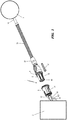
- Fig. 1
- in schematischer Darstellung eine Steckverbindung für eine Anschlussleitung zwischen einem Arbeitsgerät und einem Akkupack,
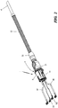
- Fig. 2
- eine Darstellung der Anschlussleitung nach
Fig. 1 mit in eine Steckbuchse der Steckverbindung eingestecktem Stecker, - Fig. 3
- einen Schnitt durch die Steckverbindung nach
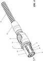
Fig. 2 , - Fig. 4
- in perspektivischer Darstellung einen Stecker der erfindungsgemäßen Steckverbindung,
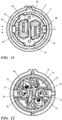
- Fig. 5
- eine Stirnansicht auf den Stecker gemäß Pfeil V in
Fig. 4 , - Fig. 6
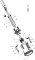
- eine Explosionsdarstellung des Steckers in seinen Einzelteilen,
- Fig. 7
- eine perspektivische Darstellung eines Steckergehäuses,
- Fig. 8
- einen Schnitt durch das Steckergehäuse nach
Fig. 7 , - Fig. 9
- einen Schnitt durch einen an einer Anschlussleitung montierten Stecker,
- Fig. 10
- eine schematische Darstellung der Anbindung eines metallischen Schutzschlauches an das Steckergehäuse,
- Fig. 11
- eine Stirnansicht auf eine Steckbuchse der Steckverbindung,
- Fig. 12
- eine Ansicht auf die Anschlussseite der Steckbuchse nach
Fig. 11 , - Fig. 13
- eine Explosionsdarstellung einer Steckbuchse der erfindungsgemäßen Steckverbindung,
- Fig. 14
- eine Seitenansicht eines am Steckkörper der Steckverbindung vorgesehenen Außenkontaktes,
- Fig. 15
- eine perspektivische Ansicht des Außenkontaktes nach
Fig. 14 , - Fig. 16
- eine Seitenansicht eines an einer Steckbuchse der Steckverbindung angeordneten Gegenkontaktes,
- Fig. 17
- eine perspektivische Darstellung des Gegenkontaktes nach
Fig. 16 , - Fig. 18
- in vergrößerter Darstellung ein Detail der Rastverbindung zwischen Stecker und Steckbuchse der Steckverbindung,
- Fig. 19
- in vergrößerter Darstellung die Rastverbindung zwischen Steckkörper und Steckbuchse der Steckverbindung,
- Fig. 20
- eine schematische Kurve des Kraftverlaufs beim Einstecken der Steckverbindung,
- Fig. 21
- eine schematische Darstellung des Kraftverlaufs beim Lösen der Steckverbindung,
- Fig. 22
- eine perspektivische Darstellung des Gegenkontaktes entsprechend
Fig. 17 mit einer im Kontaktbereich ausgebildeten Öffnung, - Fig. 23
- in vergrößerter Darstellung die Rastverbindung zwischen Steckkörper und Steckbuchse der Steckverbindung mit einem Gegenkontakt gem.
Fig. 22 , - Fig. 24
- eine schematische Darstellung der Kontaktierung zwischen einem Außenkontakt und einem Gegenkontakt der Steckverbindung.
- In den
Figuren 1 bis 3 ist eine erfindungsgemäße Steckverbindung 1 dargestellt, die im Ausführungsbeispiel zur lösbaren elektrischen Verbindung einer Anschlussleitung 16 mit einer Stromquelle, z. B. einem Akkupack 2 vorgesehen ist. Die Anschlussleitung 16 verbindet den Akkupack 2 mit einem elektrischen Arbeitsgerät 3, wobei zwischen der Anschlussleitung 16 und dem Arbeitsgerät 3 eine gleiche Steckverbindung wie zwischen Anschlussleitung 16 und Akkupack 2 vorgesehen sein kann. Die erfindungsgemäße Steckverbindung 1 ist unabhängig von der beispielhaft angegebenen Anwendung zwischen einem Akkupack 2 und einem Arbeitsgerät 3 und kann auch zur lösbaren Verbindung anderer elektrischer Anschlüsse vorgesehen sein. So ist allgemein mit der erfindungsgemäßen Steckverbindung eine beliebige Verbindung zwischen einer Stromquelle und einem Verbraucher herstellbar. Auch kann die Steckverbindung zum Anschluss einer Verlängerungsleitung an eine bestehende Anschlussleitung 16 verwendet werden. - Am Beispiel der Steckverbindung 1 zwischen der Anschlussleitung 16 und dem Akkupack 2 ist die Erfindung nachstehend erläutert.
- Die Steckverbindung 1 besteht aus einem Stecker 4 und einer Steckbuchse 8. Der Stecker 4 weist einen Steckkörper 5 und zumindest einen Steckkontakt 6, 7 auf. Im gezeigten Ausführungsbeispiel nach
Fig. 3 sind zwei Steckkontakte 6 und 7 vorgesehen. - Dem Stecker 4 ist die Steckbuchse 8 zugeordnet, in der zumindest eine Kontaktbuchse 9, 10 für den Steckkontakt 6, 7 des Steckkörpers 5 vorgesehen ist. Im gezeigten Ausführungsbeispiel nach
Fig. 3 sind zwei Kontaktbuchsen 9 und 10 vorgesehen. - Der Steckkörper 5 weist ferner im Bereich seiner Außenkontur zumindest einen Außenkontakt 11, 12 auf. Im Ausführungsbeispiel nach
Fig. 3 sind zwei Außenkontakte 11, 12 vorgesehen, die - bezogen auf eine Längsmittelachse 68 des Steckers 4 - einander insbesondere diametral gegenüber liegend angeordnet sind. Die relative Lage der Außenkontakte 11, 12 zueinander ist beispielhaft genannt; andere Lagen können zweckmäßig sein. Auch die Anzahl der Außenkontakte kann frei gewählt werden, so können z. B. auch drei oder mehr Außenkontakte vorgesehen sein. Einem Außenkontakt 11 bzw. 12 ist in der Steckbuchse 8 jeweils ein Gegenkontakt 13, 14 zugeordnet. Dabei bilden ein Außenkontakt 11, 12 mit dem zugeordneten Gegenkontakt 13, 14 vorzugsweise eine Rastverbindung 15, die in denFiguren 18 und 19 vergrößert dargestellt ist. - Die Anschlussleitung 16 ist vorzugsweise eine flexible Leitung, insbesondere eine kunststoffummantelte oder gummiummantelte Leitung. Die Anschlussleitung 16 weist im gezeigten Ausführungsbeispiel erste elektrische Leitungen 17, 18 zur Übertragung einer elektrischen Leistung auf. Ferner sind zweite elektrische Leitungen 19, 20 vorgesehen, die zur Übertragung von Signalen genutzt werden. Die ersten elektrischen Leitungen 17, 18 werden über die Steckverbindung 1 mit ersten Anschlussleitungen 97, 98 der Steckbuchse 8 zur Übertragung der elektrischen Leistung verbunden, während die zweiten elektrischen Leitungen 19, 20 über die Steckverbindung 1 zur Übertragung von Signalen mit zweiten Anschlussleitungen 99, 100 der Steckbuchse 8 verbunden werden. Die ersten Anschlussleitungen 97, 98 und die zweiten Anschlussleitungen 99, 100 sind an der Steckbuchse 8 kontaktiert.
- Die Ausbildung des Steckers 4 ist in den
Figuren 4 bis 10 wiedergegeben. Er besteht im Wesentlichen aus dem Steckkörper 5, einem mit dem Steckkörper 5 verbundenen Steckergehäuse 21 sowie einer Endhülse 22. - Das Steckergehäuse 21 liegt - wie
Fig. 6 zeigt - zwischen der Endhülse 22 und dem Steckkörper 5. Die elektrische Anschlussleitung 16 weist zwei erste Leitungen 17, 18 zur Leistungsübertragung und zwei zweite Leitungen 19, 20 für Signalübertragungen auf. Die zweiten Leitungen 19, 20 für die Signalübertragungen sind an den Außenkontakten 11, 12 angeschlossen; die ersten Leitungen 17, 18 sind mit den Steckkontakten 6, 7 verbunden. - Das Steckergehäuse 21 hat eine dem Steckkörper zugewandte Stirnseite 23, die eine Trennebene 24 (
Fig. 8 ) zwischen dem Steckkörper 5 und dem Steckergehäuse 21 definiert. Die Trennebene 24 ist zwischen einem Anschlussende 25 des Steckkörpers 5 und der Stirnseite 23 des Steckergehäuses 21 ausgebildet. Wie insbesondere dieFiguren 7 und 8 zeigen, weist das Steckergehäuse 21 Kupplungsfinger 26, 27, 28 auf, die die Trennebene 24 durchragen. Die Kupplungsfinger 26, 27, 28 stehen um eine Teillänge e über die Trennebene 24 vor. Es kann zweckmäßig sein, dass das Anschlussende 25 des Steckkörpers 5 alternativ oder ergänzend Kupplungsfinger trägt, die die Trennebene 24 durchragen. In der montierten Stellung gemäßFig. 9 ragen die Kupplungsfinger 26 in den Steckkörper 5 ein. Der Hohlraum 29 im Steckkörper 5 und der Hohlraum 30 im Steckergehäuse 21 werden bevorzugt nach Montage des Steckkörpers 5 an dem Steckergehäuse 21 mit einer Spritzgussmasse 31 verfüllt, insbesondere mit einer klebenden Spritzgussmasse 31 verfüllt. Hierzu kann eine Anspritzöffnung 90 (Fig. 8 ) im Steckergehäuse 21 vorgesehen sein. Der Steckkörper 5 ist mit seinem Anschlussende 25 fest mit dem Steckergehäuse 21 verbunden. Durch die Spritzgussmasse 31 ist auch das einragende Ende der Anschlussleitung 16 zugfest mit dem Stecker 4 verbunden. - Das Steckergehäuse 21 hat ein Einführende 32 für die Anschlussleitung 16. Zur Ausbildung eines Knickschutzes ist die Anschlussleitung 16 mit einem Schutzschlauch 33 versehen. Die Anschlussleitung 16 verläuft durch den Schutzschlauch 33, der im gezeigten Ausführungsbeispiel insbesondere als Metallgliederschlauch vorgesehen ist. Das dem Steckergehäuse 21 zugewandte Ende 34 des Schutzschlauches 33 kann vor der Montage aufgeweitet und in seinem Außendurchmesser A erweitert werden. Das Ende 34 erhält so einen Außendurchmesser A, der größer ist als ein Innendurchmesser I einer Endhülse 22. Mittels der Endhülse 22, die auf dem Einführende 32 fixiert wird, wird der Schutzschlauch 33 axial formschlüssig an dem Steckergehäuse 21 gehalten.
- Eine Aufweitung des Endes 34 des Schutzschlauches 33 kann auch in anderer Weise ausgeführt werden. So kann ein - vorzugsweis in der Endhülse 22 vorgesehener- Stopfen in das Ende 34 des Schutzschlauches 33 eingedrückt werden, um - vorteilhaft bei der Montage der Endhülse 22 - das Ende 34 in seinem Außendurchmesser A aufzuweiten und dadurch in der Endhülse 22 axial formschlüssig zu fixieren.
- Die Endhülse 22 wird axial über das Einführende 32 aufgeschoben, wobei zwischen dem Einführende 32 des Steckergehäuses 21 und dem Aufnahmeabschnitt 36 ein Rastring 35 wirkt, der als Federring ausgebildet ist und die Endhülse 22 formschlüssig auf dem Einführende 32 des Steckergehäuses 21 verrastet. Hierzu ist im Außenumfang des Einführendes 32 eine Außennut 37 und in der Endhülse 22 eine Innennut 38 vorgesehen.
- Wie die Stirnansicht auf das Steckende 39 des Steckkörpers 5 zeigt, liegt jeder Steckkontakt 6, 7 in einem zugeordneten Kontaktraum 46, 47. Die Kontakträume 46, 47 sind durch eine durchgehende Trennwand 40 voneinander getrennt. Die vorzugsweise als Flachkontakte ausgebildeten Steckkontakte 6, 7 liegen im gezeigten Ausführungsbeispiel in zueinander parallelen Ebenen; die Steckkontakte 6, 7 sind jedoch um einen Versatz v relativ zueinander verschoben, wie
Fig. 5 zeigt. Werden mehr als zwei Steckkontakte vorgesehen, können andere Relativlagen der Steckkontakte zueinander zweckmäßig sein. Sind beispielsweise drei Steckkontakte vorgesehen, können diese in Ebenen liegen, die in miteinander jeweils einen Winkel von insbesondere 120° einschließen. - Der Aufbau der Steckbuchse 8 ist in den
Figuren 11 bis 13 wiedergegeben. - Die Steckbuchse 8 weist einen Aufnahmeraum 42 auf, in dem der Steckkörper 5 aufgenommen ist. Die Steckkontakte 6, 7 greifen in Kontaktbuchsen 9, 10, die als Kontaktklemmen 43 zur Aufnahme der als Kontaktzungen 41 ausgebildeten Steckkontakte 6, 7 ausgebildet sind.
- Über den Umfang der Steckbuchse 8 versetzt liegen zwei Aufnahmenuten 44, 45 für am Steckkörper vorgesehene Positionsrippen 48, 49 (
Figuren 4 ,6 ). Im Ausführungsbeispiel haben die Positionsrippen 48, 49 in Umfangsrichtung eine unterschiedliche Breite entsprechend den vorgesehenen Aufnahmenuten 44 und 45. Die Aufnahmenuten 44, 45 und die Positionsrippen 48, 49 gewährleisten ein lagerichtiges Einstecken des Steckers 4 in Einschubrichtung 50 in die Steckbuchse 8. - Durch den Versatz v der Kontaktbuchsen 9, 10 bzw. der Steckkontakte 6, 7 wird auf der Anschlussseite 51 z. B. der Steckbuchse 8 ausreichend Raum geschaffen, um verschiedene Verbindungstechniken zum Anschluss der elektrischen Leitungen 17, 18, 19, 20 nutzen zu können. So ist in
Fig. 13 dargestellt, dass die Anschlussleitungen über Schraubkontakte, Lötkontakte, Crimpkontakte, Steckkontakte oder dgl. auf der Anschlussseite 51 (Fig. 12 ,13 ) der Kontaktbuchse 9 elektrisch angeschlossen werden können. - Die Kontaktbuchsen 9, 10 liegen im Boden der Steckbuchse 8. Die elektrischen Leitungen 17, 18 sind mit den Kontaktbuchsen 9, 10 verbunden und übertragen die zum Betrieb des Arbeitsgerätes 3 notwendige elektrische Leistung.
- Die Signalübertragung zwischen dem Arbeitsgerät 3 und dem Akkupack 2 erfolgt über die zweiten Leitungen 19, 20, die als Signalleitungen ausgebildet sind. Die Signalleitungen sind an Gegenkontakten 13, 14 angeschlossen. Ein derartiger Gegenkontakt 13, 14 ist als Federzunge 52 ausgebildet und an einem Ende 73 auf der Anschlussseite 51 der Steckbuchse 8 an deren Boden 54 festgelegt. Der blattfederartige Gegenkontakt 13, 14 liegt in einem Aufnahmeschlitz 55 der Steckbuchse 8, der in einer Umfangswand 56 der Steckbuchse 8 ausgebildet ist. Die Umfangswand 56 begrenzt einen Aufhahmeraum 42 für den Steckkörper 5. Der Gegenkontakt 13, 14 liegt radial außerhalb des Aufnahmeraums 42 und ragt mit einem freien Kontaktende 58 mit einem Überstand t durch den Aufnahmeschlitz 55 in der Umfangswand 56 in den Aufnahmeraum ein.
Fig. 11 zeigt die in den Aufnahmeraum 42 einragenden Kontaktenden 58 der Gegenkontakte 13, 14. - Mit den Gegenkontakten 13, 14 wirken die Außenkontakte 11, 12 (
Figuren 3 ,4 ) zusammen, wobei neben einer elektrischen Kontaktierung zwischen Außenkontakt und Gegenkontakt zugleich eine Rastverbindung 15 gebildet ist, wieFig. 3 zeigt. - Zur Bildung einer Rastverbindung 15 sind die Außenkontakte 11, 12 und die Gegenkontakte 13, 14 entsprechend den
Figuren 14 bis 17 ausgebildet. - Die
Figuren 14 und 15 zeigen einen Außenkontakt 11; der Außenkontakt 12 ist entsprechend ausgebildet. - Jeder Außenkontakt 11 hat ein Befestigungsende 60, mit dem der Außenkontakt im Material 57 des Steckkörpers 5 festgelegt ist. Bevorzugt weist das Befestigungsende 60 Rastzähne 61 auf, die vorteilhaft eine Verbindung des im Steckkörper 5 gehaltenen Außenkontakts 11 mit dem Steckergehäuse 21 herstellen. Das andere, freie Ende des Außenkontaktes 11 bildet eine Fixiernase 62, die in eine Öffnung 59 des Steckkörpers 5 eingreift, wie z. B.
Fig. 9 zeigt. Im Bereich der Fixiernase 62 weist der Außenkontakt 11 eine Rastvertiefung 63 auf. - In den
Figuren 16 und 17 ist am Beispiel des Gegenkontaktes 13 dessen Aufbau wiedergegeben. Der Gegenkontakt 14 entspricht dem Aufbau des Gegenkontaktes 13. - Der Gegenkontakt hat in Seitenansicht etwa die Form eines L mit abgewinkelten Schenkelenden. Der erste Schenkel 70 des Gegenkontakts 13 hat - wie
Fig. 17 zeigt - eine Befestigungsöffnung 71 zum Eingriff einer Befestigungsschraube 72, wieFig. 12 zeigt. Mittels des Schenkels 70 wird der Gegenkontakt am Boden 54 der Steckbuchse 8 mechanisch festgelegt. - Das abgewinkelte Ende 73 des Schenkels 70 steht zum Aufstecken eines Kabelschuhs aufrecht. Ferner ist im Schenkel 70 eine weitere Durchgangsbohrung 74 vorgesehen, in welche ein Zentrierdorn 75 des Bodens 54 der Steckbuchse 8 eingreift.
- Am freien Ende des Gegenkontaktes 13 ist das Kontaktende 58 ausgebildet. Das Kontaktende 58 hat in Seitenansicht etwa V-Form, wie
Fig. 16 zeigt. Das Kontaktende 58 hat einen gerundeten Kontaktbereich 76, wobei das Kontaktende 58 in einer Anschlagzunge 77 endet. Der Anschlagzunge 77 ist ein Gehäuseanschlag 78 an der Umfangswand 56 der Kontaktbuchse 8 zugeordnet, wie insbesondere die vergrößerten Darstellungen derFiguren 18 und 19 zeigen. - Die Anschlagzunge 77 begrenzt zusammen mit dem Gehäuseanschlag 78 den im Ruhezustand möglichen Überstand t (
Fig. 11 ) des Kontaktendes 58 in den Aufnahmeraum 42 der Steckbuchse 8. - Wie die
Figuren 18 und 19 zeigen, liegt in Einschubrichtung 50 des Steckkörpers 5 in die Aufnahmebuchse 8 vor der Rastvertiefung 63 im Außenkontakt 11 bzw. 12 eine Rampe 80. Die Rampe 80 beginnt auf einer Höhe, die etwa dem Überstand t des Kontaktendes 58 in den Aufnahmeraum 42 entspricht, wenn der Stecker 4 ausgezogen ist. Die Rampe 80 erhebt sich bis auf eine Höhe 81, die etwa dem Außenumfang U des Steckkörpers 5 entspricht. Die Höhe 81 liegt auf einer Höhe mit einem oberen Rand 65 der Rastvertiefung 63 (Fig. 14, 15 ). - Beim Einschieben des Steckers 4 in Einschubrichtung 50 wird - eine drehlagenrichtige Zuordnung des Steckkörpers 5 zur Steckbuchse 8 vorausgesetzt - das Steckende 39 axial in den Aufnahmeraum 42 der Steckbuchse 8 eintreten. Das Steckende 39 untergreift das Kontaktende 58, so dass dieses auf die Rampe 80 aufgleiten kann und gegen eine Federkraft in Pfeilrichtung 64 radial nach außen verdrängt wird. Ist mit der Höhe 81 die höchste Erhebung der Rampe 80 erreicht, gleitet der gerundete Kontaktbereich 76 des Kontaktendes 58 auf dem Außenumfang U des Steckkörpers 5, bis das Kontaktende 58 in die Rastvertiefung 63 eingreift. Das in der Rastvertiefung 63 liegende Kontaktende 58 stellt über den Kontaktbereich 76 eine elektrische Verbindung zwischen dem Außenkontakt 11 und dem Gegenkontakt 13 her. Zugleich ist eine mechanische Verriegelung des Steckers in der Steckbuchse 8 gegeben. Das Kontaktende 58 bildet somit zugleich eine Rastnase 66, die in die Rastvertiefung 63 eingreift.
- Die erfindungsgemäße Steckverbindung stellt nicht nur zuverlässig eine Verbindung zwischen leistungsübertragenden ersten Leitungen 17, 18 her, sondern zugleich eine Signalverbindung über zweite elektrische Leitungen 19, 20. Dabei kann aufgrund der Anordnung der Kontakte der Außendurchmesser der Steckverbindung klein gehalten werden.
- Darüber hinaus ist erfindungsgemäß gewährleistet, dass der Stecker mechanisch fixiert in der Steckbuchse 8 gesichert ist. Sowohl beim Einstecken des Steckers 4 in die Steckbuchse 8 als auch beim Herausziehen des Steckers 4 aus der Steckbuchse 8 muss der Benutzer eine Rastkraft überwinden. So zeigt
Fig. 20 den vom Benutzer auszuübenden Kraftverlauf gemäß der Kurve 85. Beim Einstecken des Steckers 4 in die Steckbuchse 8 steigt die vom Benutzer aufzubringende Steckkraft gemäß der Kurve 85 leicht an, bis die Rastnase 66 auf die Rampe 80 trifft. Die Einsteckkraft erhöht sich bis auf ein Maximum 86, bei dem die Rastnase 66 auf der maximalen Höhe 81 der Rampe 80 aufgeglitten ist. Nunmehr greift die Rastnase 66 in die Rastvertiefung 63 ein, wobei die vom Benutzer aufzubringende Kraft steil bis auf Null abfällt. Die Überwindung des Maximums 86 des Kraftverlaufs nach Kurve 85 gibt dem Benutzer eine haptische Rückmeldung, dass der Stecker 4 ordnungsgemäß in die Steckbuchse 8 eingesteckt ist. - Auch beim Ausstecken des Steckers 4 ergibt sich ein signifikanter Kraftverlauf gemäß Kurve 87 in
Fig. 21 . Zieht der Benutzer an dem Stecker 4, so muss er bereits nach kurzem Weg ein Maximum 88 an Kraft aufbringen, bevor sich der Stecker 4 aus der Steckbuchse 8 löst. Nach Überwindung des Maximums 88 sinkt die Kraft signifikant, so dass der Benutzer eine haptische Rückmeldung über das Lösen der Steckverbindung 1 erhält. - Die in den
Figuren 20 und 21 gezeigten Schwankungen im Kraftverlauf der Kurven 85, 87 sind durch Überlagerung der auftretenden Kräfte beim Stecken bzw. Lösen der Steckverbindung 1 durch die Steckkontakte 6, 7 und Kontaktbuchsen 9, 10 zur Übertragung der elektrischen Leistung und die unterschiedlich dazu ausgebildeten Außenkontakte 11, 12 und Gegenkontakte 13, 14 zur Signalübertragung bedingt. - Der in
Fig. 20 gezeigte signifikante Kraftabfall der Kurve 85 nach dem Maximum 86, insbesondere auf eine negative Kraft im Skalenbereich der X-Achse zwischen 9 und 10, ist durch das Einziehen der Rastnase 66 in die Rastvertiefung 63 begründet. Durch diese konstruktive Ausbildung und den sich daraus ergebenden Kraftverlauf ist gewährleistet, dass der Stecker 4 zwangsweise immer in eine Endposition gelangt; stabile Zwischenpositionen sind nicht möglich. Der beim Trennen der Steckverbindung 1 sich ergebende negative Kraftverlauf der Kurve 87 nach dem Maximum 88 ergibt sich durch die Rampe 80 am Steckkörper 5. Das Maximum 88 ist bestimmt durch das Ausheben der Rastnase 66 aus der Rastvertiefung 63. - In
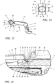
Fig. 22 ist perspektivisch die Darstellung eines Gegenkontaktes 13' gezeigt, wie er auch inFig. 17 dargestellt ist. Gleiche Teile tragen gleiche Bezugszeichen. - Im Unterschied zur Ausbildung des Gegenkontaktes 13 entsprechend
Fig. 17 weist der Gegenkontakt 13' inFig. 22 im Kontaktbereich 76 eine Öffnung 53 auf. Die Öffnung 53 hat eine sich in Breitenrichtung K des Kontaktbereichs 76 erstreckende Öffnungsweite W, die zweckmäßig gleich oder vorteilhaft größer als die Breite B (Fig. 15 ,24 ) des Außenkontaktes 11 ist. Die Öffnungsweite W der Öffnung 53 ist kleiner als die maximale Breite M (Fig. 24 ) des Kontaktbereichs 76. Die maximale Breite M des Kontaktbereichs 76 wird in Breitenrichtung K gemessen. - Die Öffnung 53 kann eine kreisrunde Form haben. Vorteilhaft können auch von der Kreisform abweichende Geometrien vorgesehen sein. Bevorzugt sind eine Kreisform, eine Ellipsenform, eine Quadratform oder eine Rechteckform. Bei einer Ellipse oder einem Rechteck erstreckt sich die größere Geometrieachse in Breitenrichtung K des Kontaktbereichs 76.
- In der vergrößerten Darstellung der Rastverbindung 15 zwischen dem Steckkörper 5 und der Steckbuchse der Steckverbindung 1 nach
Fig. 23 ist die Funktion der Öffnung 53 erkennbar. Die Darstellung inFig. 23 entspricht der inFig. 19 ; für gleiche Teile sind gleiche Bezugszeichen verwendet. - Durch die Öffnung 53 im Kontaktbereich 76 liegt der insbesondere als Steckzunge ausgebildete Außenkontakt 11 des Steckkörpers 5 in der Öffnungsfläche 79 der Öffnung 53. Die höchste Erhebung 67 des Kontaktbereiches 76 liegt höher als die Öffnungsfläche 79 der Öffnung 53. Die außerhalb der Öffnung 53 liegende höchste Erhebung 67 des Kontaktbereichs 76 liegt in der kontaktierten Stellung nach
Fig. 23 unterhalb des Bodens 69 der Rastvertiefung 63, wieFig. 23 zeigt. Die Öffnungsfläche 79 der Öffnung 53 liegt mit einem Höhenabstand a niedriger als die höchste Erhebung 67. - Die Öffnung 53 im Kontaktbereich 76 des insbesondere als Kontaktfeder ausgebildeten Gegenkontaktes 13 kann zumindest mit einem Teilbereich seines Öffnungsrandes 92 auf dem Boden 69 der Rastvertiefung 63 kontaktierend zur Anlage kommen. Dies ist schematisch in
Fig. 24 dargestellt. - In einer einfachen Ausführungsform kommen zumindest die Längskanten 82 und 83 (
Fig. 15 ,24 ) des Außenkontaktes 11 kontaktierend an dem Öffnungsrand 92 zur Anlage. InFig. 24 sind die sich aus der Anlage der Längskanten 82 und 83 am Öffnungsrand 92 ergebenden kontaktierenden Anlagepunkte 94 und 95 dargestellt. Aufgrund der Öffnung 53 ergibt sich an zumindest einer Längskante 82 oder 83 zumindest ein Anlagepunkt 94 oder 95. Insbesondere kann sich an der einen und der anderen Längskante 82 und 83 zumindest ein Anlagepunkt 94 oder 95 ergeben. In besonderer Ausgestaltung der Erfindung ergeben sich an jeder Längskante 82 und 83 jeweils zwei Anlagepunkte 94 und 95, wodurch die elektrische Kontaktierung zwischen dem Außenkontakt 11 und dem Gegenkontakt 13 durch insgesamt vier kontaktierende Anlagepunkte gegeben sind, die eine sichere Signalübertragung gewährleisten. - Es kann vorteilhaft sein, die Öffnung 53 derart auszubilden, dass der Öffnungsrand 92 mit zwei Randabschnitten 91 und 93 auf dem Boden 69 der Rastvertiefung 63 des Außenkontaktes 11 elektrisch kontaktierend aufliegt. Dies ist in
Fig. 24 strichliert dargestellt. Ein erster, vorderer Randabschnitt 91 erstreckt sich zwischen den vorderen Anlagepunkten 94 der Längskanten 82, 83. Ein zweiter, hinterer Randabschnitt 93 erstreckt sich zwischen den hinteren Anlagepunkten 95 der Längskanten 82, 83. Die kontaktierenden Randabschnitte 91 und 93 können auch nur teilweise kontaktierend auf dem Boden 69 der Rastvertiefung 63 aufliegen. Vorteilhaft liegen die Randabschnitte 91 und 93 über den gesamten Teilabschnitt des Öffnungsrandes 92 elektrisch kontaktierend auf dem Boden 69 der Rastvertiefung 63 auf. - Bevorzugt liegt die Öffnung 53 zentral im Kontaktbereich 76 des Gegenkontaktes 13. Wie die schematische Draufsicht nach
Fig. 24 zeigt, liegt die Öffnung 53 zweckmäßig symmetrisch zur höchsten Erhebung 67, insbesondere symmetrisch zur Höhenlinie 89 der höchsten Erhebung 67. - Weitere vorteilhafte Ausführungsbeispiele ergeben sich durch beliebige Kombination der Merkmale der vorstehend beschriebenen Ausführungsbeispiele.
Claims (18)
- Elektrische Steckverbindung zur lösbaren elektrischen Verbindung einer Stromquelle mit einem elektrischen Arbeitsgerät (3), wobei die Steckverbindung (1) zumindest eine erste elektrische Leitung (17, 18) zur Übertragung einer elektrischen Leistung und zumindest eine zweite elektrische Leitung (19, 20) zur Übertragung von Signalen umfasst, und die Steckverbindung (1) aus einem Stecker (4) mit einem Steckkörper (5) und einem oder mehreren ersten Steckkontakten (6, 7) und einer Steckbuchse (8) mit ersten Kontaktbuchsen (9, 10) besteht, und die Steckkontakte (6, 7) der ersten elektrischen Leitung (17, 18) innerhalb des Steckkörpers (5) angeordnet sind,
dadurch gekennzeichnet, dass der Steckkontakt der zweiten elektrischen Leitung (19, 20) als Außenkontakt (11, 12) im Bereich einer Außenkontur des Steckkörpers (5) ausgebildet ist, dass dem Außenkontakt (11, 12) des Steckkörpers (5) ein Gegenkontakt (13, 14) der Steckbuchse (8) zugeordnet ist, und dass der Außenkontakt (11, 12) und der Gegenkontakt (13, 14) eine Rastverbindung (15) bilden. - Steckverbindung nach Anspruch 1,
dadurch gekennzeichnet, dass der Außenkontakt (11, 12) am Außenumfang des Steckkörpers (5) angeordnet ist - Steckverbindung nach Anspruch 1 oder 2,
dadurch gekennzeichnet, dass der Gegenkontakt (13, 14) als Federzunge (52) ausgebildet ist. - Steckverbindung nach einem der Ansprüche 1 bis 3,
dadurch gekennzeichnet, dass der Außenkontakt (11, 12) eine Rastvertiefung (63) aufweist, der eine Rastnase (66) am Gegenkontakt (13, 14) zugeordnet ist. - Steckverbindung nach Anspruch 4,
dadurch gekennzeichnet, dass die Rastnase (66) durch das Kontaktende (58) des Gegenkontaktes (13, 14) gebildet ist. - Steckverbindung nach Anspruch 4,
dadurch gekennzeichnet, dass in Einschubrichtung (50) des Steckkörpers (5) vor dem Außenkontakt (11, 12) eine Rampe (80) ausgebildet ist. - Steckverbindung nach Anspruch 1,
dadurch gekennzeichnet, dass der Steckkörper (5) ein der Steckbuchse (8) zugewandtes Steckende (39) und ein an einem Steckergehäuse (21) gehaltenes Anschlussende (25) aufweist. - Steckverbindung nach Anspruch 7,
dadurch gekennzeichnet, dass zwischen dem Anschlussende (25) und dem Steckergehäuse (21) eine Trennebene (24) ausgebildet ist, und das Anschlussende (25) und/oder das Steckergehäuse (21) Kupplungsfinger (26, 27, 28) aufweist, die die Trennebene (24) durchragen. - Steckverbindung nach Anspruch 7 oder 8,
dadurch gekennzeichnet, dass der Steckkörper (5) und das Steckergehäuse (21) durch eine Spritzgussmasse (31) miteinander verbunden sind. - Steckverbindung nach Anspruch 1,
dadurch gekennzeichnet, dass die Steckbuchse (8) eine Umfangswand (56) aufweist, die einen Aufnahmeraum (42) begrenzt, dass der Gegenkontakt (13, 14) radial außerhalb der Umfangswand (56) liegt und mit einem freien Kontaktende (58) durch einen Aufnahmeschlitz (55) in der Umfangswand (56) in den Aufnahmeraum (43) einragt. - Steckverbindung nach Anspruch 10,
dadurch gekennzeichnet, dass das Kontaktende (58) eine Anschlagzunge (77) aufweist, die einen in den Aufnahmeraum (42) einragenden Überstand (t) des Kontaktendes (58) begrenzt. - Steckverbindung nach Anspruch 1,
dadurch gekennzeichnet, dass in Stirnansicht auf den Steckkörper (5) die Steckkontakte (6, 7) der ersten elektrischen Leitungen (17, 18) mit einem Abstand (v) zueinander versetzt liegen. - Steckverbindung nach Anspruch 1,
dadurch gekennzeichnet, dass die Steckkontakte (6, 7) als Kontaktzungen (41) ausgebildet sind, die mit als Kontaktklemmen (43) ausgebildeten Kontaktbuchsen (9, 10) zusammenwirken. - Steckverbindung nach Anspruch 1,
dadurch gekennzeichnet, dass der Gegenkontakt (13, 14) der Steckbuchse (8) einen Kontaktbereich (76) zur elektrischen Kontaktierung des Außenkontaktes (11, 12) aufweist, und dass im Kontaktbereich (76) des Gegenkontaktes (13, 14) eine Öffnung (53) ausgebildet ist. - Steckverbindung nach Anspruch 14,
dadurch gekennzeichnet, dass der Kontaktbereich (76) eine höchste Erhebung (67) aufweist und die Öffnungsfläche (79) der Öffnung (53) mit einem Höhenabstand (a) unterhalb der höchsten Erhebung (67) liegt. - Steckverbindung nach Anspruch 14,
dadurch gekennzeichnet, dass die Öffnungsweite (W) der Öffnung (53) breiter ist als die Breite (B) des Außenkontaktes (11, 12). - Steckverbindung nach Anspruch 14,
dadurch gekennzeichnet, dass der Außenkontakt (11, 12) zwei Längskanten (82, 83) aufweist, und dass die Längskanten (82, 83) in zumindest einem Anlagepunkt (94, 95) an einem Öffnungsrand (92) der Öffnung (93) elektrisch kontaktierend anliegen. - Steckverbindung nach Anspruch 14,
dadurch gekennzeichnet, dass ein Öffnungsrand (92) der Öffnung (93) mit einem Randabschnitt (91, 93) an dem Außenkontakt (11, 12) elektrisch kontaktierend anliegt.
Applications Claiming Priority (1)
| Application Number | Priority Date | Filing Date | Title |
|---|---|---|---|
| DE102017000996.1A DE102017000996A1 (de) | 2017-01-30 | 2017-01-30 | Elektrische Steckverbindung zwischen einer Stromquelle und einem elektrischen Arbeitsgerät |
Publications (2)
| Publication Number | Publication Date |
|---|---|
| EP3355416A1 true EP3355416A1 (de) | 2018-08-01 |
| EP3355416B1 EP3355416B1 (de) | 2023-08-02 |
Family
ID=61027584
Family Applications (1)
| Application Number | Title | Priority Date | Filing Date |
|---|---|---|---|
| EP18153488.4A Active EP3355416B1 (de) | 2017-01-30 | 2018-01-25 | Elektrische steckverbindung zwischen einer stromquelle und einem elektrischen arbeitsgerät |
Country Status (4)
| Country | Link |
|---|---|
| US (1) | US10424883B2 (de) |
| EP (1) | EP3355416B1 (de) |
| CN (1) | CN108376853B (de) |
| DE (1) | DE102017000996A1 (de) |
Families Citing this family (2)
| Publication number | Priority date | Publication date | Assignee | Title |
|---|---|---|---|---|
| CN112467435B (zh) * | 2019-09-06 | 2024-08-16 | 泰科电子(上海)有限公司 | 连接器组合、插头以及插座 |
| DE102020000422A1 (de) | 2020-01-24 | 2021-07-29 | Drägerwerk AG & Co. KGaA | Elektrische Steckverbindung für eine Medizingeräteanordnung |
Citations (2)
| Publication number | Priority date | Publication date | Assignee | Title |
|---|---|---|---|---|
| US20070032102A1 (en) * | 2005-08-08 | 2007-02-08 | Hon Hai Precision Ind. Co., Ltd. | Land grid array connector contact |
| US20150072562A1 (en) * | 2013-07-19 | 2015-03-12 | Hon Hai Precision Industry Co., Ltd. | Flippable electrical connector |
Family Cites Families (13)
| Publication number | Priority date | Publication date | Assignee | Title |
|---|---|---|---|---|
| US5941726A (en) * | 1996-11-27 | 1999-08-24 | The Whitaker Corporation | Interlocking release latching system for electrical connector |
| US6682356B2 (en) * | 2002-03-14 | 2004-01-27 | Wingcast, Llc | Peripheral device port for motor vehicles |
| US6855003B1 (en) * | 2003-10-14 | 2005-02-15 | Brunswick Corporation | Multiple use connector for a GPS system on a marine vessel |
| US7001201B1 (en) * | 2004-10-08 | 2006-02-21 | Action Electronics Co., Ltd. | Multi-function electrical connector |
| TWM288983U (en) * | 2005-08-08 | 2006-03-21 | Hon Hai Prec Ind Co Ltd | Electrical contact of connector |
| CN201576831U (zh) * | 2009-10-10 | 2010-09-08 | 富士康(昆山)电脑接插件有限公司 | 电连接器 |
| US8465300B2 (en) * | 2011-09-14 | 2013-06-18 | Primesource Telecom Inc. | Cable installation assembly |
| KR102011385B1 (ko) * | 2012-11-12 | 2019-08-16 | 앱티브 테크놀러지스 리미티드 | 자동 이차 로크를 갖는 커넥터 조립체 |
| EP2840664B1 (de) * | 2013-08-20 | 2016-06-08 | Delphi Technologies, Inc. | Verbinderanordnung mit federbetätigter Sekundärverriegelung |
| CN204179274U (zh) * | 2013-09-08 | 2015-02-25 | 富士康(昆山)电脑接插件有限公司 | 电连接器组合 |
| US9608349B2 (en) * | 2014-08-06 | 2017-03-28 | Ddk Ltd. | Contact having two contact portions with their central lines in one plane |
| CN105529554B (zh) * | 2015-06-03 | 2019-05-31 | 连展科技(深圳)有限公司 | 插头电连接器 |
| CN205029053U (zh) * | 2015-09-06 | 2016-02-10 | 番禺得意精密电子工业有限公司 | 电连接器 |
-
2017
- 2017-01-30 DE DE102017000996.1A patent/DE102017000996A1/de active Pending
-
2018
- 2018-01-25 EP EP18153488.4A patent/EP3355416B1/de active Active
- 2018-01-30 CN CN201810088827.0A patent/CN108376853B/zh active Active
- 2018-01-30 US US15/884,220 patent/US10424883B2/en active Active
Patent Citations (2)
| Publication number | Priority date | Publication date | Assignee | Title |
|---|---|---|---|---|
| US20070032102A1 (en) * | 2005-08-08 | 2007-02-08 | Hon Hai Precision Ind. Co., Ltd. | Land grid array connector contact |
| US20150072562A1 (en) * | 2013-07-19 | 2015-03-12 | Hon Hai Precision Industry Co., Ltd. | Flippable electrical connector |
Also Published As
| Publication number | Publication date |
|---|---|
| EP3355416B1 (de) | 2023-08-02 |
| CN108376853A (zh) | 2018-08-07 |
| DE102017000996A1 (de) | 2018-08-02 |
| CN108376853B (zh) | 2021-09-07 |
| US10424883B2 (en) | 2019-09-24 |
| US20180219337A1 (en) | 2018-08-02 |
Similar Documents
| Publication | Publication Date | Title |
|---|---|---|
| DE60001437T2 (de) | Elektrische Verbinderanordnung mit Abschirmung zur unmittelbaren Befestigung an Geräte | |
| DE2218631A1 (de) | Elektrische Anschlußbuchse | |
| EP0772261A2 (de) | Koaxial-Steckverbindung | |
| EP3719933A1 (de) | Steckverbindungsvorrichtung mit wenigstens einem steckverbinder | |
| EP1920504B1 (de) | Steckernetzgerät mit auswechselbarer netzsteckereinheit | |
| DE2549597A1 (de) | Kupplungsanordnung fuer verbindbare enden elektrischer leitungen | |
| DE102016006598A1 (de) | Steckverbinder | |
| WO2004097995A1 (de) | Elektrische steckkupplung | |
| DE3705739C2 (de) | Elektrische Verbinderanordnung | |
| WO2023174813A1 (de) | Geschirmter pushpull-stecker mit schirmfeder | |
| EP1306933B1 (de) | Führungssystem für Kontaktstecker | |
| DE10233251A1 (de) | Joch für eine elektromagnetische Kupplung | |
| DE102015114080A1 (de) | Elektrischer steckverbinder und damit ausgestattete elektrische steckverbindung | |
| DE102017222809A1 (de) | Elektrischer Steckverbinder und Steckverbindung | |
| DE7915035U1 (de) | Elektrische Anschlußvorrichtung | |
| DE102016102036A1 (de) | Elektrischer Steckkontakt | |
| EP3355416B1 (de) | Elektrische steckverbindung zwischen einer stromquelle und einem elektrischen arbeitsgerät | |
| DE4123011C2 (de) | Verbinder für Koaxialkabel | |
| DE10041430A1 (de) | Steckverbindung mit Verriegelungsmechanismus | |
| DE2413445C2 (de) | Elektrischer Zwittersteckverbinder | |
| DE19532623B4 (de) | Elektrischer Stecker mit einem Betätigungsschieber | |
| EP2026416B1 (de) | Kabelaufnahmevorrichtung und Kontaktsystem | |
| DE102004021343B4 (de) | Elektrische Steckverbindung mit einem elektrischen Buchsenteil | |
| DE102022134013A1 (de) | Steckverbinderteil mit entriegelbarem Steckelement | |
| DE202017107625U1 (de) | Elektrischer Steckverbinder |
Legal Events
| Date | Code | Title | Description |
|---|---|---|---|
| PUAI | Public reference made under article 153(3) epc to a published international application that has entered the european phase |
Free format text: ORIGINAL CODE: 0009012 |
|
| STAA | Information on the status of an ep patent application or granted ep patent |
Free format text: STATUS: THE APPLICATION HAS BEEN PUBLISHED |
|
| AK | Designated contracting states |
Kind code of ref document: A1 Designated state(s): AL AT BE BG CH CY CZ DE DK EE ES FI FR GB GR HR HU IE IS IT LI LT LU LV MC MK MT NL NO PL PT RO RS SE SI SK SM TR |
|
| AX | Request for extension of the european patent |
Extension state: BA ME |
|
| RIN1 | Information on inventor provided before grant (corrected) |
Inventor name: BAHNER, DANIEL Inventor name: LUZ, JOCHEN Inventor name: MAIER, MARKUS Inventor name: KOLB, JOACHIM Inventor name: NORDMANN, ALEXANDER |
|
| STAA | Information on the status of an ep patent application or granted ep patent |
Free format text: STATUS: REQUEST FOR EXAMINATION WAS MADE |
|
| 17P | Request for examination filed |
Effective date: 20190111 |
|
| RBV | Designated contracting states (corrected) |
Designated state(s): AL AT BE BG CH CY CZ DE DK EE ES FI FR GB GR HR HU IE IS IT LI LT LU LV MC MK MT NL NO PL PT RO RS SE SI SK SM TR |
|
| STAA | Information on the status of an ep patent application or granted ep patent |
Free format text: STATUS: EXAMINATION IS IN PROGRESS |
|
| 17Q | First examination report despatched |
Effective date: 20191118 |
|
| GRAP | Despatch of communication of intention to grant a patent |
Free format text: ORIGINAL CODE: EPIDOSNIGR1 |
|
| STAA | Information on the status of an ep patent application or granted ep patent |
Free format text: STATUS: GRANT OF PATENT IS INTENDED |
|
| INTG | Intention to grant announced |
Effective date: 20230227 |
|
| GRAS | Grant fee paid |
Free format text: ORIGINAL CODE: EPIDOSNIGR3 |
|
| GRAA | (expected) grant |
Free format text: ORIGINAL CODE: 0009210 |
|
| STAA | Information on the status of an ep patent application or granted ep patent |
Free format text: STATUS: THE PATENT HAS BEEN GRANTED |
|
| AK | Designated contracting states |
Kind code of ref document: B1 Designated state(s): AL AT BE BG CH CY CZ DE DK EE ES FI FR GB GR HR HU IE IS IT LI LT LU LV MC MK MT NL NO PL PT RO RS SE SI SK SM TR |
|
| REG | Reference to a national code |
Ref country code: GB Ref legal event code: FG4D Free format text: NOT ENGLISH |
|
| REG | Reference to a national code |
Ref country code: CH Ref legal event code: EP |
|
| REG | Reference to a national code |
Ref country code: DE Ref legal event code: R096 Ref document number: 502018012823 Country of ref document: DE |
|
| REG | Reference to a national code |
Ref country code: IE Ref legal event code: FG4D Free format text: LANGUAGE OF EP DOCUMENT: GERMAN |
|
| REG | Reference to a national code |
Ref country code: LT Ref legal event code: MG9D |
|
| REG | Reference to a national code |
Ref country code: NL Ref legal event code: MP Effective date: 20230802 |
|
| PG25 | Lapsed in a contracting state [announced via postgrant information from national office to epo] |
Ref country code: GR Free format text: LAPSE BECAUSE OF FAILURE TO SUBMIT A TRANSLATION OF THE DESCRIPTION OR TO PAY THE FEE WITHIN THE PRESCRIBED TIME-LIMIT Effective date: 20231103 |
|
| PG25 | Lapsed in a contracting state [announced via postgrant information from national office to epo] |
Ref country code: IS Free format text: LAPSE BECAUSE OF FAILURE TO SUBMIT A TRANSLATION OF THE DESCRIPTION OR TO PAY THE FEE WITHIN THE PRESCRIBED TIME-LIMIT Effective date: 20231202 |
|
| PG25 | Lapsed in a contracting state [announced via postgrant information from national office to epo] |
Ref country code: SE Free format text: LAPSE BECAUSE OF FAILURE TO SUBMIT A TRANSLATION OF THE DESCRIPTION OR TO PAY THE FEE WITHIN THE PRESCRIBED TIME-LIMIT Effective date: 20230802 Ref country code: RS Free format text: LAPSE BECAUSE OF FAILURE TO SUBMIT A TRANSLATION OF THE DESCRIPTION OR TO PAY THE FEE WITHIN THE PRESCRIBED TIME-LIMIT Effective date: 20230802 Ref country code: PT Free format text: LAPSE BECAUSE OF FAILURE TO SUBMIT A TRANSLATION OF THE DESCRIPTION OR TO PAY THE FEE WITHIN THE PRESCRIBED TIME-LIMIT Effective date: 20231204 Ref country code: NO Free format text: LAPSE BECAUSE OF FAILURE TO SUBMIT A TRANSLATION OF THE DESCRIPTION OR TO PAY THE FEE WITHIN THE PRESCRIBED TIME-LIMIT Effective date: 20231102 Ref country code: NL Free format text: LAPSE BECAUSE OF FAILURE TO SUBMIT A TRANSLATION OF THE DESCRIPTION OR TO PAY THE FEE WITHIN THE PRESCRIBED TIME-LIMIT Effective date: 20230802 Ref country code: LV Free format text: LAPSE BECAUSE OF FAILURE TO SUBMIT A TRANSLATION OF THE DESCRIPTION OR TO PAY THE FEE WITHIN THE PRESCRIBED TIME-LIMIT Effective date: 20230802 Ref country code: LT Free format text: LAPSE BECAUSE OF FAILURE TO SUBMIT A TRANSLATION OF THE DESCRIPTION OR TO PAY THE FEE WITHIN THE PRESCRIBED TIME-LIMIT Effective date: 20230802 Ref country code: IS Free format text: LAPSE BECAUSE OF FAILURE TO SUBMIT A TRANSLATION OF THE DESCRIPTION OR TO PAY THE FEE WITHIN THE PRESCRIBED TIME-LIMIT Effective date: 20231202 Ref country code: HR Free format text: LAPSE BECAUSE OF FAILURE TO SUBMIT A TRANSLATION OF THE DESCRIPTION OR TO PAY THE FEE WITHIN THE PRESCRIBED TIME-LIMIT Effective date: 20230802 Ref country code: GR Free format text: LAPSE BECAUSE OF FAILURE TO SUBMIT A TRANSLATION OF THE DESCRIPTION OR TO PAY THE FEE WITHIN THE PRESCRIBED TIME-LIMIT Effective date: 20231103 Ref country code: FI Free format text: LAPSE BECAUSE OF FAILURE TO SUBMIT A TRANSLATION OF THE DESCRIPTION OR TO PAY THE FEE WITHIN THE PRESCRIBED TIME-LIMIT Effective date: 20230802 |
|
| PG25 | Lapsed in a contracting state [announced via postgrant information from national office to epo] |
Ref country code: PL Free format text: LAPSE BECAUSE OF FAILURE TO SUBMIT A TRANSLATION OF THE DESCRIPTION OR TO PAY THE FEE WITHIN THE PRESCRIBED TIME-LIMIT Effective date: 20230802 |
|
| PG25 | Lapsed in a contracting state [announced via postgrant information from national office to epo] |
Ref country code: ES Free format text: LAPSE BECAUSE OF FAILURE TO SUBMIT A TRANSLATION OF THE DESCRIPTION OR TO PAY THE FEE WITHIN THE PRESCRIBED TIME-LIMIT Effective date: 20230802 |
|
| PG25 | Lapsed in a contracting state [announced via postgrant information from national office to epo] |
Ref country code: SM Free format text: LAPSE BECAUSE OF FAILURE TO SUBMIT A TRANSLATION OF THE DESCRIPTION OR TO PAY THE FEE WITHIN THE PRESCRIBED TIME-LIMIT Effective date: 20230802 Ref country code: RO Free format text: LAPSE BECAUSE OF FAILURE TO SUBMIT A TRANSLATION OF THE DESCRIPTION OR TO PAY THE FEE WITHIN THE PRESCRIBED TIME-LIMIT Effective date: 20230802 Ref country code: ES Free format text: LAPSE BECAUSE OF FAILURE TO SUBMIT A TRANSLATION OF THE DESCRIPTION OR TO PAY THE FEE WITHIN THE PRESCRIBED TIME-LIMIT Effective date: 20230802 Ref country code: EE Free format text: LAPSE BECAUSE OF FAILURE TO SUBMIT A TRANSLATION OF THE DESCRIPTION OR TO PAY THE FEE WITHIN THE PRESCRIBED TIME-LIMIT Effective date: 20230802 Ref country code: DK Free format text: LAPSE BECAUSE OF FAILURE TO SUBMIT A TRANSLATION OF THE DESCRIPTION OR TO PAY THE FEE WITHIN THE PRESCRIBED TIME-LIMIT Effective date: 20230802 Ref country code: CZ Free format text: LAPSE BECAUSE OF FAILURE TO SUBMIT A TRANSLATION OF THE DESCRIPTION OR TO PAY THE FEE WITHIN THE PRESCRIBED TIME-LIMIT Effective date: 20230802 Ref country code: SK Free format text: LAPSE BECAUSE OF FAILURE TO SUBMIT A TRANSLATION OF THE DESCRIPTION OR TO PAY THE FEE WITHIN THE PRESCRIBED TIME-LIMIT Effective date: 20230802 |
|
| REG | Reference to a national code |
Ref country code: DE Ref legal event code: R097 Ref document number: 502018012823 Country of ref document: DE |
|
| PG25 | Lapsed in a contracting state [announced via postgrant information from national office to epo] |
Ref country code: IT Free format text: LAPSE BECAUSE OF FAILURE TO SUBMIT A TRANSLATION OF THE DESCRIPTION OR TO PAY THE FEE WITHIN THE PRESCRIBED TIME-LIMIT Effective date: 20230802 |
|
| PGFP | Annual fee paid to national office [announced via postgrant information from national office to epo] |
Ref country code: FR Payment date: 20240125 Year of fee payment: 7 |
|
| PLBE | No opposition filed within time limit |
Free format text: ORIGINAL CODE: 0009261 |
|
| STAA | Information on the status of an ep patent application or granted ep patent |
Free format text: STATUS: NO OPPOSITION FILED WITHIN TIME LIMIT |
|
| 26N | No opposition filed |
Effective date: 20240503 |
|
| PG25 | Lapsed in a contracting state [announced via postgrant information from national office to epo] |
Ref country code: SI Free format text: LAPSE BECAUSE OF FAILURE TO SUBMIT A TRANSLATION OF THE DESCRIPTION OR TO PAY THE FEE WITHIN THE PRESCRIBED TIME-LIMIT Effective date: 20230802 |
|
| PG25 | Lapsed in a contracting state [announced via postgrant information from national office to epo] |
Ref country code: MC Free format text: LAPSE BECAUSE OF FAILURE TO SUBMIT A TRANSLATION OF THE DESCRIPTION OR TO PAY THE FEE WITHIN THE PRESCRIBED TIME-LIMIT Effective date: 20230802 |
|
| PG25 | Lapsed in a contracting state [announced via postgrant information from national office to epo] |
Ref country code: MC Free format text: LAPSE BECAUSE OF FAILURE TO SUBMIT A TRANSLATION OF THE DESCRIPTION OR TO PAY THE FEE WITHIN THE PRESCRIBED TIME-LIMIT Effective date: 20230802 |
|
| REG | Reference to a national code |
Ref country code: CH Ref legal event code: PL |
|
| PG25 | Lapsed in a contracting state [announced via postgrant information from national office to epo] |
Ref country code: LU Free format text: LAPSE BECAUSE OF NON-PAYMENT OF DUE FEES Effective date: 20240125 |
|
| GBPC | Gb: european patent ceased through non-payment of renewal fee |
Effective date: 20240125 |
|
| PG25 | Lapsed in a contracting state [announced via postgrant information from national office to epo] |
Ref country code: LU Free format text: LAPSE BECAUSE OF NON-PAYMENT OF DUE FEES Effective date: 20240125 |
|
| PG25 | Lapsed in a contracting state [announced via postgrant information from national office to epo] |
Ref country code: GB Free format text: LAPSE BECAUSE OF NON-PAYMENT OF DUE FEES Effective date: 20240125 |
|
| PG25 | Lapsed in a contracting state [announced via postgrant information from national office to epo] |
Ref country code: BE Free format text: LAPSE BECAUSE OF NON-PAYMENT OF DUE FEES Effective date: 20240131 |
|
| PG25 | Lapsed in a contracting state [announced via postgrant information from national office to epo] |
Ref country code: CH Free format text: LAPSE BECAUSE OF NON-PAYMENT OF DUE FEES Effective date: 20240131 |
|
| PG25 | Lapsed in a contracting state [announced via postgrant information from national office to epo] |
Ref country code: GB Free format text: LAPSE BECAUSE OF NON-PAYMENT OF DUE FEES Effective date: 20240125 Ref country code: CH Free format text: LAPSE BECAUSE OF NON-PAYMENT OF DUE FEES Effective date: 20240131 Ref country code: BE Free format text: LAPSE BECAUSE OF NON-PAYMENT OF DUE FEES Effective date: 20240131 |
|
| REG | Reference to a national code |
Ref country code: BE Ref legal event code: MM Effective date: 20240131 |
|
| PG25 | Lapsed in a contracting state [announced via postgrant information from national office to epo] |
Ref country code: BG Free format text: LAPSE BECAUSE OF FAILURE TO SUBMIT A TRANSLATION OF THE DESCRIPTION OR TO PAY THE FEE WITHIN THE PRESCRIBED TIME-LIMIT Effective date: 20230802 |
|
| PG25 | Lapsed in a contracting state [announced via postgrant information from national office to epo] |
Ref country code: BG Free format text: LAPSE BECAUSE OF FAILURE TO SUBMIT A TRANSLATION OF THE DESCRIPTION OR TO PAY THE FEE WITHIN THE PRESCRIBED TIME-LIMIT Effective date: 20230802 |
|
| PG25 | Lapsed in a contracting state [announced via postgrant information from national office to epo] |
Ref country code: IE Free format text: LAPSE BECAUSE OF NON-PAYMENT OF DUE FEES Effective date: 20240125 |
|
| PG25 | Lapsed in a contracting state [announced via postgrant information from national office to epo] |
Ref country code: IE Free format text: LAPSE BECAUSE OF NON-PAYMENT OF DUE FEES Effective date: 20240125 |
|
| REG | Reference to a national code |
Ref country code: AT Ref legal event code: MM01 Ref document number: 1595886 Country of ref document: AT Kind code of ref document: T Effective date: 20240125 |
|
| PG25 | Lapsed in a contracting state [announced via postgrant information from national office to epo] |
Ref country code: AT Free format text: LAPSE BECAUSE OF NON-PAYMENT OF DUE FEES Effective date: 20240125 |
|
| PG25 | Lapsed in a contracting state [announced via postgrant information from national office to epo] |
Ref country code: CY Free format text: LAPSE BECAUSE OF FAILURE TO SUBMIT A TRANSLATION OF THE DESCRIPTION OR TO PAY THE FEE WITHIN THE PRESCRIBED TIME-LIMIT; INVALID AB INITIO Effective date: 20180125 |
|
| PG25 | Lapsed in a contracting state [announced via postgrant information from national office to epo] |
Ref country code: HU Free format text: LAPSE BECAUSE OF FAILURE TO SUBMIT A TRANSLATION OF THE DESCRIPTION OR TO PAY THE FEE WITHIN THE PRESCRIBED TIME-LIMIT; INVALID AB INITIO Effective date: 20180125 |
|
| PG25 | Lapsed in a contracting state [announced via postgrant information from national office to epo] |
Ref country code: FR Free format text: LAPSE BECAUSE OF NON-PAYMENT OF DUE FEES Effective date: 20250131 |
|
| PG25 | Lapsed in a contracting state [announced via postgrant information from national office to epo] |
Ref country code: TR Free format text: LAPSE BECAUSE OF FAILURE TO SUBMIT A TRANSLATION OF THE DESCRIPTION OR TO PAY THE FEE WITHIN THE PRESCRIBED TIME-LIMIT Effective date: 20230802 |
|
| PGFP | Annual fee paid to national office [announced via postgrant information from national office to epo] |
Ref country code: DE Payment date: 20260127 Year of fee payment: 9 |