EP3355268A1 - Procédé, dispositif de calcul et système de mesure d'une radiographie d'une zone d'examen médicale - Google Patents
Procédé, dispositif de calcul et système de mesure d'une radiographie d'une zone d'examen médicale Download PDFInfo
- Publication number
- EP3355268A1 EP3355268A1 EP18153407.4A EP18153407A EP3355268A1 EP 3355268 A1 EP3355268 A1 EP 3355268A1 EP 18153407 A EP18153407 A EP 18153407A EP 3355268 A1 EP3355268 A1 EP 3355268A1
- Authority
- EP
- European Patent Office
- Prior art keywords
- virtual
- ray image
- projection direction
- model
- measuring
- Prior art date
- Legal status (The legal status is an assumption and is not a legal conclusion. Google has not performed a legal analysis and makes no representation as to the accuracy of the status listed.)
- Granted
Links
- 238000000034 method Methods 0.000 title claims abstract description 52
- 238000005259 measurement Methods 0.000 claims description 65
- 238000003384 imaging method Methods 0.000 claims description 8
- 238000005457 optimization Methods 0.000 claims description 8
- 238000004590 computer program Methods 0.000 claims description 7
- 238000012937 correction Methods 0.000 claims description 7
- 230000006870 function Effects 0.000 claims description 6
- 230000008859 change Effects 0.000 claims description 5
- 238000002591 computed tomography Methods 0.000 claims description 5
- 238000013528 artificial neural network Methods 0.000 claims description 4
- 230000005489 elastic deformation Effects 0.000 claims description 4
- 238000010801 machine learning Methods 0.000 claims description 3
- 238000003325 tomography Methods 0.000 claims description 3
- 238000004364 calculation method Methods 0.000 claims description 2
- 230000005855 radiation Effects 0.000 claims description 2
- 210000000988 bone and bone Anatomy 0.000 description 5
- 238000005520 cutting process Methods 0.000 description 5
- 206010028980 Neoplasm Diseases 0.000 description 4
- 238000003745 diagnosis Methods 0.000 description 3
- 239000007943 implant Substances 0.000 description 3
- 230000000877 morphologic effect Effects 0.000 description 3
- 210000000056 organ Anatomy 0.000 description 3
- 230000009466 transformation Effects 0.000 description 3
- 239000013598 vector Substances 0.000 description 3
- PXFBZOLANLWPMH-UHFFFAOYSA-N 16-Epiaffinine Natural products C1C(C2=CC=CC=C2N2)=C2C(=O)CC2C(=CC)CN(C)C1C2CO PXFBZOLANLWPMH-UHFFFAOYSA-N 0.000 description 2
- 230000006978 adaptation Effects 0.000 description 2
- 230000008901 benefit Effects 0.000 description 2
- 230000000052 comparative effect Effects 0.000 description 2
- 238000011156 evaluation Methods 0.000 description 2
- 238000002595 magnetic resonance imaging Methods 0.000 description 2
- 238000012986 modification Methods 0.000 description 2
- 230000004048 modification Effects 0.000 description 2
- 238000002360 preparation method Methods 0.000 description 2
- 230000008569 process Effects 0.000 description 2
- 206010039722 scoliosis Diseases 0.000 description 2
- 238000004088 simulation Methods 0.000 description 2
- 238000012935 Averaging Methods 0.000 description 1
- 241001077885 Gesta Species 0.000 description 1
- 241001465754 Metazoa Species 0.000 description 1
- 241000275031 Nica Species 0.000 description 1
- 238000004458 analytical method Methods 0.000 description 1
- 238000011511 automated evaluation Methods 0.000 description 1
- 238000004422 calculation algorithm Methods 0.000 description 1
- 201000010099 disease Diseases 0.000 description 1
- 208000037265 diseases, disorders, signs and symptoms Diseases 0.000 description 1
- 239000012530 fluid Substances 0.000 description 1
- 238000002594 fluoroscopy Methods 0.000 description 1
- 230000003993 interaction Effects 0.000 description 1
- 238000004519 manufacturing process Methods 0.000 description 1
- 238000013178 mathematical model Methods 0.000 description 1
- 230000001575 pathological effect Effects 0.000 description 1
- 230000000149 penetrating effect Effects 0.000 description 1
- 230000000704 physical effect Effects 0.000 description 1
- 230000036544 posture Effects 0.000 description 1
- 238000012545 processing Methods 0.000 description 1
- 238000012552 review Methods 0.000 description 1
- 238000004904 shortening Methods 0.000 description 1
- 230000003068 static effect Effects 0.000 description 1
- 238000003860 storage Methods 0.000 description 1
- 230000002123 temporal effect Effects 0.000 description 1
- 238000012546 transfer Methods 0.000 description 1
- 238000013519 translation Methods 0.000 description 1
- 210000001835 viscera Anatomy 0.000 description 1
Images


Classifications
-
- A—HUMAN NECESSITIES
- A61—MEDICAL OR VETERINARY SCIENCE; HYGIENE
- A61B—DIAGNOSIS; SURGERY; IDENTIFICATION
- A61B6/00—Apparatus or devices for radiation diagnosis; Apparatus or devices for radiation diagnosis combined with radiation therapy equipment
- A61B6/58—Testing, adjusting or calibrating thereof
- A61B6/582—Calibration
-
- A—HUMAN NECESSITIES
- A61—MEDICAL OR VETERINARY SCIENCE; HYGIENE
- A61B—DIAGNOSIS; SURGERY; IDENTIFICATION
- A61B5/00—Measuring for diagnostic purposes; Identification of persons
- A61B5/05—Detecting, measuring or recording for diagnosis by means of electric currents or magnetic fields; Measuring using microwaves or radio waves
- A61B5/055—Detecting, measuring or recording for diagnosis by means of electric currents or magnetic fields; Measuring using microwaves or radio waves involving electronic [EMR] or nuclear [NMR] magnetic resonance, e.g. magnetic resonance imaging
-
- A—HUMAN NECESSITIES
- A61—MEDICAL OR VETERINARY SCIENCE; HYGIENE
- A61B—DIAGNOSIS; SURGERY; IDENTIFICATION
- A61B6/00—Apparatus or devices for radiation diagnosis; Apparatus or devices for radiation diagnosis combined with radiation therapy equipment
- A61B6/02—Arrangements for diagnosis sequentially in different planes; Stereoscopic radiation diagnosis
- A61B6/03—Computed tomography [CT]
- A61B6/032—Transmission computed tomography [CT]
-
- A—HUMAN NECESSITIES
- A61—MEDICAL OR VETERINARY SCIENCE; HYGIENE
- A61B—DIAGNOSIS; SURGERY; IDENTIFICATION
- A61B6/00—Apparatus or devices for radiation diagnosis; Apparatus or devices for radiation diagnosis combined with radiation therapy equipment
- A61B6/46—Arrangements for interfacing with the operator or the patient
- A61B6/461—Displaying means of special interest
- A61B6/466—Displaying means of special interest adapted to display 3D data
-
- A—HUMAN NECESSITIES
- A61—MEDICAL OR VETERINARY SCIENCE; HYGIENE
- A61B—DIAGNOSIS; SURGERY; IDENTIFICATION
- A61B6/00—Apparatus or devices for radiation diagnosis; Apparatus or devices for radiation diagnosis combined with radiation therapy equipment
- A61B6/48—Diagnostic techniques
- A61B6/486—Diagnostic techniques involving generating temporal series of image data
-
- A—HUMAN NECESSITIES
- A61—MEDICAL OR VETERINARY SCIENCE; HYGIENE
- A61B—DIAGNOSIS; SURGERY; IDENTIFICATION
- A61B6/00—Apparatus or devices for radiation diagnosis; Apparatus or devices for radiation diagnosis combined with radiation therapy equipment
- A61B6/52—Devices using data or image processing specially adapted for radiation diagnosis
- A61B6/5211—Devices using data or image processing specially adapted for radiation diagnosis involving processing of medical diagnostic data
- A61B6/5217—Devices using data or image processing specially adapted for radiation diagnosis involving processing of medical diagnostic data extracting a diagnostic or physiological parameter from medical diagnostic data
-
- A—HUMAN NECESSITIES
- A61—MEDICAL OR VETERINARY SCIENCE; HYGIENE
- A61B—DIAGNOSIS; SURGERY; IDENTIFICATION
- A61B6/00—Apparatus or devices for radiation diagnosis; Apparatus or devices for radiation diagnosis combined with radiation therapy equipment
- A61B6/52—Devices using data or image processing specially adapted for radiation diagnosis
- A61B6/5211—Devices using data or image processing specially adapted for radiation diagnosis involving processing of medical diagnostic data
- A61B6/5223—Devices using data or image processing specially adapted for radiation diagnosis involving processing of medical diagnostic data generating planar views from image data, e.g. extracting a coronal view from a 3D image
-
- A—HUMAN NECESSITIES
- A61—MEDICAL OR VETERINARY SCIENCE; HYGIENE
- A61B—DIAGNOSIS; SURGERY; IDENTIFICATION
- A61B6/00—Apparatus or devices for radiation diagnosis; Apparatus or devices for radiation diagnosis combined with radiation therapy equipment
- A61B6/52—Devices using data or image processing specially adapted for radiation diagnosis
- A61B6/5211—Devices using data or image processing specially adapted for radiation diagnosis involving processing of medical diagnostic data
- A61B6/5229—Devices using data or image processing specially adapted for radiation diagnosis involving processing of medical diagnostic data combining image data of a patient, e.g. combining a functional image with an anatomical image
-
- A—HUMAN NECESSITIES
- A61—MEDICAL OR VETERINARY SCIENCE; HYGIENE
- A61B—DIAGNOSIS; SURGERY; IDENTIFICATION
- A61B90/00—Instruments, implements or accessories specially adapted for surgery or diagnosis and not covered by any of the groups A61B1/00 - A61B50/00, e.g. for luxation treatment or for protecting wound edges
- A61B90/06—Measuring instruments not otherwise provided for
-
- G—PHYSICS
- G03—PHOTOGRAPHY; CINEMATOGRAPHY; ANALOGOUS TECHNIQUES USING WAVES OTHER THAN OPTICAL WAVES; ELECTROGRAPHY; HOLOGRAPHY
- G03B—APPARATUS OR ARRANGEMENTS FOR TAKING PHOTOGRAPHS OR FOR PROJECTING OR VIEWING THEM; APPARATUS OR ARRANGEMENTS EMPLOYING ANALOGOUS TECHNIQUES USING WAVES OTHER THAN OPTICAL WAVES; ACCESSORIES THEREFOR
- G03B42/00—Obtaining records using waves other than optical waves; Visualisation of such records by using optical means
- G03B42/02—Obtaining records using waves other than optical waves; Visualisation of such records by using optical means using X-rays
-
- G—PHYSICS
- G06—COMPUTING; CALCULATING OR COUNTING
- G06T—IMAGE DATA PROCESSING OR GENERATION, IN GENERAL
- G06T5/00—Image enhancement or restoration
- G06T5/80—Geometric correction
-
- G—PHYSICS
- G06—COMPUTING; CALCULATING OR COUNTING
- G06T—IMAGE DATA PROCESSING OR GENERATION, IN GENERAL
- G06T7/00—Image analysis
- G06T7/70—Determining position or orientation of objects or cameras
- G06T7/73—Determining position or orientation of objects or cameras using feature-based methods
- G06T7/75—Determining position or orientation of objects or cameras using feature-based methods involving models
-
- G—PHYSICS
- G16—INFORMATION AND COMMUNICATION TECHNOLOGY [ICT] SPECIALLY ADAPTED FOR SPECIFIC APPLICATION FIELDS
- G16H—HEALTHCARE INFORMATICS, i.e. INFORMATION AND COMMUNICATION TECHNOLOGY [ICT] SPECIALLY ADAPTED FOR THE HANDLING OR PROCESSING OF MEDICAL OR HEALTHCARE DATA
- G16H50/00—ICT specially adapted for medical diagnosis, medical simulation or medical data mining; ICT specially adapted for detecting, monitoring or modelling epidemics or pandemics
- G16H50/30—ICT specially adapted for medical diagnosis, medical simulation or medical data mining; ICT specially adapted for detecting, monitoring or modelling epidemics or pandemics for calculating health indices; for individual health risk assessment
-
- A—HUMAN NECESSITIES
- A61—MEDICAL OR VETERINARY SCIENCE; HYGIENE
- A61B—DIAGNOSIS; SURGERY; IDENTIFICATION
- A61B90/00—Instruments, implements or accessories specially adapted for surgery or diagnosis and not covered by any of the groups A61B1/00 - A61B50/00, e.g. for luxation treatment or for protecting wound edges
- A61B90/06—Measuring instruments not otherwise provided for
- A61B2090/061—Measuring instruments not otherwise provided for for measuring dimensions, e.g. length
-
- G—PHYSICS
- G06—COMPUTING; CALCULATING OR COUNTING
- G06T—IMAGE DATA PROCESSING OR GENERATION, IN GENERAL
- G06T2207/00—Indexing scheme for image analysis or image enhancement
- G06T2207/10—Image acquisition modality
- G06T2207/10072—Tomographic images
- G06T2207/10081—Computed x-ray tomography [CT]
-
- G—PHYSICS
- G06—COMPUTING; CALCULATING OR COUNTING
- G06T—IMAGE DATA PROCESSING OR GENERATION, IN GENERAL
- G06T2207/00—Indexing scheme for image analysis or image enhancement
- G06T2207/10—Image acquisition modality
- G06T2207/10116—X-ray image
-
- G—PHYSICS
- G06—COMPUTING; CALCULATING OR COUNTING
- G06T—IMAGE DATA PROCESSING OR GENERATION, IN GENERAL
- G06T2207/00—Indexing scheme for image analysis or image enhancement
- G06T2207/10—Image acquisition modality
- G06T2207/10116—X-ray image
- G06T2207/10124—Digitally reconstructed radiograph [DRR]
-
- G—PHYSICS
- G06—COMPUTING; CALCULATING OR COUNTING
- G06T—IMAGE DATA PROCESSING OR GENERATION, IN GENERAL
- G06T2207/00—Indexing scheme for image analysis or image enhancement
- G06T2207/30—Subject of image; Context of image processing
- G06T2207/30004—Biomedical image processing
- G06T2207/30008—Bone
- G06T2207/30012—Spine; Backbone
-
- G—PHYSICS
- G06—COMPUTING; CALCULATING OR COUNTING
- G06T—IMAGE DATA PROCESSING OR GENERATION, IN GENERAL
- G06T2207/00—Indexing scheme for image analysis or image enhancement
- G06T2207/30—Subject of image; Context of image processing
- G06T2207/30244—Camera pose
-
- G—PHYSICS
- G06—COMPUTING; CALCULATING OR COUNTING
- G06T—IMAGE DATA PROCESSING OR GENERATION, IN GENERAL
- G06T7/00—Image analysis
- G06T7/0002—Inspection of images, e.g. flaw detection
- G06T7/0012—Biomedical image inspection
Definitions
- the invention relates to a method and a computing device and a system for measuring an X-ray image of a medical examination area.
- Medical X-rays are often measured for diagnosis, surgical planning, the preparation of patient-specific implants and for the quantitative assessment of the course of disease or treatment.
- MPR multiplanar Reformation
- X-rays can be due to errors in the positioning of the patient or by pathological deformities (eg scoliosis) often not exactly vertical and reproducible to the objects to be measured (bones, vertebrae, organs, vessels, tumors) are included.
- pathological deformities eg scoliosis
- the invention proposes a method having the features of claim 1, a computing device having the features of claim 12, a device having the features of claim 13, a computer program having the features of claim 14 and a system having the features of claim 15.
- Advantageous embodiments are specified in the subclaims.
- two-dimensional medical images of human organs, vessels, tumors or bones, which were not taken perpendicularly, ie not exactly along or perpendicular to an axis or plane of symmetry of the object of interest or the immediate environment, can be measured accurately.
- a medical examination area can be any area of the human (or animal) body.
- An object encompassed by the examination area can basically be any partial area of the examination area.
- an object may be a bone, vertebra, organ, vessel, or tumor or each formed by a portion of the aforementioned elements.
- An X-ray image of the medical examination area is an image of the examination area obtained with the aid of an X-ray device, the image having a (real) projection direction and a (real) acquisition plane, which is usually aligned orthogonal to the projection direction.
- the position of the recording plane is defined for example by the position of the X-ray detector or the film cassette of the X-ray device.
- the radiograph may be in digital form or converted to digital form.
- a digital reconstructed X-ray image can be obtained by a simulation in which a virtual projection direction and a virtual capture plane are assumed, wherein the virtual capture plane is preferably aligned orthogonal to the virtual projection direction.
- a 3D model of the examination area represents a virtual three-dimensional representation of the examination area.
- the 3D model includes the 3D object, wherein the 3D object represents a virtual three-dimensional representation of the object.
- an object plane is determined which is to be assigned to the 3D object.
- the real object also has a corresponding object plane.
- the object plane is preferably oriented so that one perpendicular to the object plane recorded X-ray measurement results with great accuracy.
- the precise orientation of the object plane depends on the type of object being examined and on the type of measurement results sought.
- the object plane is arranged symmetrically within the object.
- the orientation of the object plane can be determined by morphological features (edges, surfaces, symmetry planes) of the object.
- the object plane can run as a plane of symmetry centrally through the vertebral body (idealized in accordance with the sagittal plane of the human body).
- the present invention makes use of the fact that, in the course of diagnosis or treatment by computer tomography (CT) or magnetic resonance tomography (MRT), 3D images of an examination area and of the objects of interest are frequently produced. These 3D images can be used to create the 3D model and the 3D object it contains. Alternatively, the 3D model and / or the 3D object can be generated by a mathematical, three-dimensional, discrete description of one or more of the objects of interest, wherein the 3D objects are positioned in the (common) 3D model. The 3D model and / or the 3D objects are preferably provided with physical properties for calculating the attenuation of a (virtual) X-ray beam penetrating the 3D model or the 3D objects.
- CT computer tomography
- MRT magnetic resonance tomography
- the provided 3D model is then used to calculate the digitally reconstructed X-ray image, with the virtual projection direction being changed until there is maximum coincidence between the X-ray image and the digitally reconstructed X-ray image.
- maximum match does not mean that an absolute or complete match is necessary. It may be enough if there is agreement to a desired degree. The determination of the maximum match is also called 2D-3D registration below.
- Determining the maximum match represents a solution to a mathematical optimization problem.
- the degree of match between the images is calculated, with one goal being to find the direction of the highest match of the projected image to the reference image.
- Such methods for multi-variable optimization are well known to those skilled in the art and described, for example, in “ Medical image registration: a review "by Francisco PM Oliveira and Joa ⁇ o Manuel RS Tavares, Instituto de Engenharia Meca nica e Gesta Industrial, Faculty of Engenharia, University of Porto, Rua Dr. Roberto Frias, 4200-465 Porto, Portugal , or in " Evaluation of optimization methods for intensity-based 2D-3D registration in x-ray guided interventions, "by IMJ van der Boma, S. Kleinb, M. Staringc, R. Homand, LW Bartelse, and JPW Pluime ,
- the X-ray image can be measured by the inventive method in a particularly simple and accurate manner.
- the method provides a corrected projection direction oriented at the object plane as well as an associated output plane which allows a corrected measurement of the X-ray image.
- the core of the invention is thus the correction of two-dimensional medical radiographs (for example of vessels, tumors or bones) that were not perpendicular, that is not exactly taken along or perpendicular to an axis or plane of symmetry of the object of interest or the immediate environment and thereby an accurate measurement of the Complicate object.
- a 3D model is used that includes at least one of the objects of interest.
- an object plane is defined on the basis of the 3D model and the tilting of the recording plane (or the uncorrected projection direction) relative to the object plane is determined.
- the method according to the invention thus makes it possible to carry out measurements of angles, spacing and surface area on potentially “tilted” X-ray images with high precision, the effort for manual user interaction being low.
- Absolute measurements of distance measurements with high accuracy are possible on individual X-ray images in that the known absolute scale of the 3D model (voxel / mm) can be projected onto the reconstructed X-ray image and / or the original X-ray image (100 / pixel).
- the method can also be carried out with a plurality of X-ray images, so that comparative relative measurements can be carried out on a plurality of X-ray images.
- a distance measure in this case is preferably related to the distance in another object of another X-ray image and the ratio given.
- the output plane is preferably aligned parallel to the determined object plane. This is equivalent to the fact that the corrected projection direction is aligned perpendicular or substantially perpendicular to the object plane.
- the output plane can also be aligned parallel to a main plane of a coordinate system predetermined by the 3D model or by the 3D object. This is particularly advantageous if the 3D model was generated on a recumbent patient, since in this case the patient is already aligned almost optimally and reproducibly for the production of the 3D model or the 3D objects for many measurement tasks the object planes of the 3D objects are already in an optimal orientation relative to the 3D model.
- the step of measuring the X-ray image comprises determining a correction function, which results from the deviation between the corrected virtual projection direction and the determined projection direction, and applying the correction function to the obtained measurement results.
- the X-ray image is measured using the corrected digitally reconstructed X-ray image in the output plane.
- the measurement can be made directly on the digitally reconstructed X-ray image, which is projected into the output plane using a corrected projection direction.
- the step of measuring preferably comprises the measurement of a distance between measuring points, the measurement of an angle between the measuring straight line and / or the measurement of a surface area of measuring surfaces.
- the 3D object is obtained by a method for three-dimensional imaging, in particular by computed tomography or magnetic resonance tomography.
- the object plane can be determined based on the 3D object using gray level intensities associated with the 3D object.
- the virtual object plane is preferably determined on the basis of an optimization, in particular a least-square optimization, of the distance between points, lines, curves or planes and a selection of voxels of the 3D object and / or based on edges or surfaces of the 3D object.
- Object and / or methods of machine learning in particular with trained neural networks.
- the 3D object may be based on a computer-generated geometry description, such as a "statistical shape model", an “active appearance model” or an “active shape model”.
- a computer-generated geometry description such as a "statistical shape model", an “active appearance model” or an “active shape model”.
- the inventive method can be carried out, even if there are no three-dimensional images of the examination area.
- the virtual object plane is determined on the basis of landmarks previously associated with the 3D object.
- the 3D object is changed by local and / or elastic deformation.
- the term local deformation here refers to a change of a partial area of the 3D object.
- An elastic deformation refers to the change in the shape of the 3D object by means of elastic models, in which the 3D object is modeled, for example, as elastic or viscous fluid. In this way, even in the case of complex (local) distortions, a registration between the 3D object and the X-ray image can take place.
- a local and / or elastic deformation differs from an affine transformation in that a rigid 3D object is merely displaced and aligned.
- one of the plurality of 3D objects to be assigned virtual object plane can be determined, wherein the determined positions of the 3D objects within the 3D model and / or the orientations of the 3D objects relative to the corrected projection direction are taken into account.
- the step of surveying may comprise measuring a distance between two measuring points and / or measuring an angle between two measuring lines, the two measuring points and / or measuring lines preferably being assigned to different 3D objects.
- a linear scale of the 3D model is transmitted to the X-ray image. This is particularly advantageous because radiographs are often uncalibrated with respect to a linear scale but the 3D model has a calibrated scale. It is thus possible in a simple manner, a calibrated measurement directly to the X-ray.
- the invention is also an apparatus for performing the method according to the invention with the features of claim 15.
- the device can be further developed by further features described in connection with the method according to the invention.
- the invention also relates to a computer program for measuring an X-ray image of a medical examination area, which contains a computer program code for carrying out the method according to the invention.
- the computer program can be stored on a machine-readable medium (computer program product).
- FIGS. 1A to 1C illustrate a method known from the prior art for creating an X-ray image.
- Figure 1A shows an X-ray source 500, which X-radiation along a projection direction 530 radiates to a medical examination area 400, wherein an X-ray 100 in a receiving plane 110 is formed.
- the examination region 400 has an object 300, which may be formed, for example, as a vertebral body, wherein a plane of symmetry of the object 300 is tilted relative to the projection direction 530.
- FIG. 1B FIG. 11 shows a perspective view of FIG. 1A, wherein it can be seen that the examination area 400 has two objects 300.
- Figure 1C shows an enlarged view of the X-ray image 100 in the receiving plane 110. It is also an angle measurement 120 between the two objects and a distance measurement 130 illustrated. Due to the tilting of the objects 300 relative to the projection direction 530, the image 101 of the objects 300 projected into the recording plane 110 in the X-ray image 100 has so-called "double edges". In practice, this leads to a blurred representation of the object outlines on the X-ray image 100. The angle and distance measurements are therefore subject to a measurement error.
- the X-ray image 100 can be measured as described below.
- An exemplary device for carrying out the method according to the invention can have a memory, a computing module, a comparison module, a modification module, a geometry module and a surveying module for this purpose.
- the elements of the device according to the invention can be formed by a computer on which the invention Software is running.
- the computer may include a microprocessor, random access memory and non-volatile memory, or an I / O interface to external, nonvolatile memory.
- the microprocessor is suitable for highly parallelized code execution (for example a graphics processor) and the main memory is connected to the microprocessor as directly as possible and with as high a bandwidth as possible (for example the RAM of a graphics card).
- first of all a 3D model 400 'of the examination region is provided in the memory, which at least partially corresponds to the medical examination region 400.
- the memory which at least partially corresponds to the medical examination region 400.
- DRR digitally reconstructed X-ray images
- the similarity of the digitally reconstructed X-ray images (DRR) 520 is evaluated in a comparison module for the selected image section of the X-ray image 100.
- the modification module can then vary, for example via an optimization algorithm, the projection direction with respect to the 3D model 400 'and / or to the 3D objects 300' until a maximum match between a digitally reconstructed X-ray image (DRR) 520 and the X-ray exposure 100 exists.
- This uncorrected projection direction 532 thus found supplies an uncorrected digitally reconstructed X-ray image 522 which corresponds to the X-ray image 100 in the acquisition plane (110).
- the process described above is purely illustrative in the FIGS. 2 and 3 shown. In FIG.
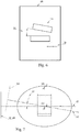
- FIG. 2 In a hypothetical perspective view, a virtual X-ray source 510 is shown, which generates a plurality of DRRs 520 with the aid of different projection directions 540.
- FIG. 3 shows the subject of the FIG. 2 in a hypothetical top view, wherein the determined uncorrected projection direction 532 is shown and the resulting uncorrected DRR 522 is indicated. It can also be seen that the uncorrected projection direction 532 is relative is tilted to a plane of symmetry of the object 300 'as well as relative to an object coordinate system 190 of the object 300'.
- the above-described step can be repeated for each area in order to be able to average the uncorrected projection direction 532 not just over one area, but over all areas.
- the uncorrected projection direction 532 determined with respect to the 3D model 400 'or with respect to the 3D objects 300' corresponds to the real projection direction which was used in the generation of the X-ray image, the real projection direction being oriented orthogonal to the recording plane 110 of the X-ray exposure 100.
- the geometry description is in the form of discrete area or volume elements. This model can be adjusted to the patient's actual morphology, regardless of the previous steps. For this purpose, the radiograph 100 is already sufficient for many applications. If there are further X-ray images 100 from other projection directions, these can also be used to adapt the mathematical geometry descriptions and to improve the imaging accuracy of the 3D objects 300 '.
- a patient-specific 3D model 400 'with patient-specific 3D objects 300' on the basis of statistical shape models and X-ray images is eg by Zheng et. al. in "Scaled, patient-specific 3D vertebral model reconstruction based on 2D lateral fluoroscopy", Int J CARS (2011) 6: 351-366 described and not essential to the invention.
- the method according to the invention is also suitable.
- the (possibly segmented) 3D model 400 ' is iteratively adapted via an affine transformation of the 3D objects 300' with the 2D-3D registration described above.
- the projection direction is not varied, but the position and orientation of the 3D objects 300 'are varied until the DRR generated after each change matches the X-ray image 100 in the best possible way.
- constraints may be entered via an interface, e.g.
- the defined sections or the entire X-ray image 100 of the objects 300 and the DRR for the uncorrected alignment 522 have the greatest possible match.
- the 3D objects 300 ' are thus arranged correctly within the 3D model 400' to one another and to the receiving plane 110.
- these X-ray images 100 are suitable for the particularly precise transformation and arrangement of the 3D objects 300 'in the 3D model 400' according to the previously described method.
- this plane may be a plane of the volume coordinate system (180) (VCS) of the 3D model 400 '(cf. FIG. 3 ).
- VCS volume coordinate system
- 3D model 400 'or 3D object 300' already have an optimal and reproducible orientation, for example, if the 3D model 400 'was generated from an MRI or CRT recording on a recumbent patient, which in This case is already almost optimally and reproducibly aligned for many measurement tasks.
- An advantageous embodiment is the automatic determination of the output level 600 or a measurement coordinate system 610 corresponding to the output level based on the definition of the object coordinate system 190 (OCS) or the object level 192 (cf. Figures 3 and 4 ).
- the object coordinate system 190 or the object level 192 is first determined for this purpose with the aid of the method according to the invention.
- Exemplary object levels 192 of the 3D objects 300 'within the 3D model 400' are shown in FIG FIG. 4 shown.
- the determination can advantageously take place by an evaluation of the gray value information of the 3D objects 300 '.
- a definition based on the actual position and position of the relevant 3D objects 300 ' is possible, in particular in the case of an asymmetrical arrangement of internal organs or bones.
- the selection of the voxels which serve to determine the object plane 192 or the object coordinate system 190 can be restricted manually or programmatically for this purpose. Depending on the structure to be identified, this can be achieved via one or more of the following methods: a) limitation of the permissible gray value range of the voxels; b) defining one or more selection regions via the radiograph 100; c) via methods of machine learning (neural networks); d) Definition of one or more cutting planes via the X-ray image 100 or e) via the 3D model 400 '.
- the selection of the regions or cutting planes is to be done manually, this is preferably done in the still uncorrected X-ray image 100, whereby the selection is projected via the uncorrected projection direction 532 into the 3D model 400 'and only the voxels are selected which are left by the cutting plane, selections, grayscale, and other constraints. This selection can be made manually by the operator or programmatically.
- Points, lines, ellipses, planes or other analytically describable contours, summarized reference objects are suitable for defining the object plane 192 or the object coordinate system 190.
- the position and shape of the reference objects within the 3D model 400 ' can be in particular I) by center or ( Area-) focus considerations; II) regression methods such as minimizing the squares of voxels to the reference objects; III) by symmetry considerations or IV) by trained neural networks in conjunction with two- or three-dimensional geometry descriptions (e.g., AAM, ASM, SSM).
- the reference objects can also be arranged in templates which can be manually or automatically drawn onto the visible structures and adapted.
- the object coordinate system 190 or the object plane 192 of a single 3D object 300 or based on a plurality of 3D coordinates, if the measurement coordinate system or the output plane 600 is defined on the basis of the 3D objects 300 '.
- Objects 300 it may be advantageous to do this on the basis of the object coordinate system 190 or the object plane 192 of a single 3D object 300, or based on a plurality of 3D coordinates, if the measurement coordinate system or the output plane 600 is defined on the basis of the 3D objects 300 '.
- the position of the output plane 600 or of the measurement coordinate system is expediently defined by an averaging of the individual object planes 192 or object coordinate systems 190 of the individual 3D objects 300, for example by the respective bisectors between the direction vectors ,
- the measurement coordinate system or the output plane 600 is defined on the basis of both objects (eg by the symmetry axis of a superior and the center of an inferior vertebral body).
- the output plane 600 or the measurement coordinate system is the use of predefined nodes of a 3D mathematical model 300 ', e.g. an ASM, AAM or SSM.
- a 3D mathematical model 300 ' e.g. an ASM, AAM or SSM.
- the output layer 600 may be fully described by three characteristic points. If the points define both origin and two axes, even the definition of the output coordinate system with only three points is possible.
- the orientation of the corrected projection direction 536 is defined at the same time as the normal vector of the output plane 600 or by using the Z-axis of the measuring coordinate system.
- FIG. 5 illustrates the corrected projection direction (536) which is orthogonal to the object plane 192 of the 3D object 300 'and which provides a corrected DRR 524 in the output plane 600.
- the tilt as the difference between the orientation of the X-ray 100 and the corrected output level 600 can be determined.
- This tilting results from the deviation between the corrected projection direction 536 and the previously determined uncorrected projection direction 532.
- the process of determining a deviation between the projection directions 536 and 532 is shown in FIG FIG. 7 illustrated.
- the deviation can be measured in the form of a difference angle 539.
- the surveying module according to the invention can be designed to determine the deviation.
- Advantage of variant b) is the always vertical or uniform image of the structures to be examined, which facilitates the manual or automatic placement of landmarks.
- An automatic placement of landmarks can preferably be done by means of the previously described methods for defining the object coordinate system.
- the X-ray image must be taken 100 and the corrected DRR 524 are calibrated to a pixel / unit scale. This can be done using a visible on the X-ray 100 calibration object with known dimensions, or by transfer of the usually known scale of the 3D model (voxel / unit length). If the 3D model consists of an ASM or SSM, the size of the model is always one of the highly variable vectors. In this case, the calibration of the X-ray image, the corrected output level DRR 524 or the ASM / AAM / SSM must be based on a calibration object of known dimensions visible on the X-ray 100. For lower accuracy requirements, one may resort to statistical morphological data of visible objects or the approximate scale of X-ray exposure 100 typically included in the X-ray file.
- Angle measurements usually do not require calibration to a linear scale, so this step can be omitted for measurement tasks that require only angle measurements.
- the actual measurement can then take place with the aid of the surveying module in a further step using the corrected projection direction 536 on the corrected DRR 524 in the output plane 600.
- This is in FIG. 6 illustrated. It can be seen from the figure that the border of the object in the corrected DRR 524 has no double edges, so that an exact measurement is possible. In particular, an exact angle measurement 140 and an exact distance measurement 150 can be performed.
- the knowledge of the tilt can be used together with one or more correction functions, to computationally correct the true lengths and angles between the measurement point definitions made in the uncorrected radiograph 100. This can also be carried out in this case by the surveying module according to the invention.
- 3D objects 300 it makes sense to carry out the measurements directly in the 3D model.
- distances and angles between predefined landmarks of the (possibly transformed and adapted) 3D objects 300 are used and the Euclidean distances or the distance components with respect to the measurement coordinate system or the output level 600 are indicated.
- This variant is particularly suitable for mathematically described 3D objects 300 based on the network nodes (for example, ASM / AAM / SSM).
- the measured values are e.g. stored in a database, a PACS or HIS system, or via a printable report.
Landscapes
- Health & Medical Sciences (AREA)
- Engineering & Computer Science (AREA)
- Life Sciences & Earth Sciences (AREA)
- Medical Informatics (AREA)
- Physics & Mathematics (AREA)
- Surgery (AREA)
- Public Health (AREA)
- Nuclear Medicine, Radiotherapy & Molecular Imaging (AREA)
- Pathology (AREA)
- Biomedical Technology (AREA)
- General Health & Medical Sciences (AREA)
- Heart & Thoracic Surgery (AREA)
- Molecular Biology (AREA)
- Animal Behavior & Ethology (AREA)
- Veterinary Medicine (AREA)
- Biophysics (AREA)
- High Energy & Nuclear Physics (AREA)
- Radiology & Medical Imaging (AREA)
- Optics & Photonics (AREA)
- Computer Vision & Pattern Recognition (AREA)
- Theoretical Computer Science (AREA)
- General Physics & Mathematics (AREA)
- Oral & Maxillofacial Surgery (AREA)
- Pulmonology (AREA)
- Physiology (AREA)
- Human Computer Interaction (AREA)
- Databases & Information Systems (AREA)
- Epidemiology (AREA)
- Primary Health Care (AREA)
- Data Mining & Analysis (AREA)
- Apparatus For Radiation Diagnosis (AREA)
- Image Processing (AREA)
- Geometry (AREA)
Applications Claiming Priority (1)
| Application Number | Priority Date | Filing Date | Title |
|---|---|---|---|
| DE102017201164.5A DE102017201164B3 (de) | 2017-01-25 | 2017-01-25 | Verfahren zur Vermessung einer Röntgenaufnahme eines medizinischen Untersuchungsbereichs nebst zugehöriger Vorrichtung und Computerprogramm |
Publications (3)
| Publication Number | Publication Date |
|---|---|
| EP3355268A1 true EP3355268A1 (fr) | 2018-08-01 |
| EP3355268C0 EP3355268C0 (fr) | 2023-07-26 |
| EP3355268B1 EP3355268B1 (fr) | 2023-07-26 |
Family
ID=60782952
Family Applications (1)
| Application Number | Title | Priority Date | Filing Date |
|---|---|---|---|
| EP18153407.4A Active EP3355268B1 (fr) | 2017-01-25 | 2018-01-25 | Procédé, dispositif de calcul et système de mesure d'une radiographie d'une zone d'examen médicale |
Country Status (4)
| Country | Link |
|---|---|
| US (1) | US10617381B2 (fr) |
| EP (1) | EP3355268B1 (fr) |
| CA (1) | CA2992858A1 (fr) |
| DE (1) | DE102017201164B3 (fr) |
Families Citing this family (7)
| Publication number | Priority date | Publication date | Assignee | Title |
|---|---|---|---|---|
| US11227385B2 (en) * | 2018-08-08 | 2022-01-18 | Loyola University Chicago | Methods of classifying and/or determining orientations of objects using two-dimensional images |
| LU100907B1 (en) * | 2018-08-23 | 2020-02-24 | Metamorphosis Gmbh I G | Determination of imaging direction based on a 2d projection image |
| US12109059B2 (en) * | 2020-05-19 | 2024-10-08 | Konica Minolta, Inc. | Dynamic analysis system, correction apparatus, storage medium, and dynamic imaging apparatus |
| CN112308764A (zh) * | 2020-10-12 | 2021-02-02 | 杭州三坛医疗科技有限公司 | 图像配准方法及装置 |
| DE102020128288A1 (de) * | 2020-10-28 | 2022-04-28 | Volume Graphics Gmbh | Computerimplementiertes Verfahren zur Ermittlung mindestens eines für eine Auswertung von Messdaten benötigten geometrischen Parameters |
| CN112348857B (zh) * | 2020-11-06 | 2024-10-15 | 苏州雷泰医疗科技有限公司 | 一种基于深度学习的放射治疗摆位偏移计算方法及系统 |
| WO2022099068A1 (fr) * | 2020-11-06 | 2022-05-12 | Materialise Nv | Système et procédés pour l'étalonnage d'images radiographiques |
Family Cites Families (7)
| Publication number | Priority date | Publication date | Assignee | Title |
|---|---|---|---|---|
| US6470207B1 (en) * | 1999-03-23 | 2002-10-22 | Surgical Navigation Technologies, Inc. | Navigational guidance via computer-assisted fluoroscopic imaging |
| DE102009008115B4 (de) * | 2009-02-09 | 2012-05-24 | Siemens Aktiengesellschaft | Verfahren und Vorrichtung zur Erzeugung eines digital rekonstruierten 2-D-Bildes aus einem 3-D-Bilddatensatz |
| WO2013166299A1 (fr) * | 2012-05-03 | 2013-11-07 | University Of Pittsburgh - Of The Commonwealth System Of Higher Education | Algorithmes intelligents de suivi du mouvement squelettique tridimensionnel à partir de séquences d'images radiographiques |
| EP2884897A1 (fr) * | 2012-08-20 | 2015-06-24 | orangedental GmbH & Co. KG | Caractérisation géométrique et étalonnage d'appareil de tomographie assistée par ordinateur à faisceau conique |
| DE102012217613A1 (de) * | 2012-09-27 | 2014-03-27 | Siemens Aktiengesellschaft | Verfahren zur Reduzierung von Artefakten bei der Rekonstruktion von Bilddatensätzen aus Projektionsbildern |
| KR20160010221A (ko) * | 2014-07-18 | 2016-01-27 | 삼성전자주식회사 | 의료 영상 촬영 장치 및 그에 따른 영상 처리 방법 |
| DE102016215831A1 (de) * | 2016-08-23 | 2018-03-01 | Siemens Healthcare Gmbh | Automatische Generierung synthetischer Projektionen |
-
2017
- 2017-01-25 DE DE102017201164.5A patent/DE102017201164B3/de active Active
-
2018
- 2018-01-25 CA CA2992858A patent/CA2992858A1/fr active Pending
- 2018-01-25 EP EP18153407.4A patent/EP3355268B1/fr active Active
- 2018-01-25 US US15/880,021 patent/US10617381B2/en active Active
Non-Patent Citations (1)
| Title |
|---|
| ZHENG G ET AL: "HipMatch: An object-oriented cross-platform program for accurate determination of cup orientation using 2D-3D registration of single standard X-ray radiograph and a CT volume", COMPUTER METHODS AND PROGRAMS IN BIOMEDICINE, ELSEVIER, AMSTERDAM, NL, vol. 95, no. 3, 1 September 2009 (2009-09-01), pages 236 - 248, XP026250765, ISSN: 0169-2607, [retrieved on 20090327], DOI: 10.1016/J.CMPB.2009.02.009 * |
Also Published As
| Publication number | Publication date |
|---|---|
| CA2992858A1 (fr) | 2018-07-25 |
| EP3355268C0 (fr) | 2023-07-26 |
| EP3355268B1 (fr) | 2023-07-26 |
| US20180206812A1 (en) | 2018-07-26 |
| DE102017201164B3 (de) | 2018-01-18 |
| US10617381B2 (en) | 2020-04-14 |
Similar Documents
| Publication | Publication Date | Title |
|---|---|---|
| EP3355268B1 (fr) | Procédé, dispositif de calcul et système de mesure d'une radiographie d'une zone d'examen médicale | |
| DE602004005341T2 (de) | Durchstrahlungsabbildungsverfahren für dreidimensionale rekonstruktion, vorrichtung und computersoftware zum durchführen des verfahrens | |
| DE69022063T2 (de) | Lokal angreifendes interaktives system innerhalb einer nichthomogenen struktur. | |
| EP1894538B1 (fr) | Procédé et appareil pour la détermination de la position des plans pelviens | |
| DE112016005720T5 (de) | 3D-Visualisierung während Chirurgie mit verringerter Strahlenbelastung | |
| DE102004056095A1 (de) | Verfahren zur Registrierung eines zur digitalen Subtraktionsangiographie verwendeten Bildes | |
| DE10357206B4 (de) | Verfahren und Bildbearbeitungssystem zur Segmentierung von Schnittbilddaten | |
| DE112004002435B4 (de) | Bestimmung von patientenbezogenen Informationen zur Position und Orientierung von MR-Bildern durch Individualisierung eines Körpermodells | |
| EP3389496B1 (fr) | Procédé pour calibrer un cliché radiographique | |
| DE10322738A1 (de) | Verfahren zur markerlosen automatischen Fusion von 2D-Fluoro-C-Bogen-Bildern mit präoperativen 3D-Bildern unter Verwendung eines intraoperativ gewonnenen 3D-Datensatzes | |
| US20100174673A1 (en) | Method for reconstruction of a three-dimensional model of a body structure | |
| DE102017214447B4 (de) | Planare Visualisierung von anatomischen Strukturen | |
| DE212012000054U1 (de) | Geräte, Aufbau, Schaltungen und Systeme zum Beurteilen, Einschätzen und/oder Bestimmen relativer Positionen, Ausrichtungen, Orientierungen und Rotationswinkel eines Teils eines Knochens und zwischen zwei oder mehreren Teilen eines oder mehrerer Knochen | |
| DE102013203399A1 (de) | Verfahren und Projektionsvorrichtung zur Markierung einer Oberfläche | |
| DE202022002940U1 (de) | Mittel zur Datenverarbeitung von zweidimensionalen Röntgenbildern zur Erstellung einer CT-ähnlichen Darstellung und virtueller Röntgenbilder in beliebigen Ansichten | |
| EP1052937B1 (fr) | Appareil d'examen aux rayons x | |
| DE102017223603B4 (de) | Verfahren zur Rekonstruktion eines dreidimensionalen, mit einer Biplan-Röntgeneinrichtung aufgenommenen Bilddatensatzes, Biplan-Röntgeneinrichtung, Computerprogramm und elektronisch lesbarer Datenträger | |
| EP2164042B1 (fr) | Procédé de vérification de la position relative de structures osseuses | |
| EP3626173A1 (fr) | Procédé de correction de déplacement d'un ensemble de données d'image tridimensionnel reconstruit, dispositif à rayons x biplan, programme informatique et support de données lisible électroniquement | |
| DE102016215831A1 (de) | Automatische Generierung synthetischer Projektionen | |
| DE102010013498B4 (de) | Verfahren zum Ermitteln von dreidimensionalen Volumendaten, Bildgebungsvorrichtung und Datenträger | |
| EP2241253B1 (fr) | Procédé destiné à compléter un ensemble de données d'images médicales | |
| DE102013200329B4 (de) | Verfahren und Vorrichtung zur Dejustagekorrektur für Bildgebungsverfahren | |
| DE10001709A1 (de) | Verfahren und Anordnung zur Erstellung von Röntgenbildern | |
| DE102006007255A1 (de) | Verfahren und Vorrichtung zur Bestimmung geometrischer Parameter für Bilderzeugung |
Legal Events
| Date | Code | Title | Description |
|---|---|---|---|
| PUAI | Public reference made under article 153(3) epc to a published international application that has entered the european phase |
Free format text: ORIGINAL CODE: 0009012 |
|
| STAA | Information on the status of an ep patent application or granted ep patent |
Free format text: STATUS: THE APPLICATION HAS BEEN PUBLISHED |
|
| AK | Designated contracting states |
Kind code of ref document: A1 Designated state(s): AL AT BE BG CH CY CZ DE DK EE ES FI FR GB GR HR HU IE IS IT LI LT LU LV MC MK MT NL NO PL PT RO RS SE SI SK SM TR |
|
| AX | Request for extension of the european patent |
Extension state: BA ME |
|
| STAA | Information on the status of an ep patent application or granted ep patent |
Free format text: STATUS: REQUEST FOR EXAMINATION WAS MADE |
|
| 17P | Request for examination filed |
Effective date: 20190128 |
|
| RBV | Designated contracting states (corrected) |
Designated state(s): AL AT BE BG CH CY CZ DE DK EE ES FI FR GB GR HR HU IE IS IT LI LT LU LV MC MK MT NL NO PL PT RO RS SE SI SK SM TR |
|
| STAA | Information on the status of an ep patent application or granted ep patent |
Free format text: STATUS: EXAMINATION IS IN PROGRESS |
|
| STAA | Information on the status of an ep patent application or granted ep patent |
Free format text: STATUS: EXAMINATION IS IN PROGRESS |
|
| 17Q | First examination report despatched |
Effective date: 20201102 |
|
| STAA | Information on the status of an ep patent application or granted ep patent |
Free format text: STATUS: EXAMINATION IS IN PROGRESS |
|
| GRAP | Despatch of communication of intention to grant a patent |
Free format text: ORIGINAL CODE: EPIDOSNIGR1 |
|
| STAA | Information on the status of an ep patent application or granted ep patent |
Free format text: STATUS: GRANT OF PATENT IS INTENDED |
|
| INTG | Intention to grant announced |
Effective date: 20230123 |
|
| GRAS | Grant fee paid |
Free format text: ORIGINAL CODE: EPIDOSNIGR3 |
|
| GRAA | (expected) grant |
Free format text: ORIGINAL CODE: 0009210 |
|
| STAA | Information on the status of an ep patent application or granted ep patent |
Free format text: STATUS: THE PATENT HAS BEEN GRANTED |
|
| AK | Designated contracting states |
Kind code of ref document: B1 Designated state(s): AL AT BE BG CH CY CZ DE DK EE ES FI FR GB GR HR HU IE IS IT LI LT LU LV MC MK MT NL NO PL PT RO RS SE SI SK SM TR |
|
| REG | Reference to a national code |
Ref country code: CH Ref legal event code: EP |
|
| REG | Reference to a national code |
Ref country code: IE Ref legal event code: FG4D Free format text: LANGUAGE OF EP DOCUMENT: GERMAN |
|
| REG | Reference to a national code |
Ref country code: DE Ref legal event code: R096 Ref document number: 502018012767 Country of ref document: DE |
|
| U01 | Request for unitary effect filed |
Effective date: 20230823 |
|
| RAP4 | Party data changed (patent owner data changed or rights of a patent transferred) |
Owner name: RAYLYTIC GMBH |
|
| REG | Reference to a national code |
Ref country code: LT Ref legal event code: MG9D |
|
| REG | Reference to a national code |
Ref country code: NL Ref legal event code: MP Effective date: 20230726 |
|
| U07 | Unitary effect registered |
Designated state(s): AT BE BG DE DK EE FI FR IT LT LU LV MT NL PT SE SI Effective date: 20231030 |
|
| PG25 | Lapsed in a contracting state [announced via postgrant information from national office to epo] |
Ref country code: GR Free format text: LAPSE BECAUSE OF FAILURE TO SUBMIT A TRANSLATION OF THE DESCRIPTION OR TO PAY THE FEE WITHIN THE PRESCRIBED TIME-LIMIT Effective date: 20231027 |
|
| PG25 | Lapsed in a contracting state [announced via postgrant information from national office to epo] |
Ref country code: IS Free format text: LAPSE BECAUSE OF FAILURE TO SUBMIT A TRANSLATION OF THE DESCRIPTION OR TO PAY THE FEE WITHIN THE PRESCRIBED TIME-LIMIT Effective date: 20231126 |
|
| PG25 | Lapsed in a contracting state [announced via postgrant information from national office to epo] |
Ref country code: RS Free format text: LAPSE BECAUSE OF FAILURE TO SUBMIT A TRANSLATION OF THE DESCRIPTION OR TO PAY THE FEE WITHIN THE PRESCRIBED TIME-LIMIT Effective date: 20230726 Ref country code: NO Free format text: LAPSE BECAUSE OF FAILURE TO SUBMIT A TRANSLATION OF THE DESCRIPTION OR TO PAY THE FEE WITHIN THE PRESCRIBED TIME-LIMIT Effective date: 20231026 Ref country code: IS Free format text: LAPSE BECAUSE OF FAILURE TO SUBMIT A TRANSLATION OF THE DESCRIPTION OR TO PAY THE FEE WITHIN THE PRESCRIBED TIME-LIMIT Effective date: 20231126 Ref country code: HR Free format text: LAPSE BECAUSE OF FAILURE TO SUBMIT A TRANSLATION OF THE DESCRIPTION OR TO PAY THE FEE WITHIN THE PRESCRIBED TIME-LIMIT Effective date: 20230726 Ref country code: GR Free format text: LAPSE BECAUSE OF FAILURE TO SUBMIT A TRANSLATION OF THE DESCRIPTION OR TO PAY THE FEE WITHIN THE PRESCRIBED TIME-LIMIT Effective date: 20231027 |
|
| U20 | Renewal fee paid [unitary effect] |
Year of fee payment: 7 Effective date: 20240124 |
|
| PG25 | Lapsed in a contracting state [announced via postgrant information from national office to epo] |
Ref country code: PL Free format text: LAPSE BECAUSE OF FAILURE TO SUBMIT A TRANSLATION OF THE DESCRIPTION OR TO PAY THE FEE WITHIN THE PRESCRIBED TIME-LIMIT Effective date: 20230726 |
|
| PG25 | Lapsed in a contracting state [announced via postgrant information from national office to epo] |
Ref country code: ES Free format text: LAPSE BECAUSE OF FAILURE TO SUBMIT A TRANSLATION OF THE DESCRIPTION OR TO PAY THE FEE WITHIN THE PRESCRIBED TIME-LIMIT Effective date: 20230726 |
|
| REG | Reference to a national code |
Ref country code: DE Ref legal event code: R097 Ref document number: 502018012767 Country of ref document: DE |
|
| PG25 | Lapsed in a contracting state [announced via postgrant information from national office to epo] |
Ref country code: SM Free format text: LAPSE BECAUSE OF FAILURE TO SUBMIT A TRANSLATION OF THE DESCRIPTION OR TO PAY THE FEE WITHIN THE PRESCRIBED TIME-LIMIT Effective date: 20230726 Ref country code: RO Free format text: LAPSE BECAUSE OF FAILURE TO SUBMIT A TRANSLATION OF THE DESCRIPTION OR TO PAY THE FEE WITHIN THE PRESCRIBED TIME-LIMIT Effective date: 20230726 Ref country code: ES Free format text: LAPSE BECAUSE OF FAILURE TO SUBMIT A TRANSLATION OF THE DESCRIPTION OR TO PAY THE FEE WITHIN THE PRESCRIBED TIME-LIMIT Effective date: 20230726 Ref country code: CZ Free format text: LAPSE BECAUSE OF FAILURE TO SUBMIT A TRANSLATION OF THE DESCRIPTION OR TO PAY THE FEE WITHIN THE PRESCRIBED TIME-LIMIT Effective date: 20230726 Ref country code: SK Free format text: LAPSE BECAUSE OF FAILURE TO SUBMIT A TRANSLATION OF THE DESCRIPTION OR TO PAY THE FEE WITHIN THE PRESCRIBED TIME-LIMIT Effective date: 20230726 |
|
| PLBE | No opposition filed within time limit |
Free format text: ORIGINAL CODE: 0009261 |
|
| STAA | Information on the status of an ep patent application or granted ep patent |
Free format text: STATUS: NO OPPOSITION FILED WITHIN TIME LIMIT |
|
| 26N | No opposition filed |
Effective date: 20240429 |
|
| PG25 | Lapsed in a contracting state [announced via postgrant information from national office to epo] |
Ref country code: MC Free format text: LAPSE BECAUSE OF FAILURE TO SUBMIT A TRANSLATION OF THE DESCRIPTION OR TO PAY THE FEE WITHIN THE PRESCRIBED TIME-LIMIT Effective date: 20230726 |
|
| PG25 | Lapsed in a contracting state [announced via postgrant information from national office to epo] |
Ref country code: MC Free format text: LAPSE BECAUSE OF FAILURE TO SUBMIT A TRANSLATION OF THE DESCRIPTION OR TO PAY THE FEE WITHIN THE PRESCRIBED TIME-LIMIT Effective date: 20230726 |
|
| REG | Reference to a national code |
Ref country code: CH Ref legal event code: PL |
|
| GBPC | Gb: european patent ceased through non-payment of renewal fee |
Effective date: 20240125 |
|
| PG25 | Lapsed in a contracting state [announced via postgrant information from national office to epo] |
Ref country code: GB Free format text: LAPSE BECAUSE OF NON-PAYMENT OF DUE FEES Effective date: 20240125 |