EP3353582B1 - Optische folie und leuchte mit einer solchen - Google Patents
Optische folie und leuchte mit einer solchen Download PDFInfo
- Publication number
- EP3353582B1 EP3353582B1 EP16775592.5A EP16775592A EP3353582B1 EP 3353582 B1 EP3353582 B1 EP 3353582B1 EP 16775592 A EP16775592 A EP 16775592A EP 3353582 B1 EP3353582 B1 EP 3353582B1
- Authority
- EP
- European Patent Office
- Prior art keywords
- optical film
- elevations
- light
- range
- microstructure
- Prior art date
- Legal status (The legal status is an assumption and is not a legal conclusion. Google has not performed a legal analysis and makes no representation as to the accuracy of the status listed.)
- Active
Links
Images

Classifications
-
- F—MECHANICAL ENGINEERING; LIGHTING; HEATING; WEAPONS; BLASTING
- F21—LIGHTING
- F21V—FUNCTIONAL FEATURES OR DETAILS OF LIGHTING DEVICES OR SYSTEMS THEREOF; STRUCTURAL COMBINATIONS OF LIGHTING DEVICES WITH OTHER ARTICLES, NOT OTHERWISE PROVIDED FOR
- F21V5/00—Refractors for light sources
- F21V5/002—Refractors for light sources using microoptical elements for redirecting or diffusing light
- F21V5/005—Refractors for light sources using microoptical elements for redirecting or diffusing light using microprisms
-
- F—MECHANICAL ENGINEERING; LIGHTING; HEATING; WEAPONS; BLASTING
- F21—LIGHTING
- F21V—FUNCTIONAL FEATURES OR DETAILS OF LIGHTING DEVICES OR SYSTEMS THEREOF; STRUCTURAL COMBINATIONS OF LIGHTING DEVICES WITH OTHER ARTICLES, NOT OTHERWISE PROVIDED FOR
- F21V5/00—Refractors for light sources
- F21V5/002—Refractors for light sources using microoptical elements for redirecting or diffusing light
-
- F—MECHANICAL ENGINEERING; LIGHTING; HEATING; WEAPONS; BLASTING
- F21—LIGHTING
- F21S—NON-PORTABLE LIGHTING DEVICES; SYSTEMS THEREOF; VEHICLE LIGHTING DEVICES SPECIALLY ADAPTED FOR VEHICLE EXTERIORS
- F21S8/00—Lighting devices intended for fixed installation
- F21S8/04—Lighting devices intended for fixed installation intended only for mounting on a ceiling or the like overhead structures
-
- F—MECHANICAL ENGINEERING; LIGHTING; HEATING; WEAPONS; BLASTING
- F21—LIGHTING
- F21V—FUNCTIONAL FEATURES OR DETAILS OF LIGHTING DEVICES OR SYSTEMS THEREOF; STRUCTURAL COMBINATIONS OF LIGHTING DEVICES WITH OTHER ARTICLES, NOT OTHERWISE PROVIDED FOR
- F21V3/00—Globes; Bowls; Cover glasses
- F21V3/04—Globes; Bowls; Cover glasses characterised by materials, surface treatments or coatings
- F21V3/06—Globes; Bowls; Cover glasses characterised by materials, surface treatments or coatings characterised by the material
- F21V3/062—Globes; Bowls; Cover glasses characterised by materials, surface treatments or coatings characterised by the material the material being plastics
- F21V3/0625—Globes; Bowls; Cover glasses characterised by materials, surface treatments or coatings characterised by the material the material being plastics the material diffusing light, e.g. translucent plastics
-
- G—PHYSICS
- G02—OPTICS
- G02B—OPTICAL ELEMENTS, SYSTEMS OR APPARATUS
- G02B5/00—Optical elements other than lenses
- G02B5/02—Diffusing elements; Afocal elements
- G02B5/0205—Diffusing elements; Afocal elements characterised by the diffusing properties
- G02B5/021—Diffusing elements; Afocal elements characterised by the diffusing properties the diffusion taking place at the element's surface, e.g. by means of surface roughening or microprismatic structures
-
- G—PHYSICS
- G02—OPTICS
- G02B—OPTICAL ELEMENTS, SYSTEMS OR APPARATUS
- G02B5/00—Optical elements other than lenses
- G02B5/02—Diffusing elements; Afocal elements
- G02B5/0273—Diffusing elements; Afocal elements characterized by the use
- G02B5/0278—Diffusing elements; Afocal elements characterized by the use used in transmission
-
- G—PHYSICS
- G02—OPTICS
- G02B—OPTICAL ELEMENTS, SYSTEMS OR APPARATUS
- G02B5/00—Optical elements other than lenses
- G02B5/04—Prisms
- G02B5/045—Prism arrays
-
- F—MECHANICAL ENGINEERING; LIGHTING; HEATING; WEAPONS; BLASTING
- F21—LIGHTING
- F21Y—INDEXING SCHEME ASSOCIATED WITH SUBCLASSES F21K, F21L, F21S and F21V, RELATING TO THE FORM OR THE KIND OF THE LIGHT SOURCES OR OF THE COLOUR OF THE LIGHT EMITTED
- F21Y2115/00—Light-generating elements of semiconductor light sources
- F21Y2115/10—Light-emitting diodes [LED]
- F21Y2115/15—Organic light-emitting diodes [OLED]
Definitions
- the invention relates to an optical film according to the preamble of independent claim 1 and a lamp with such an optical film.
- Optical foils made of a light-transmissive material with a surface and an optical microstructure that includes a large number of elevations, the elevations of the microstructure protruding from a reference plane that is parallel to the surface, can result in an application-specific and efficient shaping of emitted or radiated light be used.
- the optics cover one or more lamps in such a way that the light emitted by the lamp penetrates the optics and is adjusted by it.
- adjustment may include directing the light, dimming the light, coloring the light, diffusing the light, or the like.
- such optics are manufactured by molding the structures directly in a solid substrate of the optic.
- the structures can be ground into the substrate of the optics.
- such optics with structures in the solid substrate are relatively expensive to manufacture and relatively difficult to shape, especially in the case of large lamps.
- Another way of providing optics improved with respect to the disadvantages of the above optics is to combine a light-transmissive substrate with a light or To provide luminous properties adjusting optical film.
- the substrate can be a transparent solid plastic, glass or the like.
- By providing the substrate with an optical film it can be equipped with application-related properties in an efficient manner.
- a desired optic can also be produced in this way with relatively little effort.
- films are known which are applied to a substrate, for example glued or placed thereon.
- the foils themselves can already be adhesive on one side or the foils can be attached to the substrate with an additional adhesive in a manufacturing step of the optics.
- Such foils are partly intended to scatter or attenuate the light.
- the film is made of a light transmissive material and has a surface and an optical microstructure.
- the optical microstructure consists of a large number of elevations that protrude from the surface.
- the surveys of the microstructure of the film are according to the teaching of WO 2012/141899 A1 designed as cones, prisms or pyramids, the sides of which have a random and varying base angle. This base angle corresponds to the angle between a direction orthogonal to the surface of the film and the associated side of the bump. It should have a random value between 10° and 60°.
- the microstructure is intended to help the optics fitted with the film to reduce glare from penetrating light by directing the light from the side of the elevations of the microstructure.
- the random base angle of the elevations is intended to ensure that the light source is less visible or no longer visible at all, which can be a concern with LED light sources in particular.
- a disadvantage of foils of the type described above is that, particularly when they are used in an elongate lamp or linear lamp, satisfactory glare control of the emitted light is not achieved for many purposes.
- LLK light distribution curve
- the formation of the emitted light cone in the case of light sources that emit non-directional light, such as organic light-emitting diodes (OLED) cannot be sufficiently efficient and precise.
- an object of the present invention to propose an optical film or a lamp that reduces glare with a relatively high level of efficiency and that can be used efficiently with non-directional or partially directional light sources.
- An optical film made of a light-transmitting material comprises a surface and an optical microstructure with a large number of elevations.
- the elevations of the microstructure protrude from a reference plane that is parallel to the surface.
- the elevations of the microstructure each have a flank section which is adjacent to the reference plane and describes a uniform angle with the reference plane.
- the uniform angle is in a range from about 33° to about 42° or in a range from about 35° to about 40°.
- the surface of the optical film can be the side of the film on which the bumps are located. Or it can be the opposite side of the optical film, which is typically planar. In one embodiment, the surface may be at the level of the peaks of the projections.
- the reference plane is parallel and spaced from the surface. In another embodiment, the surface can also lie in the reference plane. The surface is then parallel to the reference plane but not at a distance from it.
- the surface and also the reference plane typically extend more or less at right angles to a main or central emission direction of a lamp in which the optical film is used. In many applications, such as ceiling lights or floor lamps, the main or central emission direction is vertical and the surface or the The reference plane is accordingly horizontal. The elevations typically protrude from the surface.
- the term "translucent" can refer in particular to an attenuated or undamped transparency of the light generated by means of an illuminant of a lamp.
- the term "uniform" in relation to the flank portion of one of the ridges refers to the ridge making a single, substantially equal angle with the reference plane circumferentially. For example, there may be tolerance deviations due to manufacturing reasons, which are still considered uniform in this sense. For example, such tolerance deviations can occur to an extent of up to approximately 1°.
- the term "glare control" can refer to the fact that for certain applications of luminaires, this means that for all beam angles that are greater than 65°, measured against the vertical pointing downwards, the emitted light must not exceed a luminance of 3,000 candelas per square meter (cd/m 2 ).
- the ability to reduce glare can be recorded or specified as anti-glare performance (AP).
- the AP indicates how much luminous flux (lumen) can be emitted from a given reference area without glare in the sense of the standard mentioned above. The higher the AP, the more degrees of freedom can result in the design of an associated light and the more miniaturized or more compact the light could be built.
- optical film within the meaning of the invention can refer to a relatively large, thin structure. Such structures typically have a much larger surface area in relation to their thickness. For example, such structures can have a thickness of less than 1 millimeter (mm), and typically less than 0.1 mm.
- the associated surface can be virtually any size. For example, it can be at least 5 centimeters (cm) by 5 cm.
- the optical film has a surface area to thickness ratio of at least about 25,000, or typically at least about 250,000.
- Optical foils can be made of different materials.
- films made of plastic can be produced efficiently and flexibly.
- Such films are preferably made from a material with a refractive index in a range from about 1.3 to about 1.7, such as a plastic and in particular a polycarbonate.
- Alternative plastics can be, for example, polyethylene or polymethyl methacrylate.
- the term "refractive index" means an optical material property that indicates the factor by which the wavelength and the phase velocity of the light in the material are smaller than in a vacuum.
- films made of such materials enable the effects and advantages of the invention to be achieved in a particularly efficient manner.
- Films made of plastic or polycarbonate can be provided with microstructures of the type according to the invention in an efficient and precise manner.
- microstructures can be formed onto or into the plastic by means of laser ablation, hot stamping, ultraviolet casting, injection molding, compression molding or a generative process such as 3D printing.
- it can also be expedient to produce a master and to produce the film by duplication, for example using the roll-to-roll method.
- laser ablation, milling or micro-milling, electron beam processing or generative construction such as 3D printing can be used to produce the master with the microstructure.
- the optical film according to the invention can be manufactured comparatively easily and efficiently. It can also be used flexibly. For example, it can be relatively easily tailored to the shape of an associated optic or other component of a lamp. In addition, it can also adapt to the shape of the optics or luminaire, such as a curvature. Furthermore, it can also be relatively robust, which enables easy handling and a long service life.
- the optical film of the present invention further enables a luminaire to effectively achieve high glare control.
- the light emitted by the lamp also enables the light emitted by the lamp to be shaped effectively and precisely, in particular if the lamp has a non-directional or partially directional light source such as one or more organic light-emitting diodes (OLED).
- a preferred light distribution curve (LVK) can be generated via the uniform angle of the flank sections of the elevations in the specified areas.
- the emitted light can also be shaped asymmetrically or like wings.
- the film according to the invention can be advantageous from an aesthetic point of view, since the microstructures can only be perceived to a very limited extent or not at all with the naked eye. In this way, an unobtrusive, clean appearance can be achieved.
- the relatively strong anti-glare and light control of the film can therefore not appear aesthetically, but the film can appear optically as a simple diffuse film. This offers many possible applications, for example in architecturally integrated lighting. Different LDCs can also be realized with the same aesthetics.
- the film can also be used to prevent the "tilt image” that occurs with known optics with a macrostructure.
- “tilt image” can mean a perception of structures or geometries. In particular, this term can refer to the fact that the light-emitting surface image generated changes suddenly, ie abruptly and not smoothly, at a specific viewing angle.
- the elevations of the microstructure of the optical film are each designed as a cone or cone. Shapes of this type allow the elevations to be configured in a relatively simple geometric manner, each with clearly defined flank sections. This allows the uniform angles to be implemented relatively easily.
- a LVK can be precisely predetermined in this way.
- the elevations of the microstructure preferably have a hexagonal base area.
- base area can be understood in particular as meaning the cross section of the elevation at the height of the reference plane. Elevations with hexagonal bases can have a large or maximum loading of the optical film Facilitate surveys in an efficient manner. In addition, the proportion of zones of the optical film that do not have the intended light-shaping effect can also be minimized. As a result, the optical film can have a relatively high efficiency with regard to the light-shaping or light-directing effect.
- the elevations of the microstructure of the optical film have a rounded tip.
- the term “peak” can be understood to mean an area which faces away from the reference plane or is at a maximum distance from it.
- the peak of an elevation may be opposite to its base.
- Such a rounded tip can help to minimize or prevent undesirable color effects or rainbow effects. This can be achieved by reducing or avoiding angular shapes or transitions in the microstructure.
- the rounded tips of the elevations preferably each border on their flank sections.
- the elevations each comprise a base area corresponding, for example, to the hexagonal base area, which has a maximum diameter in a range from about 5 ⁇ m to about 250 ⁇ m or in a range from about 50 ⁇ m to about 200 ⁇ m or in a range from about 150 ⁇ m to about 190 ⁇ m.
- the elevations preferably each have a height that is in a range from about 5 ⁇ m to about 100 ⁇ m or in a range from about 20 ⁇ m to about 80 ⁇ m or in a range from about 30 ⁇ m to about 60 ⁇ m.
- the height can be defined by the distance between the base and the peak. Elevations dimensioned in this way as a microstructure make it possible for the optical film to produce a preferred effect and at the same time to be able to be produced relatively efficiently.
- the uniform angle may differ between individual bumps or between groups of bumps. This means that the angles mentioned are uniform per elevation but vary among the elevations. This can enable a flexible adjustment of an LVK.
- all elevations of the microstructure of the optical film preferably have the same uniform angle.
- the term "equal" in the context of the uniform angles may refer to all elevations having an identical uniform angle. Tolerance deviations can occur, for example, for manufacturing reasons occur that are still considered equal in this sense. For example, such tolerance deviations can have a value of up to approximately 1°.
- An optical film configured in this way enables a preferred or intended effect to be produced homogeneously in an efficient manner.
- a further aspect of the invention relates to a lamp with a light source and an optical film as described above.
- the light source With the light source, light can be emitted essentially in an undirected manner.
- the optical film covers the illuminant in a direction of emission of the lamp.
- the illuminant can be an OLED or an OLED field, for example. Or it can be a light-emitting diode equipped with light-scattering optics or a field of such light-emitting diodes.
- light-emitting diode can be understood synonymously with light-emitting diode or light-emitting diode (LED).
- LED light-emitting diode
- the light-emitting diodes can be configured, for example, as round, elliptical, square or rectangular. They can be attached to a circuit board, which can also be equipped with control electronics for operating the light-emitting diodes.
- board in this context may refer to a printed circuit board (PCB) that is a carrier for electronic components.
- PCB printed circuit board
- Printed circuit boards or circuit boards usually consist of an electrically insulating material with conductive connections (conductor tracks) adhering to it. Fiber-reinforced plastic is commonly used as the insulating material.
- the conductor tracks are usually etched from a thin layer of copper.
- the components are soldered on soldering surfaces (pads) or in soldering eyes. Larger components can also be attached to the circuit board with cable ties, glue or screw connections.
- non-directional in connection with the lighting means of the lamp can refer to the fact that light is not emitted in a predefined manner in a specific direction, but to a certain extent in different directions.
- Undirected light can also be referred to as diffuse light or include such.
- this term can be understood to mean that the light source emits light to a certain extent in a random or undetermined direction. This can also include a partially directed Be lights as long as there is a proportion of undirected light in the above sense.
- the optical film can be applied to a fixed part of the optics.
- the optical film can be placed on the fixed part or glued to it.
- the adhesive used also has a refractive index.
- an adhesive or an adhesive with a refractive index as close as possible to 1 is preferably used.
- the light is preferably designed as a linear light.
- it can have a series of OLEDs or LEDs as illuminants.
- the term “linear luminaire” can refer to an oblong luminaire, such as is often used today to illuminate indoor and outdoor spaces.
- the term “longitudinal” can refer to a linear, quasi-linear or curved shape. In any case, however, the lengthwise extent is greater than the widthwise extent.
- the linear luminaire or named parts thereof can be designed to be essentially straight in a cross section along a longitudinal direction.
- linear lights extend along a space or object on which they are placed. For example, they can be attached directly to walls, suspended, or attached to ceilings.
- the lamp can be stacked.
- the light source can be separated from the optical film by an air gap and thus form a stack.
- the optical sheet can be attached to the illuminant with an adhesive so that the illuminant, adhesive and optical sheet form a stack.
- Such a stacked construction enables a compact construction.
- the optical film is preferably arranged in the light fixture directly adjacent to the light source.
- the term "directly adjacent" can refer to the fact that the optical film is as close as technically reasonable or feasible to the illuminant.
- the optical film according to the invention and the light according to the invention can be advantageous or used, for example, in the following areas of application: Architectural lighting applications, theater lighting applications and general lighting applications.
- the areas of application also include underwater lighting applications, for example in swimming pools, fountains or spas, traffic lighting applications, vehicle lighting applications, medical lighting applications, for example in hospitals, office or school lighting applications, retail or shopping lighting applications and industrial lighting applications in general.
- the general lighting applications as listed above can be residential, commercial and industrial lighting applications.
- the following characteristics can be present: Light in the visible range with a wavelength of between 350mm and 850nm is used, the lighting is standardized and interchangeable, the lighting is designed according to the standard IEC/PAS 62717 "Performance requirements - LED modules for general lighting”. or the standard “IEC/PAS 62722 Performance requirements - LED luminaries for general lighting", the lights comprise intelligence such as sensors and communication cells to provide connected lighting, and/or the lights have a general lighting purpose and can be divided into the types divided into functional and decorative.
- the traffic lighting applications as listed above may be advanced lighting applications intended to offer services related to various types of transportation and traffic management. They can enable different users to be better informed and networks to be used more securely, coordinated and intelligently.
- traffic lighting applications in intelligent transport networks come in all types of transport.
- the EU Directive 2010/40/EU July 7, 2010 defines which information and communication technologies are used in ITS systems in areas such as road transport including infrastructure, vehicles and users as well as in traffic or mobility management and interfaces for other types of transport.
- the vehicle lighting applications as listed above can be any lighting applications that provide light inside and outside passenger, light and heavy duty vehicles.
- such applications may include: headlights and taillights, visibility, signal and identification lights, emergency warning devices, interior and convenience lighting including distribution lighting, and on-duty vehicles.
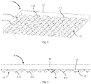
- the film 1 shows a schematic of an exemplary embodiment of an optical film 1 according to the invention.
- the film 1 is made, for example, from polycarbonate as the light-transmitting material. It comprises a flat base body 12 and a surface 13.
- the flat base body 12 is equipped with a microstructure 11 on the side of the surface 13, which comprises a multiplicity of quasi-hill-shaped or quasi-conical elevations 111.
- the elevations 111 have flank sections 112 which each merge into a rounded tip 113 . As a result, the flank sections 112 adjoin the associated rounded tips 113 .
- the elevations 111 are distributed uniformly and evenly over the surface 13 .
- the microstructure 11 can be formed in the polycarbonate by means of press molding, for example in a roll-to-roll process, or by means of laser ablation.
- the film 1 has a reference plane 15 corresponding to the surface 13, from which the elevations 111 of the microstructure 11 protrude.
- the flank sections 112 of the elevations 111 are straight from the side. They border on the reference plane 15 or emanate from it.
- the flank sections 112 and the reference plane 15 describe a uniform angle ⁇ , which is constant over the entire film 1 and the entire circumference of the individual elevations 111.
- the uniform angle ⁇ is 35°, with certain tolerance deviations being possible, for example for manufacturing reasons.
- the lamp 2 is designed as a ceiling lamp, which emits light in a direction of emission 24 vertically downwards.
- the lamp 2 includes a housing 22 in which a light source with an organic light-emitting diode (OLED light source) 21 is arranged.
- OLED light source 21 organic light-emitting diode
- the OLED illuminant 21 emits light non-directionally from its lower surface.
- the film 1 is also attached in the housing 22 parallel to the OLED illuminant 21 , with the microstructure 11 facing away from the OLED illuminant 21 .
- the film 1 completely covers the OLED illuminant 21 on its light-emitting lower surface or in the emission direction 24 .
- the housing 22 is closed off by transparent optics 23 at the bottom.
- the optics 23 covers the film 1 from the outside.
- the OLED lamp 21 emits its undirected light from below. This light penetrates the foil 1 and is directed and shaped by its microstructure 11 .
- the shape of the elevations 111 with the uniform angle ⁇ of 35° enables high glare reduction in an effective manner is reached.
- it also enables the light emitted by the lamp 2 to be shaped effectively and precisely, or a preferred light distribution curve (LVK) to be produced effectively and precisely.
- undesired rainbow effects can be minimized via the rounded tips 113 of the elevations 111 .
- the lamp 2 from below or from its optics 23 forth. It can be seen through the transparent optics 23 that the elevations 111 of the microstructure 11 of the film 1 have a hexagonal basic shape. Such a basic shape makes it possible for the film 1 to be densely or completely fitted with elevations 111 .
- the present disclosure also includes embodiments with any combination of features that are mentioned or shown above or below for different embodiments. It also includes individual features in the figures, even if they are shown there in connection with other features and/or are not mentioned above or below.
- the alternatives of embodiments described in the figures and the description and individual alternatives their features can also be excluded from the subject matter of the invention or from the disclosed objects.
- the disclosure includes embodiments that exclusively include the features described in the claims or in the exemplary embodiments, as well as those that include additional other features.
Landscapes
- Physics & Mathematics (AREA)
- Engineering & Computer Science (AREA)
- General Engineering & Computer Science (AREA)
- General Physics & Mathematics (AREA)
- Optics & Photonics (AREA)
- Optical Elements Other Than Lenses (AREA)
- Planar Illumination Modules (AREA)
- Electroluminescent Light Sources (AREA)
Applications Claiming Priority (2)
| Application Number | Priority Date | Filing Date | Title |
|---|---|---|---|
| CH001383/2015A CH711562B1 (de) | 2015-09-24 | 2015-09-24 | Optische Folie und Leuchte mit einer solchen. |
| PCT/EP2016/072599 WO2017050929A1 (de) | 2015-09-24 | 2016-09-22 | Optische folie und leuchte mit einer solchen |
Publications (2)
| Publication Number | Publication Date |
|---|---|
| EP3353582A1 EP3353582A1 (de) | 2018-08-01 |
| EP3353582B1 true EP3353582B1 (de) | 2022-03-30 |
Family
ID=54544861
Family Applications (1)
| Application Number | Title | Priority Date | Filing Date |
|---|---|---|---|
| EP16775592.5A Active EP3353582B1 (de) | 2015-09-24 | 2016-09-22 | Optische folie und leuchte mit einer solchen |
Country Status (10)
| Country | Link |
|---|---|
| US (1) | US11022272B2 (da) |
| EP (1) | EP3353582B1 (da) |
| KR (1) | KR102672028B1 (da) |
| CN (1) | CN108351439A (da) |
| AU (1) | AU2016328757B2 (da) |
| CH (1) | CH711562B1 (da) |
| DK (1) | DK3353582T3 (da) |
| ES (1) | ES2913274T3 (da) |
| PL (1) | PL3353582T3 (da) |
| WO (1) | WO2017050929A1 (da) |
Families Citing this family (3)
| Publication number | Priority date | Publication date | Assignee | Title |
|---|---|---|---|---|
| TWI661236B (zh) * | 2018-04-13 | 2019-06-01 | 采資新技股份有限公司 | 用於降低眩光之光罩光學元件 |
| EP3770491B1 (en) * | 2019-07-24 | 2025-05-21 | Regent Beleuchtungskörper AG | Lighting device |
| WO2024132501A1 (en) | 2022-12-21 | 2024-06-27 | Basf Coatings Gmbh | Transparent multi-layer system |
Citations (4)
| Publication number | Priority date | Publication date | Assignee | Title |
|---|---|---|---|---|
| US4497860A (en) * | 1978-12-18 | 1985-02-05 | Minnesota Mining And Manufacturing Company | Imageable prismatic array |
| WO1996023649A1 (en) * | 1995-02-03 | 1996-08-08 | Minnesota Mining And Manufacturing Company | Prevention of groove tip deformation in brightness enhancement film |
| WO2013116104A1 (en) * | 2012-01-31 | 2013-08-08 | 3M Innovative Properties Company | Light directing films and methods of making same |
| US20150153013A1 (en) * | 2013-11-29 | 2015-06-04 | Benq Materials Corporation | Light adjusting film |
Family Cites Families (18)
| Publication number | Priority date | Publication date | Assignee | Title |
|---|---|---|---|---|
| JP4506070B2 (ja) * | 2002-11-01 | 2010-07-21 | コニカミノルタホールディングス株式会社 | 防眩層の形成方法、防眩フィルムの製造方法及び防眩層形成用のインクジェット装置 |
| JP2007265783A (ja) * | 2006-03-28 | 2007-10-11 | Nippon Zeon Co Ltd | 直下型バックライト装置 |
| JP2009204900A (ja) * | 2008-02-28 | 2009-09-10 | Epson Toyocom Corp | 光学素子の反射防止構造、その反射防止構造を備えた光学素子および反射防止構造の加工方法 |
| CN101963678B (zh) * | 2009-07-21 | 2012-06-13 | 迎辉科技股份有限公司 | 增亮扩散膜 |
| KR101481181B1 (ko) * | 2009-07-29 | 2015-01-12 | 코오롱인더스트리 주식회사 | 집광형 광학 시트 |
| US8917447B2 (en) * | 2010-01-13 | 2014-12-23 | 3M Innovative Properties Company | Microreplicated film for attachment to autostereoscopic display components |
| US9086521B2 (en) | 2011-04-14 | 2015-07-21 | Bright View Technologies Corporation | Light transmissive structures and fabrication methods for controlling far-field light distribution |
| JP2013065521A (ja) * | 2011-09-20 | 2013-04-11 | Minebea Co Ltd | 配光制御部材及びそれを用いた照明装置 |
| TWI504949B (zh) * | 2011-10-27 | 2015-10-21 | Hon Hai Prec Ind Co Ltd | 導光板及發光裝置 |
| KR20130047334A (ko) * | 2011-10-31 | 2013-05-08 | 엘지이노텍 주식회사 | 조명 부재 및 이를 포함하는 조명 장치 |
| DE102012102986A1 (de) * | 2012-04-05 | 2013-10-10 | Siteco Beleuchtungstechnik Gmbh | Prismenplatte mit variierenden Flankenwinkeln |
| CN103728686A (zh) * | 2012-10-10 | 2014-04-16 | 奇菱科技股份有限公司 | 导光膜 |
| CN104110591A (zh) * | 2013-04-22 | 2014-10-22 | 展晶科技(深圳)有限公司 | 发光二极管灯具 |
| WO2015046439A1 (ja) * | 2013-09-26 | 2015-04-02 | 大日本印刷株式会社 | プリズムシート、面光源装置、映像源ユニット、及び液晶表示装置 |
| JP2016539354A (ja) * | 2013-10-03 | 2016-12-15 | スリーエム イノベイティブ プロパティズ カンパニー | 遠隔照明システム |
| KR20150111024A (ko) * | 2014-03-24 | 2015-10-05 | 삼성디스플레이 주식회사 | 백라이트 어셈블리 |
| US20150285959A1 (en) * | 2014-04-02 | 2015-10-08 | Nebula Energy Inc. | Solar radiation concentrators, methods of concentrating solar radiation, and solar radiation concentrating prism lenses |
| CN105445829B (zh) * | 2016-01-08 | 2018-05-25 | 京东方光科技有限公司 | 棱镜膜、导光板、背光模组及显示装置 |
-
2015
- 2015-09-24 CH CH001383/2015A patent/CH711562B1/de unknown
-
2016
- 2016-09-22 DK DK16775592.5T patent/DK3353582T3/da active
- 2016-09-22 PL PL16775592.5T patent/PL3353582T3/pl unknown
- 2016-09-22 ES ES16775592T patent/ES2913274T3/es active Active
- 2016-09-22 KR KR1020187008706A patent/KR102672028B1/ko active Active
- 2016-09-22 WO PCT/EP2016/072599 patent/WO2017050929A1/de not_active Ceased
- 2016-09-22 CN CN201680064961.6A patent/CN108351439A/zh active Pending
- 2016-09-22 US US15/762,286 patent/US11022272B2/en active Active
- 2016-09-22 AU AU2016328757A patent/AU2016328757B2/en active Active
- 2016-09-22 EP EP16775592.5A patent/EP3353582B1/de active Active
Patent Citations (4)
| Publication number | Priority date | Publication date | Assignee | Title |
|---|---|---|---|---|
| US4497860A (en) * | 1978-12-18 | 1985-02-05 | Minnesota Mining And Manufacturing Company | Imageable prismatic array |
| WO1996023649A1 (en) * | 1995-02-03 | 1996-08-08 | Minnesota Mining And Manufacturing Company | Prevention of groove tip deformation in brightness enhancement film |
| WO2013116104A1 (en) * | 2012-01-31 | 2013-08-08 | 3M Innovative Properties Company | Light directing films and methods of making same |
| US20150153013A1 (en) * | 2013-11-29 | 2015-06-04 | Benq Materials Corporation | Light adjusting film |
Also Published As
| Publication number | Publication date |
|---|---|
| CN108351439A (zh) | 2018-07-31 |
| WO2017050929A1 (de) | 2017-03-30 |
| PL3353582T3 (pl) | 2022-07-25 |
| AU2016328757A1 (en) | 2018-04-26 |
| KR102672028B1 (ko) | 2024-06-03 |
| KR20180056418A (ko) | 2018-05-28 |
| ES2913274T3 (es) | 2022-06-01 |
| EP3353582A1 (de) | 2018-08-01 |
| CH711562A1 (en) | 2017-03-31 |
| CH711562B1 (de) | 2024-12-30 |
| AU2016328757B2 (en) | 2021-11-11 |
| US20180274749A1 (en) | 2018-09-27 |
| US11022272B2 (en) | 2021-06-01 |
| DK3353582T3 (da) | 2022-05-30 |
Similar Documents
| Publication | Publication Date | Title |
|---|---|---|
| EP2041483B1 (de) | Formflexibles beleuchtungssystem | |
| EP2207996B1 (de) | Led-lampe mit diffusor | |
| EP3353581B1 (de) | Optische schicht und leuchte mit einer solchen | |
| DE102013108811A1 (de) | Leuchte, insbesondere Scheinwerfer | |
| EP2270387B1 (de) | LED Flachleuchte | |
| EP3353582B1 (de) | Optische folie und leuchte mit einer solchen | |
| WO2009129947A1 (de) | Vorrichtung mit einer mehrschichtplatte sowie licht emittierenden dioden | |
| EP3187773B1 (de) | Leuchtkörper und stehleuchtenanordung | |
| DE202009006868U1 (de) | Rundumleuchte, vorzugsweise Rundumkennleuchte | |
| EP1514731A2 (de) | Fahrzeugleuchte | |
| DE102016116146A1 (de) | Bandförmige, flächige Leuchtvorrichtung für ein Kraftfahrzeug | |
| WO2016096608A1 (de) | Led-träger mit einer led und leuchte mit einem derartigen led-träger | |
| DE102012211936A1 (de) | Vorrichtung zum bereitstellen elektromagnetischer strahlung | |
| DE102013007641A1 (de) | Beleuchtungsanordnung | |
| AT509563B1 (de) | Leuchte mit lichtausrichtungselementen | |
| EP2058582B1 (de) | LED-Leuchte | |
| EP3173693B1 (de) | Leuchte umfassend eine anzahl led-leuchtmittel | |
| DE202012001906U1 (de) | LED-Leuchtröhre | |
| DE202013011905U1 (de) | Beleuchtungsanordnung | |
| DE102007034373B4 (de) | Signalleuchte | |
| EP3214366B1 (de) | Linearleuchte und verfahren zur montage einer solchen | |
| DE102004044358A1 (de) | Leuchtdiodensystem zur Erzeugung von homogenem Flachlicht | |
| EP1463651B1 (de) | Fahrzeugleuchte mit kreuzförmiger lichtverteilung | |
| DE112016003947T5 (de) | Optisches element und verfahren zur bildung eines optischen elements | |
| DE102014217324A1 (de) | Leuchtvorrichtung mit einer Kavität |
Legal Events
| Date | Code | Title | Description |
|---|---|---|---|
| STAA | Information on the status of an ep patent application or granted ep patent |
Free format text: STATUS: THE INTERNATIONAL PUBLICATION HAS BEEN MADE |
|
| PUAI | Public reference made under article 153(3) epc to a published international application that has entered the european phase |
Free format text: ORIGINAL CODE: 0009012 |
|
| STAA | Information on the status of an ep patent application or granted ep patent |
Free format text: STATUS: REQUEST FOR EXAMINATION WAS MADE |
|
| 17P | Request for examination filed |
Effective date: 20180406 |
|
| AK | Designated contracting states |
Kind code of ref document: A1 Designated state(s): AL AT BE BG CH CY CZ DE DK EE ES FI FR GB GR HR HU IE IS IT LI LT LU LV MC MK MT NL NO PL PT RO RS SE SI SK SM TR |
|
| AX | Request for extension of the european patent |
Extension state: BA ME |
|
| DAV | Request for validation of the european patent (deleted) | ||
| DAX | Request for extension of the european patent (deleted) | ||
| STAA | Information on the status of an ep patent application or granted ep patent |
Free format text: STATUS: EXAMINATION IS IN PROGRESS |
|
| 17Q | First examination report despatched |
Effective date: 20201012 |
|
| GRAP | Despatch of communication of intention to grant a patent |
Free format text: ORIGINAL CODE: EPIDOSNIGR1 |
|
| STAA | Information on the status of an ep patent application or granted ep patent |
Free format text: STATUS: GRANT OF PATENT IS INTENDED |
|
| INTG | Intention to grant announced |
Effective date: 20210915 |
|
| GRAJ | Information related to disapproval of communication of intention to grant by the applicant or resumption of examination proceedings by the epo deleted |
Free format text: ORIGINAL CODE: EPIDOSDIGR1 |
|
| STAA | Information on the status of an ep patent application or granted ep patent |
Free format text: STATUS: EXAMINATION IS IN PROGRESS |
|
| GRAP | Despatch of communication of intention to grant a patent |
Free format text: ORIGINAL CODE: EPIDOSNIGR1 |
|
| STAA | Information on the status of an ep patent application or granted ep patent |
Free format text: STATUS: GRANT OF PATENT IS INTENDED |
|
| INTC | Intention to grant announced (deleted) | ||
| INTG | Intention to grant announced |
Effective date: 20211222 |
|
| GRAS | Grant fee paid |
Free format text: ORIGINAL CODE: EPIDOSNIGR3 |
|
| GRAA | (expected) grant |
Free format text: ORIGINAL CODE: 0009210 |
|
| STAA | Information on the status of an ep patent application or granted ep patent |
Free format text: STATUS: THE PATENT HAS BEEN GRANTED |
|
| AK | Designated contracting states |
Kind code of ref document: B1 Designated state(s): AL AT BE BG CH CY CZ DE DK EE ES FI FR GB GR HR HU IE IS IT LI LT LU LV MC MK MT NL NO PL PT RO RS SE SI SK SM TR |
|
| REG | Reference to a national code |
Ref country code: GB Ref legal event code: FG4D Free format text: NOT ENGLISH |
|
| REG | Reference to a national code |
Ref country code: CH Ref legal event code: EP |
|
| REG | Reference to a national code |
Ref country code: AT Ref legal event code: REF Ref document number: 1479731 Country of ref document: AT Kind code of ref document: T Effective date: 20220415 |
|
| REG | Reference to a national code |
Ref country code: DE Ref legal event code: R096 Ref document number: 502016014709 Country of ref document: DE |
|
| REG | Reference to a national code |
Ref country code: IE Ref legal event code: FG4D Free format text: LANGUAGE OF EP DOCUMENT: GERMAN |
|
| REG | Reference to a national code |
Ref country code: DK Ref legal event code: T3 Effective date: 20220523 |
|
| REG | Reference to a national code |
Ref country code: NL Ref legal event code: FP Ref country code: ES Ref legal event code: FG2A Ref document number: 2913274 Country of ref document: ES Kind code of ref document: T3 Effective date: 20220601 |
|
| REG | Reference to a national code |
Ref country code: NO Ref legal event code: T2 Effective date: 20220330 |
|
| REG | Reference to a national code |
Ref country code: LT Ref legal event code: MG9D |
|
| REG | Reference to a national code |
Ref country code: EE Ref legal event code: FG4A Ref document number: E022358 Country of ref document: EE Effective date: 20220602 |
|
| PG25 | Lapsed in a contracting state [announced via postgrant information from national office to epo] |
Ref country code: SE Free format text: LAPSE BECAUSE OF FAILURE TO SUBMIT A TRANSLATION OF THE DESCRIPTION OR TO PAY THE FEE WITHIN THE PRESCRIBED TIME-LIMIT Effective date: 20220330 Ref country code: RS Free format text: LAPSE BECAUSE OF FAILURE TO SUBMIT A TRANSLATION OF THE DESCRIPTION OR TO PAY THE FEE WITHIN THE PRESCRIBED TIME-LIMIT Effective date: 20220330 Ref country code: LT Free format text: LAPSE BECAUSE OF FAILURE TO SUBMIT A TRANSLATION OF THE DESCRIPTION OR TO PAY THE FEE WITHIN THE PRESCRIBED TIME-LIMIT Effective date: 20220330 Ref country code: HR Free format text: LAPSE BECAUSE OF FAILURE TO SUBMIT A TRANSLATION OF THE DESCRIPTION OR TO PAY THE FEE WITHIN THE PRESCRIBED TIME-LIMIT Effective date: 20220330 Ref country code: BG Free format text: LAPSE BECAUSE OF FAILURE TO SUBMIT A TRANSLATION OF THE DESCRIPTION OR TO PAY THE FEE WITHIN THE PRESCRIBED TIME-LIMIT Effective date: 20220630 |
|
| PG25 | Lapsed in a contracting state [announced via postgrant information from national office to epo] |
Ref country code: LV Free format text: LAPSE BECAUSE OF FAILURE TO SUBMIT A TRANSLATION OF THE DESCRIPTION OR TO PAY THE FEE WITHIN THE PRESCRIBED TIME-LIMIT Effective date: 20220330 Ref country code: GR Free format text: LAPSE BECAUSE OF FAILURE TO SUBMIT A TRANSLATION OF THE DESCRIPTION OR TO PAY THE FEE WITHIN THE PRESCRIBED TIME-LIMIT Effective date: 20220701 Ref country code: FI Free format text: LAPSE BECAUSE OF FAILURE TO SUBMIT A TRANSLATION OF THE DESCRIPTION OR TO PAY THE FEE WITHIN THE PRESCRIBED TIME-LIMIT Effective date: 20220330 |
|
| PG25 | Lapsed in a contracting state [announced via postgrant information from national office to epo] |
Ref country code: SM Free format text: LAPSE BECAUSE OF FAILURE TO SUBMIT A TRANSLATION OF THE DESCRIPTION OR TO PAY THE FEE WITHIN THE PRESCRIBED TIME-LIMIT Effective date: 20220330 Ref country code: SK Free format text: LAPSE BECAUSE OF FAILURE TO SUBMIT A TRANSLATION OF THE DESCRIPTION OR TO PAY THE FEE WITHIN THE PRESCRIBED TIME-LIMIT Effective date: 20220330 Ref country code: RO Free format text: LAPSE BECAUSE OF FAILURE TO SUBMIT A TRANSLATION OF THE DESCRIPTION OR TO PAY THE FEE WITHIN THE PRESCRIBED TIME-LIMIT Effective date: 20220330 Ref country code: PT Free format text: LAPSE BECAUSE OF FAILURE TO SUBMIT A TRANSLATION OF THE DESCRIPTION OR TO PAY THE FEE WITHIN THE PRESCRIBED TIME-LIMIT Effective date: 20220801 |
|
| PG25 | Lapsed in a contracting state [announced via postgrant information from national office to epo] |
Ref country code: IS Free format text: LAPSE BECAUSE OF FAILURE TO SUBMIT A TRANSLATION OF THE DESCRIPTION OR TO PAY THE FEE WITHIN THE PRESCRIBED TIME-LIMIT Effective date: 20220730 Ref country code: AL Free format text: LAPSE BECAUSE OF FAILURE TO SUBMIT A TRANSLATION OF THE DESCRIPTION OR TO PAY THE FEE WITHIN THE PRESCRIBED TIME-LIMIT Effective date: 20220330 |
|
| REG | Reference to a national code |
Ref country code: DE Ref legal event code: R097 Ref document number: 502016014709 Country of ref document: DE |
|
| PLBE | No opposition filed within time limit |
Free format text: ORIGINAL CODE: 0009261 |
|
| STAA | Information on the status of an ep patent application or granted ep patent |
Free format text: STATUS: NO OPPOSITION FILED WITHIN TIME LIMIT |
|
| 26N | No opposition filed |
Effective date: 20230103 |
|
| PG25 | Lapsed in a contracting state [announced via postgrant information from national office to epo] |
Ref country code: MC Free format text: LAPSE BECAUSE OF FAILURE TO SUBMIT A TRANSLATION OF THE DESCRIPTION OR TO PAY THE FEE WITHIN THE PRESCRIBED TIME-LIMIT Effective date: 20220330 |
|
| REG | Reference to a national code |
Ref country code: BE Ref legal event code: MM Effective date: 20220930 |
|
| PG25 | Lapsed in a contracting state [announced via postgrant information from national office to epo] |
Ref country code: SI Free format text: LAPSE BECAUSE OF FAILURE TO SUBMIT A TRANSLATION OF THE DESCRIPTION OR TO PAY THE FEE WITHIN THE PRESCRIBED TIME-LIMIT Effective date: 20220330 |
|
| PG25 | Lapsed in a contracting state [announced via postgrant information from national office to epo] |
Ref country code: LU Free format text: LAPSE BECAUSE OF NON-PAYMENT OF DUE FEES Effective date: 20220922 |
|
| P01 | Opt-out of the competence of the unified patent court (upc) registered |
Effective date: 20230529 |
|
| PG25 | Lapsed in a contracting state [announced via postgrant information from national office to epo] |
Ref country code: IE Free format text: LAPSE BECAUSE OF NON-PAYMENT OF DUE FEES Effective date: 20220922 |
|
| PG25 | Lapsed in a contracting state [announced via postgrant information from national office to epo] |
Ref country code: BE Free format text: LAPSE BECAUSE OF NON-PAYMENT OF DUE FEES Effective date: 20220930 |
|
| PG25 | Lapsed in a contracting state [announced via postgrant information from national office to epo] |
Ref country code: HU Free format text: LAPSE BECAUSE OF FAILURE TO SUBMIT A TRANSLATION OF THE DESCRIPTION OR TO PAY THE FEE WITHIN THE PRESCRIBED TIME-LIMIT; INVALID AB INITIO Effective date: 20160922 |
|
| PG25 | Lapsed in a contracting state [announced via postgrant information from national office to epo] |
Ref country code: CY Free format text: LAPSE BECAUSE OF FAILURE TO SUBMIT A TRANSLATION OF THE DESCRIPTION OR TO PAY THE FEE WITHIN THE PRESCRIBED TIME-LIMIT Effective date: 20220330 |
|
| PG25 | Lapsed in a contracting state [announced via postgrant information from national office to epo] |
Ref country code: MK Free format text: LAPSE BECAUSE OF FAILURE TO SUBMIT A TRANSLATION OF THE DESCRIPTION OR TO PAY THE FEE WITHIN THE PRESCRIBED TIME-LIMIT Effective date: 20220330 |
|
| PG25 | Lapsed in a contracting state [announced via postgrant information from national office to epo] |
Ref country code: TR Free format text: LAPSE BECAUSE OF FAILURE TO SUBMIT A TRANSLATION OF THE DESCRIPTION OR TO PAY THE FEE WITHIN THE PRESCRIBED TIME-LIMIT Effective date: 20220330 |
|
| PG25 | Lapsed in a contracting state [announced via postgrant information from national office to epo] |
Ref country code: MT Free format text: LAPSE BECAUSE OF FAILURE TO SUBMIT A TRANSLATION OF THE DESCRIPTION OR TO PAY THE FEE WITHIN THE PRESCRIBED TIME-LIMIT Effective date: 20220330 |
|
| REG | Reference to a national code |
Ref country code: CH Ref legal event code: U11 Free format text: ST27 STATUS EVENT CODE: U-0-0-U10-U11 (AS PROVIDED BY THE NATIONAL OFFICE) Effective date: 20251001 |
|
| PGFP | Annual fee paid to national office [announced via postgrant information from national office to epo] |
Ref country code: DK Payment date: 20250923 Year of fee payment: 10 Ref country code: DE Payment date: 20250919 Year of fee payment: 10 |
|
| PGFP | Annual fee paid to national office [announced via postgrant information from national office to epo] |
Ref country code: NO Payment date: 20250923 Year of fee payment: 10 |
|
| PGFP | Annual fee paid to national office [announced via postgrant information from national office to epo] |
Ref country code: PL Payment date: 20250915 Year of fee payment: 10 Ref country code: NL Payment date: 20250918 Year of fee payment: 10 Ref country code: IT Payment date: 20250923 Year of fee payment: 10 |
|
| PGFP | Annual fee paid to national office [announced via postgrant information from national office to epo] |
Ref country code: GB Payment date: 20250919 Year of fee payment: 10 |
|
| PGFP | Annual fee paid to national office [announced via postgrant information from national office to epo] |
Ref country code: FR Payment date: 20250922 Year of fee payment: 10 Ref country code: AT Payment date: 20250919 Year of fee payment: 10 |
|
| PGFP | Annual fee paid to national office [announced via postgrant information from national office to epo] |
Ref country code: EE Payment date: 20250929 Year of fee payment: 10 Ref country code: CZ Payment date: 20250916 Year of fee payment: 10 |
|
| PGFP | Annual fee paid to national office [announced via postgrant information from national office to epo] |
Ref country code: CH Payment date: 20251001 Year of fee payment: 10 |
|
| PGFP | Annual fee paid to national office [announced via postgrant information from national office to epo] |
Ref country code: ES Payment date: 20251028 Year of fee payment: 10 |