EP3353452B2 - Ölversorgung eines automatgetriebes oder automatisierten schaltgetriebes, in einem antriebsstrang - Google Patents
Ölversorgung eines automatgetriebes oder automatisierten schaltgetriebes, in einem antriebsstrang Download PDFInfo
- Publication number
- EP3353452B2 EP3353452B2 EP16766570.2A EP16766570A EP3353452B2 EP 3353452 B2 EP3353452 B2 EP 3353452B2 EP 16766570 A EP16766570 A EP 16766570A EP 3353452 B2 EP3353452 B2 EP 3353452B2
- Authority
- EP
- European Patent Office
- Prior art keywords
- oil
- pressure line
- temperature
- retarder
- transmission
- Prior art date
- Legal status (The legal status is an assumption and is not a legal conclusion. Google has not performed a legal analysis and makes no representation as to the accuracy of the status listed.)
- Active
Links
- 230000005540 biological transmission Effects 0.000 title claims description 40
- 238000000034 method Methods 0.000 claims description 10
- 238000005086 pumping Methods 0.000 claims description 5
- 230000001419 dependent effect Effects 0.000 claims description 2
- 238000009434 installation Methods 0.000 claims 1
- 238000005259 measurement Methods 0.000 claims 1
- 238000005461 lubrication Methods 0.000 description 5
- 230000001105 regulatory effect Effects 0.000 description 4
- 238000002485 combustion reaction Methods 0.000 description 2
- 238000013461 design Methods 0.000 description 1
- 238000010586 diagram Methods 0.000 description 1
- 238000012544 monitoring process Methods 0.000 description 1
- 238000013021 overheating Methods 0.000 description 1
- 238000013519 translation Methods 0.000 description 1
- 230000014616 translation Effects 0.000 description 1
- 239000002918 waste heat Substances 0.000 description 1
Images
Classifications
-
- F—MECHANICAL ENGINEERING; LIGHTING; HEATING; WEAPONS; BLASTING
- F16—ENGINEERING ELEMENTS AND UNITS; GENERAL MEASURES FOR PRODUCING AND MAINTAINING EFFECTIVE FUNCTIONING OF MACHINES OR INSTALLATIONS; THERMAL INSULATION IN GENERAL
- F16H—GEARING
- F16H61/00—Control functions within control units of change-speed- or reversing-gearings for conveying rotary motion ; Control of exclusively fluid gearing, friction gearing, gearings with endless flexible members or other particular types of gearing
- F16H61/0021—Generation or control of line pressure
-
- B—PERFORMING OPERATIONS; TRANSPORTING
- B60—VEHICLES IN GENERAL
- B60T—VEHICLE BRAKE CONTROL SYSTEMS OR PARTS THEREOF; BRAKE CONTROL SYSTEMS OR PARTS THEREOF, IN GENERAL; ARRANGEMENT OF BRAKING ELEMENTS ON VEHICLES IN GENERAL; PORTABLE DEVICES FOR PREVENTING UNWANTED MOVEMENT OF VEHICLES; VEHICLE MODIFICATIONS TO FACILITATE COOLING OF BRAKES
- B60T1/00—Arrangements of braking elements, i.e. of those parts where braking effect occurs specially for vehicles
- B60T1/02—Arrangements of braking elements, i.e. of those parts where braking effect occurs specially for vehicles acting by retarding wheels
- B60T1/08—Arrangements of braking elements, i.e. of those parts where braking effect occurs specially for vehicles acting by retarding wheels using fluid or powdered medium
- B60T1/087—Arrangements of braking elements, i.e. of those parts where braking effect occurs specially for vehicles acting by retarding wheels using fluid or powdered medium in hydrodynamic, i.e. non-positive displacement, retarders
-
- B—PERFORMING OPERATIONS; TRANSPORTING
- B60—VEHICLES IN GENERAL
- B60T—VEHICLE BRAKE CONTROL SYSTEMS OR PARTS THEREOF; BRAKE CONTROL SYSTEMS OR PARTS THEREOF, IN GENERAL; ARRANGEMENT OF BRAKING ELEMENTS ON VEHICLES IN GENERAL; PORTABLE DEVICES FOR PREVENTING UNWANTED MOVEMENT OF VEHICLES; VEHICLE MODIFICATIONS TO FACILITATE COOLING OF BRAKES
- B60T10/00—Control or regulation for continuous braking making use of fluid or powdered medium, e.g. for use when descending a long slope
- B60T10/02—Control or regulation for continuous braking making use of fluid or powdered medium, e.g. for use when descending a long slope with hydrodynamic brake
-
- B—PERFORMING OPERATIONS; TRANSPORTING
- B60—VEHICLES IN GENERAL
- B60W—CONJOINT CONTROL OF VEHICLE SUB-UNITS OF DIFFERENT TYPE OR DIFFERENT FUNCTION; CONTROL SYSTEMS SPECIALLY ADAPTED FOR HYBRID VEHICLES; ROAD VEHICLE DRIVE CONTROL SYSTEMS FOR PURPOSES NOT RELATED TO THE CONTROL OF A PARTICULAR SUB-UNIT
- B60W10/00—Conjoint control of vehicle sub-units of different type or different function
- B60W10/10—Conjoint control of vehicle sub-units of different type or different function including control of change-speed gearings
-
- B—PERFORMING OPERATIONS; TRANSPORTING
- B60—VEHICLES IN GENERAL
- B60W—CONJOINT CONTROL OF VEHICLE SUB-UNITS OF DIFFERENT TYPE OR DIFFERENT FUNCTION; CONTROL SYSTEMS SPECIALLY ADAPTED FOR HYBRID VEHICLES; ROAD VEHICLE DRIVE CONTROL SYSTEMS FOR PURPOSES NOT RELATED TO THE CONTROL OF A PARTICULAR SUB-UNIT
- B60W10/00—Conjoint control of vehicle sub-units of different type or different function
- B60W10/18—Conjoint control of vehicle sub-units of different type or different function including control of braking systems
- B60W10/196—Conjoint control of vehicle sub-units of different type or different function including control of braking systems acting within the driveline, e.g. retarders
-
- B—PERFORMING OPERATIONS; TRANSPORTING
- B60—VEHICLES IN GENERAL
- B60W—CONJOINT CONTROL OF VEHICLE SUB-UNITS OF DIFFERENT TYPE OR DIFFERENT FUNCTION; CONTROL SYSTEMS SPECIALLY ADAPTED FOR HYBRID VEHICLES; ROAD VEHICLE DRIVE CONTROL SYSTEMS FOR PURPOSES NOT RELATED TO THE CONTROL OF A PARTICULAR SUB-UNIT
- B60W30/00—Purposes of road vehicle drive control systems not related to the control of a particular sub-unit, e.g. of systems using conjoint control of vehicle sub-units
- B60W30/18—Propelling the vehicle
- B60W30/18009—Propelling the vehicle related to particular drive situations
- B60W30/18109—Braking
-
- F—MECHANICAL ENGINEERING; LIGHTING; HEATING; WEAPONS; BLASTING
- F16—ENGINEERING ELEMENTS AND UNITS; GENERAL MEASURES FOR PRODUCING AND MAINTAINING EFFECTIVE FUNCTIONING OF MACHINES OR INSTALLATIONS; THERMAL INSULATION IN GENERAL
- F16D—COUPLINGS FOR TRANSMITTING ROTATION; CLUTCHES; BRAKES
- F16D57/00—Liquid-resistance brakes; Brakes using the internal friction of fluids or fluid-like media, e.g. powders
- F16D57/04—Liquid-resistance brakes; Brakes using the internal friction of fluids or fluid-like media, e.g. powders with blades causing a directed flow, e.g. Föttinger type
-
- F—MECHANICAL ENGINEERING; LIGHTING; HEATING; WEAPONS; BLASTING
- F16—ENGINEERING ELEMENTS AND UNITS; GENERAL MEASURES FOR PRODUCING AND MAINTAINING EFFECTIVE FUNCTIONING OF MACHINES OR INSTALLATIONS; THERMAL INSULATION IN GENERAL
- F16H—GEARING
- F16H41/00—Rotary fluid gearing of the hydrokinetic type
- F16H41/24—Details
- F16H41/30—Details relating to venting, lubrication, cooling, circulation of the cooling medium
-
- F—MECHANICAL ENGINEERING; LIGHTING; HEATING; WEAPONS; BLASTING
- F16—ENGINEERING ELEMENTS AND UNITS; GENERAL MEASURES FOR PRODUCING AND MAINTAINING EFFECTIVE FUNCTIONING OF MACHINES OR INSTALLATIONS; THERMAL INSULATION IN GENERAL
- F16H—GEARING
- F16H57/00—General details of gearing
- F16H57/04—Features relating to lubrication or cooling or heating
- F16H57/0412—Cooling or heating; Control of temperature
- F16H57/0415—Air cooling or ventilation; Heat exchangers; Thermal insulations
- F16H57/0417—Heat exchangers adapted or integrated in the gearing
-
- B—PERFORMING OPERATIONS; TRANSPORTING
- B60—VEHICLES IN GENERAL
- B60W—CONJOINT CONTROL OF VEHICLE SUB-UNITS OF DIFFERENT TYPE OR DIFFERENT FUNCTION; CONTROL SYSTEMS SPECIALLY ADAPTED FOR HYBRID VEHICLES; ROAD VEHICLE DRIVE CONTROL SYSTEMS FOR PURPOSES NOT RELATED TO THE CONTROL OF A PARTICULAR SUB-UNIT
- B60W2510/00—Input parameters relating to a particular sub-units
- B60W2510/10—Change speed gearings
- B60W2510/107—Temperature
-
- B—PERFORMING OPERATIONS; TRANSPORTING
- B60—VEHICLES IN GENERAL
- B60W—CONJOINT CONTROL OF VEHICLE SUB-UNITS OF DIFFERENT TYPE OR DIFFERENT FUNCTION; CONTROL SYSTEMS SPECIALLY ADAPTED FOR HYBRID VEHICLES; ROAD VEHICLE DRIVE CONTROL SYSTEMS FOR PURPOSES NOT RELATED TO THE CONTROL OF A PARTICULAR SUB-UNIT
- B60W2710/00—Output or target parameters relating to a particular sub-units
- B60W2710/10—Change speed gearings
- B60W2710/1033—Input power
-
- F—MECHANICAL ENGINEERING; LIGHTING; HEATING; WEAPONS; BLASTING
- F16—ENGINEERING ELEMENTS AND UNITS; GENERAL MEASURES FOR PRODUCING AND MAINTAINING EFFECTIVE FUNCTIONING OF MACHINES OR INSTALLATIONS; THERMAL INSULATION IN GENERAL
- F16H—GEARING
- F16H59/00—Control inputs to control units of change-speed-, or reversing-gearings for conveying rotary motion
- F16H59/68—Inputs being a function of gearing status
- F16H59/72—Inputs being a function of gearing status dependent on oil characteristics, e.g. temperature, viscosity
Definitions
- the present invention relates to an oil supply to an automatic transmission or automated manual transmission in a drive train and to a method for supplying such an automatic transmission or automated manual transmission according to the independent claims.
- Oil supplies of automatic transmissions or automated manual transmissions conventionally have an oil pump in an oil supply line, by means of which oil is conveyed from an oil sump into a pressure line for supplying pressure oil to elements of the transmission.
- the oil pump is driven by the internal combustion engine, with which drive power is fed into a motor vehicle drive train, in which the transmission with the oil supply is provided in order to transmit drive power of the internal combustion engine to drive wheels of the motor vehicle.
- the oil pump is positioned in the transmission.
- Such an oil pump is also called a mechanical oil pump.
- the different elements present in an automatic transmission or automated manual transmission include clutches, brakes, a converter, a hydrodynamic brake (retarder) and the lubrication points of a transmission.
- the different elements require very different oil volumes with very different oil pressures at different times during vehicle operation.
- DE 10 2009 035 082 A discloses a transmission oil circuit with an oil pump, a heat exchanger, a hydrodynamic retarder, a retarder heat exchanger, controllable switching valves and a hydrodynamic converter. Another oil supply is shown in the ZF-ECOLIFE repair instructions, edition 2008-01 from ZF Friedrichshafen AG.
- the present invention is based on the object of specifying an oil supply for an automatic transmission or automated manual transmission as well as a method with which increased operational safety is achieved.
- An oil supply according to the invention for an automatic transmission or automated manual transmission has an oil sump and a pressure line for supplying pressure oil to elements of the transmission.
- the elements are, for example, switching elements such as clutches and/or brakes, in particular of the disk type, which are actuated in order to selectively set one of several possible translations between a transmission input shaft and a transmission output shaft of the transmission, whereby individual gear stages can be represented in the transmission .
- elements such as a hydrodynamic converter, a hydrodynamic brake, retarder and the lubrication of the bearings, for example, are supplied or operated with the oil from the oil supply.
- the oil from the oil supply is used as a working medium for the converter and the retarder.
- a pump device is provided to pump oil from the oil sump to a supply pressure P 0 into the pressure line.
- the pump device is positioned in an oil line, which merges into the pressure line or through which the pressure line is formed.
- the pumping device can consist of an oil pump coupled to the drive motor or alternatively of an oil pump driven by an electric motor or a combination of both.
- the oil supply elements also include a hydrodynamic converter as a starting element, which forms a section of the pressure line, and a hydrodynamic retarder in a retarder oil circuit.
- At least a first switching valve, a second switching valve and a heat exchanger are provided in the pressure line, the heat exchanger being able to be switched either as a section into the pressure line or the retarder oil circuit by means of the switching valves.
- the switching valves are preferably spring-returning and can be controlled individually or together via an actuating valve.
- a temperature sensor is provided behind the pump device in the flow direction in order to detect the oil temperature in the pressure line.
- the temperature sensor allows critical temperatures in the pressure line in particular to be detected.
- the temperature sensor is provided behind the hydrodynamic converter when viewed in the direction of flow.
- the position of the temperature sensor is between the first valve and the heat exchanger.
- a temperature sensor positioned here can be used in particular to control the converter and the retarder. If the oil temperature rises too much at this position on the pressure line, it is necessary to intervene in the control of the converter or retarder in order to prevent the oil circuit from overheating.
- valves can be provided in the pressure line, by means of which the supply pressure P 0 , viewed in the direction of flow, can be regulated to different working pressures P 1 , P 2 , P 3 in sections of the pressure line, where P 0 > P 1 > P 2 > applies P3 .
- a second A temperature sensor can be present to measure the oil sump temperature, which further improves the control of the transmission because the entire oil volume is taken into account.
- the operating states mainly include starting operation with a converter, driving operation with a bridged converter, lock-up operation and braking operation, but also include the operating states of the other units in the drive train such as the engine, etc.
- first temperature limit T max W and the second temperature limit T max R are adapted to the operating state of the drive train.
- the oil sump temperature can be determined using a calculation model, so that a second temperature sensor for measuring the oil sump temperature can be omitted.
- the calculation model can also be adjusted in the time window in which the converter works in hole-up mode and the heat exchanger is connected to the pressure line using the valves. In this operating state, the oil is only slightly heated by the elements.
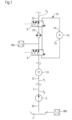
- FIG. 1 A section of an oil supply of a transmission is shown, which shows a particularly advantageous position of the temperature sensor 36a.
- the partial section shows all the essential elements that an oil supply according to the invention for an automatic transmission or an automatic manual transmission must have.
- valves for pressure control or for switching or regulating the elements can be used as examples Fig 2 be removed.
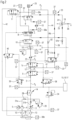
- Figure 2 An exemplary embodiment is shown, which shows all the details that will also be described below.
- an oil pumping device 3 is provided, by means of which oil is conveyed or pumped into the pressure line 2, 12, 22, 32 via an oil line 30.
- the oil pressure is regulated so that there is a supply pressure P 0 in the pressure line section 2, which is regulated by a valve, not shown.
- the supply pressure P 0 is required, for example, to switch the clutches and brakes of a transmission in order to control or regulate the switching processes in the transmission.
- the hydrodynamic converter 18 is arranged in the pressure line 22.
- the oil pressure is lower, P 2 ⁇ P 0 . Oil flows through the converter in every operating state.
- Valves 8 and 9 are designed as 4/2-way valves. By switching the valves 8 and 9, the heat exchanger 33 is either a section of the pressure line or the heat exchanger is integrated into the retarder oil circuit 23, so that the braking energy is dissipated via the heat exchanger during operation of the retarder.
- the temperature sensor 36a is installed between the valve 8 and the heat exchanger 33. In both switching positions of the valves 8, 9, the oil temperature of the oil can be measured either at the output of converter 18 or retarder 19. To optimize the operation of converter 18 and retarder 19, different temperature limits can be important. If the maximum temperature is exceeded, the converter 18 or the retarder 19 must be turned down. The position of the sensor in front of the heat exchanger 33 ensures optimal temperature monitoring because the actual process temperature is measured.
- the oil temperature in the oil sump is only relevant if the retarder is switched on and off frequently, since a relatively large amount of heated oil is drained from the working area into the oil sump 1.
- the oil in the converter is only slightly heated, so that in lock-up operation the temperature measured at sensor 36a approximately corresponds to the oil sump temperature.
- the measured temperature can be incorporated into a calculation model in order to calculate an oil sump temperature in converter or retarder operation.
- Figure 2 shows an exemplary embodiment of an oil supply to a transmission with all elements, in particular converter 18, retarder 19 and the lubrication points 20.
- the oil supply for the switching elements 17 branches off from the pressure line section 2, whereby the individual switching elements 17 are supplied with pressure oil via lines 16 and the switching and control valves 15.
- the switching elements 7, not shown here, can be clutches or brakes, which are actuated with the pressure oil.
- Pump 3 is coupled to the drive motor and designed as a controllable pump.
- the pump 4 is driven by an electric motor 5.
- the connection and control of the two oil pumps 3, 4 can be designed differently, with each circuit ensuring that a supply pressure P 0 can be set in front of the valve 6 and that there is always an oil volume flow through the pressure line 2, 12, 22 behind the valve 6. 32 and the valves 7, 8, 9, 10 can reach the lubrication points 20.
- Excess pressure oil which is not required for lubrication 20, can be directed back to the suction side of the first oil pump 3 via the bypass line 42.
- a hydrodynamic converter 18 is also provided in the pressure line 2, 12, 22, 32 as a starting element, through which pressure oil flows or is supplied.
- two heat exchangers 21, 33 are provided, one of which is positioned directly in the pressure line 2, 12, 22, 32 in front of the converter 18.
- Another heat exchanger 33 is arranged between the valves 8 and 9. Depending on the operating state of the drive train, this can be switched into the retarder operating circuit 23 to dissipate the retarder waste heat.
- a filling line 26, 41 branches off from the pressure line 2, 12, 22, 32 in the area of the first working pressure P 1 , via which the retarder 19 can be supplied with oil from the pressure line 2, 12, 22, 32.
- both heat exchangers 21, 33 are always integrated into the oil circuit, so that as little heat as possible is introduced into the oil sump 1 even in converter operation or in order to cool down the oil from the oil sump 1 as quickly as possible.
- only the heat exchanger 33 is integrated into the retarder oil circuit 23. The minimum oil flow is only conducted via the heat exchanger 21.
Landscapes
- Engineering & Computer Science (AREA)
- Mechanical Engineering (AREA)
- General Engineering & Computer Science (AREA)
- Transportation (AREA)
- Physics & Mathematics (AREA)
- Fluid Mechanics (AREA)
- Chemical & Material Sciences (AREA)
- Combustion & Propulsion (AREA)
- Automation & Control Theory (AREA)
- Control Of Transmission Device (AREA)
- General Details Of Gearings (AREA)
Description
- Die vorliegende Erfindung betrifft eine Ölversorgung eines Automatgetriebes oder automatisierten Schaltgetriebes in einem Antriebsstrang sowie ein Verfahren zur Versorgung eines solchen Automatgetriebes oder automatisierten Schaltgetriebes gemäß den unabhängigen Ansprüchen.
- Ölversorgungen von Automatgetrieben oder automatisierten Schaltgetrieben weisen herkömmlich eine Ölpumpe in einer Ölversorgungsleitung auf, mittels welcher Öl aus einem Ölsumpf in eine Druckleitung zur Druckölversorgung von Elementen des Getriebes gefördert wird. Die Ölpumpe wird durch den Verbrennungsmotor angetrieben, mit welchem Antriebsleistung in einen Kraftfahrzeugantriebsstrang, in dem das Getriebe mit der Ölversorgung vorgesehen ist, um Antriebsleistung des Verbrennungsmotors auf Antriebsräder des Kraftfahrzeugs zu übertragen, eingespeist wird. In der Regel ist die Ölpumpe im Getriebe positioniert. Eine solche Ölpumpe wird auch als mechanische Ölpumpe bezeichnet.
- Zu den unterschiedlichen Elementen, die in einem Automatgetriebe oder automatisierten Schaltgetrieben vorhanden sind, zählen Kupplungen, Bremsen, ein Wandler, eine hydrodynamische Bremse (Retarder) sowie die Schmierstellen eines Getriebes. Die unterschiedlichen Elemente benötigen während des Fahrzeugbetriebs zu unterschiedlichen Zeitpunkten ein sehr unterschiedliches Ölvolumen mit sehr unterschiedlichen Öldrücken.
-
DE 10 2009 035 082 A offenbart einen Getriebeölkreislauf mit einer Ölpumpe, einem Wärmetauscher, einem hydrodynamischen Retarder, einem Retarderwärmetauscher, steuerbare Schaltventile und einem hydrodynamischen Wandler. Eine weitere Ölversorgung wird in der Reparaturanleitung ZF-ECOLIFE, Ausgabe 2008-01 der ZF Friedrichshafen AG gezeigt. - Für den sicheren und störungsfreien Betrieb eines Automatgetriebes oder automatisierten Schaltgetriebes ist es unter anderem wichtig, dass die Öltemperatur in bestimmten Grenzen bleibt.
- Der vorliegenden Erfindung liegt die Aufgabe zugrunde, eine Ölversorgung für ein Automatgetriebe oder automatisierten Schaltgetriebe sowie ein Verfahren anzugeben, mit welcher eine erhöhte Betriebsicherheit erreicht wird.
- Die erfindungsgemäße Aufgabe wird durch eine Ölversorgung und ein Verfahren mit den Merkmalen der unabhängigen Ansprüche gelöst. In den abhängigen Ansprüchen sind vorteilhafte und besonders zweckmäßige Ausgestaltungen der Erfindung angegeben.
- Eine erfindungsgemäße Ölversorgung eines Automatgetriebes oder automatisierten Schaltgetriebes weist einen Ölsumpf und eine Druckleitung zur Druckölversorgung von Elementen des Getriebes auf. Bei den Elementen handelt es sich beispielsweise um Schaltelemente wie Kupplungen und/oder Bremsen, insbesondere in Lamellenbauart, die betätigt werden, um wahlweise eine von mehreren möglichen Übersetzungen zwischen einer Getriebeeingangswelle und einer Getriebeausgangswelle des Getriebes einzustellen, wodurch einzelne Gangstufen in dem Getriebe dargestellt werden können.
- Weiterhin werden mit dem Öl der Ölversorgung Elemente wie ein hydrodynamischer Wandler, eine hydrodynamische Bremse, Retarder und die Schmierung z.B der Lager versorgt bzw. betrieben. Insbesondere wird das Öl der Ölversorgung als Arbeitsmedium für den Wandler und den Retarder verwendet.
- Ferner ist eine Pumpvorrichtung vorgesehen, um Öl aus dem Ölsumpf auf einen Versorgungsdruck P0 in die Druckleitung zu fördern. Die Pumpvorrichtung ist in einer Ölleitung positioniert, welche in die Druckleitung übergeht oder durch welche die Druckleitung gebildet wird.
- Die Pumpvorrichtung kann aus einer mit dem Antriebsmotor gekoppelten Ölpumpe oder alternativ aus einer mit einem elektrischen Motor angetriebenen Ölpumpe oder einer Kombination aus Beiden bestehen.
- Zu den Elementen der Ölversorgung gehört weiterhin ein hydrodynamischer Wandler als Anfahrelement, der einen Teilabschnitt der Druckleitung bildet, und ein hydrodynamischer Retarder in einem Retarderölkreislauf.
- In der Druckleitung sind zumindest ein erstes Schaltventil, ein zweites Schaltventil und ein Wärmetauscher vorgesehen, wobei der Wärmetauscher mittels der Schaltventile wahlweise als Teilabschnitt in die Druckleitung oder den Retarderölkreislauf schaltbar ist. Die Schaltventile sind vorzugsweise Federrückstellend und können einzeln oder zusammen über ein Betätigungsventil angesteuert werden.
- Erfindungsgemäß ist ein Temperatursensor in Strömungsrichtung hinter der Pumpvorrichtung vorgesehen, um die Öltemperatur in der Druckleitung zu erfassen.
- Durch diese Positionierung des Temperatursensors können insbesondere kritische Temperaturen in der Druckleitung erfasst werden. Zur weiteren Verbesserung der Betriebssicherheit ist der Temperatursensor in Strömungsrichtung gesehen hinter dem hydrodynamischen Wandler vorgesehen.
- Die Position des Temperatursensors ist zwischen dem ersten Ventil und dem Wärmetauscher. Ein hier positionierter Temperatursensor kann insbesondere zur Regelung des Wandlers und des Retarders verwendet werden. Steigt die Öltemperatur an dieser Position der Druckleitung zu stark, ist es erforderlich in die Regelung von Wandler oder Retarder einzugreifen, um eine Überhitzung des Ölkreislaufes zu verhindern.
- Weiterhin können Ventile in der Druckleitung vorgesehen sein, mittels denen in Teilabschnitten der Druckleitung der Versorgungsdruck P0, in Strömungsrichtung gesehen, auf unterschiedlichen Arbeitsdrück P1, P2, P3 ,regelbar ist, wobei gilt P0 > P1 > P2 > P3.
- In einer weiteren Ausführung kann ein zweiter Temperatursensor zur Messung der Ölsumpftemperatur vorhanden sein, wodurch die Regelung des Getriebes weiter verbessert wird, da das gesamte Ölvolumen berücksichtigt wird.
- Ein erfindungsgemäßes Verfahren sieht vor, dass unabhängig vom Betriebszustand des Kraftfahrzeugantriebsstrangs die Öltemperatur in der Druckleitung gemessen wird, wobei weiterhin vorgesehen ist,
- im Lock-Up Betrieb: die Ermittlung der Ölsumpftemperatur;
- im Wandlerbetrieb: Reduzierung der Getriebeeingangsleitung bei Überschreitung einer ersten Temperaturgrenze Tmax W;
- im Retarderbetrieb, bzw. im Bremsbetrieb: Reduzierung der Retarderleistung bei Überschreitung einer zweiten Temperaturgrenze Tmax R;
- Zu den Betriebszustände zählen hauptsächlich der Anfahrbetrieb mit Wandler, der Fahrbetrieb mit überbrücktem Wandler, Lock-Up-Betrieb und der Bremsbetrieb, aber auch die Betriebszustände der anderen Aggregate des Antriebstrangs wie dem Motor usw. zählen dazu.
- Weiterhin kann vorgesehen sein, dass die erste Temperaturgrenze Tmax W und die zweite Temperaturgrenze Tmax R an den Betriebszustand des Antriebsstrangs angepasst wird.
- So kann in einem weiteren Schritt die Ölsumpftemperatur mittels eines Berechnungsmodels ermittelt werden, so dass ein zweiter Temperatursensor zur Messung der Ölsumpftemperatur entfallen kann.
- Um die Ölsumpftemperaturermittlung zu verbessern, kann weiterhin das Berechnungsmodel in dem Zeitfenster abgeglichen werden, in dem der Wandler im Loch-Up Betrieb arbeitet und der Wärmetauscher mittels der Ventile in die Druckleitung geschaltet ist. In diesem Betriebszustand wird das Öl durch die Elemente nur geringfügig erwärmt.
- Nachfolgend wird die Erfindung anhand von Skizzen näher erläutert.
- In diesen zeigen:
- Figur 1
- einen Ausschnitt einer Ölversorgung eines Getriebes mit Temperatursensor,
- Figur 2
- ein Beispiel für eine Ausführung einer Ölversorgung eines Getriebes;
- In
Figur 1 ist ein Ausschnitt einer Ölversorgung eines Getriebes dargestellt, aus der eine besonders vorteilhafte Position des Temperatursensors 36a hervorgeht. - Der Teilausschnitt zeigt alle wesentlichen Elemente die eine erfindungsgemäße Ölversorgung für ein Automatgetriebe oder ein automatisches Schaltgetriebe aufweisen muss.
- Nicht dargestellte Details, wie Ventile zur Druckregelung oder zum Schalten oder Regeln der Elemente können Beispielhaft aus
Fig 2 entnommen werden. InFigur 2 ist ein Ausführungsbeispiel dargestellt, aus dem alle Details hervorgehen, die nachfolgend auch noch beschrieben werden. - Zur Ölversorgung ist eine Ölpumpvorrichtung 3 vorgesehen, mittels der Öl über eine Ölleitung 30 in die Druckleitung 2, 12, 22, 32 gefördert bzw. gepumpt wird. Der Öldruck wird so geregelt, dass im Druckleitungsabschnitt 2 ein Versorgungsdruck P0 vorliegt, der von einem nicht dargestellten Ventil geregelt wird. Der Versorgungsdruck P0 wird beispielsweise zur Schaltung der Kupplungen und Bremsen eines Getriebes benötigt, um die Schaltvorgänge im Getriebe zu steuern bzw. zu regeln.
- Im weiteren Verlauf der Druckleitung 2, 12, 22, 32 ist der hydrodynamische Wandler 18 in der Druckleitung 22 angeordnet. In diesem Abschnitt der Druckleitung ist der Öldruck geringer, P2<P0. Der Wandler wird in jedem Betriebszustand von Öl durchströmt.
- Im nächsten dargestellten Abschnitt sind unter anderem der Wärmetauscher 33 und der Retarderölkreislauf 23 dargestellt. Die Ventile 8 und 9 sind als 4/2 Wegeventile ausgeführt. Durch das Schalten der Ventile 8 und 9 ist der Wärmetauscher 33 entweder ein Teilabschnitt der Druckleitung oder der Wärmetauscher ist in den Retarderölkreislauf 23 integriert, so dass im Betrieb des Retarders die Bremsenergie über den Wärmetauscher abgeführt wird.
- Der Temperatursensor 36a ist zwischen dem Ventil 8 und dem Wärmetauscher 33 installiert. So kann in beiden Schaltstellungen der Ventile 8, 9 die Öltemperatur des Öls entweder am Ausgang von Wandler 18 oder Retarder 19 gemessen werden. Zur Optimierung des Betriebs von Wandler 18 und Retarder 19 können unterschiedliche Temperaturgrenzen maßgeblich sein. Wird die Maximaltemperatur überschritten muss der Wandler 18 oder der Retarder 19 heruntergeregelt werden. Die Position des Sensors vor dem Wärmetauscher 33 gewährleistet eine optimale Temperaturüberwachung, da die tatsächliche Prozesstemperatur gemessen wird.
- Die Öltemperatur im Ölsumpf ist dagegen nur bei häufigem an- und abschalten des Retarders relevant, da dabei relativ viel erhitztes Öl aus dem Arbeitsraum in den Ölsumpf 1 abgeführt wird.
- Im Lock-Up Betrieb wird das Öl im Wandler nur unwesentlich erhitzt, so dass im Lock-Up Betrieb die gemessene Temperatur am Sensor 36a annähernd der Ölsumpftemperatur entspricht. Die gemessene Temperatur kann in ein Berechnungsmodell einfließen um auch im Wandler- oder Retarderbetrieb eine Ölsumpftemperatur zu berechnen.
-
Figur 2 zeigt ein Ausführungsbeispiel für eine Ölversorgung eines Getriebes mit allen Elementen, insbesondere Wandler 18, Retarder 19. und die Schmierstellen 20. - Von dem Druckleitungsabschnitt 2 zweigt die Ölversorgung für die Schaltelemente 17 ab, wobei die einzelnen Schaltelemente 17 über Leitungen 16 und die Schalt- und Steuerventile 15 mit Drucköl versorgt werden. Die hier nicht näher dargestellten Schaltelemente 7 können Kupplungen oder Bremsen sein, deren Betätigung mit dem Drucköl erfolgt.
- Zur Ölversorgung sind hier zwei Pumpen 3 und 4 vorgesehen. Dabei ist Pumpe 3 an den Antriebsmotor gekoppelt und als regelbare Pumpe ausgeführt. Die Pumpe 4 ist über einen elektrischen Motor 5 angetrieben. Die Verschaltung und Regelung der beiden Ölpumpen 3, 4 können unterschiedlich ausgeführt sein, wobei bei jeder Schaltung sichergestellt ist, dass vor dem Ventil 6 ein Versorgungsdruck P0 einstellbar ist und hinter dem Ventil 6 immer ein Ölvolumenstrom durch die Druckleitung 2, 12, 22, 32 und die Ventile 7, 8, 9, 10 bis zu den Schmierstellen 20 gelangen kann.
- Überschüssiges Drucköl, welches nicht für die Schmierung 20 benötigt wird, kann über die Bypassleitung 42 zurück auf die Ansaugseite der ersten Ölpumpe 3 geleitet werden.
- In den beiden dargestellten Ausführungen ist weiterhin in der Druckleitung 2, 12, 22, 32 ein hydrodynamischer Wandler 18 als Anfahrelement vorgesehen, der mit Drucköl durchströmt bzw. versorgt wird. Zur Kühlung des Ölstroms sind zwei Wärmetauscher 21, 33 vorgesehen, wobei einer direkt in der Druckleitung 2, 12, 22, 32 vor dem Wandler 18 positioniert ist. Ein weiterer Wärmetauscher 33 ist zwischen den Ventilen 8 und 9 angeordnet. Dieser kann entsprechend dem Betriebszustand des Antriebstrangs in den Retarderbetriebskreislauf 23, zur Abführung der Retarderabwärme, geschaltet werden.
- Zur Befüllung des Retarderölkreislaufs 23 zweigt von der Druckleitung 2, 12, 22, 32 im Bereich des ersten Arbeitsdruckes P1 eine Befüllleitung 26, 41 ab, über die der Retarder 19 mit Öl aus der Druckleitung 2, 12, 22, 32 versorgbar ist.
- In der Ausführung ist neben dem Wärmetauscher 33 ein weiterer Wärmetauscher 21 vor dem Wandler 18 installiert. In diesem Wärmetauscher 21 wird das Öl gekühlt bevor es in den Wandler 18 gelangt.
- Im Nicht-Bremsbetrieb des Retarders 19 sind immer beide Wärmetauscher 21, 33 in den Ölkreislauf eingebunden, sodass auch im Wandlerbetrieb möglichst wenig Wärme in den Ölsumpf 1 eingebracht wird bzw. um das Öl aus dem Ölsumpf 1 möglichst schnell herunter zu kühlen. Im Bremsbetrieb des Retarders 19 ist nur der Wärmetauscher 33 in den Retarderölkreislauf 23 eingebunden. Der Mindestölstrom wird nur über den Wärmetauscher 21 geleitet.
- Weitere in der
Figur 2 dargestellte Details bzw. Elemente sind Details, die für die Ölversorgung notwendig sind, aber nicht direkt für die erfindungsgemäße Ausführung relevant sind. Auf diese wurde hier nicht näher eingegangen, da sie dem Fachmann allgemein bekannt sind und die Funktion aus den Schaltbildern hervorgeht. Hierzu zählen insbesondere die Rückschlagventile 28, bzw. die Druckbegrenzungsventile 28.1, die Sensoren 36, 37, sowie die nicht erwähnten Ventile, Filter usw.
Claims (7)
- Ölversorgung eines Automatgetriebes oder automatisierten Schaltgetriebes, geeignet zum Einbau in einem Antriebsstrang,1.1 mit einem Ölsumpf (1);1.2 mit einer Druckleitung (2, 12, 22, 32) zur Druckölversorgung von Elementen (17, 18, 19, 20) des Getriebes;1.3 mit einer Pumpvorrichtung (3), um Öl aus dem Ölsumpf (1) auf einen Versorgungsdruck P0 in die Druckleitung (2, 12, 22, 32) zu fördern;1.4 mit einem hydrodynamischen Wandler (18) als Anfahrelement, der einen Teilabschnitt der Druckleitung bildet;1.5 mit einem hydrodynamischen Retarder (19), in einem Retarderölkreislauf (23)1.6 mit in der Druckleitung (2, 12, 22, 32) zumindest einem ersten Schaltventil (8), einem zweiten Schaltventil (9) und einem zwischen dem ersten Schaltventil (8) und zweiten Schaltventil (9) angeordneten Wärmetauscher (33), wobei der Wärmetauscher (33) mittels der Schaltventile (8, 9) wahlweise als Teilabschnitt in die Druckleitung (2, 12, 22, 32) oder den Retarderölkreislauf (23) schaltbar ist;dadurch gekennzeichnet,
1.7 dass ein Temperatursensor (36a) in Strömungsrichtung hinter der Pumpvorrichtung (3) vorgesehen ist, um die Öltemperatur in der Druckleitung (2, 12, 22, 32) zu erfassen, wobei
der Temperatursensor (36a) zwischen dem ersten Ventil (8) und dem Wärmetauscher (33) und in Abhängigkeit einer Schaltstellung der Schaltventile (8, 9) in Strömungsrichtung hinter dem hydrodynamischen Wandler (18) oder dem hydrodynamischen Retarder (19) zur Messung der Öltemperatur am Ausgang des hydrodynamischen Wandlers (18) oder des hydrodynamischen Retarders (19) angeordnet ist. - Ölversorgung gemäß Anspruch 1,
dadurch gekennzeichnet,
dass Ventile (6, 7, 10, 11, 27) in der Druckleitung (2, 12, 22, 32) vorgesehen sind, mittels denen in Teilabschnitten der Druckleitung (2, 12, 22, 32) der Versorgungsdruck P0, in Strömungsrichtung gesehen, auf unterschiedlichen Arbeitsdrücke P1, P2, P3 regelbar ist, wobei gilt P0 > P1 > P2 > P3 - Ölversorgung gemäß Anspruch 1 oder 2,
dadurch gekennzeichnet,
dass ein zweiter Temperatursensor (36b) zur Messung der Ölsumpftemperatur vorhanden ist. - Verfahren zum Versorgen eines Automatgetriebes oder automatisierten Schaltgetriebes mit Drucköl mit einer Ölversorgung gemäß einem der Ansprüche 1 bis 3, mit folgenden Schritten:- Messen der Öltemperatur mit dem Temperatursensor (36a) in der Druckleitung (2, 12, 22, 32);- im Lock-Up Betrieb: Ermittlung der Ölsumpftemperatur;- im Wandlerbetrieb: Reduzierung der Getriebeeingangsleistung bei Überschreitung einer ersten Temperaturgrenze Tmax W;- im Retarderbetrieb bzw. im Bremsbetrieb: Reduzierung der Retarderleistung bei Überschreitung einer zweiten Temperaturgrenze Tmax R;
- Verfahren gemäß Anspruch 4,
dadurch gekennzeichnet,
dass die erste Temperaturgrenze Tmax W und die zweite Temperaturgrenze Tmax R an den Betriebszustand des Antriebsstrangs anpassbar sind. - Verfahren gemäß Anspruch 4 oder 5,
dadurch gekennzeichnet,
dass die Ölsumpftemperatur mittels eines Berechnungsmodels ermittelt wird. - Verfahren gemäß Anspruch 6,
dadurch gekennzeichnet,
dass das Berechnungsmodel abgeglichen und ggf. korrigiert wird, wenn der Wandler im Lock-Up Betrieb arbeitet und der Wärmetauscher (33) mittels der Ventile (8, 9) in die Druckleitung geschaltet ist.
Applications Claiming Priority (2)
| Application Number | Priority Date | Filing Date | Title |
|---|---|---|---|
| DE102015218358.0A DE102015218358A1 (de) | 2015-09-24 | 2015-09-24 | Ölversorgung eines Automatgetriebes oder automatisierten Schaltgetriebes, in einem Antriebsstrang |
| PCT/EP2016/072115 WO2017050674A1 (de) | 2015-09-24 | 2016-09-19 | Ölversorgung eines automatgetriebes oder automatisierten schaltgetriebes, in einem antriebsstrang |
Publications (3)
| Publication Number | Publication Date |
|---|---|
| EP3353452A1 EP3353452A1 (de) | 2018-08-01 |
| EP3353452B1 EP3353452B1 (de) | 2020-06-03 |
| EP3353452B2 true EP3353452B2 (de) | 2024-01-03 |
Family
ID=56940067
Family Applications (1)
| Application Number | Title | Priority Date | Filing Date |
|---|---|---|---|
| EP16766570.2A Active EP3353452B2 (de) | 2015-09-24 | 2016-09-19 | Ölversorgung eines automatgetriebes oder automatisierten schaltgetriebes, in einem antriebsstrang |
Country Status (4)
| Country | Link |
|---|---|
| US (1) | US10816090B2 (de) |
| EP (1) | EP3353452B2 (de) |
| DE (1) | DE102015218358A1 (de) |
| WO (1) | WO2017050674A1 (de) |
Families Citing this family (10)
| Publication number | Priority date | Publication date | Assignee | Title |
|---|---|---|---|---|
| JP6187415B2 (ja) * | 2014-08-22 | 2017-08-30 | トヨタ自動車株式会社 | 潤滑制御装置 |
| WO2018189203A1 (en) * | 2017-04-11 | 2018-10-18 | Dana Belgium N.V. | Hydrodynamic retarder system |
| EP3728904B1 (de) * | 2017-12-21 | 2022-01-05 | Volvo Truck Corporation | Hilfsgetriebebremsanordnung |
| DE102018002042A1 (de) * | 2018-03-14 | 2019-09-19 | Daimler Ag | Hydrauliksystem für ein Kraftfahrzeuggetriebe |
| JP2019168250A (ja) * | 2018-03-22 | 2019-10-03 | 本田技研工業株式会社 | モータユニット及び車両 |
| CN108980324B (zh) * | 2018-08-31 | 2023-09-26 | 吉测(苏州)测试系统有限公司 | 变速器温度控制系统 |
| DE102018122333A1 (de) | 2018-09-13 | 2020-03-19 | Voith Patent Gmbh | Ölkühlkreislauf eines Automatikgetriebes |
| DE102018219151B4 (de) * | 2018-11-09 | 2024-02-22 | Zf Friedrichshafen Ag | Betriebsmittelkreislauf eines Getriebes |
| DE102022106542A1 (de) | 2022-03-21 | 2023-09-21 | Voith Patent Gmbh | Automatgetriebe mit Wandler und dessen Regelung |
| DE102022109525B3 (de) | 2022-04-20 | 2023-06-29 | Voith Patent Gmbh | Automatgetriebe mit Wandler und die Regelung des Wandlers |
Family Cites Families (14)
| Publication number | Priority date | Publication date | Assignee | Title |
|---|---|---|---|---|
| DE2518103C3 (de) | 1975-04-23 | 1981-06-25 | Zahnräderfabrik Renk AG, 8900 Augsburg | Hydraulische Anlage für ein Fahrzeug |
| DE3430456A1 (de) | 1984-08-18 | 1985-10-31 | Daimler-Benz Ag, 7000 Stuttgart | Kuehlvorrichtung fuer hydraulisches arbeitsmittel einer hydrodynamischen bremse und schmieroel eines wechselgetriebes |
| DE19911352A1 (de) | 1999-03-15 | 2000-10-12 | Voith Turbo Kg | Getriebebaueinheit |
| DE10231610A1 (de) | 2002-07-12 | 2004-02-12 | Zf Friedrichshafen Ag | Verfahren zur Begrenzung der Bremswirkung eines Retarders in Abhängigkeit von der Temperatur |
| DE10248176A1 (de) | 2002-10-16 | 2004-05-19 | Zf Friedrichshafen Ag | Kühlkreislauf für den Antriebstrang eines Kraftfahrzeugs |
| DE102006030792A1 (de) | 2006-06-30 | 2008-01-03 | Zf Friedrichshafen Ag | Hydrodynamischer Retarder |
| DE102006030791A1 (de) | 2006-06-30 | 2008-01-03 | Zf Friedrichshafen Ag | Hydrodynamischer Retarder |
| DE102007008446A1 (de) | 2007-02-19 | 2008-08-21 | Voith Patent Gmbh | Verfahren und Vorrichtung zum Optimieren der Bremsarbeit eines Retarders |
| DE102009035082A1 (de) | 2009-07-28 | 2011-02-10 | Voith Patent Gmbh | Getriebeölkreislauf |
| FR2981140B1 (fr) | 2011-10-06 | 2013-11-01 | Renault Sa | Procede et systeme de commande d'un groupe motopropulseur en fonction de la temperature d'un convertisseur de couple hydraulique. |
| US20140379241A1 (en) | 2013-06-20 | 2014-12-25 | GM Global Technology Operations LLC | Hydraulic accumulator temperature estimation for controlling automatic engine stop/start |
| DE102013215907B4 (de) | 2013-08-12 | 2021-08-26 | Zf Friedrichshafen Ag | Verfahren zur Ermittlung einer Öltemperatur bei einem Getriebe |
| DE102013219792A1 (de) | 2013-09-30 | 2015-04-02 | Voith Patent Gmbh | Hydrauliksystem für eine hydrodynamische Maschine |
| WO2015105482A1 (en) | 2014-01-08 | 2015-07-16 | Allison Transmission, Inc. | System for adjusting fluid volume in a transmission and method thereof |
-
2015
- 2015-09-24 DE DE102015218358.0A patent/DE102015218358A1/de not_active Withdrawn
-
2016
- 2016-09-19 EP EP16766570.2A patent/EP3353452B2/de active Active
- 2016-09-19 US US15/761,640 patent/US10816090B2/en active Active
- 2016-09-19 WO PCT/EP2016/072115 patent/WO2017050674A1/de unknown
Non-Patent Citations (1)
| Title |
|---|
| ANONYMOUS: "Reparaturanleitung ZF-EcoLife", ZF, 1 January 2008 (2008-01-01), [retrieved on 20221114] † |
Also Published As
| Publication number | Publication date |
|---|---|
| EP3353452B1 (de) | 2020-06-03 |
| EP3353452A1 (de) | 2018-08-01 |
| US10816090B2 (en) | 2020-10-27 |
| DE102015218358A1 (de) | 2017-03-30 |
| US20180347691A1 (en) | 2018-12-06 |
| WO2017050674A1 (de) | 2017-03-30 |
Similar Documents
| Publication | Publication Date | Title |
|---|---|---|
| EP3353452B2 (de) | Ölversorgung eines automatgetriebes oder automatisierten schaltgetriebes, in einem antriebsstrang | |
| DE19823772B4 (de) | Verfahren zum Betreiben einer automatisierten Kupplung | |
| DE102005059356A1 (de) | Hydrauliksystem an Kraftfahrzeugen | |
| DE102006024011A1 (de) | Verfahren und Vorrichtung zur Einstellung und Ansteuerung eines hydrodynamischen Retarders eines Kraftfahrzeuges | |
| DE112007001226B4 (de) | Dreistellungs-Steuersolenoid zur hydraulischen Betätigung | |
| WO2017050724A1 (de) | Antriebsstrang mit automatgetriebe oder automatisiertem schaltgetriebe, einer ölversorgung und einem hydrodynamischen retarder | |
| WO2020053058A1 (de) | Ölkühlkreislauf eines automatikgetriebes | |
| DE10141794A1 (de) | Hydrodynamischer Retarder | |
| DE102006006179B4 (de) | Vorrichtung zum Betreiben eines hydrodynamischen Drehmomentwandlers und einer damit korrespondierenden Wandlerüberbrückungskupplung einer Getriebeeinrichtung | |
| DE102006036186A1 (de) | Fahrzeugkühlkreislauf zur Kühlung eines Antriebsmotors und einer hydrodynamischen Bremse | |
| WO2004085884A2 (de) | Hydrodynamischer drehmomentwandler | |
| EP2464886B1 (de) | Verfahren zur steuerung der kühlmittelzufuhr und der schmiermittelzufuhr einer kupplung eines kraftfahrzeuges mit einem automatischen schaltgetriebe | |
| WO2008012169A1 (de) | Automatisiertes schaltsystem | |
| DE2518103C3 (de) | Hydraulische Anlage für ein Fahrzeug | |
| EP1608525B1 (de) | Verfahren zum betrieb eines antriebsstrangs zum antrieb eines mobil-fahrzeugs | |
| DE60011364T2 (de) | Hydrostatische Fahrzeuglenkung mit Zusatzpumpe | |
| DE10014731C1 (de) | Vorrichtung mit zumindest einer Hydraulikeinheit zur Druckversorgung eines Getriebes | |
| DE102010049989A1 (de) | Vorrichtung und Verfahren zum Einstellen des Ölstandes in einem Getriebe | |
| EP3052350B1 (de) | Hydrauliksystem für eine hydrodynamische maschine | |
| WO2017050682A1 (de) | Ölversorgung eines automatgetriebes oder automatisierten schaltgetriebes,kraftfahrzeugantriebsstrang und verfahren zur versorgung eines solchen getriebes | |
| DE102016215217B4 (de) | Verfahren zum Betätigen eines elektrohydraulischen Getriebesteuersystems eines Doppelkupplungsgetriebes | |
| DE10314330A1 (de) | Hydrodynamischer Drehmomentwandler | |
| DE102006006180A1 (de) | Vorrichtung zum Betreiben eines hydrodynamischen Drehmomentwandlers und einer damit korrespondierenden Wandlerüberbrückungskupplung einer Getriebeeinrichtung | |
| DE19842478A1 (de) | Fluidbetriebene Kupplungsbremse für Getriebe | |
| DE112006002744T5 (de) | Motorsteuereinrichtung |
Legal Events
| Date | Code | Title | Description |
|---|---|---|---|
| STAA | Information on the status of an ep patent application or granted ep patent |
Free format text: STATUS: THE INTERNATIONAL PUBLICATION HAS BEEN MADE |
|
| PUAI | Public reference made under article 153(3) epc to a published international application that has entered the european phase |
Free format text: ORIGINAL CODE: 0009012 |
|
| STAA | Information on the status of an ep patent application or granted ep patent |
Free format text: STATUS: REQUEST FOR EXAMINATION WAS MADE |
|
| 17P | Request for examination filed |
Effective date: 20180424 |
|
| AK | Designated contracting states |
Kind code of ref document: A1 Designated state(s): AL AT BE BG CH CY CZ DE DK EE ES FI FR GB GR HR HU IE IS IT LI LT LU LV MC MK MT NL NO PL PT RO RS SE SI SK SM TR |
|
| AX | Request for extension of the european patent |
Extension state: BA ME |
|
| DAV | Request for validation of the european patent (deleted) | ||
| DAX | Request for extension of the european patent (deleted) | ||
| GRAP | Despatch of communication of intention to grant a patent |
Free format text: ORIGINAL CODE: EPIDOSNIGR1 |
|
| STAA | Information on the status of an ep patent application or granted ep patent |
Free format text: STATUS: GRANT OF PATENT IS INTENDED |
|
| RIC1 | Information provided on ipc code assigned before grant |
Ipc: F16H 61/00 20060101AFI20190927BHEP Ipc: B60T 10/02 20060101ALI20190927BHEP Ipc: B60T 1/087 20060101ALI20190927BHEP Ipc: F16D 57/04 20060101ALI20190927BHEP |
|
| INTG | Intention to grant announced |
Effective date: 20191016 |
|
| RAP1 | Party data changed (applicant data changed or rights of an application transferred) |
Owner name: VOITH PATENT GMBH |
|
| GRAJ | Information related to disapproval of communication of intention to grant by the applicant or resumption of examination proceedings by the epo deleted |
Free format text: ORIGINAL CODE: EPIDOSDIGR1 |
|
| STAA | Information on the status of an ep patent application or granted ep patent |
Free format text: STATUS: REQUEST FOR EXAMINATION WAS MADE |
|
| GRAP | Despatch of communication of intention to grant a patent |
Free format text: ORIGINAL CODE: EPIDOSNIGR1 |
|
| STAA | Information on the status of an ep patent application or granted ep patent |
Free format text: STATUS: GRANT OF PATENT IS INTENDED |
|
| INTC | Intention to grant announced (deleted) | ||
| INTG | Intention to grant announced |
Effective date: 20200218 |
|
| GRAS | Grant fee paid |
Free format text: ORIGINAL CODE: EPIDOSNIGR3 |
|
| GRAA | (expected) grant |
Free format text: ORIGINAL CODE: 0009210 |
|
| STAA | Information on the status of an ep patent application or granted ep patent |
Free format text: STATUS: THE PATENT HAS BEEN GRANTED |
|
| AK | Designated contracting states |
Kind code of ref document: B1 Designated state(s): AL AT BE BG CH CY CZ DE DK EE ES FI FR GB GR HR HU IE IS IT LI LT LU LV MC MK MT NL NO PL PT RO RS SE SI SK SM TR |
|
| REG | Reference to a national code |
Ref country code: GB Ref legal event code: FG4D Free format text: NOT ENGLISH |
|
| REG | Reference to a national code |
Ref country code: CH Ref legal event code: EP Ref country code: AT Ref legal event code: REF Ref document number: 1277348 Country of ref document: AT Kind code of ref document: T Effective date: 20200615 |
|
| REG | Reference to a national code |
Ref country code: DE Ref legal event code: R096 Ref document number: 502016010135 Country of ref document: DE |
|
| REG | Reference to a national code |
Ref country code: SE Ref legal event code: TRGR |
|
| REG | Reference to a national code |
Ref country code: LT Ref legal event code: MG4D |
|
| PG25 | Lapsed in a contracting state [announced via postgrant information from national office to epo] |
Ref country code: LT Free format text: LAPSE BECAUSE OF FAILURE TO SUBMIT A TRANSLATION OF THE DESCRIPTION OR TO PAY THE FEE WITHIN THE PRESCRIBED TIME-LIMIT Effective date: 20200603 Ref country code: GR Free format text: LAPSE BECAUSE OF FAILURE TO SUBMIT A TRANSLATION OF THE DESCRIPTION OR TO PAY THE FEE WITHIN THE PRESCRIBED TIME-LIMIT Effective date: 20200904 Ref country code: FI Free format text: LAPSE BECAUSE OF FAILURE TO SUBMIT A TRANSLATION OF THE DESCRIPTION OR TO PAY THE FEE WITHIN THE PRESCRIBED TIME-LIMIT Effective date: 20200603 Ref country code: NO Free format text: LAPSE BECAUSE OF FAILURE TO SUBMIT A TRANSLATION OF THE DESCRIPTION OR TO PAY THE FEE WITHIN THE PRESCRIBED TIME-LIMIT Effective date: 20200903 |
|
| REG | Reference to a national code |
Ref country code: NL Ref legal event code: MP Effective date: 20200603 |
|
| PG25 | Lapsed in a contracting state [announced via postgrant information from national office to epo] |
Ref country code: LV Free format text: LAPSE BECAUSE OF FAILURE TO SUBMIT A TRANSLATION OF THE DESCRIPTION OR TO PAY THE FEE WITHIN THE PRESCRIBED TIME-LIMIT Effective date: 20200603 Ref country code: HR Free format text: LAPSE BECAUSE OF FAILURE TO SUBMIT A TRANSLATION OF THE DESCRIPTION OR TO PAY THE FEE WITHIN THE PRESCRIBED TIME-LIMIT Effective date: 20200603 Ref country code: BG Free format text: LAPSE BECAUSE OF FAILURE TO SUBMIT A TRANSLATION OF THE DESCRIPTION OR TO PAY THE FEE WITHIN THE PRESCRIBED TIME-LIMIT Effective date: 20200903 Ref country code: RS Free format text: LAPSE BECAUSE OF FAILURE TO SUBMIT A TRANSLATION OF THE DESCRIPTION OR TO PAY THE FEE WITHIN THE PRESCRIBED TIME-LIMIT Effective date: 20200603 |
|
| PG25 | Lapsed in a contracting state [announced via postgrant information from national office to epo] |
Ref country code: AL Free format text: LAPSE BECAUSE OF FAILURE TO SUBMIT A TRANSLATION OF THE DESCRIPTION OR TO PAY THE FEE WITHIN THE PRESCRIBED TIME-LIMIT Effective date: 20200603 Ref country code: NL Free format text: LAPSE BECAUSE OF FAILURE TO SUBMIT A TRANSLATION OF THE DESCRIPTION OR TO PAY THE FEE WITHIN THE PRESCRIBED TIME-LIMIT Effective date: 20200603 |
|
| PG25 | Lapsed in a contracting state [announced via postgrant information from national office to epo] |
Ref country code: EE Free format text: LAPSE BECAUSE OF FAILURE TO SUBMIT A TRANSLATION OF THE DESCRIPTION OR TO PAY THE FEE WITHIN THE PRESCRIBED TIME-LIMIT Effective date: 20200603 Ref country code: ES Free format text: LAPSE BECAUSE OF FAILURE TO SUBMIT A TRANSLATION OF THE DESCRIPTION OR TO PAY THE FEE WITHIN THE PRESCRIBED TIME-LIMIT Effective date: 20200603 Ref country code: CZ Free format text: LAPSE BECAUSE OF FAILURE TO SUBMIT A TRANSLATION OF THE DESCRIPTION OR TO PAY THE FEE WITHIN THE PRESCRIBED TIME-LIMIT Effective date: 20200603 Ref country code: RO Free format text: LAPSE BECAUSE OF FAILURE TO SUBMIT A TRANSLATION OF THE DESCRIPTION OR TO PAY THE FEE WITHIN THE PRESCRIBED TIME-LIMIT Effective date: 20200603 Ref country code: PT Free format text: LAPSE BECAUSE OF FAILURE TO SUBMIT A TRANSLATION OF THE DESCRIPTION OR TO PAY THE FEE WITHIN THE PRESCRIBED TIME-LIMIT Effective date: 20201006 Ref country code: SM Free format text: LAPSE BECAUSE OF FAILURE TO SUBMIT A TRANSLATION OF THE DESCRIPTION OR TO PAY THE FEE WITHIN THE PRESCRIBED TIME-LIMIT Effective date: 20200603 Ref country code: IT Free format text: LAPSE BECAUSE OF FAILURE TO SUBMIT A TRANSLATION OF THE DESCRIPTION OR TO PAY THE FEE WITHIN THE PRESCRIBED TIME-LIMIT Effective date: 20200603 |
|
| PG25 | Lapsed in a contracting state [announced via postgrant information from national office to epo] |
Ref country code: SK Free format text: LAPSE BECAUSE OF FAILURE TO SUBMIT A TRANSLATION OF THE DESCRIPTION OR TO PAY THE FEE WITHIN THE PRESCRIBED TIME-LIMIT Effective date: 20200603 Ref country code: PL Free format text: LAPSE BECAUSE OF FAILURE TO SUBMIT A TRANSLATION OF THE DESCRIPTION OR TO PAY THE FEE WITHIN THE PRESCRIBED TIME-LIMIT Effective date: 20200603 Ref country code: IS Free format text: LAPSE BECAUSE OF FAILURE TO SUBMIT A TRANSLATION OF THE DESCRIPTION OR TO PAY THE FEE WITHIN THE PRESCRIBED TIME-LIMIT Effective date: 20201003 |
|
| REG | Reference to a national code |
Ref country code: DE Ref legal event code: R026 Ref document number: 502016010135 Country of ref document: DE |
|
| PLBI | Opposition filed |
Free format text: ORIGINAL CODE: 0009260 |
|
| PLAX | Notice of opposition and request to file observation + time limit sent |
Free format text: ORIGINAL CODE: EPIDOSNOBS2 |
|
| 26 | Opposition filed |
Opponent name: ZF FRIEDRICHSHAFEN AG Effective date: 20210303 |
|
| PG25 | Lapsed in a contracting state [announced via postgrant information from national office to epo] |
Ref country code: DK Free format text: LAPSE BECAUSE OF FAILURE TO SUBMIT A TRANSLATION OF THE DESCRIPTION OR TO PAY THE FEE WITHIN THE PRESCRIBED TIME-LIMIT Effective date: 20200603 |
|
| REG | Reference to a national code |
Ref country code: CH Ref legal event code: PL |
|
| GBPC | Gb: european patent ceased through non-payment of renewal fee |
Effective date: 20200919 |
|
| PG25 | Lapsed in a contracting state [announced via postgrant information from national office to epo] |
Ref country code: SI Free format text: LAPSE BECAUSE OF FAILURE TO SUBMIT A TRANSLATION OF THE DESCRIPTION OR TO PAY THE FEE WITHIN THE PRESCRIBED TIME-LIMIT Effective date: 20200603 |
|
| REG | Reference to a national code |
Ref country code: BE Ref legal event code: MM Effective date: 20200930 |
|
| PG25 | Lapsed in a contracting state [announced via postgrant information from national office to epo] |
Ref country code: LU Free format text: LAPSE BECAUSE OF NON-PAYMENT OF DUE FEES Effective date: 20200919 |
|
| PLAF | Information modified related to communication of a notice of opposition and request to file observations + time limit |
Free format text: ORIGINAL CODE: EPIDOSCOBS2 |
|
| PG25 | Lapsed in a contracting state [announced via postgrant information from national office to epo] |
Ref country code: FR Free format text: LAPSE BECAUSE OF NON-PAYMENT OF DUE FEES Effective date: 20200930 |
|
| PG25 | Lapsed in a contracting state [announced via postgrant information from national office to epo] |
Ref country code: IE Free format text: LAPSE BECAUSE OF NON-PAYMENT OF DUE FEES Effective date: 20200919 Ref country code: LI Free format text: LAPSE BECAUSE OF NON-PAYMENT OF DUE FEES Effective date: 20200930 Ref country code: GB Free format text: LAPSE BECAUSE OF NON-PAYMENT OF DUE FEES Effective date: 20200919 Ref country code: CH Free format text: LAPSE BECAUSE OF NON-PAYMENT OF DUE FEES Effective date: 20200930 Ref country code: BE Free format text: LAPSE BECAUSE OF NON-PAYMENT OF DUE FEES Effective date: 20200930 |
|
| PLBB | Reply of patent proprietor to notice(s) of opposition received |
Free format text: ORIGINAL CODE: EPIDOSNOBS3 |
|
| PG25 | Lapsed in a contracting state [announced via postgrant information from national office to epo] |
Ref country code: TR Free format text: LAPSE BECAUSE OF FAILURE TO SUBMIT A TRANSLATION OF THE DESCRIPTION OR TO PAY THE FEE WITHIN THE PRESCRIBED TIME-LIMIT Effective date: 20200603 Ref country code: MT Free format text: LAPSE BECAUSE OF FAILURE TO SUBMIT A TRANSLATION OF THE DESCRIPTION OR TO PAY THE FEE WITHIN THE PRESCRIBED TIME-LIMIT Effective date: 20200603 Ref country code: CY Free format text: LAPSE BECAUSE OF FAILURE TO SUBMIT A TRANSLATION OF THE DESCRIPTION OR TO PAY THE FEE WITHIN THE PRESCRIBED TIME-LIMIT Effective date: 20200603 |
|
| PG25 | Lapsed in a contracting state [announced via postgrant information from national office to epo] |
Ref country code: MK Free format text: LAPSE BECAUSE OF FAILURE TO SUBMIT A TRANSLATION OF THE DESCRIPTION OR TO PAY THE FEE WITHIN THE PRESCRIBED TIME-LIMIT Effective date: 20200603 Ref country code: MC Free format text: LAPSE BECAUSE OF FAILURE TO SUBMIT A TRANSLATION OF THE DESCRIPTION OR TO PAY THE FEE WITHIN THE PRESCRIBED TIME-LIMIT Effective date: 20200603 |
|
| REG | Reference to a national code |
Ref country code: AT Ref legal event code: MM01 Ref document number: 1277348 Country of ref document: AT Kind code of ref document: T Effective date: 20210919 |
|
| PG25 | Lapsed in a contracting state [announced via postgrant information from national office to epo] |
Ref country code: AT Free format text: LAPSE BECAUSE OF NON-PAYMENT OF DUE FEES Effective date: 20210919 |
|
| PGFP | Annual fee paid to national office [announced via postgrant information from national office to epo] |
Ref country code: SE Payment date: 20230920 Year of fee payment: 8 Ref country code: DE Payment date: 20230920 Year of fee payment: 8 |
|
| PUAH | Patent maintained in amended form |
Free format text: ORIGINAL CODE: 0009272 |
|
| STAA | Information on the status of an ep patent application or granted ep patent |
Free format text: STATUS: PATENT MAINTAINED AS AMENDED |
|
| 27A | Patent maintained in amended form |
Effective date: 20240103 |
|
| AK | Designated contracting states |
Kind code of ref document: B2 Designated state(s): AL AT BE BG CH CY CZ DE DK EE ES FI FR GB GR HR HU IE IS IT LI LT LU LV MC MK MT NL NO PL PT RO RS SE SI SK SM TR |
|
| REG | Reference to a national code |
Ref country code: DE Ref legal event code: R102 Ref document number: 502016010135 Country of ref document: DE |
|
| REG | Reference to a national code |
Ref country code: SE Ref legal event code: RPEO |