EP3352541A1 - Boîtier - Google Patents
Boîtier Download PDFInfo
- Publication number
- EP3352541A1 EP3352541A1 EP16846312.3A EP16846312A EP3352541A1 EP 3352541 A1 EP3352541 A1 EP 3352541A1 EP 16846312 A EP16846312 A EP 16846312A EP 3352541 A1 EP3352541 A1 EP 3352541A1
- Authority
- EP
- European Patent Office
- Prior art keywords
- reinforcing structure
- bottom cover
- top cover
- joined
- housing
- Prior art date
- Legal status (The legal status is an assumption and is not a legal conclusion. Google has not performed a legal analysis and makes no representation as to the accuracy of the status listed.)
- Granted
Links
- 230000003014 reinforcing effect Effects 0.000 claims abstract description 291
- 238000005304 joining Methods 0.000 claims abstract description 133
- 230000000630 rising effect Effects 0.000 claims abstract description 42
- 239000000463 material Substances 0.000 claims description 207
- 229920005992 thermoplastic resin Polymers 0.000 claims description 34
- 238000003466 welding Methods 0.000 claims description 29
- 239000003733 fiber-reinforced composite Substances 0.000 claims description 13
- 230000020169 heat generation Effects 0.000 claims description 7
- 238000000034 method Methods 0.000 description 74
- 238000000465 moulding Methods 0.000 description 51
- 238000011156 evaluation Methods 0.000 description 45
- 229920005989 resin Polymers 0.000 description 41
- 239000011347 resin Substances 0.000 description 41
- 239000000853 adhesive Substances 0.000 description 25
- 230000001070 adhesive effect Effects 0.000 description 24
- 239000000835 fiber Substances 0.000 description 16
- 230000000052 comparative effect Effects 0.000 description 15
- 238000012360 testing method Methods 0.000 description 13
- -1 polyethylene Polymers 0.000 description 11
- 238000002360 preparation method Methods 0.000 description 11
- 230000001747 exhibiting effect Effects 0.000 description 9
- 238000010438 heat treatment Methods 0.000 description 9
- 230000010354 integration Effects 0.000 description 9
- 239000011159 matrix material Substances 0.000 description 9
- 239000007769 metal material Substances 0.000 description 9
- 229920001187 thermosetting polymer Polymers 0.000 description 7
- 239000004952 Polyamide Substances 0.000 description 6
- 229920002647 polyamide Polymers 0.000 description 6
- 239000013585 weight reducing agent Substances 0.000 description 6
- 238000004026 adhesive bonding Methods 0.000 description 5
- 229910045601 alloy Inorganic materials 0.000 description 5
- 239000000956 alloy Substances 0.000 description 5
- 230000000694 effects Effects 0.000 description 5
- 239000004745 nonwoven fabric Substances 0.000 description 5
- 229910000838 Al alloy Inorganic materials 0.000 description 4
- 229910000861 Mg alloy Inorganic materials 0.000 description 4
- KDLHZDBZIXYQEI-UHFFFAOYSA-N Palladium Chemical compound [Pd] KDLHZDBZIXYQEI-UHFFFAOYSA-N 0.000 description 4
- 229910001069 Ti alloy Inorganic materials 0.000 description 4
- 239000004973 liquid crystal related substance Substances 0.000 description 4
- 230000009467 reduction Effects 0.000 description 4
- 239000012783 reinforcing fiber Substances 0.000 description 4
- 238000009966 trimming Methods 0.000 description 4
- 239000004698 Polyethylene Substances 0.000 description 3
- 239000004734 Polyphenylene sulfide Substances 0.000 description 3
- 239000004743 Polypropylene Substances 0.000 description 3
- 238000001816 cooling Methods 0.000 description 3
- 239000012943 hotmelt Substances 0.000 description 3
- 238000001746 injection moulding Methods 0.000 description 3
- 238000002844 melting Methods 0.000 description 3
- 230000008018 melting Effects 0.000 description 3
- 229920002492 poly(sulfone) Polymers 0.000 description 3
- 229920000573 polyethylene Polymers 0.000 description 3
- 229920001955 polyphenylene ether Polymers 0.000 description 3
- 229920000069 polyphenylene sulfide Polymers 0.000 description 3
- 229920001155 polypropylene Polymers 0.000 description 3
- 238000010998 test method Methods 0.000 description 3
- 229920002292 Nylon 6 Polymers 0.000 description 2
- 229930040373 Paraformaldehyde Natural products 0.000 description 2
- 239000004697 Polyetherimide Substances 0.000 description 2
- 239000004642 Polyimide Substances 0.000 description 2
- PPBRXRYQALVLMV-UHFFFAOYSA-N Styrene Chemical compound C=CC1=CC=CC=C1 PPBRXRYQALVLMV-UHFFFAOYSA-N 0.000 description 2
- 238000005452 bending Methods 0.000 description 2
- 230000007423 decrease Effects 0.000 description 2
- 229920001971 elastomer Polymers 0.000 description 2
- 239000003822 epoxy resin Substances 0.000 description 2
- LNEPOXFFQSENCJ-UHFFFAOYSA-N haloperidol Chemical compound C1CC(O)(C=2C=CC(Cl)=CC=2)CCN1CCCC(=O)C1=CC=C(F)C=C1 LNEPOXFFQSENCJ-UHFFFAOYSA-N 0.000 description 2
- 230000017525 heat dissipation Effects 0.000 description 2
- 238000002347 injection Methods 0.000 description 2
- 239000007924 injection Substances 0.000 description 2
- 238000010030 laminating Methods 0.000 description 2
- 229910052763 palladium Inorganic materials 0.000 description 2
- 239000008188 pellet Substances 0.000 description 2
- 229920001652 poly(etherketoneketone) Polymers 0.000 description 2
- 229920003229 poly(methyl methacrylate) Polymers 0.000 description 2
- 229920001230 polyarylate Polymers 0.000 description 2
- 229920001707 polybutylene terephthalate Polymers 0.000 description 2
- 239000004417 polycarbonate Substances 0.000 description 2
- 229920000515 polycarbonate Polymers 0.000 description 2
- 229920005668 polycarbonate resin Polymers 0.000 description 2
- 239000004431 polycarbonate resin Substances 0.000 description 2
- 229920000647 polyepoxide Polymers 0.000 description 2
- 229920001601 polyetherimide Polymers 0.000 description 2
- 229920000139 polyethylene terephthalate Polymers 0.000 description 2
- 239000005020 polyethylene terephthalate Substances 0.000 description 2
- 229920001721 polyimide Polymers 0.000 description 2
- 229920001470 polyketone Polymers 0.000 description 2
- 239000004926 polymethyl methacrylate Substances 0.000 description 2
- 229920006324 polyoxymethylene Polymers 0.000 description 2
- 229920002215 polytrimethylene terephthalate Polymers 0.000 description 2
- 238000004064 recycling Methods 0.000 description 2
- 230000008439 repair process Effects 0.000 description 2
- 239000000243 solution Substances 0.000 description 2
- 239000002759 woven fabric Substances 0.000 description 2
- CMLFRMDBDNHMRA-UHFFFAOYSA-N 2h-1,2-benzoxazine Chemical compound C1=CC=C2C=CNOC2=C1 CMLFRMDBDNHMRA-UHFFFAOYSA-N 0.000 description 1
- 229910018134 Al-Mg Inorganic materials 0.000 description 1
- 229910018131 Al-Mn Inorganic materials 0.000 description 1
- 229910018125 Al-Si Inorganic materials 0.000 description 1
- 229910018137 Al-Zn Inorganic materials 0.000 description 1
- 229910018182 Al—Cu Inorganic materials 0.000 description 1
- 229910018467 Al—Mg Inorganic materials 0.000 description 1
- 229910018464 Al—Mg—Si Inorganic materials 0.000 description 1
- 229910018461 Al—Mn Inorganic materials 0.000 description 1
- 229910018520 Al—Si Inorganic materials 0.000 description 1
- 229910018573 Al—Zn Inorganic materials 0.000 description 1
- ZOXJGFHDIHLPTG-UHFFFAOYSA-N Boron Chemical compound [B] ZOXJGFHDIHLPTG-UHFFFAOYSA-N 0.000 description 1
- 229920000049 Carbon (fiber) Polymers 0.000 description 1
- 102100040287 GTP cyclohydrolase 1 feedback regulatory protein Human genes 0.000 description 1
- 101710185324 GTP cyclohydrolase 1 feedback regulatory protein Proteins 0.000 description 1
- 239000004420 Iupilon Substances 0.000 description 1
- 239000004594 Masterbatch (MB) Substances 0.000 description 1
- 229920002302 Nylon 6,6 Polymers 0.000 description 1
- ISWSIDIOOBJBQZ-UHFFFAOYSA-N Phenol Chemical compound OC1=CC=CC=C1 ISWSIDIOOBJBQZ-UHFFFAOYSA-N 0.000 description 1
- 229920008285 Poly(ether ketone) PEK Polymers 0.000 description 1
- 229920012266 Poly(ether sulfone) PES Polymers 0.000 description 1
- 239000004721 Polyphenylene oxide Substances 0.000 description 1
- 239000011358 absorbing material Substances 0.000 description 1
- 230000001154 acute effect Effects 0.000 description 1
- PNEYBMLMFCGWSK-UHFFFAOYSA-N aluminium oxide Inorganic materials [O-2].[O-2].[O-2].[Al+3].[Al+3] PNEYBMLMFCGWSK-UHFFFAOYSA-N 0.000 description 1
- 239000004760 aramid Substances 0.000 description 1
- 229920006231 aramid fiber Polymers 0.000 description 1
- 229910052796 boron Inorganic materials 0.000 description 1
- 239000003990 capacitor Substances 0.000 description 1
- 229910052799 carbon Inorganic materials 0.000 description 1
- 239000004917 carbon fiber Substances 0.000 description 1
- 239000004918 carbon fiber reinforced polymer Substances 0.000 description 1
- 230000008859 change Effects 0.000 description 1
- 229910017052 cobalt Inorganic materials 0.000 description 1
- 239000010941 cobalt Substances 0.000 description 1
- GUTLYIVDDKVIGB-UHFFFAOYSA-N cobalt atom Chemical compound [Co] GUTLYIVDDKVIGB-UHFFFAOYSA-N 0.000 description 1
- 238000004891 communication Methods 0.000 description 1
- 238000007796 conventional method Methods 0.000 description 1
- 239000000498 cooling water Substances 0.000 description 1
- 230000003247 decreasing effect Effects 0.000 description 1
- 238000013461 design Methods 0.000 description 1
- 238000006073 displacement reaction Methods 0.000 description 1
- 239000000806 elastomer Substances 0.000 description 1
- 229920006351 engineering plastic Polymers 0.000 description 1
- 239000004744 fabric Substances 0.000 description 1
- 239000003365 glass fiber Substances 0.000 description 1
- 230000001788 irregular Effects 0.000 description 1
- 238000003475 lamination Methods 0.000 description 1
- 238000005259 measurement Methods 0.000 description 1
- 238000000691 measurement method Methods 0.000 description 1
- 239000012778 molding material Substances 0.000 description 1
- 239000012768 molten material Substances 0.000 description 1
- 150000002825 nitriles Chemical class 0.000 description 1
- 239000012811 non-conductive material Substances 0.000 description 1
- 239000002245 particle Substances 0.000 description 1
- 230000002093 peripheral effect Effects 0.000 description 1
- 230000035699 permeability Effects 0.000 description 1
- 239000005011 phenolic resin Substances 0.000 description 1
- 239000013034 phenoxy resin Substances 0.000 description 1
- 229920006287 phenoxy resin Polymers 0.000 description 1
- 238000013001 point bending Methods 0.000 description 1
- 229920003207 poly(ethylene-2,6-naphthalate) Polymers 0.000 description 1
- 229920006122 polyamide resin Polymers 0.000 description 1
- 229920002312 polyamide-imide Polymers 0.000 description 1
- 229920001748 polybutylene Polymers 0.000 description 1
- 229920001690 polydopamine Polymers 0.000 description 1
- 229920000728 polyester Polymers 0.000 description 1
- 229920001225 polyester resin Polymers 0.000 description 1
- 229920000570 polyether Polymers 0.000 description 1
- 239000011112 polyethylene naphthalate Substances 0.000 description 1
- 229920000098 polyolefin Polymers 0.000 description 1
- 239000004800 polyvinyl chloride Substances 0.000 description 1
- 239000005060 rubber Substances 0.000 description 1
- HBMJWWWQQXIZIP-UHFFFAOYSA-N silicon carbide Chemical compound [Si+]#[C-] HBMJWWWQQXIZIP-UHFFFAOYSA-N 0.000 description 1
- 229910010271 silicon carbide Inorganic materials 0.000 description 1
- 239000002904 solvent Substances 0.000 description 1
- 238000003892 spreading Methods 0.000 description 1
- 230000007480 spreading Effects 0.000 description 1
- 230000003068 static effect Effects 0.000 description 1
- 229920001897 terpolymer Polymers 0.000 description 1
- 229920002803 thermoplastic polyurethane Polymers 0.000 description 1
- 229920006337 unsaturated polyester resin Polymers 0.000 description 1
Images


Classifications
-
- H—ELECTRICITY
- H05—ELECTRIC TECHNIQUES NOT OTHERWISE PROVIDED FOR
- H05K—PRINTED CIRCUITS; CASINGS OR CONSTRUCTIONAL DETAILS OF ELECTRIC APPARATUS; MANUFACTURE OF ASSEMBLAGES OF ELECTRICAL COMPONENTS
- H05K5/00—Casings, cabinets or drawers for electric apparatus
- H05K5/0004—Casings, cabinets or drawers for electric apparatus comprising several parts forming a closed casing
-
- G—PHYSICS
- G06—COMPUTING; CALCULATING OR COUNTING
- G06F—ELECTRIC DIGITAL DATA PROCESSING
- G06F1/00—Details not covered by groups G06F3/00 - G06F13/00 and G06F21/00
- G06F1/16—Constructional details or arrangements
- G06F1/1613—Constructional details or arrangements for portable computers
- G06F1/1633—Constructional details or arrangements of portable computers not specific to the type of enclosures covered by groups G06F1/1615 - G06F1/1626
- G06F1/1656—Details related to functional adaptations of the enclosure, e.g. to provide protection against EMI, shock, water, or to host detachable peripherals like a mouse or removable expansions units like PCMCIA cards, or to provide access to internal components for maintenance or to removable storage supports like CDs or DVDs, or to mechanically mount accessories
-
- A—HUMAN NECESSITIES
- A45—HAND OR TRAVELLING ARTICLES
- A45C—PURSES; LUGGAGE; HAND CARRIED BAGS
- A45C11/00—Receptacles for purposes not provided for in groups A45C1/00-A45C9/00
-
- A—HUMAN NECESSITIES
- A45—HAND OR TRAVELLING ARTICLES
- A45C—PURSES; LUGGAGE; HAND CARRIED BAGS
- A45C13/00—Details; Accessories
- A45C13/36—Reinforcements for edges, corners, or other parts
-
- A—HUMAN NECESSITIES
- A45—HAND OR TRAVELLING ARTICLES
- A45C—PURSES; LUGGAGE; HAND CARRIED BAGS
- A45C5/00—Rigid or semi-rigid luggage
-
- A—HUMAN NECESSITIES
- A45—HAND OR TRAVELLING ARTICLES
- A45C—PURSES; LUGGAGE; HAND CARRIED BAGS
- A45C5/00—Rigid or semi-rigid luggage
- A45C5/02—Materials therefor
-
- B—PERFORMING OPERATIONS; TRANSPORTING
- B32—LAYERED PRODUCTS
- B32B—LAYERED PRODUCTS, i.e. PRODUCTS BUILT-UP OF STRATA OF FLAT OR NON-FLAT, e.g. CELLULAR OR HONEYCOMB, FORM
- B32B5/00—Layered products characterised by the non- homogeneity or physical structure, i.e. comprising a fibrous, filamentary, particulate or foam layer; Layered products characterised by having a layer differing constitutionally or physically in different parts
- B32B5/02—Layered products characterised by the non- homogeneity or physical structure, i.e. comprising a fibrous, filamentary, particulate or foam layer; Layered products characterised by having a layer differing constitutionally or physically in different parts characterised by structural features of a fibrous or filamentary layer
- B32B5/12—Layered products characterised by the non- homogeneity or physical structure, i.e. comprising a fibrous, filamentary, particulate or foam layer; Layered products characterised by having a layer differing constitutionally or physically in different parts characterised by structural features of a fibrous or filamentary layer characterised by the relative arrangement of fibres or filaments of different layers, e.g. the fibres or filaments being parallel or perpendicular to each other
-
- B—PERFORMING OPERATIONS; TRANSPORTING
- B32—LAYERED PRODUCTS
- B32B—LAYERED PRODUCTS, i.e. PRODUCTS BUILT-UP OF STRATA OF FLAT OR NON-FLAT, e.g. CELLULAR OR HONEYCOMB, FORM
- B32B5/00—Layered products characterised by the non- homogeneity or physical structure, i.e. comprising a fibrous, filamentary, particulate or foam layer; Layered products characterised by having a layer differing constitutionally or physically in different parts
- B32B5/22—Layered products characterised by the non- homogeneity or physical structure, i.e. comprising a fibrous, filamentary, particulate or foam layer; Layered products characterised by having a layer differing constitutionally or physically in different parts characterised by the presence of two or more layers which are next to each other and are fibrous, filamentary, formed of particles or foamed
- B32B5/24—Layered products characterised by the non- homogeneity or physical structure, i.e. comprising a fibrous, filamentary, particulate or foam layer; Layered products characterised by having a layer differing constitutionally or physically in different parts characterised by the presence of two or more layers which are next to each other and are fibrous, filamentary, formed of particles or foamed one layer being a fibrous or filamentary layer
- B32B5/26—Layered products characterised by the non- homogeneity or physical structure, i.e. comprising a fibrous, filamentary, particulate or foam layer; Layered products characterised by having a layer differing constitutionally or physically in different parts characterised by the presence of two or more layers which are next to each other and are fibrous, filamentary, formed of particles or foamed one layer being a fibrous or filamentary layer another layer next to it also being fibrous or filamentary
-
- G—PHYSICS
- G06—COMPUTING; CALCULATING OR COUNTING
- G06F—ELECTRIC DIGITAL DATA PROCESSING
- G06F1/00—Details not covered by groups G06F3/00 - G06F13/00 and G06F21/00
- G06F1/16—Constructional details or arrangements
-
- G—PHYSICS
- G06—COMPUTING; CALCULATING OR COUNTING
- G06F—ELECTRIC DIGITAL DATA PROCESSING
- G06F1/00—Details not covered by groups G06F3/00 - G06F13/00 and G06F21/00
- G06F1/16—Constructional details or arrangements
- G06F1/1613—Constructional details or arrangements for portable computers
-
- H—ELECTRICITY
- H04—ELECTRIC COMMUNICATION TECHNIQUE
- H04M—TELEPHONIC COMMUNICATION
- H04M1/00—Substation equipment, e.g. for use by subscribers
- H04M1/02—Constructional features of telephone sets
-
- H—ELECTRICITY
- H05—ELECTRIC TECHNIQUES NOT OTHERWISE PROVIDED FOR
- H05K—PRINTED CIRCUITS; CASINGS OR CONSTRUCTIONAL DETAILS OF ELECTRIC APPARATUS; MANUFACTURE OF ASSEMBLAGES OF ELECTRICAL COMPONENTS
- H05K5/00—Casings, cabinets or drawers for electric apparatus
- H05K5/02—Details
- H05K5/03—Covers
-
- A—HUMAN NECESSITIES
- A45—HAND OR TRAVELLING ARTICLES
- A45C—PURSES; LUGGAGE; HAND CARRIED BAGS
- A45C11/00—Receptacles for purposes not provided for in groups A45C1/00-A45C9/00
- A45C2011/002—Receptacles for purposes not provided for in groups A45C1/00-A45C9/00 for portable handheld communication devices, e.g. mobile phone, pager, beeper, PDA, smart phone
-
- A—HUMAN NECESSITIES
- A45—HAND OR TRAVELLING ARTICLES
- A45C—PURSES; LUGGAGE; HAND CARRIED BAGS
- A45C11/00—Receptacles for purposes not provided for in groups A45C1/00-A45C9/00
- A45C2011/003—Receptacles for purposes not provided for in groups A45C1/00-A45C9/00 for portable computing devices, e.g. laptop, tablet, netbook, game boy, navigation system, calculator
-
- B—PERFORMING OPERATIONS; TRANSPORTING
- B32—LAYERED PRODUCTS
- B32B—LAYERED PRODUCTS, i.e. PRODUCTS BUILT-UP OF STRATA OF FLAT OR NON-FLAT, e.g. CELLULAR OR HONEYCOMB, FORM
- B32B2250/00—Layers arrangement
- B32B2250/05—5 or more layers
-
- B—PERFORMING OPERATIONS; TRANSPORTING
- B32—LAYERED PRODUCTS
- B32B—LAYERED PRODUCTS, i.e. PRODUCTS BUILT-UP OF STRATA OF FLAT OR NON-FLAT, e.g. CELLULAR OR HONEYCOMB, FORM
- B32B2457/00—Electrical equipment
-
- G—PHYSICS
- G06—COMPUTING; CALCULATING OR COUNTING
- G06F—ELECTRIC DIGITAL DATA PROCESSING
- G06F1/00—Details not covered by groups G06F3/00 - G06F13/00 and G06F21/00
- G06F1/16—Constructional details or arrangements
- G06F1/1613—Constructional details or arrangements for portable computers
- G06F1/1615—Constructional details or arrangements for portable computers with several enclosures having relative motions, each enclosure supporting at least one I/O or computing function
- G06F1/1616—Constructional details or arrangements for portable computers with several enclosures having relative motions, each enclosure supporting at least one I/O or computing function with folding flat displays, e.g. laptop computers or notebooks having a clamshell configuration, with body parts pivoting to an open position around an axis parallel to the plane they define in closed position
-
- G—PHYSICS
- G06—COMPUTING; CALCULATING OR COUNTING
- G06F—ELECTRIC DIGITAL DATA PROCESSING
- G06F1/00—Details not covered by groups G06F3/00 - G06F13/00 and G06F21/00
- G06F1/16—Constructional details or arrangements
- G06F1/1613—Constructional details or arrangements for portable computers
- G06F1/1626—Constructional details or arrangements for portable computers with a single-body enclosure integrating a flat display, e.g. Personal Digital Assistants [PDAs]
-
- G—PHYSICS
- G06—COMPUTING; CALCULATING OR COUNTING
- G06F—ELECTRIC DIGITAL DATA PROCESSING
- G06F2200/00—Indexing scheme relating to G06F1/04 - G06F1/32
- G06F2200/16—Indexing scheme relating to G06F1/16 - G06F1/18
- G06F2200/163—Indexing scheme relating to constructional details of the computer
- G06F2200/1633—Protecting arrangement for the entire housing of the computer
Definitions
- the present invention relates to a housing such as a housing in which an electronic device part is built (electronic device housing), and a housing such as an attache case or a carry case.
- a housing has been required to have increased rigidity.
- a biased load is applied, and therefore a force acts on the housing in a torsion direction.
- a force also acts in a torsion direction. Therefore, the housing is required to have high torsional rigidity.
- many techniques for increasing the rigidity of a housing have been heretofore proposed.
- Patent Document 1 discloses an invention for increasing the rigidity of an electric device cabinet structure which includes a resin lower case having upper and lower electric device mounting surfaces, and an upper case having a front wall overlapping the upper electric device mounting surface.
- Patent Document 2 discloses an invention for increasing the rigidity of an electronic device housing of by making the electronic device housing have a structure in which surfaces of two plates are selectively bonded and joined together.
- Patent Document 3 discloses an invention for increasing the rigidity of an electronic device housing by abutting the tip of a rib, which is formed on the inner surface of a first housing, against the inner surface of a second housing.
- the inner plate is joined to the whole surface of the outer plate, and stretch-molding is performed to form a heat pipe channel, so that the cooling capacity is improved.
- the thickness of the plate decreases, and therefore torsional rigidity required for the housing cannot be attained.
- the inner plate is formed on the whole surface of the outer plate, and thus from the viewpoint of weight reduction, it is hard to say that the invention in Patent Document 2 provides an effective method for improving rigidity.
- the tip of the rib is in contact with only the inner surface of the housing.
- the tip of the rib relatively slips with respect to the inner surface of the housing, and therefore only a certain level of torsional deformation can be suppressed.
- the present invention has been made in view of the above-described problems, and an object of the present invention is to provide a housing, particularly an electronic device housing in which an electronic device component is built, the housing having improved torsional rigidity while having a reduced thickness and weight.
- a housing includes: a bottom cover; a top cover; and a reinforcing structure that is disposed in a space divided by the bottom cover and the top cover and has a flat portion, a rising wall member erected on a rim of the flat portion, and a joining portion extending from a rim of the rising wall member, or a curved portion, and a joining portion extending from a rim of the curved portion.
- the joining portion of the reinforcing structure is joined to the bottom cover or the top cover, the area of the joining portion is within a range of 10 cm 2 or more and 100 cm 2 or less, and the maximum value of the height of the reinforcing structure is within a range of 3 mm or more and 30 mm or less.
- the projected area of the reinforcing structure in a direction of the bottom cover or the top cover to which the joining portion is joined is within a range of 60% or more and 95% or less of the area of the bottom cover or the top cover to which the joining portion is joined, in the above-described invention.
- the volume of a hollow structure formed by joining the joining portion to the bottom cover or the top cover is within a range of 55% or more and 95% or less of the volume of the space, in the above-described invention.
- a housing includes: a bottom cover; a top cover; and a reinforcing structure that is disposed in a space divided by the bottom cover and the top cover and has an opening.
- the rim of the reinforcing structure is joined to the bottom cover or the top cover, and the projected area of the reinforcing structure in a direction of the bottom cover or the top cover to which the rim of the reinforcing structure is joined is within a range of 60% or more and 95% or less of the area of the bottom cover or the top cover to which the rim of the reinforcing structure is joined.
- the volume of a hollow structure formed by joining the rim to the bottom cover or the top cover is within a range of 55% or more and 95% or less of the volume of the space, in the above-described invention.
- a housing includes: a bottom cover; a top cover; and a reinforcing structure that is disposed in a space divided by the bottom cover and the top cover and has an opening.
- the rim of the reinforcing structure is joined to the bottom cover or the top cover, and the volume of a hollow structure formed by joining the rim of the reinforcing structure to the bottom cover or the top cover is within a range of 55% or more and 95% or less of the volume of the space.
- the reinforcing structure is bonded to the bottom cover or the top cover by thermal welding, in the above-described invention.
- the reinforcing structure is joined to the bottom cover or the top cover in such a manner that the peeling load at 23°C is within a range of 60 N/cm 2 or more and 5000 N/cm 2 or less, and the peeling load at 200°C is within a range of less than 60 N/cm 2 , in the above-described invention.
- the reinforcing structure, and the bottom cover or the top cover to which the reinforcing structure is joined are formed of a fiber-reinforced composite material, a thermoplastic resin is provided in or on a joining portion of at least one of the reinforcing structure and the top cover or the bottom cover to which the reinforcing structure is joined, and the reinforcing structure and the bottom cover or the top cover are joined with the thermoplastic resin, in the above-described invention.
- the reinforcing structure and the bottom cover or the top cover are directly joined, in the above-described invention.
- the housing according to the present invention includes a heat generation member disposed on a surface of the reinforcing structure in the hollow structure formed by joining the reinforcing structure and the bottom cover or the top cover, in the above-described invention.
- the housing according to the present invention includes another reinforcing structure in the hollow structure formed by joining the reinforcing structure and the bottom cover or the top cover, in the above-described invention.
- the other reinforcing structure is joined to the inner surface of the reinforcing structure, and the bottom cover or the top cover to which the reinforcing structure is joined, in the above-described invention.
- torsional rigidity can be improved while thickness reduction and weight reduction are attained.
- housings according to first to third embodiments of the present invention which are conceived from the above-described findings, will be described in detail with reference to the drawings.
- Examples of the application of the housing of the present invention may include attache cases, carry cases and electronic device housings in which an electronic device component is built, and more specific examples thereof include speakers, displays, HDDs, notebook personal computers, mobile phones, digital still cameras, PDAs, plasma displays, televisions, lighting systems, refrigerator and game machines.
- the housing is preferably used for clamshell-type personal computers and tablet-type personal computers which have high torsional rigidity and are required to be light and thin.
- Fig. 1 is a perspective view showing a configuration of the housing according to the first embodiment of the present invention.
- a housing 1 according to the first embodiment of the present invention includes, as main components, a bottom cover 2 rectangular in plan view, a reinforcing structure 3 joined to the bottom cover 2, and a top cover 4 rectangular in plan view.
- the bottom cover and top cover and the reinforcing structure in the present invention are functionally separated, and shaped in accordance with a purpose.
- a direction parallel to short sides of the bottom cover 2 and the top cover 4 is defined as an x direction
- a direction parallel to long sides of the bottom cover 2 and the top cover 4 is defined as a y direction
- a direction perpendicular to the x direction and the y direction is defined as a z direction (vertical direction).
- Fig. 2 is an exploded perspective view of the housing 1 shown in Fig. 1 .
- the bottom cover 2 includes a flat portion 21 parallel to an x-y plane and rectangular in plan view, and a rising wall member 22 erected in the positive direction of z from a rim of the flat portion 21.
- the thickness of a member that forms the bottom cover 2 is preferably within a range of 0.1 mm or more and 0.8 mm or less.
- the elastic modulus of the member that forms the bottom cover 2 is preferably within a range of 20 GPa or more and 120 GPa or less.
- the bottom cover 2 is formed of any one of a metal material and a fiber-reinforced composite material, and the bottom cover 2 may be formed by combining these materials.
- the bottom cover 2 is preferably a seamless member formed of the same material.
- the flat portion 21 having a simple shape may be formed using the metal material and the fiber-reinforced composite material which have high dynamic characteristics, and the rising wall member 22 and a joining portion which have a complicated shape may be formed by injection molding etc. using a resin material excellent in moldability.
- a light metal material such as an aluminum alloy, a magnesium alloy or a titanium alloy
- the metal material may include A2017 and A2024 as Al-Cu systems, A3003 and A3004 as Al-Mn systems, A4032 as an Al-Si system, A5005, A5052 and A5083 as Al-Mg systems, A6061 and A6063 as Al-Mg-Si systems, and A7075 as an Al-Zn system.
- magnesium alloy may include AZ31, AZ61, and AZ91 as Mg-AI-Zn systems.
- the titanium alloy may include alloys containing palladium of grades 11 to 23, alloys containing cobalt and palladium, and Ti-6AI-4V corresponding to grade 50 ( ⁇ alloy), grade 60 ( ⁇ - ⁇ alloy) and grade 80 ( ⁇ alloy).
- reinforcing fibers to be used in the fiber-reinforced composite material fibers such as carbon fibers, glass fibers, aramid fibers, boron fibers, PBO fibers, high strength polyethylene fibers, alumina fibers and silicon carbide fibers can be used, and two or more of these fibers may be mixed, and used.
- These reinforcing fibers can be used as fiber structures such as long fibers aligned in one direction, single tows, woven fabrics, knits, nonwoven fabrics, mats and braided cords.
- thermosetting resins such as epoxy resins, phenol resins, benzoxazine resins and unsaturated polyester resins
- polyester-based resins such as polyethylene terephthalate (PET), polybutylene terephthalate (PBT), polytrimethylene terephthalate (PTT), polyethylene naphthalate and liquid crystal polyester
- polyolefins such as polyethylene (PE), polypropylene (PP) and polybutylene
- styrene-based resins urethane resins
- thermosetting resins such as polyoxymethylene (POM), polyamide (PA), polycarbonate (PC), polymethyl methacrylate (PMMA), polyvinyl chloride (PVC), polyphenylene sulfide (PPS), polyphenylene ether (PPE), modified PPE, polyimide (PI), polyamideimide (PAI), polyether imide (PEI), polysulfone (PSU), modified PSU, polyether sulf
- thermosetting resins are preferably used, and among them, epoxy resins are preferably used.
- thermoplastic resins are preferably used.
- polyamide resins are preferably used from the viewpoint of strength
- polycarbonate resins are preferably used from the viewpoint of impact resistance
- polypropylene resins are preferably used from the viewpoint of lightness
- polyphenylene sulfide resins are preferably used from the viewpoint of heat resistance.
- the resin may be used not only as a matrix resin of the fiber-reinforced composite material but also as the bottom cover, the top cover or the reinforcing structure which is composed of a resin itself.
- a prepreg including the reinforcing fiber and matrix resin is used as a material of each member from the viewpoint of handling characteristics in lamination etc. From the viewpoints of high dynamic characteristics and design freedom, it is preferable to use unidirectional continuous fiber prepreg, and from the viewpoint of isotropic dynamic characteristics and moldability, it is preferable to use a fabric prepreg.
- the member may be composed of a laminate of these prepregs.
- the reinforcing structure 3 includes a flat portion 31 parallel to an x-y plane and rectangular in plan view, a rising wall member 32 erected in the negative direction of z from a rim of the flat portion 31, and a joining portion 33 extending in an outward direction parallel to an x-y plane from the rim of the rising wall member 32.
- the reinforcing structure 3 is joined to the bottom cover 2 with a hollow structure S1 formed between the flat portion 31 and the flat portion 21 of the bottom cover 2 by joining the joining portion 33 to the flat portion 21 of the bottom cover 2.
- Use of the reinforcing structure 3 having the joining portion 33 is one factor of further improving torsional rigidity in the present invention, and it is preferable that the joining portion 33, the bottom cover 2 or the top cover 4 are joined together.
- an electronic component is packed in the hollow structure S1, and it is preferable that an electronic component is disposed on the reinforcing structure 3 because the distance from the bottom cover 2 or top cover 4 joined to the reinforcing structure 3 can be increased.
- the area of the joining portion 33 in a plane parallel to the x-y plane is within a range of 10 cm 2 or more and 100 cm 2 or less. Specifically, when the area of the joining portion 33 is less than 10 cm 2 , there arises the problem if a load that causes large deformation is applied to the housing 1, the reinforcing structure 3 is peeled from the bottom cover 2, and thus original torsional rigidity cannot be exhibited. When the area of the joining portion 33 is larger than 100 cm 2 , there arises the problem that the increase in area of the joining portion 33 causes an increase in weight of the housing 1 and a decrease in volume of the hollow structure S1. Thus, the area of the joining portion 33 is within a range of 10 cm 2 or more and 100 cm 2 or less.
- the maximum value of a distance h between the flat portion 31 of the reinforcing structure 3 and the flat portion 21 of the bottom cover 2 is within a range of 3 mm or more and 30 mm or less.
- the height h of the reinforcing structure 3 is one factor of exhibiting torsional rigidity.
- the maximum value of the height h is larger than 30 mm, there arises the problem that it is necessary to increase the thickness of the rising wall member 32, resulting in an increase in weight of the housing 1.
- the maximum value of the height h is within a range of 3 mm or more and 30 mm or less.
- Figs. 3 and 4 are sectional views showing one example of a configuration of the reinforcing structure 3 shown in Fig. 2 .
- the joining portion 33 is provided so as to extend in an outward direction parallel to the x-y plane from the rim of the rising wall member 32 as shown in Fig. 3(a) , but the joining portion 33 may be provided so as to extend in an inward direction parallel to the x-y plane from the rim of the rising wall member 32 as shown in Fig. 3(b) .
- the angle ⁇ of the rising wall member 32 with respect to the flat portion 21 of the bottom cover 2 (or the joining portion 33 of the reinforcing structure 3) is within a range of 45° or more and 135° or less as shown in Figs. 4(a) and 4(b).
- Fig. 4(a) shows a state in which the angle ⁇ of the rising wall member 32 is an acute angle
- Fig. 4(b) shows a state in which the angle ⁇ of the rising wall member 32 is an obtuse angle.
- Fig. 5 is a sectional view showing one example of a configuration of the housing.
- heat generation members D1 and D2 are disposed in the hollow structure S1 formed by joining the reinforcing structure 3 and the bottom cover 2 or the top cover 4. It is preferable that the heat generation members D1 and D2 are disposed on a surface of the reinforcing structure 3 on the hollow structure S1 side. With this configuration, the distance between the bottom cover 2 touched by a user of an electronic device and the heat generation members D1 and D2 can be increased to suppress elevation of the temperature of the bottom cover 2.
- the "heat generation member” means a component that generates heat as an electronic device is operated, and particularly refers to a component that causes temperature elevation by 10°C or more as the electronic device is operated.
- the heat generation member may include LEDs, capacitors, inverters, reactor elements, thermistor elements, power transistor elements, motors, CPUs, and electronic boards on which these elements are mounted.
- another reinforcing structure is provided in the hollow structure S1 formed between the reinforcing structure 3 and the bottom cover 2 or the top cover 4 to which the reinforcing structure 3 is joined.
- Another reinforcing structure provided in the hollow structure S1 may be joined to only the bottom cover 2 or the top cover 4, or may be joined to only the reinforcing structure 3.
- another reinforcing structure is joined to the inner surface of the reinforcing structure 3, and also joined to the bottom cover 2 or the top cover 4 to which the reinforcing structure 3 is joined.
- the inner surface of the reinforcing structure 3 means a surface inside the hollow structure S1 in the reinforcing structure 3.
- Torsional rigidity may also be increased by disposing another in the hollow structure S1 formed between the flat portion 31 of the reinforcing structure 3 and the flat portion 21 of the bottom cover 2 in such a manner that the inner surface of the reinforcing structure 3 is joined to the bottom cover 2 or the top cover 4 to which the reinforcing structure 3 is joined.
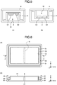
- Fig. 6(a) is a plan view showing a configuration of another reinforcing structure
- Fig. 6(b) is a sectional view taken along line A-A in Fig. 6(a) . As shown in Figs.
- another reinforcing structure 5 is a member disposed so as to extend in the x direction at the central part of the hollow structure S1 in the y direction, and is connected to the flat portion 21 of the bottom cover 2 and the flat portion 31 of the reinforcing structure 3.
- the rising wall member 22 of the bottom cover 2 and the rising wall member 32 of the reinforcing structure 3 are integrated with the other reinforcing structure 5, and thus the rising wall members of the bottom cover 2 and the reinforcing structure 3 are hardly deformed particularly inside direction of the housing 1, so that the torsional rigidity of the housing 1 can be improved.
- the other reinforcing structure 5 may be a member disposed so as to extend in the y direction at the central part of the hollow structure S1 in the x direction, or a member disposed so as to extend in the diagonal direction of the hollow structure S1.
- the other reinforcing structure 5 is disposed so as to pass through a position at which the amount of deflection of the flat portion 21 of the bottom cover 2 increases when a load is applied in the thickness direction, and a plurality of members may be disposed with the members crossing one another.
- the other reinforcing structure 5 is formed of an impact absorbing material excellent in elasticity, such as a resin material having an elastomer or rubber component, or a gel, and accordingly, not only deflection rigidity but also an effect against impact can be exhibited.
- an impact absorbing material excellent in elasticity such as a resin material having an elastomer or rubber component, or a gel
- the reinforcing structure 3 includes the flat portion 31, the rising wall member 32 and the joining portion 33 as shown in Fig. 7(a) , but the reinforcing structure 3 may be formed by using a curved member as the flat portion 31 and forming the joining portion 33 on a rim of the curved member as shown in Fig. 7(b) . That is, a curved member may be used as the flat portion 31, resulting in omission of the rising wall member 32. In addition, from the viewpoint of increasing rigidity and effectively utilizing the space, an irregular shape may be formed on the flat portion 31.
- the reinforcing structure 3 is joined to the bottom cover 2, but the reinforcing structure 3 may be joined to the top cover 4 to form the hollow structure S1 between the flat portion 31 of the reinforcing structure 3 and the top cover 4.
- the joining portion 33 is formed on all of the four rising wall members 32 formed on respective sides of the flat portion 31, but the joining portion 33 may be formed on at least one of the four rising wall members 32. Alternatively, the joining portion 33 may be formed on two or more adjacent rising wall members 32 among the four rising wall members 32. In addition, the area of the joining portion 33 formed on one rising wall member 32 is preferably 1 cm 2 or more.
- the thickness of the member that forms the reinforcing structure 3 is preferably within a range of 0.3 mm or more and 1.0 mm or less from the viewpoint of reducing the weight and thickness of the housing.
- the elastic modulus of the member that forms the reinforcing structure 3 is preferably within a range of 20 GPa or more and 120 GPa or less.
- the reinforcing structure 3 is formed of any one of the above-described metal material and fiber-reinforced composite material, and the material can be selected according to the purpose of the reinforcing structure 3. That is, from the viewpoint of exhibiting a high reinforcing effect, it is preferable to use a metal material or fiber reinforced composite material having a high elastic modulus, and from the viewpoint of heat dissipation, it is preferable to use a metal material having a high thermal conductivity. Further, when the reinforcing structure 3 is formed of a fiber reinforced composite material, it is preferable that the reinforcing structure 3 is composed of a laminate of continuous fiber prepregs. In addition, the ratio of the linear expansion coefficient of the reinforcing structure 3 to the linear expansion coefficient of the bottom cover 2 or the bottom cover 4 to which the reinforcing structure 3 is joined is preferably within a range of 0.1 or more and 10 or less.
- the joining portion 33 of the reinforcing structure 3 is bonded to the flat portion 21 of the bottom cover 2 by thermal welding.
- the peeling load at 23°C is more preferably within a range of 100 N/cm 2 or more and 5000 N/cm 2 or less.
- the thermal welding method may include an insert injection method, an outsert injection method, a vibration welding method, an ultrasonic welding method, a laser welding method and a hot plate welding method.
- the bonding surface between the joining portion 33 and the flat portion 21 has a peeling load of less than 60 N/cm 2 at 200°C.
- the peeling load at 200°C is more preferably 30 N/cm 2 or less.
- this peeling load is preferably less than 60 N/cm 2 at 180°C, and it is preferable from the viewpoint of disassembling adhesive that the peeling load can be easily peeled off in a lower temperature range.
- the reinforcing structure may be peeled off temperature elevation associated with operation of an electronic component or depending on the temperature of a use environment in use as a housing. Therefore, it is preferable that in the temperature range where the housing is used, the reinforcing structure is joined with high bonding strength, and in the disassembling temperature range, the reinforcing structure can be easily peeled off.
- the peeling load at 80°C is more preferably within a range of 60 N/cm 2 or more and 5000 N/cm 2 or less.
- the peeling load at 200°C is preferably as low as possible, and most preferably 10 N/cm 2 or less. Since the peeling load at 200°C is preferably as low as possible, the lower limit thereof is not particularly limited, and is preferably 0 N/cm 2 or more, but the peeling load at 200°C is more preferably 1 N/cm 2 or more because when it is excessively low, handling characteristics may be deteriorated. With this configuration, disassembling bondability that makes it possible to easily remove the reinforcing structure 3 can be exhibited, so that repair and recycling of an electronic device can be facilitated.
- the reinforcing structure 3, and the bottom cover 2 or the top cover 4 to which the reinforcing structure 3 is joined are formed of a fiber-reinforced composite material, a thermoplastic resin is provided in or on a joining portion of at least one of the reinforcing structure 3 and the top cover 4 or the bottom cover 2 to which the reinforcing structure 3 is joined, and the reinforcing structure 3 and the bottom cover 2 or the top cover 4 are joined with the thermoplastic resin, in the above-described invention.
- thermoplastic resin on the joining portion As a method for providing a thermoplastic resin on the joining portion, mention is made of a method in which using a fiber-reinforced sheet (prepreg sheet) including a thermoplastic resin as a matrix resin, molding is performed to obtain the reinforcing structure 3, and the bottom cover 2 or the top cover 4 to which the reinforcing structure 3 is joined.
- preg sheet a fiber-reinforced sheet
- molding is performed to obtain the reinforcing structure 3, and the bottom cover 2 or the top cover 4 to which the reinforcing structure 3 is joined.
- a molded product obtained by this method is preferable because a thermoplastic resin is present on a surface of the molded product at a high ratio, and therefore it is possible to secure a wide bonding area in joining, leading to an increase in selection freedom of a joining site.
- a fiber-reinforced composite material including a thermosetting resin as a matrix resin is preferable, and as a method for providing a thermoplastic resin on such a member, a mention is made of a method in which a molten material obtained by heating and melting a thermoplastic resin or a solution obtained by dissolving a thermoplastic resin in a solvent is applied to provide a thermoplastic resin on the fiber-reinforced composite material.
- preg sheet a fiber-reinforced sheet including a thermosetting resin as a matrix resin
- a laminate in which a film or nonwoven fabric composed of a thermoplastic resin is laminated on a surface is molded under heat and pressure on the outermost layer of the fiber-reinforced sheet (prepreg sheet).
- the reinforcing structure 3 and the bottom cover 2 or the top cover 4 are joined directly.
- a fiber reinforced composite material having a thermoplastic resin is used for the joining portion 33 of the reinforcing structure 3 and/or the joining portion of the bottom cover 2 or the top cover 4 that is bonded to the joining portion 33, it is not necessary to use an adhesive agent other than the members, and the members can be joined directly, so that an increase in weight of the housing 1 can be suppressed.
- a suitable method for directly joining the reinforcing structure 3 and the bottom cover 2 or the top cover 4 is a method using a laminate, in which a film or nonwoven fabric composed of a thermoplastic resin is laminated on a surface, for the outermost layer of a fiber-reinforced sheet (prepreg sheet) including a thermosetting resin as a matrix resin, and the thermoplastic resin used here can also be selected from the group of thermoplastic resins exemplified as the matrix resin.
- thermoplastic resin which has a melting point lower than the molding temperature at which a fiber-reinforced sheet (prepreg sheet) with the matrix resin composed of a thermosetting resin is molded and cured.
- the lower limit of the melting point of the thermoplastic resin is not particularly limited, but it is preferably 80°C or higher, more preferably 100°C or higher from the viewpoint of exhibiting heat resistance in application of the housing of the present invention to an electronic device.
- the form of the thermoplastic resin is not particularly limited, and examples thereof include forms of films, continuous fibers, woven fabrics, particles, nonwoven fabrics and the like, but from the viewpoint of handling characteristics during molding operation, forms of films and nonwoven fabrics are preferable.
- thermoplastic resin By selecting such a resin, the thermoplastic resin is melted during molding, and the thermoplastic resin is formed while spreading like a film over a surface of a molded product, so that the bonding area increases during joining, or the reinforcing fibers of the fiber-reinforced sheet are impregnated with the thermoplastic resin to form a strong thermoplastic resin layer, so that high peeling strength can be exhibited.
- the thermoplastic resin may be provided on at least one of the reinforcing structure 3 obtained in the above-mentioned method and the bottom cover 2 or the top cover 4 joined to the reinforcing structure 3, but it is preferable that the thermoplastic resin is provided on the joining members of both the members to be joined. In addition, it is preferable that substantially the same thermoplastic resin is selected as thermoplastic resins to be provided.
- the "disassembling adhesive” means that the reinforcing structure 3 can be not only easily removed, but also re-bonded, and in re-bonding, the thermoplastic resin may be provided, but it is preferable that the reinforcing structure can be re-bonded without increasing the weight of the thermoplastic resin or the like.
- the peeling load in re-bonding is preferably 50% or more, more preferably 70% or more, of the original peeling load.
- the disassembling adhesive in the present invention can be attained by applying to a joining technique such characteristics of a thermoplastic resin that the resin is melted by heating to reduce dynamic characteristics, and the resin is solidified by cooling or at normal temperature to exhibit high dynamic characteristics specific to the resin.
- a hole can be formed in each of the flat portion 31, the rising wall member 32 and the joining portion 33 of the reinforcing structure 3 to the extent that torsional rigidity in the present invention is improved.
- the hole is disposed to so as to improve the flow of air, e.g. the hole is formed on the opposed rising wall member 32.
- the area of the holes is preferably 30% or less of the surface area of the reinforcing structure 3, and is more desirably 15% or less of the surface area of the reinforcing structure 3 from the viewpoint of torsional rigidity.
- the top cover 4 is joined to the rim of the rising wall member 22 of the bottom cover 2.
- the top cover 4 has a smooth plate shape, but may have a plate shape having a curved surface or irregularities.
- the material and shape of the top cover 4 may be the same as those of the bottom cover 2, and a plurality of reinforcing structures may be disposed and joined in a space by dividing the reinforcing member 3 by the bottom cover 2 and the top cover 4.
- the housing 1 having high rigidity on either of surfaces thereof can be obtained.
- the top cover 4 may be an electronic component such as a liquid crystal display or a keyboard, and with such a configuration, application to a clamshell-type personal computer or a tablet-type personal computer is possible.
- the housing 1 includes: the bottom cover 2; the top cover 4; and the reinforcing structure 3 that is disposed in a space divided by the bottom cover 2 and the top cover 4 and has the flat portion 31, the rising wall member 32 erected on the rim of the flat portion 31, and the joining portion 33 extending from the rim of the rising wall member 32.
- the joining portion 33 of the reinforcing structure 3 is joined to the bottom cover 2 or the top cover 4, the area of the joining portion 33 is within a range of 10 cm 2 or more and 100 cm 2 or less, and the maximum value of the height h of the reinforcing structure 3 is within a range of 3 mm or more and 30 mm or less. Accordingly, there can be provides a housing having improved torsional rigidity while having a reduced thickness and weight.
- the housing according to the second embodiment of the present invention is characterized by a configuration of a reinforcing structure and a projected area of the reinforcing structure.
- Figs. 8(a) and 8(b) are sectional views showing a configuration of a reinforcing structure in a housing according to a second embodiment of the present invention.
- Figs. 9(a) and 9(b) show plan views and sectional views showing projected areas of respective members in the housing according to the second embodiment of the present invention.
- Figs. 10(a) and 10(b) show plan views and sectional views showing an arrangement of the reinforcing structure in the housing according to the second embodiment of the present invention.
- a reinforcing structure 3 includes a reinforcing structure 34 having an opening, and a rim of the reinforcing structure 34 is joined to a bottom cover 2 or a top cover 4 to form a hollow structure S1 as shown in Figs. 8(a) and 8(b) .
- the term "reinforcing structure having an opening” refers to a shape having an opening in a part of the reinforcing structure, and may be a member having a joining portion as described above and shown in Figs. 7(a) and 7(b) . That is, one example of the reinforcing structure having an opening is a reinforcing structure in the first embodiment, i.e.
- a reinforcing structure having a flat portion, a rising wall member erected on a rim of the flat portion, and a joining portion extending from the rim of the rising wall member, or a curved portion, and a joining portion extending from a rim of the curved.
- the projected area S of the reinforcing structure 3 in a direction of the bottom cover 2 or the top cover 4 to which the rim is joined is adjusted within a range of 60% or more and 95% or less of the projected area R of the bottom cover 2 or the top cover 4 to which the rim is jointed as shown in Figs. 9(a) and 9(b).
- Fig. 9(a) shows the projected area R of the bottom cover 2 or the top cover 4
- Fig. 9(b) shows the projected area S of the reinforcing structure 3 when the rim of the reinforcing structure 3 is joined to the bottom cover 2.
- the disposed position of the reinforcing structure 3 is not particularly limited, but it is preferable that the reinforcing structure 3 is positioned equally from the center position C of the bottom cover 2 or the top cover 4 as shown in Fig. 10(a) , and by disposing the reinforcing structure 3 in this manner, torsional rigidity in an x direction or a y direction can be made isotropic.
- the reinforcing structure 3 may be placed on any one of the bottom cover 2 or the top cover 4 as shown in Fig. 10(b) .
- the projected area S is less than 60% of the area of the bottom cover 2 or the top cover 4 to which the reinforcing structure 3 is joined, there arises the problem that the rising wall member that is one factor of exhibiting torsional rigidity in the present invention is formed at a position close to the center position of the bottom cover 2 or the top cover 4, so that original torsional rigidity cannot be exhibited.
- the projected area S is more than 95% of the area of the bottom cover 2 or the top cover 4 to which the reinforcing structure 3 is joined, high torsional rigidity can be exhibited, but there arises the problem that the space S3 becomes small, and therefore it is difficult to dispose electronic components and wiring and the like for forming an electronic device, so that application as a housing is difficult.
- the projected area S of the reinforcing structure 3 in a direction of the bottom cover 2 or the top cover 4 to which the peripheral portion is joined is within a range of 60% or more and 95% or less of the area R of the bottom cover 2 or the top cover 4 to which the rim is joined.
- the projected area of the reinforcing structure 3 in a direction of the bottom cover 2 or the top cover 4 to which the joining portion is joined is preferably within a range of 60% or more and 95% or less of the area of the bottom cover 2 or the top cover 4 to which the joining portion is joined, and therefore, in the present invention, rather than an aspect in which the reinforcing structure 3 and the bottom cover 2 or the top surface cover 4 are joined to each other at a lateral surface, an aspect in which the joining portion of the reinforcing structure 3 is joined to the flat portion of the bottom cover 2 or the top cover 4 as long as, for example, the reinforcing structure 3 has the flat portion, the rising wall member erected on the rim of the flat portion, and the joining portion extending from the rim of the rising wall member, and the bottom cover 2 or the top cover 4 joined to the reinforcing structure 3 has a flat portion.
- the shape of the projected surface of the reinforcing structure 3, i.e. the shape of the flat portion 31 is not particularly limited, and may be not only a rectangular shape, but also a circular shape or a polygonal shape, and from the viewpoint of exhibiting high deflection rigidity, a shape conforming to the shape of the bottom cover 2 and/or the top cover 4 is preferable.
- the shape of the projected surface of the reinforcing structure 3 is preferably a rectangular shape.
- the shape of the projected surface of the reinforcing structure 3 is preferably a shape conforming to the shape of an electronic component to be packed.
- the shape of the projected surface of the reinforcing structure 3 is preferably a shape that is symmetric with respect to an axis in the x direction and/or the y direction.
- the housing 1 includes: the bottom cover 2; the top cover 4; and the reinforcing structure 3 that is disposed in a space divided by the bottom cover 2 and the top cover 4 and has the opening.
- the rim of the reinforcing structure 3 is joined to the bottom cover 2 or the top cover 4, and the projected area of the reinforcing structure 3 in a direction of the bottom cover 2 or the top cover 4 to which the rim of the reinforcing structure 3 is joined is within a range of 60% or more and 95% or less of the area of the bottom cover 2 or the top cover 4 to which the rim of the reinforcing structure 3 is joined. Accordingly, there can be provides a housing having improved torsional rigidity while having a reduced thickness and weight.
- a housing 1 according to the third embodiment of the present invention is characterized by a configuration of a reinforcing structure and a volume of a hollow structure S1 formed by the reinforcing structure.
- a housing 1 according to the third embodiment of the present invention is characterized by a configuration of a reinforcing structure and a volume of a hollow structure S1 formed by the reinforcing structure.
- Figs. 11(a) to 11(c) are sectional views showing spaces in a housing according to a third embodiment of the present invention.
- the reinforcing structure includes a reinforcing structure 34 having an opening, and a rim of the reinforcing structure 34 is joined to a bottom cover 2 or a top cover 4 to form a hollow structure S1 as in the case of the housing according to the second embodiment.
- the volume of the hollow structure S1 formed by the reinforcing structure 3 in the bottom cover 2 shown in Fig. 11 (a) is within a range of 55% or more and 95% or less of the volume of the space S2 divided by the bottom cover 2 and the top cover 4 shown in Fig. 11(b) .
- the volume of the hollow structure S1 is less than 55% of the volume of the space S2
- the projected area of the reinforcing structure 3 is small, so that original torsional rigidity cannot be exhibited.
- the volume of the hollow structure S1 is more than 95% of the volume of the space S2, high torsional rigidity can be exhibited, but there arises the problem that a space S3 as shown in Fig. 11(c) becomes small, and thus it is difficult to dispose electronic components and wiring and the like for forming an electronic device, so that application as a housing is difficult.
- the volume of the hollow structure S1 is within a range of 55% or more and 95% or less of the volume of the space S2 divided by the bottom cover 2 and the top cover 4.
- the housing 1 includes: the bottom cover 2; the top cover 4; and the reinforcing structure 3 that is disposed in a space divided by the bottom cover 2 and the top cover 4 and has the opening.
- the rim of the reinforcing structure 3 is joined to the bottom cover 2 or the top cover 4, and the volume of the hollow structure S1 formed by joining the rim of the reinforcing structure 3 to the bottom cover 2 or the top cover 4 is within a range of 55% or more and 95% or less of the volume S2 divided by the bottom cover 2 and the top cover 4. Accordingly, there can be provides a housing having improved torsional rigidity while having a reduced thickness and weight.
- the housing according to the present invention may be formed by arbitrarily combining the configurations of the housings according to the first, second, and third embodiments.
- the reinforcing structure in the first embodiment may satisfy one or both of the constitutional requirements of the reinforcing structures in the second and third embodiments, or the reinforcing structure in the second embodiment may satisfy the constitutional requirement of the reinforcing structure in the third embodiment.
- other embodiments, examples, operational techniques and the like that are made by those skilled in the art on the basis of the embodiments are all included in the scope of the present invention.
- a housing 1 was fixed in a tester in such a manner that one side of the housing 1 was fixed by a U-shaped fixing tool 100, and the other side opposed to the fixed side was held by a support tool 101 as shown in Fig. 12(a) , the displacement amount of the housing 1 was then measured when a load of 50 N was applied with a change rate set to 1°/min at an angle ⁇ as shown in Fig. 12(b) , and the measured value was defined as a torsional rigidity value of the housing.
- the housing was installed in a tester in such a manner that it was able to apply a tensile load F from the side of a bottom cover 2 or a top cover 4 to which a reinforcing structure was joined.
- "Instron” registered trademark
- Universal Tester Model 4201 manufactured by Instron Co., Ltd.
- the deflection amount of the bottom cover 2 or the top cover 4 was measured when a load of 100 N was applied with the housing 1 pressed at the center position at a cross head speed of 1.0 mm/min using an indenter 102 having a diameter of 20 mm, and the measured value was defined as a deflection rigidity value.
- the peeling load of the reinforcing structure was evaluated in accordance with "Testing methods for tensile strength of adhesive bonds" specified in JIS K6849 (1994).
- housings obtained in examples and comparative examples were used.
- evaluation was performed in a state in which there was not a top cover or bottom cover to which the reinforcing structure was not joined (before the reinforcing structure was joined).
- the bottom cover 2 or the top cover 4 of the housing 1 was fixed by a fixing tool 103
- the reinforcing structure 3 was fixed by a tensile tool 104.
- a tensile load F was applied while each member was fixed, and evaluation was performed until the reinforcing structure 3 was peeled off, or the tensile tool 104 was detached from the reinforcing structure 3.
- the bonding area here was calculated by measuring the width and length of the joining surface of the reinforcing structure 3 before joining. When joining was partially performed, the areas thereof were measured, and summed to determine a joining area.
- the peeling load of the reinforcing structure 3 was calculated from the resulting tensile load value and joining area.
- the housing 1 was placed in a thermostat together with the fixing tool, and the atmospheric temperature in the thermostat was elevated to 200°C. After elevation of the temperature, this state was maintained for 10 minutes, and a tensile load was then applied in the same manner as in the peeling load test of the reinforcing structure 3, and evaluation was performed.
- TORAYCA Prepreg P3252S-12 (manufactured by Toray Industries, Inc.) was provided as material 1. The properties of material 1 are shown in Table 1 below.
- SCF 183 EP-BL 3 manufactured by Super Resin Industry Co., Ltd. was provided as material 2.
- the properties of material 2 are shown in Table 1 below.
- An aluminum alloy A5052 was provided as material 3.
- the properties of material 3 are shown in Table 1 below.
- a magnesium alloy AZ31 was provided as material 4.
- the properties of material 4 are shown in Table 1 below.
- a titanium alloy Ti-6 AI-4V was provided as material 5.
- the properties of material 5 are shown in Table 1 below.
- thermoplastic resin film having a basis weight of 124 g/m 2 was prepared, and provided as material 6.
- the properties of material 6 are shown in Table 1 below.
- Resin pellets of a polycarbonate resin (“Iupilon” (registered trademark) H-4000" manufactured by Mitsubishi Engineering-Plastics Corporation) were provided as material 7. Before molding, the resin pellets were dried for 5 hours using a hot air circulating dryer with the inside temperature set to 120°C. The properties of material 7 are shown in Table 1 below. [Table 1] Material 1 Material 2 Material 3 Material 4 Material 5 Material 6 Material 7 Material - CFRP GFRP Al alloy Mg alloy Ti alloy Ny resin PC resin Elastic modulus GPa 60 25 70 45 113 3.5 2.3 Linear expansion coefficient 10 -6 /°C 0.3 7 23.6 26 8.2 83 65 Thermal conductivity W/m ⁇ K 3.0 0.3 236.0 159.0 22.0 0.3 0.2
- Seven sheets having a predetermined size were cut from material 1. Among them, four sheets were cut in such a manner that the fiber direction of a prepreg was parallel to a longitudinal direction (x direction in Fig. 1 ), and the other three sheets were cut in such a manner that the fiber direction was parallel to a lateral direction (y direction in Fig. 1 ). In this example, the lateral direction (y direction) was set to 0°, and as shown in Fig. 15 , a laminate including seven prepreg sheets was prepared in such a manner that prepreg sheets 105a with the fiber direction set to 90° and prepreg sheets 105b with the fiber direction set to 0° were symmetrically laminated.
- a press molding apparatus and a pair of molds 106 as shown in Fig. 16(a) were used, and the resulting laminate 107 was disposed in a pair of molds 106.
- the heating platen temperature of the press molding apparatus was set to 150°C, and as shown in Fig. 16(b) , the molds 106 were moved, and the laminate was pressurized with the molding pressure kept at 1.0 MPa. After 30 minutes, the molds 106 were opened, and the molded article was removed from the molds 106. Trimming was performed so that the rising wall of the resulting molded article had a desired height, thereby obtaining a bottom cover.
- Example 1-(1) Except that molds configured to prepare a molded article having a smooth shape were used, the same procedure as in Example 1-(1) was carried out to obtain a molded article. Trimming was performed so that the resulting molded article had a desired size, thereby obtaining a top cover.
- Example 1-(1) Except that molds 106 as shown in Fig. 17 were used, the same procedure as in Example 1-(1) was carried out to obtain a molded article. Trimming was performed so that the joining surface of the resulting molded article had a desired width, thereby obtaining a reinforcing structure.
- Example 1 The members obtained in Examples 1-(1) to 1-(3) were joined using an adhesive 108 as shown in Fig. 18 .
- the molding conditions and evaluation results in Example 1 are shown in Table 2 below.
- a bottom cover and a reinforcing structure that were obtained in the same manner as in Examples 1-(1) and 1-(3) were coated with an adhesive at 10 joining portions of the reinforcing structure in such a manner that the joining area at each portion was 6 mm 2 , and the bottom cover and the reinforcing structure were joined to each other. Except for the method for joining, the same procedure as in Examples 1-(1) to 1-(4) was carried out to obtain a housing.
- the molding conditions and evaluation results in Example 4 are shown in Table 2 below.
- Example 5 The molding conditions and evaluation results in Example 5 are shown in Table 3 below.
- Example 1 As another reinforcing structure, 25 sheets of material 1 were laminated so as to have a thickness of 3 mm with 0° prepreg sheets and 90° prepreg sheets being symmetrically laminated in an alternate manner.
- the laminate was heated and pressurized by a press molding apparatus to obtain a molded article.
- the resulting molded article was processed so as to have a height of 7.2 mm, thereby obtaining another reinforcing structure having a size as shown in Table 3.
- the resulting another reinforcing structure was disposed as shown in Fig. 6 , and joined by an adhesive, and subsequently the same procedure as in Examples 1-(1) to 1-(4) to obtain a housing.
- the molding conditions and evaluation results in Example 8 are shown in Table 3 below.
- a flat plate was obtained by injection-molding material 7 with the cylinder temperature and the mold temperature set to 280°C and 100°C, respectively, using molds configured to attain a thickness of 3 mm, and an injection molding machine.
- the resulting flat plate was processed so as to have a width of 7.2 mm, thereby obtaining another reinforcing structure having a size as shown in Table 3. Except that the resulting another reinforcing structure was used, the same procedure as in Example 8 was carried out to obtain a housing.
- the molding conditions and evaluation results in Example 9 are shown in Table 4 below.
- Example 10 Except that a reinforcing structure having a size as described in Table 4 was molded and used, the same procedure as in Examples 1-(1) to 1-(4) was carried out to obtain a housing. The molding conditions and evaluation results in Example 10 are shown in Table 4 below.
- AMILAN polyamide copolymer
- CM8000 manufactured by Toray Industries, Inc.
- Example 12-(1) a film composed of a polyamide copolymer ("AMILAN” (registered trademark) CM8000 manufactured by Toray Industries, Inc.) and having a thickness of 50 ⁇ m was laminated on a surface to be joined to the bottom cover, thereby obtaining a laminate. Except that the resulting laminate was used, the same procedure as in Example 1-(2) was carried out to obtain a top cover.
- AMILAN polyamide copolymer
- CM8000 manufactured by Toray Industries, Inc.
- Example 12-(1) a film composed of a polyamide copolymer ("AMILAN” (registered trademark) CM8000 manufactured by Toray Industries, Inc.) and having a thickness of 50 ⁇ m was laminated on a surface to be joined to the bottom cover, thereby obtaining a laminate. Except that the resulting laminate was used, the same procedure as in Example 1-(3) was carried out to obtain a reinforcing structure.
- AMILAN polyamide copolymer
- CM8000 manufactured by Toray Industries, Inc.
- Example 12-(3) and the bottom cover obtained in Example 12-(1) were superposed on each other in joined form, a joining tool 109 as shown in Fig. 19 was provided, and the joined bottom cover and reinforcing structure were disposed, and heated and pressurized in a press molding apparatus set so that the joining tool 109 had a surface temperature of 180°C.
- the bottom cover 2, the reinforcing structure 3 and the joining tool 109 were taken out from the press molding apparatus, and cooled.
- the joining tool 109 was removed to obtain an integrated product of the bottom cover 2 and the reinforcing structure 3.
- the top cover 4 was joined using an adhesive in the same manner as in Example 1-(4).
- Table 4 The molding conditions and evaluation results in Example 12 are shown in Table 4 below.
- Example 15 A bottom cover and a reinforcing structure that were obtained in the same manner as in Examples 12-(1) and 12-(3) were joined to each other at 10 joining portions of the reinforcing structure by an ultrasonic welding method. Except for the method for joining, the same procedure as in Examples 1-(1) to 1-(4) was carried out to obtain a housing. The molding conditions and evaluation results in Example 15 are shown in Table 5 below.
- Example 16 The molding conditions and evaluation results in Example 16 are shown in Table 5 below.
- Example 8 Except that the other reinforcing structure obtained in Example 8 was used, and the resulting the other reinforcing structure 5, the bottom cover 2 and the reinforcing structure 4 were disposed as shown in Fig. 20 , the same procedure as in Example 12-(4) was carried out to obtain a housing.
- the molding conditions and evaluation results in Example 19 are shown in Table 6 below.
- Example 9 Except that the other reinforcing structure obtained in Example 9 was used, the same procedure as in Example 19 was carried out to obtain a housing.
- the molding conditions and evaluation results in Example 20 are shown in Table 6 below.
- Example 21 Except that a reinforcing structure having a size as described in Table 7 was molded and used, the same procedure as in Examples 12-(1) to 12-(4) was carried out to obtain a housing. The molding conditions and evaluation results in Example 21 are shown in Table 7 below.
- Example 22 Except that as the bottom cover, a material as described in Table 7 was used, the heating platen temperature was 220°C, and the molding pressure was 10 MPa, the same procedure as in Example 1 was carried out to obtain a housing.
- the molding conditions and evaluation results in Example 22 are shown in Table 7 below.
- Example 23 The molding conditions and evaluation results in Example 23 are shown in Table 7 below.
- Example 23 The molding conditions and evaluation results in Example 23 are shown in Table 7 below.
- Example 25 Except that as the bottom cover, a material as described in Table 8 was used, the same procedure as in Example 1 was carried out to obtain a housing. The molding conditions and evaluation results in Example 25 are shown in Table 7 below.
- Example 8 Except that as the reinforcing structure, a material as described in Table 8 was used, the same procedure as in Example 1 was carried out to obtain a housing. The molding conditions and evaluation results in Example 26 are shown in Table 8 below.
- Example 29 The molding conditions and evaluation results in Example 29 are shown in Table 9 below.
- a laminate obtained by laminating 10 sheets of material 6, a press molding apparatus, and a pair of molds 106 as shown in Fig. 16(a) were used.
- the laminate was disposed in a pair of molds 106.
- the heating platen temperature of the press molding apparatus was set to 260°C, and the laminate was pressurized with the molding pressure kept at 1.0 MPa. After 10 minutes, cooling water was made to pass through the heating plate, so that cooling was started.
- the mold temperature decreased to 100°C or lower, the molds 106 were opened, and a molded article was taken out from the molds 106. Trimming was performed so that the rising wall of the resulting molded article had a desired height, thereby obtaining a bottom cover.
- Example 30-(1) Except that the mold to be used was changed so as to attain a size as described in Table 9, the same procedure as in Example 30-(1) was carried out to obtain a reinforcing structure and a top cover.
- Example 30 The molding conditions and evaluation results in Example 30 are shown in Table 9 below.
- Example 12 Except that a size as described in Table 9 was employed, the same procedure as in Example 12 was carried out to obtain a bottom cover and a reinforcing structure. Electronic components were disposed in a hollow structure S1 formed by the bottom cover and the reinforcing structure, and a space S3, and a joining portion was joined by an ultrasonic welding machine in the same manner as in Example 30. In addition, as a top cover, a liquid crystal display was provided, and joined to a bottom member by a double-sided tape. The molding conditions and evaluation results in the electronic device obtained in Reference Example 1 are shown in Table 9 below.
- Example 10 Except that a reinforcing structure was not used, the same procedure as in Example 1 was carried out to obtain a housing.
- the molding conditions and evaluation results in Comparative Example 1 are shown in Table 10 below.
- Comparative Example 2 Except that a laminate obtained by laminating material 1 and material 2 was used as a material of a bottom cover, the same procedure as in Comparative Example 1 was carried out to obtain a housing.
- the molding conditions and evaluation results in Comparative Example 2 are shown in Table 10 below.
- Example 10 Except that a size as described in Table 10 was employed, the same procedure as in Example 1 was carried out to obtain a housing.
- the molding conditions and evaluation results in Comparative Examples 3 and 4 are shown in Table 10 below.
- the housings obtained in examples were confirmed to exhibit high torsional rigidity.
- the housing of Example 1 exhibited very high torsional rigidity, and was also capable of mounting many electronic devices etc. in a hollow structure because the ratio of the hollow structure was high.
- Examples 8 and 9 not only torsional rigidity but also deflection rigidity was exhibited due to the effect of another reinforcing structure.
- an effect was exhibited against not only a static load but also a dynamic load (impact).
- Examples 11 to 21, 29, and 30 are preferable from the viewpoint of repair and recycling because the top cover and the reinforcing structure are joined to each other by heat welding, and therefore the joining portion can be disassembled by heating while high torsional rigidity and deflection rigidity are exhibited.
- Examples 10 to 21, 29, and 30 are preferable from the viewpoint of weight reduction because the reinforcing structure and the bottom cover are bonded directly to each other, and therefore an increase in weight is smaller as compared to a case where an adhesive or a hot melt resin is used.
- Example 22 to 25 and 29 not only high torsional rigidity but also deflection rigidity was exhibited by using a metal material having high dynamic characteristics for the bottom cover.
- the metal material has a high thermal conductivity, and is therefore preferable from the viewpoint of thermal characteristics.
- Example 26 is preferable from the viewpoint of not only high torsional rigidity but also enabling radio wave communication because a non-conductive material having electromagnetic wave permeability is used for the bottom cover.
- Examples 27 and 28 are intended to reduce the thickness of each member, and thus contributes to weight reduction and thickness reduction of the housing while maintaining torsional rigidity.
- Example 30 a resin material was used for each member, and it was confirmed that while having poor deflection rigidity, the housing exhibited torsional rigidity.
- Reference Example 1 was provided as a method for using a housing, where electronic components were disposed in a hollow structure to prepare an electronic device with a liquid crystal display used as a top cover. It was confirmed that when the requirements of the present invention were satisfied, it was possible to provide an electronic device exhibiting high torsional rigidity and deflection rigidity.
- Comparative Examples 1 and 2 had very low resistance to torsion, so that there was the possibility of damaging internal electronic components.
- Comparative Examples 3 and 4 a reinforcing structure was used, but the requirements of the present invention were not satisfied, and it was impossible to exhibit satisfactory torsional rigidity.
- Example 1 Example 2
- Example 3 Example 4
- Bottom cover Material - Material 1 Material 1 Material 1 Material 1 Length mm 210 210 210 Width mm 300 300 300 300 Height mm 10 10 10 Thickness mm 0.8 0.8 0.8 Projected area cm 2 630 630 630 Volume cm 3 572 572 572 572
- Top cover Material - Material 1 Material 1 Material 1 Material 1 Length mm 210 210 210 Width mm 300 300 300 300 Height mm - - - - Thickness mm 0.8 0.8 0.8 0.8 Projected area cm 2 630 630 630 Volume cm 3 - - - - - Reinforcing structure: Material - Material 2 Material 2 Material 2 Material 2 Length mm 200 206 200 200 Width mm 290 296 290 290 Height mm 8 3 2 3
- a housing particularly an electronic device housing in which an electronic device component is built, the housing having improved torsional rigidity while having a reduced thickness and weight.
Landscapes
- Engineering & Computer Science (AREA)
- Theoretical Computer Science (AREA)
- Computer Hardware Design (AREA)
- General Engineering & Computer Science (AREA)
- Human Computer Interaction (AREA)
- General Physics & Mathematics (AREA)
- Physics & Mathematics (AREA)
- Microelectronics & Electronic Packaging (AREA)
- Signal Processing (AREA)
- Chemical & Material Sciences (AREA)
- Materials Engineering (AREA)
- Casings For Electric Apparatus (AREA)
- Telephone Set Structure (AREA)
- Purses, Travelling Bags, Baskets, Or Suitcases (AREA)
Applications Claiming Priority (2)
| Application Number | Priority Date | Filing Date | Title |
|---|---|---|---|
| JP2015185990 | 2015-09-18 | ||
| PCT/JP2016/076121 WO2017047441A1 (fr) | 2015-09-18 | 2016-09-06 | Boîtier |
Publications (3)
| Publication Number | Publication Date |
|---|---|
| EP3352541A1 true EP3352541A1 (fr) | 2018-07-25 |
| EP3352541A4 EP3352541A4 (fr) | 2019-05-15 |
| EP3352541B1 EP3352541B1 (fr) | 2020-08-19 |
Family
ID=58289318
Family Applications (1)
| Application Number | Title | Priority Date | Filing Date |
|---|---|---|---|
| EP16846312.3A Active EP3352541B1 (fr) | 2015-09-18 | 2016-09-06 | Boîtier |
Country Status (7)
| Country | Link |
|---|---|
| US (1) | US10509443B2 (fr) |
| EP (1) | EP3352541B1 (fr) |
| JP (1) | JP6168242B1 (fr) |
| KR (1) | KR20180056650A (fr) |
| CN (1) | CN108029214B (fr) |
| TW (1) | TWI701989B (fr) |
| WO (1) | WO2017047441A1 (fr) |
Families Citing this family (5)
| Publication number | Priority date | Publication date | Assignee | Title |
|---|---|---|---|---|
| US10967585B2 (en) | 2017-03-16 | 2021-04-06 | Guerrilla Industries LLC | Composite structures and methods of forming composite structures |
| KR102479640B1 (ko) * | 2018-02-23 | 2022-12-22 | 삼성전자주식회사 | 액세서리 및 이의 제조 방법 |
| EP3922452A1 (fr) * | 2020-06-08 | 2021-12-15 | LANXESS Deutschland GmbH | Matière composite multicouche |
| US11572124B2 (en) | 2021-03-09 | 2023-02-07 | Guerrilla Industries LLC | Composite structures and methods of forming composite structures |
| US11914431B2 (en) * | 2021-07-22 | 2024-02-27 | Dell Products L.P. | Method of creating mechanical strength and industrial design aesthetics for hinge area of computing devices |
Family Cites Families (18)
| Publication number | Priority date | Publication date | Assignee | Title |
|---|---|---|---|---|
| US4406393A (en) * | 1981-03-23 | 1983-09-27 | Rockwell International Corporation | Method of making filamentary reinforced metallic structures |
| JPS5827997U (ja) * | 1981-08-13 | 1983-02-23 | 株式会社東芝 | 電子機器の放熱構造 |
| DE3412846A1 (de) * | 1984-04-05 | 1985-10-17 | Hoechst Ag, 6230 Frankfurt | Flaechenfoermiger sandwichformkoerper |
| US5024369A (en) * | 1989-05-05 | 1991-06-18 | The United States Of America As Represented By The Secretary Of The Air Force | Method to produce superplastically formed titanium alloy components |
| JPH08288681A (ja) | 1995-04-12 | 1996-11-01 | Hitachi Ltd | 電子機器用筐体およびその製造方法 |
| JPH10150280A (ja) | 1996-11-20 | 1998-06-02 | Kansei Corp | 電気機器のキャビネット構造 |
| JP2000194269A (ja) | 1998-12-28 | 2000-07-14 | Casio Comput Co Ltd | 筐体の構造 |
| JP4254248B2 (ja) * | 2002-04-05 | 2009-04-15 | 株式会社村田製作所 | 電子装置 |
| JP2005317942A (ja) * | 2004-03-29 | 2005-11-10 | Toray Ind Inc | 電気・電子機器 |
| JP2006317942A (ja) | 2006-05-08 | 2006-11-24 | Olympus Corp | 映像表示スクリーン |
| US9283895B2 (en) | 2008-10-31 | 2016-03-15 | Kyoraku Co., Ltd. | Sandwich panel, method of forming core material for sandwich panel, and method of forming sandwich panel |
| JP2011022848A (ja) | 2009-07-16 | 2011-02-03 | Panasonic Corp | 電子機器 |
| DE102010039930A1 (de) | 2010-08-30 | 2012-03-01 | Carl Zeiss Smt Gmbh | Projektionsbelichtungsanlage |
| JP2013074043A (ja) * | 2011-09-27 | 2013-04-22 | Nec Casio Mobile Communications Ltd | 電子機器、及び、補強部材 |
| TWI556937B (zh) | 2012-07-18 | 2016-11-11 | 三菱麗陽股份有限公司 | 纖維強化複合材料構造體與使用該構造體的複合材料成形體 |
| US20140168924A1 (en) | 2012-12-14 | 2014-06-19 | Htc Corporation | Button assembly and handheld electronic device |
| US9713274B2 (en) | 2013-09-18 | 2017-07-18 | Sony Corporation | Electronic apparatus |
| WO2017047440A1 (fr) * | 2015-09-18 | 2017-03-23 | 東レ株式会社 | Boîtier d'appareil électronique |
-
2016
- 2016-09-06 EP EP16846312.3A patent/EP3352541B1/fr active Active
- 2016-09-06 WO PCT/JP2016/076121 patent/WO2017047441A1/fr active Application Filing
- 2016-09-06 JP JP2016561396A patent/JP6168242B1/ja active Active
- 2016-09-06 CN CN201680053861.3A patent/CN108029214B/zh active Active
- 2016-09-06 KR KR1020187007486A patent/KR20180056650A/ko unknown
- 2016-09-06 US US15/760,478 patent/US10509443B2/en active Active
- 2016-09-13 TW TW105129690A patent/TWI701989B/zh active
Also Published As
| Publication number | Publication date |
|---|---|
| EP3352541B1 (fr) | 2020-08-19 |
| JPWO2017047441A1 (ja) | 2017-09-14 |
| JP6168242B1 (ja) | 2017-07-26 |
| US20180260002A1 (en) | 2018-09-13 |
| CN108029214A (zh) | 2018-05-11 |
| CN108029214B (zh) | 2020-07-24 |
| TW201720279A (zh) | 2017-06-01 |
| TWI701989B (zh) | 2020-08-11 |
| US10509443B2 (en) | 2019-12-17 |
| WO2017047441A1 (fr) | 2017-03-23 |
| EP3352541A4 (fr) | 2019-05-15 |
| KR20180056650A (ko) | 2018-05-29 |
Similar Documents
| Publication | Publication Date | Title |
|---|---|---|
| EP3352543B1 (fr) | Boîtier | |
| EP3352540B1 (fr) | Boîtier | |
| EP3352548B1 (fr) | Boîtier d'appareil électronique | |
| EP3352542A1 (fr) | Boîtier | |
| EP3352541B1 (fr) | Boîtier | |
| JP4802802B2 (ja) | 電子機器用筐体 | |
| JP6728607B2 (ja) | 電子機器筐体 | |
| JP6728606B2 (ja) | 電子機器筐体 | |
| JP6736859B2 (ja) | 電子機器筐体 |
Legal Events
| Date | Code | Title | Description |
|---|---|---|---|
| STAA | Information on the status of an ep patent application or granted ep patent |
Free format text: STATUS: THE INTERNATIONAL PUBLICATION HAS BEEN MADE |
|
| PUAI | Public reference made under article 153(3) epc to a published international application that has entered the european phase |
Free format text: ORIGINAL CODE: 0009012 |
|
| STAA | Information on the status of an ep patent application or granted ep patent |
Free format text: STATUS: REQUEST FOR EXAMINATION WAS MADE |
|
| 17P | Request for examination filed |
Effective date: 20180406 |
|
| AK | Designated contracting states |
Kind code of ref document: A1 Designated state(s): AL AT BE BG CH CY CZ DE DK EE ES FI FR GB GR HR HU IE IS IT LI LT LU LV MC MK MT NL NO PL PT RO RS SE SI SK SM TR |
|
| AX | Request for extension of the european patent |
Extension state: BA ME |
|
| DAV | Request for validation of the european patent (deleted) | ||
| DAX | Request for extension of the european patent (deleted) | ||
| A4 | Supplementary search report drawn up and despatched |
Effective date: 20190415 |
|
| RIC1 | Information provided on ipc code assigned before grant |
Ipc: A45C 5/00 20060101ALI20190409BHEP Ipc: H05K 5/02 20060101AFI20190409BHEP Ipc: G06F 1/16 20060101ALI20190409BHEP Ipc: H05K 7/20 20060101ALI20190409BHEP Ipc: H04M 1/02 20060101ALI20190409BHEP |
|
| GRAP | Despatch of communication of intention to grant a patent |
Free format text: ORIGINAL CODE: EPIDOSNIGR1 |
|
| STAA | Information on the status of an ep patent application or granted ep patent |
Free format text: STATUS: GRANT OF PATENT IS INTENDED |
|
| INTG | Intention to grant announced |
Effective date: 20200313 |
|
| GRAS | Grant fee paid |
Free format text: ORIGINAL CODE: EPIDOSNIGR3 |
|
| GRAA | (expected) grant |
Free format text: ORIGINAL CODE: 0009210 |
|
| STAA | Information on the status of an ep patent application or granted ep patent |
Free format text: STATUS: THE PATENT HAS BEEN GRANTED |
|
| AK | Designated contracting states |
Kind code of ref document: B1 Designated state(s): AL AT BE BG CH CY CZ DE DK EE ES FI FR GB GR HR HU IE IS IT LI LT LU LV MC MK MT NL NO PL PT RO RS SE SI SK SM TR |
|
| REG | Reference to a national code |
Ref country code: CH Ref legal event code: EP |
|
| REG | Reference to a national code |
Ref country code: DE Ref legal event code: R096 Ref document number: 602016042484 Country of ref document: DE |
|
| REG | Reference to a national code |
Ref country code: AT Ref legal event code: REF Ref document number: 1305432 Country of ref document: AT Kind code of ref document: T Effective date: 20200915 |
|
| REG | Reference to a national code |
Ref country code: IE Ref legal event code: FG4D |
|
| REG | Reference to a national code |
Ref country code: NL Ref legal event code: FP |
|
| REG | Reference to a national code |
Ref country code: LT Ref legal event code: MG4D |
|
| PG25 | Lapsed in a contracting state [announced via postgrant information from national office to epo] |
Ref country code: LT Free format text: LAPSE BECAUSE OF FAILURE TO SUBMIT A TRANSLATION OF THE DESCRIPTION OR TO PAY THE FEE WITHIN THE PRESCRIBED TIME-LIMIT Effective date: 20200819 Ref country code: HR Free format text: LAPSE BECAUSE OF FAILURE TO SUBMIT A TRANSLATION OF THE DESCRIPTION OR TO PAY THE FEE WITHIN THE PRESCRIBED TIME-LIMIT Effective date: 20200819 Ref country code: SE Free format text: LAPSE BECAUSE OF FAILURE TO SUBMIT A TRANSLATION OF THE DESCRIPTION OR TO PAY THE FEE WITHIN THE PRESCRIBED TIME-LIMIT Effective date: 20200819 Ref country code: BG Free format text: LAPSE BECAUSE OF FAILURE TO SUBMIT A TRANSLATION OF THE DESCRIPTION OR TO PAY THE FEE WITHIN THE PRESCRIBED TIME-LIMIT Effective date: 20201119 Ref country code: GR Free format text: LAPSE BECAUSE OF FAILURE TO SUBMIT A TRANSLATION OF THE DESCRIPTION OR TO PAY THE FEE WITHIN THE PRESCRIBED TIME-LIMIT Effective date: 20201120 Ref country code: FI Free format text: LAPSE BECAUSE OF FAILURE TO SUBMIT A TRANSLATION OF THE DESCRIPTION OR TO PAY THE FEE WITHIN THE PRESCRIBED TIME-LIMIT Effective date: 20200819 Ref country code: NO Free format text: LAPSE BECAUSE OF FAILURE TO SUBMIT A TRANSLATION OF THE DESCRIPTION OR TO PAY THE FEE WITHIN THE PRESCRIBED TIME-LIMIT Effective date: 20201119 Ref country code: PT Free format text: LAPSE BECAUSE OF FAILURE TO SUBMIT A TRANSLATION OF THE DESCRIPTION OR TO PAY THE FEE WITHIN THE PRESCRIBED TIME-LIMIT Effective date: 20201221 |
|
| REG | Reference to a national code |
Ref country code: AT Ref legal event code: MK05 Ref document number: 1305432 Country of ref document: AT Kind code of ref document: T Effective date: 20200819 |
|
| PG25 | Lapsed in a contracting state [announced via postgrant information from national office to epo] |
Ref country code: LV Free format text: LAPSE BECAUSE OF FAILURE TO SUBMIT A TRANSLATION OF THE DESCRIPTION OR TO PAY THE FEE WITHIN THE PRESCRIBED TIME-LIMIT Effective date: 20200819 Ref country code: RS Free format text: LAPSE BECAUSE OF FAILURE TO SUBMIT A TRANSLATION OF THE DESCRIPTION OR TO PAY THE FEE WITHIN THE PRESCRIBED TIME-LIMIT Effective date: 20200819 Ref country code: PL Free format text: LAPSE BECAUSE OF FAILURE TO SUBMIT A TRANSLATION OF THE DESCRIPTION OR TO PAY THE FEE WITHIN THE PRESCRIBED TIME-LIMIT Effective date: 20200819 Ref country code: IS Free format text: LAPSE BECAUSE OF FAILURE TO SUBMIT A TRANSLATION OF THE DESCRIPTION OR TO PAY THE FEE WITHIN THE PRESCRIBED TIME-LIMIT Effective date: 20201219 |
|
| PG25 | Lapsed in a contracting state [announced via postgrant information from national office to epo] |
Ref country code: EE Free format text: LAPSE BECAUSE OF FAILURE TO SUBMIT A TRANSLATION OF THE DESCRIPTION OR TO PAY THE FEE WITHIN THE PRESCRIBED TIME-LIMIT Effective date: 20200819 Ref country code: SM Free format text: LAPSE BECAUSE OF FAILURE TO SUBMIT A TRANSLATION OF THE DESCRIPTION OR TO PAY THE FEE WITHIN THE PRESCRIBED TIME-LIMIT Effective date: 20200819 Ref country code: RO Free format text: LAPSE BECAUSE OF FAILURE TO SUBMIT A TRANSLATION OF THE DESCRIPTION OR TO PAY THE FEE WITHIN THE PRESCRIBED TIME-LIMIT Effective date: 20200819 Ref country code: CZ Free format text: LAPSE BECAUSE OF FAILURE TO SUBMIT A TRANSLATION OF THE DESCRIPTION OR TO PAY THE FEE WITHIN THE PRESCRIBED TIME-LIMIT Effective date: 20200819 Ref country code: DK Free format text: LAPSE BECAUSE OF FAILURE TO SUBMIT A TRANSLATION OF THE DESCRIPTION OR TO PAY THE FEE WITHIN THE PRESCRIBED TIME-LIMIT Effective date: 20200819 |
|
| REG | Reference to a national code |
Ref country code: CH Ref legal event code: PL |
|
| REG | Reference to a national code |
Ref country code: DE Ref legal event code: R097 Ref document number: 602016042484 Country of ref document: DE |
|
| PG25 | Lapsed in a contracting state [announced via postgrant information from national office to epo] |
Ref country code: MC Free format text: LAPSE BECAUSE OF FAILURE TO SUBMIT A TRANSLATION OF THE DESCRIPTION OR TO PAY THE FEE WITHIN THE PRESCRIBED TIME-LIMIT Effective date: 20200819 Ref country code: ES Free format text: LAPSE BECAUSE OF FAILURE TO SUBMIT A TRANSLATION OF THE DESCRIPTION OR TO PAY THE FEE WITHIN THE PRESCRIBED TIME-LIMIT Effective date: 20200819 Ref country code: AT Free format text: LAPSE BECAUSE OF FAILURE TO SUBMIT A TRANSLATION OF THE DESCRIPTION OR TO PAY THE FEE WITHIN THE PRESCRIBED TIME-LIMIT Effective date: 20200819 Ref country code: AL Free format text: LAPSE BECAUSE OF FAILURE TO SUBMIT A TRANSLATION OF THE DESCRIPTION OR TO PAY THE FEE WITHIN THE PRESCRIBED TIME-LIMIT Effective date: 20200819 |
|
| PLBE | No opposition filed within time limit |
Free format text: ORIGINAL CODE: 0009261 |
|
| STAA | Information on the status of an ep patent application or granted ep patent |
Free format text: STATUS: NO OPPOSITION FILED WITHIN TIME LIMIT |
|
| PG25 | Lapsed in a contracting state [announced via postgrant information from national office to epo] |
Ref country code: LU Free format text: LAPSE BECAUSE OF NON-PAYMENT OF DUE FEES Effective date: 20200906 Ref country code: SK Free format text: LAPSE BECAUSE OF FAILURE TO SUBMIT A TRANSLATION OF THE DESCRIPTION OR TO PAY THE FEE WITHIN THE PRESCRIBED TIME-LIMIT Effective date: 20200819 |
|
| 26N | No opposition filed |
Effective date: 20210520 |
|
| PG25 | Lapsed in a contracting state [announced via postgrant information from national office to epo] |
Ref country code: LI Free format text: LAPSE BECAUSE OF NON-PAYMENT OF DUE FEES Effective date: 20200930 Ref country code: IE Free format text: LAPSE BECAUSE OF NON-PAYMENT OF DUE FEES Effective date: 20200906 Ref country code: SI Free format text: LAPSE BECAUSE OF FAILURE TO SUBMIT A TRANSLATION OF THE DESCRIPTION OR TO PAY THE FEE WITHIN THE PRESCRIBED TIME-LIMIT Effective date: 20200819 Ref country code: CH Free format text: LAPSE BECAUSE OF NON-PAYMENT OF DUE FEES Effective date: 20200930 |
|
| PG25 | Lapsed in a contracting state [announced via postgrant information from national office to epo] |
Ref country code: TR Free format text: LAPSE BECAUSE OF FAILURE TO SUBMIT A TRANSLATION OF THE DESCRIPTION OR TO PAY THE FEE WITHIN THE PRESCRIBED TIME-LIMIT Effective date: 20200819 Ref country code: MT Free format text: LAPSE BECAUSE OF FAILURE TO SUBMIT A TRANSLATION OF THE DESCRIPTION OR TO PAY THE FEE WITHIN THE PRESCRIBED TIME-LIMIT Effective date: 20200819 Ref country code: CY Free format text: LAPSE BECAUSE OF FAILURE TO SUBMIT A TRANSLATION OF THE DESCRIPTION OR TO PAY THE FEE WITHIN THE PRESCRIBED TIME-LIMIT Effective date: 20200819 |
|
| PG25 | Lapsed in a contracting state [announced via postgrant information from national office to epo] |
Ref country code: MK Free format text: LAPSE BECAUSE OF FAILURE TO SUBMIT A TRANSLATION OF THE DESCRIPTION OR TO PAY THE FEE WITHIN THE PRESCRIBED TIME-LIMIT Effective date: 20200819 |
|
| PGFP | Annual fee paid to national office [announced via postgrant information from national office to epo] |
Ref country code: IT Payment date: 20220811 Year of fee payment: 7 Ref country code: GB Payment date: 20220728 Year of fee payment: 7 |
|
| PGFP | Annual fee paid to national office [announced via postgrant information from national office to epo] |
Ref country code: BE Payment date: 20220823 Year of fee payment: 7 |
|
| P01 | Opt-out of the competence of the unified patent court (upc) registered |
Effective date: 20230515 |
|
| PGFP | Annual fee paid to national office [announced via postgrant information from national office to epo] |
Ref country code: NL Payment date: 20230816 Year of fee payment: 8 |
|
| PGFP | Annual fee paid to national office [announced via postgrant information from national office to epo] |
Ref country code: FR Payment date: 20230808 Year of fee payment: 8 Ref country code: DE Payment date: 20230802 Year of fee payment: 8 |
|
| GBPC | Gb: european patent ceased through non-payment of renewal fee |
Effective date: 20230906 |