EP3352259B1 - Elektrochemische metall-luft-zelle mit modus mit hoher energieeffizienz - Google Patents
Elektrochemische metall-luft-zelle mit modus mit hoher energieeffizienz Download PDFInfo
- Publication number
- EP3352259B1 EP3352259B1 EP18160582.5A EP18160582A EP3352259B1 EP 3352259 B1 EP3352259 B1 EP 3352259B1 EP 18160582 A EP18160582 A EP 18160582A EP 3352259 B1 EP3352259 B1 EP 3352259B1
- Authority
- EP
- European Patent Office
- Prior art keywords
- electrode
- metal
- fuel
- oxygen
- air
- Prior art date
- Legal status (The legal status is an assumption and is not a legal conclusion. Google has not performed a legal analysis and makes no representation as to the accuracy of the status listed.)
- Active
Links
- QVGXLLKOCUKJST-UHFFFAOYSA-N atomic oxygen Chemical compound [O] QVGXLLKOCUKJST-UHFFFAOYSA-N 0.000 claims description 176
- 229910052760 oxygen Inorganic materials 0.000 claims description 176
- 239000001301 oxygen Substances 0.000 claims description 176
- 239000000446 fuel Substances 0.000 claims description 156
- 229910052751 metal Inorganic materials 0.000 claims description 139
- 239000002184 metal Substances 0.000 claims description 139
- PXHVJJICTQNCMI-UHFFFAOYSA-N Nickel Chemical compound [Ni] PXHVJJICTQNCMI-UHFFFAOYSA-N 0.000 claims description 92
- 230000002441 reversible effect Effects 0.000 claims description 80
- 230000009467 reduction Effects 0.000 claims description 76
- 238000007254 oxidation reaction Methods 0.000 claims description 58
- 230000003647 oxidation Effects 0.000 claims description 54
- 229910052759 nickel Inorganic materials 0.000 claims description 46
- 229910021508 nickel(II) hydroxide Inorganic materials 0.000 claims description 14
- 239000011701 zinc Substances 0.000 claims description 13
- 230000001590 oxidative effect Effects 0.000 claims description 11
- HCHKCACWOHOZIP-UHFFFAOYSA-N Zinc Chemical compound [Zn] HCHKCACWOHOZIP-UHFFFAOYSA-N 0.000 claims description 8
- 238000000034 method Methods 0.000 claims description 8
- 229910052725 zinc Inorganic materials 0.000 claims description 8
- XEEYBQQBJWHFJM-UHFFFAOYSA-N Iron Chemical compound [Fe] XEEYBQQBJWHFJM-UHFFFAOYSA-N 0.000 claims description 6
- 239000008151 electrolyte solution Substances 0.000 claims description 5
- 150000002500 ions Chemical class 0.000 claims description 4
- FYYHWMGAXLPEAU-UHFFFAOYSA-N Magnesium Chemical compound [Mg] FYYHWMGAXLPEAU-UHFFFAOYSA-N 0.000 claims description 3
- 229910052784 alkaline earth metal Inorganic materials 0.000 claims description 3
- 150000001342 alkaline earth metals Chemical class 0.000 claims description 3
- 229910052782 aluminium Inorganic materials 0.000 claims description 3
- XAGFODPZIPBFFR-UHFFFAOYSA-N aluminium Chemical compound [Al] XAGFODPZIPBFFR-UHFFFAOYSA-N 0.000 claims description 3
- 229910052742 iron Inorganic materials 0.000 claims description 3
- 229910052749 magnesium Inorganic materials 0.000 claims description 3
- 239000011777 magnesium Substances 0.000 claims description 3
- WPBNNNQJVZRUHP-UHFFFAOYSA-L manganese(2+);methyl n-[[2-(methoxycarbonylcarbamothioylamino)phenyl]carbamothioyl]carbamate;n-[2-(sulfidocarbothioylamino)ethyl]carbamodithioate Chemical compound [Mn+2].[S-]C(=S)NCCNC([S-])=S.COC(=O)NC(=S)NC1=CC=CC=C1NC(=S)NC(=O)OC WPBNNNQJVZRUHP-UHFFFAOYSA-L 0.000 claims description 3
- 229910001848 post-transition metal Inorganic materials 0.000 claims description 3
- 229910052723 transition metal Inorganic materials 0.000 claims description 3
- 150000003624 transition metals Chemical class 0.000 claims description 3
- 229910002640 NiOOH Inorganic materials 0.000 claims 2
- 210000004027 cell Anatomy 0.000 description 84
- 239000003570 air Substances 0.000 description 78
- 238000006722 reduction reaction Methods 0.000 description 64
- 238000007599 discharging Methods 0.000 description 27
- 238000006243 chemical reaction Methods 0.000 description 23
- -1 zincate ion Chemical class 0.000 description 16
- 239000003792 electrolyte Substances 0.000 description 15
- 230000036647 reaction Effects 0.000 description 15
- BFDHFSHZJLFAMC-UHFFFAOYSA-L nickel(ii) hydroxide Chemical compound [OH-].[OH-].[Ni+2] BFDHFSHZJLFAMC-UHFFFAOYSA-L 0.000 description 12
- FDUPCFUSNVYCBO-UHFFFAOYSA-N O(O)O.[Ni+3] Chemical compound O(O)O.[Ni+3] FDUPCFUSNVYCBO-UHFFFAOYSA-N 0.000 description 10
- XLYOFNOQVPJJNP-UHFFFAOYSA-N water Chemical compound O XLYOFNOQVPJJNP-UHFFFAOYSA-N 0.000 description 9
- 239000000376 reactant Substances 0.000 description 8
- 230000008901 benefit Effects 0.000 description 7
- 230000008878 coupling Effects 0.000 description 7
- 238000010168 coupling process Methods 0.000 description 7
- 238000005859 coupling reaction Methods 0.000 description 7
- XLOMVQKBTHCTTD-UHFFFAOYSA-N Zinc monoxide Chemical compound [Zn]=O XLOMVQKBTHCTTD-UHFFFAOYSA-N 0.000 description 6
- 239000003054 catalyst Substances 0.000 description 6
- 238000010276 construction Methods 0.000 description 6
- 239000000463 material Substances 0.000 description 6
- 150000002739 metals Chemical class 0.000 description 6
- 239000012080 ambient air Substances 0.000 description 5
- 229920000642 polymer Polymers 0.000 description 5
- KWYUFKZDYYNOTN-UHFFFAOYSA-M Potassium hydroxide Chemical compound [OH-].[K+] KWYUFKZDYYNOTN-UHFFFAOYSA-M 0.000 description 4
- 230000005611 electricity Effects 0.000 description 4
- 230000003068 static effect Effects 0.000 description 4
- 230000007704 transition Effects 0.000 description 4
- WSFSSNUMVMOOMR-UHFFFAOYSA-N Formaldehyde Chemical compound O=C WSFSSNUMVMOOMR-UHFFFAOYSA-N 0.000 description 3
- 230000000875 corresponding effect Effects 0.000 description 3
- 238000013461 design Methods 0.000 description 3
- 230000000694 effects Effects 0.000 description 3
- 239000011148 porous material Substances 0.000 description 3
- 239000011787 zinc oxide Substances 0.000 description 3
- OKTJSMMVPCPJKN-UHFFFAOYSA-N Carbon Chemical compound [C] OKTJSMMVPCPJKN-UHFFFAOYSA-N 0.000 description 2
- 239000004698 Polyethylene Substances 0.000 description 2
- 239000004743 Polypropylene Substances 0.000 description 2
- 229910045601 alloy Inorganic materials 0.000 description 2
- 239000000956 alloy Substances 0.000 description 2
- 229910052799 carbon Inorganic materials 0.000 description 2
- 230000001276 controlling effect Effects 0.000 description 2
- 229910052739 hydrogen Inorganic materials 0.000 description 2
- 239000001257 hydrogen Substances 0.000 description 2
- 230000002209 hydrophobic effect Effects 0.000 description 2
- AMWRITDGCCNYAT-UHFFFAOYSA-L hydroxy(oxo)manganese;manganese Chemical compound [Mn].O[Mn]=O.O[Mn]=O AMWRITDGCCNYAT-UHFFFAOYSA-L 0.000 description 2
- 239000007788 liquid Substances 0.000 description 2
- 229910052987 metal hydride Inorganic materials 0.000 description 2
- 150000004681 metal hydrides Chemical class 0.000 description 2
- 229910044991 metal oxide Inorganic materials 0.000 description 2
- 150000004706 metal oxides Chemical class 0.000 description 2
- 238000010943 off-gassing Methods 0.000 description 2
- 239000007800 oxidant agent Substances 0.000 description 2
- 229920000573 polyethylene Polymers 0.000 description 2
- 229920001155 polypropylene Polymers 0.000 description 2
- 229920001343 polytetrafluoroethylene Polymers 0.000 description 2
- 239000004810 polytetrafluoroethylene Substances 0.000 description 2
- 239000000243 solution Substances 0.000 description 2
- 229920002134 Carboxymethyl cellulose Polymers 0.000 description 1
- RYGMFSIKBFXOCR-UHFFFAOYSA-N Copper Chemical compound [Cu] RYGMFSIKBFXOCR-UHFFFAOYSA-N 0.000 description 1
- MYMOFIZGZYHOMD-UHFFFAOYSA-N Dioxygen Chemical compound O=O MYMOFIZGZYHOMD-UHFFFAOYSA-N 0.000 description 1
- UFHFLCQGNIYNRP-UHFFFAOYSA-N Hydrogen Chemical compound [H][H] UFHFLCQGNIYNRP-UHFFFAOYSA-N 0.000 description 1
- 210000004460 N cell Anatomy 0.000 description 1
- 239000004372 Polyvinyl alcohol Substances 0.000 description 1
- 229920002472 Starch Polymers 0.000 description 1
- NVJHHSJKESILSZ-UHFFFAOYSA-N [Co].N1C(C=C2N=C(C=C3NC(=C4)C=C3)C=C2)=CC=C1C=C1C=CC4=N1 Chemical class [Co].N1C(C=C2N=C(C=C3NC(=C4)C=C3)C=C2)=CC=C1C=C1C=CC4=N1 NVJHHSJKESILSZ-UHFFFAOYSA-N 0.000 description 1
- OSOVKCSKTAIGGF-UHFFFAOYSA-N [Ni].OOO Chemical compound [Ni].OOO OSOVKCSKTAIGGF-UHFFFAOYSA-N 0.000 description 1
- 238000009825 accumulation Methods 0.000 description 1
- 230000002378 acidificating effect Effects 0.000 description 1
- 238000007792 addition Methods 0.000 description 1
- 229910052783 alkali metal Inorganic materials 0.000 description 1
- 150000001340 alkali metals Chemical class 0.000 description 1
- 230000004075 alteration Effects 0.000 description 1
- 238000013459 approach Methods 0.000 description 1
- 230000015572 biosynthetic process Effects 0.000 description 1
- 239000003990 capacitor Substances 0.000 description 1
- 239000001768 carboxy methyl cellulose Substances 0.000 description 1
- 235000010948 carboxy methyl cellulose Nutrition 0.000 description 1
- 239000008112 carboxymethyl-cellulose Substances 0.000 description 1
- 239000004020 conductor Substances 0.000 description 1
- 229910052802 copper Inorganic materials 0.000 description 1
- 239000010949 copper Substances 0.000 description 1
- 230000002596 correlated effect Effects 0.000 description 1
- 230000000779 depleting effect Effects 0.000 description 1
- 229910001882 dioxygen Inorganic materials 0.000 description 1
- 238000003487 electrochemical reaction Methods 0.000 description 1
- 239000002659 electrodeposit Substances 0.000 description 1
- 239000003349 gelling agent Substances 0.000 description 1
- 150000004678 hydrides Chemical class 0.000 description 1
- XLYOFNOQVPJJNP-UHFFFAOYSA-M hydroxide Chemical compound [OH-] XLYOFNOQVPJJNP-UHFFFAOYSA-M 0.000 description 1
- 230000007774 longterm Effects 0.000 description 1
- 238000012986 modification Methods 0.000 description 1
- 230000004048 modification Effects 0.000 description 1
- 238000012544 monitoring process Methods 0.000 description 1
- 229910000483 nickel oxide hydroxide Inorganic materials 0.000 description 1
- 230000035515 penetration Effects 0.000 description 1
- 239000012466 permeate Substances 0.000 description 1
- 229920002451 polyvinyl alcohol Polymers 0.000 description 1
- 235000019422 polyvinyl alcohol Nutrition 0.000 description 1
- 238000010248 power generation Methods 0.000 description 1
- 230000005855 radiation Effects 0.000 description 1
- 229910001404 rare earth metal oxide Inorganic materials 0.000 description 1
- 239000011829 room temperature ionic liquid solvent Substances 0.000 description 1
- 239000004065 semiconductor Substances 0.000 description 1
- 239000008107 starch Substances 0.000 description 1
- 235000019698 starch Nutrition 0.000 description 1
- 238000006467 substitution reaction Methods 0.000 description 1
- NWONKYPBYAMBJT-UHFFFAOYSA-L zinc sulfate Chemical compound [Zn+2].[O-]S([O-])(=O)=O NWONKYPBYAMBJT-UHFFFAOYSA-L 0.000 description 1
Images
Classifications
-
- H—ELECTRICITY
- H01—ELECTRIC ELEMENTS
- H01M—PROCESSES OR MEANS, e.g. BATTERIES, FOR THE DIRECT CONVERSION OF CHEMICAL ENERGY INTO ELECTRICAL ENERGY
- H01M12/00—Hybrid cells; Manufacture thereof
- H01M12/08—Hybrid cells; Manufacture thereof composed of a half-cell of a fuel-cell type and a half-cell of the secondary-cell type
-
- H—ELECTRICITY
- H01—ELECTRIC ELEMENTS
- H01M—PROCESSES OR MEANS, e.g. BATTERIES, FOR THE DIRECT CONVERSION OF CHEMICAL ENERGY INTO ELECTRICAL ENERGY
- H01M10/00—Secondary cells; Manufacture thereof
- H01M10/42—Methods or arrangements for servicing or maintenance of secondary cells or secondary half-cells
- H01M10/425—Structural combination with electronic components, e.g. electronic circuits integrated to the outside of the casing
-
- H—ELECTRICITY
- H01—ELECTRIC ELEMENTS
- H01M—PROCESSES OR MEANS, e.g. BATTERIES, FOR THE DIRECT CONVERSION OF CHEMICAL ENERGY INTO ELECTRICAL ENERGY
- H01M10/00—Secondary cells; Manufacture thereof
- H01M10/42—Methods or arrangements for servicing or maintenance of secondary cells or secondary half-cells
- H01M10/44—Methods for charging or discharging
-
- H—ELECTRICITY
- H01—ELECTRIC ELEMENTS
- H01M—PROCESSES OR MEANS, e.g. BATTERIES, FOR THE DIRECT CONVERSION OF CHEMICAL ENERGY INTO ELECTRICAL ENERGY
- H01M16/00—Structural combinations of different types of electrochemical generators
-
- H—ELECTRICITY
- H01—ELECTRIC ELEMENTS
- H01M—PROCESSES OR MEANS, e.g. BATTERIES, FOR THE DIRECT CONVERSION OF CHEMICAL ENERGY INTO ELECTRICAL ENERGY
- H01M4/00—Electrodes
- H01M4/02—Electrodes composed of, or comprising, active material
- H01M4/24—Electrodes for alkaline accumulators
-
- H—ELECTRICITY
- H01—ELECTRIC ELEMENTS
- H01M—PROCESSES OR MEANS, e.g. BATTERIES, FOR THE DIRECT CONVERSION OF CHEMICAL ENERGY INTO ELECTRICAL ENERGY
- H01M4/00—Electrodes
- H01M4/02—Electrodes composed of, or comprising, active material
- H01M4/24—Electrodes for alkaline accumulators
- H01M4/244—Zinc electrodes
-
- H—ELECTRICITY
- H01—ELECTRIC ELEMENTS
- H01M—PROCESSES OR MEANS, e.g. BATTERIES, FOR THE DIRECT CONVERSION OF CHEMICAL ENERGY INTO ELECTRICAL ENERGY
- H01M4/00—Electrodes
- H01M4/02—Electrodes composed of, or comprising, active material
- H01M4/24—Electrodes for alkaline accumulators
- H01M4/32—Nickel oxide or hydroxide electrodes
-
- H—ELECTRICITY
- H01—ELECTRIC ELEMENTS
- H01M—PROCESSES OR MEANS, e.g. BATTERIES, FOR THE DIRECT CONVERSION OF CHEMICAL ENERGY INTO ELECTRICAL ENERGY
- H01M4/00—Electrodes
- H01M4/86—Inert electrodes with catalytic activity, e.g. for fuel cells
- H01M4/8605—Porous electrodes
- H01M4/8615—Bifunctional electrodes for rechargeable cells
-
- H—ELECTRICITY
- H01—ELECTRIC ELEMENTS
- H01M—PROCESSES OR MEANS, e.g. BATTERIES, FOR THE DIRECT CONVERSION OF CHEMICAL ENERGY INTO ELECTRICAL ENERGY
- H01M10/00—Secondary cells; Manufacture thereof
- H01M10/42—Methods or arrangements for servicing or maintenance of secondary cells or secondary half-cells
- H01M10/425—Structural combination with electronic components, e.g. electronic circuits integrated to the outside of the casing
- H01M2010/4271—Battery management systems including electronic circuits, e.g. control of current or voltage to keep battery in healthy state, cell balancing
-
- H—ELECTRICITY
- H01—ELECTRIC ELEMENTS
- H01M—PROCESSES OR MEANS, e.g. BATTERIES, FOR THE DIRECT CONVERSION OF CHEMICAL ENERGY INTO ELECTRICAL ENERGY
- H01M2300/00—Electrolytes
- H01M2300/0002—Aqueous electrolytes
- H01M2300/0014—Alkaline electrolytes
-
- Y—GENERAL TAGGING OF NEW TECHNOLOGICAL DEVELOPMENTS; GENERAL TAGGING OF CROSS-SECTIONAL TECHNOLOGIES SPANNING OVER SEVERAL SECTIONS OF THE IPC; TECHNICAL SUBJECTS COVERED BY FORMER USPC CROSS-REFERENCE ART COLLECTIONS [XRACs] AND DIGESTS
- Y02—TECHNOLOGIES OR APPLICATIONS FOR MITIGATION OR ADAPTATION AGAINST CLIMATE CHANGE
- Y02E—REDUCTION OF GREENHOUSE GAS [GHG] EMISSIONS, RELATED TO ENERGY GENERATION, TRANSMISSION OR DISTRIBUTION
- Y02E60/00—Enabling technologies; Technologies with a potential or indirect contribution to GHG emissions mitigation
- Y02E60/10—Energy storage using batteries
Definitions
- the present invention relates to a metal-air electrochemical cell with a high energy efficiency mode.
- Rechargeable electrochemical cells are designed for charging to store input electrical current as energy, and discharging for outputting or releasing the stored energy as output electrical current.
- such cells may experience charge and discharge periods of varying length. These intervals can range between relatively long periods of time and very short periods of time (i.e., charge/discharge bursts).
- charge/discharge bursts One example is a cell that stores energy from a solar cell field: charging may occur essentially uninterrupted during clear, sunny days, with extended periods of discharge at night, or charge and discharge cycles may be extremely short due to cloud cover interruptions.
- a wind turbine may output uninterrupted power for charging during steady, continuous winds, but the power output may fluctuate if the presence of wind is interrupted.
- US 2004/0146764 discloses a battery construction including a plurality of discharging cells formed by a cathode structure having plurality of relatively small cathode elements on a cathode support structure, and an anode structure having one or more anode-contacting elements on an anode-contacting element support plate.
- a metal-air electrochemical cell for storing electrical energy from a power source and supplying electrical energy to a load, comprising: a plurality of electrodes comprising a fuel electrode comprising a metal fuel and an air electrode for exposure to an oxygen source, wherein an electrode of the plurality other than the fuel electrode comprises a reversible metal capable of reversible oxidation to a reducible species thereof and reduction to an oxidizable species thereof, and wherein an electrode of the plurality other than the fuel electrode has an oxygen evolving functionality; an ionically conductive medium for conducting ions among the plurality of electrodes; a controller configured to operate the cell in the following states: (i) a standard recharge state wherein the power source is coupled to the fuel electrode and the oxygen evolving electrode for applying a potential difference therebetween to cause reduction of a reducible species of the metal fuel on the fuel electrode and evolution of oxygen from the ionically conductive medium at the oxygen evolving electrode; (ii) a standard discharge state where
- a method for operating an electrochemical cell for storing energy from a power source and supplying energy to a load comprising a plurality of electrodes comprising a fuel electrode comprising a metal fuel and an air electrode, wherein an electrode of the plurality other than the fuel electrode comprises a reversible metal capable of reversible oxidation to a reducible species thereof and reduction to an oxidizable species thereof, and wherein an electrode of the plurality other than the fuel electrode has an oxygen evolving functionality; the method comprising: operating the cell in the following states: (i) a standard recharge state wherein the power source is coupled to the fuel electrode and the oxygen evolving electrode for applying a potential difference therebetween to cause reduction of a reducible species of the metal fuel on the fuel electrode and evolution of oxygen from the ionically conductive medium at the oxygen evolving electrode; (ii) a standard discharge state wherein the fuel electrode and the air electrode are coupled to the load such that oxidation of the metal fuel at the fuel electrode
- the present application provides an advantageous cell construction that is tailored to handle both long and short cycles of charge/discharge each in an effective and efficient manner.
- a metal-air electrochemical cell for storing electrical energy from a power source and supplying electrical energy to a load.
- the cell comprises a plurality of electrodes comprising (i) a fuel electrode comprising a metal fuel and (ii) an air electrode for exposure to an oxygen source.
- An electrode of the plurality other than the fuel electrode i.e. the air electrode or an additional electrode] comprises a reversible metal capable of reversible oxidation to a reducible species thereof and reduction to an oxidizable species thereof.
- the reversible metal is a nickel species.
- an electrode of the plurality other than the fuel electrode has an oxygen evolving functionality. For purposes of clarity, the number of electrodes could be two or more, as will be apparent from the embodiments described herein.
- the cell also comprises an ionically conductive medium for conducting ions among the plurality of electrodes.
- a controller is configured to operate the cell in the following states:
- An energy efficiency of the high energy efficiency discharge and recharge states is greater than an energy efficiency of the standard discharge and recharge states, each energy efficiency being the ratio of q ou tV out /q in V in .
- the air electrode, the electrode comprising the reversible metal and the oxygen evolving electrode are the same electrode which is a quad-functional electrode.
- the load is coupled to the fuel electrode and the quad-functional electrode in both the standard and high efficiency discharge states and the power source is coupled to the fuel electrode and the quad-functional electrode in both the standard and high efficiency recharge states.
- the controller includes a regulator coupled to at least the quad-functional electrode to control the potential at the quad-functional electrode for setting its potential anodic of the potential for oxygen reduction during the high efficiency discharge state and cathodic of the potential for oxygen evolution during the high efficiency recharge state.
- an electrode that pays multiple roles such as oxygen evolution during standard re-charge and oxidation/reduction of the reversible metal during high efficiency re-charge/discharge, may be referenced to as the oxygen evolving electrode in reference to its function during standard re-charge and as the electrode comprising the reversible metal in reference to its function during high efficiency re-charge/discharge.
- the present application discloses a metal-air electrochemical cell 10 with a high efficiency mode.
- the cell 10 may have any construction or configuration, and the examples described herein are not intended to be limiting.
- the cell may be constructed in accordance with any one of the following US patent applications: 12/385,217 , 12/385,489 , 12/631,484 , 12/549,617 , 12/776,962 , 12/885,268 , 12/901,410 , 61/177,072 , 61/243,970 , 61/249,917 , 61/301,377 , 61/304,928 , 61/329,278 , 61/334,047 , 61/365,645 , 61/378,021 , 61/394,954 , 61/358,339 and 61/267,240 .
- the cell 10 may be incorporated into a set of cells in series or in parallel, which may comprise a cell system.
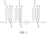
- a set of cells 10 not according to the invention is shown schematically in Figure 1 , and the other Figures also show the cells schematically. It should be understood that one or more such cells 10 may be used in any type of cell system, such as a system of cells stacked in series or in parallel.
- the above cited patent applications provide details of such systems and the construction of the individual cell(s), and those teachings need not be repeated herein.
- Each cell 10 includes a fuel electrode 12 comprising a metal fuel.
- the fuel may be any type of fuel, and is preferably a fuel that may be electrodeposited on a conductive body of the electrode 12.
- a metal fuel may be any type of metal, and the term metal refers to metals in any form, including elemental metals, alloys, metal hydrides, and metals combined in any molecular or complexed form (e.g., oxides).
- the fuel is zinc, but it may also be aluminum, manganese, magnesium, iron, or any other metal selected from the alkaline earth metals, transition metals, or post-transition metals. In some embodiments, alkali metals may be used also.
- the fuel electrode 12 may comprise a single body on which the fuel is reduced/electrodeposited, or it may comprise a series of spaced apart bodies on which the fuel is reduced/electrodeposited progressively or in parallel simultaneously, as discussed in some of the above cited patent applications. Neither approach is intended to be limiting.
- the oxidation half-cell reaction at the fuel electrode 12 during discharge in an alkaline electrolyte may be expressed as: Zn + 4OH - ⁇ Zn(OH) 4 2- + 2e - (1)
- the zincate ion may further react to form zinc oxide as follows: Zn(OH) 4 2 ⁇ ZnO + H 2 O + 2OH - (2)
- the oxidation of zinc to zinc oxide is reversible, and thus these reactions may occur in reverse during re-charge to electrodeposit the zinc on the fuel electrode 12, as will be discussed below, and as is also discussed in the above cited patent applications in detail.
- the metal fuel is a metal hydride
- the reduction/oxidation may be of the hydrogen component of the metal fuel bonded to the metal component.
- Each cell 10 also includes an air electrode 14, also referred to as an air cathode, exposed to an oxygen source.
- the oxygen source is preferably ambient air, and thus the air electrode has a face surface exposed to the ambient air for absorbing the gaseous molecular oxygen (O 2 ) therefrom. This enables the air electrode 14 to reduce the absorbed oxygen to support the electrochemical reactions during the standard discharge mode or state of the cell 10, which will be described below.
- the air electrode 14 is preferably permeable to air, but impermeable to liquid, and particularly the electrolyte solution contained within the cell 10. This allows the air to permeate the body of the air electrode 14, without leakage of the electrolyte therethrough.
- the air electrode 14 is made from a polymer, a catalyst, a catalyst support, and a current conducting material.
- the materials are: polytetrafluoroethylene, polypropylene, or polyethylene for the polymer; nickel, manganese oxide, cobalt porphyrins, or rare earth oxides for the catalyst; and carbon, nickel, and/or copper for the current conducting and/or catalyst support material. Further details concerning the air electrode 14 may be appreciated from the above cited patent applications.
- the reduction half-cell reaction at the air electrode 14 may be expressed as: 2e - + 1 ⁇ 2O 2 + H 2 O ⁇ 2OH - (3)
- the cell 10 also includes an oxygen evolving electrode 16 (also referred to as a charging electrode).
- the oxygen evolving electrode 16 enables oxygen evolution during recharging of the cell 1 0. That is, the oxygen evolving electrode 16 may be held at a potential at which hydroxide ions in the electrolyte are oxidized to form oxygen, which may be off-gassed from the cell 10 or collected and circulated for consumption by the air electrode 14. This is often referred to as water oxidation, as the hydroxide ions are available from water.
- the oxidation half-cell reaction occurring at the oxygen evolving electrode during oxygen evolution during re-charging may be expressed as: 2OH - ⁇ 2e - + 1 ⁇ 2O 2 + H 2 O (4)
- An alkaline electrolyte solution is included in the cell 10 for conducting ions among the electrodes 12, 14, 16, such as potassium hydroxide (KOH) dissolved in water.
- the alkaline electrolyte may be a liquid or a gel. Gelling agents may include, for example, starch, carboxymethyl cellulose, or polyvinyl alcohol crosslinked with formaldehyde. Other electrolytes, such as acidic, non-aqueous, or low or room temperature ionic liquid electrolytes, may be used.
- the cell 10 is enclosed in a housing (not shown) as is well known.
- the electrolyte may be circulated through the cell 10, through a plurality of cells 10 in fluidly connected series, or it may be static and non-flowing. Further details for the management of flow for the electrolyte, if used, may be found in the above cited patent applications.
- a metal-air cell 10 is conventional, as the above-described discharging (i.e., oxidation of metal fuel 12 at the fuel electrode and reduction of oxygen at the air electrode 14) and recharging (i.e., reduction of metal fuel on the fuel electrode 12 and evolution of oxygen at the oxygen evolving electrode 16) are known. These may be referred to as standard discharge and re-charge states or modes of operation, respectively.
- a primary advantage of this conventional cell design and supporting reactions is that oxygen availability is generally not a limiting factor, particularly when the oxygen is derived from ambient air. During re-charging, the evolved oxygen can be off-gassed from the cell 10 relatively easily, so that its accumulation does not retard the re-charging half-cell reaction at the oxygen evolving electrode 16.
- the oxygen may optionally be off-gassed through the air permeable air electrode 14.
- the structure of the air electrode 14 and the oxygen evolving electrode 16 may be constructed with varying pore diameters and varying hydrophobicity such that the off-gassing air bubbles are directed through the air exposed face of the air electrode 14, away from the fuel electrode 12.
- oxygen is readily available, particularly in ambient air, its availability for supporting the half-cell reaction at the air electrode 14 during discharge is not regarded as a limiting factor.
- Energy efficiency is the ratio of q ou tV out /q in V in , where q is the measure of charge stored (in) or withdrawn (out) and V is the potential difference between the relevant electrodes at which the charge is stored or withdrawn.
- energy efficiency is less of an issue than the availability of reactants (energy density). It is during short durations of charge and discharge (i.e., "bursts") that energy efficiency is more of an issue, as the reactants are being consumed/reconstituted at a more frequent rate, and thus availability is less of an issue.
- the field of solar cells may be able to continuously generate energy for 10-14 hours under continual exposure to solar radiation. Some of that energy may be delivered to the power grid, and the excess energy may be stored by the cells 10.
- the cells 10 can be designed such that sufficient fuel is available within the cells 10 to store that excess energy, and the supply of oxygen in ambient air as the oxidant is effectively limitless.
- the cells 10 can be operated to discharge that stored excess energy to a power grid, thus providing electricity derived from the solar cell field even when the solar cells themselves are not generating power.
- the oxygen evolving electrode 16 may comprise (i.e., may include at least one) a metal capable of energy efficient reversible oxidation to a reducible species and reduction to an oxidizable species within the cell 1 0 to support a high energy efficiency mode or state of operation.
- a metal capable of energy efficient reversible oxidation to a reducible species and reduction to an oxidizable species within the cell 1 0 to support a high energy efficiency mode or state of operation This may be referred to as a high energy efficiency metal or reversible metal for convenience.
- the terms oxidizable species and reducible species are used to denote the species or states of the high energy efficiency metal relative to one another and their respective half-cell reactions during re-charge and discharge, as will be discussed below.
- the same definition of metal used above, i.e., including metal oxides, alloys, pure/elemental metals, hydrides, etc. applies equally here to the reversible metal.
- the high energy efficiency metal which is a nickel species
- the high energy efficiency metal is a metal oxide, which may be reversibly oxidized and reduced between states thereof.
- the nickel species may be reversibly oxidized/reduced between nickel (II) hydroxide and nickel (III) oxyhydroxide, and this functionality is used to support the high energy efficiency modes, as will be described below.
- the high energy efficiency metal is supporting short, high frequency bursts of activity, reversibility is highly advantageous and it allows the metal to repeatedly store and discharge energy.
- the high energy efficiency metal e.g., its nickel content, may serve as a surface for supporting the oxidation of hydroxide ions during standard cell charging, off-gassing oxygen as the electrode functions as an oxygen evolving electrode.
- the oxygen evolving electrode may be a porous material made from a polymer and a high efficiency metal.
- the materials are polytetrafluoroethylene, polypropylene, or polyethylene for the polymer; a nickel species for the high energy efficiency metal; and possibly carbon as a support material.
- One or more other metals such as a catalyst metal, may be added to enhance the oxygen evolving functionality, and the relative content/ratio of metals used may be tailored to specific applications as desired. For example, in certain applications it may be desirable to have more of the reversible metal(s) present to store more energy during high efficiency recharging as discussed below, and in other situations less may be needed and it may be more desirable to dedicate more of the active metal component to the oxygen evolving functionality.
- nickel species may be oxidized from nickel(II) hydroxide (its oxidizable species) to nickel (III) oxyhydroxide (its reducible species), which may be expressed as: 2Ni(OH) 2 ⁇ 2NiOOH + 2H + + 2e - (6)
- the hydrogen cations may react with an OH - ion in the electrolyte to form water (H 2 O).
- the oxygen evolving electrode 16 may be used with the nickel (III) oxyhydroxide (its reducible species) being reduced back to nickel (II) hydroxide (its oxidizable species).
- the half-cell reaction at the fuel electrode is above at equation (1), and the half-cell reaction at the oxygen evolving electrode 16 may be expressed as follows: 2NiOOH + 2H + + 2e - ⁇ 2Ni(OH) 2 (7)
- the advantage of this cell design is that the reduction-oxidation of the high energy efficiency nickel species has a high energy efficiency when coupled to the fuel electrode 12, as compared to the oxidation of water/hydroxide ions to evolve oxygen at the oxygen evolving electrode 16 and the reduction of oxygen at the air cathode 14.
- the electrode 16 may be described as being tri-functional, as it can perform the functions of (a) oxidizing hydroxide ions in the electrolyte to evolve oxygen during standard re-charging, (b) oxidizing its own reversible metal during high energy efficiency mode re-charging, and (c) reducing its reversible metal during high energy efficiency mode discharging.
- the energy efficiency is relatively high, in the range of 75% to 95%. More preferably, the energy efficiency is in the range of 80% to 90%, or more preferably it is about 87%.
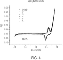
- the asymptotic behavior of the line denotes the domain in which oxygen evolution is occurring during standard re-charging.
- fuel reduction and oxygen evolution occur at a greater potential difference than fuel reduction and nickel species oxidation, because the potential at the oxygen evolving electrode 16 for nickel species oxidation is cathodic of the potential for oxygen evolution.
- the potential difference between fuel oxidation and oxygen reduction (at air cathode 14) during discharge is significantly lower than the potential difference between fuel oxidation and the nickel species reduction (at the oxygen evolving electrode 16), because the nickel species reduction at the oxygen evolving electrode 16 occurs at a potential anodic of the oxygen reduction at the air cathode 12. This means that the energy efficiency is significantly lower for the same amount of charge stored (in) versus drawn (out).
- the fuel electrode 12 and the air electrode 14 are coupled to a load (e.g., the power grid), so that oxidation of the fuel and reduction of the oxygen generates a potential difference applied to the load.
- a power source e.g, solar cells, wind turbines, etc.
- This causes two phases or states of re-charging to occur, with reduction of fuel onto the fuel electrode occurring in both phases.
- the high energy efficiency metal e.g., the nickel species discussed above
- that oxidizable metal species will be oxidized to the reducible species thereof (e.g., nickel (II) hydroxide is oxidized to nickel (III) oxyhydroxide).
- the reducible species thereof e.g., nickel (II) hydroxide is oxidized to nickel (III) oxyhydroxide.
- This may be referred to as a high energy recharge phase or state.
- the oxidation reaction will transition to oxidation of hydroxide ions to evolve oxygen, which may be referred to as a standard recharge phase or state. This occurs because the oxidation of the high energy efficiency metal is typically more facile, and occurs in preference to the evolution of oxygen.
- the phases may be characterized by the oxidation reaction that is predominant (either metal oxidation is occurring more significantly than oxygen evolution, or vice versa).
- the load drawing power is coupled to the fuel electrode 12 and the oxygen evolving electrode 16, so that oxidation of the fuel and reduction of the reducible species of the metal high energy efficiency metal of the oxygen evolving electrode to its oxidizable species (e.g., nickel (III) oxyhydroxide is reduced to nickel(II) hydroxide) generates a potential difference applied to the load.
- the energy efficiency (q out V out /q in V in ) for the standard discharge state and the standard re-charge phase of the recharge state may be in the range of 35% to 65%, and preferably is about 50%.
- the energy efficiency of the high energy efficiency discharge state and the high energy efficiency phase of the re-charge state may be in the range of 75% to 95%, and preferably is at least about 87%.
- the energy efficiency for the high energy efficiency operations is significantly higher than the energy efficiency for the standard operations, preferably by a factor of 1.7, and more preferably by a factor of at least 2.
- This advantage is driven primarily by virtue of there being a smaller difference between the potential differences for the fuel oxidation/nickel (III) oxyhydroxide reduction (V out ) and the fuel reduction/nickel (II) hydroxide oxidation (V in ) than for the fuel oxidation/oxygen reduction (V out ) and the fuel reduction/oxygen evolution (V in ).
- a controller which may include one or more switches 20 for selectively coupling the oxygen evolving electrode 16 or the air cathode 14 to the load during discharging to switch between the standard and high efficiency discharge states, and may also selectively couple the oxygen evolving electrode 16 to the power source for high efficiency and standard recharging.
- the switches 20 may be of any type, including mechanical, semiconductor or any other type of switch.
- a capacitor/auxiliary battery may also be used to provide power/energy between switching from a high energy efficient mode to standard mode during discharge.
- FIG. 1 shows the switches 20 as being simply two-state switches, such as double-pole, single-throw switches.
- the system has opposite output terminals T1 and T2, which may be selectively coupled to a load (during discharge) or a power source (during recharge).
- Each switch has its throw or contact element statically coupled to the subsequent element in the system.
- the contact element of each of the 1 st to N-1th cells would be statically coupled to the subsequent cells, and the contact element of the Nth cell is statically coupled to the terminal T2.
- the contact elements or throws are shown in the normal position for the standard discharge state, coupled to the contact that connects to the air electrode 12.
- the contact elements or throws would be moved to the positions indicated by dashed lines, thus being coupled to the contact that connects to the oxygen evolving electrode 16. This allows the reactions to take place between the fuel electrodes 12 and the oxygen evolving electrodes 16 as discussed above. Any structure may be used, and the illustrated one is shown schematically and is not intended to be limiting.
- the controller determines whether to switch between charging and recharging in general in any suitable matter, and various controls, logics, schemes, and/or algorithms determining predicted or actual power inflow or outflow are known, and need not be detailed herein. With respect to making a determination between standard discharging (fuel electrode - air cathode) and high energy efficiency discharging, any control, logic, scheme and/or algorithm may be used.
- the controller may simply be designed to couple the load to the fuel electrode 12 and oxygen evolving electrode 16 (the high efficiency discharge mode) initially for a period of time during discharge, and then switch to coupling the load to the fuel electrode 12 and the air cathode 14 (the standard discharge mode) in all instances.
- the rationale would be that any subsequent re-charging will initially re-oxidize the high energy efficiency metal during recharging irrespective of whether the power output to the load was for a short or long period of time, and thus there is no need to specifically determine whether the load demand is better suited for high energy or standard discharging.
- the period of time for switching the coupling during discharge may be pre-set, or may be determined by monitoring a voltage, current or power drop indicative of less high energy efficiency metal being available for reduction.
- one or more other parameters may govern whether to couple the load to the air cathode 14 or the oxygen evolving electrode 16 during discharging.
- a clock or timer may provide a signal indicating the time of day, and during the day it can be expected that interruptions in sunlight are likely to be intermittent, whereas at night it is known the lack of sunlight will be continuous.
- the controller may opt during discharge to initially couple the load to the oxygen evolving electrode 16 for a period of time during daylight hours before switching to the air cathode, but skip coupling the load to the oxygen evolving electrode 16 during nighttime hours (what is regarded as daylight and nighttime hours may vary geographically and seasonally).
- controller logic relative to selecting between standard discharging and high energy efficiency discharging are not intended to be limiting.
- the controller may include a microprocessor, or may be made of more basic circuit elements, and no particular type of controller is regarded as limiting.
- the term controller is a generic structural term, and not intended to be limiting.
- the controller need not be limited to a single component, and the controller's operations may be distributed among several components, such as multiple processors, regulators, or circuits, that operate separately from one another or in concert.
- the cell may be in a series of cells electrically coupled together in series.
- the switching arrangements disclosed in U.S. Provisional Application No. 61/243,970 and 12/885,268 may be used to manage the series connections and switching between coupling to the air cathode 14 and the oxygen evolving electrode 16, as well as any bypassing of malfunctioning cells.
- the system of any cell in the embodiment of Figure 1 may also include a current, power, or voltage regulator as part of the controller.
- the regulator may be used to initially maintain the potential of the oxygen evolving electrode 16 during recharging at a level for nickel species oxidation and cathodic of the potential for oxygen evolution to ensure that the high efficiency recharging of the nickel content takes place.
- the nickel species oxidation will take preference to oxygen evolution because it occurs at a lower potential difference.
- an excess amount of power may drive the potential difference higher, causing oxygen evolution to occur instead.
- a regulator may be used for an initial predetermined period at the onset of recharging to maintain the potential of the oxygen evolving electrode at such a level.
- a single current, voltage or power regulator may be coupled to one of the terminals to control the current flow through the cell and/or voltage of the cell, or individual regulators, such as individual voltage regulators, may be associated with each individual cell 10.
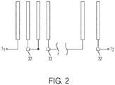
- the separate oxygen evolving electrode is eliminated from the cell 10', and the air electrode 14 has a quad-functional role.
- the quad-functional air electrode 14 is designed to support the functions of (a) oxygen reduction during standard discharging, (b) oxygen evolution during standard re-charging, and (c) oxidation during high energy efficiency discharging, and (d) reduction during high energy efficiency re-charging.
- the electrode 14 may be formed of a polymer to bind the materials and optionally serve as a hydrophobic component, a current conducting component, a catalyst for supporting oxygen reduction, and the reversible or high efficiency metal, such as a high surface area nickel to form nickel (III) oxyhydroxide and nickel (II) hydroxide.
- the electrode may include several porous layers: (a) a hydrophobic air side layer to allow air permeation and prevent electrolyte leakage; (b) a semi-hydrophobic catalyzed active layer for oxygen reduction; (c) a hydrophilic nickel containing layer for oxygen evolution and for formation of nickel (III) oxyhydroxide and nickel (II) hydroxide; (d) a current conducting layer; and (e) a porous hydrophilic layer with pore sizes designed to prevent penetration of oxygen bubbles into the electrolyte gap during oxygen evolution.
- the oxidizable nickel species may be initially oxidized to its reducible species in preference to oxygen as a high efficiency recharge state.
- One example of such oxidation is the reversible oxidization of nickel (II) hydroxide to nickel (III) oxyhydroxide, as discussed above.
- the hydroxide oxidation i.e., oxygen evolution
- the fuel electrode 12 and the air electrode 14 will begin to take place at its more anodic potential as a continued re-charging potential is applied between the fuel electrode 12 and the air electrode 14 as a standard recharge state.
- the reducible nickel species if present, is initially reduced to its oxidizable species in preference to oxygen as a high energy efficiency discharge state, which reduction may be the reversible reduction of nickel oxyhydroxide back to nickel (II) hydroxide, as discussed above.
- the oxygen reduction will begin to take place at a more cathodic potential to continue generating a potential difference between the fuel electrode 12 and the air electrode 14 as a standard discharge state. Because the nickel oxidation and reduction half-cell reactions typically occur in preference to the oxygen oxidation and reduction half-cell reactions, this enables the nickel species to be the reactant opposite the fuel during short burst activity, which enables it to have a higher energy efficiency.
- a regulator 22 such as a voltage regulator, is coupled to the air electrode 14 of each cell 10.
- the voltage regulator is used to control the potential at which the relevant reaction occurs at the air electrode 14.
- the voltage regulator 22 is used to control the potential at the air electrode 14 during discharge, thus selectably controlling whether high efficiency (nickel species reduction) or standard (oxygen reduction) discharging is occurring. This is desirable to ensure that, during periods where standard discharging is preferred, the nickel species is not fully reduced, thus depleting its availability in the event a period of high efficiency recharging/discharging cycles is desired, and also to ensure that the high efficiency nickel species reduction occurs in preference to oxygen reduction during periods when high efficiency discharging is desired.
- the voltage regulators may have any construction and are well known, and the controller may be designed to manage the voltage regulators using the same types of logic, parameter, algorithms, etc. discussed above for controlling the switches in the embodiment of Figure 3 .
- the voltage regulator may also control the electrode 14's potential at which recharging occurs in the event of excess power, as discussed above with respect to the embodiment of Fig. 1 .
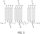
- the cell 10 shown in Fig. 3 , would have (i) the metal fuel electrode 12, (ii) the air electrode 14 for reducing oxygen during standard discharging, (iii) an oxygen evolving electrode 18 for oxidizing hydroxide ions and evolving oxygen during standard re-charging, and (iv) a "high energy efficiency" electrode 19 with a reversibly reducible/oxidizable high energy efficiency metal, such as nickel, capable of energy efficient reversible oxidation and reduction within the cell 10 to support the high energy efficiency discharging and re-charging.
- the functionality of the tri-functional electrode 16 of the first embodiment may be distributed over two separate electrodes, namely the latter two ones 18, 19 mentioned.
- the operation takes place as described above with respect to the first embodiment. That is, the fuel is oxidized at the fuel electrode 12, and oxygen is reduced at the air cathode 14 during a standard discharging state, thus generating a potential difference therebetween for outputting a current to a load.
- a potential from a power source is applied between the fuel electrode 12 and the oxygen evolving electrode 18, thus reducing the reducible fuel species from the electrolyte and electrodepositing it on the fuel electrode, and oxidizing hydroxide ions from the electrolyte to evolve oxygen which may be off-gassed.
- the fuel is still oxidized at the fuel electrode 12, but the corresponding reduction reaction takes place via the reduction of the reducible species of the high energy efficiency metal (e.g., nickel) comprising the high energy efficiency mode electrode 19 to its oxidizable species; thus the potential difference is generated between the fuel electrode 12 and the high energy efficiency mode electrode 19 for outputting a current to a load.
- the high energy efficiency metal e.g., nickel
- this reaction may be the same as described above, namely the reduction of nickel (III) oxyhydroxide to nickel(II) hydroxide.
- a potential from a power source is applied between the fuel electrode 12 and the high energy efficiency mode electrode 19.
- the fuel is reduced from the electrolyte and electrodeposited on the fuel electrode 12, and oxidizable species of the high energy efficiency metal of the high energy efficiency mode electrode 19 is oxidized to its reducible species.
- a nickel species is used as the metal, this reaction may be the same as described above, namely the oxidation of nickel (II) hydroxide to nickel (III) oxyhydroxide.
- the controller may be switched between different states managing these connections and modes/states.
- the embodiment of Fig. 3 includes switches 30 for managing the connections to the air electrode 14, oxygen evolving electrode 18, and high efficiency electrode 19.
- the position of these switches 30 is managed by the controller as discussed above, and the decisions on the states of these switches may be made in a manner similar to that described above with respect to the embodiment of Fig. 1 .
- the switches may have any construction or configuration, and those shown are examples and not intended to be limiting.
- the illustrated switches 30 are each triple pole/single throw switches.
- Each switch 30 has a static contact coupled to contact element/throw and the subsequent element in the circuit; that is, the static contacts for switches for cells 1 to N-1 are coupled to the fuel electrodes 12 of the subsequent cells 10", and the static contact for the Nth cell is coupled to the terminal T2, similarly to the switches in Figure 1 .
- the switches 30 also include three selective contacts, one coupled to the air electrode 14, one coupled to the oxygen evolving electrode 18, and one coupled to the high efficiency electrode 19.
- the contact element/throw connects to the contact for the air electrode 14.
- the contact element/throw connects to the contact for the oxygen evolving electrode 16. In both high efficiency discharging and recharging, the contact element/throw connects to the contact for the high efficiency electrode 19 (the difference being whether the terminals T1 and T2 are coupled to a load or a power source, respectively).
- the embodiment of Figure 3 may also include the bypass switching features mentioned above with respect to Figure 1 , as shown in U.S. Patent Application No. 61/243,970 and 12/885,268 (cited above).
- the embodiment of Figure 3 may also include one or more optional regulators as discussed above with respect to the embodiment of Figure 1 to ensure that excess power delivered during high efficiency recharging does not drive the potential of the high efficiency electrode 19 out of the domain of nickel species oxidation.
- the term “high,” as in “high energy efficiency,” is a relative term meaning the energy efficiency is higher than in the corresponding standard mode, phase or state. Thus, the term “high” should not be taken as a general qualitative term.
Landscapes
- Chemical & Material Sciences (AREA)
- Chemical Kinetics & Catalysis (AREA)
- Electrochemistry (AREA)
- General Chemical & Material Sciences (AREA)
- Engineering & Computer Science (AREA)
- Manufacturing & Machinery (AREA)
- Microelectronics & Electronic Packaging (AREA)
- Hybrid Cells (AREA)
- Inert Electrodes (AREA)
Claims (11)
- Elektrochemische Metall-Luft-Zelle (10) zum Speichern von elektrischer Energie aus einer Leistungsquelle und Zuführen von elektrischer Energie zu einer Last, umfassend:eine Vielzahl von Elektroden, die eine Brennstoffelektrode (12), die einen Metallbrennstoff umfasst, und eine Luftelektrode zur Exposition gegenüber einer Sauerstoffquelle umfassen, wobei eine Elektrode aus der Vielzahl anderer als der Brennstoffelektrode ein reversibles Metall umfasst, das zu einer reversiblen Oxidation einer reduzierbaren Spezies davon und einer Reduktion auf eine oxidierbare Spezies davon geeignet ist, und wobei eine Elektrode aus der Vielzahl anderer als der Brennstoffelektrode eine Sauerstoff entwickelnde Funktionalität aufweist;ein ionisch leitendes Medium zum Leiten von Ionen unter der Vielzahl von Elektroden;eine Steuerung, die konfiguriert ist, um die Zelle in den folgenden Zuständen zu betreiben:(i) einem standardmäßigen Wiederaufladungszustand, wobei die Leistungsquelle mit der Brennstoffelektrode gekoppelt ist und die Sauerstoff entwickelnde Elektrode zum Anwenden einer Potenzialdifferenz, um eine Reduktion einer reduzierbaren Spezies des Metallbrennstoffs auf der Brennstoffelektrode und eine Entwicklung von Sauerstoff aus dem ionisch leitenden Medium an der Sauerstoff entwickelnden Elektrode zu bewirken;(ii) einem standardmäßigen Entladungszustand, wobei die Brennstoffelektrode und die Luftelektrode mit der Last gekoppelt sind, sodass eine Oxidation des Metallbrennstoffs an der Brennstoffelektrode und eine Reduktion von Sauerstoff aus der Sauerstoffquelle an der Luftelektrode eine Potenzialdifferenz zum Ausgeben von Strom erzeugt;(iii) einem Wiederaufladungszustand mit hoher Energieeffizienz, wobei die Leistungsquelle mit der Brennstoffelektrode und der Elektrode gekoppelt ist, die das reversible Metall zum Anwenden einer Potenzialdifferenz umfasst, um eine Reduktion einer reduzierbaren Spezies des Metallbrennstoffs auf der Brennstoffelektrode und das Oxidieren der oxidierbaren Spezies des reversiblen Metalls, falls vorhanden, auf dessen reduzierbare Spezies mit dem Potenzial der Elektrode zu bewirken, die das reversible Metall, das kathodisch ist, des Potenzials zur Sauerstoffentwicklung umfasst; und(iv) einem Entladungszustand mit hoher Energieeffizienz, wobei die Brennstoffelektrode und die Elektrode, die das reversible Metall umfasst, mit der Last gekoppelt sind, sodass eine Oxidation des Metallbrennstoffs an der Brennstoffelektrode und eine Reduktion der reduzierbaren Spezies des reversiblen Metalls, falls vorhanden, auf dessen oxidierbare Spezies eine Potenzialdifferenz zum Ausgeben von Strom mit dem Potenzial des elektrodenreversiblen Metalls, das anodisch ist, des Potenzials zur Sauerstoffreduktion an der Luftelektrode erzeugt;wobei eine Energieeffizienz des Entladungs- und Wiederaufladungszustandes mit hoher Energieeffizienz größer ist als eine Energieeffizienz des standardmäßigen Entladungs- und Wiederaufladungszustandes, wobei jede Energieeffizienz das Verhältnis von qoutVout/qinVin ist;wobei das reversible Metall eine Nickelspezies ist; unddadurch gekennzeichnet, dassdie Luftelektrode, die Elektrode, die das reversible Metall umfasst, und die Sauerstoff entwickelnde Elektrode dieselbe Elektrode sind, sodass die Last sowohl in dem standardmäßigen Entladungszustand als auch in dem Entladungszustand mit hoher Effizienz mit der Brennstoffelektrode und der Luft-/reversiblen Metall-/Sauerstoff entwickelnden Elektrode gekoppelt ist und die Leistungsquelle sowohl in dem standardmäßigen Wiederaufladungszustand als auch in dem Wiederaufladungszustand mit hoher Effizienz mit der Brennstoffelektrode und der Luft-/reversiblen Metall-/Sauerstoff entwickelnden Elektrode gekoppelt ist;dass die Steuerung einen Regulator (22) beinhaltet, der mindestens mit der Luft-/reversiblen Metall-/Sauerstoff entwickelnden Elektrode gekoppelt ist, um das Potenzial an der Luft-/reversiblen Metall-/Sauerstoff entwickelnden Elektrode zum Einstellen ihres Potenzials auf anodisch des Potenzials zur Sauerstoffreduktion während des Entladungszustands mit hoher Effizienz und auf kathodisch des Potenzials zur Sauerstoffentwicklung während des Wiederaufladungszustands mit hoher Effizienz zu steuern.
- Elektrochemische Metall-Luft-Zelle (10) nach Anspruch 1, wobei die oxidierbare Spezies des Nickels Ni(OH)2 ist und die reduzierbare Spezies des Nickels NiOOH ist.
- Elektrochemische Metall-Luft-Zelle (10) nach Anspruch 1, wobei die Steuerung konfiguriert ist, um basierend auf vorbestimmten Kriterien zwischen deren Zuständen zu wechseln.
- Elektrochemische Metall-Luft-Zelle (10) nach einem der Ansprüche 1 bis 3, wobei der Brennstoff ausgewählt wird aus der Gruppe bestehend aus einem Erdalkalimetall, einem Übergangsmetall und einem Nachübergangsmetall.
- Elektrochemische Metall-Luft-Zelle (10) nach einem der Ansprüche 1 bis 3, wobei der Brennstoff ausgewählt wird aus der Gruppe bestehend aus Zink, Aluminium, Magnesium, Mangan und Eisen.
- Elektrochemische Metall-Luft-Zelle (10) nach einem der Ansprüche 1, 2, 4 und 5, wobei das ionisch leitende Medium eine wässrige alkalische Elektrolytlösung ist.
- Verfahren zum Betreiben einer elektrochemischen Zelle (10) zum Speichern von Energie aus einer Leistungsquelle und Zuführen von Energie zu einer Last, wobei die Zelle eine Vielzahl von Elektroden umfasst, die eine Brennstoffelektrode (12) umfasst, die einen Metallbrennstoff und eine Luftelektrode umfasst, wobei eine Elektrode aus der Vielzahl anderer als der Brennstoffelektrode ein reversibles Metall umfasst, das zu einer reversiblen Oxidation einer reduzierbaren Spezies davon und einer Reduktion auf eine oxidierbare Spezies davon geeignet ist, und wobei eine Elektrode aus der Vielzahl anderer als der Brennstoffelektrode eine Sauerstoff entwickelnde Funktionalität aufweist; das Verfahren umfassend:Betreiben der Zelle in den folgenden Zuständen:(i) einem standardmäßigen Wiederaufladungszustand, wobei die Leistungsquelle mit der Brennstoffelektrode und der Sauerstoff entwickelnden Elektrode gekoppelt ist zum Anwenden einer Potenzialdifferenz, um eine Reduktion einer reduzierbaren Spezies des Metallbrennstoffs auf der Brennstoffelektrode und eine Entwicklung von Sauerstoff aus dem ionisch leitenden Medium an der Sauerstoff entwickelnden Elektrode zu bewirken;(ii) einem standardmäßigen Entladungszustand, wobei die Brennstoffelektrode und die Luftelektrode mit der Last gekoppelt sind, sodass eine Oxidation des Metallbrennstoffs an der Brennstoffelektrode und eine Reduktion von Sauerstoff aus der Sauerstoffquelle an der Luftelektrode eine Potenzialdifferenz zum Ausgeben von Strom erzeugt;(iii) einem Wiederaufladungszustand mit hoher Energieeffizienz, wobei die Leistungsquelle mit der Brennstoffelektrode und der Elektrode gekoppelt ist, die das reversible Metall zum Anwenden einer Potenzialdifferenz umfasst, um eine Reduktion einer reduzierbaren Spezies des Metallbrennstoffs auf der Brennstoffelektrode und das Oxidieren der oxidierbaren Spezies des reversiblen Metalls, falls vorhanden, auf dessen reduzierbare Spezies mit dem Potenzial der Elektrode zu bewirken, die das reversible Metall, das kathodisch ist, des Potenzials zur Sauerstoffentwicklung umfasst; und(iv) einem Entladungszustand mit hoher Energieeffizienz, wobei die Brennstoffelektrode und die Elektrode, die das reversible Metall umfasst, mit der Last gekoppelt sind, sodass eine Oxidation des Metallbrennstoffs an der Brennstoffelektrode und eine Reduktion der reduzierbaren Spezies des reversiblen Metalls, falls vorhanden, auf dessen oxidierbare Spezies eine Potenzialdifferenz zum Ausgeben von Strom mit dem Potenzial des elektrodenreversiblen Metalls, das anodisch ist, des Potenzials zur Sauerstoffreduktion an der Luftelektrode erzeugt;wobei eine Energieeffizienz des Entladungs- und Wiederaufladungszustandes mit hoher Energieeffizienz größer ist als eine Energieeffizienz des standardmäßigen Entladungs- und Wiederaufladungszustandes, wobei jede
Energieeffizienz das Verhältnis von qoutVout/qinVin ist;wobei das reversible Metall eine Nickelspezies ist; unddadurch gekennzeichnet, dassdie Luftelektrode, die Elektrode, die das reversible Metall umfasst, und die Sauerstoff entwickelnde Elektrode dieselbe Elektrode sind, sodass die Last sowohl im standardmäßigen als auch im Entladungszustand mit hoher Effizienz mit der Brennstoffelektrode und der Luft-/reversiblen Metall-/Sauerstoff entwickelnden Elektrode gekoppelt ist und die Leistungsquelle mit der Brennstoffelektrode und der Luft-/reversiblen Metall-/Sauerstoff entwickelnden Elektrode gekoppelt ist; unddass ein Regulator (22) mindestens mit der Luft-/reversiblen Metall-/Sauerstoff entwickelnden Elektrode gekoppelt ist, um das Potenzial an der Luft-/reversiblen Metall-/Sauerstoff entwickelnden Elektrode zum Einstellen ihres Potenzials auf anodisch des Potenzials zur Sauerstoffreduktion während des Entladungszustands mit hoher Effizienz und auf kathodisch des Potenzials zur Sauerstoffentwicklung während des Wiederaufladungszustands mit hoher Effizienz zu steuern. - Verfahren nach Anspruch 7, wobei die oxidierbare Spezies des Nickels Ni(OH)2 ist und die reduzierbare Spezies des Nickels NiOOH ist.
- Verfahren nach Anspruch 7, wobei der Brennstoff ausgewählt wird aus der Gruppe bestehend aus einem Erdalkalimetall, einem Übergangsmetall und einem Nachübergangsmetall.
- Verfahren nach Anspruch 7, wobei der Brennstoff ausgewählt wird aus der Gruppe bestehend aus Zink, Aluminium, Magnesium, Mangan und Eisen.
- Verfahren nach Anspruch 7, wobei das ionisch leitende Medium eine wässrige alkalische Elektrolytlösung ist.
Applications Claiming Priority (3)
| Application Number | Priority Date | Filing Date | Title |
|---|---|---|---|
| US32338410P | 2010-04-13 | 2010-04-13 | |
| EP11716118.2A EP2559097B1 (de) | 2010-04-13 | 2011-04-11 | Metall-luft-batteriezelle mit hohem energieeffizienzmodus |
| PCT/US2011/031973 WO2011130178A1 (en) | 2010-04-13 | 2011-04-11 | Metal-air electrocemical cell with high energy efficiency mode |
Related Parent Applications (2)
| Application Number | Title | Priority Date | Filing Date |
|---|---|---|---|
| EP11716118.2A Division EP2559097B1 (de) | 2010-04-13 | 2011-04-11 | Metall-luft-batteriezelle mit hohem energieeffizienzmodus |
| EP11716118.2A Division-Into EP2559097B1 (de) | 2010-04-13 | 2011-04-11 | Metall-luft-batteriezelle mit hohem energieeffizienzmodus |
Publications (2)
| Publication Number | Publication Date |
|---|---|
| EP3352259A1 EP3352259A1 (de) | 2018-07-25 |
| EP3352259B1 true EP3352259B1 (de) | 2020-03-18 |
Family
ID=44123411
Family Applications (2)
| Application Number | Title | Priority Date | Filing Date |
|---|---|---|---|
| EP18160582.5A Active EP3352259B1 (de) | 2010-04-13 | 2011-04-11 | Elektrochemische metall-luft-zelle mit modus mit hoher energieeffizienz |
| EP11716118.2A Not-in-force EP2559097B1 (de) | 2010-04-13 | 2011-04-11 | Metall-luft-batteriezelle mit hohem energieeffizienzmodus |
Family Applications After (1)
| Application Number | Title | Priority Date | Filing Date |
|---|---|---|---|
| EP11716118.2A Not-in-force EP2559097B1 (de) | 2010-04-13 | 2011-04-11 | Metall-luft-batteriezelle mit hohem energieeffizienzmodus |
Country Status (10)
| Country | Link |
|---|---|
| US (2) | US9761920B2 (de) |
| EP (2) | EP3352259B1 (de) |
| CN (2) | CN102918704B (de) |
| AU (1) | AU2011240840A1 (de) |
| BR (1) | BR112012025944A2 (de) |
| CA (1) | CA2795314A1 (de) |
| DK (1) | DK2559097T3 (de) |
| ES (1) | ES2673699T3 (de) |
| TW (1) | TW201222925A (de) |
| WO (1) | WO2011130178A1 (de) |
Families Citing this family (59)
| Publication number | Priority date | Publication date | Assignee | Title |
|---|---|---|---|---|
| US8309259B2 (en) | 2008-05-19 | 2012-11-13 | Arizona Board Of Regents For And On Behalf Of Arizona State University | Electrochemical cell, and particularly a cell with electrodeposited fuel |
| US7820321B2 (en) | 2008-07-07 | 2010-10-26 | Enervault Corporation | Redox flow battery system for distributed energy storage |
| US8785023B2 (en) | 2008-07-07 | 2014-07-22 | Enervault Corparation | Cascade redox flow battery systems |
| JP5734989B2 (ja) | 2009-10-08 | 2015-06-17 | フルイディック, インク.Fluidic, Inc. | 流れ管理システムを備えた電気化学電池 |
| EP3352259B1 (de) | 2010-04-13 | 2020-03-18 | NantEnergy, Inc. | Elektrochemische metall-luft-zelle mit modus mit hoher energieeffizienz |
| JP5788502B2 (ja) | 2010-06-24 | 2015-09-30 | フルイディック, インク.Fluidic, Inc. | 階段状スキャフォールド燃料アノードを備える電気化学セル |
| WO2012012364A1 (en) | 2010-07-19 | 2012-01-26 | Fluidic, Inc. | Electrochemical cell with catch tray |
| CN102456934B (zh) | 2010-10-20 | 2016-01-20 | 流体公司 | 针对基架燃料电极的电池重置过程 |
| JP5908251B2 (ja) | 2010-11-17 | 2016-04-26 | フルイディック,インク.Fluidic,Inc. | 階層型アノードのマルチモード充電 |
| CN202737060U (zh) | 2011-02-04 | 2013-02-13 | 流体公司 | 用于离子导电介质的分散系统、电化学电池系统和外壳 |
| US8916281B2 (en) | 2011-03-29 | 2014-12-23 | Enervault Corporation | Rebalancing electrolytes in redox flow battery systems |
| US8980484B2 (en) | 2011-03-29 | 2015-03-17 | Enervault Corporation | Monitoring electrolyte concentrations in redox flow battery systems |
| US10326144B2 (en) | 2011-07-19 | 2019-06-18 | Nantenergy, Inc. | Hygrophobic conductor layer for electrochemical cell |
| US9214708B2 (en) | 2011-08-05 | 2015-12-15 | Fluidic, Inc. | Gas vent for electrochemical cell |
| US9444105B2 (en) | 2011-11-04 | 2016-09-13 | Fluidic, Inc. | Immersible gaseous oxidant cathode for electrochemical cell system |
| US9269996B2 (en) | 2011-11-04 | 2016-02-23 | Fluidic, Inc. | Filter for electrochemical cell |
| US9413048B2 (en) | 2011-11-04 | 2016-08-09 | Fluidic, Inc. | Air cathode with graphite bonding/barrier layer |
| WO2013110097A1 (en) * | 2012-01-26 | 2013-08-01 | Guillonnet, Didier | Electrically rechargeable metal-air alkaline battery, and method for manufacturing said battery |
| WO2014124386A1 (en) | 2013-02-11 | 2014-08-14 | Fluidic, Inc. | Water recapture/recycle system in electrochemical cells |
| ES2689668T3 (es) | 2013-03-13 | 2018-11-15 | Nantenergy, Inc. | Aditivos sinérgicos para celdas electroquímicas con combustible electrodepositado |
| US9269998B2 (en) | 2013-03-13 | 2016-02-23 | Fluidic, Inc. | Concave gas vent for electrochemical cell |
| CN105210164B (zh) | 2013-03-13 | 2019-02-19 | 南特能源公司 | 用于包括金属燃料的电化学电池的杂离子芳族添加剂 |
| JP6474725B2 (ja) * | 2013-08-01 | 2019-02-27 | シャープ株式会社 | 金属電極カートリッジおよび金属空気電池 |
| CA2927435A1 (en) | 2013-10-14 | 2015-04-23 | Fluidic, Inc. | Method of operating and conditioning electrochemical cells comprising electrodeposited fuel |
| WO2015123290A1 (en) | 2014-02-12 | 2015-08-20 | Fluidic, Inc. | Method of operating electrochemical cells comprising electrodeposited fuel |
| US9696782B2 (en) | 2015-02-09 | 2017-07-04 | Microsoft Technology Licensing, Llc | Battery parameter-based power management for suppressing power spikes |
| US10158148B2 (en) | 2015-02-18 | 2018-12-18 | Microsoft Technology Licensing, Llc | Dynamically changing internal state of a battery |
| US9748765B2 (en) | 2015-02-26 | 2017-08-29 | Microsoft Technology Licensing, Llc | Load allocation for multi-battery devices |
| EP3271957B1 (de) | 2015-03-19 | 2019-04-24 | NantEnergy, Inc. | Batteriezelle mit einem galvanisch abgeschiedenen brennstoff |
| WO2016160418A1 (en) | 2015-03-30 | 2016-10-06 | Fluidic, Inc. | Water management system in electrochemical cells with vapor return comprising air electrodes |
| WO2016197109A1 (en) | 2015-06-04 | 2016-12-08 | Fluidic, Inc. | Hybrid electrochemical cell systems and methods of operation |
| US9939862B2 (en) | 2015-11-13 | 2018-04-10 | Microsoft Technology Licensing, Llc | Latency-based energy storage device selection |
| US10061366B2 (en) | 2015-11-17 | 2018-08-28 | Microsoft Technology Licensing, Llc | Schedule-based energy storage device selection |
| US9793570B2 (en) * | 2015-12-04 | 2017-10-17 | Microsoft Technology Licensing, Llc | Shared electrode battery |
| CN105789738B (zh) * | 2016-04-29 | 2018-08-28 | 清华大学 | 一种等效三电极结构的锌-空气电池 |
| CN109313235B (zh) * | 2016-06-22 | 2021-07-06 | 株式会社村田制作所 | 组电池电路、容量系数检测方法 |
| AU2017298994B2 (en) | 2016-07-22 | 2019-09-12 | Nantenergy, Inc. | Moisture and carbon dioxide management system in electrochemical cells |
| BR112018074575B1 (pt) | 2016-07-22 | 2023-01-17 | Nantenergy, Inc | Célula eletroquímica |
| BR112019004880A2 (pt) | 2016-09-15 | 2019-06-11 | Nantenergy, Inc. | sistema de bateria híbrida |
| MX2019004545A (es) | 2016-10-21 | 2019-11-12 | Nantenergy Inc | Electrodo de combustible corrugado. |
| CN108172953A (zh) * | 2016-12-07 | 2018-06-15 | 中国科学院大连化学物理研究所 | 一种锌空气电池及锌空气电池组 |
| WO2018112510A1 (en) | 2016-12-22 | 2018-06-28 | Hydra Light International Ltd | Metal-air fuel cell |
| WO2018187561A1 (en) | 2017-04-06 | 2018-10-11 | Jaramillo Mateo Cristian | Refuelable battery for the electric grid and method of using thereof |
| JP2020512793A (ja) | 2017-04-09 | 2020-04-23 | ナントエナジー,インク. | 再充電可能電気化学セルを使用した高速切り替えバックアップ電力供給システム |
| FR3068827B1 (fr) * | 2017-07-10 | 2021-11-05 | Electricite De France | Procede de gestion de l'energie electrique transitant dans une batterie metal-air et cellule associee |
| FR3068828B1 (fr) | 2017-07-10 | 2021-04-16 | Electricite De France | Procede de gestion de la puissance electrique transitant par une cellule de batterie metal-air et cellule associee |
| US11611115B2 (en) | 2017-12-29 | 2023-03-21 | Form Energy, Inc. | Long life sealed alkaline secondary batteries |
| EP3815167A4 (de) | 2018-06-29 | 2022-03-16 | Form Energy, Inc. | Wässrige poylsulfidbasierte elektrochemische zelle |
| CN112805868A (zh) | 2018-06-29 | 2021-05-14 | 福恩能源公司 | 金属空气电化学电池构架 |
| EP3815172A4 (de) | 2018-06-29 | 2022-03-09 | Form Energy, Inc. | Rollmembrandichtung |
| CA3105128A1 (en) | 2018-07-27 | 2020-01-30 | Form Energy, Inc. | Negative electrodes for electrochemical cells |
| CN109786762B (zh) * | 2019-01-17 | 2021-01-19 | 北京化工大学 | 一种梯度亲疏水/气空气电极的结构及其制备方法 |
| US11424484B2 (en) | 2019-01-24 | 2022-08-23 | Octet Scientific, Inc. | Zinc battery electrolyte additive |
| WO2020231718A1 (en) | 2019-05-10 | 2020-11-19 | Nantenergy, Inc. | Nested annular metal-air cell and systems containing same |
| EP3991234A4 (de) | 2019-06-28 | 2024-01-17 | Form Energy, Inc. | Gerätearchitekturen für metall-luft-batterien |
| US12294086B2 (en) | 2019-07-26 | 2025-05-06 | Form Energy, Inc. | Low cost metal electrodes |
| US11949129B2 (en) | 2019-10-04 | 2024-04-02 | Form Energy, Inc. | Refuelable battery for the electric grid and method of using thereof |
| EP4147296A4 (de) | 2020-05-06 | 2025-08-13 | Form Energy Inc | Elektrochemisches energiespeichersystem mit entkoppelter elektrode |
| CN116073035A (zh) * | 2022-12-23 | 2023-05-05 | 北京化工大学 | 智能驱动可充电燃料电池 |
Family Cites Families (22)
| Publication number | Priority date | Publication date | Assignee | Title |
|---|---|---|---|---|
| US3883368A (en) | 1972-10-26 | 1975-05-13 | Union Carbide Corp | Alkaline aluminum-air/zinc-manganese dioxide hybrid battery |
| US5250370A (en) | 1992-07-23 | 1993-10-05 | Faris Sades M | Variable area dynamic battery |
| US6451463B1 (en) * | 1997-10-06 | 2002-09-17 | Reveo, Inc. | Electro-chemical power generation systems employing arrays of electronically-controllable discharging and/or recharging cells within a unity support structure |
| US6127061A (en) * | 1999-01-26 | 2000-10-03 | High-Density Energy, Inc. | Catalytic air cathode for air-metal batteries |
| JP2005509244A (ja) | 2001-04-24 | 2005-04-07 | レベオ, インコーポレイティッド | ハイブリッド型電気化学セルシステム |
| US20040014676A1 (en) * | 2001-07-09 | 2004-01-22 | Ramalinga Dharanipragada | SRC kinase inhibitors useful for treating osteoporosis |
| US6998184B2 (en) * | 2003-08-07 | 2006-02-14 | Texaco Ovonic Fuel Cell, Llc | Hybrid fuel cell |
| CN100544087C (zh) * | 2004-06-22 | 2009-09-23 | 旭硝子株式会社 | 固体高分子型燃料电池用电解质膜及其制造方法以及固体高分子型燃料电池用膜电极接合体 |
| US7638216B2 (en) * | 2005-12-21 | 2009-12-29 | General Electric Company | Fuel cell apparatus and associated method |
| WO2007100035A1 (ja) * | 2006-03-03 | 2007-09-07 | Nec Corporation | 電源システム |
| US8168337B2 (en) | 2008-04-04 | 2012-05-01 | Arizona Board Of Regents For And On Behalf Of Arizona State University | Electrochemical cell, and particularly a metal fueled cell with non-parallel flow |
| US8309259B2 (en) | 2008-05-19 | 2012-11-13 | Arizona Board Of Regents For And On Behalf Of Arizona State University | Electrochemical cell, and particularly a cell with electrodeposited fuel |
| US8491763B2 (en) | 2008-08-28 | 2013-07-23 | Fluidic, Inc. | Oxygen recovery system and method for recovering oxygen in an electrochemical cell |
| US20100316935A1 (en) | 2008-12-05 | 2010-12-16 | Fluidic, Llc | Electrochemical cells connected in fluid flow series |
| TWI484683B (zh) | 2009-05-11 | 2015-05-11 | Univ Arizona | 金屬-空氣低溫離子液體電池 |
| WO2011035176A1 (en) | 2009-09-18 | 2011-03-24 | Fluidic, Inc. | Rechargeable electrochemical cell system with a charging electrode charge/discharge mode switching in the cells |
| JP5734989B2 (ja) | 2009-10-08 | 2015-06-17 | フルイディック, インク.Fluidic, Inc. | 流れ管理システムを備えた電気化学電池 |
| US8632921B2 (en) | 2010-02-04 | 2014-01-21 | Fluidic, Inc. | Electrochemical cell with diffuser |
| CN102844932A (zh) | 2010-02-16 | 2012-12-26 | 流体公司 | 电化学电池以及特别是利用电沉积燃料的电池 |
| EP3352259B1 (de) | 2010-04-13 | 2020-03-18 | NantEnergy, Inc. | Elektrochemische metall-luft-zelle mit modus mit hoher energieeffizienz |
| JP5788502B2 (ja) | 2010-06-24 | 2015-09-30 | フルイディック, インク.Fluidic, Inc. | 階段状スキャフォールド燃料アノードを備える電気化学セル |
| US9048028B2 (en) | 2013-03-15 | 2015-06-02 | G4 Synergetics, Inc. | Hybrid electrochemical cell systems and methods |
-
2011
- 2011-04-11 EP EP18160582.5A patent/EP3352259B1/de active Active
- 2011-04-11 ES ES11716118.2T patent/ES2673699T3/es active Active
- 2011-04-11 CN CN201180026382.XA patent/CN102918704B/zh not_active Expired - Fee Related
- 2011-04-11 AU AU2011240840A patent/AU2011240840A1/en not_active Abandoned
- 2011-04-11 US US13/083,929 patent/US9761920B2/en active Active
- 2011-04-11 CA CA2795314A patent/CA2795314A1/en not_active Abandoned
- 2011-04-11 WO PCT/US2011/031973 patent/WO2011130178A1/en not_active Ceased
- 2011-04-11 DK DK11716118.2T patent/DK2559097T3/en active
- 2011-04-11 BR BR112012025944A patent/BR112012025944A2/pt not_active IP Right Cessation
- 2011-04-11 EP EP11716118.2A patent/EP2559097B1/de not_active Not-in-force
- 2011-04-12 TW TW100112682A patent/TW201222925A/zh unknown
- 2011-04-13 CN CN2011201185539U patent/CN202205866U/zh not_active Expired - Lifetime
-
2016
- 2016-01-12 US US14/993,387 patent/US20160156082A1/en not_active Abandoned
Non-Patent Citations (1)
| Title |
|---|
| None * |
Also Published As
| Publication number | Publication date |
|---|---|
| BR112012025944A2 (pt) | 2017-03-28 |
| US9761920B2 (en) | 2017-09-12 |
| EP3352259A1 (de) | 2018-07-25 |
| US20160156082A1 (en) | 2016-06-02 |
| US20110250512A1 (en) | 2011-10-13 |
| WO2011130178A1 (en) | 2011-10-20 |
| CA2795314A1 (en) | 2011-10-20 |
| AU2011240840A1 (en) | 2012-11-01 |
| EP2559097B1 (de) | 2018-05-30 |
| CN102918704A (zh) | 2013-02-06 |
| CN102918704B (zh) | 2016-02-17 |
| EP2559097A1 (de) | 2013-02-20 |
| ES2673699T3 (es) | 2018-06-25 |
| CN202205866U (zh) | 2012-04-25 |
| TW201222925A (en) | 2012-06-01 |
| DK2559097T3 (en) | 2018-06-25 |
Similar Documents
| Publication | Publication Date | Title |
|---|---|---|
| EP3352259B1 (de) | Elektrochemische metall-luft-zelle mit modus mit hoher energieeffizienz | |
| EP2795709B1 (de) | Flussbatteriesystem mit standby-modus | |
| US9595730B2 (en) | Flow battery and usage thereof | |
| EA011752B1 (ru) | Электрод, способ его изготовления, металловоздушный топливный элемент и металлогидридный элемент | |
| Pan et al. | Preliminary study of alkaline single flowing Zn–O2 battery | |
| EP2869383B1 (de) | Stromspeichervorrichtung mit sehr hoher kapazität | |
| US8692517B2 (en) | Non-diffusion liquid energy storage device | |
| Arai | Metal Storage/Metal Air (Zn, Fe, Al, Mg) | |
| EP3089244B1 (de) | Elektrochemische aluminium-manganoxid-zelle | |
| Hahn et al. | Lifetime of the Gas Evolution Electrode of the Zn–H2 Storage System | |
| US11398657B2 (en) | Method for managing the electric power passing through a metal-air battery cell and associated cell | |
| US9343735B2 (en) | Shared electrode hybrid battery-fuel cell system | |
| JP6874806B2 (ja) | 水溶液系二次電池および水溶液系二次電池システム | |
| MX2007014546A (es) | Celda de combustible en polvo. | |
| JP2008010312A (ja) | 発電、および、充放電が可能な燃料電池 |
Legal Events
| Date | Code | Title | Description |
|---|---|---|---|
| PUAI | Public reference made under article 153(3) epc to a published international application that has entered the european phase |
Free format text: ORIGINAL CODE: 0009012 |
|
| STAA | Information on the status of an ep patent application or granted ep patent |
Free format text: STATUS: THE APPLICATION HAS BEEN PUBLISHED |
|
| AC | Divisional application: reference to earlier application |
Ref document number: 2559097 Country of ref document: EP Kind code of ref document: P |
|
| AK | Designated contracting states |
Kind code of ref document: A1 Designated state(s): AL AT BE BG CH CY CZ DE DK EE ES FI FR GB GR HR HU IE IS IT LI LT LU LV MC MK MT NL NO PL PT RO RS SE SI SK SM TR |
|
| RAP1 | Party data changed (applicant data changed or rights of an application transferred) |
Owner name: NANTENERGY, INC. |
|
| STAA | Information on the status of an ep patent application or granted ep patent |
Free format text: STATUS: REQUEST FOR EXAMINATION WAS MADE |
|
| 17P | Request for examination filed |
Effective date: 20190125 |
|
| RBV | Designated contracting states (corrected) |
Designated state(s): AL AT BE BG CH CY CZ DE DK EE ES FI FR GB GR HR HU IE IS IT LI LT LU LV MC MK MT NL NO PL PT RO RS SE SI SK SM TR |
|
| STAA | Information on the status of an ep patent application or granted ep patent |
Free format text: STATUS: EXAMINATION IS IN PROGRESS |
|
| 17Q | First examination report despatched |
Effective date: 20190508 |
|
| GRAP | Despatch of communication of intention to grant a patent |
Free format text: ORIGINAL CODE: EPIDOSNIGR1 |
|
| STAA | Information on the status of an ep patent application or granted ep patent |
Free format text: STATUS: GRANT OF PATENT IS INTENDED |
|
| INTG | Intention to grant announced |
Effective date: 20191127 |
|
| GRAS | Grant fee paid |
Free format text: ORIGINAL CODE: EPIDOSNIGR3 |
|
| GRAA | (expected) grant |
Free format text: ORIGINAL CODE: 0009210 |
|
| STAA | Information on the status of an ep patent application or granted ep patent |
Free format text: STATUS: THE PATENT HAS BEEN GRANTED |
|
| AC | Divisional application: reference to earlier application |
Ref document number: 2559097 Country of ref document: EP Kind code of ref document: P |
|
| AK | Designated contracting states |
Kind code of ref document: B1 Designated state(s): AL AT BE BG CH CY CZ DE DK EE ES FI FR GB GR HR HU IE IS IT LI LT LU LV MC MK MT NL NO PL PT RO RS SE SI SK SM TR |
|
| REG | Reference to a national code |
Ref country code: GB Ref legal event code: FG4D |
|
| REG | Reference to a national code |
Ref country code: DE Ref legal event code: R096 Ref document number: 602011065770 Country of ref document: DE |
|
| REG | Reference to a national code |
Ref country code: AT Ref legal event code: REF Ref document number: 1246965 Country of ref document: AT Kind code of ref document: T Effective date: 20200415 Ref country code: IE Ref legal event code: FG4D |
|
| PG25 | Lapsed in a contracting state [announced via postgrant information from national office to epo] |
Ref country code: FI Free format text: LAPSE BECAUSE OF FAILURE TO SUBMIT A TRANSLATION OF THE DESCRIPTION OR TO PAY THE FEE WITHIN THE PRESCRIBED TIME-LIMIT Effective date: 20200318 Ref country code: NO Free format text: LAPSE BECAUSE OF FAILURE TO SUBMIT A TRANSLATION OF THE DESCRIPTION OR TO PAY THE FEE WITHIN THE PRESCRIBED TIME-LIMIT Effective date: 20200618 Ref country code: RS Free format text: LAPSE BECAUSE OF FAILURE TO SUBMIT A TRANSLATION OF THE DESCRIPTION OR TO PAY THE FEE WITHIN THE PRESCRIBED TIME-LIMIT Effective date: 20200318 |
|
| PGFP | Annual fee paid to national office [announced via postgrant information from national office to epo] |
Ref country code: DE Payment date: 20200506 Year of fee payment: 10 Ref country code: FR Payment date: 20200512 Year of fee payment: 10 |
|
| REG | Reference to a national code |
Ref country code: NL Ref legal event code: MP Effective date: 20200318 |
|
| PG25 | Lapsed in a contracting state [announced via postgrant information from national office to epo] |
Ref country code: GR Free format text: LAPSE BECAUSE OF FAILURE TO SUBMIT A TRANSLATION OF THE DESCRIPTION OR TO PAY THE FEE WITHIN THE PRESCRIBED TIME-LIMIT Effective date: 20200619 Ref country code: BG Free format text: LAPSE BECAUSE OF FAILURE TO SUBMIT A TRANSLATION OF THE DESCRIPTION OR TO PAY THE FEE WITHIN THE PRESCRIBED TIME-LIMIT Effective date: 20200618 Ref country code: HR Free format text: LAPSE BECAUSE OF FAILURE TO SUBMIT A TRANSLATION OF THE DESCRIPTION OR TO PAY THE FEE WITHIN THE PRESCRIBED TIME-LIMIT Effective date: 20200318 Ref country code: LV Free format text: LAPSE BECAUSE OF FAILURE TO SUBMIT A TRANSLATION OF THE DESCRIPTION OR TO PAY THE FEE WITHIN THE PRESCRIBED TIME-LIMIT Effective date: 20200318 Ref country code: SE Free format text: LAPSE BECAUSE OF FAILURE TO SUBMIT A TRANSLATION OF THE DESCRIPTION OR TO PAY THE FEE WITHIN THE PRESCRIBED TIME-LIMIT Effective date: 20200318 |
|
| PGFP | Annual fee paid to national office [announced via postgrant information from national office to epo] |
Ref country code: GB Payment date: 20200506 Year of fee payment: 10 |
|
| REG | Reference to a national code |
Ref country code: LT Ref legal event code: MG4D |
|
| PG25 | Lapsed in a contracting state [announced via postgrant information from national office to epo] |
Ref country code: NL Free format text: LAPSE BECAUSE OF FAILURE TO SUBMIT A TRANSLATION OF THE DESCRIPTION OR TO PAY THE FEE WITHIN THE PRESCRIBED TIME-LIMIT Effective date: 20200318 |
|
| PG25 | Lapsed in a contracting state [announced via postgrant information from national office to epo] |
Ref country code: CZ Free format text: LAPSE BECAUSE OF FAILURE TO SUBMIT A TRANSLATION OF THE DESCRIPTION OR TO PAY THE FEE WITHIN THE PRESCRIBED TIME-LIMIT Effective date: 20200318 Ref country code: IS Free format text: LAPSE BECAUSE OF FAILURE TO SUBMIT A TRANSLATION OF THE DESCRIPTION OR TO PAY THE FEE WITHIN THE PRESCRIBED TIME-LIMIT Effective date: 20200718 Ref country code: LT Free format text: LAPSE BECAUSE OF FAILURE TO SUBMIT A TRANSLATION OF THE DESCRIPTION OR TO PAY THE FEE WITHIN THE PRESCRIBED TIME-LIMIT Effective date: 20200318 Ref country code: SK Free format text: LAPSE BECAUSE OF FAILURE TO SUBMIT A TRANSLATION OF THE DESCRIPTION OR TO PAY THE FEE WITHIN THE PRESCRIBED TIME-LIMIT Effective date: 20200318 Ref country code: RO Free format text: LAPSE BECAUSE OF FAILURE TO SUBMIT A TRANSLATION OF THE DESCRIPTION OR TO PAY THE FEE WITHIN THE PRESCRIBED TIME-LIMIT Effective date: 20200318 Ref country code: PT Free format text: LAPSE BECAUSE OF FAILURE TO SUBMIT A TRANSLATION OF THE DESCRIPTION OR TO PAY THE FEE WITHIN THE PRESCRIBED TIME-LIMIT Effective date: 20200812 Ref country code: EE Free format text: LAPSE BECAUSE OF FAILURE TO SUBMIT A TRANSLATION OF THE DESCRIPTION OR TO PAY THE FEE WITHIN THE PRESCRIBED TIME-LIMIT Effective date: 20200318 Ref country code: SM Free format text: LAPSE BECAUSE OF FAILURE TO SUBMIT A TRANSLATION OF THE DESCRIPTION OR TO PAY THE FEE WITHIN THE PRESCRIBED TIME-LIMIT Effective date: 20200318 |
|
| REG | Reference to a national code |
Ref country code: AT Ref legal event code: MK05 Ref document number: 1246965 Country of ref document: AT Kind code of ref document: T Effective date: 20200318 |
|
| REG | Reference to a national code |
Ref country code: CH Ref legal event code: PL |
|
| REG | Reference to a national code |
Ref country code: DE Ref legal event code: R097 Ref document number: 602011065770 Country of ref document: DE |
|
| PG25 | Lapsed in a contracting state [announced via postgrant information from national office to epo] |
Ref country code: MC Free format text: LAPSE BECAUSE OF FAILURE TO SUBMIT A TRANSLATION OF THE DESCRIPTION OR TO PAY THE FEE WITHIN THE PRESCRIBED TIME-LIMIT Effective date: 20200318 |
|
| PLBE | No opposition filed within time limit |
Free format text: ORIGINAL CODE: 0009261 |
|
| STAA | Information on the status of an ep patent application or granted ep patent |
Free format text: STATUS: NO OPPOSITION FILED WITHIN TIME LIMIT |
|
| PG25 | Lapsed in a contracting state [announced via postgrant information from national office to epo] |
Ref country code: CH Free format text: LAPSE BECAUSE OF NON-PAYMENT OF DUE FEES Effective date: 20200430 Ref country code: LU Free format text: LAPSE BECAUSE OF NON-PAYMENT OF DUE FEES Effective date: 20200411 Ref country code: LI Free format text: LAPSE BECAUSE OF NON-PAYMENT OF DUE FEES Effective date: 20200430 Ref country code: ES Free format text: LAPSE BECAUSE OF FAILURE TO SUBMIT A TRANSLATION OF THE DESCRIPTION OR TO PAY THE FEE WITHIN THE PRESCRIBED TIME-LIMIT Effective date: 20200318 Ref country code: DK Free format text: LAPSE BECAUSE OF FAILURE TO SUBMIT A TRANSLATION OF THE DESCRIPTION OR TO PAY THE FEE WITHIN THE PRESCRIBED TIME-LIMIT Effective date: 20200318 Ref country code: AT Free format text: LAPSE BECAUSE OF FAILURE TO SUBMIT A TRANSLATION OF THE DESCRIPTION OR TO PAY THE FEE WITHIN THE PRESCRIBED TIME-LIMIT Effective date: 20200318 Ref country code: IT Free format text: LAPSE BECAUSE OF FAILURE TO SUBMIT A TRANSLATION OF THE DESCRIPTION OR TO PAY THE FEE WITHIN THE PRESCRIBED TIME-LIMIT Effective date: 20200318 |
|
| REG | Reference to a national code |
Ref country code: BE Ref legal event code: MM Effective date: 20200430 |
|
| 26N | No opposition filed |
Effective date: 20201221 |
|
| PG25 | Lapsed in a contracting state [announced via postgrant information from national office to epo] |
Ref country code: PL Free format text: LAPSE BECAUSE OF FAILURE TO SUBMIT A TRANSLATION OF THE DESCRIPTION OR TO PAY THE FEE WITHIN THE PRESCRIBED TIME-LIMIT Effective date: 20200318 Ref country code: BE Free format text: LAPSE BECAUSE OF NON-PAYMENT OF DUE FEES Effective date: 20200430 |
|
| PG25 | Lapsed in a contracting state [announced via postgrant information from national office to epo] |
Ref country code: IE Free format text: LAPSE BECAUSE OF NON-PAYMENT OF DUE FEES Effective date: 20200411 |
|
| PG25 | Lapsed in a contracting state [announced via postgrant information from national office to epo] |
Ref country code: SI Free format text: LAPSE BECAUSE OF FAILURE TO SUBMIT A TRANSLATION OF THE DESCRIPTION OR TO PAY THE FEE WITHIN THE PRESCRIBED TIME-LIMIT Effective date: 20200318 |
|
| REG | Reference to a national code |
Ref country code: DE Ref legal event code: R119 Ref document number: 602011065770 Country of ref document: DE |
|
| GBPC | Gb: european patent ceased through non-payment of renewal fee |
Effective date: 20210411 |
|
| PG25 | Lapsed in a contracting state [announced via postgrant information from national office to epo] |
Ref country code: DE Free format text: LAPSE BECAUSE OF NON-PAYMENT OF DUE FEES Effective date: 20211103 Ref country code: FR Free format text: LAPSE BECAUSE OF NON-PAYMENT OF DUE FEES Effective date: 20210430 Ref country code: GB Free format text: LAPSE BECAUSE OF NON-PAYMENT OF DUE FEES Effective date: 20210411 |
|
| PG25 | Lapsed in a contracting state [announced via postgrant information from national office to epo] |
Ref country code: TR Free format text: LAPSE BECAUSE OF FAILURE TO SUBMIT A TRANSLATION OF THE DESCRIPTION OR TO PAY THE FEE WITHIN THE PRESCRIBED TIME-LIMIT Effective date: 20200318 Ref country code: MT Free format text: LAPSE BECAUSE OF FAILURE TO SUBMIT A TRANSLATION OF THE DESCRIPTION OR TO PAY THE FEE WITHIN THE PRESCRIBED TIME-LIMIT Effective date: 20200318 Ref country code: CY Free format text: LAPSE BECAUSE OF FAILURE TO SUBMIT A TRANSLATION OF THE DESCRIPTION OR TO PAY THE FEE WITHIN THE PRESCRIBED TIME-LIMIT Effective date: 20200318 |
|
| PG25 | Lapsed in a contracting state [announced via postgrant information from national office to epo] |
Ref country code: MK Free format text: LAPSE BECAUSE OF FAILURE TO SUBMIT A TRANSLATION OF THE DESCRIPTION OR TO PAY THE FEE WITHIN THE PRESCRIBED TIME-LIMIT Effective date: 20200318 Ref country code: AL Free format text: LAPSE BECAUSE OF FAILURE TO SUBMIT A TRANSLATION OF THE DESCRIPTION OR TO PAY THE FEE WITHIN THE PRESCRIBED TIME-LIMIT Effective date: 20200318 |