EP3349965B1 - Verfahren zur oberflächenbehandlung eines formteils - Google Patents
Verfahren zur oberflächenbehandlung eines formteils Download PDFInfo
- Publication number
- EP3349965B1 EP3349965B1 EP16778226.7A EP16778226A EP3349965B1 EP 3349965 B1 EP3349965 B1 EP 3349965B1 EP 16778226 A EP16778226 A EP 16778226A EP 3349965 B1 EP3349965 B1 EP 3349965B1
- Authority
- EP
- European Patent Office
- Prior art keywords
- molded part
- holding means
- molded
- produced
- holding
- Prior art date
- Legal status (The legal status is an assumption and is not a legal conclusion. Google has not performed a legal analysis and makes no representation as to the accuracy of the status listed.)
- Active
Links
Images


Classifications
-
- B—PERFORMING OPERATIONS; TRANSPORTING
- B29—WORKING OF PLASTICS; WORKING OF SUBSTANCES IN A PLASTIC STATE IN GENERAL
- B29C—SHAPING OR JOINING OF PLASTICS; SHAPING OF MATERIAL IN A PLASTIC STATE, NOT OTHERWISE PROVIDED FOR; AFTER-TREATMENT OF THE SHAPED PRODUCTS, e.g. REPAIRING
- B29C64/00—Additive manufacturing, i.e. manufacturing of three-dimensional [3D] objects by additive deposition, additive agglomeration or additive layering, e.g. by 3D printing, stereolithography or selective laser sintering
- B29C64/30—Auxiliary operations or equipment
- B29C64/35—Cleaning
-
- B—PERFORMING OPERATIONS; TRANSPORTING
- B29—WORKING OF PLASTICS; WORKING OF SUBSTANCES IN A PLASTIC STATE IN GENERAL
- B29C—SHAPING OR JOINING OF PLASTICS; SHAPING OF MATERIAL IN A PLASTIC STATE, NOT OTHERWISE PROVIDED FOR; AFTER-TREATMENT OF THE SHAPED PRODUCTS, e.g. REPAIRING
- B29C64/00—Additive manufacturing, i.e. manufacturing of three-dimensional [3D] objects by additive deposition, additive agglomeration or additive layering, e.g. by 3D printing, stereolithography or selective laser sintering
- B29C64/10—Processes of additive manufacturing
- B29C64/106—Processes of additive manufacturing using only liquids or viscous materials, e.g. depositing a continuous bead of viscous material
- B29C64/124—Processes of additive manufacturing using only liquids or viscous materials, e.g. depositing a continuous bead of viscous material using layers of liquid which are selectively solidified
- B29C64/129—Processes of additive manufacturing using only liquids or viscous materials, e.g. depositing a continuous bead of viscous material using layers of liquid which are selectively solidified characterised by the energy source therefor, e.g. by global irradiation combined with a mask
- B29C64/135—Processes of additive manufacturing using only liquids or viscous materials, e.g. depositing a continuous bead of viscous material using layers of liquid which are selectively solidified characterised by the energy source therefor, e.g. by global irradiation combined with a mask the energy source being concentrated, e.g. scanning lasers or focused light sources
-
- B—PERFORMING OPERATIONS; TRANSPORTING
- B29—WORKING OF PLASTICS; WORKING OF SUBSTANCES IN A PLASTIC STATE IN GENERAL
- B29C—SHAPING OR JOINING OF PLASTICS; SHAPING OF MATERIAL IN A PLASTIC STATE, NOT OTHERWISE PROVIDED FOR; AFTER-TREATMENT OF THE SHAPED PRODUCTS, e.g. REPAIRING
- B29C64/00—Additive manufacturing, i.e. manufacturing of three-dimensional [3D] objects by additive deposition, additive agglomeration or additive layering, e.g. by 3D printing, stereolithography or selective laser sintering
- B29C64/40—Structures for supporting 3D objects during manufacture and intended to be sacrificed after completion thereof
-
- B—PERFORMING OPERATIONS; TRANSPORTING
- B29—WORKING OF PLASTICS; WORKING OF SUBSTANCES IN A PLASTIC STATE IN GENERAL
- B29C—SHAPING OR JOINING OF PLASTICS; SHAPING OF MATERIAL IN A PLASTIC STATE, NOT OTHERWISE PROVIDED FOR; AFTER-TREATMENT OF THE SHAPED PRODUCTS, e.g. REPAIRING
- B29C71/00—After-treatment of articles without altering their shape; Apparatus therefor
- B29C71/0009—After-treatment of articles without altering their shape; Apparatus therefor using liquids, e.g. solvents, swelling agents
-
- B—PERFORMING OPERATIONS; TRANSPORTING
- B33—ADDITIVE MANUFACTURING TECHNOLOGY
- B33Y—ADDITIVE MANUFACTURING, i.e. MANUFACTURING OF THREE-DIMENSIONAL [3D] OBJECTS BY ADDITIVE DEPOSITION, ADDITIVE AGGLOMERATION OR ADDITIVE LAYERING, e.g. BY 3D PRINTING, STEREOLITHOGRAPHY OR SELECTIVE LASER SINTERING
- B33Y40/00—Auxiliary operations or equipment, e.g. for material handling
- B33Y40/20—Post-treatment, e.g. curing, coating or polishing
-
- G—PHYSICS
- G05—CONTROLLING; REGULATING
- G05B—CONTROL OR REGULATING SYSTEMS IN GENERAL; FUNCTIONAL ELEMENTS OF SUCH SYSTEMS; MONITORING OR TESTING ARRANGEMENTS FOR SUCH SYSTEMS OR ELEMENTS
- G05B19/00—Program-control systems
- G05B19/02—Program-control systems electric
- G05B19/18—Numerical control [NC], i.e. automatically operating machines, in particular machine tools, e.g. in a manufacturing environment, so as to execute positioning, movement or co-ordinated operations by means of program data in numerical form
- G05B19/4097—Numerical control [NC], i.e. automatically operating machines, in particular machine tools, e.g. in a manufacturing environment, so as to execute positioning, movement or co-ordinated operations by means of program data in numerical form characterised by using design data to control NC machines, e.g. CAD/CAM
- G05B19/4099—Surface or curve machining, making three-dimensional [3D] objects, e.g. desktop manufacturing
-
- B—PERFORMING OPERATIONS; TRANSPORTING
- B33—ADDITIVE MANUFACTURING TECHNOLOGY
- B33Y—ADDITIVE MANUFACTURING, i.e. MANUFACTURING OF THREE-DIMENSIONAL [3D] OBJECTS BY ADDITIVE DEPOSITION, ADDITIVE AGGLOMERATION OR ADDITIVE LAYERING, e.g. BY 3D PRINTING, STEREOLITHOGRAPHY OR SELECTIVE LASER SINTERING
- B33Y10/00—Processes of additive manufacturing
-
- B—PERFORMING OPERATIONS; TRANSPORTING
- B33—ADDITIVE MANUFACTURING TECHNOLOGY
- B33Y—ADDITIVE MANUFACTURING, i.e. MANUFACTURING OF THREE-DIMENSIONAL [3D] OBJECTS BY ADDITIVE DEPOSITION, ADDITIVE AGGLOMERATION OR ADDITIVE LAYERING, e.g. BY 3D PRINTING, STEREOLITHOGRAPHY OR SELECTIVE LASER SINTERING
- B33Y30/00—Apparatus for additive manufacturing; Details thereof or accessories therefor
Definitions
- the invention relates to a method for producing and for surface treatment of a molded part, which is produced in a 3D printing process, in particular in a powder-based manufacturing or printing process.
- 3D printing processes are purely additive manufacturing processes.
- the surfaces of molded parts produced in a 3D printing process are preferably treated or machined manually in order to achieve a smooth surface.
- Molded parts produced using the 3D printing process especially when powder-based printing processes are used, usually have a production-related rough surface, which in many cases has a negative impact on the user's haptic impression of the molded part.
- the etching method known from the prior art has the disadvantage that the molded parts to be treated rest at least partially on the bottom of the vessel or at least partially rest against the side wall of the vessel or that several molded parts to be treated touch.
- FIG. 12 shows a molded part before 41 and after 42 an etching process carried out according to a method known from the prior art by resting the molded part on the bottom 40 of a container. It can be seen here that the underside of the shaped part 42 is flattened after the etching process. The flattened areas usually have to be reworked manually. Furthermore, molded parts that come into contact with each other can stick together and usually have to be separated manually after the etching process and also reworked.
- a method for producing a component in which method the component is formed on a platform by successive melting of metal powder layers to form a layer sequence lying one on top of the other.
- the method is considerably simplified and made more flexible by providing a separating layer between the component and the platform for easier separation of the finished component from the platform, which allows the finished component to be separated from the platform without damaging the finished component.
- the object of the present invention is therefore to provide solutions that allow surfaces of molded parts, in particular molded parts produced in a 3D printing process, to be treated more efficiently, in particular to be smoothed more efficiently, with the solutions also being intended to enable efficient series production.
- Subjecting the surface of the molded part to the surface treatment agent may include steaming the surface with the surface treatment agent, spraying the surface with the surface treatment agent, immersing the molded part in a liquid surface treatment agent, and combinations thereof.
- the molded part can be moved, in particular rotated, in the treatment space relative to the treatment space.
- the molding can be subjected to cleaning in order to remove excess surface treatment agent present on the surface of the molding, for example by using an acid present on the surface with a Lye is neutralized, with the molded part being heated for cleaning in order to loosen the excess surface treatment agent from the surface of the molded part and/or with the molded part being heated before and/or during the application of the surface treatment agent to the surface in order to extend the treatment time of the surface treatment to reduce.
- the holding means comprises at least one holding pin having at least two ends, with at least one end of the holding pin being fastened to the surface of the molded part.
- the holding means can comprise a lattice box, with the molded part being arranged inside the lattice box in such a way that at least one end of the holding pin is attached to the surface of the molded part and at least another end of the holding pin is attached to the wall of the lattice box, the surface of the molded part being the lattice box not touched.
- the holding means can comprise at least one spacer having at least two ends, with a plurality of molded parts being arranged at a distance from one another and not touching, with the plurality of molded parts being connected to one another via the at least one spacer.
- the multiple molded parts can be arranged inside the lattice box.
- the holding means and the molded part can be designed in one piece and/or be produced in one piece in the 3D printing process.
- the retaining pin of the retaining means is arranged relative to the surface of the molded part in such a way that the retaining pin lies at least in sections outside an imaginary convex envelope of the molded part.
- a predetermined breaking point can be formed between the surface of the molded part and the holding means, at which the holding means can be detached from the molded part after the surface of the molded part has been exposed to the etchant.
- a minimum cross-sectional area of the holding means at the portion facing the surface of the molded part can be chosen depending on the weight of the molded part, the surface treatment time, the surface treatment agent used, the manufacturing process, the material used and/or combinations thereof.
- the first material or the first material composition has a first adhesive and the second material or the second material composition has a second adhesive, the first adhesive being opposite to the release agent is resistant and the second adhesive is not resistant to the release agent.
- the holding means can protrude at least partially beyond an imaginary convex envelope of the molded part.
- the holding means can be produced as a spacer, with a spacer connecting at least two molded parts to one another at a distance from one another, with the spacer also being produced using the 3D printing process, so that the spacer and the molded parts are designed in one piece.
- the holding means can be produced as a lattice box with at least one holding pin, with the molded part being produced inside the lattice box and with the molded part being attached to the lattice box with the at least one holding pin, with the at least one holding pin also being produced using the 3D printing process, so that the lattice box, the at least one retaining pin and the molded part are designed in one piece.
- a first material or a first material composition can be used to produce the molded part and a second material or a second material composition can be used to produce the holding means, with the first material or the first material composition and the second material or the second material composition being selected such that with a preferably liquid release agent, the holding means can be completely dissolved within a predetermined time without changing, in particular damaging, the molded part or the surface of the molded part.
- the surface treatment agent includes an etchant and/or a solvent.
- the molded parts to be processed are produced in a generative manufacturing process or in an additive manufacturing process (3D printing process).
- the surface of the molded part produced has production-related unevenness which promotes the adhesion of dirt or impurities to the surface of the molded part.
- powder surrounding the molded part can also stick to the surface of the molded part or be fused to the surface, which also leads to a rough surface.
- the rough or porous surface of the molded part also has a negative effect on the feel of the molded part.
- a surface treatment agent such as an etchant or a suitable solvent.
- the surface treatment agent to be used essentially depends on the material or materials with which the molded part was produced.
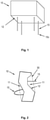
- FIG. 1 shows a molded part 10 that was produced according to the inventive method for producing a molded part in a 3D printing process.
- the molded part 10 has a surface 12 to be treated, ie to be smoothed.
- Holding means 15 are arranged on the molded part 10 or on the surface 12 of the molded part 10, which are designed here as holding pins. Alternatively or additionally, holding means configured as spacers can also be provided, as with reference to FIG 4 , 6 and 7 explained.
- the holding pins 15 are dimensioned in such a way that they can carry the molded part 10 when the molded part 10 is placed on or with the holding pins 15 on a surface.
- the retaining pins 15 are dimensioned such that the connection points at which the retaining pins 15 are arranged on the surface 12 of the molded part 10 have the smallest possible cross-sectional area.
- the retaining pins can have a cross-sectional area of less than 5 mm 2 , preferably less than 2 mm 2 , particularly preferably less than 1 mm 2 on the section facing the surface of the molded part.
- the cross-sectional areas mentioned are merely exemplary, but nevertheless advantageous cross-sectional areas.
- the dimensions of the retaining pins 15 are selected depending on the weight of the molded part, the duration of the surface treatment and/or the surface treatment agent used. For example, in the case of very light molded parts, retaining pins with very small cross-sectional areas can be provided.
- the holding means 15 are detached from the surface 12 of the molded part 10 after the etching process and, if necessary, after a drying process, so that only the very small connection points remain as untreated sections of the surface 12. These very small connection points do not have a negative effect either visually or haptically. Because the material used for the production of the molded part is already perfectly fused or glued at the connection points during production, so that the detachment of the holding means 15 from the surface 12 of the molded part 10 leaves untreated connection points, but these remain due to the fusion or adhesion of the material are smooth anyway during production. A surface treatment of the connection points is therefore not necessary.
- the holding means 15 can be cut off with a knife or a blade.
- the holding means in order to detach or remove the holding means 15 from the molded part 10, it is provided that the holding means be treated with a preferably liquid separating agent. This can be done, for example, by immersing the molded part with the holding means arranged thereon in the liquid release agent for a predetermined period of time.
- a solvent for example, can be used as a release agent.
- the release agent causes the holding means to dissolve at least partially.
- the holding means are made of a material or of a material composition which is different from the material or the material composition of the molded part.
- the material or the material composition of the molded part is selected depending on the release agent used so that it is opposite to the release agent is persistent.
- the material or the material composition of the holding means is selected in such a way that it is not resistant to the separating agent and can therefore dissolve in the separating agent.
- the release agent can also be selected in such a way that it can dissolve the holding means while the molded part is not adversely affected by the release agent.
- the same powder material can be used for the holding means as for the holding means, provided that the production takes place using an adhesive.
- an adhesive that is resistant to the release agent is used for the molding, while an adhesive that is not resistant to the release agent is used for the holding means.
- the holding pins are also designed in such a way that the molded part can be hung with them in the treatment room of an etching device without the molded part 10 touching the floor or the inner wall of the treatment room.
- receiving devices can be provided in the treatment room, which receive the ends of the retaining pins 15 facing away from the surface 12 of the molded part 10 .
- blind holes can be provided on the floor of the treatment room, into which the retaining pins can be inserted or pushed.
- retaining pins 15 are shown in 1 straight retaining pins 15 with two ends.
- curved holding pins can also be provided.
- retaining pins can also be provided which have more than two ends, for example retaining pins in the form of a T-profile which have three ends. According to the invention, it is essential that the retaining pins are attached with at least one end to the surface of the molded part.
- Another possible embodiment of a holding means or holding pin is with reference to 2 shown.
- the molded part After the molded part has been introduced into the treatment chamber, the molded part is exposed to the etchant, which can be accomplished, for example, by vaporizing the surface or by immersing the molded part in a liquid etchant.
- the etching device can be designed in such a way that the molded part 10 can be moved, for example rotated, in the treatment room during the surface treatment. The molded part is moved in the treatment room in such a way that the surface 12 of the molded part does not come into contact with the floor or with the inner wall of the treatment room.
- moving the shaped part in the treatment chamber can ensure uniform vaporization of the surface and thus uniform smoothing of the surface.
- a molded part with four holding means arranged on the surface 12 is shown.
- more or fewer than four holding means or holding pins can also be provided.
- the holding means and the molded part are designed in one piece or in one piece and are produced in one piece or in one piece in a 3D printing process.
- the holding means or the holding pins are provided on those areas of the surface 12 of the molded part 10 that represent optically less exposed areas. Such optically less exposed areas can, for example, be indentations on the surface of the molded part, as in 2 shown.
- the molded part is produced or printed together with the holding means or holding pins, the molded part can be fed to the etching process immediately after printing without any further preparatory measures. Arranging the holding means or holding pins after the molding 10 has been printed can thus be dispensed with entirely.
- the 3D printer is provided with a data set or a print file, the data set or the printed file containing instructions or information about the geometry of the molded part and the geometry of the holding means.
- the data set itself can be produced with a conventional CAD program or 3D design/modeling program that is adapted to generate a data set that can be read or interpreted by the 3D printer.
- the program can be adapted to automatically generate holding means based on the geometry of the molded part and to insert these into the data set.
- the 3D printer can be adapted to calculate suitable holding means for a data set that only contains information about the geometry of the molded part and to print them out together with the molded part.
- FIG. 2 shows a cross section of a molded part 10, which has a depression or a recess 11 or a concave surface section.
- the retaining means or a retaining pin 15 is to be arranged on the surface 12 of this recess 11, it is provided that the retaining pin is arranged relative to the surface of the molded part and is dimensioned in such a way that the end of the retaining pin facing away from the surface also ßberrenz an imaginary convex envelope 30 of the molded part.
- This arrangement is particularly advantageous when the recess or depression 11 a optically less exposed portion of the molding 10 forms.
- the projection of the retaining pin 12 on the imaginary convex envelope 30 also ensures that, for example when the molded part 10 is placed on the pins 15 in the treatment room, the surface of the molded part does not touch the floor.
- the holding means or the holding pin 15 can also be curved, with the holding means being attached at both ends to the surface of the molded part. If both ends are arranged in the recess or in the concave surface section, the holding means is to be dimensioned in such a way that it runs outside the imaginary convex envelope 30 in sections.
- FIG. 3 shows a portion of a surface 12 of a molded part with a retaining pin 15 arranged thereon in an enlarged view.
- the retaining pin tapers at the end facing the surface 12, so that the retaining pin itself has sufficient stability and the point at which the retaining pin is attached to the surface simultaneously has a minimal cross-sectional area. If several holding means or holding pins are arranged on the surface of the molded part 10, the cross-sectional area in the point of contact between the holding pin and the surface of the molded part can be reduced even further.
- it can be provided to provide a predetermined breaking point 20 between the surface of the molded part and the holding means or to form a predetermined breaking point 20 at this point during the printing of the molded part with the holding pins. This can simplify the removal of the holding means or the holding pins after the etching process.
- the configuration shown of the section of the holding means 15 facing the surface 12 of the molded part can advantageously also be used for the in 4 and 6 shown spacers 15d are provided.
- the sections of the spacers 15d facing the surfaces can accordingly also converge in a tapering manner and predetermined breaking points can also be provided if necessary.
- FIG. 4 shows an advantageous embodiment of a holding means according to the invention, which is particularly suitable for arranging several molded parts 10 in a treatment chamber of an etching device without the molded parts touching the floor or the inner wall of the treatment chamber and without the molded parts touching each other. If several moldings are to be etched at the same time, care shall also be taken to ensure that the moldings do not touch each other, to avoid leaving untreated surface areas at the points of contact between the moldings and to avoid merging touching moldings at the point of contact . Fusing can occur because the surface can be softened by the etchant used.
- the embodiment shown has the holding means on a lattice box 15a with holding pins 15b arranged thereon.
- the molded parts 10 are arranged inside the lattice box 15a in such a way that the molded parts 10 are located completely within the boundary surfaces of the lattice box 15a.
- the molded parts 10 are held in a predetermined position within the lattice box by means of the retaining pins 15b which are arranged on the lattice box 15a and extend into the interior of the lattice box.
- spacers 15d are arranged between two molded parts 10 and are connected on both sides to a molded part in each case.
- a spacer 15d can also be designed in such a way that more than two molded parts 10 are held at a distance from one another within the lattice box.
- Such a spacer 15d designed as a T-profile is in 6 shown.
- a molded part 10 is attached to each of the three ends of the T-profile spacer.
- the number of retaining pins 15b to be provided and the number of spacers 15d to be provided depend on the number of molded parts arranged in the lattice box and on the geometry of the individual molded parts, it being possible for several molded parts to be arranged in the lattice box, each of which has a different geometry.
- the lattice bars can also be dispensed with if the retaining pins 15b are fastened to the edges of the lattice box, as in figure 5 shown.
- the provision of a lattice box with retaining pins arranged thereon and the use of spacers between the mold parts and the arrangement of the mold parts within the lattice box, as with reference to FIG 4 explained, has the advantage that the molded parts 10 can be placed in any orientation in the treatment chamber of the etching device, while at the same time ensuring that the molded parts touch neither the bottom nor the side wall.
- the entire lattice box with the molded parts arranged therein can be moved, for example using a stirrer, without the molded parts touching the bottom or the side wall or the stirrer.
- the lattice box also ensures that during the etching process, regardless of the etching process used, the entire surface of the molded parts is largely evenly coated with the etchant. It is advantageous here if only as many lattice bars are provided as are necessary for fastening the retaining pins 15b to the lattice box.
- the lattice boxes 15a shown, the retaining pins 15b, the spacers 15d and the molded parts 10 arranged in the lattice box are produced according to the invention in one piece or in one piece, ie produced or printed out in a single printing process with a 3D printer.
- connection points between the retaining pins 15b and the mold parts 10 or between the spacers 15d and the mold parts 10 can be configured as with reference to FIG 3 shown.
- the spacers 15d can be detached from the molded parts by means of cutting.
- the spacers 15d can be made of a material that is different from the material of the molded body, so that the spacers can be detached from the molded body with the aid of a release agent, as with reference to FIG 1 explained.
- the above with reference to 1 The data set described or the print file that is made available to a 3D printer can also have instructions or information about the geometry of the spacers 15d.
- the CAD program or 3D design/modeling program can be adapted to automatically generate spacers based on the geometry of the molded parts arranged in the lattice box, with which the molded parts are connected to one another at a distance from one another, and to insert these into the data set.
- the 3D printer itself can be adapted to calculate suitable spacers for a data set that only contains information about the geometry of the molded part and to print them out together with the molded parts.
- lattice boxes 15a which have the shape of a cuboid. According to the invention, however, all geometric shapes are suitable as lattice boxes, in particular also spherical or cylindrical lattice boxes. In a special embodiment, lattice boxes can also be provided, which essentially describe a convex, preferably minimally convex shell, in which a plurality of molded parts spaced apart from one another are enclosed.
- FIG. 6 shows an embodiment according to the invention, in which a plurality of molded parts 10 are arranged at a distance from one another and are connected to one another by means of spacers 15d.
- a spacer is designed here as a straight spacer, with which the two vertical molded parts are connected to each other.
- the other spacer is designed as a T-shaped spacer.
- the T-shaped spacer has three ends, each connected to one of the three molded parts.
- Two holding means or holding pins 15b are also arranged on the left of the two vertical shaped bodies, with the purpose of arranging the composite formed from shaped body 10 and spacer 15d in an etching device such that the shaped bodies touch neither the bottom nor the side walls during the etching process.
- the combination of shaped body 10 and spacer 15d can be placed with the retaining pins 15b on the bottom of the etching device.
- the plurality of mold parts can be arranged in the etching device at a distance from one another in such a way that they do not touch the walls of the etching device.
- spacers are shown having two or three ends to which moldings can be attached.
- spacers can be provided which have n ends in order to connect n molded parts to one another.
- FIG 7 An example of a spacer 15d having a plurality of ends is shown in FIG 7 shown.
- the spacer 15d is designed essentially in the form of a double rake.
- a shaped body 10 is arranged at each end of the spacer 15d.
- different shaped bodies can be connected at a distance from each other with a spacer 15d.
- the method according to the invention for treating a surface of a molded part produced in a 3D printing process advantageously makes it possible to feed the printed molded part directly to an etching process, without having to carry out preparatory measures on the molded part itself or measures in the treatment room of the etching device that would prevent the molded part from being touched prevent the floor or the inner wall of the treatment room.
- the time required for smoothing the surface of the molded part can thus be significantly reduced.
- the method according to the invention is particularly suitable for treating the surface of a molded part for the industrial production of molded parts.
Landscapes
- Engineering & Computer Science (AREA)
- Manufacturing & Machinery (AREA)
- Chemical & Material Sciences (AREA)
- Materials Engineering (AREA)
- Physics & Mathematics (AREA)
- Optics & Photonics (AREA)
- Mechanical Engineering (AREA)
- Human Computer Interaction (AREA)
- General Physics & Mathematics (AREA)
- Automation & Control Theory (AREA)
Description
- Die Erfindung betrifft ein Verfahren zum Herstellen und zur Oberflächenbehandlung eines Formteils, welches in einem 3D-Druckverfahren, insbesondere in einem pulverbasierten Fertigungs- bzw. Druckverfahren hergestellt wird.
- Es ist bekannt, Formteile in einem 3D-Druckverfahren herzustellen. Unter 3D-Druckverfahren werden rein additive Fertigungsverfahren verstanden. Die Oberflächen von in einem 3D-Druckverfahren hergestellten Formteilen werden im Stand der Technik vorzugsweise manuell behandelt bzw. bearbeitet, um eine glatte Oberfläche zu erreichen. Denn im 3D-Druckverfahren hergestellte Formteile, insbesondere wenn Pulver basierte Druckverfahren verwendet werden, weisen in der Regel eine fertigungsbedingte raue Oberfläche auf, was in vielen Fällen den haptischen Eindruck beim Benutzer des Formteils negativ beeinflusst.
- Um die Oberflächenbehandlung, insbesondere das Glätten der Oberfläche des Formteils effizienter zu gestalten, ist es bekannt, die zu bearbeitenden Formteile in ein Gefäß zu geben, in das auch ein Ätzmittel gegeben wird. Durch das in Kontakt bringen der Oberfläche des Formteils mit dem Ätzmittel wird ein Glätten der Oberfläche erreicht. Bei diesem Verfahren können auch mehrere zu behandelnde Formteile in das Gefäß gegeben werden.
- Das aus dem Stand der Technik bekannte Ätzverfahren hat allerdings den Nachteil, dass die zu behandelnden Formteile zumindest teilweise auf dem Boden des Gefäßes aufliegen oder zumindest teilweise an der Seitenwand des Gefäßes anliegen bzw. dass sich mehrere zu behandelnde Formteile berühren.
- An den Stellen, wo die Formteile auf dem Boden oder an der Seitenwand anliegen bzw. wo sich die Formteile berühren, gelangt kein oder nur unzureichend Ätzmittel an die Oberfläche des Formteils, was dazu führt, dass ein oder mehrere Abschnitte der Oberfläche des Formteils nicht oder nur unzureichend geglättet werden. Die Oberfläche der behandelten Formteile weisen daher nach dem Ätzvorgang nach wie vor raue Abschnitte auf, die sich sowohl optisch als auch haptisch von den geglätteten Abschnitten deutlich unterscheiden. Dies macht ein manuelles Nachbearbeiten der Oberfläche der Formteile notwendig.
- Ein weiterer Nachteil liegt darin, dass die Oberfläche der Formteile während des Ätzvorganges weich wird bzw. aufgeweicht wird. Dies kann dazu führen, dass die Formteile an den Stellen, wo sie den Boden und/oder die Seitenwand des Gefäßes berühren, abgeflacht werden oder gar ihre Form verändern, was nicht wünschenswert ist.
Fig. 8 zeigt ein Formteil vor 41 und nach 42 einem Ätzvorgang, der gemäß einem aus dem Stand der Technik bekannten Verfahren durchgeführt wird, indem das Formteil auf dem Boden 40 eines Behälters aufliegen. Erkennbar ist hier, dass die Unterseite des Formteils 42 nach dem Ätzvorgang abgeflacht ist. Die abgeflachten Stellen müssen in der Regel manuell nachbearbeitet werden. Ferner können sich berührende Formteile miteinander verkleben und müssen nach dem Ätzvorgang meist manuell getrennt und ebenfalls nachbearbeitet werden. - Für eine Serienfertigung ist ein solches manuelles Nachbearbeiten der Formteile allerdings nicht geeignet. Zudem kann bei dem manuellen Nachbearbeiten der noch vorhandenen rauen und gegebenenfalls abgeflachten Oberflächenabschnitte nicht gewährleistet werden, dass die gesamte Oberfläche einheitlich glatt ausgestaltet ist bzw. eine einheitliche Oberflächenstruktur aufweist.
- Aus der Druckschrift
US 2012/0018115 A1 ist ein Verfahren zur Herstellung eines Bauteils bekannt, bei welchem Verfahren das Bauteil auf einer Plattform durch sukzessives Aufschmelzen von Metallpulver-Schichten unter Ausbildung einer übereinander liegenden Schichtenfolge gebildet wird. Das Verfahren wird dadurch erheblich vereinfacht und flexibler gestaltet, dass zur leichteren Trennung des fertigen Bauteils von der Plattform zwischen dem Bauteil und der Plattform eine Trennschicht vorgesehen wird, welche eine Trennung des fertigen Bauteils von der Plattform ohne Beschädigung des fertigen Bauteils ermöglicht. - Aufgabe der vorliegenden Erfindung ist es daher, Lösungen bereitzustellen, die es erlauben, Oberflächen von Formteilen, insbesondere von in einem 3D-Druckverfahren hergestellten Formteilen effizienter zu behandeln, insbesondere effizienter zu glätten, wobei die Lösungen auch eine effiziente Serienfertigung ermöglichen sollen.
- Diese Aufgabe wird erfindungsgemäß durch ein Verfahren zum Behandeln einer Oberfläche zumindest eines in einem 3D-Druckverfahren, insbesondere von in einem pulverbasierten Fertigungs- bzw. Druckverfahren hergestellten Formteils mit einem Ätzmittel, nach Anspruch 1 gelöst. Vorteilhafte Ausgestaltungen und Weiterbildungen der Erfindung ergeben sich aus den jeweiligen abhängigen Ansprüchen. Unter 3D-Druckverfahren werden rein additive Fertigungsverfahren verstanden.
- Bereitgestellt wird demnach ein Verfahren zum Behandeln einer Oberfläche zumindest eines in einem 3D-Druckverfahren (additives Fertigungsverfahren), insbesondere von in einem pulverbasierten Fertigungs- bzw. Druckverfahren hergestellten Formteils mit einem Oberflächenbehandlungsmittel, wobei
- an der Oberfläche des Formteils zumindest ein von der Oberfläche abstehendes Haltemittel angeordnet wird,
- das Formteil mit dem zumindest einen Haltemittel derart in einen Behandlungsraum, der eine durch einen Boden und Seitenwandungen gebildete Innenwandung aufweist, einer Behandlungsvorrichtung eingebracht wird, dass die Oberfläche des Formteils nicht in Berührung mit der Innenwandung kommt,
- die Oberfläche des Formteils nach Einbringen in den Behandlungsraum für einen vorbestimmten Zeitraum mit dem Oberflächenbehandlungsmittel beaufschlagt wird, und
- nach dem Beaufschlagen der Oberfläche des Formteils mit dem Oberflächenbehandlungsmittel das Formteil aus dem Behandlungsraum entnommen wird und die Haltemittel von der Oberfläche des Formteils abgelöst werden.
- Das Beaufschlagen der Oberfläche des Formteils mit dem Oberflächenbehandlungsmittel kann ein Bedampfen der Oberfläche mit dem Oberflächenbehandlungsmittel, ein Besprühen der Oberfläche mit dem Oberflächenbehandlungsmittel, ein Eintauchen des Formteils in ein flüssiges Oberflächenbehandlungsmittel, und Kombinationen hiervon umfassen.
- Während der Beaufschlagung mit dem Oberflächenbehandlungsmittel kann das Formteil in dem Behandlungsraum relativ zu dem Behandlungsraum bewegt, insbesondere gedreht werden.
- Nach dem Beaufschlagen der Oberfläche des Formteils mit dem Oberflächenbehandlungsmittel kann das Formteil einer Reinigung unterzogen werden, um an der Oberfläche des Formteils vorhandenes überschüssiges Oberflächenbehandlungsmittel zu entfernen, etwa indem an der Oberfläche vorhandene Säure mit einer Lauge neutralisiert wird, wobei das Formteil zum Reinigen erhitzt wird, um das überschüssige Oberflächenbehandlungsmittel von der Oberfläche des Formteils zu lösen und/oder wobei das Formteil vor und/oder während der Beaufschlagung der Oberfläche mit dem Oberflächenbehandlungsmittel erwärmt wird, um die Behandlungsdauer der Oberflächenbehandlung zu reduzieren.
- Das Haltemittel umfasst zumindest einen mindestens zwei Enden aufweisenden Haltestift, wobei zumindest ein Ende des Haltestiftes an der Oberfläche des Formteils befestigt ist.
- Das Haltemittel kann eine Gitterbox umfassen, wobei das Formteil innerhalb der Gitterbox angeordnet wird, derart, dass zumindest ein Ende des Haltestiftes an der Oberfläche des Formteils und zumindest ein anderes Ende des Haltestiftes an der Wandung der Gitterbox befestigt ist, wobei die Oberfläche des Formteils die Gitterbox nicht berührt.
- Das Haltemittel kann zumindest einen mindestens zwei Enden aufweisenden Abstandshalter umfassen, wobei mehrere Formteile beabstandet zueinander und sich nicht berührend angeordnet werden, wobei die mehreren Formteile über den zumindest einen Abstandshalter miteinander verbunden werden.
- Die mehreren Formteile können innerhalb der Gitterbox angeordnet sein.
- Das Haltemittel und das Formteil können einteilig ausgestaltet sein und/oder in dem 3D-Druckverfahren einteilig hergestellt werden.
- Vorteilhaft ist es, wenn der Haltestift des Haltemittels so relativ zur Oberfläche des Formteils angeordnet wird, dass der Haltestift zumindest abschnittsweise außerhalb einer gedachten konvexen Hülle des Formteils liegt.
- Zwischen der Oberfläche des Formteils und dem Haltemittel kann eine Sollbruchstelle ausgebildet werden, an der das Haltemittel nach dem Beaufschlagen der Oberfläche des Formteils mit dem Ätzmittel von dem Formteil lösbar ist.
- Eine minimale Querschnittsfläche des Haltemittels an dem der Oberfläche des Formteils zugewandten Abschnitt kann in Abhängigkeit vom Gewicht des Formteils, von der Oberflächenbehandlungsdauer, von dem verwendeten Oberflächenbehandlungsmittel, von dem Fertigungsverfahren, von dem verwendeten Material und/oder Kombinationen hiervon gewählt werden.
- Vorteilhaft ist es, wenn
- das zumindest eine Formteil ein erstes Material oder eine erste Materialzusammensetzung und das zumindest eine Haltemittel ein zweites Material oder eine zweite Materialzusammensetzung aufweisen,
- zum Ablösen der Haltemittel von der Oberfläche des Formteils zumindest die Haltemittel mit einem vorzugsweisen flüssigen Trennmittel beaufschlagt werden,
- Es hat sich als vorteilhaft erwiesen, wenn das Formteil in einem pulverbasierten Fertigungs- bzw. Druckverfahren hergestellt wird, das erste Material oder die erste Materialzusammensetzung ein erstes Klebemittel und das zweite Material oder die zweite Materialzusammensetzung ein zweites Klebemittel aufweisen, wobei das erste Klebemittel gegenüber dem Trennmittel beständig ist und das zweite Klebemittel gegenüber dem Trennmittel nicht beständig ist.
- Bereitgestellt wird des Weiteren ein Verfahren zum Herstellen eines Formteils in einem 3D-Druckverfahren, insbesondere in einem pulverbasierten Fertigungs- bzw. Druckverfahren, welches nach der Herstellung einer Oberflächenbehandlung mit einem Oberflächenbehandlungsmittel zu unterziehen ist, wobei das Formteil zusammen mit zumindest einem von der Oberfläche des Formteils abstehenden Haltemittel hergestellt wird, wobei das Formteil und das zumindest eine Haltemittel einteilig ausgestaltet ist.
- Das Haltemittel kann zumindest teilweise über eine gedachte konvexe Hülle des Formteils überstehen.
- Das Haltemittel kann als Abstandshalter hergestellt werden, wobei ein Abstandshalter zumindest zwei Formteile beabstandet zueinander miteinander verbindet, wobei der Abstandshalter ebenfalls in dem 3D-Druckverfahren hergestellt wird, sodass der Abstandshalter und die Formteile einteilig ausgestaltet sind.
- Das Haltemittel kann als Gitterbox mit zumindest einem Haltestift hergestellt werden, wobei das Formteil innerhalb der Gitterbox hergestellt wird und wobei das Formteil mit dem zumindest einen Haltestift an der Gitterbox befestigt ist, wobei der zumindest eine Haltestift ebenfalls in dem 3D-Druckverfahren hergestellt wird, sodass die Gitterbox, der zumindest eine Haltestift und das Formteil einteilig ausgestaltet sind.
- Zur Herstellung des Formteils kann ein erstes Material oder eine erste Materialzusammensetzung und zum Herstellen des Haltemittels ein zweites Material oder eine zweite Materialzusammensetzung verwendet werden, wobei das erste Material oder die erste Materialzusammensetzung und das zweite Material oder die zweite Materialzusammensetzung so gewählt werden, dass mit einem vorzugsweise flüssigen Trennmittel die Haltemittel innerhalb einer vorbestimmten Zeit vollständig auflösbar sind, ohne dabei das Formteil oder die Oberfläche des Formteils zu verändern, insbesondere zu beschädigen.
- Das Oberflächenbehandlungsmittel umfasst ein Ätzmittel und/oder ein Lösungsmittel.
- Bereitgestellt wird des weiteren ein Datensatz zum Steuern eines 3D-Druckers zur Herstellung eines dreidimensionalen Formteils, welches nach der Herstellung einer Oberflächenbehandlung mit einem Oberflächenbehandlungsmittel zu unterziehen ist, wobei der Datensatz von dem 3D-Drucker interpretierbare erste und zweite Anweisungen aufweist, gemäß denen der 3D-Drucker das Formteil herstellt, wobei
- die ersten Anweisungen Informationen über die Geometrie des herzustellenden Formteils umfassen, und
- die zweiten Anweisungen Informationen über die Geometrie von zumindest einem herzustellenden Haltemittel umfassen,
- Die zweiten Anweisungen können weiter so gewählt ein, dass
- das Haltemittel als zumindest teilweise über eine gedachte konvexe Hülle des Formteils überstehendes Haltemittel hergestellt wird, und/oder
- das Haltemittel als eine das Formteil umgebende Gitterbox hergestellt wird, wobei das Formteil mit von dem 3D-Drucker hergestellten Haltestiften an der Gitterbox befestigt ist, und/oder
- Abstandshalter hergestellt werden, die zumindest zwei zueinander beabstandete und sich nicht berührende Formteile miteinander verbinden, wobei die Formteile und die Abstandshalter einteilig hergestellt werden.
- Bereitgestellt wird ferner ein Computerprogrammprodukt, insbesondere Computeranwendung, das in den Speicher eines Computers geladen werden kann und auf dem Computer zur Ausführung gebracht werden kann, zur Herstellung eines von einem 3D-Drucker interpretierbaren Datensatzes zum Herstellen zumindest eines dreidimensionalen Formteils, wobei das Computerprogrammprodukt Programmabschnitte umfasst, die angepasst sind,
- basierend auf den Geometriedaten des zumindest einen Formteils eine Anzahl von Haltemitteln zu ermitteln, die von der Oberfläche des Formteils abstehen und/oder zumindest zwei zueinander beabstandete und sich nicht berührende Formteile miteinander verbinden, wobei die Haltemittel und das zumindest eine Formteil einteilig ausgestaltet sind,
- für jedes ermittelte Haltemittel einen Querschnitt und/oder eine Länge und/oder eine Position an der Oberfläche des Formteils und/oder eine Form zu ermitteln, und
- für die so ermittelten Haltemittel von dem 3D-Drucker interpretierbare Anweisungen zu erzeugen und in den Datensatz einzufügen.
- Weitere Einzelheiten und Merkmale der Erfindung ergeben sich aus der nachfolgenden Beschreibung in Verbindung mit der Zeichnung. Es zeigt:
- Fig. 1
- ein erfindungsgemäßes in einem 3D-Druckverfahren hergestelltes Formteil;
- Fig. 2
- einen Querschnitt eines Formteils mit einer gedachten konvexen Hülle;
- Fig. 3
- ein an der Oberfläche eines Formteils angeordnetes Haltemittel (Haltestift) in einer vergrößerten Ansicht;
- Fig. 4
- zwei in einer als Gitterbox ausgestaltete Haltemittel angeordnete Formteile;
- Fig. 5
- eine alternative Ausgestaltung der in
Fig. 4 gezeigten Gitterbox; - Fig. 6
- zwei Formteile, die erfindungsgemäß mit Abstandshalter miteinander verbunden sind;
- Fig. 7
- eine Anzahl von Formteilen, die erfindungsgemäß einem Abstandshalter miteinander verbunden sind; und
- Fig. 8
- ein Formteil, dessen Oberfläche gemäß einem aus dem Stand der Technik bekannten Verfahren behandelt wird (vor und nach der Oberflächenbehandlung).
- Detaillierte Beschreibung der Erfindung
- Erfindungsgemäß werden die zu bearbeitenden Formteile in einem generativen Fertigungsverfahren bzw. in einem additivem Fertigungsverfahren (3D-Druckverfahren) hergestellt. Die Oberfläche des hergestellten Formteils weist fertigungsbedingte Unebenheiten auf, die ein Anhaften von Schmutz bzw. Verunreinigungen an der Oberfläche des Formteils begünstigen. Bei Pulver basierten 3D-Druckverfahren kann zudem ein das Formteil umgebendes Pulver an der Oberfläche des Formteils haften bleiben oder mit der Oberfläche verschmolzen sein, was ebenfalls zu einer rauen Oberfläche führt. Die raue bzw. poröse Oberfläche des Formteils wirkt sich zudem negativ auf die Haptik des Formteils aus.
- Erfindungsgemäß ist es daher vorgesehen, die Oberfläche eines in einem 3D-Druckverfahren hergestellten Formteils zu glätten, insbesondere unter Verwendung eines Oberflächenbehandlungsmittels, etwa ein Ätzmittel oder ein geeignetes Lösungsmittel. Das zu verwendende Oberflächenbehandlungsmittel hängt im Wesentlichen von dem Material bzw. von den Materialien ab, mit dem bzw. denen das Formteil hergestellt wurde.
-
Fig. 1 zeigt ein Formteil 10, das gemäß dem erfindungsgemäßen Verfahren zum Herstellen eines Formteils in einem 3D-Druckverfahren hergestellt wurde. - Das Formteil 10 weist eine zu behandelnde, d.h. zu glättende Oberfläche 12 auf.
- An dem Formteil 10 bzw. an der Oberfläche 12 des Formteils 10 sind Haltemittel 15 angeordnet, die hier als Haltestifte ausgestaltet sind. Alternativ oder zusätzlich können auch als Abstandshalter ausgestaltete Haltemittel vorgesehen sein, wie mit Bezug auf
Fig. 4 ,Fig. 6 undFig. 7 erläutert. - Die Haltestifte 15 sind so dimensioniert, dass diese das Formteil 10 tragen können, wenn das Formteil 10 mit bzw. auf den Haltestiften 15 auf einer Oberfläche abgestellt wird. So ist es beispielsweise möglich, das Formteil 10 in einen Behandlungsraum einer Ätzvorrichtung abzustellen, sodass lediglich die von der Oberfläche 12 des Formteils 10 abgewandten Enden 15c der Haltestifte 15 einen Boden des Behandlungsraumes berühren. Dadurch wird vermieden, dass das Formteil 10 bzw. die Oberfläche 12 des Formteils auf dem Boden des Behandlungsraumes der Ätzvorrichtung aufliegt, wodurch vermieden wird, dass die Oberfläche 12 des Formteils 10 nach dem Ätzvorgang Bereiche bzw. Abschnitte aufweist, die gar nicht oder nur unzureichend geglättet wurden. Zudem wird dadurch vermieden, dass sich die Geometrie des Formteils ändert, etwa abgeflachte Bereiche entstehen, wenn die Oberfläche des Formteils während des Ätzvorganges weich bzw. aufgeweicht wird.
- Zudem sind die Haltestifte 15 so dimensioniert, dass die Verbindungsstellen, an denen die Haltestifte 15 an der Oberfläche 12 des Formteils 10 angeordnet sind, eine möglichst geringe Querschnittsfläche aufweisen. Beispielsweise können die Haltestifte an dem der Oberfläche des Formteils zugewandten Abschnitt eine Querschnittsfläche aufweisen, die kleiner als 5 mm2, vorzugsweise kleiner als 2 mm2, besonders bevorzugt kleiner als 1 mm2 ist. Die genannten Querschnittsflächen sind lediglich beispielhafte, aber dennoch vorteilhafte Querschnittsflächen. Erfindungsgemäß werden die Dimensionen der Haltestifte 15 in Abhängigkeit vom Gewicht des Formteils, von der Oberflächenbehandlungsdauer und/oder von dem verwendeten Oberflächenbehandlungsmittel gewählt. So können beispielsweise bei sehr leichten Formteilen Haltestifte mit sehr geringen Querschnittsflächen vorgesehen werden.
- Die Haltemittel 15 werden nach dem Ätzvorgang und gegebenenfalls nach einem Trocknungsvorgang von der Oberfläche 12 des Formteils 10 abgelöst, sodass lediglich die sehr kleinen Verbindungsstellen als unbehandelte Abschnitte der Oberfläche 12 zurückbleiben. Diese sehr kleinen Verbindungsstellen wirken sich weder optisch noch haptisch nachteilig aus. Denn das für die Herstellung des Formteils verwendete Material ist an den Verbindungstellen ohnehin während der Herstellung perfekt verschmolzen bzw. verklebt, sodass durch das Ablösen der Haltemittel 15 von der Oberfläche 12 des Formteils 10 zwar unbehandelte Verbindungsstellen zurückbleiben, diese aber aufgrund des Verschmelzens bzw. Verklebens des Materials während der Herstellung ohnehin glatt sind. Eine Oberflächenbehandlung der Verbindungsstellen ist daher nicht notwendig.
- Beispielsweise können die Haltemittel 15, etwa mit einem Messer oder einer Klinge abgeschnitten werden.
- In einer vorteilhaften Ausgestaltung der Erfindung ist es vorgesehen, zum Ablösen bzw. Entfernen der Haltemittel 15 von dem Formteil 10 die Haltemittel mit einem vorzugsweise flüssigen Trennmittel zu bearbeiten. Dies kann beispielweise erfolgen, indem das Formteil mit den daran angeordneten Haltemittel für einen vorbestimmten Zeitraum in das flüssige Trennmittel eingetaucht wird. Als Trennmittel kann beispielsweise ein Lösungsmittel verwendet werden.
- Das Trennmittel bewirkt, dass sich die Haltemittel zumindest teilweise auflösen. Um ein Auflösen der Haltemittel in dem Trennmittel zu gewährleisten, ohne dass das Formteil und/oder dessen Oberfläche beeinträchtigt werden, ist es erfindungsgemäß vorteilhaft, wenn die Haltemittel aus einem Material oder aus einer Materialzusammensetzung hergestellt werden, das bzw. die verschieden von dem Material oder der Materialzusammensetzung des Formteils ist.
- Das Material bzw. die Materialzusammensetzung des Formteils wird in Abhängigkeit des verwendeten Trennmittels so gewählt, dass es gegenüber dem Trennmittel beständig ist. Das Material bzw. die Materialzusammensetzung der Haltemittel hingegen wird so gewählt, dass es gegenüber dem Trennmittel nicht beständig ist und sich somit in dem Trennmittel auflösen kann. Umgekehrt kann auch das Trennmittel in Abhängigkeit von den verwendeten Materialien so gewählt werden, dass es die Haltemittel auflösen kann, während das Formteil von dem Trennmittel nicht beeinträchtigt wird.
- Wenn das Formteil und die daran angeordneten Haltemittel in einem pulverbasierten 3D-Druckverfahren hergestellt werden, kann für die Haltemittel das gleiche Pulvermaterial verwendet werden wie für die Haltemittel, sofern die Herstellung unter Verwendung eines Klebemittels erfolgt. Um ein Auflösen der Haltemittel in dem Trennmittel zu gewährleisten, ohne dass das Formteil beeinträchtigt wird, ist es vorgesehen, für die Haltemittel ein anderes Klebemittel zu verwenden als für das Formteil. Vorzugsweise wird für das Formteil ein Klebemittel verwendet, das gegenüber dem Trennmittel beständig ist, während für die Haltemittel ein Klebemittel verwendet wird, das gegenüber dem Trennmittel nicht beständig ist.
- Erfindungsgemäß sind die Haltestifte auch so ausgestaltet, dass das Formteil mit Ihnen in den Behandlungsraum einer Ätzvorrichtung gehängt werden kann, ohne dass das Formteil 10 den Boden bzw. die Innenwandung des Behandlungsraumes berührt. In einer weiteren alternativen Ausgestaltung können in dem Behandlungsraum Aufnahmevorrichtung vorgesehen sein, die die von der Oberfläche 12 des Formteils 10 abgewandten Enden der Haltestifte 15 aufnehmen. Beispielsweise können an dem Boden des Behandlungsraumes Sackbohrungen vorgesehen sein, in die die Haltestifte eingesteckt bzw. eingeschoben werden können.
- Gezeigt sind in
Fig. 1 gerade Haltestifte 15 mit zwei Enden. Alternativ hierzu können auch gekrümmte Haltestifte vorgesehen werden. Ferner können auch Haltestifte vorgesehen werden, die mehr als zwei Enden aufweisen, etwa Haltestifte in Form eines T-Profils, die drei Enden aufweisen. Erfindungsgemäß wesentlich ist, dass die Haltestifte mit zumindest einem Ende an der Oberfläche des Formteils befestigt werden. Eine weitere mögliche Ausgestaltung eines Haltemittels bzw. Haltestiftes ist mit Bezug aufFig. 2 gezeigt. - Nachdem das Formteil in den Behandlungsraum eingebracht wurde, wird das Formteil mit dem Ätzmittel beaufschlagt, was beispielsweise mittels Bedampfen der Oberfläche oder mittels Eintauchen des Formteils in ein flüssiges Ätzmittel bewerkstelligt werden kann. Zudem kann die Ätzvorrichtung so ausgestaltet sein, dass das Formteil 10 während der Oberflächenbehandlung in dem Behandlungsraum bewegt, beispielsweise gedreht, werden kann. Das Bewegen des Formteils in dem Behandlungsraum erfolgt hierbei so, dass die Oberfläche 12 des Formteils nicht in Berührung mit dem Boden bzw. mit der Innenwandung des Behandlungsraumes kommt. Insbesondere beim Bedampfen der Oberfläche mit dem Ätzmittel kann durch das Bewegen des Formteils in dem Behandlungsraum ein gleichmäßiges Bedampfen der Oberfläche und damit ein gleichmäßiges Glätten der Oberfläche gewährleistet werden.
- In
Fig. 1 ist ein Formteil mit vier an der Oberfläche 12 angeordneten Haltemitteln gezeigt. Je nach Geometrie des Formteils 10 können auch mehr oder weniger als vier Haltemittel bzw. Haltestifte vorgesehen sein. - Erfindungsgemäß ist es vorgesehen, dass die Haltemittel und das Formteil einteilig bzw. einstückig ausgestaltet sind und einteilig bzw. einstückig in einem 3D-Druckverfahren hergestellt werden. Das bedeutet, dass das Formteil zusammen mit den daran angeordneten Haltemitteln hergestellt bzw. gedruckt wird. Vorteilhaft kann es hierbei sein, wenn die Haltemittel bzw. die Haltestifte an solchen Bereichen der Oberfläche 12 des Formteils 10 vorgesehen werden, die optisch weniger exponierte Bereiche darstellen. Solche optisch weniger exponierte Bereiche können beispielsweise Vertiefungen an der Oberfläche des Formteils sein, wie in
Fig. 2 gezeigt. - Weil das Formteil zusammen mit den Haltemitteln bzw. Haltestiften hergestellt bzw. gedruckt wird, kann das Formteil unmittelbar nach dem Drucken ohne weitere Vorbereitungsmaßnahmen dem Ätzvorgang zugeführt werden. Ein Anordnen der Haltemittel bzw. Haltestifte nach dem Drucken des Formteils 10 kann so gänzlich entfallen.
- Zum Drucken bzw. Herstellen des Formteils mit den daran angeordneten Haltemittel bzw. Haltestiften ist es vorgesehen, dem 3D-Drucker einen Datensatz bzw. eine Druckdatei zur Verfügung zu stellen, wobei der Datensatz bzw. die Druckdatei Anweisungen bzw. Informationen über die Geometrie des Formteils und über die Geometrie der Haltemittel aufweist. Der Datensatz selbst kann mit einem herkömmlichen CAD-Programm oder 3D-Design/Modelling Programm hergestellt werden, das angepasst ist, einen für den 3D-Drucker lesbaren bzw. interpretierbaren Datensatz zu erzeugen. In einer Ausgestaltung kann das Programm angepasst sein, basierend auf der Geometrie des Formteils automatisch Haltemittel zu erzeugen und diese in den Datensatz einzufügen. In einer weiteren alternativen Ausgestaltung kann der 3D-Drucker angepasst sein, für einen Datensatz, der nur Informationen über die Geometrie des Formteils enthält, geeignete Haltemittel zu berechnen und diese zusammen mit dem Formteil auszudrucken. Diese Ausgestaltungen haben den Vorteil, dass sich der Entwickler bzw. Designer eines Formteils keine Gedanken darüber machen muss, wo und wie viele Haltemittel an dem Formteil angeordnet werden müssen.
-
Fig. 2 zeigt einen Querschnitt eines Formteils 10, welches eine Vertiefung bzw. eine Aussparung 11 oder einen konkav verlaufenden Oberflächenabschnitt aufweist. Sofern das Haltemittel bzw. ein Haltestift 15 an der Oberfläche 12 dieser Aussparung 11 angeordnet werden soll, ist es vorgesehen, dass der Haltestift so relativ zur Oberfläche des Formteils angeordnet wird und so dimensioniert ist, dass das von der Oberfläche abgewandte Ende des Haltestiftes au-ßerhalb einer gedachten konvexen Hülle 30 des Formteils liegt. Diese Anordnung ist insbesondere dann vorteilhaft, wenn die Aussparung bzw. Vertiefung 11 einen optisch weniger exponierten Abschnitt des Formteils 10 bildet. Durch das Überstehen des Haltestiftes 12 an der gedachten konvexen Hülle 30 ist zudem gewährleistet, dass beispielsweise beim Abstellen des Formteils 10 in dem Behandlungsraum auf den Stiften 15 die Oberfläche des Formteils den Boden nicht berührt. - In einer weiteren Ausgestaltung kann das Haltemittel bzw. der Haltestift 15 auch gekrümmt sein, wobei das Haltemittel mit beiden Enden an der Oberfläche des Formteils befestigt ist. Sind beide Enden in der Aussparung bzw. in dem konkav verlaufenden Oberflächenabschnitt angeordnet, so ist das Haltemittel so zu dimensionieren, dass dieses abschnittsweise außerhalb der gedachten konvexen Hülle 30 verläuft.
-
Fig. 3 zeigt einen Abschnitt einer Oberfläche 12 eines Formteils mit einem daran angeordneten Haltestift 15 in einer vergrößerten Ansicht. - Erfindungsgemäß kann es vorteilhaft sein, wenn der Haltestift an dem der Oberfläche 12 zugewandten Ende verjüngend zusammenläuft, sodass der Haltestift an sich eine ausreichende Stabilität aufweist und die Stelle, an der der Haltestift an der Oberfläche befestigt ist, gleichzeitig eine minimale Querschnittsfläche aufweist. Werden mehrere Haltemittel bzw. Haltestifte an der Oberfläche des Formteils 10 angeordnet, kann die Querschnittsfläche in dem Berührungspunkt zwischen dem Haltestift und der Oberfläche des Formteils noch weiter reduziert werden.
- In einer Ausgestaltung der Erfindung kann es vorgesehen sein, zwischen der Oberfläche des Formteils und dem Haltemittel eine Sollbruchstelle 20 vorzusehen bzw. während des Druckens des Formteils mit den Haltestiften an dieser Stelle eine Sollbruchstelle 20 auszubilden. Dadurch kann das Entfernen der Haltemittel bzw. der Haltestifte nach dem Ätzvorgang vereinfacht werden.
- Die in
Fig. 3 gezeigte Ausgestaltung des der Oberfläche 12 des Formteils zugwandten Abschnittes des Haltemittels 15 kann vorteilhaft auch für die inFig. 4 undFig. 6 gezeigten Abstandshalter 15d vorgesehen werden. Die den Oberflächen zugwandten Abschnitte der Abstandshalter 15d können demnach ebenfalls verjüngend zusammenlaufen und es können gegebenenfalls ebenfalls Sollbruchstellen vorgesehen sein. -
Fig. 4 zeigt eine vorteilhafte Ausgestaltung eines erfindungsgemäßen Haltemittels, welches insbesondere dazu geeignet ist, mehrere Formteile 10 in einem Behandlungsraum einer Ätzvorrichtung anzuordnen, ohne dass die Formteile den Boden bzw. die Innenwandung des Behandlungsraumes berühren und ohne dass sich die Formteile gegenseitig berühren. Werden mehrere Formteile gleichzeitig einem Ätzvorgang unterzogen, muss auch gewährleistet werden, dass sich die Formteile nicht gegenseitig berühren, um zu verhindern, dass an den Berührungspunkten zwischen den Formteilen unbehandelte Abschnitte der Oberfläche zurückbleiben und um zu verhindern, dass sich berührende Formteile am Berührungspunkt miteinander verschmelzen. Ein Verschmelzen kann daher zustande kommen, weil die Oberfläche von dem eingesetzten Ätzmittel aufgeweicht werden kann. - Bei der in
Fig. 4 gezeigten Ausgestaltung weist das Haltemittel eine Gitterbox 15a mit daran angeordneten Haltestiften 15b auf. Die Formteile 10 sind innerhalb der Gitterbox 15a angeordnet, und zwar so, dass sich die Formteile 10 vollständig innerhalb der Begrenzungsflächen der Gitterbox 15a befinden. Mittels der an der Gitterbox 15a angeordneten und in das Innere der Gitterbox hineinreichenden Haltestifte 15b werden die Formteile 10 in einer vorbestimmten Position innerhalb der Gitterbox gehalten. - Zwischen zwei Formteilen 10 sind zudem Abstandshalter 15d angeordnet, die beidseitig mit jeweils einem Formteil verbunden sind. Ein Abstandshalter 15d kann auch so ausgestaltet sein, dass mehr als zwei Formteile 10 beabstandet zueinander innerhalb der Gitterbox gehalten werden. Ein solcher, als T-Profil ausgestalteter Abstandshalter 15d ist in
Fig. 6 gezeigt. An den drei Enden des T-Profil förmigen Abstandshalters ist jeweils ein Formteil 10 befestigt. - Die Anzahl der vorzusehenden Haltestifte 15b und die Anzahl der vorzusehenden Abstandshalter 15d hängen von der Anzahl der in der Gitterbox angeordneten Formteile und von der Geometrie der einzelnen Formteile ab, wobei in der Gitterbox mehrere Formteile angeordnet werden können, die jeweils eine andere Geometrie aufweisen.
- Bei dem in
Fig. 4 gezeigten Beispiel sind aus Gründen der Übersichtlichkeit lediglich die Gitterstäbe der vorderen Seitenwand und der rechten Seitenwand der Gitterbox gezeigt. - In einer Ausgestaltung der Erfindung kann auf die Gitterstäbe auch verzichtet werden, wenn die Haltestifte 15b an den Kanten der Gitterbox befestigt werden, wie in
Fig. 5 gezeigt. - Das Vorsehen einer Gitterbox mit daran angeordneten Haltestiften und die Verwendung von Abstandshaltern zwischen den Formteilen und der Anordnung der Formteile innerhalb der Gitterbox, wie mit Bezug auf
Fig. 4 erläutert, hat den Vorteil, dass die Formteile 10 in beliebiger Ausrichtung in den Behandlungsraum der Ätzvorrichtung gegeben werden können, wobei gleichzeitig gewährleistet ist, dass die Formteile weder den Boden noch die Seitenwandung berühren. Zudem kann die gesamte Gitterbox mit den darin angeordneten Formteilen, etwa unter Einsatz eines Rührers, bewegt werden, ohne dass die Formteile den Boden bzw. die Seitenwandung oder den Rührer berühren. - Die Gitterbox gewährleistet darüber hinaus, dass während des Ätzvorganges unabhängig vom eingesetzten Ätzverfahren die gesamte Oberfläche der Formteile weitgehend gleichmäßig mit dem Ätzmittel beaufschlagt wird. Vorteilhaft ist hierbei, wenn nur so viele Gitterstäbe vorgesehen werden, die für ein Befestigen der Haltestifte 15b an der Gitterbox notwendig sind.
- Die in
Fig. 4 undFig. 5 gezeigten Gitterboxen 15a, die Haltestifte 15b, die Abstandshalter 15d und die in der Gitterbox angeordneten Formteile 10 werden erfindungsgemäß einteilig bzw. einstückig hergestellt, d.h. in einem einzelnen Druckvorgang mit einem 3D-Drucker hergestellt bzw. ausgedruckt. - Die Verbindungsstellen zwischen den Haltestiften 15b und den Formteilen 10 bzw. zwischen den Abstandshaltern 15d und den Formteilen 10 können so ausgestaltet sein, wie mit Bezug auf
Fig. 3 gezeigt. - Die Abstandshalter 15d können mittels Schneiden von den Formteilen gelöst werden. Alternativ hierzu können die Abstandshalter 15d aus einem Material bestehen, das verschieden von dem Material der Formkörper ist, sodass die Abstandshalter mit Hilfe eines Trennmittels von dem Formkörper gelöst werden können, wie mit Bezug auf
Fig. 1 erläutert. - Der vorstehend mit Bezug auf
Fig. 1 beschriebene Datensatz bzw. die Druckdatei, die einem 3D-Drucker zur Verfügung gestellt wird, kann des Weiteren Anweisungen bzw. Informationen über die Geometrie der Abstandshaltern 15d aufweisen. - Das CAD-Programm bzw. 3D-Design/Modelling Programm kann angepasst sein, basierend auf der Geometrie der in der Gitterbox angeordneten Formteile automatisch Abstandshalter zu erzeugen, mit denen die Formteile beabstandet zueinander miteinander verbunden werden, und diese in den Datensatz einzufügen. In einer alternativen Ausgestaltung kann der 3D-Drucker selbst angepasst sein, für einen Datensatz, der nur Informationen über die Geometrie der Formteil enthält, geeignete Abstandshalter zu berechnen und diese zusammen mit den Formteilen auszudrucken.
- In
Fig. 4 undFig. 5 sein jeweils Gitterboxen 15a gezeigt, die die Form eines Quaders haben. Erfindungsgemäß eignen sich als Gitterbox jedoch sämtliche geometrischen Formen, insbesondere auch kugelförmige oder zylinderförmige Gitterboxen. In einer speziellen Ausgestaltung können auch Gitterboxen vorgesehen werden, die im Wesentlichen eine konvexe, vorzugsweise minimale konvexe Hülle beschreibt, in der mehrere zueinander beabstandete Formteile eingeschlossen sind. -
Fig. 6 zeigt eine erfindungsgemäße Ausgestaltung, bei der mehrere Formteile 10 beabstandet zueinander angeordnet sind und mittels Abstandshalter 15d miteinander verbunden sind. Ein Abstandshalter ist hier als gerader Abstandshalter ausgestaltet, mit dem die beiden senkrechten Formteile mit einander verbunden sind. Der andere Abstandshalter ist als T-förmiger Abstandshalter ausgestaltet. Der T-förmige Abstandshalter weist drei Enden auf, die jeweils mit einem der drei Formteile miteinander verbunden sind. - An dem linken der beiden senkrechten Formkörper sind zudem zwei Haltemittel bzw. Haltestifte 15b angeordnet, mit dazu vorgesehen sind, den aus Formkörper 10 und Abstandhalter 15d gebildeten Verbund so in einer Ätzvorrichtung anzuordnen, dass die Formkörper während des Ätzvorganges weder Boden noch Seitenwandungen berühren. Beispielsweise kann der Verbund aus Formkörper 10 und Abstandhalter 15d mit den Haltestiften 15b auf den Boden der Ätzvorrichtung gestellt werden.
- Im Unterschied zu den in
Fig. 4 undFig. 5 gezeigten Ausgestaltungen ist bei der inFig. 6 gezeigten Ausgestaltung keine Gitterbox vorgesehen. Dennoch können die mehreren Formteile so beabstandet zueinander in der Ätzvorrichtung angeordnet werden, dass sie den Wandungen der Ätzvorrichtung nicht berühren. - In
Fig. 4 undFig. 6 sind Abstandshalter gezeigt, die zwei oder drei Enden aufweisen, an denen Formkörper befestigt werden können. Grundsätzlich können erfindungsgemäß Abstandshalter vorgesehen sein, die n Enden aufweisen, um n Formteile miteinander zu verbinden. - Ein Beispiel eines Abstandshalters 15d mit einer Vielzahl von Enden ist in
Fig. 7 gezeigt. Der Abstandshalters 15d ist im Wesentlichen Doppelrechenförmig ausgestaltet. An jedem Ende des Abstandshalters 15d ist ein Formkörper 10 angeordnet. Selbstverständlich können unterschiedliche Formkörper beabstandet zueinander mit einem Abstandshalters 15d verbunden werden. - Bei dem in
Fig. 7 gezeigten Beispiel ist keine Gitterbox vorgesehen. Dennoch kann der inFig. 7 gezeigt Verbund aus Formkörper 10 und Abstandshalter 15d in einer Gitterbox angeordnet werden, wie beispielsweise mit Bezug aufFig. 4 gezeigt. - Das erfindungsgemäße Verfahren zum Behandeln einer Oberfläche eines in einem 3D-Druckverfahren hergestellten Formteils ermöglicht in vorteilhafter Weise, das gedruckte Formteil direkt einem Ätzvorgang zuzuführen, ohne dass vorbereitende Maßnahmen am Formteil selbst oder Maßnahmen im Behandlungsraum der Ätzvorrichtung durchgeführt werden müssen, die ein Berühren des Formteils des Bodens oder der Innenwandung des Behandlungsraumes verhindern. Der zeitliche Aufwand für das Glätten der Oberfläche des Formteils kann so erheblich reduziert werden. Insbesondere eignet sich das erfindungsgemäße Verfahren zum Behandeln der Oberfläche eines Formteils für die industrielle Fertigung von Formteilen.
-
- 10
- Formteil (in einem 3D-Druckverfahren hergestellt)
- 11
- Aussparung bzw. Vertiefung an der Oberfläche des Formteils
- 12
- Oberfläche des Formteils 10
- 15
- Haltemittel
- 15a
- Gitterbox des Haltemittels
- 15b
- Haltestifte des Haltemittels
- 15c
- abstehendes Ende des Haltestiftes
- 15d
- Abstandshalter
- 20
- Sollbruchstelle
- 30
- (gedachte) konvexe Hülle des Formteils 10
- 40
- Boden
- 41
- Formteil vor dem Ätzvorgang
- 42
- Formteil während bzw. nach dem Ätzvorgang
Claims (13)
- Verfahren zum Behandeln einer Oberfläche zumindest eines in einem 3D-Druckverfahren, insbesondere von in einem pulverbasierten Fertigungs- bzw. Druckverfahren hergestellten Formteils (10) mit einem Oberflächenbehandlungsmittel, um die Oberfläche des Formteils zu glätten, wobei- an der Oberfläche (12) des Formteils (10) zumindest ein von der Oberfläche abstehendes Haltemittel (15) angeordnet wird,- das Formteil mit dem zumindest einen Haltemittel (15) derart in einen Behandlungsraum, der eine durch einen Boden und Seitenwandungen gebildete Innenwandung aufweist, einer Ätzvorrichtung eingebracht wird, dass die Oberfläche (12) des Formteils (10) nicht in Berührung mit der Innenwandung kommt,- die Oberfläche (12) des Formteils (10) nach Einbringen in den Behandlungsraum für einen vorbestimmten Zeitraum mit dem Oberflächenbehandlungsmittel beaufschlagt wird, und- nach dem Beaufschlagen der Oberfläche (12) des Formteils mit dem Oberflächenbehandlungsmittel das Formteil (10) aus dem Behandlungsraum entnommen wird und die Haltemittel (15) von der Oberfläche des Formteils abgelöst werden,wobei- das Haltemittel (15) zumindest einen mindestens zwei Enden aufweisenden Haltestift (15b) umfasst, wobei zumindest ein Ende des Haltestiftes an der Oberfläche (12) des Formteils (10) befestigt wird,- der Haltestift (15b) so ausgestaltet ist, dass das Formteil (10) mit ihm in den Behandlungsraum der Ätzvorrichtung gehängt werden kann, ohne dass das Formteil (10) die Innenwandung des Behandlungsraumes berührt, und- das Oberflächenbehandlungsmittel ein Ätzmittel und/oder ein Lösungsmittel umfasst.
- Verfahren nach dem vorhergehenden Anspruch, wobei das Beaufschlagen der Oberfläche (12) des Formteils (10) mit dem Oberflächenbehandlungsmittel ein Bedampfen der Oberfläche mit dem Oberflächenbehandlungsmittel, ein Besprühen der Oberfläche mit dem Oberflächenbehandlungsmittel, ein Eintauchen des Formteils in ein flüssiges Oberflächenbehandlungsmittel, und Kombinationen hiervon umfasst.
- Verfahren nach einem der vorhergehenden Ansprüche, wobei während der Beaufschlagung mit dem Oberflächenbehandlungsmittel das Formteil (10) in dem Behandlungsraum relativ zu dem Behandlungsraum bewegt, insbesondere gedreht wird.
- Verfahren nach einem der vorhergehenden Ansprüche, wobei nach dem Beaufschlagen der Oberfläche (12) des Formteils (10) mit dem Oberflächenbehandlungsmittel das Formteil einer Reinigung unterzogen wird, um an der Oberfläche (12) des Formteils (10) vorhandenes überschüssiges Oberflächenbehandlungsmittel zu entfernen, wobei das Formteil (10) zum Reinigen erhitzt wird, um das überschüssige Oberflächenbehandlungsmittel von der Oberfläche (12) des Formteils (10) zu lösen und/oder wobei das Formteil (10) vor und/oder während der Beaufschlagung der Oberfläche (12) mit dem Oberflächenbehandlungsmittel erwärmt wird, um die Behandlungsdauer der Oberflächenbehandlung zu reduzieren.
- Verfahren nach einem der vorhergehenden Ansprüche, wobei das Haltemittel (15) eine Gitterbox (15a) umfasst, wobei das Formteil (10) innerhalb der Gitterbox angeordnet wird, derart, dass zumindest ein Ende des Haltestiftes (15b) an der Oberfläche (12) des Formteils (10) und zumindest ein anderes Ende des Haltestiftes (15b) an der Wandung der Gitterbox befestigt ist, wobei die Oberfläche des Formteils die Gitterbox nicht berührt wobei das Haltemittel (15) zumindest einen mindestens zwei Enden aufweisenden Abstandshalter (15d) umfasst, wobei mehrere Formteile beabstandet zueinander und sich nicht berührend angeordnet werden, wobei die mehreren Formteile über den zumindest einen Abstandshalter (15d) miteinander verbunden werden, und wobei die mehreren Formteile innerhalb der Gitterbox (15a) angeordnet sind.
- Verfahren nach einem der vorhergehenden Ansprüche, wobei das Haltemittel (15) und das Formteil (10) einteilig ausgestaltet sind und/oder in dem 3D-Druckverfahren einteilig hergestellt werden.
- Verfahren nach einem der vorhergehenden Ansprüche, wobei zwischen der Oberfläche (12) des Formteils (10) und dem Haltemittel (15) eine Sollbruchstelle (20) ausgebildet wird, an der das Haltemittel nach dem Beaufschlagen der Oberfläche des Formteils mit dem Ätzmittel von dem Formteil lösbar ist.
- Verfahren nach einem der vorhergehenden Ansprüche, wobei- das zumindest eine Formteil (10) ein erstes Material oder eine erste Materialzusammensetzung und das zumindest eine Haltemittel (15) ein zweites Material oder eine zweite Materialzusammensetzung aufweisen,- zum Ablösen der Haltemittel (15) von der Oberfläche (12) des Formteils (10) zumindest die Haltemittel mit einem vorzugsweisen flüssigen Trennmittel beaufschlagt werden,wobei das Trennmittel so gewählt wird, dass sich die Haltemittel innerhalb einer vorbestimmten Zeit zumindest teilweise vollständig auflösen, ohne dabei das Formteil oder die Oberfläche des Formteils zu verändern, insbesondere zu beschädigen.
- Verfahren nach dem vorhergehenden Anspruch, wobei, wenn das Formteil (10) in einem pulverbasierten Fertigungs- bzw. Druckverfahren hergestellt wird, das erste Material oder die erste Materialzusammensetzung ein erstes Klebemittel und das zweite Material oder die zweite Materialzusammensetzung ein zweites Klebemittel aufweisen, wobei das erste Klebemittel gegenüber dem Trennmittel beständig ist und das zweite Klebemittel gegenüber dem Trennmittel nicht beständig ist.
- Verfahren nach Anspruch 1, wobei das Formteil zusammen mit dem zumindest einen von der Oberfläche (12) des Formteils (10) abstehenden Haltemittel (15) hergestellt wird, wobei das Formteil und das zumindest eine Haltemittel einteilig ausgestaltet ist, wobei das Haltemittel (15) als zumindest den mindestens zwei Enden aufweisenden Haltestift (15b) hergestellt wird, wobei der zumindest eine Haltestift ebenfalls in dem 3D-Druckverfahren hergestellt wird, und wobei der Haltestift (15b) so ausgestaltet wird, dass das Formteil (10) mit ihm in den Behandlungsraum der Ätzvorrichtung gehängt werden kann, ohne dass das Formteil (10) die Innenwandung des Behandlungsraumes berührt.
- Verfahren nach dem vorhergehenden Anspruch, wobei das Haltemittel als Abstandshalter (15d) hergestellt wird, wobei ein Abstandshalter zumindest zwei Formteile (10) beabstandet zueinander miteinander verbindet, wobei der Abstandshalter ebenfalls in dem 3D-Druckverfahren hergestellt wird, sodass der Abstandshalter und die Formteile einteilig ausgestaltet sind.
- Verfahren nach einem der beiden vorhergehenden Ansprüche, wobei das Haltemittel als Gitterbox (15a) mit dem zumindest einen Haltestift (15b) hergestellt wird, wobei das Formteil (10) innerhalb der Gitterbox hergestellt wird und wobei das Formteil mit dem zumindest einen Haltestift (15b) an der Gitterbox befestigt ist, sodass die Gitterbox, der zumindest eine Haltestift und das Formteil einteilig ausgestaltet sind.
- Verfahren nach einem der drei vorhergehenden Ansprüche, wobei zur Herstellung des Formteils (10) ein erstes Material oder eine erste Materialzusammensetzung und zum Herstellen des Haltemittels (15) ein zweites Material oder eine zweite Materialzusammensetzung verwendet werden, wobei das erste Material oder die erste Materialzusammensetzung und das zweite Material oder die zweite Materialzusammensetzung so gewählt werden, dass mit einem vorzugsweise flüssigen Trennmittel die Haltemittel innerhalb einer vorbestimmten Zeit vollständig auflösbar sind, ohne dabei das Formteil oder die Oberfläche des Formteils zu verändern, insbesondere zu beschädigen.
Applications Claiming Priority (2)
| Application Number | Priority Date | Filing Date | Title |
|---|---|---|---|
| DE102015115821.3A DE102015115821A1 (de) | 2015-09-18 | 2015-09-18 | Verfahren zum Herstellen und zur Oberflächenbehandlung eines Formteils |
| PCT/EP2016/072157 WO2017046418A1 (de) | 2015-09-18 | 2016-09-19 | Verfahren zum herstellen und zur oberflächenbehandlung eines formteils |
Publications (2)
| Publication Number | Publication Date |
|---|---|
| EP3349965A1 EP3349965A1 (de) | 2018-07-25 |
| EP3349965B1 true EP3349965B1 (de) | 2022-02-23 |
Family
ID=57113255
Family Applications (1)
| Application Number | Title | Priority Date | Filing Date |
|---|---|---|---|
| EP16778226.7A Active EP3349965B1 (de) | 2015-09-18 | 2016-09-19 | Verfahren zur oberflächenbehandlung eines formteils |
Country Status (5)
| Country | Link |
|---|---|
| US (1) | US11052598B2 (de) |
| EP (1) | EP3349965B1 (de) |
| DE (1) | DE102015115821A1 (de) |
| ES (1) | ES2911696T3 (de) |
| WO (1) | WO2017046418A1 (de) |
Families Citing this family (11)
| Publication number | Priority date | Publication date | Assignee | Title |
|---|---|---|---|---|
| DE102017118960B4 (de) * | 2017-08-18 | 2019-07-11 | Werkzeugbau Siegfried Hofmann Gmbh | Schäumwerkzeug |
| CN107825703B (zh) * | 2017-12-15 | 2019-03-15 | 深圳市纵维立方科技有限公司 | 3d打印机断料堵料的检测方法 |
| DE102018202948A1 (de) * | 2018-02-28 | 2019-08-29 | Audi Ag | Entfernung der Stützstrukturen von durch 3D-Druck hergestellten Bauteilen |
| DE102018121915B3 (de) * | 2018-09-07 | 2020-02-13 | Dyemansion Gmbh | Verfahren zur Oberflächenbehandlung von Formteilen |
| DE102018133291A1 (de) * | 2018-12-21 | 2020-06-25 | Bayerische Motoren Werke Aktiengesellschaft | Verfahren zur additiven Herstellung wenigstens zweier Bauteile |
| DE102018133292A1 (de) * | 2018-12-21 | 2020-06-25 | Bayerische Motoren Werke Aktiengesellschaft | Verfahren zur additiven Herstellung wenigstens zweier Bauteile |
| DE102019113200B8 (de) * | 2019-05-17 | 2021-04-15 | Dyemansion Gmbh | Vorrichtung zur Oberflächenbehandlung von in einem 3D-Druckverfahren hergestellten Formteil aus Kunststoff |
| GB2584834A (en) * | 2019-06-10 | 2020-12-23 | Additive Manufacturing Tech Ltd | Additive manufacturing |
| DE102020129296A1 (de) * | 2020-11-06 | 2022-05-12 | Dyemansion Gmbh | Trägergestell für Bauteile in einer Prozesskammer |
| DE102020134672A1 (de) * | 2020-12-22 | 2022-06-23 | Krones Aktiengesellschaft | Verschleißteil, Herstellungsverfahren und Vorrichtung zur Überwachung eines Verschleißzustands |
| DE102021110627A1 (de) | 2021-04-26 | 2022-10-27 | Oechsler Ag | Verfahren zur Herstellung eines zusammengesetzten Körpers sowie zusammengesetzter Körper |
Family Cites Families (19)
| Publication number | Priority date | Publication date | Assignee | Title |
|---|---|---|---|---|
| GB225144A (en) * | 1924-06-23 | 1924-11-27 | John White Johnston | Improved device for holding golf-balls whilst being painted |
| GB255144A (en) | 1925-04-14 | 1926-07-14 | Koppers Co Inc | Improvements in or relating to the removal of hydrogen sulphide and other noxious constituents from gases |
| US3807054A (en) * | 1972-04-27 | 1974-04-30 | Arc Ind Inc | Apparatus for enhancing the appearance of plastic articles such as telephone cases |
| US5216616A (en) * | 1989-06-26 | 1993-06-01 | Masters William E | System and method for computer automated manufacture with reduced object shape distortion |
| US7754807B2 (en) * | 1999-04-20 | 2010-07-13 | Stratasys, Inc. | Soluble material and process for three-dimensional modeling |
| KR100938451B1 (ko) * | 2002-04-17 | 2010-01-25 | 스트래터시스,인코포레이티드 | 층상 증착 모델링용 평활법 |
| WO2007138619A1 (en) * | 2006-05-26 | 2007-12-06 | Matteo Mantovani | Method for rapid production of objects anyhow shaped |
| US10226919B2 (en) * | 2007-07-18 | 2019-03-12 | Voxeljet Ag | Articles and structures prepared by three-dimensional printing method |
| DE102007048385B3 (de) | 2007-10-09 | 2009-01-29 | Fraunhofer-Gesellschaft zur Förderung der angewandten Forschung e.V. | Verfahren zur Herstellung eines Bauteils, das im Wege eines generativen Ferti- gungsprozesses hergestellt wird |
| DE102007049058A1 (de) * | 2007-10-11 | 2009-04-16 | Voxeljet Technology Gmbh | Materialsystem und Verfahren zum Verändern von Eigenschaften eines Kunststoffbauteils |
| DE102010001101A1 (de) * | 2010-01-21 | 2011-07-28 | Mykita Studio GmbH, 10115 | Verfahren zur Oberflächenbehandlung |
| EP2359964B1 (de) * | 2010-01-26 | 2013-11-20 | Alstom Technology Ltd | Verfahren zum Herstellen eines 3-dimensionalen Bauteils mittels selektiven Laserschmelzens (SLM) |
| US8221858B2 (en) * | 2010-07-22 | 2012-07-17 | Stratasys, Inc. | Three-dimensional parts having porous protective structures |
| DE102010052367B4 (de) * | 2010-11-24 | 2025-02-13 | Volkswagen Ag | Anordnung zur Oberflächenbehandlung und Verwendung dieser Anordnung |
| US8459280B2 (en) * | 2011-09-23 | 2013-06-11 | Stratasys, Inc. | Support structure removal system |
| US20140303942A1 (en) * | 2013-04-05 | 2014-10-09 | Formlabs, Inc. | Additive fabrication support structures |
| GB201316670D0 (en) * | 2013-09-19 | 2013-11-06 | 3T Rpd Ltd | manufacturing method |
| US10011075B2 (en) * | 2013-11-22 | 2018-07-03 | Formlabs, Inc. | Systems and methods of post-processing features for additive fabrication |
| DE102014012425B4 (de) * | 2014-08-22 | 2024-06-06 | Concept Laser Gmbh | Verfahren zum Herstellen eines dreidimensionalen Objekts |
-
2015
- 2015-09-18 DE DE102015115821.3A patent/DE102015115821A1/de not_active Ceased
-
2016
- 2016-09-19 EP EP16778226.7A patent/EP3349965B1/de active Active
- 2016-09-19 ES ES16778226T patent/ES2911696T3/es active Active
- 2016-09-19 WO PCT/EP2016/072157 patent/WO2017046418A1/de not_active Ceased
-
2018
- 2018-03-19 US US15/925,232 patent/US11052598B2/en active Active
Also Published As
| Publication number | Publication date |
|---|---|
| DE102015115821A1 (de) | 2017-03-23 |
| EP3349965A1 (de) | 2018-07-25 |
| WO2017046418A1 (de) | 2017-03-23 |
| ES2911696T3 (es) | 2022-05-20 |
| US20180207873A1 (en) | 2018-07-26 |
| US11052598B2 (en) | 2021-07-06 |
Similar Documents
| Publication | Publication Date | Title |
|---|---|---|
| WO2017046418A1 (de) | Verfahren zum herstellen und zur oberflächenbehandlung eines formteils | |
| EP2164658B1 (de) | Verfahren zum herstellen dreidimensionaler bauteile | |
| WO2015090284A1 (de) | Verfahren zur herstellung von mehrschicht-schleifpartikeln | |
| DE102007033715A1 (de) | Verfahren zum Aufbringen einer aus mehreren Materialien bestehenden Produktschicht auf einen Formkörper | |
| EP3321011B1 (de) | Verfahren zur verbesserung der oberflächenqualität generativ hergestellter bauteile | |
| DE112017004044T5 (de) | Stützlösung für "in-air"-geometrien bei additiver 3d-fertigung | |
| DE112016005293T5 (de) | Verfahren zur herstellung eines hohlen gegenstands | |
| EP3083226B1 (de) | Verfahren zur herstellung eines schneid- und/oder stanz- und/oder rillwerkzeugs | |
| EP3335861B1 (de) | Rapid-prototyping/manufacturing-verfahren | |
| EP2723550A1 (de) | ERFINDUNG BETREFFEND MITTELS GENERATIVER VERFAHREN HERGESTELLTER GIEßFORMEN | |
| DE102015214750A1 (de) | Verfahren und Vorrichtung zur Form- und Topologieoptimierung eines Gussbauteils | |
| EP2543498B1 (de) | Verfahren zum Ausbilden eines dreidimensionalen Bauteils und dreidimensionales Bauteil mit Halterahmen | |
| DE102018003858A1 (de) | 3D gedruckter Leisten und Verfahren zum Herstellen eines 3D gedruckten Leistens | |
| EP3578346A1 (de) | Verfahren zur bereitstellung von daten | |
| EP3072627A1 (de) | Verfahren zur strukturerzeugung an einer zu bearbeitenden kontur eines bauteils durch laserstrahl | |
| DE102019002292A1 (de) | Verfahren und Vorrichtung zur additiven Fertigung eines Bauteils | |
| DE102021205570A1 (de) | Säuberungssystem zum Entfernen von Fertigungsrückständen bei 3D-Druckbauteilen | |
| EP3308880A1 (de) | 3d-druckverfahren | |
| DE102010050711A1 (de) | Verfahren zum schichtweisen Herstellen eines Bauteils sowie Vorrichtung | |
| EP2925149B1 (de) | Teigformmaschine und verfahren zur herstellung eines gebäckstücks | |
| DE102008045188A1 (de) | Werkstück zum Erlernen der Handhabung von Werkzeugen und Verfahren zu dessen Herstellung | |
| DE102022212566A1 (de) | Verfahren zur Erstellung eines Fertigungsplans für die additive Fertigung eines Objekts mittels 3D-Druck | |
| DE202021106301U1 (de) | Schuhsohle zum vielfachen An- und Abkoppeln von einem Schuhteilkörper | |
| EP4082790A1 (de) | Verfahren zum zellkonformen teilen einer gitterstruktur | |
| DE102021204009B4 (de) | Verfahren und System für die additive Herstellung von Objekten |
Legal Events
| Date | Code | Title | Description |
|---|---|---|---|
| STAA | Information on the status of an ep patent application or granted ep patent |
Free format text: STATUS: THE INTERNATIONAL PUBLICATION HAS BEEN MADE |
|
| PUAI | Public reference made under article 153(3) epc to a published international application that has entered the european phase |
Free format text: ORIGINAL CODE: 0009012 |
|
| STAA | Information on the status of an ep patent application or granted ep patent |
Free format text: STATUS: REQUEST FOR EXAMINATION WAS MADE |
|
| 17P | Request for examination filed |
Effective date: 20180418 |
|
| AK | Designated contracting states |
Kind code of ref document: A1 Designated state(s): AL AT BE BG CH CY CZ DE DK EE ES FI FR GB GR HR HU IE IS IT LI LT LU LV MC MK MT NL NO PL PT RO RS SE SI SK SM TR |
|
| AX | Request for extension of the european patent |
Extension state: BA ME |
|
| DAV | Request for validation of the european patent (deleted) | ||
| DAX | Request for extension of the european patent (deleted) | ||
| STAA | Information on the status of an ep patent application or granted ep patent |
Free format text: STATUS: EXAMINATION IS IN PROGRESS |
|
| 17Q | First examination report despatched |
Effective date: 20200922 |
|
| REG | Reference to a national code |
Ref country code: DE Ref legal event code: R079 Ref document number: 502016014556 Country of ref document: DE Free format text: PREVIOUS MAIN CLASS: B29C0067000000 Ipc: B29C0071000000 |
|
| RIC1 | Information provided on ipc code assigned before grant |
Ipc: B29C 71/00 20060101AFI20210729BHEP Ipc: B33Y 40/00 20200101ALI20210729BHEP Ipc: B29C 64/35 20170101ALI20210729BHEP Ipc: B29C 64/40 20170101ALI20210729BHEP |
|
| GRAP | Despatch of communication of intention to grant a patent |
Free format text: ORIGINAL CODE: EPIDOSNIGR1 |
|
| STAA | Information on the status of an ep patent application or granted ep patent |
Free format text: STATUS: GRANT OF PATENT IS INTENDED |
|
| INTG | Intention to grant announced |
Effective date: 20210908 |
|
| GRAS | Grant fee paid |
Free format text: ORIGINAL CODE: EPIDOSNIGR3 |
|
| GRAA | (expected) grant |
Free format text: ORIGINAL CODE: 0009210 |
|
| STAA | Information on the status of an ep patent application or granted ep patent |
Free format text: STATUS: THE PATENT HAS BEEN GRANTED |
|
| AK | Designated contracting states |
Kind code of ref document: B1 Designated state(s): AL AT BE BG CH CY CZ DE DK EE ES FI FR GB GR HR HU IE IS IT LI LT LU LV MC MK MT NL NO PL PT RO RS SE SI SK SM TR |
|
| REG | Reference to a national code |
Ref country code: GB Ref legal event code: FG4D Free format text: NOT ENGLISH |
|
| REG | Reference to a national code |
Ref country code: CH Ref legal event code: EP |
|
| REG | Reference to a national code |
Ref country code: AT Ref legal event code: REF Ref document number: 1470118 Country of ref document: AT Kind code of ref document: T Effective date: 20220315 |
|
| REG | Reference to a national code |
Ref country code: IE Ref legal event code: FG4D Free format text: LANGUAGE OF EP DOCUMENT: GERMAN |
|
| REG | Reference to a national code |
Ref country code: DE Ref legal event code: R096 Ref document number: 502016014556 Country of ref document: DE |
|
| REG | Reference to a national code |
Ref country code: ES Ref legal event code: FG2A Ref document number: 2911696 Country of ref document: ES Kind code of ref document: T3 Effective date: 20220520 |
|
| REG | Reference to a national code |
Ref country code: LT Ref legal event code: MG9D |
|
| REG | Reference to a national code |
Ref country code: NL Ref legal event code: MP Effective date: 20220223 |
|
| PG25 | Lapsed in a contracting state [announced via postgrant information from national office to epo] |
Ref country code: SE Free format text: LAPSE BECAUSE OF FAILURE TO SUBMIT A TRANSLATION OF THE DESCRIPTION OR TO PAY THE FEE WITHIN THE PRESCRIBED TIME-LIMIT Effective date: 20220223 Ref country code: RS Free format text: LAPSE BECAUSE OF FAILURE TO SUBMIT A TRANSLATION OF THE DESCRIPTION OR TO PAY THE FEE WITHIN THE PRESCRIBED TIME-LIMIT Effective date: 20220223 Ref country code: PT Free format text: LAPSE BECAUSE OF FAILURE TO SUBMIT A TRANSLATION OF THE DESCRIPTION OR TO PAY THE FEE WITHIN THE PRESCRIBED TIME-LIMIT Effective date: 20220623 Ref country code: NO Free format text: LAPSE BECAUSE OF FAILURE TO SUBMIT A TRANSLATION OF THE DESCRIPTION OR TO PAY THE FEE WITHIN THE PRESCRIBED TIME-LIMIT Effective date: 20220523 Ref country code: NL Free format text: LAPSE BECAUSE OF FAILURE TO SUBMIT A TRANSLATION OF THE DESCRIPTION OR TO PAY THE FEE WITHIN THE PRESCRIBED TIME-LIMIT Effective date: 20220223 Ref country code: LT Free format text: LAPSE BECAUSE OF FAILURE TO SUBMIT A TRANSLATION OF THE DESCRIPTION OR TO PAY THE FEE WITHIN THE PRESCRIBED TIME-LIMIT Effective date: 20220223 Ref country code: HR Free format text: LAPSE BECAUSE OF FAILURE TO SUBMIT A TRANSLATION OF THE DESCRIPTION OR TO PAY THE FEE WITHIN THE PRESCRIBED TIME-LIMIT Effective date: 20220223 Ref country code: BG Free format text: LAPSE BECAUSE OF FAILURE TO SUBMIT A TRANSLATION OF THE DESCRIPTION OR TO PAY THE FEE WITHIN THE PRESCRIBED TIME-LIMIT Effective date: 20220523 |
|
| PG25 | Lapsed in a contracting state [announced via postgrant information from national office to epo] |
Ref country code: PL Free format text: LAPSE BECAUSE OF FAILURE TO SUBMIT A TRANSLATION OF THE DESCRIPTION OR TO PAY THE FEE WITHIN THE PRESCRIBED TIME-LIMIT Effective date: 20220223 Ref country code: LV Free format text: LAPSE BECAUSE OF FAILURE TO SUBMIT A TRANSLATION OF THE DESCRIPTION OR TO PAY THE FEE WITHIN THE PRESCRIBED TIME-LIMIT Effective date: 20220223 Ref country code: GR Free format text: LAPSE BECAUSE OF FAILURE TO SUBMIT A TRANSLATION OF THE DESCRIPTION OR TO PAY THE FEE WITHIN THE PRESCRIBED TIME-LIMIT Effective date: 20220524 Ref country code: FI Free format text: LAPSE BECAUSE OF FAILURE TO SUBMIT A TRANSLATION OF THE DESCRIPTION OR TO PAY THE FEE WITHIN THE PRESCRIBED TIME-LIMIT Effective date: 20220223 |
|
| PG25 | Lapsed in a contracting state [announced via postgrant information from national office to epo] |
Ref country code: IS Free format text: LAPSE BECAUSE OF FAILURE TO SUBMIT A TRANSLATION OF THE DESCRIPTION OR TO PAY THE FEE WITHIN THE PRESCRIBED TIME-LIMIT Effective date: 20220623 |
|
| PG25 | Lapsed in a contracting state [announced via postgrant information from national office to epo] |
Ref country code: SM Free format text: LAPSE BECAUSE OF FAILURE TO SUBMIT A TRANSLATION OF THE DESCRIPTION OR TO PAY THE FEE WITHIN THE PRESCRIBED TIME-LIMIT Effective date: 20220223 Ref country code: SK Free format text: LAPSE BECAUSE OF FAILURE TO SUBMIT A TRANSLATION OF THE DESCRIPTION OR TO PAY THE FEE WITHIN THE PRESCRIBED TIME-LIMIT Effective date: 20220223 Ref country code: RO Free format text: LAPSE BECAUSE OF FAILURE TO SUBMIT A TRANSLATION OF THE DESCRIPTION OR TO PAY THE FEE WITHIN THE PRESCRIBED TIME-LIMIT Effective date: 20220223 Ref country code: EE Free format text: LAPSE BECAUSE OF FAILURE TO SUBMIT A TRANSLATION OF THE DESCRIPTION OR TO PAY THE FEE WITHIN THE PRESCRIBED TIME-LIMIT Effective date: 20220223 Ref country code: DK Free format text: LAPSE BECAUSE OF FAILURE TO SUBMIT A TRANSLATION OF THE DESCRIPTION OR TO PAY THE FEE WITHIN THE PRESCRIBED TIME-LIMIT Effective date: 20220223 Ref country code: CZ Free format text: LAPSE BECAUSE OF FAILURE TO SUBMIT A TRANSLATION OF THE DESCRIPTION OR TO PAY THE FEE WITHIN THE PRESCRIBED TIME-LIMIT Effective date: 20220223 |
|
| REG | Reference to a national code |
Ref country code: DE Ref legal event code: R097 Ref document number: 502016014556 Country of ref document: DE |
|
| PG25 | Lapsed in a contracting state [announced via postgrant information from national office to epo] |
Ref country code: AL Free format text: LAPSE BECAUSE OF FAILURE TO SUBMIT A TRANSLATION OF THE DESCRIPTION OR TO PAY THE FEE WITHIN THE PRESCRIBED TIME-LIMIT Effective date: 20220223 |
|
| PLBE | No opposition filed within time limit |
Free format text: ORIGINAL CODE: 0009261 |
|
| STAA | Information on the status of an ep patent application or granted ep patent |
Free format text: STATUS: NO OPPOSITION FILED WITHIN TIME LIMIT |
|
| 26N | No opposition filed |
Effective date: 20221124 |
|
| PG25 | Lapsed in a contracting state [announced via postgrant information from national office to epo] |
Ref country code: SI Free format text: LAPSE BECAUSE OF FAILURE TO SUBMIT A TRANSLATION OF THE DESCRIPTION OR TO PAY THE FEE WITHIN THE PRESCRIBED TIME-LIMIT Effective date: 20220223 |
|
| PG25 | Lapsed in a contracting state [announced via postgrant information from national office to epo] |
Ref country code: MC Free format text: LAPSE BECAUSE OF FAILURE TO SUBMIT A TRANSLATION OF THE DESCRIPTION OR TO PAY THE FEE WITHIN THE PRESCRIBED TIME-LIMIT Effective date: 20220223 |
|
| PG25 | Lapsed in a contracting state [announced via postgrant information from national office to epo] |
Ref country code: LU Free format text: LAPSE BECAUSE OF NON-PAYMENT OF DUE FEES Effective date: 20220919 |
|
| PG25 | Lapsed in a contracting state [announced via postgrant information from national office to epo] |
Ref country code: IE Free format text: LAPSE BECAUSE OF NON-PAYMENT OF DUE FEES Effective date: 20220919 |
|
| PGFP | Annual fee paid to national office [announced via postgrant information from national office to epo] |
Ref country code: AT Payment date: 20230915 Year of fee payment: 8 |
|
| PGFP | Annual fee paid to national office [announced via postgrant information from national office to epo] |
Ref country code: BE Payment date: 20230918 Year of fee payment: 8 |
|
| PGFP | Annual fee paid to national office [announced via postgrant information from national office to epo] |
Ref country code: CH Payment date: 20231001 Year of fee payment: 8 |
|
| PG25 | Lapsed in a contracting state [announced via postgrant information from national office to epo] |
Ref country code: HU Free format text: LAPSE BECAUSE OF FAILURE TO SUBMIT A TRANSLATION OF THE DESCRIPTION OR TO PAY THE FEE WITHIN THE PRESCRIBED TIME-LIMIT; INVALID AB INITIO Effective date: 20160919 |
|
| PG25 | Lapsed in a contracting state [announced via postgrant information from national office to epo] |
Ref country code: CY Free format text: LAPSE BECAUSE OF FAILURE TO SUBMIT A TRANSLATION OF THE DESCRIPTION OR TO PAY THE FEE WITHIN THE PRESCRIBED TIME-LIMIT Effective date: 20220223 |
|
| PG25 | Lapsed in a contracting state [announced via postgrant information from national office to epo] |
Ref country code: MK Free format text: LAPSE BECAUSE OF FAILURE TO SUBMIT A TRANSLATION OF THE DESCRIPTION OR TO PAY THE FEE WITHIN THE PRESCRIBED TIME-LIMIT Effective date: 20220223 |
|
| PG25 | Lapsed in a contracting state [announced via postgrant information from national office to epo] |
Ref country code: MT Free format text: LAPSE BECAUSE OF FAILURE TO SUBMIT A TRANSLATION OF THE DESCRIPTION OR TO PAY THE FEE WITHIN THE PRESCRIBED TIME-LIMIT Effective date: 20220223 |
|
| PGFP | Annual fee paid to national office [announced via postgrant information from national office to epo] |
Ref country code: GB Payment date: 20240923 Year of fee payment: 9 |
|
| PGFP | Annual fee paid to national office [announced via postgrant information from national office to epo] |
Ref country code: FR Payment date: 20240924 Year of fee payment: 9 |
|
| PGFP | Annual fee paid to national office [announced via postgrant information from national office to epo] |
Ref country code: IT Payment date: 20240930 Year of fee payment: 9 Ref country code: ES Payment date: 20241018 Year of fee payment: 9 |
|
| REG | Reference to a national code |
Ref country code: CH Ref legal event code: PL |
|
| REG | Reference to a national code |
Ref country code: AT Ref legal event code: MM01 Ref document number: 1470118 Country of ref document: AT Kind code of ref document: T Effective date: 20240919 |
|
| REG | Reference to a national code |
Ref country code: BE Ref legal event code: MM Effective date: 20240930 |
|
| PG25 | Lapsed in a contracting state [announced via postgrant information from national office to epo] |
Ref country code: BE Free format text: LAPSE BECAUSE OF NON-PAYMENT OF DUE FEES Effective date: 20240930 |
|
| PG25 | Lapsed in a contracting state [announced via postgrant information from national office to epo] |
Ref country code: CH Free format text: LAPSE BECAUSE OF NON-PAYMENT OF DUE FEES Effective date: 20240930 |
|
| PG25 | Lapsed in a contracting state [announced via postgrant information from national office to epo] |
Ref country code: AT Free format text: LAPSE BECAUSE OF NON-PAYMENT OF DUE FEES Effective date: 20240919 |
|
| PGFP | Annual fee paid to national office [announced via postgrant information from national office to epo] |
Ref country code: DE Payment date: 20250919 Year of fee payment: 10 |
|
| PG25 | Lapsed in a contracting state [announced via postgrant information from national office to epo] |
Ref country code: TR Free format text: LAPSE BECAUSE OF FAILURE TO SUBMIT A TRANSLATION OF THE DESCRIPTION OR TO PAY THE FEE WITHIN THE PRESCRIBED TIME-LIMIT Effective date: 20220223 |