EP3348720B1 - Device for conveying wastewater - Google Patents
Device for conveying wastewater Download PDFInfo
- Publication number
- EP3348720B1 EP3348720B1 EP17151321.1A EP17151321A EP3348720B1 EP 3348720 B1 EP3348720 B1 EP 3348720B1 EP 17151321 A EP17151321 A EP 17151321A EP 3348720 B1 EP3348720 B1 EP 3348720B1
- Authority
- EP
- European Patent Office
- Prior art keywords
- housing
- cover lid
- opening edge
- opening
- sealing
- Prior art date
- Legal status (The legal status is an assumption and is not a legal conclusion. Google has not performed a legal analysis and makes no representation as to the accuracy of the status listed.)
- Active
Links
- 239000002351 wastewater Substances 0.000 title claims description 7
- 238000007789 sealing Methods 0.000 claims description 39
- 238000009434 installation Methods 0.000 claims description 29
- 238000007689 inspection Methods 0.000 claims description 16
- 230000004224 protection Effects 0.000 claims description 7
- 238000004873 anchoring Methods 0.000 claims description 5
- 230000003247 decreasing effect Effects 0.000 claims 1
- 230000003014 reinforcing effect Effects 0.000 claims 1
- 238000003780 insertion Methods 0.000 description 10
- 230000037431 insertion Effects 0.000 description 10
- 238000012423 maintenance Methods 0.000 description 3
- 239000010865 sewage Substances 0.000 description 3
- 230000005540 biological transmission Effects 0.000 description 2
- 230000007423 decrease Effects 0.000 description 2
- 238000004140 cleaning Methods 0.000 description 1
- 238000010276 construction Methods 0.000 description 1
- 230000003670 easy-to-clean Effects 0.000 description 1
- 230000000694 effects Effects 0.000 description 1
- 210000003608 fece Anatomy 0.000 description 1
- 239000002986 polymer concrete Substances 0.000 description 1
- 230000009747 swallowing Effects 0.000 description 1
Images


Classifications
-
- F—MECHANICAL ENGINEERING; LIGHTING; HEATING; WEAPONS; BLASTING
- F16—ENGINEERING ELEMENTS AND UNITS; GENERAL MEASURES FOR PRODUCING AND MAINTAINING EFFECTIVE FUNCTIONING OF MACHINES OR INSTALLATIONS; THERMAL INSULATION IN GENERAL
- F16K—VALVES; TAPS; COCKS; ACTUATING-FLOATS; DEVICES FOR VENTING OR AERATING
- F16K15/00—Check valves
-
- E—FIXED CONSTRUCTIONS
- E03—WATER SUPPLY; SEWERAGE
- E03F—SEWERS; CESSPOOLS
- E03F7/00—Other installations or implements for operating sewer systems, e.g. for preventing or indicating stoppage; Emptying cesspools
- E03F7/02—Shut-off devices
- E03F7/04—Valves for preventing return flow
-
- F—MECHANICAL ENGINEERING; LIGHTING; HEATING; WEAPONS; BLASTING
- F16—ENGINEERING ELEMENTS AND UNITS; GENERAL MEASURES FOR PRODUCING AND MAINTAINING EFFECTIVE FUNCTIONING OF MACHINES OR INSTALLATIONS; THERMAL INSULATION IN GENERAL
- F16K—VALVES; TAPS; COCKS; ACTUATING-FLOATS; DEVICES FOR VENTING OR AERATING
- F16K15/00—Check valves
- F16K15/02—Check valves with guided rigid valve members
- F16K15/03—Check valves with guided rigid valve members with a hinged closure member or with a pivoted closure member
- F16K15/035—Check valves with guided rigid valve members with a hinged closure member or with a pivoted closure member with a plurality of valve members
-
- F—MECHANICAL ENGINEERING; LIGHTING; HEATING; WEAPONS; BLASTING
- F16—ENGINEERING ELEMENTS AND UNITS; GENERAL MEASURES FOR PRODUCING AND MAINTAINING EFFECTIVE FUNCTIONING OF MACHINES OR INSTALLATIONS; THERMAL INSULATION IN GENERAL
- F16K—VALVES; TAPS; COCKS; ACTUATING-FLOATS; DEVICES FOR VENTING OR AERATING
- F16K27/00—Construction of housing; Use of materials therefor
Definitions
- the invention relates to a device of the type mentioned in the preamble of claim 1.
- Such devices in particular backflow stops, have been designed by the manufacturers in such a way that they can be installed either in free installation with an exposed cover, possibly carrying additional devices, or in so-called shaft installation.
- the cover and the additional devices are accessible from the inside of the shaft, which is installed on a shaft cup attached to the housing.
- the housing becomes dirty in these relatively large areas, some of which are undercut, after a long period of use, so that in the event of an inspection or maintenance or replacement of insert parts of the device, complex cleaning work is required before the cover is removed.
- Staufix for waste water containing faeces has already been used for shaft installation with additional structural effort, e.g. concreted in a floor slab.
- Known device can be used both in free installation and in shaft installation.
- the housing is made of polymer concrete.
- a collar-like ring flange stands high from an insulating flange of the housing, into which an attachment part, for example a manhole cup, is tightly inserted on the inside.
- the ring flange increases the overall height of the housing considerably, which is undesirable for free installation.
- the tight insertion of the attachment part does not provide a reliable sealing effect.
- the invention is based on the object of specifying a device of the type mentioned at the outset which, with increased operational reliability and a compact overall height, enables simple handling and can optionally be installed in free installation or in a shaft installation within a sewage line.
- the lid can also be easily lifted out again, since the support elements encompass the engagement elements on all sides, so that dirt or deposits hardly find access there.
- the bulge protection is housed inside the outer contour of the opening edge and at the top in the cover, the same device with compact dimensions in the vertical and transverse direction can be used not only for free installation but also optionally for shaft installation, for example with a shaft cup placed over the outer contour for a shaft construction .
- the housing in the outer contour of the opening edge for example via a narrow support edge adjacent to the opening edge and the bulge protection, has a circumferential, outwardly open sealing groove for a shaft cup -Radial seal on. If the device is installed freely, the sealing groove that is then not used does not interfere. This does not widen the housing and, above all, remains compact in the vertical direction. However, it is possible to use the sealing groove in the shaft installation to accommodate a radial seal.
- the inserted engagement element extends at least to the free end of the support element.
- there is a mutual engagement depth between the support element and the engagement element which is greater than a lifting stroke of a cover radial seal from the inspection opening.
- the bulge safeguards due to their design, form guiding devices for inserting and lifting out the cover radial seal arranged on an underside fold of the cover into and out of the inspection opening. This simplifies handling, especially when the device is installed in the shaft.
- the engaging element has an approximately rectangular full cross section, elongated in the direction of the long side of the opening edge, the length of which is a multiple of the thickness.
- the cross section of the engagement element can gradually decrease towards its free end, the inner side can be straight and the outer side can be convexly curved.
- the cross section of the insertion opening in the lid and the chimney-like support element can be rectangular.
- the convex outside of the engaging element can be chamfered or rounded towards the free end to ensure easy entry of the engaging element into the insertion opening.
- the sealing groove in the outer contour of the opening edge expediently runs in a sealing plane which is at least substantially parallel to the opening edge, as close as possible to the bottom Opening edge.
- This sealing level for the manhole cup can be at the same height as the sealing level of the lid inside the inspection opening. This avoids large-area and / or undercut exposed areas in the cover area, in which dirt could settle in a concentrated manner, even when a shaft is installed.
- the top of the lid can lie essentially flush with the bottom of the manhole in the manhole cup, so that hardly any dirt is deposited there.
- the housing has pipe connections which are parallel and offset in height, essentially parallel to the opening edge, by means of which the device can be incorporated into a sewage line.
- the concept according to the invention makes it possible for the sealing plane defined by the external sealing groove in the outer contour of the opening edge to be placed at least for the manhole cup above the pipe socket of the housing without having to accept the additional overall height of the housing there.
- a manhole cup for a manhole containing the device is mounted on the housing.
- the manhole cup is inserted with a holding collar on the outside over the outer contour of the opening edge of the housing and is sealed in the sealing plane defined by the sealing groove on the outside by means of a radial seal arranged in the sealing groove.
- Anchoring points provided on the outside of the housing enable the sealed shaft well to be securely anchored to the housing.
- the radial seal offers the advantage of swallowing relative axial movements between the housing and the shaft attachment part or of surviving without damage during assembly or disassembly.
- the housing and the lid of the device are designed in such a way that, despite the buckling protection in the lid edge area, there is as little structural height as possible or parts protruding to the outside, and yet the device can be used both for free installation and optional shaft installation.
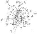
- the 1 to 3 illustrate a device V using the non-limiting example of a backflow trap R.
- the device is optionally designed for free installation or shaft installation and is generally used for wastewater management in a wastewater line.
- the device V has a housing 1 optionally designed on the outside with ribs 17 with at least substantially coaxial, that is to say slightly vertically offset pipe sockets 2, 3 for installation in a sewage line, the pipe sockets 2, 3 possibly defining a slope that is not emphasized relative to the housing 1 can.
- a housing 1 optionally designed on the outside with ribs 17 with at least substantially coaxial, that is to say slightly vertically offset pipe sockets 2, 3 for installation in a sewage line, the pipe sockets 2, 3 possibly defining a slope that is not emphasized relative to the housing 1 can.
- the lid In the embodiment shown, the lid carries additional devices, for example a one-hand lid locking and lifting bracket 5, as well as a pivotable locking lever 6, for example for locking an in Fig. 2 shown backflow flap 14 in its closed position on a sealing seat.
- a second backflow flap 13 is indicated with its seat as a further installation part, which is removably mounted in the housing 1.
- the cover 4 could carry a pump and / or a drive motor for the lever 6 or other additional equipment, or be free of additional equipment.
- the cover 4 is inserted, for example, with a nose (not shown) into an insertion pocket in the housing 1, in the direction of the arrows marked on an opening edge 8 of the inspection opening 30, until the cover is completely seated in the inspection opening 30, and then by pressing down the Lever 5 is locked.
- a nose not shown
- the flat opening edge 8 in the embodiment shown carries two bearing blocks 33 for the bracket 5 of the cover 4, and adjacent to the bearing blocks 33 on the long sides of the housing, each an engagement element 10 in the form of a tab projecting from the opening edge 8 with a straight inside here 18 and a cambered or convexly curved outer side 19.
- the outer side 19 can be chamfered or rounded towards the free end of the engagement element 10, so that the cross section decreases towards the free end.
- Longitudinal ends 20 of the engaging element 10 are optionally seated in the support elements 11 and, as indicated at 21, can be chamfered or rounded at the top for easier insertion.
- the engaging elements 10 which have an elongated, approximately rectangular cross-section with a length that is a multiple of the thickness, inserted into the chimney-like support elements 11 which stand up from the top of the cover, each of which engages around its engaging element 10 on all sides.
- the free ends of the engaging elements 10 lie approximately at the level of the free ends of the support elements 11.
- An insertion opening 22 leads to the inside of each support element 11 in the underside of the cover 4, which is extended upwards by the chimney-like support element 11 and has, for example, an approximately rectangular cross section Has.
- the opening edge 8 is delimited by an outer contour 9, in which, adjacent to the opening edge 8 via a narrow supporting edge 16, an outwardly open one in one plane (sealing plane E in Fig. 3 ), circumferential sealing groove 7 is formed. It limits the opening edge 8 an inner sealing surface 15 in the housing 1, which for cooperation with an in Fig. 3
- the radial seal 26 shown is seated in an outwardly open sealing groove 32 of a fold on the lower side of the cover 4.
- Fig. 1 and 2nd further show anchoring elements 16 molded into the ribs 17 on the outside of the housing 1, here, for example, just below the outer sealing groove 7.
- a sealing collar 25 of a shaft cup 28 inserted on the outside over the outer contour 9 is indicated, on which further shaft parts ( 5 to 7 ) can be mounted, and which can be fixed in the anchoring points 16 on the housing 1 or the stiffening ribs 17, optionally (shaft installation).
- each engagement element 10 in one piece at a distance from the outer contour 9 on the opening edge 8 is integrally formed, and that each support element 11 also maintains a distance from the outer contour 9, as well as an optionally provided support edge 24 of the cover 4, so that the sealing collar 25 can be guided past it without problems.
- Fig. 1 the two support elements 11 are connected by a transverse raised stiffening rib 12 on the upper side of the cover 4 to stiffen the cover 4 and provide mutual support.
- the support element 11 defines, so to speak, a chimney-like shaft 23 for the engagement of the inserted engagement element 10.
- the embodiment of the device V in Fig. 4 also a backflow trap R, differs from that of 1 to 3 due to a possibly larger size and a further one-hand lid locking and lifting bracket 5 ', which is pivotally mounted on the lid 4 in the opposite direction to the bracket 5 and serves for an additional locking of the lid 4 in the installation position shown (one-hand operation).
- brackets 5, 5 ' are swung up and the cover 4 is lifted out with one hand on both brackets 5, 5', for example until the aforementioned insertion lug emerges from the insertion pocket in the inspection opening and the cover can be lifted up at an angle.
- the insertion nose could be omitted.
- the length of engagement between the engagement elements 10 and the support elements 11 is expediently chosen to be longer than the lifting stroke of the cover 4 when it is removed from the inspection opening 30, so that the anti-buckling devices S can additionally take over the function of a guiding device for lifting out and also for inserting the cover 4.
- Fig. 5 is a side view of the device V, for example according to 1 to 3 combined with that already in Fig. 3 indicated shaft cup 28 (a circular cup with the slip or sealing edge 25 corresponding to the outer contour 9 of the opening edge 8 of the housing 1). Since the outer sealing groove 7 is only positioned just below the opening edge 8, a secure fixing of the manhole cup 28 is still possible even above the outer contours of the pipe sockets 3, 4, and consequently the housing 1 only needs to be raised slightly above the pipe sockets 3, 4 survive. The attached manhole cup 28 is additionally fixed in the anchoring points 16.
- Fig. 7 shows as a partial sectional view and in continuation of the shaft installation principle of Fig. 5 and 6 the device V, here in turn a backflow trap R, with the shaft cup 28 fixed thereon and the built-in parts 13, 14 in a shaft 29 consisting here of several shaft elements, closed on the upper side by a grate 31. Since the shaft 29 extends over a considerable height or it is important that for an inspection or maintenance the cover 4 at the bottom of the shaft 29 can be easily removed or used with the one-handed bracket 5 or the one-handed bracket 5, 5 ', since the access conditions may be unfavorable.
Description
Die Erfindung betrifft eine Vorrichtung der im Oberbegriff des Anspruchs 1 genannten Art.The invention relates to a device of the type mentioned in the preamble of
Solche Vorrichtungen, insbesondere Rückstauverschlüsse, sind von den Herstellern so konzipiert, dass sie entweder in freiem Einbau mit freiliegendem, ggf. Zusatzeinrichtungen tragendem Deckel oder im sogenannten Schachteinbau installierbar sind. Beim Schachteinbau ist der Deckel und sind die Zusatzeinrichtungen vom Inneren des Schachts her zugänglich, der auf einer am Gehäuse festgelegten Schachttasse aufgebaut ist.Such devices, in particular backflow stops, have been designed by the manufacturers in such a way that they can be installed either in free installation with an exposed cover, possibly carrying additional devices, or in so-called shaft installation. When installing the shaft, the cover and the additional devices are accessible from the inside of the shaft, which is installed on a shaft cup attached to the housing.
Bei einer gattungsgemäßen Vorrichtung, einem Rückstauverschluss für fäkalienfreies Abwasser, der von der Anmelderin seit Jahren unter dem Handelsnamen "Staufix" vertrieben wird, und ausschließlich für freien Einbau bestimmt ist, sind an den Längsseiten des Deckels nach unten ragende Leisten angeformt, die mit vier Exzenterverschlüssen bei montiertem Deckel von oben außen über eine angrenzend an den Öffnungsrand umlaufende Außenwand des Gehäuses greifen. Diese Außenwand wird unterseitig durch einen umlaufenden Falz begrenzt. Aufgabe dieser Beulsicherung ist es, bei Überdruck im Gehäuse, beispielsweise hervorgerufen durch eine Rückstausituation, zu verhindern, dass sich die Gehäusewand lokal ausbeult und die dort innen anliegende Deckeldichtung ihre Dichtfunktion verliert und Abwasser austritt. Die für den Eingriff der Leisten erforderliche Bauhöhe vergrößert die Abmessungen des Gehäuses in Hochrichtung unzweckmäßig. Außerdem verschmutzt das Gehäuse in diesen relativ großflächigen, teils hinterschnittenen Bereichen, bei längerer Gebrauchsdauer erheblich, so dass im Falle einer Inspektion oder einer Wartung oder eines Austausches von Einsatzteilen der Vorrichtung zunächst aufwändige Reinigungsarbeiten erforderlich sind, ehe der Deckel entfernt wird. Staufix für fäkalienhaltiges Abwasser wurde mit zusätzlichem baulichem Aufwand auch schon für Schachteinbau verwendet, z.B. in eine Bodenplatte einbetoniert.In a generic device, a backflow stop for faecal-free wastewater, which has been marketed by the applicant for years under the trade name "Staufix" and is intended exclusively for free installation, strips protruding downward on the long sides of the cover are formed, with four eccentric closures When the cover is installed, reach from the outside over an outer wall of the housing bordering the opening edge. This outer wall is delimited on the underside by a circumferential fold. The task of this anti-buckling device is to prevent overpressure in the housing, for example caused by a backflow situation, that the housing wall bulges locally and the cover seal located there loses its sealing function and waste water escapes. The overall height required for the engagement of the strips increases the dimensions of the housing in an unsuitable vertical direction. In addition, the housing becomes dirty in these relatively large areas, some of which are undercut, after a long period of use, so that in the event of an inspection or maintenance or replacement of insert parts of the device, complex cleaning work is required before the cover is removed. Staufix for waste water containing faeces has already been used for shaft installation with additional structural effort, e.g. concreted in a floor slab.
Die aus
Es ist ferner eine Rückstauverschluss-Vorrichtung auf dem Markt, bei der der Deckel umfangsseitig durch mehrere Schrauben festgelegt ist, die für ausreichende Querstabilität gegen eine Beulneigung der Gehäusewand sorgen und den Deckel abgedichtet festlegen. Diese Vorrichtung ist für einen Schachteinbau konzipiert, indem am Öffnungsrand des Gehäuses eine Schachttasse einstückig angeformt ist. Der Schacht selbst ist dann mit einer Radialdichtung innen in die Schachttasse eingesteckt und fixiert. Durch die angeformte Schachttasse hätte die Vorrichtung für freien Einbau unzweckmäßig große Abmessungen in Querrichtung, vor allem an den Längsseiten, weil die runde Schachttasse weit über das Gehäuse nach außen vorspringt. Außerdem hat das Gehäuse auch in Hochrichtung unzweckmäßig große Abmessungen, da sich die Schachttasse zum sicheren Einstecken des Schachts relativ weit nach oben über den Deckel erstreckt.There is also a backflow stop device on the market, in which the cover is fixed on the circumference by several screws, which ensure sufficient transverse stability against one Ensure the housing wall is inclined and fix the cover in a sealed manner. This device is designed for a shaft installation in that a shaft cup is integrally formed on the opening edge of the housing. The shaft itself is then inserted and fixed inside the shaft cup with a radial seal. Due to the molded manhole cup, the device for free installation would have unusually large dimensions in the transverse direction, especially on the long sides, because the round manhole cup protrudes outward far beyond the housing. In addition, the housing also has unusually large dimensions in the vertical direction, since the manhole cup extends relatively far up over the lid for the safe insertion of the manhole.
Der Erfindung liegt die Aufgabe zugrunde, eine Vorrichtung der eingangs genannten Art anzugeben, die bei gesteigerter Betriebssicherheit und kompakter Bauhöhe eine einfache Handhabung ermöglicht und wahlweise im freien Einbau oder im Schachteinbau innerhalb eines Abwasserstrangs installierbar ist.The invention is based on the object of specifying a device of the type mentioned at the outset which, with increased operational reliability and a compact overall height, enables simple handling and can optionally be installed in free installation or in a shaft installation within a sewage line.
Die gestellte Aufgabe wird mit den Merkmalen des Anspruchs 1 gelöst.The object is achieved with the features of
Die sozusagen in die Bauhöhe des Deckels integrierten Beulsicherungen wirken gleichermaßen bei Überdruck wie bei Unterdruck gegen unzweckmäßige Verformungen der Gehäusewand, die zu Undichtigkeiten oder Dichtungsschäden führen könnten. Obwohl ein großflächiger und langer Kontakt zwischen den Eingriffselementen und den Stützelementen gegeben ist, kann der Deckel nahezu bündig eingesetzt sein. Dennoch wird für die Beulsicherungs-Aufgabe unterhalb des Öffnungsrandes des Gehäuses keine Bauhöhe vergeudet. Vielmehr liegen im Deckelbereich und dort am Gehäuse nur minimale Flächen und/oder Höhen vor, an denen sich Verschmutzungen ablagern können, so dass für Inspektionen oder Wartungen leichte Reinigbarkeit gegeben ist. Die Handhabung ist einfach, weil beim Einsetzen des Deckels die Eingriffselemente sozusagen selbsttätig in die Stützelemente eindringen, dabei den Deckel führen. Der Deckel lässt sich auch wieder leicht ausheben, da die Stützelemente die Eingriffselemente allseits umfassen und somit Verschmutzungen oder Ablagerungen dort kaum Zutritt finden. Da die Beulsicherungen innerhalb der Außenkontur des Öffnungsrandes und oben im Deckel untergebracht sind, ist die gleiche Vorrichtung mit kompakten Abmessungen in Hoch- und Querrichtung nicht nur zum freien Einbau sondern wahlweise auch zum Schachteinbau einsetzbar, beispielsweise mit einer über die Außenkontur gesteckten Schachttasse für einen Schachtbau. Dabei weist bei der für wahlweisen Schachteinbau konzipierten, aber auch frei einbaubaren Vorrichtung, insbesondere einem Rückstauverschluss, das Gehäuse in der Außenkontur des Öffnungsrandes, beispielsweise über einen schmalen Stützrand angrenzend an den Öffnungsrand und die Beulsicherungen, eine umlaufende, nach außen offene Dichtungsnut für eine Schachttassen-Radialdichtung auf. Bei freiem Einbau der Vorrichtung stört die dann nicht benutzte Dichtungsnut nicht. Das Gehäuse wird dadurch nicht verbreitert und bleibt vor allem auch in Hochrichtung kompakt. Jedoch ist die Möglichkeit gegeben, im Schachteinbau die Dichtungsnut zum Unterbringen einer Radialdichtung zu nutzen.The bulge safeguards, so to speak, integrated into the overall height of the cover work against excess pressure as well as against negative pressure on the housing wall, which could lead to leaks or seal damage. Although there is a large and long contact between the engagement elements and the support elements, the cover can be inserted almost flush. Nevertheless, no height is wasted for the anti-buckling task below the opening edge of the housing. Rather, there are only minimal areas and / or heights on the cover area and there on the housing, on which dirt can accumulate, so that it is easy to clean for inspections or maintenance. Handling is easy because when the cover is inserted, the engaging elements automatically enter the support elements, so to speak, guiding the cover. The lid can also be easily lifted out again, since the support elements encompass the engagement elements on all sides, so that dirt or deposits hardly find access there. Since the bulge protection is housed inside the outer contour of the opening edge and at the top in the cover, the same device with compact dimensions in the vertical and transverse direction can be used not only for free installation but also optionally for shaft installation, for example with a shaft cup placed over the outer contour for a shaft construction . In the case of the device designed for optional shaft installation, but also freely installable, in particular a backflow stop, the housing in the outer contour of the opening edge, for example via a narrow support edge adjacent to the opening edge and the bulge protection, has a circumferential, outwardly open sealing groove for a shaft cup -Radial seal on. If the device is installed freely, the sealing groove that is then not used does not interfere. This does not widen the housing and, above all, remains compact in the vertical direction. However, it is possible to use the sealing groove in the shaft installation to accommodate a radial seal.
Um eine sichere Kraftübertragung, beispielsweise bei einer Überdrucksituation im Gehäuse sicherzustellen, ist es zweckmäßig, wenn sich das eingesteckte Eingriffselement zumindest bis zum freien Ende des Stützelementes erstreckt. Vorzugsweise ist hier eine gegenseitige Eingriffstiefe zwischen dem Stützelement und dem Eingriffselement gegeben, die größer als ein Aushebehub einer Deckel-Radialdichtung aus der Inspektionsöffnung ist. Dadurch wird beim Herausheben des Deckels den Beulsicherungen eine zusätzliche Aufgabe verliehen, nämlich für das ordnungsgemäße Austreten der Deckeldichtung zu sorgen, und beim Einsetzen des Deckels die Deckeldichtung ordnungsgemäß in das Gehäuse einzuführen, was insbesondere bei Schachteinbau mit gegebenenfalls komplizierten Zugangsmöglichkeiten wichtig sein kann.In order to ensure safe power transmission, for example in the event of an overpressure situation in the housing, it is expedient if the inserted engagement element extends at least to the free end of the support element. Preferably there is a mutual engagement depth between the support element and the engagement element, which is greater than a lifting stroke of a cover radial seal from the inspection opening. As a result, when the cover is lifted out, the buckling locks are given an additional task, namely to ensure that the cover seal emerges properly, and to insert the cover seal properly into the housing when inserting the cover, which can be particularly important when installing a shaft with possibly complicated access options.
Nach einem wichtigen Aspekt der Erfindung bilden die Ausbeulsicherungen aufgrund ihrer Ausbildung Führungsvorrichtungen zum Einbringen und Ausheben der an einem unterseitigen Falz des Deckels angeordneten Deckel-Radialdichtung in und aus der Inspektionsöffnung. Dies vereinfacht die Handhabung, insbesondere bei Schachteinbau der Vorrichtung.According to an important aspect of the invention, the bulge safeguards, due to their design, form guiding devices for inserting and lifting out the cover radial seal arranged on an underside fold of the cover into and out of the inspection opening. This simplifies handling, especially when the device is installed in the shaft.
Im Hinblick auf eine großflächige und stabile Kraftübertragung in jeder Beulsicherung, z.B. bei einer Überdruck- und/oder Unterdrucksituation im Gehäuse, ist es zweckmäßig, wenn das Eingriffselement einen annähernd rechteckigen, in Verlaufsrichtung der Längsseite des Öffnungsrandes langgestreckten Vollquerschnitt aufweist, dessen Länge ein Vielfaches der Stärke beträgt. Vorzugsweise, auch aus Entformungsgründen, kann der Querschnitt des Eingriffselements in Richtung zu seinem freien Ende allmählich abnehmen, kann die innere Seite gerade und kann die Außenseite konvex gekrümmt sein. Der Querschnitt der Einstecköffnung im Deckel sowie des kaminartigen Stützelementes kann hingegen rechteckig sein. Die konvexe Außenseite des Eingriffselementes kann zum freien Ende hin abgeschrägt oder abgerundet sein, um einen leichten Eintritt des Eingriffselementes in die Einstecköffnung sicherzustellen.With regard to large-area and stable power transmission in every anti-buckling device, e.g. in the event of an overpressure and / or underpressure situation in the housing, it is expedient if the engaging element has an approximately rectangular full cross section, elongated in the direction of the long side of the opening edge, the length of which is a multiple of the thickness. Preferably, also for demolding reasons, the cross section of the engagement element can gradually decrease towards its free end, the inner side can be straight and the outer side can be convexly curved. The cross section of the insertion opening in the lid and the chimney-like support element, however, can be rectangular. The convex outside of the engaging element can be chamfered or rounded towards the free end to ensure easy entry of the engaging element into the insertion opening.
Im Hinblick auf eine sichere Krafteinleitung und auch zur Aussteifung des fast bündig einsetzbaren Deckels kann es zweckmäßig sein, wenn sich gegenüberliegende Stützelemente der Beulsicherungen über eine an der Deckeloberseite eingegliederte, erhabene Versteifungsrippe verbunden sind.With a view to a safe introduction of force and also for stiffening the cover, which can be used almost flush, it can be expedient if opposing support elements of the anti-buckling devices are connected via a raised stiffening rib incorporated on the top side of the cover.
Zweckmäßig verläuft die Dichtungsnut in der Außenkontur des Öffnungsrandes in einer zum Öffnungsrand zumindest im Wesentlichen parallelen Dichtebene möglichst knapp unterhalb des Öffnungsrandes. Diese Dichtebene für die Schachttasse kann auf der gleichen Höhe liegen wie die Dichtebene des Deckels im Inneren der Inspektionsöffnung. Dadurch werden auch bei einem Schachteinbau großflächige und/oder hinterschnittene freiliegende Bereiche im Deckelbereich vermieden, in denen sich Verschmutzungen konzentriert absetzen könnten. In der Schachttasse kann die Deckeloberseite im Wesentlichen bündig mit dem Schachtgrund in der Schachttasse liegen, so dass sich dort kaum Verschmutzungen ablagern.The sealing groove in the outer contour of the opening edge expediently runs in a sealing plane which is at least substantially parallel to the opening edge, as close as possible to the bottom Opening edge. This sealing level for the manhole cup can be at the same height as the sealing level of the lid inside the inspection opening. This avoids large-area and / or undercut exposed areas in the cover area, in which dirt could settle in a concentrated manner, even when a shaft is installed. In the manhole cup, the top of the lid can lie essentially flush with the bottom of the manhole in the manhole cup, so that hardly any dirt is deposited there.
In einer Ausführungsform der Vorrichtung, insbesondere eines Rückstauverschlusses, weist das Gehäuse im Wesentlichen zum Öffnungsrand parallele und höhenversetzte Rohrstutzen auf, mit denen die Vorrichtung in einen Abwasserstrang eingliederbar ist. Das erfindungsgemäße Konzept ermöglicht es, dass die durch die außenliegende Dichtungsnut in der Außenkontur des Öffnungsrandes definierte Dichtebene zumindest für die Schachttasse oberhalb der Rohrstutzen des Gehäuses platziert ist, ohne dort zusätzliche Bauhöhe des Gehäuses in Kauf nehmen zu müssen.In one embodiment of the device, in particular a backflow stop, the housing has pipe connections which are parallel and offset in height, essentially parallel to the opening edge, by means of which the device can be incorporated into a sewage line. The concept according to the invention makes it possible for the sealing plane defined by the external sealing groove in the outer contour of the opening edge to be placed at least for the manhole cup above the pipe socket of the housing without having to accept the additional overall height of the housing there.
In einer Ausführungsform der Vorrichtung ist auf dem Gehäuse eine Schachttasse für einen die Vorrichtung zugänglich enthaltenden Schacht montiert. Die Schachttasse ist mit einem Haltekragen außen über die Außenkontur des Öffnungsrandes des Gehäuses gesteckt und wird in der durch die außenliegende Dichtungsnut definierten Dichtebene mittels einer in der Dichtungsnut angeordneten Radialdichtung abgedichtet. An der Außenseite des Gehäuses vorgesehene Verankerungsstellen ermöglichen die sichere Verankerung der abgedichteten Schachttasse am Gehäuse. Die Radialdichtung bietet den Vorteil, axiale Relativbewegungen zwischen dem Gehäuse und dem Schachtaufsatzteil zu schlucken bzw. bei der Montage oder Demontage ohne Schaden zu überstehen.In one embodiment of the device, a manhole cup for a manhole containing the device is mounted on the housing. The manhole cup is inserted with a holding collar on the outside over the outer contour of the opening edge of the housing and is sealed in the sealing plane defined by the sealing groove on the outside by means of a radial seal arranged in the sealing groove. Anchoring points provided on the outside of the housing enable the sealed shaft well to be securely anchored to the housing. The radial seal offers the advantage of swallowing relative axial movements between the housing and the shaft attachment part or of surviving without damage during assembly or disassembly.
Als Kern der Erfindung sind das Gehäuse und der Deckel der Vorrichtung so konzipiert, dass trotz der Beulsicherungen im Deckelrandbereich möglichst wenig Bauhöhe oder nach außen überstehende Teile vorliegen, und dennoch die Vorrichtung sowohl für freien Einbau als auch wahlweise Schachteinbau nutzbar ist.As the core of the invention, the housing and the lid of the device are designed in such a way that, despite the buckling protection in the lid edge area, there is as little structural height as possible or parts protruding to the outside, and yet the device can be used both for free installation and optional shaft installation.
Ausführungsformen des Erfindungsgegenstandes werden anhand der Zeichnung erläutert. Es zeigen:
- Fig. 1
- eine Perspektivansicht einer Vorrichtung mit festgelegtem Deckel in freiem Einbau,
- Fig. 2
- das Gehäuse der Vorrichtung von
Fig. 1 bei abgenommenem Deckel, - Fig. 3
- einen Detailschnitt in der Schnittebene III-III in
Fig. 1 , - Fig. 4
- eine Perspektivansicht einer weiteren Ausführungsform der Vorrichtung mit festgelegtem Deckel,
- Fig. 5
- eine Seitenansicht der Vorrichtung beispielsweise der
Fig. 1 ,2 und3 , vorbereitet für Schachteinbau, - Fig. 6
- eine Draufsicht auf die Vorrichtung von
Fig. 5 , und - Fig. 7
- eine Perspektivansicht, teilweise im Schnitt, einer Vorrichtung beispielsweise der
Fig. 1 im Schachteinbau.bis 4
- Fig. 1
- 1 shows a perspective view of a device with a fixed cover in free installation,
- Fig. 2
- the housing of the device from
Fig. 1 with the cover removed, - Fig. 3
- a detailed section in the section plane III-III in
Fig. 1 , - Fig. 4
- 2 shows a perspective view of a further embodiment of the device with a fixed cover,
- Fig. 5
- a side view of the device, for example the
Fig. 1 ,2nd and3rd , prepared for shaft installation, - Fig. 6
- a plan view of the device of
Fig. 5 , and - Fig. 7
- a perspective view, partly in section, of a device such as the
1 to 4 in the shaft installation.
Die
Die Vorrichtung V weist ein optional außen mit Rippen 17 gestaltetes Gehäuse 1 mit zumindest im Wesentlichen koaxialen, das heißt geringfügig höhenversetzten Rohrstutzen 2, 3 zum Installieren in einem Abwasserstrang auf, wobei die Rohrstutzen 2, 3 relativ zum Gehäuse 1 gegebenenfalls ein nicht hervorgehobenes Gefälle definieren können. In den
In der gezeigten Ausführungsform wird der Deckel 4 beispielsweise mit einer nicht gezeigten Nase in eine Einstecktasche im Gehäuse 1 eingeführt, in Richtung der auf einem Öffnungsrand 8 der Inspektionsöffnung 30 markierten Pfeile, bis der Deckel vollständig in der Inspektionsöffnung 30 sitzt, und dann durch Niederdrücken des Hebels 5 verriegelt wird. Hierbei ist, wie auch beim Herausheben des Deckels 4, eine bequeme Einhandbedienung möglich.In the embodiment shown, the
Der an sich ebene Öffnungsrand 8 trägt bei der gezeigten Ausführungsform zwei Lagerböcke 33 für den Bügel 5 des Deckels 4, sowie angrenzend an die Lagerböcke 33 an den Längsseiten des Gehäuses jeweils ein Eingriffselement 10 in Form einer vom Öffnungsrand 8 hochstehenden Lasche mit einer hier geraden Innenseite 18 und einer bombierten oder konvex gekrümmten Außenseite 19. Die Außenseite 19 kann zum freien Ende des Eingriffselementes 10 hin abgeschrägt oder abgerundet sein, so dass der Querschnitt zum freien Ende abnimmt. Längsenden 20 des Eingriffselementes 10 sitzen gegebenenfalls mit Spiel in den Stützelementen 11 und können, wie bei 21 angedeutet, zum leichteren Einführen oben abgeschrägt oder abgerundet sein.The flat opening edge 8 in the embodiment shown carries two bearing blocks 33 for the bracket 5 of the
In den
Der Öffnungsrand 8 wird durch eine Außenkontur 9 begrenzt, in der angrenzend an den Öffnungsrand 8 über einen schmalen Stützrand 16 eine nach außen offene, in einer Ebene (Dichtungsebene E in
In der Schnittdarstellung in
In
Die Ausführungsform der Vorrichtung V in
In beiden Ausführungsformen der
In der zu
Claims (8)
- Device (V) for guiding waste water, particularly a back flow stopper (R), comprising a housing (1) having a top side inspection opening (30) and an opening edge (8) defining an outer contour (9), and a cover lid (4) for being fixed in sealed fashion in the inspection opening (30), wherein form-fit buckling protections (S) are provided between the housing (1) and the cover lid (4), wherein as the respective protection (S) at least one upright standing engagement element (10) if provided at the opening edge (8) and at least one passing opening (22) is provided in the cover lid (4) including an upright standing supporting element (11) for the engagement element (10) in a chimney-like prolongation of the passing opening (22), the passing opening (22) and the supporting element (11) surrounding the inserted element (10) at all sides, and the engaging element (10) and the supporting element (11) being distant from the outer contour (9) of the opening edge (8), characterized in that for a selective shaft installation of the device (V) the outer contour (9) of the opening edge (8) comprises an outwardly open surrounding sealing groove (7) for mounting a shaft cup radial sealing (27), the sealing groove (7) being situated via a supporting edge (16) adjacently to the opening edge (8) and the buckling protections (S).
- Device according to claim 1, characterized in that the inserted engagement element (10) extends at least to the free end of the supporting element (11) with a mutual engagement overlap larger than a lifting stroke of a cover lid radial sealing (26) out of the inspection opening (30) at least through the free end of the supporting element (11).
- Device according to at least one of the preceding claim, characterized in that the buckling protections (S) form guiding devices for inserting and removing the cover lid radial sealing (26) into the and out of the inspection opening (30), the cover lid radial sealing (26) being arranged at a rebate (32) in the lower side of the cover lid (4).
- Device according to claim 1, characterized in that the engagement element (10) in the direction of the longitudinal side of the opening edge (8) with a substantially square and longitudinally extending full-cross section, the length of which amounts to a multiple of the thickness, wherein, preferably, the cross section gradually decreasing in the direction to the free end of the engagement element (10), the inner side of the engagement element (10) being straight and the outer side (19) being curved convexly, and that the inner cross section of the supporting element (11) is substantially square.
- Device according to at least one of the preceding claims, characterized in that supporting elements (11) being situated opposite to each other in relation to the inspection opening (30) are interconnected on the upper side of the cover lid by an incorporated reinforcing rib (12).
- Device according to claim 1, characterized in that the outwardly open sealing groove (7) extends in a sealing plane (E) of the housing (1) being substantially parallel to the opening edge (8), preferably, about at same height as the cover lid radial sealing (26) mounted at the inserted cover lid (4).
- Device according to at least one of the preceding claims, characterized in that the housing (1) has pipe sockets (3, 4) being substantially parallel to the opening edge (8) and being offset in height direction, and that the sealing plane (E) defined by the sealing groove (7) is placed above the contour of the pipe sockets (3, 4).
- Device according to at least one of the preceding claims, characterized that in that a shaft cup (28), preferably of a shaft (29) accessibly containing the device (V) is mounted on the housing (1), and that the shaft cup (28) is sealed via a holding collar (25) at the radial sealing (27) mounted in the sealing groove (7) and is secured in anchoring points (16) at the outer side of the housing (1).
Priority Applications (5)
| Application Number | Priority Date | Filing Date | Title |
|---|---|---|---|
| EP17151321.1A EP3348720B1 (en) | 2017-01-13 | 2017-01-13 | Device for conveying wastewater |
| RS20200882A RS60585B1 (en) | 2017-01-13 | 2017-01-13 | Device for conveying wastewater |
| PL17151321T PL3348720T3 (en) | 2017-01-13 | 2017-01-13 | Device for conveying wastewater |
| RU2017145137A RU2689481C1 (en) | 2017-01-13 | 2017-12-21 | Device for sewage |
| CN201810031514.1A CN108302224B (en) | 2017-01-13 | 2018-01-12 | Device for waste water engineering |
Applications Claiming Priority (1)
| Application Number | Priority Date | Filing Date | Title |
|---|---|---|---|
| EP17151321.1A EP3348720B1 (en) | 2017-01-13 | 2017-01-13 | Device for conveying wastewater |
Publications (2)
| Publication Number | Publication Date |
|---|---|
| EP3348720A1 EP3348720A1 (en) | 2018-07-18 |
| EP3348720B1 true EP3348720B1 (en) | 2020-04-29 |
Family
ID=57799582
Family Applications (1)
| Application Number | Title | Priority Date | Filing Date |
|---|---|---|---|
| EP17151321.1A Active EP3348720B1 (en) | 2017-01-13 | 2017-01-13 | Device for conveying wastewater |
Country Status (5)
| Country | Link |
|---|---|
| EP (1) | EP3348720B1 (en) |
| CN (1) | CN108302224B (en) |
| PL (1) | PL3348720T3 (en) |
| RS (1) | RS60585B1 (en) |
| RU (1) | RU2689481C1 (en) |
Family Cites Families (9)
| Publication number | Priority date | Publication date | Assignee | Title |
|---|---|---|---|---|
| DE1204143B (en) * | 1960-12-05 | 1965-10-28 | Standard Elektrik Lorenz Ag | One or two-part air shutoff flap of a pneumatic tube system |
| DE102005009777B4 (en) * | 2005-01-05 | 2008-08-21 | Aco Severin Ahlmann Gmbh & Co. Kg | backwater valve |
| US7325565B1 (en) * | 2005-03-23 | 2008-02-05 | Mizpah Lc | Backflow valve |
| CA2773442A1 (en) * | 2011-04-05 | 2012-10-05 | Back Water Boot Inc. | Check valve access chamber |
| CN203384428U (en) * | 2013-03-12 | 2014-01-08 | 李林林 | Sewer check valve |
| DE102014116435A1 (en) * | 2014-11-11 | 2016-05-12 | ACO Severin Ahlmann GmbH & Co Kommanditgesellschaft | backwater valve |
| DE102015109241B4 (en) * | 2015-06-11 | 2021-09-23 | ACO Severin Ahlmann GmbH & Co Kommanditgesellschaft | Backflow stop |
| CN204826163U (en) * | 2015-08-03 | 2015-12-02 | 张金荣 | Improvement structure of formula floor drain is inhaled to magnetism |
| RU167039U1 (en) * | 2016-02-24 | 2016-12-20 | Андрей Вячеславович Кононов | SEWAGE TREATMENT PLANT |
-
2017
- 2017-01-13 EP EP17151321.1A patent/EP3348720B1/en active Active
- 2017-01-13 PL PL17151321T patent/PL3348720T3/en unknown
- 2017-01-13 RS RS20200882A patent/RS60585B1/en unknown
- 2017-12-21 RU RU2017145137A patent/RU2689481C1/en not_active IP Right Cessation
-
2018
- 2018-01-12 CN CN201810031514.1A patent/CN108302224B/en active Active
Non-Patent Citations (1)
| Title |
|---|
| None * |
Also Published As
| Publication number | Publication date |
|---|---|
| CN108302224A (en) | 2018-07-20 |
| RU2689481C1 (en) | 2019-05-28 |
| CN108302224B (en) | 2019-10-25 |
| RS60585B1 (en) | 2020-08-31 |
| PL3348720T3 (en) | 2020-11-02 |
| EP3348720A1 (en) | 2018-07-18 |
Similar Documents
| Publication | Publication Date | Title |
|---|---|---|
| DE102006034943A1 (en) | Filter system for fluids | |
| DE202011051140U1 (en) | Cover box for a shower drain system | |
| EP3448732B1 (en) | Suction device for a wastewater tank, retrofit kit therefor and method for emptying a wastewatertank | |
| EP2113614B1 (en) | Drain device | |
| DE202012105045U1 (en) | Shower tray with a sloping floor surface | |
| EP2300712B1 (en) | Hydraulic aggregate | |
| WO2005111318A1 (en) | Protective rib | |
| EP3348720B1 (en) | Device for conveying wastewater | |
| EP1754834A1 (en) | Cover frame for a manhole | |
| EP2570559B1 (en) | Drainage channel | |
| DE102010021294A1 (en) | Underground shaft for power distribution and / or telecommunications | |
| EP2218831B1 (en) | Street shaft cover with a mounting support for helping means for climbing into the shaft | |
| EP3605763B1 (en) | Underfloor shaft, in particular for energy distribution and/or telecommunication | |
| EP2735348A1 (en) | Separator with support structure | |
| DE102013111181A1 (en) | Grate for drip pans for storage of containers, tanks, barrels and canisters | |
| EP2425064B1 (en) | Siphon and item of furniture | |
| EP2348160B1 (en) | Outlet sluice for a renovated opening of a sanitary reservoir | |
| DE102019001754A1 (en) | Siphon device | |
| DE2948050C2 (en) | Floor drain | |
| DE3628703C2 (en) | Opening device for covers of floor openings, in particular for inspection openings of sewage systems | |
| EP2776640B1 (en) | Floor drain device | |
| DE102022103781A1 (en) | Bait holding device and road drain | |
| EP2573285A1 (en) | Waste water hoisting facility | |
| DE102013017569A1 (en) | shower floor | |
| DE202020003298U1 (en) | Water drainage device |
Legal Events
| Date | Code | Title | Description |
|---|---|---|---|
| PUAI | Public reference made under article 153(3) epc to a published international application that has entered the european phase |
Free format text: ORIGINAL CODE: 0009012 |
|
| STAA | Information on the status of an ep patent application or granted ep patent |
Free format text: STATUS: THE APPLICATION HAS BEEN PUBLISHED |
|
| AK | Designated contracting states |
Kind code of ref document: A1 Designated state(s): AL AT BE BG CH CY CZ DE DK EE ES FI FR GB GR HR HU IE IS IT LI LT LU LV MC MK MT NL NO PL PT RO RS SE SI SK SM TR |
|
| AX | Request for extension of the european patent |
Extension state: BA ME |
|
| STAA | Information on the status of an ep patent application or granted ep patent |
Free format text: STATUS: REQUEST FOR EXAMINATION WAS MADE |
|
| 17P | Request for examination filed |
Effective date: 20181127 |
|
| RBV | Designated contracting states (corrected) |
Designated state(s): AL AT BE BG CH CY CZ DE DK EE ES FI FR GB GR HR HU IE IS IT LI LT LU LV MC MK MT NL NO PL PT RO RS SE SI SK SM TR |
|
| GRAP | Despatch of communication of intention to grant a patent |
Free format text: ORIGINAL CODE: EPIDOSNIGR1 |
|
| STAA | Information on the status of an ep patent application or granted ep patent |
Free format text: STATUS: GRANT OF PATENT IS INTENDED |
|
| INTG | Intention to grant announced |
Effective date: 20191121 |
|
| GRAS | Grant fee paid |
Free format text: ORIGINAL CODE: EPIDOSNIGR3 |
|
| GRAA | (expected) grant |
Free format text: ORIGINAL CODE: 0009210 |
|
| STAA | Information on the status of an ep patent application or granted ep patent |
Free format text: STATUS: THE PATENT HAS BEEN GRANTED |
|
| AK | Designated contracting states |
Kind code of ref document: B1 Designated state(s): AL AT BE BG CH CY CZ DE DK EE ES FI FR GB GR HR HU IE IS IT LI LT LU LV MC MK MT NL NO PL PT RO RS SE SI SK SM TR |
|
| REG | Reference to a national code |
Ref country code: GB Ref legal event code: FG4D Free format text: NOT ENGLISH |
|
| REG | Reference to a national code |
Ref country code: CH Ref legal event code: EP |
|
| REG | Reference to a national code |
Ref country code: DE Ref legal event code: R096 Ref document number: 502017004919 Country of ref document: DE |
|
| REG | Reference to a national code |
Ref country code: AT Ref legal event code: REF Ref document number: 1263495 Country of ref document: AT Kind code of ref document: T Effective date: 20200515 |
|
| REG | Reference to a national code |
Ref country code: IE Ref legal event code: FG4D Free format text: LANGUAGE OF EP DOCUMENT: GERMAN |
|
| REG | Reference to a national code |
Ref country code: NL Ref legal event code: MP Effective date: 20200429 |
|
| REG | Reference to a national code |
Ref country code: LT Ref legal event code: MG4D |
|
| PG25 | Lapsed in a contracting state [announced via postgrant information from national office to epo] |
Ref country code: NO Free format text: LAPSE BECAUSE OF FAILURE TO SUBMIT A TRANSLATION OF THE DESCRIPTION OR TO PAY THE FEE WITHIN THE PRESCRIBED TIME-LIMIT Effective date: 20200729 Ref country code: LT Free format text: LAPSE BECAUSE OF FAILURE TO SUBMIT A TRANSLATION OF THE DESCRIPTION OR TO PAY THE FEE WITHIN THE PRESCRIBED TIME-LIMIT Effective date: 20200429 Ref country code: FI Free format text: LAPSE BECAUSE OF FAILURE TO SUBMIT A TRANSLATION OF THE DESCRIPTION OR TO PAY THE FEE WITHIN THE PRESCRIBED TIME-LIMIT Effective date: 20200429 Ref country code: PT Free format text: LAPSE BECAUSE OF FAILURE TO SUBMIT A TRANSLATION OF THE DESCRIPTION OR TO PAY THE FEE WITHIN THE PRESCRIBED TIME-LIMIT Effective date: 20200831 Ref country code: IS Free format text: LAPSE BECAUSE OF FAILURE TO SUBMIT A TRANSLATION OF THE DESCRIPTION OR TO PAY THE FEE WITHIN THE PRESCRIBED TIME-LIMIT Effective date: 20200829 Ref country code: SE Free format text: LAPSE BECAUSE OF FAILURE TO SUBMIT A TRANSLATION OF THE DESCRIPTION OR TO PAY THE FEE WITHIN THE PRESCRIBED TIME-LIMIT Effective date: 20200429 Ref country code: GR Free format text: LAPSE BECAUSE OF FAILURE TO SUBMIT A TRANSLATION OF THE DESCRIPTION OR TO PAY THE FEE WITHIN THE PRESCRIBED TIME-LIMIT Effective date: 20200730 |
|
| PG25 | Lapsed in a contracting state [announced via postgrant information from national office to epo] |
Ref country code: HR Free format text: LAPSE BECAUSE OF FAILURE TO SUBMIT A TRANSLATION OF THE DESCRIPTION OR TO PAY THE FEE WITHIN THE PRESCRIBED TIME-LIMIT Effective date: 20200429 Ref country code: LV Free format text: LAPSE BECAUSE OF FAILURE TO SUBMIT A TRANSLATION OF THE DESCRIPTION OR TO PAY THE FEE WITHIN THE PRESCRIBED TIME-LIMIT Effective date: 20200429 Ref country code: BG Free format text: LAPSE BECAUSE OF FAILURE TO SUBMIT A TRANSLATION OF THE DESCRIPTION OR TO PAY THE FEE WITHIN THE PRESCRIBED TIME-LIMIT Effective date: 20200729 |
|
| PG25 | Lapsed in a contracting state [announced via postgrant information from national office to epo] |
Ref country code: AL Free format text: LAPSE BECAUSE OF FAILURE TO SUBMIT A TRANSLATION OF THE DESCRIPTION OR TO PAY THE FEE WITHIN THE PRESCRIBED TIME-LIMIT Effective date: 20200429 Ref country code: NL Free format text: LAPSE BECAUSE OF FAILURE TO SUBMIT A TRANSLATION OF THE DESCRIPTION OR TO PAY THE FEE WITHIN THE PRESCRIBED TIME-LIMIT Effective date: 20200429 |
|
| PG25 | Lapsed in a contracting state [announced via postgrant information from national office to epo] |
Ref country code: CZ Free format text: LAPSE BECAUSE OF FAILURE TO SUBMIT A TRANSLATION OF THE DESCRIPTION OR TO PAY THE FEE WITHIN THE PRESCRIBED TIME-LIMIT Effective date: 20200429 Ref country code: ES Free format text: LAPSE BECAUSE OF FAILURE TO SUBMIT A TRANSLATION OF THE DESCRIPTION OR TO PAY THE FEE WITHIN THE PRESCRIBED TIME-LIMIT Effective date: 20200429 Ref country code: RO Free format text: LAPSE BECAUSE OF FAILURE TO SUBMIT A TRANSLATION OF THE DESCRIPTION OR TO PAY THE FEE WITHIN THE PRESCRIBED TIME-LIMIT Effective date: 20200429 Ref country code: DK Free format text: LAPSE BECAUSE OF FAILURE TO SUBMIT A TRANSLATION OF THE DESCRIPTION OR TO PAY THE FEE WITHIN THE PRESCRIBED TIME-LIMIT Effective date: 20200429 Ref country code: EE Free format text: LAPSE BECAUSE OF FAILURE TO SUBMIT A TRANSLATION OF THE DESCRIPTION OR TO PAY THE FEE WITHIN THE PRESCRIBED TIME-LIMIT Effective date: 20200429 Ref country code: SM Free format text: LAPSE BECAUSE OF FAILURE TO SUBMIT A TRANSLATION OF THE DESCRIPTION OR TO PAY THE FEE WITHIN THE PRESCRIBED TIME-LIMIT Effective date: 20200429 |
|
| REG | Reference to a national code |
Ref country code: DE Ref legal event code: R097 Ref document number: 502017004919 Country of ref document: DE |
|
| PG25 | Lapsed in a contracting state [announced via postgrant information from national office to epo] |
Ref country code: SK Free format text: LAPSE BECAUSE OF FAILURE TO SUBMIT A TRANSLATION OF THE DESCRIPTION OR TO PAY THE FEE WITHIN THE PRESCRIBED TIME-LIMIT Effective date: 20200429 |
|
| PLBE | No opposition filed within time limit |
Free format text: ORIGINAL CODE: 0009261 |
|
| STAA | Information on the status of an ep patent application or granted ep patent |
Free format text: STATUS: NO OPPOSITION FILED WITHIN TIME LIMIT |
|
| 26N | No opposition filed |
Effective date: 20210201 |
|
| PG25 | Lapsed in a contracting state [announced via postgrant information from national office to epo] |
Ref country code: SI Free format text: LAPSE BECAUSE OF FAILURE TO SUBMIT A TRANSLATION OF THE DESCRIPTION OR TO PAY THE FEE WITHIN THE PRESCRIBED TIME-LIMIT Effective date: 20200429 |
|
| PG25 | Lapsed in a contracting state [announced via postgrant information from national office to epo] |
Ref country code: MC Free format text: LAPSE BECAUSE OF FAILURE TO SUBMIT A TRANSLATION OF THE DESCRIPTION OR TO PAY THE FEE WITHIN THE PRESCRIBED TIME-LIMIT Effective date: 20200429 |
|
| REG | Reference to a national code |
Ref country code: CH Ref legal event code: PL |
|
| GBPC | Gb: european patent ceased through non-payment of renewal fee |
Effective date: 20210113 |
|
| PG25 | Lapsed in a contracting state [announced via postgrant information from national office to epo] |
Ref country code: LU Free format text: LAPSE BECAUSE OF NON-PAYMENT OF DUE FEES Effective date: 20210113 |
|
| REG | Reference to a national code |
Ref country code: BE Ref legal event code: MM Effective date: 20210131 |
|
| PG25 | Lapsed in a contracting state [announced via postgrant information from national office to epo] |
Ref country code: FR Free format text: LAPSE BECAUSE OF NON-PAYMENT OF DUE FEES Effective date: 20210131 |
|
| PG25 | Lapsed in a contracting state [announced via postgrant information from national office to epo] |
Ref country code: CH Free format text: LAPSE BECAUSE OF NON-PAYMENT OF DUE FEES Effective date: 20210131 Ref country code: LI Free format text: LAPSE BECAUSE OF NON-PAYMENT OF DUE FEES Effective date: 20210131 Ref country code: GB Free format text: LAPSE BECAUSE OF NON-PAYMENT OF DUE FEES Effective date: 20210113 |
|
| PG25 | Lapsed in a contracting state [announced via postgrant information from national office to epo] |
Ref country code: IE Free format text: LAPSE BECAUSE OF NON-PAYMENT OF DUE FEES Effective date: 20210113 |
|
| PG25 | Lapsed in a contracting state [announced via postgrant information from national office to epo] |
Ref country code: BE Free format text: LAPSE BECAUSE OF NON-PAYMENT OF DUE FEES Effective date: 20210131 |
|
| PGFP | Annual fee paid to national office [announced via postgrant information from national office to epo] |
Ref country code: PL Payment date: 20221228 Year of fee payment: 7 |
|
| PGFP | Annual fee paid to national office [announced via postgrant information from national office to epo] |
Ref country code: AT Payment date: 20230124 Year of fee payment: 7 |
|
| PGFP | Annual fee paid to national office [announced via postgrant information from national office to epo] |
Ref country code: IT Payment date: 20230131 Year of fee payment: 7 Ref country code: DE Payment date: 20230126 Year of fee payment: 7 |
|
| PG25 | Lapsed in a contracting state [announced via postgrant information from national office to epo] |
Ref country code: CY Free format text: LAPSE BECAUSE OF FAILURE TO SUBMIT A TRANSLATION OF THE DESCRIPTION OR TO PAY THE FEE WITHIN THE PRESCRIBED TIME-LIMIT Effective date: 20200429 |
|
| PG25 | Lapsed in a contracting state [announced via postgrant information from national office to epo] |
Ref country code: HU Free format text: LAPSE BECAUSE OF FAILURE TO SUBMIT A TRANSLATION OF THE DESCRIPTION OR TO PAY THE FEE WITHIN THE PRESCRIBED TIME-LIMIT; INVALID AB INITIO Effective date: 20170113 |
|
| PGFP | Annual fee paid to national office [announced via postgrant information from national office to epo] |
Ref country code: RS Payment date: 20231219 Year of fee payment: 8 |
|
| PGFP | Annual fee paid to national office [announced via postgrant information from national office to epo] |
Ref country code: PL Payment date: 20231221 Year of fee payment: 8 |
|
| PGFP | Annual fee paid to national office [announced via postgrant information from national office to epo] |
Ref country code: AT Payment date: 20240124 Year of fee payment: 8 |