EP3348324B1 - Cartouche et méthode pour l'élimination de l'humidité de l'air atmosphérique - Google Patents
Cartouche et méthode pour l'élimination de l'humidité de l'air atmosphérique Download PDFInfo
- Publication number
- EP3348324B1 EP3348324B1 EP17192448.3A EP17192448A EP3348324B1 EP 3348324 B1 EP3348324 B1 EP 3348324B1 EP 17192448 A EP17192448 A EP 17192448A EP 3348324 B1 EP3348324 B1 EP 3348324B1
- Authority
- EP
- European Patent Office
- Prior art keywords
- liquid
- ozonation
- cartridge
- gas
- ozone
- Prior art date
- Legal status (The legal status is an assumption and is not a legal conclusion. Google has not performed a legal analysis and makes no representation as to the accuracy of the status listed.)
- Active
Links
- 238000000034 method Methods 0.000 title claims description 24
- 238000006385 ozonation reaction Methods 0.000 claims description 247
- CBENFWSGALASAD-UHFFFAOYSA-N Ozone Chemical compound [O-][O+]=O CBENFWSGALASAD-UHFFFAOYSA-N 0.000 claims description 152
- IJGRMHOSHXDMSA-UHFFFAOYSA-N Atomic nitrogen Chemical compound N#N IJGRMHOSHXDMSA-UHFFFAOYSA-N 0.000 claims description 34
- 239000000463 material Substances 0.000 claims description 32
- 239000002274 desiccant Substances 0.000 claims description 26
- QVGXLLKOCUKJST-UHFFFAOYSA-N atomic oxygen Chemical compound [O] QVGXLLKOCUKJST-UHFFFAOYSA-N 0.000 claims description 24
- 239000001301 oxygen Substances 0.000 claims description 24
- 229910052760 oxygen Inorganic materials 0.000 claims description 24
- 238000004891 communication Methods 0.000 claims description 19
- 230000004044 response Effects 0.000 claims description 19
- 229910052757 nitrogen Inorganic materials 0.000 claims description 16
- 230000010354 integration Effects 0.000 claims description 8
- 239000007788 liquid Substances 0.000 description 491
- 239000007789 gas Substances 0.000 description 158
- XLYOFNOQVPJJNP-UHFFFAOYSA-N water Substances O XLYOFNOQVPJJNP-UHFFFAOYSA-N 0.000 description 153
- 239000012530 fluid Substances 0.000 description 48
- 238000002156 mixing Methods 0.000 description 27
- 230000003134 recirculating effect Effects 0.000 description 20
- 239000000203 mixture Substances 0.000 description 16
- 241001354243 Corona Species 0.000 description 12
- 238000011012 sanitization Methods 0.000 description 11
- 230000001965 increasing effect Effects 0.000 description 10
- 230000033116 oxidation-reduction process Effects 0.000 description 9
- 230000001419 dependent effect Effects 0.000 description 7
- 239000000654 additive Substances 0.000 description 6
- 230000006378 damage Effects 0.000 description 6
- 230000000249 desinfective effect Effects 0.000 description 6
- 230000006870 function Effects 0.000 description 6
- 238000000926 separation method Methods 0.000 description 6
- 239000000243 solution Substances 0.000 description 6
- 238000012546 transfer Methods 0.000 description 6
- 238000004140 cleaning Methods 0.000 description 5
- MYMOFIZGZYHOMD-UHFFFAOYSA-N Dioxygen Chemical compound O=O MYMOFIZGZYHOMD-UHFFFAOYSA-N 0.000 description 4
- 238000010586 diagram Methods 0.000 description 4
- 229910001882 dioxygen Inorganic materials 0.000 description 4
- 230000009969 flowable effect Effects 0.000 description 4
- 239000010902 straw Substances 0.000 description 4
- QTBSBXVTEAMEQO-UHFFFAOYSA-N Acetic acid Chemical compound CC(O)=O QTBSBXVTEAMEQO-UHFFFAOYSA-N 0.000 description 3
- 241000894006 Bacteria Species 0.000 description 3
- ZAMOUSCENKQFHK-UHFFFAOYSA-N Chlorine atom Chemical compound [Cl] ZAMOUSCENKQFHK-UHFFFAOYSA-N 0.000 description 3
- 230000008859 change Effects 0.000 description 3
- 239000000460 chlorine Substances 0.000 description 3
- 229910052801 chlorine Inorganic materials 0.000 description 3
- 238000000354 decomposition reaction Methods 0.000 description 3
- 238000007872 degassing Methods 0.000 description 3
- 239000000645 desinfectant Substances 0.000 description 3
- 230000003647 oxidation Effects 0.000 description 3
- 238000007254 oxidation reaction Methods 0.000 description 3
- 230000001590 oxidative effect Effects 0.000 description 3
- 238000005201 scrubbing Methods 0.000 description 3
- OKTJSMMVPCPJKN-UHFFFAOYSA-N Carbon Chemical compound [C] OKTJSMMVPCPJKN-UHFFFAOYSA-N 0.000 description 2
- KFSLWBXXFJQRDL-UHFFFAOYSA-N Peracetic acid Chemical compound CC(=O)OO KFSLWBXXFJQRDL-UHFFFAOYSA-N 0.000 description 2
- 230000008901 benefit Effects 0.000 description 2
- 230000033228 biological regulation Effects 0.000 description 2
- 239000003054 catalyst Substances 0.000 description 2
- 238000006243 chemical reaction Methods 0.000 description 2
- 239000003795 chemical substances by application Substances 0.000 description 2
- 229910001873 dinitrogen Inorganic materials 0.000 description 2
- 238000007599 discharging Methods 0.000 description 2
- 238000001914 filtration Methods 0.000 description 2
- NUJOXMJBOLGQSY-UHFFFAOYSA-N manganese dioxide Chemical group O=[Mn]=O NUJOXMJBOLGQSY-UHFFFAOYSA-N 0.000 description 2
- 230000004048 modification Effects 0.000 description 2
- 238000012986 modification Methods 0.000 description 2
- 239000003921 oil Substances 0.000 description 2
- 239000003960 organic solvent Substances 0.000 description 2
- 239000007800 oxidant agent Substances 0.000 description 2
- 238000007789 sealing Methods 0.000 description 2
- PXGOKWXKJXAPGV-UHFFFAOYSA-N Fluorine Chemical compound FF PXGOKWXKJXAPGV-UHFFFAOYSA-N 0.000 description 1
- 241000233866 Fungi Species 0.000 description 1
- 240000004808 Saccharomyces cerevisiae Species 0.000 description 1
- 238000009825 accumulation Methods 0.000 description 1
- 230000009471 action Effects 0.000 description 1
- 230000000996 additive effect Effects 0.000 description 1
- 238000007605 air drying Methods 0.000 description 1
- 230000004075 alteration Effects 0.000 description 1
- 238000013459 approach Methods 0.000 description 1
- 239000007864 aqueous solution Substances 0.000 description 1
- 230000009286 beneficial effect Effects 0.000 description 1
- 239000003638 chemical reducing agent Substances 0.000 description 1
- 238000001514 detection method Methods 0.000 description 1
- PUFKGWVZPFANLN-UHFFFAOYSA-N dioxomanganese oxocopper Chemical compound O=[Cu].O=[Mn]=O PUFKGWVZPFANLN-UHFFFAOYSA-N 0.000 description 1
- 238000006073 displacement reaction Methods 0.000 description 1
- 238000004090 dissolution Methods 0.000 description 1
- 239000003623 enhancer Substances 0.000 description 1
- 239000011737 fluorine Substances 0.000 description 1
- 229910052731 fluorine Inorganic materials 0.000 description 1
- 235000013305 food Nutrition 0.000 description 1
- 239000013505 freshwater Substances 0.000 description 1
- 238000010438 heat treatment Methods 0.000 description 1
- 239000001257 hydrogen Substances 0.000 description 1
- 229910052739 hydrogen Inorganic materials 0.000 description 1
- 125000004435 hydrogen atom Chemical class [H]* 0.000 description 1
- 230000001939 inductive effect Effects 0.000 description 1
- 238000010297 mechanical methods and process Methods 0.000 description 1
- 230000007246 mechanism Effects 0.000 description 1
- 230000007659 motor function Effects 0.000 description 1
- 230000003287 optical effect Effects 0.000 description 1
- 150000002978 peroxides Chemical class 0.000 description 1
- 230000008569 process Effects 0.000 description 1
- 238000012545 processing Methods 0.000 description 1
- 230000009257 reactivity Effects 0.000 description 1
- 238000004064 recycling Methods 0.000 description 1
- 230000009467 reduction Effects 0.000 description 1
- 230000001105 regulatory effect Effects 0.000 description 1
- 238000012552 review Methods 0.000 description 1
- 230000001954 sterilising effect Effects 0.000 description 1
- 239000000126 substance Substances 0.000 description 1
- 230000002459 sustained effect Effects 0.000 description 1
- 238000012360 testing method Methods 0.000 description 1
- 238000011144 upstream manufacturing Methods 0.000 description 1
- 230000008016 vaporization Effects 0.000 description 1
- 235000013311 vegetables Nutrition 0.000 description 1
Images


Classifications
-
- B—PERFORMING OPERATIONS; TRANSPORTING
- B01—PHYSICAL OR CHEMICAL PROCESSES OR APPARATUS IN GENERAL
- B01D—SEPARATION
- B01D19/00—Degasification of liquids
- B01D19/0042—Degasification of liquids modifying the liquid flow
- B01D19/0052—Degasification of liquids modifying the liquid flow in rotating vessels, vessels containing movable parts or in which centrifugal movement is caused
- B01D19/0057—Degasification of liquids modifying the liquid flow in rotating vessels, vessels containing movable parts or in which centrifugal movement is caused the centrifugal movement being caused by a vortex, e.g. using a cyclone, or by a tangential inlet
-
- B—PERFORMING OPERATIONS; TRANSPORTING
- B01—PHYSICAL OR CHEMICAL PROCESSES OR APPARATUS IN GENERAL
- B01F—MIXING, e.g. DISSOLVING, EMULSIFYING OR DISPERSING
- B01F23/00—Mixing according to the phases to be mixed, e.g. dispersing or emulsifying
- B01F23/20—Mixing gases with liquids
- B01F23/23—Mixing gases with liquids by introducing gases into liquid media, e.g. for producing aerated liquids
- B01F23/232—Mixing gases with liquids by introducing gases into liquid media, e.g. for producing aerated liquids using flow-mixing means for introducing the gases, e.g. baffles
- B01F23/2323—Mixing gases with liquids by introducing gases into liquid media, e.g. for producing aerated liquids using flow-mixing means for introducing the gases, e.g. baffles by circulating the flow in guiding constructions or conduits
-
- B—PERFORMING OPERATIONS; TRANSPORTING
- B01—PHYSICAL OR CHEMICAL PROCESSES OR APPARATUS IN GENERAL
- B01F—MIXING, e.g. DISSOLVING, EMULSIFYING OR DISPERSING
- B01F23/00—Mixing according to the phases to be mixed, e.g. dispersing or emulsifying
- B01F23/20—Mixing gases with liquids
- B01F23/23—Mixing gases with liquids by introducing gases into liquid media, e.g. for producing aerated liquids
- B01F23/237—Mixing gases with liquids by introducing gases into liquid media, e.g. for producing aerated liquids characterised by the physical or chemical properties of gases or vapours introduced in the liquid media
- B01F23/2376—Mixing gases with liquids by introducing gases into liquid media, e.g. for producing aerated liquids characterised by the physical or chemical properties of gases or vapours introduced in the liquid media characterised by the gas being introduced
- B01F23/23761—Aerating, i.e. introducing oxygen containing gas in liquids
- B01F23/237613—Ozone
-
- B—PERFORMING OPERATIONS; TRANSPORTING
- B01—PHYSICAL OR CHEMICAL PROCESSES OR APPARATUS IN GENERAL
- B01F—MIXING, e.g. DISSOLVING, EMULSIFYING OR DISPERSING
- B01F25/00—Flow mixers; Mixers for falling materials, e.g. solid particles
- B01F25/10—Mixing by creating a vortex flow, e.g. by tangential introduction of flow components
- B01F25/103—Mixing by creating a vortex flow, e.g. by tangential introduction of flow components with additional mixing means other than vortex mixers, e.g. the vortex chamber being positioned in another mixing chamber
-
- B—PERFORMING OPERATIONS; TRANSPORTING
- B01—PHYSICAL OR CHEMICAL PROCESSES OR APPARATUS IN GENERAL
- B01F—MIXING, e.g. DISSOLVING, EMULSIFYING OR DISPERSING
- B01F25/00—Flow mixers; Mixers for falling materials, e.g. solid particles
- B01F25/40—Static mixers
- B01F25/45—Mixers in which the materials to be mixed are pressed together through orifices or interstitial spaces, e.g. between beads
- B01F25/452—Mixers in which the materials to be mixed are pressed together through orifices or interstitial spaces, e.g. between beads characterised by elements provided with orifices or interstitial spaces
- B01F25/4523—Mixers in which the materials to be mixed are pressed together through orifices or interstitial spaces, e.g. between beads characterised by elements provided with orifices or interstitial spaces the components being pressed through sieves, screens or meshes which obstruct the whole diameter of the tube
- B01F25/45231—Mixers in which the materials to be mixed are pressed together through orifices or interstitial spaces, e.g. between beads characterised by elements provided with orifices or interstitial spaces the components being pressed through sieves, screens or meshes which obstruct the whole diameter of the tube the sieves, screens or meshes being cylinders or cones which obstruct the whole diameter of the tube, the flow changing from axial in radial and again in axial
-
- C—CHEMISTRY; METALLURGY
- C02—TREATMENT OF WATER, WASTE WATER, SEWAGE, OR SLUDGE
- C02F—TREATMENT OF WATER, WASTE WATER, SEWAGE, OR SLUDGE
- C02F1/00—Treatment of water, waste water, or sewage
- C02F1/20—Treatment of water, waste water, or sewage by degassing, i.e. liberation of dissolved gases
-
- C—CHEMISTRY; METALLURGY
- C02—TREATMENT OF WATER, WASTE WATER, SEWAGE, OR SLUDGE
- C02F—TREATMENT OF WATER, WASTE WATER, SEWAGE, OR SLUDGE
- C02F1/00—Treatment of water, waste water, or sewage
- C02F1/72—Treatment of water, waste water, or sewage by oxidation
- C02F1/78—Treatment of water, waste water, or sewage by oxidation with ozone
-
- B—PERFORMING OPERATIONS; TRANSPORTING
- B01—PHYSICAL OR CHEMICAL PROCESSES OR APPARATUS IN GENERAL
- B01F—MIXING, e.g. DISSOLVING, EMULSIFYING OR DISPERSING
- B01F23/00—Mixing according to the phases to be mixed, e.g. dispersing or emulsifying
- B01F23/20—Mixing gases with liquids
- B01F23/23—Mixing gases with liquids by introducing gases into liquid media, e.g. for producing aerated liquids
-
- B—PERFORMING OPERATIONS; TRANSPORTING
- B01—PHYSICAL OR CHEMICAL PROCESSES OR APPARATUS IN GENERAL
- B01F—MIXING, e.g. DISSOLVING, EMULSIFYING OR DISPERSING
- B01F25/00—Flow mixers; Mixers for falling materials, e.g. solid particles
- B01F25/30—Injector mixers
- B01F25/31—Injector mixers in conduits or tubes through which the main component flows
- B01F25/312—Injector mixers in conduits or tubes through which the main component flows with Venturi elements; Details thereof
-
- C—CHEMISTRY; METALLURGY
- C02—TREATMENT OF WATER, WASTE WATER, SEWAGE, OR SLUDGE
- C02F—TREATMENT OF WATER, WASTE WATER, SEWAGE, OR SLUDGE
- C02F2101/00—Nature of the contaminant
- C02F2101/10—Inorganic compounds
- C02F2101/16—Nitrogen compounds, e.g. ammonia
-
- C—CHEMISTRY; METALLURGY
- C02—TREATMENT OF WATER, WASTE WATER, SEWAGE, OR SLUDGE
- C02F—TREATMENT OF WATER, WASTE WATER, SEWAGE, OR SLUDGE
- C02F2209/00—Controlling or monitoring parameters in water treatment
- C02F2209/03—Pressure
-
- C—CHEMISTRY; METALLURGY
- C02—TREATMENT OF WATER, WASTE WATER, SEWAGE, OR SLUDGE
- C02F—TREATMENT OF WATER, WASTE WATER, SEWAGE, OR SLUDGE
- C02F2209/00—Controlling or monitoring parameters in water treatment
- C02F2209/04—Oxidation reduction potential [ORP]
-
- C—CHEMISTRY; METALLURGY
- C02—TREATMENT OF WATER, WASTE WATER, SEWAGE, OR SLUDGE
- C02F—TREATMENT OF WATER, WASTE WATER, SEWAGE, OR SLUDGE
- C02F2209/00—Controlling or monitoring parameters in water treatment
- C02F2209/44—Time
-
- C—CHEMISTRY; METALLURGY
- C02—TREATMENT OF WATER, WASTE WATER, SEWAGE, OR SLUDGE
- C02F—TREATMENT OF WATER, WASTE WATER, SEWAGE, OR SLUDGE
- C02F2209/00—Controlling or monitoring parameters in water treatment
- C02F2209/44—Time
- C02F2209/445—Filter life
Definitions
- the present application relates generally to devices, and related methods, that provide ozonated liquid. More particularly, the present application relates to tank-less devices, and related methods, that provide ozonated liquid on demand.
- Ozone is a naturally occurring allotrope of oxygen. It has been known and used as an oxidant and disinfectant. In aqueous solutions, ozone is capable of killing bacteria in seconds at appropriate concentrations. It is often desirable to use ozone as a disinfecting or sanitizing agent as it imparts no odor and leaves no residue. The sanitizing properties of ozone dissolved in water, as well as its lack of odor and residue, make such a solution desirable to use for cleaning and disinfecting.
- Ozonated water can be used to disinfect or sanitize in both commercial and home settings. For example, ozonated water can be used to disinfect or sanitize bathroom counters, produce, dishes and cutlery, or floors.
- ozone as a disinfectant or sanitizer
- ozone is often a complicating factor in its use as a disinfecting or sanitizing agent since the high reactivity of ozone, which imparts its disinfecting and sanitizing properties, also results in reaction with reducing agents and, therefore, decomposition.
- one difficulty is the delivery of ozonated water in an "on demand" basis. Ozone in ozonated water, produced in anticipation of demand, will eventually decompose and return to being non-ozonated water.
- Known ozonation systems for producing ozonated water suitable for cleaning, disinfecting or sanitizing are designed with a tank of water and a recirculating ozonating flow path.
- the water flows through the ozonating flow path and dissolves an amount of ozone therein.
- Low efficiency in the ozonating flow path results in the need to recirculate the ozonated water back through the ozonation flow path in order to achieve the desired amount of dissolved ozone. This is typically achieved by recirculating the ozonated water back into the tank of water and running the ozonation system for a period of time until all the water in the tank is sufficiently ozonated.
- Known ozonation systems have addressed the delay between (a) starting the system and (b) delivery of ozonated water having a usable level of ozone, by increasing the efficiency of the ozonating flow path and/or by using a continuously recirculating system.
- Some ozonation systems use devices to separate, for example, water from undissolved ozone gas.
- Such devices are generally known as “off-gas” units, “degassing” units, or “gas-liquid” separators. All such devices take, as an input stream, a mixture of gas and liquid and provide, as separate output streams, a degassed liquid and a separated gas.
- the degassed liquid can have gas dissolved therein, even though bubbles of gas have been removed.
- an off-gas unit can be used to produce, for example, a humidified gas stream, a gas-enriched liquid stream, or a completely degassed liquid.
- the liquid Under conditions where the flow rate of a liquid is not crucial, the liquid can be degassed simply by letting the liquid and gas naturally separate due to differences in density between the liquid and gas. This process can be accelerated by placing the gas-liquid mixture under an external vacuum. In this situation, the reduced solubility of the gas is caused by the external vacuum, which encourages the gas to separate from the liquid in order to fill the vacuum.
- Some known system use centrifugal separation to encourage the separation of gas from a gas-liquid mixture.
- the degassing is achieved by the centrifugal forces on a liquid having a vortex flow.
- the centrifugal flow of liquid results in pressure differences in the liquid as a function of distance from the center axis of rotation.
- the low density gas and gas-liquid mixture are collected in the low pressure zone along the center of rotation, while the high density liquid is collected in the high pressure zone around the perimeter of rotation.
- ozonated water can be used to sanitize items and surfaces, and is an effective replacement to chemical cleaners.
- Residential/consumer and commercial water ozonation systems are available to provide such functionality.
- Such a system can include a removable filter cartridge.
- the removable filter cartridge facilitates better ozonation of water by way of a desiccant material provided therein to remove moisture, thereby achieving a higher concentration of ozone gas in the ozonated water.
- Some cartridges and systems can include functionality to assist in determining when the cartridge should be replaced.
- the cartridge in the '825 publication referred to above can have a "window" to assist in determining when the cartridge should be replaced, based on an observed colour of desiccant material.
- Other systems can provide an alarm or other indication when the cartridge reaches or approaches an end of life condition.
- cartridges used in each type of device are typically different from each other, and count usage in different ways, such as by cycles completed or by time used.
- a system for providing an ozonated liquid comprises a liquid inlet and a liquid outlet.
- the liquid inlet is arranged to continuously accept a liquid into the system at a desired flow rate; the liquid outlet to dispense ozonated liquid out of the system, the ozonated liquid having an oxidation-reduction potential of at least 450 mV due solely to ozone dissolved in the liquid, the liquid outlet being in fluid communication with the liquid inlet and arranged to dispense the ozonated liquid out of the system at the desired flow rate.
- the system also comprises a tank-less ozonation flow path which is adapted to ozonate the accepted liquid, producing the ozonated liquid to be dispensed out of the system, the accepted liquid having a fluid residence time in the ozonation flow path of less than about 5 minutes prior to being dispensed as the ozonated liquid.
- a system for providing an ozonated liquid comprises a tank-less ozonation flow path having a liquid inlet and a liquid outlet.
- the liquid inlet is arranged to continuously accept a substantially unozonated liquid into the ozonation flow path at a desired flow rate; a liquid outlet to dispense ozonated liquid out of the system, the ozonated liquid having an oxidation-reduction potential of at least 450 mV due solely to ozone dissolved in the liquid, the liquid outlet being in fluid communication with the liquid inlet and arranged to dispense the ozonated liquid out of the system at the desired flow rate.
- the tank-less ozonation flow path is adapted to ozonate the accepted liquid, producing the ozonated liquid to be dispensed out of the system, the accepted liquid having a fluid residence time in the ozonation flow path of less than about 5 minutes prior to being dispensed as the ozonated liquid.
- the liquid can be accepted at an accepted pressure less than 7.6 bar (110 psi)
- the ozonated liquid can be dispensed at a dispensing pressure which is directly dependent on the accepted pressure.
- the accepted pressure can be between about 1.4 and about 6.9 bar (20 and about 100 psi) and the dispensing pressure can be between about 1.4 and about 6.9 bar (20 and about 100 psi).
- the ozonated liquid discharged from the system can have an oxidation-reduction potential of at least 650 millivolts.
- the fluid residence time in the system can be less than 1 minute.
- the ozonation flow path can comprise a liquid-gas mixer, in fluid communication with the liquid inlet, to mix the accepted liquid with gaseous ozone to produce a gaseous liquid; and a gas-liquid separator, in fluid communication with the liquid-gas mixer, to separate the gaseous liquid into degassed ozonated liquid and separated gaseous ozone.
- the liquid-gas mixer can be a venturi for mixing the liquid with ozone gas.
- the fluid residence time between the liquid-gas mixer and the gas-liquid separator can be between about 0.01 and 0.1 seconds.
- the liquid inlet of the ozonation flow path can be the liquid-gas mixer and the residence time of the ozonation flow path can be measured between the liquid-gas mixer and the liquid outlet.
- the gas-liquid separator is for separating a gaseous liquid into a degassed liquid and a separated gas, the gaseous liquid comprising bubbles of undissolved gas and a liquid, the degassed liquid comprising dissolved gas.
- the gas-liquid separator can comprise a tubular member having a side wall, and top and bottom end walls, the tubular member having an upper portion and a lower portion; a gaseous liquid inlet for entry of the gaseous liquid, the inlet located in the lower portion of the tubular member and arranged to create a vortex of the gaseous liquid in the gas-liquid separator; a gas outlet located in the upper portion of the tubular member, the gas outlet arranged to vent the separated gas out of the gas-liquid separator; a liquid outlet for egress of the degassed liquid from the lower portion of the gas-liquid separator; and a separating mixer positioned in the lower portion of the tubular member and secured to the side wall of the tubular member.
- the separating mixer can comprise an annular separating baffle concentric with the tubular member and arranged to direct the flow of the degassed liquid towards the liquid outlet and to direct the separated gas away from the liquid outlet, the separating baffle and the side wall defining an annular degassed liquid region therebetween; and an annular mixing baffle concentric with the annular separating baffle, the radius of the annular mixing baffle is smaller than the radius of the annular separating baffle.
- the annular separating baffle and the annular mixing baffle can be concentric and share a common center.
- the annular separating baffle can be positioned in line with the liquid outlet.
- Theannular degassed liquid region can be open at both a top end and a bottom end, the degassed liquid flowable between the top end and the bottom end.
- the liquid outlet can be for egress of the degassed liquid from the annular degassed liquid region.
- the gaseous liquid inlet can be positioned substantially tangential to the side wall of the tubular member.
- the liquid outlet can be an annular aperture defined by the side wall or can be positioned substantially tangential to the side wall of the tubular member.
- the gas-liquid separator can alternatively comprise a tubular member having a side wall, and top and bottom end walls, the tubular member having an upper portion and a lower portion; a gaseous liquid inlet for entry of the gaseous liquid, the inlet located in the lower portion of the tubular member and arranged to create a vortex of the gaseous liquid in the gas-liquid separator; a gas outlet located in the upper portion of the tubular member, the gas outlet arranged to vent the separated gas out of the gas-liquid separator; an annular separating baffle positioned in the lower portion of the tubular member and secured to the side wall of the tubular member, the annular separating baffle arranged to direct the flow of the degassed liquid towards the liquid outlet and to direct the separated gas away from the liquid outlet, the annular separating baffle and the side wall defining an annular degassed liquid region therebetween which is open at both top and bottom ends, the degassed liquid flowable between the top and bottom ends; and a liquid outlet for egress of the degas
- the annular separating baffle can be positioned in line with the liquid outlet.
- the gaseous liquid inlet can be positioned substantially tangential to the side wall of the tubular member.
- the liquid outlet can be an annular aperture defined by the side wall. positioned substantially tangential to the side wall of the tubular member.
- a gas-liquid separator for separating a gaseous liquid into a degassed liquid and a separated gas, the gaseous liquid comprising bubbles of undissolved gas, the degassed liquid comprising dissolved gas.
- the gas-liquid separator comprises a tubular member having a side wall, and top and bottom end walls, the tubular member having an upper portion and a lower portion; a gaseous liquid inlet for entry of the gaseous liquid, the inlet located in the lower portion of the tubular member and arranged to create a vortex of the gaseous liquid in the gas-liquid separator; a gas outlet located in the upper portion of the tubular member, the gas outlet arranged to vent the separated gas out of the gas-liquid separator; a separating mixer positioned in the lower portion of the tubular member and secured to the side wall of the tubular member; and a liquid outlet for egress of the degassed liquid from the lower portion of the gas-liquid separator.
- the separating mixer comprises an annular separating baffle concentric with the tubular member and arranged to direct the flow of the degassed liquid towards the liquid outlet and to direct the separated gas away from the liquid outlet, the separating baffle and the side wall defining an annular degassed liquid region therebetween; and an annular mixing baffle concentric with the annular separating baffle, the radius of the annular mixing baffle is smaller than the radius of the annular separating baffle.
- the annular separating baffle and the annular mixing baffle can share a common center.
- the annular separating baffle can be positioned in line with the liquid outlet.
- the annular degassed liquid region can be open at both a top end and a bottom end, with the degassed liquid flowable between the top end and the bottom end.
- the annular degassed liquid region can be for egress of the degassed liquid from the annular degassed liquid region
- the gaseous liquid inlet can be a tangential inlet.
- the liquid outlet can be an annular aperture defined by the side wall or a tangential outlet positioned in the side wall.
- the separator comprises a tubular member having a side wall, and top and bottom end walls, the tubular member having an upper portion and a lower portion; a gaseous liquid inlet for entry of the gaseous liquid, the inlet located in the lower portion of the tubular member and arranged to create a vortex of the gaseous liquid in the gas-liquid separator; a gas outlet located in the upper portion of the tubular member, the gas outlet arranged to vent the separated gas out of the gas-liquid separator; an annular separating baffle positioned in the lower portion of the tubular member and secured to the side wall of the tubular member, the annular separating baffle arranged to direct the flow of the degassed liquid towards the liquid outlet and to direct the separated gas away from the liquid outlet, the annular separating baffle and the side wall defining an annular degassed liquid region therebetween which is open at both top and bottom ends, the degassed liquid flowable between the top and bottom ends; and a liquid outlet for egress of the degassed liquid in
- the annular separating baffle can be positioned in line with the liquid outlet.
- the gaseous liquid inlet can be a tangential inlet.
- the liquid outlet can be an annular aperture defined by the side wall or a tangential outlet positioned in the side wall.
- a cartridge-enhanced water treatment system includes a cartridge; a first ozonation device of a first type including a first device cycle count manager configured to signal the cartridge upon completion of an ozonation cycle of the first ozonation device with respect to a first ozonation device cycle count condition; and a second ozonation device of a second type, the second type different from the first type, the second ozonation device including a second device cycle count manager configured to signal the cartridge upon completion of an ozonation cycle of the second ozonation device with respect to a second ozonation device cycle count condition; the cartridge being arranged for integration and independent use with the first ozonation device and with the second ozonation device, and including: an air inlet to receive atmospheric air; a material to remove moisture and/or nitrogen from the received atmospheric air; an air outlet for interfacing with one of the first and second ozonation devices to provide dry and/or oxygen enriched air to an ozone generator
- the first and second cycle count managers can each comprise a cycle memory arranged to keep track of partially completed cycles.
- the cartridge can include a cartridge compatibility identifier; and the first and second ozonation devices can include: first and second device compatibility identifiers, respectively, and first and second device compatibility managers can be arranged to determine whether the cartridge is compatible with the first or second ozonation device, respectively, based on a comparison of the cartridge compatibility identifier with the first and second device compatibility identifiers, respectively.
- the first and second device compatibility managers can determine that the cartridge is compatible with the first or second ozonation device when the cartridge compatibility identifier is the same as the first or second ozonation device compatibility identifier, respectively.
- the first and second device compatibility managers can determine that the cartridge is compatible with the first or second ozonation device when the first or second ozonation device compatibility identifier identifies a device class with which the cartridge compatibility identifier is compatible.
- the cartridge can be compatible with a plurality of types of ozonation device of the identified device class.
- the usage counter can be reset in response to receipt of a usage counter reset signal.
- the system can further include a usage counter reset manager, in communication with the cartridge, arranged to send a usage counter reset signal to reset the usage counter in the cartridge.
- the usage counter reset manager can be arranged to determine an expected life of a dried desiccant material prior to sending the usage counter reset signal.
- the usage counter reset manager can be arranged to provide a modified value with which the usage counter can be reset, the modified value being based on measured properties of the desiccant material.
- the cartridge can be a desiccant cartridge that includes a material to remove moisture from the received atmospheric air.
- the first ozonation device of a first type can be a water ozonation system that includes a liquid inlet arranged to continuously accept a liquid into the system at a desired flow rate; a liquid outlet to dispense ozonated liquid out of the system, the ozonated liquid having an oxidation-reduction potential of at least 450 mV due solely to ozone dissolved in the liquid, the liquid outlet being in fluid communication with the liquid inlet and arranged to dispense the ozonated liquid out of the system at the desired flow rate; a tank-less ozonation flow path between the liquid inlet and the liquid outlet, the flow path adapted to ozonate the accepted liquid, producing the ozonated liquid to be dispensed out of the system, the accepted liquid having a fluid residence time in the ozonation flow path of less than 5 minutes prior to dispensing as the ozonated liquid; an ozone generator having an air inlet for interfacing with the air outlet of the cartridge and arranged to provide generated ozone to
- the second ozonation device of a second type can be a water ozonation system that includes a reservoir for containing and dispensing a liquid; an ozone generator having an air inlet for interfacing with the air outlet of the cartridge and arranged to provide generated ozone to a liquid-gas mixer for increasing the level of oxidative properties in said liquid; a circulation flow path communicating with said reservoir and said liquid-gas mixter to allow at least some of said liquid in said reservoir to flow from said reservoir to said liquid-gas mixer and back to said reservoir.
- a cartridge arranged for integration and use with first and second ozonation devices of different types.
- the cartridge includes an air inlet to receive atmospheric air; a desiccant and/or nitrogen removing material to remove moisture and/or nitrogen from the received atmospheric air; an air outlet for interfacing with one of the first and second ozonation devices to provide dry and/or oxygen enriched air to an ozone generator; a usage counter comprising a processor, the processor operable to modify a stored usage count in response to receipt of a first cycle completion signal received from a first cycle count manager of the first ozonation device representing completion of an ozonation cycle with respect to a first ozonation device cycle count condition, and to modify the stored usage count in response to receipt of a second cycle completion signal received from a second cycle count manager of second ozonation device representing completion of an ozonation cycle with respect to a second ozonation device cycle count condition; a device interface arranged to provide an expiry indication indicating that the cartridge is no longer suitable
- a method is provided of removing moisture from atmospheric air using a cartridge described above.
- the method includes receiving the atmospheric air from the air inlet; contacting the desiccant material with the received atmospheric air; providing dry air to an ozone generator through the dry air outlet; at a usage counter operable to modify a stored usage count: modifying the stored usage count in response to a first cycle completion signal received from a first cycle count manager of the first type of ozonation device, or modifying the stored usage count in response to a second cycle completion signal received from a second cycle count manager of the second type of ozonation device; and providing an expiry indication when the cartridge is no longer suitable for further use based on the stored usage count.
- the first and second cycle count managers can each comprise a cycle memory, and the method further can include keeping track of partially completed cycles using the cycle memory.
- the method can further include resetting the usage counter in response to receipt of a usage counter reset signal.
- the method can further include sending the usage counter reset signal by a usage counter reset manager in communication with the cartridge.
- the method can further include determining, at the usage counter reset manager, an expected life of a dried desiccant material prior to sending the usage counter reset signal.
- the method can further include providing a modified value with which the usage counter can be reset, the modified value being based on measured properties of the desiccant material and being provided by the usage counter reset manager
- the present application provides a method and system for generating ozonated liquid. While the following description describes the ozonation of water, it is appreciated that the principles of the application, which are demonstrated by the following embodiments, can be equally applied to the ozonation of other liquids (for example: organic solvents, oils, mixtures of water and additives). It is appreciated that additives can affect the oxidation-reduction potential of ozonated water and/or the stability of the ozonated water. It may, therefore, be desirable to include such additives when producing ozonated water. Contemplated additives include, for example, acetic acid.
- the present application describes a system which provides an ozonated liquid.
- the system can comprise a liquid inlet arranged to continuously accept a liquid into the system at a desired flow rate; a liquid outlet to dispense ozonated liquid out of the system, the ozonated liquid having an oxidation-reduction potential of at least 450 mV due solely to ozone dissolved in the liquid, the liquid outlet being in fluid communication with the liquid inlet and arranged to dispense the ozonated liquid out of the system at the desired flow rate.
- This system has a tank-less ozonation flow path between the liquid inlet and the liquid outlet, the flow path being adapted to ozonate the accepted liquid, producing the ozonated liquid to be dispensed out of the system.
- the accepted liquid has a fluid residence time in the ozonation flow path of less than 5 minutes prior to being dispensed as the ozonated liquid.
- the system can comprise a tank-less ozonation flow path having a liquid inlet and a liquid outlet, the liquid inlet arranged to continuously accept a substantially unozonated liquid into the ozonation flow path at a desired flow rate; the liquid outlet to dispense ozonated liquid out of the system, the ozonated liquid having an oxidation-reduction potential of at least 450 mV due solely to ozone dissolved in the liquid, the liquid outlet being in fluid communication with the liquid inlet and arranged to dispense the ozonated liquid out of the system at the desired flow rate.
- the tank-less ozonation flow path is adapted to ozonate the accepted liquid, producing the ozonated liquid to be dispensed out of the system.
- the accepted liquid has a fluid residence time in the ozonation flow path of less than 5 minutes prior to being dispensed as the ozonated liquid.
- non-recirculating systems having a holding tank-less ozonation flow path with a liquid inlet and liquid outlet.
- Such tank-less, non-recirculating systems accept liquid so long as liquid is being dispensed from the system, and dispense liquid so long as the system is accepting liquid. Liquid is only dispensed when more accepted liquid enters the system. In order to dispense ozonated liquid, the accepting, dispensing and ozonating must all occur at the same time.
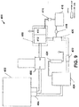
- the liquid inlet 12 is arranged to accept water to be ozonated into the system.
- the liquid inlet 12 accepting water into the system accepts liquid directly into the ozonation flow path.
- the liquid inlet 12 continuously accepts the water as long as ozonated water is being produced. Water flows at a desired flow rate into venturi 14. Ozone gas provided by an ozone generator 16 is mixed with the water in venturi 14.
- the ozone-water mixture flows into gas-liquid separator 18, which separates the gas-liquid mixture into degassed ozonated water and separated ozone gas.
- the separated ozone gas is destroyed in ozone destructor 20 and oxygen gas is vented to the atmosphere.
- Degassed ozonated water is provided to liquid outlet 22 by the gas-liquid separator 18.
- Liquid outlet 22 dispenses ozonated liquid at the desired flow rate (e.g. for use by an end user).
- the flow rate out of the liquid outlet 22 is the same as the flow into the liquid inlet 12 since the flow in is directly dependent on the flow out and any liquid accepted by the system must displace liquid within the system. It is appreciated that in a system having a tank, the flow in is not directly dependent on the flow out and liquid could be dispensed from the tank even if no liquid was flowing into the system.
- Ozonation systems according to embodiments of the present application can also have the dispensing pressure be substantially equal to accepted pressure.
- substantially equal pressure is to be understood to mean that the dispensing pressure is about 4.1 bar (60 psi) less than the accepted pressure, and in particular embodiments is about 2.8 bar (40 psi), about 2.1 bar (30 psi), about 1.4 bar (20 psi) or 0.7 bar (10 psi) less than the accepted pressure.
- Ozonation systems according to the present application can also have the dispensing flow rate be substantially equal to the accepted flow rate.
- the system can have a dosing system to add an additive to the accepted liquid, resulting in an dispensing flow rate that is larger than the accepted flow rate.
- the system can have a leak or other liquid outlet in advance of the dispensing liquid outlet, resulting in an dispensing flow rate that is less than the accepted flow rate.
- Substantially equal flow rate is to be understood to mean that the dispensing flow rate is between about 80% and 120% of the accepted flow rate, and in particular embodiments is between about 90% and about 110%, about 95% and about 105%, or about 99% and about 101% of the accepted flow rate.
- Liquid-Gas Mixer can have a liquid-gas mixer for mixing the ozone and the liquid.
- the liquid-gas mixer is venturi 14.
- the liquid-gas mixer 14 is in fluid communication with the liquid inlet 12 and is arranged to dissolve ozone gas in the liquid to produce the ozonated liquid.
- Liquid-gas mixers are well known in the art, and include such mixers as venturi mixers. Briefly, a venturi mixer is a tube with a constricted flow path, which causes an increase in flow velocity and a corresponding decrease in pressure. The decrease in pressure results in a pressure differential, which draws gas into the liquid.
- Gas-liquid separator Contemplated systems can also have a gas-liquid separator in fluid communication with both the liquid gas-mixer and the liquid outlet.
- the gas-liquid separator shown as element 18 in the embodiment illustrated in Figure 1 , can be arranged to separate undissolved ozone gas from the ozonated liquid.
- the ozonation system includes a gas-liquid separator which can separate ozone from water at high flow rates.
- the gas-liquid separator can comprise a tubular member; a gaseous liquid inlet for entry of the gaseous liquid, the inlet arranged to create a vortex of the gaseous liquid in the gas-liquid separator; a gas outlet arranged to vent the separated gas out of the gas-liquid separator; a separating mixer secured to the tubular member; and a liquid outlet for egress of the degassed liquid from the annular degassed liquid region.
- the separating mixer can comprise an annular separating baffle concentric with the tubular member and arranged to direct the flow of the degassed liquid towards the liquid outlet and to direct the separated gas away from the liquid outlet, the separating baffle and the side wall of the tubular member defining an annular degassed liquid region therebetween.
- the separating mixer can further comprise an annular mixing baffle concentric with the annular separating baffle, the radius of the annular mixing baffle being smaller than the radius of the annular separating baffle.
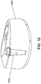
- gas-liquid separators are illustrated in Figure 2 and include gas-liquid inlet 10 for inducing vortex flow 112.
- the gaseous liquid injected via inlet 110 separates into separated gas and degassed liquid.
- the separated gas coalesces into bubbles 114 and is vented out of the gas-liquid separator via gas outlet 116.
- the degassed liquid is dispensed from the gas-liquid separator via degassed liquid outlet 118.
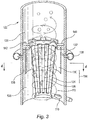
- FIG. 3 illustrates one embodiment of a gas-liquid separator as described herein.
- gaseous liquid enters a tangentially positioned gas-liquid inlet 110, which is positioned in a lower portion 120 of tubular interior chamber 122.
- the gas-liquid inlet 110 induces a vortex flow 112 of gaseous liquid.
- the gaseous liquid is injected at a flow rate sufficient to induce a vortex flow 112 of the gaseous liquid within the interior chamber 122.
- Such a vortex flow 112 has a center of rotation and a low-pressure zone located at the center of rotation.
- the vortex flow 112 has a high-pressure zone around the periphery of the vortex flow 112, for example where the liquid contacts the tubular interior chamber 122.
- the vortex flow 112 of liquid first encounters mixing baffle 124, which creates turbulence in the vortex flow 112 of gaseous liquid, thereby breaking up bubbles and increasing the total surface area of the bubbles. This increase in surface area can enhance the dissolution of the gas into the liquid.
- a mixer therefore, should be understood to be a turbulence enhancer which increases the amount of dissolved gas in the degassed liquid.
- Mixing baffle 124 defines a plurality of apertures 126 for fluid communication between the inner and outer regions defined by the mixing baffle 124.
- the apertures 126 are illustrated as slots extending axially along the central longitudinal axis. The slots can be evenly spaced around the baffle and equally spaced from each other.
- a mixer can also act to direct bubbles of separated ozone gas in to the upper portion of the tubular interior chamber, thereby ensuring that the bubbles are directed to the gas outlet.
- the pressure on a fluid element is a function of the centrifugal force exerted on that fluid element, which is a function of the velocity and the distance from the central longitudinal axis.
- the pressure is, therefore, lowest along the center of rotation (where the centrifugal force is smallest) and the pressure is greatest along the periphery of the vortex (where the centrifugal force is largest).
- the low pressure zone expedites bubbles of undissolved gas coalescing together. Gas separates from the liquid due to the vortex flow 112, coalesces and rises towards the upper portion 128 of the tubular interior chamber 122.
- the vortex flow 112 of gaseous liquid eventually becomes a vortex flow of degassed liquid as the degassed liquid separates from the separated gas.
- the vortex flow 112 of liquid next encounters separating baffle 130, which is positioned in line with degassed liquid outlet 132. It is desirable to prevent bubbles of gas from exiting the gas-liquid separator through the degassed liquid outlet 132.
- bubbles of gas can be swept into the degassed liquid outlet 132 before they coalesce in the low pressure zone.
- devices as described herein have a separating baffle 130 positioned in line with the degassed liquid outlet 132.
- Separating baffle 130 can be positioned to create a thin slit between the side wall and baffle, the thin slit for directing the degassed liquid to the degassed liquid outlet 132 and for trapping bubbles of gas that have not coalesced in the upper portion 128 of the tubular interior chamber 122.
- the separating baffle can be co-axial to the degassed liquid outlet 132.
- Degassed liquid outlet 132 is positioned at the periphery of the vortex, in the high-pressure zone, in order to provide egress for liquid which has been degassed.
- the separating baffle 130 directs separated gas away from the degassed liquid outlet 132 and degassed liquid towards degassed liquid outlet 132.
- the combination of mixing baffle 124 and separating baffle 130 are one embodiment of separating mixer 134. It is to be understood that a separating mixer enhances the turbulence in a fluid, increasing the amount of dissolved gas in the degassed liquid, and directs separated gas away from the liquid outlet while directing the degassed liquid towards the liquid outlet.
- the degassed liquid outlet 132 is positioned above the gas-liquid inlet 110 and below gas outlet (not shown).
- the liquid outlet 132 accepts the degassed fluid from the high-pressure zone and allows the degassed fluid to flow out of the interior chamber 122.
- the degassed liquid outlet 132 is understood to be properly positioned when it is sufficiently far away from both the gaseous liquid inlet 110 and the gas outlet that neither the gaseous liquid nor the separated gas exits via the degassed liquid outlet during conditions of vortex flow. It can also be desirable to position the degassed liquid outlet 132 close to the gaseous liquid inlet 110 and the gas outlet so that the gas-liquid separator does not become overly large. In this manner, the gas-liquid separator can be as small as possible without compromising the effectiveness of the gas-liquid separator.
- the separating baffle 130 and side wall of the interior chamber 122 define a degassed liquid region 136 therebetween.
- the separating baffle 130 is spaced apart from the side wall.
- the degassed liquid region 136 is open at the top and bottom ends, and liquid can flow through the degassed liquid region 136 between the top and bottom ends.
- Figure 3 illustrates the liquid outlet 132 as an annular aperture defined by side walls of the interior chamber 122.
- the liquid outlet 132 leads to collecting outlet 138, which provides a flow of the degassed liquid.
- liquid in the upper portion 128 of the tubular interior chamber 122 has a higher ORP value as it has had a longer contact time with the ozone gas. It is further believed that this liquid can flow into the degassed liquid outlet 132 via the open top end of the degassed liquid region 136 without impediment. In contrast, in a gas-liquid separator having a degassed liquid region with a closed top end, it is believed that liquid in the upper portion 128 of the tubular interior chamber 122 would have to flow into the degassed liquid outlet 132 by first flowing down the center area, against the direction of flow of the remaining liquid.
- One possible arrangement for securing both the mixing baffle 124 and the separating baffle 130 to the side wall is via holder 140, which engages the side wall and the top ends of both the mixing baffle 124 and the separating baffle 122 so that none of the holder 140, mixing baffle 124 and separating baffle 130 disengage from the side wall when the gas-liquid separator is subjected to vortex flow 112.
- Holder 140 and the side wall of the tubular chamber 122 defines apertures 142 through which fluid can flow into or out of the annular degassed liquid region 126 and further defines at least one center opening through which the gaseous liquid and bubbles can flow.
- Holder 140, mixing baffle 136 and separating baffle 122 illustrate one embodiment of a separating mixer 134 secured to the side wall.
- Figure 4 is a view along line 4-4 of Figure 3 .
- Figure 4 shows the annular degassing liquid region 136, the mixing baffle 124 and the apertures 126 defined therein.
- Figures 3 and 4 illustrate the mixing baffle 124 as being positioned concentrically with separating baffle 130 with the separating baffle 130 having a larger radius than the mixing baffle 124. That is to say that the separating baffle and tubular interior chamber share a common longitudinal axis.
- Figures 3 and 4 illustrate the separating baffle 124 and mixing baffle 130 as having a common center, it is to be understood that they would still be “positioned concentrically” as long as the longitudinal axis is shared, even if the mixing baffle 124 is positioned below the separating baffle 130 and they no longer share a common center.
- the degassed liquid outlet 132 can be a substantially annular aperture defined by the side walls of the substantially tubular interior chamber 122. In other embodiments, the degassed liquid outlet 132 can be a plurality of apertures defined by the side walls of the chamber. In yet other embodiments, the degassed liquid outlet can be a tangential outlet in the side wall.
- the separating baffle can be annular in shape and define an annular degassed liquid region (as illustrated by element 136 in Figure 3 ) between the separating baffle 130 and the side wall of the substantially tubular chamber 122.
- the cross-sectional area of the annular degassed liquid region 136 measured as the area between the separating baffle 130 and the side wall when viewed along the longitudinal axis of the interior chamber, can be 1.5x to 2.5x the cross-sectional area of the liquid-gas inlet 110 and/or the degassed liquid outlet 132.
- the separating baffle can be an annular baffle, one or more than one ribs or deflecting guides extending from the side or wall of the substantially tubular chamber, or the like.
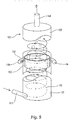
- FIG. 5 Another embodiment of a gas-liquid separator as described herein is illustrated in Figure 5 .
- gaseous liquid enters a tangentially positioned gas-liquid inlet 110, which is positioned in a lower portion 120 of tubular interior chamber 122.
- the gas-liquid inlet 110 induces a vortex flow 112 of gaseous liquid.
- the gaseous liquid is injected at a flow rate sufficient to induce a vortex flow 112 of the gaseous liquid within the interior chamber 122.
- Such a vortex flow 112 has a center of rotation and a low-pressure zone located at the center of rotation.
- the vortex flow 112 has a high-pressure zone around the periphery of the vortex flow 112, for example where the liquid contacts the tubular interior chamber 122.
- degassed liquid region 136 is open at the top and bottom ends, and liquid can flow through the degassed liquid region 136 between the top and bottom ends.
- the separated gas coalesces in the low-pressure zone to form bubbles, which further coalesce, leading to accumulation of the separated gas.
- the coalesced bubbles rise into the upper portion 128 of the interior chamber 122 and exit out of separated gas outlet 144.
- the separated gas outlet 144 allows the gas to escape the interior chamber 122 and is, therefore, positioned in the upper portion 128 of the interior chamber, where the separated gas would accumulate when the gas-liquid separator is use.
- the gas-liquid separator can have a float (not shown) positioned in the interior chamber 122.
- the float When in use, the float is pushed up by the liquid and closes off the separated gas outlet 144. Separated gas accumulates and once sufficient gas collected, the float is displaced and separated gas outlet 144 is opened, allowing the collected gas to escape out of the separated gas outlet 144. Once the separated gas has been vented, the float rises and again close off the separated gas outlet 144. This allows the gas-liquid separator to maintain a relatively constant pressure within the interior chamber 122.
- a mixture of gas and liquid is injected into a gas-liquid separator.
- This mixture of gas and liquid includes bubbles of gas mixed in with the liquid.
- such a mixture is termed a "gaseous liquid”.
- the gaseous liquid is separated into a “degassed liquid” and "separated gas”.
- the gas-liquid separator can promote dissolving the gas into the liquid.
- the gas-liquid separator can promote vaporizing or otherwise adding liquid to the gas. It is, therefore, to be understood that the degassed liquid can have gas dissolved therein, and/or the separated gas can have liquid added thereto.
- degassed liquid is, however, understood to represent liquid substantially lacking bubbles therein, even if the liquid has a gas dissolved therein.
- separated gas is to be understood to be the gas when it has substantially coalesced together, even if the gas has liquid added thereto.
- high flow rate when used in the context of the overall flow capacity of a gas-liquid separator as described herein, would mean a flow rate of greater than four volumes per minute, where one volume is equal to the volume of the gas-liquid separator.
- Gas-liquid separators as described herein, generally operate in a substantially vertical orientation, with a gaseous liquid inlet stream entering a lower portion of the device, separated gas exiting the device via a separated gas outlet in an upper portion of the device, and degassed liquid exiting the device via a degassed liquid outlet positioned between the gas-liquid inlet and the separated gas outlet.
- upper and lower are understood to refer to relative portions of the device when the device is positioned as it would be when it is in use.
- the term “lower portion” refers to the portion of the gas-liquid separator which through in which gaseous liquid and degassed liquid flow.
- the term “upper portion” refers to the portion of the gas-liquid separator in which the separated gas is collected before being vented out of the separator.
- the lower portion is conical or frustoconical with a half angle between about 5 and 7 degrees.
- the gas-liquid inlet 110 can be positioned substantially tangential to the interior chamber 122.
- vortex flow 112 can be induced by methods other than the tangential entry of the gaseous liquid.
- a gaseous liquid inlet can be positioned coaxial to the central longitudinal axis if the inlet includes a flow-deflection component to deflect axially inflowing liquid so that the desired vortex flow is induced.
- a flow-deflection component is a rotation-symmetrical base body element as described in U.S. Patent No. 6,053,967 .
- This flow deflection component includes deflection vanes, which are curved in planes perpendicular relative to the longitudinal axis of the chamber, to direct the axially inflowing water to form the desired vortex flow.
- vortex flow can be induced through mechanical methods, such as by the positioning of a motor-driven paddle in the substantially tubular chamber, where the motor-driven paddle drives vortex flow through physical displacement of the liquid.
- substantially tubular interior chamber is to be understood to mean a chamber that is shaped to encourage, not deter, a vortex flow.
- a chamber that deters a vortex flow may, for example, have a substantially square or rectangular horizontal cross-section since the side walls would discourage the flow of liquid circularly around the interior chamber.
- a chamber that encourages a vortex flow could, for example, have a substantially oval or circular horizontal cross-section since the side wall(s) would direct the flow of liquid around the interior chamber. It is understood, however, that chambers with square or rectangular cross-sections can include other features that encourage vortex flow. In such situations, it is to be understood that the term “substantially tubular interior chamber” would encompass those chambers.
- Ozone gas can be provided to the liquid-gas mixer (e.g. venturi 14 in Figure 1 ) from a number of different sources.
- a corona discharge system can be used to generate and provide the ozone gas.
- a corona discharge system uses an electrode with a high potential and takes oxygen gas and passes a current through the gas so as to ionize the gas and create a plasma around the electrode.
- the ionized gas recombines with oxygen to form ozone.
- the oxygen gas used in a corona discharge system can be oxygen from the air or from another oxygen source, for example the output from an oxygen concentrator.
- Corona discharge systems can use sustained ionization or intermittent ionization to generate ozone.
- Corona discharge typically uses two asymmetric electrodes: a highly curved electrode (e.g. tip of a needle or small diameter wire) and an electrode with a low curvature (e.g. a plate or ground).
- Coronas may be positive or negative, depending on the polarity of the voltage on the highly curved electrode.
- a negative corona discharge system is used. In some embodiments of known corona discharge systems, as much as 10 grams of ozone per hour can be provided.
- Ozone Destructor Systems according to the present application may also include an ozone destruction assembly, or "ozone destructor", as illustrated by element 20 in Figure 1 .
- Ozone destructors are known in the art. Briefly, the ozone destruction assembly can include a gas inlet for accepting ozone gas from the gas-liquid separator 18. Ozone gas can be directed from the gas inlet to a destruction chamber with a catalyst for accelerating the decomposition of ozone into oxygen. The decomposition can be further accelerated by heating the destruction chamber and/or the ozone gas to be destroyed to an elevated temperature.
- the catalyst is manganese dioxide or activated carbon. The resulting oxygen gas produced from the destruction of the ozone gas can be discharged to the atmosphere via an oxygen outlet.
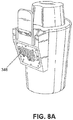
- Scrubber/Extractor The system for providing ozonated liquid according to the present application can be adapted or retrofitted to a mobile floor scrubber or extractor.
- Scrubbers and extractors are floor cleaners which eject a cleaning solution from a reservoir of clean liquid onto the floor and then remove the solution by vacuuming it into a reservoir of dirty liquid. Scrubbers and extractors are typically used in hospitals, hotels or other commercial or industrial settings.
- the contemplated system takes water from the clean reservoir as the liquid to be ozonated, passes the water through the ozonation flow path, and ejects the ozonated water as the cleaning solution. Used ozonated water vacuumed from the floor is then stored in a dirty reservoir until the scrubber or extractor is emptied.
- the scrubber 210 has a clean reservoir 212 holding water to be ozonated 214.
- the water to be ozonated 214 passes through inlet 216 in order to enter the ozonation flow path.
- the water flows at a desired flow rate through venturi 218.
- Venturi 218 mixes the water with ozone produced in ozone generator 220 to provide an ozone-water mixture, which flows through gas-liquid separator 222.
- the gas-liquid separator 222 separates the mixture into gaseous ozone and ozonated water.
- the gaseous ozone passes through ozone destructor 224 before being vented as oxygen.
- the ozonated water passes through outlet 226 as it leaves the ozonation flow path to be used by the scrubber as the cleaning solution.
- the scrubber 210 can include scrubbing brushes 228 which use the ozonated water to scrub the floor, resulting in dirty ozonated water.
- the dirty ozonated water 230 is sucked into dirty reservoir 232 via vacuum inlet 234.
- the system can be adapted to interface with a commercially available scrubber or extractor.
- a system according to the present application can be installed downstream from the clean reservoir and upstream from the scrubbing brushes. Installing the system in a hose connecting the clean reservoir and scrubbing brushes allows the system to provide ozonated water on demand.
- the liquid accepted by the ozonation flow path is substantially unozonated.
- “Substantially unozonated” is to be understood to mean that the accepted liquid does not exceed a threshold value.
- the threshold value can be an ORP value of about 250 millivolts (mV), preferably about 150 and more preferably about 50 mV. It is appreciated that the threshold value can alternatively be measured in ppm of dissolved ozone, and the threshold value can be about 0.1, preferably about 0.05, more preferably about 0.02 and even more preferably about 0.01 ppm of dissolved ozone.
- an ozonation flow path can take an accepted liquid having 0 ppm dissolved ozone and an ORP of 0 mV and, passing the fluid through the ozonation flow path only once, dispense an ozonated liquid having at least about 8 ppm ozone and/or an ORP due to the dissolved ozone of at least about 900 mV.
- a similar final amount of dissolved ozone and/or a final ORP value can be observed in the dispensed ozonated liquid when the accepted liquid already has a non-zero amount of dissolved ozone and/or a non-zero ORP.
- ozonated liquid can generally refer to liquid with any amount of ozone dissolved therein.
- the term "ozonated liquid” is to be understood to be liquid that has sufficient ozone dissolved therein that the oxidation-reduction potential (ORP), solely due to the dissolved ozone, is at least about 450 mV.
- the ORP solely due to the dissolved ozone is at least about 600, 750, 800, 850, 900, 950, 1000, 1050, 1100 or 1150 mV.
- an alternative definition for "ozonated liquid” according to another embodiment is a liquid that has sufficient ozone dissolved therein to reach a concentration of least 3 parts per million (ppm), and preferably at least 4, 5, 6, 7, 8, 9 or 10 ppm.
- Oxidation-reduction potential is a measure of disinfectant levels in water systems, independent of the oxidant (e.g. ozone, chlorine, peroxide, peroxyacetic acid). It is generally accepted that liquids with ORP values of 650 to 700 mV kill bacteria within a few seconds. Yeast and other fungi can be killed with such a liquid upon contact for a few minutes. Liquids with an ORP value of 450 mV are termed "sanitizing liquids”. Liquids with an ORP value of 600 mV are termed “disinfecting liquids”. Liquids with an ORP value of 800 mV are termed "sterilizing liquids”.
- ORP value "due solely to dissolved ozone” is to be understood to mean that the ORP is a measure of the oxidation potential of the dissolved ozone and does not take into account the oxidation and/or reduction potential of other additional components of the liquid. For example, chlorine dissolved in water has an oxidation potential. Adding ozone to the chlorinated water would increase the ORP.
- the ORP value "due solely to dissolved ozone” corresponds to the ORP value of the water if it was not chlorinated, regardless of the ORP value of the ozonated and chlorinated water.
- ozonation systems having a recirculating ozonation flow path only dissolve a small amount of ozone every time the liquid travels through the recirculating flow path. Repeatedly recirculating the liquid adds a small amount of ozone every time the liquid is recirculated, eventually resulting in a larger amount of dissolved ozone and higher ORP value.
- Ozonation systems according to the present application can be connected to a municipal water supply. Typical municipal water supplies provide water at a pressure between approximately 1.4 bar (20 psi) and approximately 4.1 bar (60 psi).
- An ozonation system according to the present application accepts water from the municipal water supply or from another water source (for example from a pressurized holding tank). In some instances, for example if water is accepted from a pressurized tank, water may be provided at pressures as high as 5.5 or 6.9 bar (80 or 100 psi).
- the accepted water enters the liquid inlet 12 at the desired flow rate and accepted pressure and travels through the ozonation flow path, which does not include any pressure regulation systems, for example pressure reducing valves or pressure pumps.
- the ozonated water dispensed from the system has a dispensing pressure that is directly dependent on the accepted pressure.
- the accepted water flows into the liquid inlet of the ozonation flow at a desired flow rate, which is a function of the water pressure and cross-sectional area of the liquid inlet.
- the desired flow rate typically ranges from 3 to 10 liters per minute, but can be as high as about 38 liters per minute.
- the accepted water enters the liquid inlet 12 at the desired flow rate and accepted pressure and travels through the ozonation flow path.
- the flow rate of the ozonated water dispensed from the system is the same as the flow rate accepted by the system.
- a system with a “holding tank” is to be understood to be a system with a reservoir, for example a vessel, tank, pipe, pool, drum or any other container, for storing, accumulating or saving liquid until it is needed.
- a systems that is "holding tank-less” is to be understood to be a system that does not store, accumulate or save liquid until it is needed. In such a holding tank-less system, liquid would be accepted into the system, flow through the flow path, and be dispensed from the system without being placed in a reservoir.
- the overall volume of the system is small in comparison to the flow rate of dispensed ozonated liquid.
- the ratio between volume and flow rate is understood to be a measure of the average fluid residence time of the liquid in the ozonation flow path.
- the fluid residence time of a system is an expression of how long it takes a fluid element to move through a volume which is in equilibrium. It is to be understood that fluid residence time is a measure of the residence time of the liquid in that volume. It is the average time a fluid element spends within a specified region of space, such as a reservoir. In a well-mixed system with all fluid elements in equilibrium, residence time can be calculated by dividing the volume in question by the volumetric flow rate of the liquid.
- Embodiments of the present application have an average fluid residence time of the liquid in the ozonation flow path of less than about 5 minutes. In other particular embodiments, the average fluid residence time is less than about 1, about 0.7 or about 0.05 minutes.
- the ozonation system has a liquid inlet and a liquid outlet, with the ozonation flow path therebetween.
- the ozonation system according to the present application includes ozonation flow path with a liquid inlet and liquid outlet.
- the liquid inlet can correspond to the nozzle which accepts liquid into the ozonation system and the fluid residence time is measured from the nozzle to the liquid outlet which dispenses ozonated liquid from the ozonation system.
- the liquid inlet corresponds to the liquid-gas mixer and the fluid residence time is measured from the liquid-gas mixer to the liquid outlet which dispenses ozonated liquid from the ozonation system.
- a venturi mixer is joined to a gas-liquid separator by 76 mm (3") of 9.5 mm (3/8") tubing.
- the average residence time between the venturi mixer and the gas-liquid separator is in the range of about 0.01 and about 0.1 seconds.
- the average residence time in the ozonation flow path can be less than about 0.7 or less than about 0.05 minutes, depending on the flow rate of the liquid.
- water ozonation devices can optionally use a removable filter cartridge when the ozonation device includes an ozone source such as, for example, a corona discharge system.
- the removable filter cartridge can be used to increase the concentration of ozone generated by the corona discharge system by reducing the amount of moisture in the provided air and/or increasing the concentration of oxygen (for example by removing nitrogen) in the air provided to the corona discharge system.
- the cartridge can be arranged for integration and use with first and second ozonation devices, and can include a usage counter to increment a usage count in response to a received signal from an ozonation device, and a device interface to provide an expiry indication when the cartridge is no longer suitable for use.
- the devices count usage can be based on different first and second cycle count conditions.
- the same cartridge can be used in different devices, such as, for example, a consumer water ozonation device (such as described in U.S. Patent No. 6,964,739 ), a high capacity commercial water ozonation device, a large volume ozone sprayer, a holding tank-less water ozonation device, etc.
- the devices can include logic to disable usage of the system after the cartridge has reached a predetermined usage condition. Compatibility identifiers can be used in the cartridge and devices to restrict use of the cartridge with certain devices.
- the present application provides a cartridge-enhanced water treatment system including a cartridge and first and second ozonation devices.
- the first and second ozonation devices can be the same or different.
- the first and second ozonation devices can be first and second holding tank-less ozonation devices; or the first ozonation device can be a holding tank-less ozonation device and the second ozonation device can be a residential ozonation device (such as described in United States Patent Application Publication No. US-2008-0190825-A1 ).
- the first ozonation device is of a first type, and includes a first device cycle count manager configured to signal the cartridge upon completion of an ozonation cycle of the first ozonation device with respect to a first ozonation device cycle count condition.
- the second ozonation device is of a second type, the second type being different from the first type.
- the second ozonation device includes a second device cycle count manager configured to signal the cartridge upon completion of an ozonation cycle of the second ozonation device with respect to a second ozonation device cycle count condition.
- the cartridge is a desiccant cartridge, is arranged for integration and independent use with both the first ozonation device and the second ozonation device, and includes: an air inlet to receive atmospheric air, a desiccant material to remove moisture, and a dry air outlet for interfacing with one of the first and second ozonation devices to provide dry air to an ozone generator.
- the cartridge is a nitrogen-removing cartridge, is arranged for integration and independent use with both the first ozonation device and the second ozonation device, and includes: an air inlet to receive atmospheric air, a material to remove nitrogen gas from the air so as to increase the concentration of oxygen in the air, and an oxygen-enriched air outlet for interfacing with one of the first and second ozonation devices to provide oxygen-enriched air to an ozone generator.
- the cartridge is both a nitrogen-removing and desiccant cartridge, and includes both a desiccant material to remove moisture and a material to remove nitrogen gas from the received air.
- the cartridge further includes a usage counter arranged to modify a stored usage count in response to receipt of a signal from the first or second cycle count manager, and a device interface arranged to provide an expiry indication indicating that the cartridge is no longer suitable for further use, based on the stored usage count.
- the cartridge can optionally include a chronological counter arranged to modify a stored time count.
- the device interface in such a cartridge can provide an expiry indication based on the stored usage count or the stored time count.
- the cartridge could be stored in a vacuum packed container and, once the container is opened and the cartridge exposed to atmospheric air, the chronological counter could be started by the removal of a tab. Removal of the tab could, for example, engage a battery with dedicated circuitry for modifying the stored time count.
- the first and/or second cycle count managers can comprise a cycle memory arranged to keep track of partially completed cycles.
- the cartridge includes a cartridge compatibility identifier
- the first and second ozonation devices include first and second device compatibility identifiers, respectively.
- First and second device compatibility managers are arranged to determine whether the cartridge is compatible with the first or second ozonation device, respectively, based on a comparison of the cartridge compatibility identifier with the first and second device compatibility identifiers, respectively.
- the first and second device compatibility managers can determine that the cartridge is compatible with the first or second ozonation device when the cartridge compatibility identifier is the same as the first or second ozonation device compatibility identifier, respectively. Therefore, in an example, if the cartridge is compatible with the first and second ozonation devices, all three have the same compatibility identifier.
- the first and second device compatibility managers can determine that the cartridge is compatible with the first or second ozonation device when the first or second ozonation device compatibility identifier identifies a device class with which the cartridge compatibility identifier is compatible.
- the cartridge can then be compatible with a plurality of types of ozonation device of the identified device class.
- the usage counter (with the optional chronological counter) in the cartridge can be reset in response to receipt of a usage and/or chronological counter reset signal.
- the system can further include a usage counter reset manager (with an optional chronological counter reset manager), in communication with the cartridge, arranged to send a usage and/or chronological counter reset signal to reset the usage and/or chronological counter in the cartridge.
- the usage counter reset manager and/or chronological counter reset manager can be arranged to determine an expected life of a dried desiccant material and/or a nitrogen-removing material prior to sending the usage and/or chronological counter reset signal.
- the usage and/or chronological counter reset managers can be arranged to provide a modified value with which the usage and/or chronological counters can be reset, the modified value being based on measured properties of the desiccant material and/or the nitrogen-removing material.
- the present invention provides a cartridge arranged for integration and use with first and second ozonation devices of different types, and including: an air inlet to receive atmospheric air; a desiccant and/or nitrogen removing material to remove moisture and/or nitrogen; an air outlet for interfacing with one of the first and second ozonation devices to provide dry and/or oxygen enriched air to an ozone generator; and a usage and/or chronological counter.
- the usage counter (with an optional chronological counter) is arranged to modify a stored usage count in response to receipt of a first cycle completion signal received from the first ozonation device representing completion of an ozonation cycle with respect to a first ozonation device cycle count condition.
- the usage counter is also arranged to modify the stored usage count in response to receipt of a second cycle completion signal received from the second ozonation device representing completion of an ozonation cycle with respect to a second ozonation device cycle count condition.
- the cartridge also includes a device interface arranged to provide an expiry indication indicating that the cartridge is no longer suitable for further use based on the stored usage count.
- the chronological counter is arranged to modify a stored time count. The device interface in such a cartridge can provide an expiry indication based on the stored usage count or the stored time count.
- the cartridge could be stored in a vacuum packed container and, once the container is opened and the cartridge exposed to atmospheric air, the chronological counter could be started by the removal of a tab. Removal of the tab could, for example, engage a battery with dedicated circuitry for modifying the stored time count.
- Fig. 7 is a block diagram of a cartridge-enhanced water treatment system 300 including a first ozonation device 310, a second ozonation device 320 and a cartridge 330.
- the first ozonation device 310 includes a cycle count manager 312, and optionally includes a compatibility identifier 314, and a compatibility manager 316.
- the cycle count manager 312 is configured to signal the cartridge 330 upon completion of an ozonation cycle of the first ozonation device 310.
- the cycle count manager 312 is particularly configured with respect to a first ozonation device cycle count condition, such as a cycle count threshold.
- a first ozonation device cycle count condition such as a cycle count threshold.
- the cycle count manager 312 can be configured to signal the cartridge 330 after 45 seconds of operation.
- the first ozonation device cycle count condition, or threshold is 45 seconds of operation.
- the cycle count manager 312 can include a cycle memory, to keep track of partially completed cycles. For example, suppose an ozonation device has a cycle count threshold of 45 seconds. If the ozonation device runs for 30 seconds and the device is stopped, the cycle count manager memory will store the partially completed cycle information. When the ozonation device next starts, it calculates after 15 seconds of operation that a cycle has been completed, based on the partially completed cycle information.
- the cycle count manager 312 maintains the cycle memory value when the cartridge is removed from a first ozonation device of a first type and is installed in a second ozonation device of the same type. For example, if the two ozonation devices use the same ozonation device cycle count condition, the cycle memory value is maintained. If the cartridge is subsequently installed on an ozonation device of a different type, or which uses a different ozonation device cycle count condition, the cycle memory can be converted based on a relationship between the two conditions, or can be cleared if such conversion cannot be completed.
- the compatibility identifier 314 is an identifier that can be used within a cartridge-enhanced water treatment system to identify compatible cartridges and water ozonation devices.
- the identifier 314 can also be referred to as a first device compatibility identifier.
- the compatibility manager 316 determines whether a cartridge is compatible with the first ozonation device based on stored compatibility identifiers.
- the compatibility manager 316 can determine that the cartridge is compatible if it has the same compatibility identifier as the first ozonation device. Alternatively, a positive determination can be made if the cartridge and device compatibility identifiers have another predetermined relationship with each other, for example are the opposite of each other.
- the second ozonation device 320 also includes a cycle count manager 322, and optionally a compatibility identifier 324 and compatibility manager 326, which are similar to the above-described cycle count manager 112, compatibility identifier 314, and compatibility manager 316.
- the cycle count manager 322 is configured to signal the cartridge 330 upon completion of an ozonation cycle of the second ozonation device 320.
- the cycle count manager 322 is particularly configured with respect to a second ozonation device cycle count condition.
- the second ozonation device 320 is a low capacity commercial ozonation device capable of performing two or more different ozonation cycles, associated with different types of container or attachment used.
- the second ozonation device cycle count condition can then be different depending on the selected ozonation cycle.
- a second ozonation device cycle count condition for a vegetable bowl cycle can include achieving a desired ozone concentration in the water during a running time of about 3 to 4 minutes.
- the second ozonation device cycle count condition can be dependent on a detection of an ozone concentration in the water, as compared to a desired ozone concentration for a particular cycle, and optionally within an operation time window.
- the cycle count manager 326 can be configured to signal the cartridge 330 after meeting one or more conditions to satisfy completion of a second ozonation device cycle.
- first and second ozonation device compatibility identifiers 314 and 324 are the same, then this signifies that a cartridge having that compatibility identifier will work and be compatible with both the first and second ozonation devices 310 and 320.
- the cartridge 330 includes an air inlet 332, an air outlet 334, and houses at least one material 336 to remove moisture and/or nitrogen.
- the cartridge is arranged for integration and use with the first ozonation device with the second ozonation device.
- the air inlet 232 is to receive atmospheric air, and the air outlet 334 is for interfacing with one of the first and second ozonation devices to provide dry and/or oxygen-enriched air to an ozone generator.
- the cartridge 230 includes a usage counter 338, a stored usage threshold 340, and includes a device interface 342.
- the usage counter 338 modifies a stored usage count in response to receipt of a signal from the cycle count manager 316 or 326. The modification of the usage count can include incrementing or decrementing the count, depending on the implementation of the counter.
- the usage counter 338 can be implemented in a flash memory, or other computer-readable memory or computer-readable medium.
- the usage threshold 340 is stored in a memory in the cartridge 330.
- the cartridge usage threshold 340 can be programmable, so that a manufacturer can program different thresholds for different cartridges.
- the programmability of the cartridge cycle threshold differs from other known cartridges with fixed counts. For instance, certain customers want to change the cartridge after 650 cycles based on their usage conditions and requirements, and others want to change after 800 cycles based on different usage conditions and requirements.
- a commercial ozonation device including a trigger sprayer
- 650 cycles can be run before the cartridge is marked as expired.
- the trigger sprayer sends a signal to the cartridge to remove a cycle every time the system is run.
- the cartridge With a high capacity ozonation device, the cartridge lasts for 4.5 m 3 (1,200 gallons). Typical flow can be about 9.5 L/min (2.5 gallons/minute).
- a cycle can be removed from the cartridge every 45 seconds.
- the cartridge itself receives a signal (in both cases) to remove a cycle from its count. Each system in turn uses different parameters to determine when to send this cycle completion signal.
- the cartridge can provide an expiry indication to the device interface 342, indicating that cartridge is no longer suitable for further use.
- the device interface 342 can provide the expiry indication in a format readable by the ozonation device in which the cartridge is used.
- the expiry indication is a separate indication provided to, and stored in, the device interface 342.
- the usage count begins at the maximum capacity value, and is decremented until it reaches zero.
- the first and second ozonation devices signal the cartridge to decrease, or decrement, the usage count by one upon completion of an ozonation device cycle count condition.
- the providing of a usage count of zero can be an embodiment of providing an expiry indication to the device interface 342.
- the usage counter increments upon cycle completion. If the usage count exceeds the usage threshold, the cartridge can change the usage counter to read "999" or some other value that indicates to the compatibility manager that the cartridge is not to be used.
- the usage counter 338 can be reset, and the desiccant material 336 in the cartridge 330 can be dried, thus permitting re-use and recycling of the cartridge.
- the usage counter 338 can be reset in response to receipt of a usage counter reset signal.
- the usage counter reset signal can be received from an ozonation device with which the cartridge is to be used, or from another specialized device including dedicated circuitry to reset the cartridge.
- the ozonation device or the specialized device can comprise a usage counter reset manager, in electrical communication with the device interface 342 of the cartridge when the cartridge is in use or is in place for usage counter resetting.
- the usage counter reset signal can be issued after a determination has been made that the desiccant material has been sufficiently dried for re-use.
- the usage counter reset manager can determine an expected life of the dried desiccant material.
- the usage counter reset manager can provide a modified value with which the usage counter can be reset, the modified value being based on measured properties of the desiccant material.
- An advantage of providing the usage counter reset manager as part of a specialized device, such as a usage counter resetting apparatus, is to remove the ability of users of the ozonation devices to reset the usage counter.
- an access controller can be provided to restrict access to the usage counter reset manager.
- the access controller can be implemented as any mechanical and/or electrical form of access control, such as a physical key, a security card access control, a biometric identifier, etc.
- the cartridge 330 optionally includes a compatibility identifier 344, also referred to as a cartridge compatibility identifier 344. Based on a comparison between the cartridge compatibility identifier and the first or second ozonation device compatibility identifier, a determination is made whether the cartridge is compatible with the device. For example, if the cartridge compatibility identifier 344 is the same as the first or second compatibility identifiers 314 and 324, then that cartridge is activated or enabled for use with the first or second ozonation devices, respectively.
- the compatibility identifiers 314, 324 and 344 can each be stored as a line of code in a memory provided in the first and second ozonation devices 310 and 320, and the cartridge 330, respectively. If the stored cartridge and device compatibility identifiers correspond, or are the same, then the water ozonation device permits use of the cartridge in the device. This permits a manufacturer to identify or encode cartridges for use only with apparatuses produced by a particular distributor or for a particular reseller. The cartridge can be used with water ozonation devices of different types, for example low capacity and high capacity commercial devices, as long as the devices have the same identifier as the cartridge.
- Embodiments have been described herein with respect to different types of commercial ozonation devices and systems.
- Such commercial devices can include a commercial floor scrubber, or a carpet extractor, equipped with a liquid ozonation device as described herein.
- the features described herein can be incorporated in other classes of ozonation devices or systems, such as industrial or consumer ozonation devices.
- the compatibility identifier can be used to ensure that a cartridge is compatible only with different types of ozonation devices of the same class.
- a consumer compatibility identifier, commercial compatibility identifier, or industrial compatibility identifier can be included in cartridges to be used with one of those classes of ozonation devices having the same, or a corresponding, compatibility identifier.
- the cartridge-enhanced water treatment system 300 can include logic to disable usage of an ozonation device after the cartridge has reached a predetermined usage and/or chronological condition or threshold. This condition may be different depending on the type of ozonation device in which the cartridge is used.
- the logic can be provided in the first and second ozonation devices 310 and 320, and/or in the cartridge 330.
- a base unit of the ozonation device can read the cartridge identifier and check to make sure that the code matches what has been preprogrammed on the control board in the base unit, or otherwise results in a positive compatibility determination. If it does not, then the unit will not run.
- a similar methodology can apply with respect to reading the usage and/or chronological count, and not permitting the device to operate when the usage or chronological count exceeds the programmed threshold.
- Fig. 8A is a front right perspective view of a cartridge according to an embodiment of the present application.
- the usage counter 338, the usage threshold 340, and the optional compatibility identifier 344 are in electrical communication with the device interface 342, such as wired communication, wireless communication, or infrared (IR) communication.
- the device interface 342 such as wired communication, wireless communication, or infrared (IR) communication.
- one, some, or all of the usage counter 338, the usage threshold 340, the optional compatibility identifier 342, and the device interface 344 can all be provided in a printed circuit 346 provided on an outer surface of the cartridge, which mates with the ozonation device.
- Fig. 8B shows an exploded view of a cartridge according to an embodiment of the present application.
- the printed circuit 346 can include the features noted above with respect to the embodiment of Fig. 8A and the cartridge can be disassembled and the desiccant material, the nitrogen removing material and/or the battery for powering the printed circuit 346 can be replaced.
- Fig. 9 is a mechanical system diagram of an exemplary water sanitization system with which a cartridge according to an embodiment of the present application can be used.
- the system illustrated in Fig. 9 shows both water and air paths, and illustrates a filter that can perform air dryer and water filtration. This system is described herein for illustration, as a background for understanding the operational environments of the present application.
- Another exemplary water sanitization system with which a cartridge according to an embodiment of the present application could be used is the system illustrated in Fig. 1 , where the cartridge can be used with ozone generator 16.
- Ozone generator 16 of Fig. 1 and ozone generator 416 of Fig. 9 discussed below, can be used interchangeably.
- a reservoir 402 is provided for containing water that is to be, or is being, sanitized/purified.
- the reservoir 402 is a removable water container. Examples of such containers are discussed in commonly assigned International Patent Application No. WO 2004/113232, published on December 29, 2004 , which is incorporated herein by reference.
- a fluid transfer port or valve 404 is provided at the interface of the reservoir 402 with a base unit incorporating the other elements of the system according to an embodiment of the present invention.
- the fluid transfer valve 404, or fluid control port or liquid interface allows the control of fluids, and in particular, but not limited to, the control of fluids into and out of the container, which allows the container to be removed without leaking.
- the flow into and out of the container may occur simultaneously or sequentially.
- water is taken from the reservoir 402, processed, and pumped back to the reservoir. This is preferably done in such a way that the fluid level in the reservoir is maintained during processing (i.e. the fluid is not drained from the reservoir, processed and then pumped back into the reservoir).
- the fluid transfer valve 404 can be implemented in any number of ways, such as by way of separate check valves for inflow and outflow, or a single double check valve (DCV) for both inflow and outflow.
- DCV single double check valve
- a DCV cap (not shown in the figures) can be provided at the fluid transfer valve when it is implemented as a double check valve.
- An angled section of the DCV cap can preferably be removed to allow the water entering the reservoir from the base unit to be less impeded and therefore faster moving. This faster moving water causes greater mixing in the reservoir and means the dissolved ozone level gets up higher and faster in the reservoir.
- a pump motor 406 provided after the reservoir 402 to draw water from the reservoir.
- the electronics are typically connected to the motor portion, but the pump and motor are interconnected.
- a replaceable cartridge 408, which is removable and preferably disposable, is provided.
- the cartridge 408 can include an air dryer 410 for function in the airflow path, or air line, of the system and/or a water filter 412 for function in the water flow path, or water line, of the system.
- air typically is drawn in from the atmosphere via the air dryer 410, and can then pass through an inlet valve 414, an ozone generator 416, an outlet valve 418, and an ozone contacting device, or mixing device, 420, such as a venturi.
- the inlet and outlet valves 414 and 418 are optional components of the system and can be implemented as check valves. They serve to improve performance of the system, and particularly the ozone generator 416.
- the valves 414 and 418 co-operate to ensure that when the unit is not running, little or no residual ozone gas can diffuse out of the system to atmosphere. Some governmental safety guidelines and regulations include a virtual no ozone gas emissions requirement.
- the valves 414 and 418 assist in achieving such requirements.
- the outlet valve 418 prevents water from backing up into the ozone generator 416 via the ozone contacting device 420 when the unit is at rest with a reservoir, or attachment, on it.
- the ozone generator 416 which can be a corona-discharge type, converts a portion of the oxygen in the air (drawn from the atmosphere) into ozone.
- the ozone is mixed with the water in the ozone contacting device 420.
- the water ozone mixture then preferably passes through an ozone gas atomizer 422 before passing into an off-gas unit 424, which removes the air and undissolved ozone.
- the removed gas is directed to an ozone destructor 426, which converts ozone into oxygen and safely releases it into the atmosphere.
- the ozone gas atomizer 422 is provided downstream of the ozone contacting device 420 and just before the inlet port of the off-gas unit 424 in order to increase the contact time between the micro bubbles of ozone gas and the water.
- the geometry of a preferably necked down inlet port of the off-gas and the cyclonic action of the gas/liquid mixture in the off-gas unit 424 makes the off-gas unit 424 also act as a mixing device. This feature can significantly increase the dissolved ozone level in the water.
- An accumulator (not shown in the figures) can preferably be provided at the top of the off-gas unit 424 that captures excess water that escapes out of the off-gas unit 424 via the gas line.
- This accumulator can drain the excess water back into the off-gas unit 424 when the unit is at rest. Having this accumulator prevents water from getting into ozone destructor 426 when the unit is inverted. If the ozone destructor 426 (such as provided by CARULITE®) gets wet, it is rendered ineffective at destroying ozone gas.
- a sealing check valve (not shown in the figures) can preferably be provided between the off-gas unit 424 and the ozone destructor 426.
- This sealing check valve seals the system from atmosphere in such a way that when the unit is inverted in an attempt to drain water out of it, water is prevented from leaving the system. It is the same principle as inserting a straw in a drink, covering the end of the straw and then removing the straw - the drink stays trapped in the straw. This is advantageous in a unit according to an embodiment of the present invention as it can keep all components wet and the pump primed.
- embodiments of the present application include a removable filter cartridge provided in a base unit of a water sanitization system.
- the removable filter cartridge 408 can include an air dryer 410 and optionally a water filter 412.
- the removable filter cartridge 408 can include a nitrogen remover and optionally a water filter 412.
- the removable filter cartridge 408 can include both an air dryer 410 and a nitrogen remover, and can optionally include a water filter 412.
- the present invention takes advantage of the fact that dry air and/or oxygen-enriched air reacts better in an ozone generator, yielding better ozone concentration output, which in turn results in a better "kill rate" with respect to bacteria when ozonated water is applied to food, items or surfaces.
- the removable filter cartridge includes an air dryer 410 and does not include a water filter.
- the air dryer 410 comprises a desiccant material that removes moisture from air.
- the air dryer 410 can be placed anywhere in the base unit as long as it is before the ozone generator 416 and the ozone contacting device 420 with respect to air flow.
- the ozone contacting device 420 draws air from the atmosphere into the air dryer 410 and then into the ozone generator 416. Dry air can achieve much higher concentrations of ozone gas than humid air in a corona discharge ozone generator. As such, embodiments of the present invention provide a significant increase to the concentration of dissolved ozone in the water. An examination of experimental test results shows an increase in ozone concentration from approximately 1 ppm without the air dryer to over 3.5 ppm with the air dryer.
- a cartridge according to the present application could also be used in a non-recirculation system.
- a fluid is transported from a fluid source to an ozone contacting device and then discharged as a sanitizing ozonated fluid.
- an ozone generator which provides ozone to the ozone contacting device, yields better ozone concentration output from dry and/or oxygen enriched air, it may be beneficial to use a cartridge according to the present application to dry and/or remove nitrogen from the air used by the ozone generator.
- Fig. 10 is a back perspective view of a removable air dryer cartridge 430 installed in a base unit 440 of a water ozonation device according to an embodiment of the present invention.
- the removable air dyer cartridge 430 is a particular embodiment of the removable cartridge 408 having an air dryer and no water filter, and also having features specific to its use and interconnection with a base unit.
- Embodiments described herein can be represented as a software product stored in a machine-readable medium (also referred to as a computer-readable medium, a processor-readable medium, or a computer usable medium having a computer-readable program code embodied therein).
- the machine-readable medium can be any suitable tangible medium, including magnetic, optical, or electrical storage medium including a diskette, compact disk read only memory (CD-ROM), memory device (volatile or non-volatile), or similar storage mechanism.
- the machine-readable medium can contain various sets of instructions, code sequences, configuration information, or other data, which, when executed, cause a processor to perform steps in a method according to an embodiment described herein.
- Those of ordinary skill in the art will appreciate that other instructions and operations necessary to implement the described embodiments can also be stored on the machine-readable medium.
- Software running from the machine-readable medium can interface with circuitry to perform the described tasks.
Claims (7)
- Cartouche (330) agencée pour être intégrée et utilisée avec des premier (310) et second (320) dispositifs d'ozonation de différents types, la cartouche (330) comprenant :une entrée d'air (332) pour recevoir l'air atmosphérique ;un matériau desséchant et/ou d'élimination de l'azote (336) pour éliminer l'humidité et/ou l'azote de l'air atmosphérique reçu ;une sortie d'air (334) pour s'interfacer avec l'un des premier (310) et second (320) types de dispositifs d'ozonation afin de fournir de l'air sec et/ou enrichi en oxygène à un générateur d'ozone ;un compteur d'utilisation (338) comprenant un processeur, le processeur servant à :modifier un compte d'utilisation stocké, en réponse à la réception d'un premier signal d'achèvement de cycle reçu en provenance d'un premier gestionnaire de compte de cycle (312) du premier dispositif d'ozonation (310), etmodifier le compte d'utilisation stocké en réponse à la réception d'un second signal d'achèvement de cycle reçu en provenance d'un second gestionnaire de compte de cycle (322) du second dispositif d'ozonation (320) ; etune interface de dispositif (342) agencée pour fournir une indication d'expiration indiquant que la cartouche (330) n'est plus appropriée pour une utilisation ultérieure sur la base du compte d'utilisation stocké.
- Procédé d'élimination de l'humidité de l'air atmosphérique à l'aide d'une cartouche (330) selon la revendication 1, le procédé comprenant :la réception d'air atmosphérique en provenance d'une entrée d'air (332) ;la mise en contact du matériau desséchant (336) avec l'air atmosphérique reçu pour éliminer l'humidité et/ou l'azote de l'air atmosphérique reçu ;la fourniture de l'air sec à un générateur d'ozone par l'intermédiaire d'une sortie d'air sec (334) ;au niveau d'un compteur d'utilisation (338) servant à modifier un compte d'utilisation stocké :la modification du compte d'utilisation stocké en réponse à un premier signal d'achèvement de cycle reçu en provenance d'un premier gestionnaire de compte de cycle (312) du premier type de dispositif d'ozonation (310), oula modification du compte d'utilisation stocké en réponse à un second signal d'achèvement de cycle reçu en provenance d'un second gestionnaire de compte de cycle (322) du second type de dispositif d'ozonation (320) ; etla fourniture d'une indication d'expiration lorsque la cartouche (330) n'est plus appropriée pour une utilisation ultérieure sur la base du compte d'utilisation stocké.
- Procédé selon la revendication 2, lesdits premier (312) et second (322) gestionnaires de compte de cycles comprenant chacun une mémoire de cycle, et ledit procédé comprenant en outre le suivi de cycles partiellement terminés à l'aide de la mémoire de cycle.
- Procédé selon la revendication 2, comprenant en outre la réinitialisation du compteur d'utilisation (338) en réponse à la réception d'un signal de réinitialisation de compteur d'utilisation.
- Procédé selon la revendication 4, comprenant en outre l'envoi du signal de réinitialisation du compteur d'utilisation par un gestionnaire de réinitialisation de compteur d'utilisation en communication avec la cartouche (330).
- Procédé selon la revendication 5, comprenant en outre la détermination, au niveau du gestionnaire de réinitialisation de compteur d'utilisation, d'une durée de vie attendue d'un matériau desséchant sec (336) avant d'envoyer le signal de réinitialisation du compteur d'utilisation.
- Procédé selon la revendication 6, comprenant en outre la fourniture d'une valeur modifiée avec laquelle le compteur d'utilisation (338) peut être réinitialisé, la valeur modifiée étant basée sur les propriétés mesurées du matériau desséchant (336) et étant fournie par le gestionnaire de réinitialisation de compteur d'utilisation.
Applications Claiming Priority (5)
| Application Number | Priority Date | Filing Date | Title |
|---|---|---|---|
| US24810209P | 2009-10-02 | 2009-10-02 | |
| US24805509P | 2009-10-02 | 2009-10-02 | |
| US24807509P | 2009-10-02 | 2009-10-02 | |
| EP10819768.2A EP2482965B1 (fr) | 2009-10-02 | 2010-09-30 | Système de traitement d'eau à l'ozone sans cuve de rétention |
| PCT/CA2010/001520 WO2011038489A1 (fr) | 2009-10-02 | 2010-09-30 | Système de traitement d'eau à l'ozone sans cuve de rétention |
Related Parent Applications (2)
| Application Number | Title | Priority Date | Filing Date |
|---|---|---|---|
| EP10819768.2A Division-Into EP2482965B1 (fr) | 2009-10-02 | 2010-09-30 | Système de traitement d'eau à l'ozone sans cuve de rétention |
| EP10819768.2A Division EP2482965B1 (fr) | 2009-10-02 | 2010-09-30 | Système de traitement d'eau à l'ozone sans cuve de rétention |
Publications (2)
| Publication Number | Publication Date |
|---|---|
| EP3348324A1 EP3348324A1 (fr) | 2018-07-18 |
| EP3348324B1 true EP3348324B1 (fr) | 2020-02-05 |
Family
ID=43825459
Family Applications (2)
| Application Number | Title | Priority Date | Filing Date |
|---|---|---|---|
| EP17192448.3A Active EP3348324B1 (fr) | 2009-10-02 | 2010-09-30 | Cartouche et méthode pour l'élimination de l'humidité de l'air atmosphérique |
| EP10819768.2A Active EP2482965B1 (fr) | 2009-10-02 | 2010-09-30 | Système de traitement d'eau à l'ozone sans cuve de rétention |
Family Applications After (1)
| Application Number | Title | Priority Date | Filing Date |
|---|---|---|---|
| EP10819768.2A Active EP2482965B1 (fr) | 2009-10-02 | 2010-09-30 | Système de traitement d'eau à l'ozone sans cuve de rétention |
Country Status (4)
| Country | Link |
|---|---|
| US (1) | US8894750B2 (fr) |
| EP (2) | EP3348324B1 (fr) |
| HK (1) | HK1251511A1 (fr) |
| WO (1) | WO2011038489A1 (fr) |
Families Citing this family (10)
| Publication number | Priority date | Publication date | Assignee | Title |
|---|---|---|---|---|
| US10005682B1 (en) | 2009-10-02 | 2018-06-26 | Tersano Inc. | Holding tank-less water ozonating system |
| WO2011038489A1 (fr) | 2009-10-02 | 2011-04-07 | Advantage Engineering Inc. | Système de traitement d'eau à l'ozone sans cuve de rétention |
| WO2012058774A1 (fr) | 2010-11-02 | 2012-05-10 | Tersano Inc. | Système d'ozonisation d'eau sans cuve de stockage utilisant la décomposition électrolytique d'eau |
| WO2013025660A1 (fr) * | 2011-08-13 | 2013-02-21 | Eco-Safe Systems Usa, Inc | Système portatif de désinfection à l'ozone |
| US20160251243A1 (en) * | 2015-02-27 | 2016-09-01 | Daniel W. Lynn | Systems and methods for creating an oxidation reduction potential (orp) in water for pathogenic control |
| RU169750U1 (ru) * | 2016-03-30 | 2017-03-31 | Федеральное государственное бюджетное образовательное учреждение высшего образования "Ярославский государственный технический университет" (ФГБОУ ВО "ЯГТУ") | Устройство для контакта газа с жидкостью |
| US10123559B2 (en) * | 2016-07-07 | 2018-11-13 | Guardian Manufacturing, Inc. | Ozone rain pan |
| US10913095B2 (en) | 2016-07-07 | 2021-02-09 | Guardian Manufacturing, Inc. | Ozone rain pan |
| RU174136U1 (ru) * | 2017-05-15 | 2017-10-03 | Федеральное государственное бюджетное образовательное учреждение высшего образования "Ярославский государственный технический университет" ФГБОУВО "ЯГТУ" | Аппарат для контакта газа с жидкостью |
| US11033647B2 (en) | 2017-12-29 | 2021-06-15 | Walker Water, LLC | Apparatus for generating aqueous ozone |
Family Cites Families (60)
| Publication number | Priority date | Publication date | Assignee | Title |
|---|---|---|---|---|
| BE826801A (fr) | 1975-03-18 | 1975-07-16 | Dispositif de sterilisation de l'eau des piscines | |
| US4427426A (en) | 1982-06-28 | 1984-01-24 | Johnson Ronald G | Ozonizer system |
| US4619763A (en) | 1983-07-21 | 1986-10-28 | Brien Edward J O | Ozone H2 O treatment |
| US4752740A (en) | 1986-05-19 | 1988-06-21 | Steininger Jacques M | Electronic water chemistry analysis device with linear bargraph readouts |
| KR920008813Y1 (ko) | 1990-07-09 | 1992-12-19 | 삼성전자 주식회사 | 오존발생장치가 내장된 수도직결식 정수기 |
| JP3080971B2 (ja) | 1990-08-01 | 2000-08-28 | ペルメレック電極株式会社 | オゾン製造用電極構造体及びその製造方法 |
| US5218304A (en) | 1992-03-06 | 1993-06-08 | Monsanto Company | Electronic pH and ORP indicator |
| JP3274880B2 (ja) | 1992-03-09 | 2002-04-15 | ペルメレック電極株式会社 | 電解オゾン発生装置 |
| US5316740A (en) | 1992-03-26 | 1994-05-31 | Los Alamos Technical Associates, Inc. | Electrolytic cell for generating sterilization solutions having increased ozone content |
| US5433866A (en) | 1992-06-15 | 1995-07-18 | Hoppe; Jeffrey E. | System and method for treating water |
| JP2749495B2 (ja) | 1993-03-15 | 1998-05-13 | 長廣 仁蔵 | 高濃度オゾン水製造方法及び高濃度オゾン水製造装置 |
| EP0646380B1 (fr) | 1993-09-01 | 1997-06-25 | Fresenius AG | Séparateur d'air |
| US5520893A (en) * | 1993-09-29 | 1996-05-28 | Oxidyn, Incorporated | Apparatus with safety means for sterilizing articles with ozone |
| WO1996002310A1 (fr) | 1994-07-13 | 1996-02-01 | Mazzei Angelo L | Injection de gaz dans un liquide et elimination des gaz non dissous |
| KR100504412B1 (ko) | 1996-04-02 | 2005-11-08 | 페르메렉덴꾜꾸가부시끼가이샤 | 전해용전극및당해전극을사용하는전해조 |
| US5851407A (en) | 1996-12-04 | 1998-12-22 | Applied Process Technolgy, Inc. | Process and apparatus for oxidation of contaminants in water |
| US5989407A (en) | 1997-03-31 | 1999-11-23 | Lynntech, Inc. | Generation and delivery device for ozone gas and ozone dissolved in water |
| US6287431B1 (en) | 1997-03-21 | 2001-09-11 | Lynntech International, Ltd. | Integrated ozone generator system |
| US6054046A (en) | 1997-04-02 | 2000-04-25 | Nelson; William R. | System for re-circulating a gas mixture to treat liquids |
| US6723233B1 (en) | 1999-09-10 | 2004-04-20 | Ronald L. Barnes | Ozone generator retrofit apparatus for jetted tubs and spas |
| AU3090099A (en) | 1998-03-20 | 1999-10-18 | Angelo L. Mazzei | Stripping of contaminants from water |
| US6123839A (en) | 1998-04-06 | 2000-09-26 | Sussman; Arthur | Automatic fluid dispensing system |
| US6132629A (en) | 1998-10-20 | 2000-10-17 | Roger J. Boley | Method and apparatus for continuous or intermittent supply of ozonated water |
| US6309538B1 (en) | 1998-10-27 | 2001-10-30 | Polaris Pool Systems, Inc. | Spa chemistry monitoring and chemical dispensing unit |
| DE69905766T2 (de) | 1998-12-16 | 2003-09-18 | Lynntech Inc | Vorrichtung zur behandlung von trinkwasser an dem verwendungsort |
| US6299761B1 (en) | 1999-10-13 | 2001-10-09 | Ozonaid International, Inc. | Water purifier system |
| AU2001249521A1 (en) | 2000-03-28 | 2001-10-08 | Del Industries, Inc. | Spray apparatus for providing an ozone/aqueous stream |
| US6491811B2 (en) | 2000-11-22 | 2002-12-10 | Fantom Technologies Inc. | Sensor for a water treatment apparatus |
| US20020060189A1 (en) | 2000-11-22 | 2002-05-23 | Wayne Conrad | Method and apparatus for controlling a household water purifier |
| KR20070091240A (ko) | 2000-12-12 | 2007-09-07 | 테르사노 아이엔씨. | 오존수를 생성하고 적용하기 위한 장치 및 방법 |
| JP4116266B2 (ja) | 2001-05-25 | 2008-07-09 | 株式会社オメガ | 携帯可能な殺菌洗浄水の生成方法と其の装置 |
| US8272582B2 (en) * | 2001-11-26 | 2012-09-25 | Gillette Thomas D | Systems and methods for producing ozonated water on demand |
| US7402253B2 (en) | 2002-04-17 | 2008-07-22 | Nutech 03, Inc. | Controlled bypass flow and ozone proportion method and system |
| US7445721B2 (en) | 2003-12-03 | 2008-11-04 | Idaho Research Foundation, Inc. | Reactive filtration |
| KR20050088156A (ko) | 2003-01-10 | 2005-09-01 | 테르사노 아이엔씨. | 위생처리 시스템 및 오존처리된 액체를 만들어내는 시스템구성요소 |
| US6866703B2 (en) * | 2003-01-28 | 2005-03-15 | Angelo L. Mazzei | Enhanced separation and extraction of gas from a liquid utilizing centrifugal forces |
| US8545682B2 (en) | 2003-05-23 | 2013-10-01 | Enviro Swim Pty Ltd | Swimming pool cleaning and sanitizing system |
| US7767168B2 (en) | 2003-06-26 | 2010-08-03 | Tersano Inc. | Sanitization system and system components |
| WO2004113232A2 (fr) | 2003-06-26 | 2004-12-29 | Tersano Inc. | Systeme et contenants de filtration d'eau et de desinfection d'articles |
| US20060027463A1 (en) | 2004-06-23 | 2006-02-09 | Del Industries, Inc. | Water treatment apparatus utilizing ozonation and electrolytic chlorination |
| EP1778592B1 (fr) | 2004-07-07 | 2013-07-31 | Disney Enterprises, Inc. | Oxydation a commande de processus |
| KR20070107705A (ko) * | 2005-02-21 | 2007-11-07 | 에이지 마츠무라 | 오존수 생성 장치, 오존수 생성 장치에 이용하는 기액 혼합구조, 오존수 생성 방법 및 오존수 |
| EP1866058A4 (fr) * | 2005-03-18 | 2009-05-27 | Tersano Inc | Systeme d'assainissement des eaux comprenant un dispositif de securite et un filtre amovible |
| JP4622868B2 (ja) * | 2006-01-16 | 2011-02-02 | トヨタ紡織株式会社 | 気泡分離器 |
| US8046867B2 (en) | 2006-02-10 | 2011-11-01 | Tennant Company | Mobile surface cleaner having a sparging device |
| US8007654B2 (en) | 2006-02-10 | 2011-08-30 | Tennant Company | Electrochemically activated anolyte and catholyte liquid |
| US7891046B2 (en) | 2006-02-10 | 2011-02-22 | Tennant Company | Apparatus for generating sparged, electrochemically activated liquid |
| US8156608B2 (en) | 2006-02-10 | 2012-04-17 | Tennant Company | Cleaning apparatus having a functional generator for producing electrochemically activated cleaning liquid |
| US7836543B2 (en) | 2006-02-10 | 2010-11-23 | Tennant Company | Method and apparatus for producing humanly-perceptable indicator of electrochemical properties of an output cleaning liquid |
| US8025787B2 (en) | 2006-02-10 | 2011-09-27 | Tennant Company | Method and apparatus for generating, applying and neutralizing an electrochemically activated liquid |
| US8016996B2 (en) | 2006-02-10 | 2011-09-13 | Tennant Company | Method of producing a sparged cleaning liquid onboard a mobile surface cleaner |
| US8025786B2 (en) | 2006-02-10 | 2011-09-27 | Tennant Company | Method of generating sparged, electrochemically activated liquid |
| US8012340B2 (en) | 2006-02-10 | 2011-09-06 | Tennant Company | Method for generating electrochemically activated cleaning liquid |
| JP2007242433A (ja) | 2006-03-09 | 2007-09-20 | Permelec Electrode Ltd | 電気化学反応用電極触媒、その製造方法及び前記電極触媒を有する電気化学用電極 |
| WO2007143047A1 (fr) | 2006-06-01 | 2007-12-13 | Ecolab Inc. | Capteur fluorométrique uv et son procédé d'utilisation |
| JP4980016B2 (ja) | 2006-09-20 | 2012-07-18 | ペルメレック電極株式会社 | 電解水噴出装置及び殺菌方法 |
| AU2009226102A1 (en) * | 2008-03-21 | 2009-09-24 | Aptwater, Inc. | Apparatus, systems, and methods for water treatment |
| US7979941B2 (en) | 2008-05-16 | 2011-07-19 | John Bean Technologies Corporation | Produce bin scrubber and related methods |
| KR20110031190A (ko) | 2008-06-19 | 2011-03-24 | 텐난트 컴파니 | 일정한 출력을 갖는 전기분해 디-스케일링 방법 |
| WO2011038489A1 (fr) | 2009-10-02 | 2011-04-07 | Advantage Engineering Inc. | Système de traitement d'eau à l'ozone sans cuve de rétention |
-
2010
- 2010-09-30 WO PCT/CA2010/001520 patent/WO2011038489A1/fr active Application Filing
- 2010-09-30 EP EP17192448.3A patent/EP3348324B1/fr active Active
- 2010-09-30 US US13/499,825 patent/US8894750B2/en active Active
- 2010-09-30 EP EP10819768.2A patent/EP2482965B1/fr active Active
-
2013
- 2013-02-05 HK HK18111162.9A patent/HK1251511A1/zh unknown
Non-Patent Citations (1)
| Title |
|---|
| None * |
Also Published As
| Publication number | Publication date |
|---|---|
| EP2482965A1 (fr) | 2012-08-08 |
| EP2482965A4 (fr) | 2013-10-30 |
| HK1251511A1 (zh) | 2019-02-01 |
| EP2482965B1 (fr) | 2018-04-25 |
| US8894750B2 (en) | 2014-11-25 |
| WO2011038489A1 (fr) | 2011-04-07 |
| US20120193303A1 (en) | 2012-08-02 |
| EP3348324A1 (fr) | 2018-07-18 |
Similar Documents
| Publication | Publication Date | Title |
|---|---|---|
| EP3348324B1 (fr) | Cartouche et méthode pour l'élimination de l'humidité de l'air atmosphérique | |
| EP2635312B1 (fr) | Système d'ozonisation d'eau sans cuve de stockage utilisant la décomposition électrolytique d'eau | |
| AU2006224999B2 (en) | Water sanitization system having safety features and removable filter | |
| JP4621095B2 (ja) | 空気清浄化装置 | |
| US7767168B2 (en) | Sanitization system and system components | |
| CN105012986B (zh) | 一种空气杀菌净化装置 | |
| JP4809210B2 (ja) | 衛生化システム及びシステム部材 | |
| US10005682B1 (en) | Holding tank-less water ozonating system | |
| JP2000329382A (ja) | 空気清浄方法および空気清浄装置、並びに空気清浄装置における自動給水装置 | |
| CA2775898C (fr) | Systeme de traitement d'eau a l'ozone sans cuve de retention | |
| JP2018038944A (ja) | オゾン水シャワー装置 | |
| WO2014010304A1 (fr) | Dispositif de génération de liquide contenant de l'ozone et appareil de nettoyage équipé d'un tel dispositif | |
| WO2001072432A1 (fr) | Pulverisateur pour melange ozone/aqueux | |
| JP4360502B1 (ja) | オゾン水生成装置 | |
| JP2013150966A (ja) | オゾン含有液生成ユニットおよびこれを備えた洗浄装置ならびにオゾン含有液生成方法 | |
| JP2015119883A (ja) | 空気清浄機 | |
| JP2018064676A (ja) | 洗浄装置 | |
| JP2022130842A (ja) | 空気浄化装置 | |
| CN117179658A (zh) | 表面清洁设备在基站上的消毒方法 | |
| JP2020157292A (ja) | オゾン水噴出装置 |
Legal Events
| Date | Code | Title | Description |
|---|---|---|---|
| PUAI | Public reference made under article 153(3) epc to a published international application that has entered the european phase |
Free format text: ORIGINAL CODE: 0009012 |
|
| STAA | Information on the status of an ep patent application or granted ep patent |
Free format text: STATUS: THE APPLICATION HAS BEEN PUBLISHED |
|
| AC | Divisional application: reference to earlier application |
Ref document number: 2482965 Country of ref document: EP Kind code of ref document: P |
|
| AK | Designated contracting states |
Kind code of ref document: A1 Designated state(s): AL AT BE BG CH CY CZ DE DK EE ES FI FR GB GR HR HU IE IS IT LI LT LU LV MC MK MT NL NO PL PT RO SE SI SK SM TR |
|
| AX | Request for extension of the european patent |
Extension state: BA ME RS |
|
| STAA | Information on the status of an ep patent application or granted ep patent |
Free format text: STATUS: REQUEST FOR EXAMINATION WAS MADE |
|
| REG | Reference to a national code |
Ref country code: HK Ref legal event code: DE Ref document number: 1251511 Country of ref document: HK |
|
| STAA | Information on the status of an ep patent application or granted ep patent |
Free format text: STATUS: EXAMINATION IS IN PROGRESS |
|
| 17P | Request for examination filed |
Effective date: 20190118 |
|
| RBV | Designated contracting states (corrected) |
Designated state(s): AL AT BE BG CH CY CZ DE DK EE ES FI FR GB GR HR HU IE IS IT LI LT LU LV MC MK MT NL NO PL PT RO SE SI SK SM TR |
|
| 17Q | First examination report despatched |
Effective date: 20190226 |
|
| GRAP | Despatch of communication of intention to grant a patent |
Free format text: ORIGINAL CODE: EPIDOSNIGR1 |
|
| STAA | Information on the status of an ep patent application or granted ep patent |
Free format text: STATUS: GRANT OF PATENT IS INTENDED |
|
| INTG | Intention to grant announced |
Effective date: 20190826 |
|
| GRAS | Grant fee paid |
Free format text: ORIGINAL CODE: EPIDOSNIGR3 |
|
| GRAA | (expected) grant |
Free format text: ORIGINAL CODE: 0009210 |
|
| STAA | Information on the status of an ep patent application or granted ep patent |
Free format text: STATUS: THE PATENT HAS BEEN GRANTED |
|
| AC | Divisional application: reference to earlier application |
Ref document number: 2482965 Country of ref document: EP Kind code of ref document: P |
|
| AK | Designated contracting states |
Kind code of ref document: B1 Designated state(s): AL AT BE BG CH CY CZ DE DK EE ES FI FR GB GR HR HU IE IS IT LI LT LU LV MC MK MT NL NO PL PT RO SE SI SK SM TR |
|
| REG | Reference to a national code |
Ref country code: GB Ref legal event code: FG4D |
|
| REG | Reference to a national code |
Ref country code: AT Ref legal event code: REF Ref document number: 1229525 Country of ref document: AT Kind code of ref document: T Effective date: 20200215 |
|
| REG | Reference to a national code |
Ref country code: DE Ref legal event code: R096 Ref document number: 602010063001 Country of ref document: DE |
|
| REG | Reference to a national code |
Ref country code: IE Ref legal event code: FG4D |
|
| REG | Reference to a national code |
Ref country code: CH Ref legal event code: EP |
|
| REG | Reference to a national code |
Ref country code: NL Ref legal event code: MP Effective date: 20200205 |
|
| PG25 | Lapsed in a contracting state [announced via postgrant information from national office to epo] |
Ref country code: NO Free format text: LAPSE BECAUSE OF FAILURE TO SUBMIT A TRANSLATION OF THE DESCRIPTION OR TO PAY THE FEE WITHIN THE PRESCRIBED TIME-LIMIT Effective date: 20200505 Ref country code: FI Free format text: LAPSE BECAUSE OF FAILURE TO SUBMIT A TRANSLATION OF THE DESCRIPTION OR TO PAY THE FEE WITHIN THE PRESCRIBED TIME-LIMIT Effective date: 20200205 Ref country code: PT Free format text: LAPSE BECAUSE OF FAILURE TO SUBMIT A TRANSLATION OF THE DESCRIPTION OR TO PAY THE FEE WITHIN THE PRESCRIBED TIME-LIMIT Effective date: 20200628 |
|
| REG | Reference to a national code |
Ref country code: LT Ref legal event code: MG4D |
|
| PG25 | Lapsed in a contracting state [announced via postgrant information from national office to epo] |
Ref country code: LV Free format text: LAPSE BECAUSE OF FAILURE TO SUBMIT A TRANSLATION OF THE DESCRIPTION OR TO PAY THE FEE WITHIN THE PRESCRIBED TIME-LIMIT Effective date: 20200205 Ref country code: SE Free format text: LAPSE BECAUSE OF FAILURE TO SUBMIT A TRANSLATION OF THE DESCRIPTION OR TO PAY THE FEE WITHIN THE PRESCRIBED TIME-LIMIT Effective date: 20200205 Ref country code: BG Free format text: LAPSE BECAUSE OF FAILURE TO SUBMIT A TRANSLATION OF THE DESCRIPTION OR TO PAY THE FEE WITHIN THE PRESCRIBED TIME-LIMIT Effective date: 20200505 Ref country code: GR Free format text: LAPSE BECAUSE OF FAILURE TO SUBMIT A TRANSLATION OF THE DESCRIPTION OR TO PAY THE FEE WITHIN THE PRESCRIBED TIME-LIMIT Effective date: 20200506 Ref country code: IS Free format text: LAPSE BECAUSE OF FAILURE TO SUBMIT A TRANSLATION OF THE DESCRIPTION OR TO PAY THE FEE WITHIN THE PRESCRIBED TIME-LIMIT Effective date: 20200605 Ref country code: HR Free format text: LAPSE BECAUSE OF FAILURE TO SUBMIT A TRANSLATION OF THE DESCRIPTION OR TO PAY THE FEE WITHIN THE PRESCRIBED TIME-LIMIT Effective date: 20200205 |
|
| PG25 | Lapsed in a contracting state [announced via postgrant information from national office to epo] |
Ref country code: NL Free format text: LAPSE BECAUSE OF FAILURE TO SUBMIT A TRANSLATION OF THE DESCRIPTION OR TO PAY THE FEE WITHIN THE PRESCRIBED TIME-LIMIT Effective date: 20200205 |
|
| PG25 | Lapsed in a contracting state [announced via postgrant information from national office to epo] |
Ref country code: SK Free format text: LAPSE BECAUSE OF FAILURE TO SUBMIT A TRANSLATION OF THE DESCRIPTION OR TO PAY THE FEE WITHIN THE PRESCRIBED TIME-LIMIT Effective date: 20200205 Ref country code: SM Free format text: LAPSE BECAUSE OF FAILURE TO SUBMIT A TRANSLATION OF THE DESCRIPTION OR TO PAY THE FEE WITHIN THE PRESCRIBED TIME-LIMIT Effective date: 20200205 Ref country code: EE Free format text: LAPSE BECAUSE OF FAILURE TO SUBMIT A TRANSLATION OF THE DESCRIPTION OR TO PAY THE FEE WITHIN THE PRESCRIBED TIME-LIMIT Effective date: 20200205 Ref country code: DK Free format text: LAPSE BECAUSE OF FAILURE TO SUBMIT A TRANSLATION OF THE DESCRIPTION OR TO PAY THE FEE WITHIN THE PRESCRIBED TIME-LIMIT Effective date: 20200205 Ref country code: ES Free format text: LAPSE BECAUSE OF FAILURE TO SUBMIT A TRANSLATION OF THE DESCRIPTION OR TO PAY THE FEE WITHIN THE PRESCRIBED TIME-LIMIT Effective date: 20200205 Ref country code: CZ Free format text: LAPSE BECAUSE OF FAILURE TO SUBMIT A TRANSLATION OF THE DESCRIPTION OR TO PAY THE FEE WITHIN THE PRESCRIBED TIME-LIMIT Effective date: 20200205 Ref country code: LT Free format text: LAPSE BECAUSE OF FAILURE TO SUBMIT A TRANSLATION OF THE DESCRIPTION OR TO PAY THE FEE WITHIN THE PRESCRIBED TIME-LIMIT Effective date: 20200205 Ref country code: RO Free format text: LAPSE BECAUSE OF FAILURE TO SUBMIT A TRANSLATION OF THE DESCRIPTION OR TO PAY THE FEE WITHIN THE PRESCRIBED TIME-LIMIT Effective date: 20200205 |
|
| REG | Reference to a national code |
Ref country code: DE Ref legal event code: R097 Ref document number: 602010063001 Country of ref document: DE |
|
| REG | Reference to a national code |
Ref country code: AT Ref legal event code: MK05 Ref document number: 1229525 Country of ref document: AT Kind code of ref document: T Effective date: 20200205 |
|
| PLBE | No opposition filed within time limit |
Free format text: ORIGINAL CODE: 0009261 |
|
| STAA | Information on the status of an ep patent application or granted ep patent |
Free format text: STATUS: NO OPPOSITION FILED WITHIN TIME LIMIT |
|
| 26N | No opposition filed |
Effective date: 20201106 |
|
| PG25 | Lapsed in a contracting state [announced via postgrant information from national office to epo] |
Ref country code: AT Free format text: LAPSE BECAUSE OF FAILURE TO SUBMIT A TRANSLATION OF THE DESCRIPTION OR TO PAY THE FEE WITHIN THE PRESCRIBED TIME-LIMIT Effective date: 20200205 Ref country code: IT Free format text: LAPSE BECAUSE OF FAILURE TO SUBMIT A TRANSLATION OF THE DESCRIPTION OR TO PAY THE FEE WITHIN THE PRESCRIBED TIME-LIMIT Effective date: 20200205 |
|
| PG25 | Lapsed in a contracting state [announced via postgrant information from national office to epo] |
Ref country code: SI Free format text: LAPSE BECAUSE OF FAILURE TO SUBMIT A TRANSLATION OF THE DESCRIPTION OR TO PAY THE FEE WITHIN THE PRESCRIBED TIME-LIMIT Effective date: 20200205 Ref country code: PL Free format text: LAPSE BECAUSE OF FAILURE TO SUBMIT A TRANSLATION OF THE DESCRIPTION OR TO PAY THE FEE WITHIN THE PRESCRIBED TIME-LIMIT Effective date: 20200205 |
|
| REG | Reference to a national code |
Ref country code: CH Ref legal event code: PL |
|
| REG | Reference to a national code |
Ref country code: BE Ref legal event code: MM Effective date: 20200930 |
|
| PG25 | Lapsed in a contracting state [announced via postgrant information from national office to epo] |
Ref country code: LU Free format text: LAPSE BECAUSE OF NON-PAYMENT OF DUE FEES Effective date: 20200930 |
|
| PG25 | Lapsed in a contracting state [announced via postgrant information from national office to epo] |
Ref country code: BE Free format text: LAPSE BECAUSE OF NON-PAYMENT OF DUE FEES Effective date: 20200930 Ref country code: CH Free format text: LAPSE BECAUSE OF NON-PAYMENT OF DUE FEES Effective date: 20200930 Ref country code: IE Free format text: LAPSE BECAUSE OF NON-PAYMENT OF DUE FEES Effective date: 20200930 Ref country code: LI Free format text: LAPSE BECAUSE OF NON-PAYMENT OF DUE FEES Effective date: 20200930 |
|
| REG | Reference to a national code |
Ref country code: DE Ref legal event code: R079 Ref document number: 602010063001 Country of ref document: DE Free format text: PREVIOUS MAIN CLASS: B01F0003040000 Ipc: B01F0023200000 |
|
| PGFP | Annual fee paid to national office [announced via postgrant information from national office to epo] |
Ref country code: DE Payment date: 20210917 Year of fee payment: 12 |
|
| PG25 | Lapsed in a contracting state [announced via postgrant information from national office to epo] |
Ref country code: TR Free format text: LAPSE BECAUSE OF FAILURE TO SUBMIT A TRANSLATION OF THE DESCRIPTION OR TO PAY THE FEE WITHIN THE PRESCRIBED TIME-LIMIT Effective date: 20200205 Ref country code: MT Free format text: LAPSE BECAUSE OF FAILURE TO SUBMIT A TRANSLATION OF THE DESCRIPTION OR TO PAY THE FEE WITHIN THE PRESCRIBED TIME-LIMIT Effective date: 20200205 Ref country code: CY Free format text: LAPSE BECAUSE OF FAILURE TO SUBMIT A TRANSLATION OF THE DESCRIPTION OR TO PAY THE FEE WITHIN THE PRESCRIBED TIME-LIMIT Effective date: 20200205 |
|
| PG25 | Lapsed in a contracting state [announced via postgrant information from national office to epo] |
Ref country code: MK Free format text: LAPSE BECAUSE OF FAILURE TO SUBMIT A TRANSLATION OF THE DESCRIPTION OR TO PAY THE FEE WITHIN THE PRESCRIBED TIME-LIMIT Effective date: 20200205 Ref country code: MC Free format text: LAPSE BECAUSE OF FAILURE TO SUBMIT A TRANSLATION OF THE DESCRIPTION OR TO PAY THE FEE WITHIN THE PRESCRIBED TIME-LIMIT Effective date: 20200205 Ref country code: AL Free format text: LAPSE BECAUSE OF FAILURE TO SUBMIT A TRANSLATION OF THE DESCRIPTION OR TO PAY THE FEE WITHIN THE PRESCRIBED TIME-LIMIT Effective date: 20200205 |
|
| REG | Reference to a national code |
Ref country code: DE Ref legal event code: R119 Ref document number: 602010063001 Country of ref document: DE |
|
| P01 | Opt-out of the competence of the unified patent court (upc) registered |
Effective date: 20230517 |
|
| PG25 | Lapsed in a contracting state [announced via postgrant information from national office to epo] |
Ref country code: DE Free format text: LAPSE BECAUSE OF NON-PAYMENT OF DUE FEES Effective date: 20230401 |
|
| PGFP | Annual fee paid to national office [announced via postgrant information from national office to epo] |
Ref country code: GB Payment date: 20230926 Year of fee payment: 14 |
|
| PGFP | Annual fee paid to national office [announced via postgrant information from national office to epo] |
Ref country code: FR Payment date: 20230915 Year of fee payment: 14 |