EP3347701B1 - New approaches in first order scatterometry overlay based on introduction of auxiliary elecromagnetic fields - Google Patents
New approaches in first order scatterometry overlay based on introduction of auxiliary elecromagnetic fields Download PDFInfo
- Publication number
- EP3347701B1 EP3347701B1 EP16844877.7A EP16844877A EP3347701B1 EP 3347701 B1 EP3347701 B1 EP 3347701B1 EP 16844877 A EP16844877 A EP 16844877A EP 3347701 B1 EP3347701 B1 EP 3347701B1
- Authority
- EP
- European Patent Office
- Prior art keywords
- target
- illumination
- order diffraction
- zeroth
- order
- Prior art date
- Legal status (The legal status is an assumption and is not a legal conclusion. Google has not performed a legal analysis and makes no representation as to the accuracy of the status listed.)
- Active
Links
- 238000013459 approach Methods 0.000 title description 3
- 238000005286 illumination Methods 0.000 claims description 86
- 238000005259 measurement Methods 0.000 claims description 62
- 210000001747 pupil Anatomy 0.000 claims description 53
- 239000011295 pitch Substances 0.000 claims description 31
- 238000000034 method Methods 0.000 claims description 28
- 230000000737 periodic effect Effects 0.000 claims description 25
- 230000003287 optical effect Effects 0.000 claims description 14
- 238000000691 measurement method Methods 0.000 claims description 12
- 230000001427 coherent effect Effects 0.000 claims description 7
- 238000012549 training Methods 0.000 claims description 6
- 238000003384 imaging method Methods 0.000 claims description 5
- 238000012935 Averaging Methods 0.000 claims description 4
- 238000012545 processing Methods 0.000 claims description 4
- 230000005672 electromagnetic field Effects 0.000 description 11
- 238000006073 displacement reaction Methods 0.000 description 5
- 230000004075 alteration Effects 0.000 description 4
- 230000008901 benefit Effects 0.000 description 4
- 230000035945 sensitivity Effects 0.000 description 4
- 238000000926 separation method Methods 0.000 description 4
- 230000000903 blocking effect Effects 0.000 description 3
- 238000001514 detection method Methods 0.000 description 3
- 238000010586 diagram Methods 0.000 description 3
- 239000000758 substrate Substances 0.000 description 3
- 230000003044 adaptive effect Effects 0.000 description 2
- 230000000694 effects Effects 0.000 description 2
- 230000005855 radiation Effects 0.000 description 2
- 230000001594 aberrant effect Effects 0.000 description 1
- 238000004458 analytical method Methods 0.000 description 1
- 230000005540 biological transmission Effects 0.000 description 1
- 230000001010 compromised effect Effects 0.000 description 1
- 238000004590 computer program Methods 0.000 description 1
- 238000010276 construction Methods 0.000 description 1
- 230000007547 defect Effects 0.000 description 1
- 238000013461 design Methods 0.000 description 1
- 238000009472 formulation Methods 0.000 description 1
- 230000014509 gene expression Effects 0.000 description 1
- 230000010354 integration Effects 0.000 description 1
- 238000013507 mapping Methods 0.000 description 1
- 230000000873 masking effect Effects 0.000 description 1
- 239000000203 mixture Substances 0.000 description 1
- 238000012986 modification Methods 0.000 description 1
- 230000004048 modification Effects 0.000 description 1
- 238000012544 monitoring process Methods 0.000 description 1
- 238000010606 normalization Methods 0.000 description 1
- 230000010287 polarization Effects 0.000 description 1
- 238000003672 processing method Methods 0.000 description 1
- 238000012883 sequential measurement Methods 0.000 description 1
- 238000001228 spectrum Methods 0.000 description 1
- 238000012876 topography Methods 0.000 description 1
Images


Classifications
-
- G—PHYSICS
- G01—MEASURING; TESTING
- G01B—MEASURING LENGTH, THICKNESS OR SIMILAR LINEAR DIMENSIONS; MEASURING ANGLES; MEASURING AREAS; MEASURING IRREGULARITIES OF SURFACES OR CONTOURS
- G01B11/00—Measuring arrangements characterised by the use of optical techniques
- G01B11/26—Measuring arrangements characterised by the use of optical techniques for measuring angles or tapers; for testing the alignment of axes
- G01B11/27—Measuring arrangements characterised by the use of optical techniques for measuring angles or tapers; for testing the alignment of axes for testing the alignment of axes
- G01B11/272—Measuring arrangements characterised by the use of optical techniques for measuring angles or tapers; for testing the alignment of axes for testing the alignment of axes using photoelectric detection means
-
- G—PHYSICS
- G01—MEASURING; TESTING
- G01N—INVESTIGATING OR ANALYSING MATERIALS BY DETERMINING THEIR CHEMICAL OR PHYSICAL PROPERTIES
- G01N21/00—Investigating or analysing materials by the use of optical means, i.e. using sub-millimetre waves, infrared, visible or ultraviolet light
- G01N21/17—Systems in which incident light is modified in accordance with the properties of the material investigated
- G01N21/47—Scattering, i.e. diffuse reflection
- G01N21/4738—Diffuse reflection, e.g. also for testing fluids, fibrous materials
-
- G—PHYSICS
- G03—PHOTOGRAPHY; CINEMATOGRAPHY; ANALOGOUS TECHNIQUES USING WAVES OTHER THAN OPTICAL WAVES; ELECTROGRAPHY; HOLOGRAPHY
- G03F—PHOTOMECHANICAL PRODUCTION OF TEXTURED OR PATTERNED SURFACES, e.g. FOR PRINTING, FOR PROCESSING OF SEMICONDUCTOR DEVICES; MATERIALS THEREFOR; ORIGINALS THEREFOR; APPARATUS SPECIALLY ADAPTED THEREFOR
- G03F7/00—Photomechanical, e.g. photolithographic, production of textured or patterned surfaces, e.g. printing surfaces; Materials therefor, e.g. comprising photoresists; Apparatus specially adapted therefor
- G03F7/70—Microphotolithographic exposure; Apparatus therefor
- G03F7/70483—Information management; Active and passive control; Testing; Wafer monitoring, e.g. pattern monitoring
- G03F7/70605—Workpiece metrology
- G03F7/70616—Monitoring the printed patterns
- G03F7/70633—Overlay, i.e. relative alignment between patterns printed by separate exposures in different layers, or in the same layer in multiple exposures or stitching
-
- G—PHYSICS
- G01—MEASURING; TESTING
- G01B—MEASURING LENGTH, THICKNESS OR SIMILAR LINEAR DIMENSIONS; MEASURING ANGLES; MEASURING AREAS; MEASURING IRREGULARITIES OF SURFACES OR CONTOURS
- G01B9/00—Measuring instruments characterised by the use of optical techniques
- G01B9/02—Interferometers
- G01B9/02001—Interferometers characterised by controlling or generating intrinsic radiation properties
- G01B9/0201—Interferometers characterised by controlling or generating intrinsic radiation properties using temporal phase variation
-
- G—PHYSICS
- G01—MEASURING; TESTING
- G01J—MEASUREMENT OF INTENSITY, VELOCITY, SPECTRAL CONTENT, POLARISATION, PHASE OR PULSE CHARACTERISTICS OF INFRARED, VISIBLE OR ULTRAVIOLET LIGHT; COLORIMETRY; RADIATION PYROMETRY
- G01J3/00—Spectrometry; Spectrophotometry; Monochromators; Measuring colours
- G01J3/28—Investigating the spectrum
- G01J3/44—Raman spectrometry; Scattering spectrometry ; Fluorescence spectrometry
- G01J3/4412—Scattering spectrometry
-
- G—PHYSICS
- G01—MEASURING; TESTING
- G01N—INVESTIGATING OR ANALYSING MATERIALS BY DETERMINING THEIR CHEMICAL OR PHYSICAL PROPERTIES
- G01N21/00—Investigating or analysing materials by the use of optical means, i.e. using sub-millimetre waves, infrared, visible or ultraviolet light
- G01N21/17—Systems in which incident light is modified in accordance with the properties of the material investigated
- G01N21/47—Scattering, i.e. diffuse reflection
- G01N21/4788—Diffraction
Definitions
- the present invention relates to the field of scatterometry metrology, and more particularly, to measurements of single first order diffraction signals.
- Angularly resolved scatterometry is being widely utilized for monitoring of overlay errors between stacked periodic structures (e.g., grating on grating targets).
- U.S. Patent No. 7,403,293 discloses using a supercontinuum light source arranged to generate a measurement beam, an optical system arranged to direct the measurement beam onto the substrate and a sensor for detecting radiation reflected and/or diffracted by the structure.
- US2010/007863 discloses an apparatus and method to determine a property of a substrate by measuring, in the pupil plane of a high numerical aperture lens, an angle-resolved spectrum as a result of radiation being reflected off the substrate.
- US2015/198524 describes metrology systems and methods which comprise an optical element that is positioned between an objective lens of the system and a target.
- One aspect of the present invention provides a metrology measurement method comprising: illuminating a stationary diffractive target by a stationary illumination source, measuring a signal composed of a sum of a zeroth order diffraction signal and a first order diffraction signal, repeating the measuring for a plurality of phase relations between the zeroth and the first order diffraction signals, while maintaining the diffractive target and the illumination source stationary, and deriving the first order diffraction signal from the measured sums.
- diffraction signal refers to the electromagnetic field which is diffracted off a periodic structure.
- zero order diffraction signal and “first order diffraction signal” as used in this application refer to the electromagnetic field that is associated with the specified diffraction orders, namely the zeroth order and the first order.
- the +1 and -1 first order diffraction signals refer to the two lobes of the first order diffraction signal.
- sum as used in this application with respect to two diffraction order signals refers to the electromagnetic field resulting from the interference of the electromagnetic fields of the corresponding diffraction order signals.
- Metrology measurement methods and tools which illuminate a stationary diffractive target by a stationary illumination source, measure a signal composed of a sum of a zeroth order diffraction signal and a first order diffraction signal, repeat the measuring for a plurality of relations between the zeroth and the first order diffraction signals, while maintaining the diffractive target and the illumination source stationary, and derive the first order diffraction signal from the measured sums.
- Illumination may be coherent and measurements may be in the pupil plane, or illumination may be incoherent and measurements may be in the field plane, in either case, partial overlapping of the zeroth and the first diffraction orders are measured.
- illumination may be annular and the diffractive target may be a one cell SCOL (scatterometry overlay) target with periodic structures having different pitches to separate the overlap regions.
- the present new approaches in first order scatterometry overlay are based on introduction of auxiliary electromagnetic fields to overcome a main disadvantage of standard scatterometry methods for overlay measurements, namely the lack of control over the topographic phase and the diffraction efficiency of the gratings, which cause indefinite enhancement of measurement errors such as resulting from target asymmetries and process instabilities.
- zeroth diffraction order signal may be used to enhance the SCOL signal on the detector.
- the amplitude of the SCOL signal may be retrieved by means of phase scan of the zeroth order (or of the reference field) with respect to the first order signal, or by means of mapping the phase difference onto multi-pixel detector coordinate (camera).
- different pitches of the individual gratings may be used to retrieve the phase of the diffracted electromagnetic field (i.e., diffracted illumination) by each one of the gratings.
- the phase may be derived from phase scan between illumination pupil points.
- Individual grating position may be derived from the phase difference of the corresponding diffraction orders and overlay may be retrieved from the difference of individual grating positions.
- Figure 1 is a high level schematic illustration of phase scanning 110 in pupil or field planes 85, 95 respectively, by a metrology tool 100, according to some embodiments of the invention.
- Figure 1 depicts schematically a typical target cell in an overlay target 80 with periodic structures 81, 82 (e.g., gratings U and L, respectively), and the diffracted orders used in the measurement.
- periodic structures 81, 82 e.g., gratings U and L, respectively
- Numeral 90 denoted zeroth order diffraction signal from target 80
- numeral 91 denotes +1 first order diffraction signal from target 80 as sum of the diffracted signals from gratings 81, 82, U +1 , L +1 , respectively
- numeral 89 denotes -1 first order diffraction signal from target 80 as sum of the diffracted signals from gratings 81, 82, U -1 , L -1 , respectively.
- Figure 1 further illustrates regions 88, 92 in pupil plane 85 in which zeroth order diffraction signal 90 overlaps -1 and +1 first order diffraction signals 89, 91 respectively, with phase scanning illustrated schematically by the arrow.
- field plane 95 an exemplary sum of zeroth order diffraction signal 90 and +1 first order diffraction signal 91 is shown schematically as region 92A (with -1 first order diffraction signal 89 blocked by mask 121, see Figure 2 ), which may be modified by phase scanning 110 (see further explanation below).
- the signal in first order scatterometry configuration is a result of interference between first diffraction orders of the upper and bottom gratings 81, 82 respectively, having the same pitch.
- the differential signal must be measured over a broad range of topographical phases and select values that provide sufficient sensitivity to the overlay and/or to increase the covered range of angles of incidence, which for a standard SCOL configuration is strongly limited by required separation of the first diffraction orders from the zeroth diffraction order.
- the disclosed new approaches for overlay scatterometry overcome these typical problems of the standard first order scatterometry configuration, and further enable use of an increased range of angles of incidence and/or topographic phases.
- ⁇ and P are the illumination wavelength and grating pitches
- ê x is a unit vector in the grating direction and ⁇ ( ⁇ ) is a phase function as control parameter.
- the amplitude of the modulation measured over a sufficient range of applied phase figures in the illumination path may be used to calculate the intensity of the diffraction orders, which later may be used to calculate the overlay between the upper and lower gratings. In this way, a much larger area of the collection pupil can be utilized for signal detection, allowing probing a broader range of topographic phases.
- the standard SCOL signal is retrieved, and is detected as a controlled modulation of a much higher signal of the zeroth diffraction order, which may be up to a hundred times stronger in a case of low diffraction efficiency.
- System 100 and method 200 may employ any of the following ways to scan the phase between the illumination points, such as (i) using an adaptive phase element (e.g., a DLP ⁇ Digital Light Processing element) in the illumination path of the scatterometer to introduce and use any phase pattern; (ii) using a mirror with an adjustable tilt angle, positioned within the illumination pupil to provide a linear phase scan between points using the tilt angle; and (iii) modifying the axial position of the target with respect to the illumination/collection lens using defocus aberration to introduce the phase variation.
- an adaptive phase element e.g., a DLP ⁇ Digital Light Processing element
- the signal may be measured in the field plane ( 95 ) while selecting proper diffraction orders in the collection pupil ( 85 ) .
- Figure 2 is a high level schematic illustration of pupil configurations (in pupil plane 85 ) for measuring the signal in field plane 95, according to some embodiments of the invention.
- interchangeable mask(s) 121, 122 may be used in collection pupil 85, allowing transmission of zeroth and alternatingly ⁇ 1 first diffraction orders.
- the enhanced SCOL signal appears as the amplitudes of the pitch harmonics in the image, and may be retrieved by standard image processing methods.
- Figure 2 schematically illustrates central illumination 71 and, to the left, blocking the -1 diffraction orders ( 89 ) by mask elements 121A, 121B (i.e., in x and y directions) and measuring the sum of zeroth and +1 order 90 and 91 respectively; and to the right, blocking the +1 diffraction orders ( 91 ) by mask elements 122A, 122B (i.e., in x and y directions) and measuring the sum of zeroth and -1 order 90 and 89 respectively.
- x being a field parameter, e.g., a coordinate at the detector, avoiding the requirement to scan the phase.
- I m 2 A 0 A U 2 + A L 2 + 2 A U A L cos ⁇ U ⁇ ⁇ L ⁇ 2 ⁇ P OVL ⁇ f 0
- two or more images may be grabbed simultaneously, at least one image comprising the zeroth and the +1 first diffraction orders and at least another image comprising the zeroth and the -1 first diffraction orders.
- an optical element e.g., orders separating optics 124 of Figure 4A
- the positioning errors of the optical element may be compensated for by normalizing the image by the square root of the total intensity of corresponding part of the zeroth order.
- normalization may be achieved algorithmically, by normalizing the image with respect to the square root of its average grey level. This configuration allows for significant boost in MAM (move-acquire-measure) time.
- Yet another option for field plane measurement may be realized by alternating off-axis illumination. If illumination center is sufficiently displaced from normal illumination, e.g., by beam displacer 108 illustrated schematically in Figure 4A , only the zeroth and either the +1 first or -1 first diffraction orders reaches the collection pupil at any time. Performing sequential measurements with two symmetric off-axis illumination points enables to capture images necessary for overlay measurements with no need for additional phase scan. Additionally and advantageously, if angles of incidence and the wavelengths to pitch ratio are chosen to be close to Littrow configuration (identical diffraction incidence angles), the dependency of the signal on defocusing may be significantly suppressed.
- the target may be an imaging target (e.g., AIM - advanced imaging metrology target) comprising two or more periodic structures (with a same pitch or with different pitches).
- the metrology tool may be further configured to carry out at least two overlay measurements of the target (in the field plane), at least one with a blocked +1 diffraction order and at least another one with a blocked -1 diffraction order, and derive an overlay (i.e., the displacement between the periodic structures) by averaging the at least two overlay measurements.
- the measurement may comprise one or multiple alterations between blocking +1 and -1 diffraction orders.
- FIG 3 is a high level schematic illustration of a pupil scheme 140 with annular illumination diffracted from a target cell having periodic structure with different pitches, according to some embodiments of the invention.
- top and bottom gratings 151, 152 (see e.g., Figure 4B , denoted G 1 and G 2 , respectively, in Figure 3 ) allows to separate spots in the pupil corresponding to the diffraction of top and bottom gratings.
- Figure 3 exemplifies a possible pupil scheme 140 allowing for such a measurement.
- Pupil scheme 140 comprises zeroth order diffraction signal 149, having a width W that represents a ring width of the annular illumination, +1 first order diffraction signals 141B, 142B of periodic structures 151, 152, respectively as distinct rings, and -1 first order diffraction signals 141A, 142A of periodic structures 151, 152, respectively as distinct rings, in a non-limiting example of lower grating 152 having a smaller pitch than upper grating 151 (P 2 ⁇ P 1 ).
- a black circle around zeroth order signal 149 denoted a possible collection NA 148, which includes separate regions for signal 149, signals 141A, B, and overlaps (sums) of signal 149 with all four signals 141A, 141B, 142A, 142B.
- Collection NA 148 may be select to have different sizes that may be determined by metrology requirements.
- the signals for grating 152 may be calculated. Scanning, e.g., using optical means, the position of the illumination spot with respect to the grating, or, alternatively scanning the phase of the illumination ( ⁇ 0 ) by means of controllable aberration in illumination, one can retrieve the position of each one of the gratings. The difference between the resulting two grating positions is the overlay. It is noted that the lack of requirement for interference signal between diffraction orders of the two gratings allows to perform the measurements while optimizing the signal separately for each one of the layers, e.g. by means of different wavelength, polarization integration time etc.
- Phase scan between interferometrically stable electromagnetic fields may thus be utilized to retrieve the amplitude of the SCOL signal in the area of spatial overlap of the fields.
- Different pitches of the individual gratings may be utilized to allow retrieval of the phase of the diffracted electromagnetic field by each one of the gratings.
- the phase may be derived from phase scan between illumination pupil points, or, in certain embodiments, by means of target displacement with respect to optical axis or by means of optical axis displacement with respect to the target.
- the individual grating positions may be derived from the phase difference between the corresponding diffraction orders, and the overlay may be retrieved from the difference of individual grating positions.
- FIG 4A is a high level schematic block diagram of metrology tool 100, according to some embodiments of the invention.
- Metrology tool 100 comprises a stationary illumination source 70 configured to illuminate stationary diffractive target 80 or 150, a measurement unit 130 configured to measure, repeatedly, a signal composed of a sum of zeroth order diffraction signal 90 and a first order diffraction signal 91 or 89 (the former is illustrated in a non-limiting manner), wherein the repeated measuring is carried out for a plurality of relations between zeroth and first order diffraction signals 90, 91 respectively, while maintaining diffractive target 80 or 150 and illumination source stationary 70, and a processing unit 140 configured to derive first order diffraction signal 91 from the measured sums.
- Measurement unit 130 may be configured to carry out the measurements in pupil plane 85 (marked 130A ) and/or in field plane 95 (marked 130B ), as explained above.
- the illuminating may be coherent and the measuring may be carried out in pupil plane 85 (illustrated schematically) with respect to target 80 or 150.
- the illumination wavelength and the pitch of target 80 or 150 may be selected to yield partial overlapping of zeroth and first diffraction orders 90, 91 respectively in pupil plane 85.
- Metrology tool 100 may further comprise a mask 121 or 122 at pupil plane 85 of target 80 or 150, mask 121 or 122 being configured to block a non-measured first order diffraction signal (in the non-limiting illustrated case -1 diffraction order 89 ) to yield the measured sum.
- Metrology tool 100 may be configured to identify, during a training stage, and then remove inaccuracy-introducing illumination points. Using and optimizing the illumination pattern in the training stage may enable to avoid contribution of illumination points that introduce inaccuracy to the measurements.
- Inaccuracy-introducing illumination points may be found during train (e.g., during recipe selection), by observing the field image while scanning over the illumination points, or by analyzing the pupil image received from the target. The latter option may additionally involve introduction of special, one cell "train" targets, or may involve reducing the field of view down to a single cell, in order to enable accurate pupil analysis.
- Inaccuracy-introducing illumination points may be identified as points having low sensitivity to the overlay between the gratings, or using inverse contrast of the final image. The identified inaccuracy-introducing illumination points may be removed, i.e., excluded from illumination scheme, in the actual measurement (after the training phase) e.g., using a controlled pixelated illuminator.
- Measurement unit 130 may be further configured to carry out the repeated measuring for a plurality of phases as the relations between zeroth and first order diffraction signals 90, 91 respectively. Measurement unit 130 may be further configured to carry out the repeated measuring for a plurality of angles and/or phases and/or wavelengths of the illumination to modify the relations between zeroth and first order diffraction signals 90, 91 respectively.
- Metrology tool 100 may further comprise an optical phase scanner 107 (e.g., a digital light processing element DLP, a tiltable mirror, a focus aberrating element etc.) configured to carry out the repeated phase measurements (phase scanning 110, as in Figure 1 ).
- an optical phase scanner 107 e.g., a digital light processing element DLP, a tiltable mirror, a focus aberrating element etc.
- a reference beam 93 (shown schematically in Figure 4A ) may be used in place of or in addition to zeroth order diffraction signal 90 to enhance the measurement capabilities of the first order diffraction signals as described herein.
- Metrology tool 100 may further comprise a beam displacer 108 configured to modify an illumination beam incidence angle between the repeated measurements. It is noted that phase scanning may be replaced or enhanced by physically moving target 80 or 150, illumination source 70 and/or the measurement plane.
- Metrology tool 100 may further comprise an orders-separating optics 124 configured to separate field signals relating to different diffraction orders to be measured by respective at least two detectors 126, associated with measurement unit 130, for measuring the separated field signals (indicated as 130C, clearly detectors 126 may be part of measurement unit 130 ).
- the combinations of zeroth order with ⁇ 1 first diffraction orders may be detected simultaneously on different detectors, by using specially designed optics for separation of the orders.
- Such field plane detection has the advantage of simultaneous measurement of all the target cells.
- FIG 4B is a high level schematic illustration of diffractive target 150, according to some embodiments of the invention.
- the illumination may be annular and diffractive target 150 may comprise at least two periodic structures 151, 152 having at least two corresponding different pitches P 1 , P 2 respectively.
- a width of the annular illumination (W, see Figure 3 ) and pitches P 1 and P 2 may be selected to separate overlap regions between zeroth order diffraction signal 90 and each of first order diffraction signals 89, 91 from each of periodic structures 151, 152.
- Certain embodiments comprise diffractive target 150 as a single cell SCOL target, with the metrology tool and measurements are configured to determine phase information from the signal diffracted off the single cell SCOL target, as explained above.
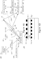
- Figure 5 is a high level flowchart illustrating a metrology measurement method 200, according to some embodiments of the invention.
- Method 200 may be at least partially implemented by at least one computer processor, e.g., in a metrology module.
- Certain embodiments comprise computer program products comprising a computer readable storage medium having computer readable program embodied therewith and configured to carry out of the relevant stages of method 200.
- Certain embodiments comprise target design files of respective targets designed by embodiments of method 200.
- Certain embodiments comprise metrology signals derived by method 200 and/or by tool 100.
- Metrology measurement method 200 comprises illuminating a stationary diffractive target by a stationary illumination source (stage 210 ), measuring a signal composed of a sum of a zeroth order diffraction signal and a first order diffraction signal (stage 220 ), repeating the measuring for a plurality of relations between the zeroth and the first order diffraction signals, while maintaining the diffractive target and the illumination source stationary (stage 230 ), and deriving the first order diffraction signal from the measured sums (stage 240 ).
- Method 200 may comprise providing coherent illuminating and measuring in the pupil plane (stage 250 ) so that illuminating 210 is carried out with coherent illumination and measuring 220, 230 are carried out in a pupil plane with respect to the target. Method 200 may further comprise selecting the illumination wavelength and the pitch of the target to yield partial overlapping of the zeroth and first diffraction orders in the pupil plane (stage 255 ).
- Method 200 may comprise providing incoherent illuminating and measuring in the field plane (stage 260 ) so that illuminating 210 is carried out with incoherent illumination and measuring 220, 230 are carried out in a field plane with respect to the target. Method 200 may further comprise masking a non-measured first order diffraction signal at the pupil plane of the target (stage 265 ) to yield the measured sum.
- Method 200 may further comprise carrying out at least two overlay measurements of an imaging target (comprising at least two periodic structures such as gratings, with same or different pitches, e.g., AIM targets), at least one of the measurements with a masked +1 diffraction order and at least another one of the measurements with a masked -1 diffraction order, and deriving an overlay by averaging the at least two overlay measurements.
- Method 200 may further comprise identifying, during a training stage, and removing inaccuracy-introducing illumination points, as explained above.
- Method 200 may comprise carrying out the repeated measuring for a plurality of phases as the relations between the zeroth and the first order diffraction signals (stage 270 ), and/or by carrying out the repeated measuring for a plurality of angles and/or phases and/or wavelengths of the illumination to modify the relations between the zeroth and the first order diffraction signals (stage 275 ).
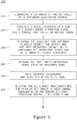
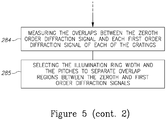
- Method 200 may comprise providing annular illumination and using targets with gratings that differ in pitch (stage 280 ), so that the illumination is annular and the diffractive target comprises at least two periodic structures having at least two corresponding different pitches.
- Method 200 may further comprise selecting the illumination width and the pitches to separate overlap regions between the zeroth and first order diffraction signals (stage 285 ), e.g., to separate overlap regions between the zeroth order diffraction signal and each of the first order diffraction signals from each of the respective periodic structures.
- Method 200 may comprise using a single cell SCOL target having gratings with different pitches (stage 282 ), measuring the single cell SCOL target with annular illumination (stage 283 ) and measuring the overlaps between the zero order diffraction signal and each first order diffraction signal of each of the gratings (stage 284 ).
- disclosed systems 100 and methods 200 provide new optical configuration which achieve a superior accuracy in scatterometry overlay measurement, improves tool performance and reduces effect of process variations. Moreover, disclosed systems 100 and methods 200 allow detecting more than a single diffraction order at the detector position in grating-over-grating target, retrieve information, by phase scan between illumination points, and organize phase scan between first diffraction orders and either zeroth diffraction order or a reference beam by either target displacement or illumination spot displacement. Scanning phase between diffraction orders may be carried out by introducing controllable aberrations in illumination, i.e. by adaptive optical elements.
- Systems 100 and methods 200 enable measurement of the modulation amplitude of the grating-over-grating target in the field plane while more than a single diffraction order is allowed at the detector.
- Systems 100 and methods 200 also enable measurement of grating-over-grating targets with different pitches and retrieval of grating positions (and overlay) by modulation of the phases of the diffraction orders and capturing respective pupil images.
- disclosed systems 100 and methods 200 improve the accuracy of overlay measurements and extend the applicability of scatterometry to previously hardly addressable layers.
- Certain embodiments of the invention may include features from different embodiments disclosed above, and certain embodiments may incorporate elements from other embodiments disclosed above.
- the disclosure of elements of the invention in the context of a specific embodiment is not to be taken as limiting their use in the specific embodiment alone.
Landscapes
- Physics & Mathematics (AREA)
- General Physics & Mathematics (AREA)
- Spectroscopy & Molecular Physics (AREA)
- Health & Medical Sciences (AREA)
- Life Sciences & Earth Sciences (AREA)
- Chemical & Material Sciences (AREA)
- Analytical Chemistry (AREA)
- Biochemistry (AREA)
- General Health & Medical Sciences (AREA)
- Immunology (AREA)
- Pathology (AREA)
- Length Measuring Devices By Optical Means (AREA)
- Exposure And Positioning Against Photoresist Photosensitive Materials (AREA)
- Investigating Or Analysing Materials By Optical Means (AREA)
Applications Claiming Priority (2)
| Application Number | Priority Date | Filing Date | Title |
|---|---|---|---|
| US201562215895P | 2015-09-09 | 2015-09-09 | |
| PCT/US2016/047619 WO2017044283A1 (en) | 2015-09-09 | 2016-08-18 | New approaches in first order scatterometry overlay based on introduction of auxiliary elecromagnetic fields |
Publications (3)
| Publication Number | Publication Date |
|---|---|
| EP3347701A1 EP3347701A1 (en) | 2018-07-18 |
| EP3347701A4 EP3347701A4 (en) | 2019-04-10 |
| EP3347701B1 true EP3347701B1 (en) | 2020-07-01 |
Family
ID=58239827
Family Applications (1)
| Application Number | Title | Priority Date | Filing Date |
|---|---|---|---|
| EP16844877.7A Active EP3347701B1 (en) | 2015-09-09 | 2016-08-18 | New approaches in first order scatterometry overlay based on introduction of auxiliary elecromagnetic fields |
Country Status (7)
| Country | Link |
|---|---|
| US (1) | US10197389B2 (ko) |
| EP (1) | EP3347701B1 (ko) |
| JP (1) | JP6827466B2 (ko) |
| KR (1) | KR102407073B1 (ko) |
| CN (1) | CN108027320B (ko) |
| TW (1) | TWI656409B (ko) |
| WO (1) | WO2017044283A1 (ko) |
Cited By (1)
| Publication number | Priority date | Publication date | Assignee | Title |
|---|---|---|---|---|
| EP3593124B1 (en) * | 2017-04-14 | 2024-01-10 | KLA - Tencor Corporation | Transmission small-angle x-ray scattering metrology system |
Families Citing this family (18)
| Publication number | Priority date | Publication date | Assignee | Title |
|---|---|---|---|---|
| US10983005B2 (en) * | 2016-12-15 | 2021-04-20 | Taiwan Semiconductor Manufacturing Co., Ltd. | Spectroscopic overlay metrology |
| US10444161B2 (en) * | 2017-04-05 | 2019-10-15 | Kla-Tencor Corporation | Systems and methods for metrology with layer-specific illumination spectra |
| US10705435B2 (en) | 2018-01-12 | 2020-07-07 | Globalfoundries Inc. | Self-referencing and self-calibrating interference pattern overlay measurement |
| CN112005169B (zh) | 2018-04-06 | 2023-03-28 | Asml荷兰有限公司 | 具有非线性光学器件的检查设备 |
| WO2019236084A1 (en) * | 2018-06-07 | 2019-12-12 | Kla-Tencor Corporation | Overlay measurement using phase and amplitude modeling |
| DE102018210315B4 (de) * | 2018-06-25 | 2021-03-18 | Carl Zeiss Smt Gmbh | Verfahren zur Erfassung einer Struktur einer Lithografiemaske sowie Vorrichtung zur Durchführung des Verfahrens |
| WO2020046408A1 (en) * | 2018-08-28 | 2020-03-05 | Kla-Tencor Corporation | Off-axis illumination overlay measurement using two-diffracted orders imaging |
| KR20210081434A (ko) | 2018-11-21 | 2021-07-01 | 케이엘에이 코포레이션 | 단일 셀 그레이 산란계측 오버레이 타겟 및 다양한 조명 파라미터를 사용한 이들의 측정 |
| JP7431824B2 (ja) * | 2018-11-21 | 2024-02-15 | ケーエルエー コーポレイション | スキャトロメトリオーバーレイ(scol)測定方法及びscol測定システム |
| US11604149B2 (en) | 2020-04-23 | 2023-03-14 | Kla Corporation | Metrology methods and optical schemes for measurement of misregistration by using hatched target designs |
| US11346657B2 (en) * | 2020-05-22 | 2022-05-31 | Kla Corporation | Measurement modes for overlay |
| US11686576B2 (en) | 2020-06-04 | 2023-06-27 | Kla Corporation | Metrology target for one-dimensional measurement of periodic misregistration |
| US11164307B1 (en) | 2020-07-21 | 2021-11-02 | Kla Corporation | Misregistration metrology by using fringe Moiré and optical Moiré effects |
| US11300405B2 (en) * | 2020-08-03 | 2022-04-12 | Kla Corporation | Grey-mode scanning scatterometry overlay metrology |
| US11841621B2 (en) * | 2021-10-29 | 2023-12-12 | KLA Corporation CA | Moiré scatterometry overlay |
| US11796925B2 (en) | 2022-01-03 | 2023-10-24 | Kla Corporation | Scanning overlay metrology using overlay targets having multiple spatial frequencies |
| US11861824B1 (en) * | 2022-02-03 | 2024-01-02 | Kla Corporation | Reference image grouping in overlay metrology |
| US12032300B2 (en) | 2022-02-14 | 2024-07-09 | Kla Corporation | Imaging overlay with mutually coherent oblique illumination |
Family Cites Families (16)
| Publication number | Priority date | Publication date | Assignee | Title |
|---|---|---|---|---|
| JPH0536586A (ja) * | 1991-08-02 | 1993-02-12 | Canon Inc | 像投影方法及び該方法を用いた半導体デバイスの製造方法 |
| US6710876B1 (en) | 2000-08-14 | 2004-03-23 | Kla-Tencor Technologies Corporation | Metrology system using optical phase |
| JP2002116314A (ja) | 2000-10-06 | 2002-04-19 | Sankyo Seiki Mfg Co Ltd | 回折素子および光ピックアップ装置 |
| US7791727B2 (en) * | 2004-08-16 | 2010-09-07 | Asml Netherlands B.V. | Method and apparatus for angular-resolved spectroscopic lithography characterization |
| US20070002336A1 (en) | 2005-06-30 | 2007-01-04 | Asml Netherlands B.V. | Metrology apparatus, lithographic apparatus, process apparatus, metrology method and device manufacturing method |
| US7467064B2 (en) * | 2006-02-07 | 2008-12-16 | Timbre Technologies, Inc. | Transforming metrology data from a semiconductor treatment system using multivariate analysis |
| NL1036123A1 (nl) * | 2007-11-13 | 2009-05-14 | Asml Netherlands Bv | Inspection method and apparatus, lithographic apparatus, lithographic processing cell and device manufacturing method. |
| US9188875B2 (en) * | 2008-12-16 | 2015-11-17 | Asml Netherlands B.V. | Calibration method, inspection method and apparatus, lithographic apparatus, and lithographic processing cell |
| NL2004094A (en) * | 2009-02-11 | 2010-08-12 | Asml Netherlands Bv | Inspection apparatus, lithographic apparatus, lithographic processing cell and inspection method. |
| NL2007127A (en) * | 2010-08-06 | 2012-02-07 | Asml Netherlands Bv | Inspection apparatus and method, lithographic apparatus and lithographic processing cell. |
| JP6312664B2 (ja) * | 2012-06-26 | 2018-04-18 | ケーエルエー−テンカー コーポレイション | 近接場計測 |
| US8913237B2 (en) * | 2012-06-26 | 2014-12-16 | Kla-Tencor Corporation | Device-like scatterometry overlay targets |
| WO2014062972A1 (en) * | 2012-10-18 | 2014-04-24 | Kla-Tencor Corporation | Symmetric target design in scatterometry overlay metrology |
| NL2013210A (en) * | 2013-08-07 | 2015-02-10 | Asml Netherlands Bv | Metrology method and apparatus, lithographic system and device manufacturing method. |
| US9490182B2 (en) * | 2013-12-23 | 2016-11-08 | Kla-Tencor Corporation | Measurement of multiple patterning parameters |
| CN106662824B (zh) * | 2014-07-09 | 2018-07-24 | Asml荷兰有限公司 | 检查装置、检查方法和设备制造方法 |
-
2015
- 2015-12-28 TW TW104144070A patent/TWI656409B/zh active
-
2016
- 2016-08-18 EP EP16844877.7A patent/EP3347701B1/en active Active
- 2016-08-18 WO PCT/US2016/047619 patent/WO2017044283A1/en active Application Filing
- 2016-08-18 KR KR1020187009582A patent/KR102407073B1/ko active IP Right Grant
- 2016-08-18 JP JP2018512605A patent/JP6827466B2/ja active Active
- 2016-08-18 US US15/305,166 patent/US10197389B2/en active Active
- 2016-08-18 CN CN201680051708.7A patent/CN108027320B/zh active Active
Non-Patent Citations (1)
| Title |
|---|
| None * |
Cited By (1)
| Publication number | Priority date | Publication date | Assignee | Title |
|---|---|---|---|---|
| EP3593124B1 (en) * | 2017-04-14 | 2024-01-10 | KLA - Tencor Corporation | Transmission small-angle x-ray scattering metrology system |
Also Published As
| Publication number | Publication date |
|---|---|
| JP2018529952A (ja) | 2018-10-11 |
| US20170268869A1 (en) | 2017-09-21 |
| KR20180039743A (ko) | 2018-04-18 |
| CN108027320A (zh) | 2018-05-11 |
| CN108027320B (zh) | 2022-10-04 |
| US10197389B2 (en) | 2019-02-05 |
| TWI656409B (zh) | 2019-04-11 |
| WO2017044283A1 (en) | 2017-03-16 |
| JP6827466B2 (ja) | 2021-02-10 |
| KR102407073B1 (ko) | 2022-06-08 |
| EP3347701A4 (en) | 2019-04-10 |
| TW201710799A (zh) | 2017-03-16 |
| EP3347701A1 (en) | 2018-07-18 |
Similar Documents
| Publication | Publication Date | Title |
|---|---|---|
| EP3347701B1 (en) | New approaches in first order scatterometry overlay based on introduction of auxiliary elecromagnetic fields | |
| US7528953B2 (en) | Target acquisition and overlay metrology based on two diffracted orders imaging | |
| JP6879939B2 (ja) | オーバレイ計測用トポグラフィック位相制御 | |
| US10107765B2 (en) | Apparatus, techniques, and target designs for measuring semiconductor parameters | |
| US20240210841A9 (en) | Imaging overlay targets using moiré elements and rotational symmetry arrangements | |
| US6775015B2 (en) | Optical metrology of single features | |
| US5493403A (en) | Method and apparatus for the alignment of a substrate | |
| US9222897B2 (en) | Method for characterizing a feature on a mask and device for carrying out the method | |
| JP2020510195A (ja) | 光学散乱計測に基づくプロセスに対してロバストなオーバーレイ計測 | |
| US11164307B1 (en) | Misregistration metrology by using fringe Moiré and optical Moiré effects | |
| JP2018517920A (ja) | メトロロジ方法及び装置、コンピュータプログラム、並びにリソグラフィシステム | |
| WO2004023214A1 (en) | Interferometry-based method and apparatus for overlay metrology | |
| TWI791866B (zh) | 量測一度量目標之方法,電腦程式產品,度量模組,以及度量工具 | |
| WO2005116577A1 (ja) | 結像光学系の調整方法、結像装置、位置ずれ検出装置、マ-ク識別装置及びエッジ位置検出装置 | |
| CN111566564A (zh) | 基于衍射的叠加散射测量 | |
| WO2019118039A1 (en) | Enhancing metrology target information content | |
| US10622238B2 (en) | Overlay measurement using phase and amplitude modeling | |
| TW201839874A (zh) | 基於繞射之重疊散射術 | |
| US20230236113A1 (en) | Annular apodizer for small target overlay measurement |
Legal Events
| Date | Code | Title | Description |
|---|---|---|---|
| STAA | Information on the status of an ep patent application or granted ep patent |
Free format text: STATUS: THE INTERNATIONAL PUBLICATION HAS BEEN MADE |
|
| PUAI | Public reference made under article 153(3) epc to a published international application that has entered the european phase |
Free format text: ORIGINAL CODE: 0009012 |
|
| STAA | Information on the status of an ep patent application or granted ep patent |
Free format text: STATUS: REQUEST FOR EXAMINATION WAS MADE |
|
| 17P | Request for examination filed |
Effective date: 20180326 |
|
| AK | Designated contracting states |
Kind code of ref document: A1 Designated state(s): AL AT BE BG CH CY CZ DE DK EE ES FI FR GB GR HR HU IE IS IT LI LT LU LV MC MK MT NL NO PL PT RO RS SE SI SK SM TR |
|
| AX | Request for extension of the european patent |
Extension state: BA ME |
|
| DAV | Request for validation of the european patent (deleted) | ||
| DAX | Request for extension of the european patent (deleted) | ||
| A4 | Supplementary search report drawn up and despatched |
Effective date: 20190311 |
|
| RIC1 | Information provided on ipc code assigned before grant |
Ipc: G01B 9/02 20060101ALI20190305BHEP Ipc: G01J 3/44 20060101ALI20190305BHEP Ipc: G01N 21/47 20060101AFI20190305BHEP Ipc: G01B 11/27 20060101ALI20190305BHEP Ipc: G03F 7/20 20060101ALI20190305BHEP |
|
| GRAP | Despatch of communication of intention to grant a patent |
Free format text: ORIGINAL CODE: EPIDOSNIGR1 |
|
| STAA | Information on the status of an ep patent application or granted ep patent |
Free format text: STATUS: GRANT OF PATENT IS INTENDED |
|
| INTG | Intention to grant announced |
Effective date: 20200320 |
|
| GRAS | Grant fee paid |
Free format text: ORIGINAL CODE: EPIDOSNIGR3 |
|
| GRAA | (expected) grant |
Free format text: ORIGINAL CODE: 0009210 |
|
| STAA | Information on the status of an ep patent application or granted ep patent |
Free format text: STATUS: THE PATENT HAS BEEN GRANTED |
|
| AK | Designated contracting states |
Kind code of ref document: B1 Designated state(s): AL AT BE BG CH CY CZ DE DK EE ES FI FR GB GR HR HU IE IS IT LI LT LU LV MC MK MT NL NO PL PT RO RS SE SI SK SM TR |
|
| REG | Reference to a national code |
Ref country code: AT Ref legal event code: REF Ref document number: 1286623 Country of ref document: AT Kind code of ref document: T Effective date: 20200715 Ref country code: CH Ref legal event code: EP |
|
| REG | Reference to a national code |
Ref country code: IE Ref legal event code: FG4D |
|
| REG | Reference to a national code |
Ref country code: DE Ref legal event code: R096 Ref document number: 602016039288 Country of ref document: DE |
|
| REG | Reference to a national code |
Ref country code: NL Ref legal event code: FP |
|
| REG | Reference to a national code |
Ref country code: LT Ref legal event code: MG4D |
|
| PG25 | Lapsed in a contracting state [announced via postgrant information from national office to epo] |
Ref country code: BG Free format text: LAPSE BECAUSE OF FAILURE TO SUBMIT A TRANSLATION OF THE DESCRIPTION OR TO PAY THE FEE WITHIN THE PRESCRIBED TIME-LIMIT Effective date: 20201001 |
|
| REG | Reference to a national code |
Ref country code: AT Ref legal event code: MK05 Ref document number: 1286623 Country of ref document: AT Kind code of ref document: T Effective date: 20200701 |
|
| PG25 | Lapsed in a contracting state [announced via postgrant information from national office to epo] |
Ref country code: SE Free format text: LAPSE BECAUSE OF FAILURE TO SUBMIT A TRANSLATION OF THE DESCRIPTION OR TO PAY THE FEE WITHIN THE PRESCRIBED TIME-LIMIT Effective date: 20200701 Ref country code: FI Free format text: LAPSE BECAUSE OF FAILURE TO SUBMIT A TRANSLATION OF THE DESCRIPTION OR TO PAY THE FEE WITHIN THE PRESCRIBED TIME-LIMIT Effective date: 20200701 Ref country code: GR Free format text: LAPSE BECAUSE OF FAILURE TO SUBMIT A TRANSLATION OF THE DESCRIPTION OR TO PAY THE FEE WITHIN THE PRESCRIBED TIME-LIMIT Effective date: 20201002 Ref country code: CZ Free format text: LAPSE BECAUSE OF FAILURE TO SUBMIT A TRANSLATION OF THE DESCRIPTION OR TO PAY THE FEE WITHIN THE PRESCRIBED TIME-LIMIT Effective date: 20200701 Ref country code: AT Free format text: LAPSE BECAUSE OF FAILURE TO SUBMIT A TRANSLATION OF THE DESCRIPTION OR TO PAY THE FEE WITHIN THE PRESCRIBED TIME-LIMIT Effective date: 20200701 Ref country code: ES Free format text: LAPSE BECAUSE OF FAILURE TO SUBMIT A TRANSLATION OF THE DESCRIPTION OR TO PAY THE FEE WITHIN THE PRESCRIBED TIME-LIMIT Effective date: 20200701 Ref country code: NO Free format text: LAPSE BECAUSE OF FAILURE TO SUBMIT A TRANSLATION OF THE DESCRIPTION OR TO PAY THE FEE WITHIN THE PRESCRIBED TIME-LIMIT Effective date: 20201001 Ref country code: HR Free format text: LAPSE BECAUSE OF FAILURE TO SUBMIT A TRANSLATION OF THE DESCRIPTION OR TO PAY THE FEE WITHIN THE PRESCRIBED TIME-LIMIT Effective date: 20200701 Ref country code: PT Free format text: LAPSE BECAUSE OF FAILURE TO SUBMIT A TRANSLATION OF THE DESCRIPTION OR TO PAY THE FEE WITHIN THE PRESCRIBED TIME-LIMIT Effective date: 20201102 Ref country code: LT Free format text: LAPSE BECAUSE OF FAILURE TO SUBMIT A TRANSLATION OF THE DESCRIPTION OR TO PAY THE FEE WITHIN THE PRESCRIBED TIME-LIMIT Effective date: 20200701 |
|
| PG25 | Lapsed in a contracting state [announced via postgrant information from national office to epo] |
Ref country code: IS Free format text: LAPSE BECAUSE OF FAILURE TO SUBMIT A TRANSLATION OF THE DESCRIPTION OR TO PAY THE FEE WITHIN THE PRESCRIBED TIME-LIMIT Effective date: 20201101 Ref country code: PL Free format text: LAPSE BECAUSE OF FAILURE TO SUBMIT A TRANSLATION OF THE DESCRIPTION OR TO PAY THE FEE WITHIN THE PRESCRIBED TIME-LIMIT Effective date: 20200701 Ref country code: LV Free format text: LAPSE BECAUSE OF FAILURE TO SUBMIT A TRANSLATION OF THE DESCRIPTION OR TO PAY THE FEE WITHIN THE PRESCRIBED TIME-LIMIT Effective date: 20200701 Ref country code: RS Free format text: LAPSE BECAUSE OF FAILURE TO SUBMIT A TRANSLATION OF THE DESCRIPTION OR TO PAY THE FEE WITHIN THE PRESCRIBED TIME-LIMIT Effective date: 20200701 |
|
| PG25 | Lapsed in a contracting state [announced via postgrant information from national office to epo] |
Ref country code: MC Free format text: LAPSE BECAUSE OF FAILURE TO SUBMIT A TRANSLATION OF THE DESCRIPTION OR TO PAY THE FEE WITHIN THE PRESCRIBED TIME-LIMIT Effective date: 20200701 |
|
| REG | Reference to a national code |
Ref country code: CH Ref legal event code: PL |
|
| REG | Reference to a national code |
Ref country code: DE Ref legal event code: R097 Ref document number: 602016039288 Country of ref document: DE |
|
| PG25 | Lapsed in a contracting state [announced via postgrant information from national office to epo] |
Ref country code: DK Free format text: LAPSE BECAUSE OF FAILURE TO SUBMIT A TRANSLATION OF THE DESCRIPTION OR TO PAY THE FEE WITHIN THE PRESCRIBED TIME-LIMIT Effective date: 20200701 Ref country code: CH Free format text: LAPSE BECAUSE OF NON-PAYMENT OF DUE FEES Effective date: 20200831 Ref country code: RO Free format text: LAPSE BECAUSE OF FAILURE TO SUBMIT A TRANSLATION OF THE DESCRIPTION OR TO PAY THE FEE WITHIN THE PRESCRIBED TIME-LIMIT Effective date: 20200701 Ref country code: LI Free format text: LAPSE BECAUSE OF NON-PAYMENT OF DUE FEES Effective date: 20200831 Ref country code: LU Free format text: LAPSE BECAUSE OF NON-PAYMENT OF DUE FEES Effective date: 20200818 Ref country code: EE Free format text: LAPSE BECAUSE OF FAILURE TO SUBMIT A TRANSLATION OF THE DESCRIPTION OR TO PAY THE FEE WITHIN THE PRESCRIBED TIME-LIMIT Effective date: 20200701 Ref country code: IT Free format text: LAPSE BECAUSE OF FAILURE TO SUBMIT A TRANSLATION OF THE DESCRIPTION OR TO PAY THE FEE WITHIN THE PRESCRIBED TIME-LIMIT Effective date: 20200701 Ref country code: SM Free format text: LAPSE BECAUSE OF FAILURE TO SUBMIT A TRANSLATION OF THE DESCRIPTION OR TO PAY THE FEE WITHIN THE PRESCRIBED TIME-LIMIT Effective date: 20200701 |
|
| PLBE | No opposition filed within time limit |
Free format text: ORIGINAL CODE: 0009261 |
|
| STAA | Information on the status of an ep patent application or granted ep patent |
Free format text: STATUS: NO OPPOSITION FILED WITHIN TIME LIMIT |
|
| REG | Reference to a national code |
Ref country code: BE Ref legal event code: MM Effective date: 20200831 |
|
| PG25 | Lapsed in a contracting state [announced via postgrant information from national office to epo] |
Ref country code: AL Free format text: LAPSE BECAUSE OF FAILURE TO SUBMIT A TRANSLATION OF THE DESCRIPTION OR TO PAY THE FEE WITHIN THE PRESCRIBED TIME-LIMIT Effective date: 20200701 |
|
| 26N | No opposition filed |
Effective date: 20210406 |
|
| GBPC | Gb: european patent ceased through non-payment of renewal fee |
Effective date: 20201001 |
|
| PG25 | Lapsed in a contracting state [announced via postgrant information from national office to epo] |
Ref country code: SK Free format text: LAPSE BECAUSE OF FAILURE TO SUBMIT A TRANSLATION OF THE DESCRIPTION OR TO PAY THE FEE WITHIN THE PRESCRIBED TIME-LIMIT Effective date: 20200701 |
|
| PG25 | Lapsed in a contracting state [announced via postgrant information from national office to epo] |
Ref country code: IE Free format text: LAPSE BECAUSE OF NON-PAYMENT OF DUE FEES Effective date: 20200818 Ref country code: GB Free format text: LAPSE BECAUSE OF NON-PAYMENT OF DUE FEES Effective date: 20201001 Ref country code: SI Free format text: LAPSE BECAUSE OF FAILURE TO SUBMIT A TRANSLATION OF THE DESCRIPTION OR TO PAY THE FEE WITHIN THE PRESCRIBED TIME-LIMIT Effective date: 20200701 Ref country code: BE Free format text: LAPSE BECAUSE OF NON-PAYMENT OF DUE FEES Effective date: 20200831 |
|
| PG25 | Lapsed in a contracting state [announced via postgrant information from national office to epo] |
Ref country code: TR Free format text: LAPSE BECAUSE OF FAILURE TO SUBMIT A TRANSLATION OF THE DESCRIPTION OR TO PAY THE FEE WITHIN THE PRESCRIBED TIME-LIMIT Effective date: 20200701 Ref country code: MT Free format text: LAPSE BECAUSE OF FAILURE TO SUBMIT A TRANSLATION OF THE DESCRIPTION OR TO PAY THE FEE WITHIN THE PRESCRIBED TIME-LIMIT Effective date: 20200701 Ref country code: CY Free format text: LAPSE BECAUSE OF FAILURE TO SUBMIT A TRANSLATION OF THE DESCRIPTION OR TO PAY THE FEE WITHIN THE PRESCRIBED TIME-LIMIT Effective date: 20200701 |
|
| PG25 | Lapsed in a contracting state [announced via postgrant information from national office to epo] |
Ref country code: MK Free format text: LAPSE BECAUSE OF FAILURE TO SUBMIT A TRANSLATION OF THE DESCRIPTION OR TO PAY THE FEE WITHIN THE PRESCRIBED TIME-LIMIT Effective date: 20200701 |
|
| P01 | Opt-out of the competence of the unified patent court (upc) registered |
Effective date: 20230525 |
|
| PGFP | Annual fee paid to national office [announced via postgrant information from national office to epo] |
Ref country code: NL Payment date: 20230826 Year of fee payment: 8 |
|
| PGFP | Annual fee paid to national office [announced via postgrant information from national office to epo] |
Ref country code: FR Payment date: 20230825 Year of fee payment: 8 Ref country code: DE Payment date: 20230829 Year of fee payment: 8 |