EP3347127B2 - Übertragungsvorrichtung - Google Patents
Übertragungsvorrichtung Download PDFInfo
- Publication number
- EP3347127B2 EP3347127B2 EP16770540.9A EP16770540A EP3347127B2 EP 3347127 B2 EP3347127 B2 EP 3347127B2 EP 16770540 A EP16770540 A EP 16770540A EP 3347127 B2 EP3347127 B2 EP 3347127B2
- Authority
- EP
- European Patent Office
- Prior art keywords
- port
- door
- alpha
- beta
- flange
- Prior art date
- Legal status (The legal status is an assumption and is not a legal conclusion. Google has not performed a legal analysis and makes no representation as to the accuracy of the status listed.)
- Active
Links
Images


Classifications
-
- B—PERFORMING OPERATIONS; TRANSPORTING
- B01—PHYSICAL OR CHEMICAL PROCESSES OR APPARATUS IN GENERAL
- B01L—CHEMICAL OR PHYSICAL LABORATORY APPARATUS FOR GENERAL USE
- B01L3/00—Containers or dishes for laboratory use, e.g. laboratory glassware; Droppers
- B01L3/56—Labware specially adapted for transferring fluids
- B01L3/563—Joints or fittings ; Separable fluid transfer means to transfer fluids between at least two containers, e.g. connectors
-
- B—PERFORMING OPERATIONS; TRANSPORTING
- B65—CONVEYING; PACKING; STORING; HANDLING THIN OR FILAMENTARY MATERIAL
- B65G—TRANSPORT OR STORAGE DEVICES, e.g. CONVEYORS FOR LOADING OR TIPPING, SHOP CONVEYOR SYSTEMS OR PNEUMATIC TUBE CONVEYORS
- B65G53/00—Conveying materials in bulk through troughs, pipes or tubes by floating the materials or by flow of gas, liquid or foam
- B65G53/34—Details
- B65G53/40—Feeding or discharging devices
- B65G53/46—Gates or sluices, e.g. rotary wheels
- B65G53/4691—Gates or sluices, e.g. rotary wheels of air-lock type, i.e. at least two valves opening asynchronously
-
- B—PERFORMING OPERATIONS; TRANSPORTING
- B01—PHYSICAL OR CHEMICAL PROCESSES OR APPARATUS IN GENERAL
- B01L—CHEMICAL OR PHYSICAL LABORATORY APPARATUS FOR GENERAL USE
- B01L1/00—Enclosures; Chambers
- B01L1/02—Air-pressure chambers; Air-locks therefor
-
- B—PERFORMING OPERATIONS; TRANSPORTING
- B01—PHYSICAL OR CHEMICAL PROCESSES OR APPARATUS IN GENERAL
- B01L—CHEMICAL OR PHYSICAL LABORATORY APPARATUS FOR GENERAL USE
- B01L1/00—Enclosures; Chambers
- B01L1/02—Air-pressure chambers; Air-locks therefor
- B01L1/025—Environmental chambers
-
- B—PERFORMING OPERATIONS; TRANSPORTING
- B01—PHYSICAL OR CHEMICAL PROCESSES OR APPARATUS IN GENERAL
- B01L—CHEMICAL OR PHYSICAL LABORATORY APPARATUS FOR GENERAL USE
- B01L1/00—Enclosures; Chambers
- B01L1/04—Dust-free rooms or enclosures
-
- B—PERFORMING OPERATIONS; TRANSPORTING
- B01—PHYSICAL OR CHEMICAL PROCESSES OR APPARATUS IN GENERAL
- B01L—CHEMICAL OR PHYSICAL LABORATORY APPARATUS FOR GENERAL USE
- B01L3/00—Containers or dishes for laboratory use, e.g. laboratory glassware; Droppers
-
- B—PERFORMING OPERATIONS; TRANSPORTING
- B01—PHYSICAL OR CHEMICAL PROCESSES OR APPARATUS IN GENERAL
- B01L—CHEMICAL OR PHYSICAL LABORATORY APPARATUS FOR GENERAL USE
- B01L3/00—Containers or dishes for laboratory use, e.g. laboratory glassware; Droppers
- B01L3/56—Labware specially adapted for transferring fluids
- B01L3/565—Seals
-
- B—PERFORMING OPERATIONS; TRANSPORTING
- B65—CONVEYING; PACKING; STORING; HANDLING THIN OR FILAMENTARY MATERIAL
- B65B—MACHINES, APPARATUS OR DEVICES FOR, OR METHODS OF, PACKAGING ARTICLES OR MATERIALS; UNPACKING
- B65B17/00—Other machines, apparatus, or methods for packaging articles or materials
- B65B17/02—Joining articles, e.g. cans, directly to each other for convenience of storage, transport, or handling
-
- B—PERFORMING OPERATIONS; TRANSPORTING
- B65—CONVEYING; PACKING; STORING; HANDLING THIN OR FILAMENTARY MATERIAL
- B65G—TRANSPORT OR STORAGE DEVICES, e.g. CONVEYORS FOR LOADING OR TIPPING, SHOP CONVEYOR SYSTEMS OR PNEUMATIC TUBE CONVEYORS
- B65G53/00—Conveying materials in bulk through troughs, pipes or tubes by floating the materials or by flow of gas, liquid or foam
- B65G53/34—Details
- B65G53/40—Feeding or discharging devices
- B65G53/46—Gates or sluices, e.g. rotary wheels
-
- B—PERFORMING OPERATIONS; TRANSPORTING
- B65—CONVEYING; PACKING; STORING; HANDLING THIN OR FILAMENTARY MATERIAL
- B65G—TRANSPORT OR STORAGE DEVICES, e.g. CONVEYORS FOR LOADING OR TIPPING, SHOP CONVEYOR SYSTEMS OR PNEUMATIC TUBE CONVEYORS
- B65G69/00—Auxiliary measures taken, or devices used, in connection with loading or unloading
- B65G69/18—Preventing escape of dust
- B65G69/181—Preventing escape of dust by means of sealed systems
- B65G69/183—Preventing escape of dust by means of sealed systems with co-operating closure members on each of the parts of a separable transfer channel
-
- B—PERFORMING OPERATIONS; TRANSPORTING
- B01—PHYSICAL OR CHEMICAL PROCESSES OR APPARATUS IN GENERAL
- B01L—CHEMICAL OR PHYSICAL LABORATORY APPARATUS FOR GENERAL USE
- B01L2200/00—Solutions for specific problems relating to chemical or physical laboratory apparatus
- B01L2200/02—Adapting objects or devices to another
- B01L2200/026—Fluid interfacing between devices or objects, e.g. connectors, inlet details
-
- B—PERFORMING OPERATIONS; TRANSPORTING
- B01—PHYSICAL OR CHEMICAL PROCESSES OR APPARATUS IN GENERAL
- B01L—CHEMICAL OR PHYSICAL LABORATORY APPARATUS FOR GENERAL USE
- B01L2200/00—Solutions for specific problems relating to chemical or physical laboratory apparatus
- B01L2200/14—Process control and prevention of errors
- B01L2200/141—Preventing contamination, tampering
-
- B—PERFORMING OPERATIONS; TRANSPORTING
- B01—PHYSICAL OR CHEMICAL PROCESSES OR APPARATUS IN GENERAL
- B01L—CHEMICAL OR PHYSICAL LABORATORY APPARATUS FOR GENERAL USE
- B01L2300/00—Additional constructional details
- B01L2300/04—Closures and closing means
-
- B—PERFORMING OPERATIONS; TRANSPORTING
- B01—PHYSICAL OR CHEMICAL PROCESSES OR APPARATUS IN GENERAL
- B01L—CHEMICAL OR PHYSICAL LABORATORY APPARATUS FOR GENERAL USE
- B01L2300/00—Additional constructional details
- B01L2300/04—Closures and closing means
- B01L2300/046—Function or devices integrated in the closure
Definitions
- the present invention relates to a transfer device and method for transferring material.
- the invention relates to apparatus and method for assisting in material transfer during manufacturing processes which may be undertaken in a traditional clean room or in an isolation and/or containment system employed for operator and/or process protection.
- sterility is of fundamental concern in many manufacturing processes, to safeguard against contamination of products being manufactured in the process.
- Exemplary industries using aseptic production in a traditional manner or in isolation and/or containment facilities include pharmaceutical, medical device, biotechnological and food industries.
- RTP rapid transfer
- the alpha and beta port are preferably engageable with one another and secured thereby via mating means.
- the mating means may comprise a male member disposed on one of the alpha or beta port and a female member disposed on the other.
- the male member comprises a bayonet fixing and the female a complementarily shaped recess.
- the male member is disposed on the beta port and the female member on the alpha port.
- each port comprises a plurality of mating members.
- the mating members may be disposed on the doors to the alpha and beta.
- the mating means may comprise a bayonet fitting, a push-fit connection or other suitable means.
- the beta port may comprise a protective member.
- the protective member may comprise a funnel shaped to overlie the junction between the alpha and beta and permit the passage of material therethrough.
- the protective member further comprises a gaiter.
- the gaiter is suitably made from a flexible material to enable the gaiter to permit movement of the protective member from a first stowed configuration whereby the protective member does not overlie the junction between alpha and beta ports and can be retained behind the door of the beta when the door is engaged in its closed configuration and movement to a deployed, extended configuration whereby the protective member is capable of overlying the junction between the alpha and beta port.
- the flexible wall has means to determine the degree of deformation of the wall when moved from the stowed to the deployed configuration. Most suitably, this consists of two convolutes or segments giving a defined position when stowed and a defined position when deployed. More suitably still, there is an absence of a stable intermediate position.
- the means comprises annular wall thickenings at predetermined positions.
- the gaiter may comprise a flexible wall sufficiently rigid to hold the protective member in position in either configuration but flexible enough to permit movement.
- the protective member and gaiter may be integrally formed.
- the flexible wall of the gaiter may be integrally formed with a transfer bag.
- the protective member may be moved between its configurations by externally applied force.
- the protective member may be operatively connected to actuating means disposed on a transfer bag which enable an operator to move the protective member between its configurations.
- the actuating means may comprise a handle which an operator may use to apply force to move the protective member between its configurations.
- the alpha port may be associated with actuating means for controlling the opening and closing of the ports.
- the actuator may be operatively connected to the door of the alpha port.
- the actuator may be capable of translational movement of the door and rotational movement of the door.
- the actuator may be operatively connected to a curved arm to which the door is mounted at one end and to which the other end is mounted on a shoulder, wherein the shoulder is capable of translational movement to move the door rearwardly from the alpha port and capable of rotational movement to pivot the door away from the alpha port such the door does not obstruct the port.
- Pivoting the door away from the alpha port as described above reduces the impact of such a mechanism on the air flow with an enclosure.
- an enclosure will have means for generating airflow in the ceiling which will displace air downwardly away from the ceiling.
- the door being moved out of the way of the port as described above ensures that the door has a relatively low profile and is disposed close to the enclosure wall when opened and moved out of the way of the port. Thus there is minimal profile of the door and its arm to present to the airflow thus reducing the impact of the door being open on the functioning of the enclosure.
- the alpha port may further be associated with a chute for directing material way from the alpha port when transferred into the chamber.
- the beta port may also comprise means to permanently engage the door once the door has been opened and then reengaged with and the port and in its closed configuration.
- the protective member is suitably externally operated to move between its configurations.
- the protective member is suitably externally operated of the enclosed volume of the isolator barrier chamber and/or where the beta port or second port is connected to a transfer container, for example, the enclosed volume of the transfer container.
- the opening and closing of the doors may be automated.
- the system may be used for a rapid transfer port (RTP) system.
- RTP rapid transfer port
- the enclosure may comprise any one or more of the following: chamber, isolator chamber, restrictive access barrier (RAB), screen or the like.
- RAB restrictive access barrier
- the system or device may be an aseptic transfer system or device.
- the system may further comprise a module comprising a housing defining an enclosed chamber with an inlet and an outlet.
- the inlet is connectable to the beta port and the outlet is connectable to an enclosure.
- the inlet comprises the alpha port.
- the module permits the system to be used on enclosures not having an alpha port as described hereinabove but having a closable inlet to which the outlet of the module may connect.
- the figures show an assembly 10 ( Fig. 1 ) having a passive beta port 12 and an active alpha port 14, the passive and the active are complementarily shaped such that they can engage with one another.
- the passive beta port 12 has an annular flange 16 defining an annular opening to which is releasably securable a passive port door 18. Disposed at the distal end of the passive 12, at the opposite end to the annular flange 16 is an annular clamp 22 having two handles 24.
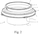
- the protective member 28 Disposed between the annular ring 16 and the annular clamp 22 is the gaiter 26 of the protective member 28 ( Fig. 2 ).
- the protective member has a cylindrical body 30 forming a funnel through which material may pass.
- the free end 32 is sized so as to be capable of passing through the port formed between the alpha and beta ports 12, 14.
- the other end 34 of the protective member 28 comprises a circular clamp flange 36 for co-operating with annular clamp 22 to secure a flexible walled container therebetween (not shown).
- a circular clamp flange 36 Extending between clamp flange 36 and port flange 16 flexible gaiter 26 which enables the protective member 28 to move from a stowed configuration in which the cylindrical body 30 extends near to, or preferably slightly beyond the flange 16 ( Fig. 3 ) and the extended configuration in which the cylindrical body 30 extends significantly beyond the flange 16 ( Fig. 2 ).
- the gaiter 26 has a flexible wall 38 which when lengthened, in the stowed configuration of the protective member, has a narrow section 40 proximal to the flange 36 and a wider section 42 proximal to the flange 16.
- the flexible wall has a waist 44 at which the gaiter 26 widens from the flange 36 towards the flange 16.
- the gaiter 26 is formed in such a manner so as to have a number of discrete configurations.
- the flexible wall 38 of the gaiter 26 has annular thickenings to provide the means for determining the discrete configurations such that the movement of the protective member 28 from its stowed configuration to its extended configuration, and vice versa, is pre-determined so that the cylindrical body will extend a predetermined distance beyond the flange 36 and provides positive feedback to a user so that they can be certain that the protective member has been successfully deployed in the correct position.
- This consists of two convolutes or segments giving a defined position when stowed and a defined position when deployed.
- Fig. 4 shows the beta port 12 with passive door 18 detached.
- the passive door 18 has a hollow generally frustoconical body having circular planar end wall 45 and an open end 46 having four slots 47 disposed equidistantly circumferentially and complementarily shaped to the locating tabs 58 on annular flange 16, so as to receive the tabs 58 to selective retain the door 18 in place.
- Circumferentially and equidistantly disposed around the end wall 45 are locating tabs 48 complementarily shaped to retaining groves 49 disposed on the door 50 of the active port.
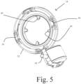
- Fig. 5 shows the alpha port 14 closed with alpha port door 50 in its closed configuration, engaged with annular flange 52.
- an actuator 54 for actuating opening and closing of the alpha/beta ports when engaged.
- the annular flange 52 has four recessed slots 56 disposed equidistantly around its circumference.
- the slots are complementarily shaped to that of the bayonet locating tabs 58 disposed equidistantly about the circumference of annular ring 16 of the beta port.
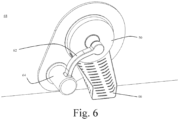
- Fig. 6 shows the alpha port door 50 in its closed configuration from inside the isolator barrier chamber.
- actuating arm 62 which has a curved profile which is fixed at one end to an extendable shoulder 64 which also is capable of pivoting the arm away from the alpha port when in an open configuration.
- Extending from the lower circumference of the inner face of flange 52 is a chute 66 for receiving material and directing it away from the inner wall 68 of the chamber.
- the actuating arm 62 has a curved profile to provide a clearance with the chute when the alpha port door is closed.
- the pivot is located below and to one side of the chute to provide ergonomic opening of the door, meaning that (1) the angle of rotation required to open the door is preferably not more than 90 degrees, (2) the torque required to open or close the door is within ergonomic ranges, and (3) the arc of movement is such that the weight of the door provides a stable position when the door is open and a stable position when closed.
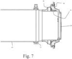
- Fig. 7 shows the beta port attached to a container 69.
- the alpha and beta ports are connected; flanges 16 and 52 are engaged.
- the doors 18 and 50 are still in their closed configuration.
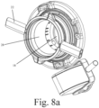
- Figs. 8a and b show the doors 18 and 50 disengaged with their respective flanges 16, 52 and they have been translationally displaced toward the interior of the chamber.
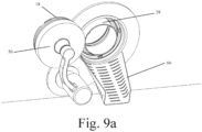
- Figs. 9 a to c show the alpha and beta ports in a third configuration: the doors 18, 50 are engaged with one another; the door of the alpha port 50 disengaged from its respective flange 16 52; the Beta port door 18, disengaged from lugs 58 that lie on the internal surface of the proximal flange 16; and the actuating arm has pivoted about shoulder 64, rotating the doors 18, 50 out of the path of the alpha and beta ports such that there is a through hole therebetween connecting the chamber with the interior of the container to which the beta port can be secured.
- the cylindrical body 30 of the protective member 28 can be seen in its stowed configuration.
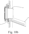
- Figs. 10a and b show the third configuration of the alpha and beta ports ( Figs. 9a to c ) but with the protective member 28 deployed in its extended configuration.
- the flexible wall of the gaiter has deformed to permit the protective member to move to its extended configuration and the predetermined positions provided by the annular thickenings are clearly seen.
- the cylindrical body 30 now extends over the junction between the alpha and beta ports and into the chamber, above the chute 66. Material can now be safely transferred through the ports without fear of contamination from any contaminants which may be present at the junction between the ports.
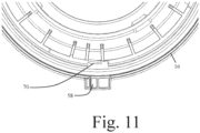
- Fig. 11 shows a lock out function on the beta port which prevents the beta from being reused which will help maintain aseptic conditions.
- the lock out function ensures that when the door 18 is re-engaged with the flange 16 of the beta, the door is permanently fixed to the flange preventing reopening and reuse of the container and its port.
- the lock out feature comprises a non-return clip 70 on the internal surface of the proximal Passive flange, which prevents the lugs and slots of Passive door 20 and Passive flange 16 being rotated into alignment with their starting position, such that the Passive door cannot be readily detached from the Passive flange after transfer has taken place.
- the lock out function is primed automatically (without reliance on any other user action) when the Passive door is first released from the Passive flange.
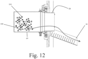
- Fig. 12 shows the transfer of material 100 from container 69 into the interior of the chamber, the direction of travel shown by the arrow.
- the protective member is deployed and overlies the ring of concern thus avoiding contamination.
- Fig. 13 shows an assembly 200 having a passive beta port 202 and an active alpha port 204, the passive and the active are complementarily shaped such that they can engage with one another and have features of that described hereinabove.
- Lying between the ports 202, 204 is a transfer module 206 comprising a chamber which has at one end the alpha port and at the other a connector for mating with a conventional isolator chamber 208 or the like.
- the advantage of the module is to enable existing systems to benefit from the advantages associated with the present invention.
- Extending between the transfer module and the isolator chamber is a chute 210 which is connectable to the protective member 212 when in its deployed configuration to facilitate through passage of material therethrough.
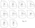
- Figs. 14 a to j show schematically the various configurations of the assembly 200 to open and close the alpha and beta ports to facilitate the movement of material into the chamber and the movement of the two doors of the alpha and beta port when connected 220.
- the arrows show the direction of movement of the various components of the system during use.
Landscapes
- Health & Medical Sciences (AREA)
- Clinical Laboratory Science (AREA)
- Chemical & Material Sciences (AREA)
- Chemical Kinetics & Catalysis (AREA)
- Engineering & Computer Science (AREA)
- Mechanical Engineering (AREA)
- Accommodation For Nursing Or Treatment Tables (AREA)
- Apparatus For Disinfection Or Sterilisation (AREA)
- Clamps And Clips (AREA)
- Devices For Use In Laboratory Experiments (AREA)
- Quick-Acting Or Multi-Walled Pipe Joints (AREA)
- Coating Apparatus (AREA)
Claims (10)
- Extern betätigtes Alpha-/Beta-Anschlusssystem (10), umfassend eine Alpha-Anschlussbaugruppe (12) und eine Beta-Anschlussbaugruppe (14), wobeia) die Alpha-Anschlussbaugruppe (12) Folgendes umfasst:i. einen Flansch, der an einer Umhüllung fixierbar ist und einen Anschluss definiert;ii. eine Klappe, die mit dem Flansch verbindbar ist, wenn sie in einer geschlossenen Konfiguration ist, so dass der Anschluss geschlossen ist, wobei die Klappe in eine offene Konfiguration bewegbar ist, in welcher der Anschluss offen ist;b) eine Beta-Anschlussbaugruppe Folgendes umfasst:i) einen Flansch (16), der an einem Übertragungsbehälter fixierbar ist, um das zu übertragende Material zu enthalten, wobei der Flansch einen Anschluss definiert;ii) eine Klappe (18), die mit dem Flansch in einer geschlossenen Konfiguration verbindbar ist, die von einer geschlossenen Konfiguration, in der die Klappe dichtend mit dem Flansch in Eingriff steht und der Anschluss geschlossen ist, und in eine zweite offene Konfiguration, in der die Klappe von dem Flansch verschoben ist und der Anschluss offen ist, bewegbar ist;wobei, wenn in der zweiten offenen Konfiguration, die Klappe mit der Klappe (50) des Alpha-Anschlusses verbunden ist, so dass beide Klappen bewegt werden können, um die Übertragung von Material durch die Anschlüsse zu ermöglichen,und wobei,der Alpha- und/oder Beta-Anschluss ein Schutzelement (28) umfasst, das sich zwischen einer ausgefahrenen und einer verstauten Konfiguration bewegen kann, und wobei, wenn der erste und der Alpha- und Beta-Anschluss dichtend miteinander in Eingriff stehen, sich das Schutzelement (28) von seiner verstauten Konfiguration in seine ausgefahrene Konfiguration bewegen kann, sodass es die Verbindungsstelle zwischen der ersten und der zweiten Flanschbaugruppe überlagert und den Durchgang von Material dadurch zulässt, während das übertragene Material vor einer möglichen Kontamination von der Verbindungsstelle geschützt wird,wobei der Beta-Anschluss (14) das Schutzelement (28) umfasst,das eine Manschette (26) umfasst, und wobei die Manschette aus einem flexiblen Material hergestellt ist, um es der Manschette zu ermöglichen, eine Bewegung des Schutzelements von einer ersten verstauten Konfiguration zuzulassen, wodurch das Schutzelement (28) die Verbindungsstelle zwischen dem Alpha- und Beta-Anschluss (12, 14) nicht überlagert und hinter der Klappe (18) des Betas zurückgehalten werden kann, wenn die Klappe in ihrer geschlossenen Konfiguration und Bewegung in eine eingesetzte, ausgefahrenen Konfiguration in Eingriff steht, wodurch das Schutzelement die Verbindungsstelle zwischen dem Alpha- und Beta-Anschluss (12, 14) überlagern kann, und;wobei die flexible Wand (38) Mittel zum Bestimmen des Verformungsgrades der Wand (38) aufweist, wenn sie von der verstauten in die eingesetzte Konfiguration bewegt wird; und wobei das Mittel ringförmige Wandverdickungen an vorbestimmten Positionen umfasst und;wobei der Beta-Anschluss (12) ein Schutzelementbetätigungsmittel umfasst, das mit dem Schutzelement, das außerhalb des Innenvolumens der Isoliersperrkammer betreibbar ist, so dass das Schutzelement (28) zwischen seinen Konfigurationen bewegt werden kann, wirkverbunden ist.
- System nach Anspruch 1, wobei der Alpha-/Beta-Anschluss konfiguriert ist, um außerhalb des Innenvolumens der Isoliersperrkammer betrieben zu werden; und/oder wobei wahlweise der Alpha- und der Beta-Anschluss miteinander in Eingriff bringbar sind und dadurch über ein Passmittel (47, 58) gesichert sind; und wobei wahlweise das Passmittel ein Steckelement (58), das an einem von dem Alpha- oder Beta-Anschluss angeordnet ist und ein Buchsenelement (47) umfassen kann, das auf dem anderen angeordnet ist; und wobei wahlweise das Steckelement (58) einen Bajonettverschluss (58) und die Buchse (47) eine komplementär geformte Aussparung (47) umfasst, oder wobei das Passmittel eine Steckverbindung umfasst; und wobei wahlweise das Steckelement an dem Beta-Anschluss (14) angeordnet ist und das Buchsenelement an dem Alpha-Anschluss (12) angeordnet ist; und wobei wahlweise jeder Anschluss eine Vielzahl von Passelementen umfasst; und wobei wahlweise die Passelemente an den Klappen zu den Alpha- und Beta-Anschlüssen angeordnet sind.
- System nach einem der Ansprüche 1 oder 2, wobei das Schutzelement (28) einen Trichter (30) umfasst, der geformt ist, um die Verbindungsstelle zwischen dem Alpha und dem Beta zu überlagern und den Durchgang von Material dadurch zuzulassen.
- System nach einem der vorstehenden Ansprüche, wobei der Alpha-Anschluss (14) Klappenbetätigungsmitteln (54) zum Steuern des Öffnens und des Schließens der Anschlüsse zugeordnet ist; und wobei wahlweise das Klappenbetätigungsmittel (54) mit der Klappe (50) des Alpha-Anschlusses wirkverbunden ist; und wobei wahlweise das Klappenbetätigungsmittel (54) zu einer Übersetzungsbewegung der Klappe und zu einer Drehbewegung der Klappe fähig ist; und wobei wahlweise das Klappenbetätigungsmittel (54) mit einem gekrümmten Arm (62) wirkverbunden ist, an dem die Klappe an einem Ende montiert ist und an dem das andere Ende an einer Schulter (64) montiert ist, wobei die Schulter (64) zu einer Übersetzungsbewegung fähig ist, um die Klappe von dem Alpha-Anschluss (14) nach hinten zu bewegen und zu einer Drehbewegung fähig ist, um die Klappe (50) von dem Alpha-Anschluss (14) weg zu schwenken, sodass die Klappe den Anschluss nicht behindert, und wobei wahlweise ein Betätigungsmittel (54) verwendet wird, um die Alpha-Anschlussklappe übersetzend zu bewegen und/oder zu drehen; und wobei wahlweise, wenn sich die zwei Klappen in der offenen Konfiguration befinden, so dass keine Klappe den Anschluss behindert, die Anschlussklappen um einen Abstand von dem Anschluss getrennt sind, der ausreicht, um das Risiko eines Kontakts des Produkts, das mit den Rändern und Dichtungen der Klappen übertragen wird, zu minimieren.
- System nach einem der Ansprüche 1 bis 4, wobei der Alpha-Anschluss (14) einer Rutsche (66) zugeordnet ist, um Material entlang des Alpha-Anschlusses (14) zu leiten, wenn dieses in die Kammer übertragen wird; und/oder wobei wahlweise der Beta-Anschluss (12) ein Mittel umfasst, um die Klappe (18) dauerhaft in Eingriff zu bringen, sobald die Klappe geöffnet wurde (18) und dann in ihrer geschlossenen Konfiguration erneut mit dem Anschluss (12) in Eingriff gebracht wird.
- System nach einem der vorstehenden Ansprüche, umfassend ein Verriegelungsmittel (70) zum dauerhaften Verriegeln der Beta-Anschlussklappe (18), wenn die Klappe mit dem Beta-Anschluss (12) erneut in Eingriff gebracht wird; und wahlweise aufweisend ein Anzeigemittel, um anzugeben, wann das Verriegelungsmittel die Klappe des Beta-Anschlusses verriegelt hat; und wobei wahlweise das Anzeigemittel eine visuelle Anzeige umfasst; und wobei wahlweise das Verriegelungsmittel (70) automatisch vorbereitet wird, wenn die Beta-Anschlussklappe (18) zuerst von dem Beta-Anschlussflansch (16) freigegeben wird.
- System nach einem der vorstehenden Ansprüche, ferner umfassend ein Sterilisationsmodul, das zum Überlagern der Klappe (18, 50) eines Anschlusses und zum Bilden einer Kammer dazwischen fähig ist, in die Sterilisationsfluid eintreten kann; und/oder wobei die Baugruppe eine Zwischenkonfiguration umfasst, wobei die Anschlüsse (12, 14) dichtend mit den Klappen verbunden sind, die voneinander beabstandet sind und eine Kammer dazwischen bilden, wobei die Kammer Mittel zum Einführen von Sterilisationsmitteln zur Dekontamination der Außenoberflächen der Klappen und/oder ihrer Dichtungen aufweist; und wobei das Sterilisationsmittel eines oder mehrere von UV, Ozon, Dampf, dampfförmigem Wasserstoffperoxid, Chlordioxid und Formaldehyd umfasst.
- Verfahren zum Übertragen von Material zwischen einem ersten und einem zweiten eingeschlossenen Volumen, das die Verwendung eines Systems nach einem der Ansprüche 1 bis 7 umfasst, wobei das Schutzelement (28) zwischen seiner verstauten und eingesetzten Konfigurationen durch Mittel außerhalb des ersten und des zweiten Volumens bewegt wird, wobei das Verfahren Folgendes umfasst:1) Ineingriffbringen der Alpha- (14) und Beta-Anschlüsse (12), sodass die Alpha- und Beta-Anschlussklappen (18, 50) in einer geschlossenen Konfiguration sind und die Flansche miteinander in Eingriff stehen und eine Dichtung dazwischen aufweisen;2) Bewegen der Klappen (18, 50) in ihre offene Konfiguration, um den Durchgang von Material dadurch zuzulassen;3) Bewegen des Schutzelements (28) von seiner verstauten in seine ausgefahrene Konfiguration, so dass es die Verbindungsstelle zwischen dem ersten und dem zweiten Flansch überlagert und den Durchgang von Material durch den ersten und den zweiten Anschluss zulässt, während das dadurch fließende Material vor einer möglichen Kontamination von der Verbindungsstelle geschützt wird.
- Verfahren nach Anspruch 8, wobei das Bewegen des Schutzelements von seiner verstauten in seine ausgefahrene Konfiguration durch externes Betätigen des Schutzelementbetätigungsmittels erreicht wird.
- Verfahren nach Anspruch 8 oder 9, ferner umfassend den nachfolgenden Schritt des erneuten Ineingriffbringens der zweiten Anschlussklappe (18) mit dem zweiten Flansch und Verriegeln der Klappe mit dem Flansch, sodass die Klappe nicht mehr von dem zweiten Flansch außer Eingriff gebracht werden kann; und wobei wahlweise das Verriegelungsmittel (70) automatisch vorbereitet wird, wenn die zweite Anschlussklappe (18) zuerst von dem zweiten Flansch freigegeben wird.
Priority Applications (2)
| Application Number | Priority Date | Filing Date | Title |
|---|---|---|---|
| PL16770540.9T PL3347127T5 (pl) | 2015-09-08 | 2016-08-26 | Urządzenie przenoszące |
| SI201630774T SI3347127T2 (sl) | 2015-09-08 | 2016-08-26 | Prenosna naprava |
Applications Claiming Priority (2)
| Application Number | Priority Date | Filing Date | Title |
|---|---|---|---|
| GB1515865.2A GB2542123A (en) | 2015-09-08 | 2015-09-08 | Transfer device |
| PCT/GB2016/052659 WO2017042536A1 (en) | 2015-09-08 | 2016-08-26 | Transfer device |
Publications (3)
| Publication Number | Publication Date |
|---|---|
| EP3347127A1 EP3347127A1 (de) | 2018-07-18 |
| EP3347127B1 EP3347127B1 (de) | 2020-02-26 |
| EP3347127B2 true EP3347127B2 (de) | 2023-06-07 |
Family
ID=54345909
Family Applications (1)
| Application Number | Title | Priority Date | Filing Date |
|---|---|---|---|
| EP16770540.9A Active EP3347127B2 (de) | 2015-09-08 | 2016-08-26 | Übertragungsvorrichtung |
Country Status (18)
| Country | Link |
|---|---|
| US (1) | US10722892B2 (de) |
| EP (1) | EP3347127B2 (de) |
| JP (1) | JP7043394B2 (de) |
| KR (1) | KR102115682B1 (de) |
| CN (1) | CN108025302B (de) |
| AU (1) | AU2016319571B2 (de) |
| BR (1) | BR112018004575B1 (de) |
| CA (1) | CA2997677C (de) |
| ES (1) | ES2793299T5 (de) |
| GB (2) | GB2542123A (de) |
| MY (1) | MY196724A (de) |
| NZ (1) | NZ740519A (de) |
| PH (1) | PH12018500514B1 (de) |
| PL (1) | PL3347127T5 (de) |
| PT (1) | PT3347127T (de) |
| RU (1) | RU2722029C9 (de) |
| SI (1) | SI3347127T2 (de) |
| WO (1) | WO2017042536A1 (de) |
Families Citing this family (18)
| Publication number | Priority date | Publication date | Assignee | Title |
|---|---|---|---|---|
| DE102016009678A1 (de) * | 2016-08-09 | 2018-02-15 | Atec Pharmatechnik Gmbh | Verfahren und Behälter zum Transport und zur Übergabe von sterilem schüttfähigem Gut in einen Isolator |
| JP7008330B2 (ja) * | 2018-06-11 | 2022-02-10 | 株式会社エムアイアイ | 組み合わせ医薬品の製造方法および製造装置 |
| CN110508332B (zh) * | 2019-08-21 | 2021-12-07 | 中国航空制造技术研究院 | 一种组合式柔性净气舱装置 |
| DE102019007042A1 (de) * | 2019-10-10 | 2021-04-15 | Atec Pharmatechnik Gmbh | Behälter und Verfahren zum Transport von sterilem Gut und zur Entnahme in einem Isolator, sowie Kombination aus Isolator und angedocktem Behälter |
| GB2590434B (en) * | 2019-12-17 | 2022-02-16 | Oribiotech Ltd | An Apparatus |
| FR3105191B1 (fr) * | 2019-12-20 | 2021-11-19 | Abc Transfer | Arrangement de porte comprenant une goulotte de transfert a deux axes de rotation |
| CN111658792B (zh) * | 2020-05-26 | 2021-08-31 | 青岛市妇女儿童医院 | 一种避免交叉感染的医疗器械传递箱 |
| DE102021201569A1 (de) * | 2021-02-18 | 2022-08-18 | Castus GmbH & Co. KG | beta-Behälter für ein alpha-beta-Portsystem |
| FR3120559B1 (fr) * | 2021-03-15 | 2023-11-24 | Getinge La Calhene | Systeme de transfert pour enceinte etanche comportant un dispositif de connexion etanche avec un volume clos |
| FR3123638B1 (fr) * | 2021-06-07 | 2023-06-02 | Getinge La Calhene | Dispositif de tranfert pour enceinte etanche comportant une partie deformable |
| JP1723868S (ja) * | 2021-12-23 | 2022-09-02 | 移送ドア | |
| FR3139723A1 (fr) | 2022-09-21 | 2024-03-22 | Lab'science | Sas de décontamination |
| DE102022131808A1 (de) * | 2022-11-30 | 2024-06-06 | Groninger & Co. Gmbh | Funktionselement, Beta-Behältersystem, Transfersystem und Barrieresystem |
| USD1098480S1 (en) * | 2023-04-26 | 2025-10-14 | Stabilus Motion Controls Gmbh | Handle for a rapid transfer port |
| USD1098481S1 (en) * | 2023-04-26 | 2025-10-14 | Stabilus Motion Controls Gmbh | Handle for a rapid transfer port |
| FR3151304B1 (fr) * | 2023-07-20 | 2025-10-17 | Getinge Life Science France | dispositif de connexion étanche pour transfert d’objets à déversement amélioré |
| WO2025017126A1 (fr) * | 2023-07-20 | 2025-01-23 | Getinge Life Science France | Dispositif de connexion étanche pour transfert d'objets à déversement amélioré |
| KR102744699B1 (ko) * | 2024-08-02 | 2024-12-19 | 바이온팩 주식회사 | 이송장치 |
Citations (4)
| Publication number | Priority date | Publication date | Assignee | Title |
|---|---|---|---|---|
| EP0662373A1 (de) † | 1994-01-07 | 1995-07-12 | Delaware Capital Formation Inc. | Verschlossenes Transfertsystem |
| US5853207A (en) † | 1994-06-17 | 1998-12-29 | I D C - Isolateur Denominateur Commun | Device for joining and sealing together two enclosures isolated from an external environment |
| US20050168117A1 (en) † | 2001-12-14 | 2005-08-04 | Jean-Yves Porret | Protective device for a sterile chamber |
| US20070095426A1 (en) † | 2005-03-15 | 2007-05-03 | Isolateur Denominateur Commun | Flexible container with incorporated guide member |
Family Cites Families (21)
| Publication number | Priority date | Publication date | Assignee | Title |
|---|---|---|---|---|
| GB8818268D0 (en) | 1988-08-01 | 1988-09-07 | Secr Defence | Transfer system for sealable enclosure |
| US5681025A (en) * | 1995-01-20 | 1997-10-28 | Kohler Co. | Motor operated butterfly valve with a multi-function seal |
| DE19526510C2 (de) * | 1995-07-20 | 1997-05-15 | Waldner Gmbh & Co Hermann | Automatisches Transfersystem |
| GB9707641D0 (en) * | 1997-04-15 | 1997-06-04 | Matcon R & D Ltd | Apparatus and system for handling material |
| GB9818536D0 (en) * | 1998-08-25 | 1998-10-21 | Matcon R & D Ltd | Material handling apparatus |
| FR2787235B1 (fr) * | 1998-12-11 | 2001-01-19 | Becton Dickinson France | Dispositif de liaison de portes entre deux enceintes isolees du milieu exterieur |
| JP2003534100A (ja) * | 2000-05-26 | 2003-11-18 | ピュアパルス テクノロジーズ インコーポレイテッド | パルス化多色光通り抜け殺菌装置 |
| DE60204825T2 (de) * | 2001-07-25 | 2006-05-18 | Ivan Semenenko | Füllverschluss für Behälter |
| US6575397B1 (en) * | 2002-04-25 | 2003-06-10 | Kimberly-Clark Worldwide, Inc. | Dispenser for sheet material |
| GB0605531D0 (en) | 2006-03-20 | 2006-04-26 | Powder Systems Ltd | Improvements Relating To Valves |
| EP2162039B1 (de) | 2007-06-28 | 2014-11-26 | Nestec S.A. | Container zur lagerung und entladung von schüttgut |
| KR100949721B1 (ko) * | 2008-01-18 | 2010-03-29 | 한국원자력연구원 | 방사성 물질 운반을 위한 핫셀 도어와 컨테이너 접속시스템 및 접속 방법 |
| EP2100836A1 (de) * | 2008-03-14 | 2009-09-16 | Valvengineering S.R.L. | Lösbare Verbindungsvorrichtung zum Übertragen von Material zwischen zwei Behältern |
| US20100084045A1 (en) * | 2008-10-03 | 2010-04-08 | Adams Richard H | Sterile liquid transfer port |
| GB0902324D0 (en) * | 2009-02-12 | 2009-04-01 | Powder Systems Ltd | Improvements relating to valves |
| FR2952988B1 (fr) | 2009-11-23 | 2012-02-03 | Sartorius Stedim Aseptics | Perfectionnements a la jonction etanche et au transfert etanche entre deux enceintes en vue d'un transfert aseptique entre elles. |
| US20120153610A1 (en) * | 2010-12-20 | 2012-06-21 | Thomas Mitchel Young | Aseptic transfer port |
| FR2978363B1 (fr) * | 2011-07-29 | 2013-09-13 | Sartorius Stedim Aseptics | Conteneur pour le transfert aseptique d'un produit biopharmaceutique. |
| US8950624B2 (en) * | 2011-12-29 | 2015-02-10 | Giuseppe Sacca | Externally operated alpha port system for use with a rapid transfer port |
| GB201203559D0 (en) * | 2012-02-29 | 2012-04-11 | Chargepoint Technology Ltd | Improvements relating to valves |
| JP5415647B1 (ja) * | 2013-08-21 | 2014-02-12 | 株式会社ミウラ | スプリット弁 |
-
2015
- 2015-09-08 GB GB1515865.2A patent/GB2542123A/en not_active Withdrawn
-
2016
- 2016-08-25 PH PH1/2018/500514A patent/PH12018500514B1/en unknown
- 2016-08-25 GB GB1614494.1A patent/GB2538898A/en not_active Withdrawn
- 2016-08-26 ES ES16770540T patent/ES2793299T5/es active Active
- 2016-08-26 SI SI201630774T patent/SI3347127T2/sl unknown
- 2016-08-26 US US15/757,609 patent/US10722892B2/en active Active
- 2016-08-26 MY MYPI2018000328A patent/MY196724A/en unknown
- 2016-08-26 RU RU2018107986A patent/RU2722029C9/ru active
- 2016-08-26 JP JP2018512275A patent/JP7043394B2/ja active Active
- 2016-08-26 WO PCT/GB2016/052659 patent/WO2017042536A1/en not_active Ceased
- 2016-08-26 EP EP16770540.9A patent/EP3347127B2/de active Active
- 2016-08-26 KR KR1020187009911A patent/KR102115682B1/ko active Active
- 2016-08-26 PL PL16770540.9T patent/PL3347127T5/pl unknown
- 2016-08-26 CN CN201680051796.0A patent/CN108025302B/zh active Active
- 2016-08-26 CA CA2997677A patent/CA2997677C/en active Active
- 2016-08-26 BR BR112018004575-6A patent/BR112018004575B1/pt active IP Right Grant
- 2016-08-26 AU AU2016319571A patent/AU2016319571B2/en active Active
- 2016-08-26 NZ NZ740519A patent/NZ740519A/en unknown
- 2016-08-26 PT PT167705409T patent/PT3347127T/pt unknown
Patent Citations (4)
| Publication number | Priority date | Publication date | Assignee | Title |
|---|---|---|---|---|
| EP0662373A1 (de) † | 1994-01-07 | 1995-07-12 | Delaware Capital Formation Inc. | Verschlossenes Transfertsystem |
| US5853207A (en) † | 1994-06-17 | 1998-12-29 | I D C - Isolateur Denominateur Commun | Device for joining and sealing together two enclosures isolated from an external environment |
| US20050168117A1 (en) † | 2001-12-14 | 2005-08-04 | Jean-Yves Porret | Protective device for a sterile chamber |
| US20070095426A1 (en) † | 2005-03-15 | 2007-05-03 | Isolateur Denominateur Commun | Flexible container with incorporated guide member |
Also Published As
Similar Documents
| Publication | Publication Date | Title |
|---|---|---|
| EP3347127B2 (de) | Übertragungsvorrichtung | |
| EP1996840B1 (de) | Kupplungsanordnung | |
| CN102388246B (zh) | 分离阀 | |
| US8950624B2 (en) | Externally operated alpha port system for use with a rapid transfer port | |
| CN102575974A (zh) | 取样装置 | |
| US9816618B2 (en) | Valve assembly | |
| KR20120028266A (ko) | 커넥터 조립체, 커넥터 조립체를 포함하는 유체 시스템, 및 유체 연결을 이루기 위한 방법 | |
| KR20140110833A (ko) | 제어된 환경 인클로저 내에 유체 경로를 보호 및 보호 해제하는 방법 | |
| CN115103743A (zh) | 允许两个封闭体积之间的密封转移的门组合件 | |
| JP2024523219A (ja) | 変形可能部分を備える密閉されたエンクロージャのための移送デバイス | |
| CN100507338C (zh) | 以防止污染的密封方式互连细长元件端部的方法和装置 | |
| ES2711345T3 (es) | Dispositivo de conexión estanca entre dos confinamientos | |
| US20240142033A1 (en) | Transfer device |
Legal Events
| Date | Code | Title | Description |
|---|---|---|---|
| STAA | Information on the status of an ep patent application or granted ep patent |
Free format text: STATUS: THE INTERNATIONAL PUBLICATION HAS BEEN MADE |
|
| PUAI | Public reference made under article 153(3) epc to a published international application that has entered the european phase |
Free format text: ORIGINAL CODE: 0009012 |
|
| STAA | Information on the status of an ep patent application or granted ep patent |
Free format text: STATUS: REQUEST FOR EXAMINATION WAS MADE |
|
| 17P | Request for examination filed |
Effective date: 20180320 |
|
| AK | Designated contracting states |
Kind code of ref document: A1 Designated state(s): AL AT BE BG CH CY CZ DE DK EE ES FI FR GB GR HR HU IE IS IT LI LT LU LV MC MK MT NL NO PL PT RO RS SE SI SK SM TR |
|
| AX | Request for extension of the european patent |
Extension state: BA ME |
|
| DAV | Request for validation of the european patent (deleted) | ||
| DAX | Request for extension of the european patent (deleted) | ||
| STAA | Information on the status of an ep patent application or granted ep patent |
Free format text: STATUS: EXAMINATION IS IN PROGRESS |
|
| 17Q | First examination report despatched |
Effective date: 20181212 |
|
| GRAP | Despatch of communication of intention to grant a patent |
Free format text: ORIGINAL CODE: EPIDOSNIGR1 |
|
| STAA | Information on the status of an ep patent application or granted ep patent |
Free format text: STATUS: GRANT OF PATENT IS INTENDED |
|
| INTG | Intention to grant announced |
Effective date: 20190730 |
|
| GRAS | Grant fee paid |
Free format text: ORIGINAL CODE: EPIDOSNIGR3 |
|
| GRAA | (expected) grant |
Free format text: ORIGINAL CODE: 0009210 |
|
| STAA | Information on the status of an ep patent application or granted ep patent |
Free format text: STATUS: THE PATENT HAS BEEN GRANTED |
|
| AK | Designated contracting states |
Kind code of ref document: B1 Designated state(s): AL AT BE BG CH CY CZ DE DK EE ES FI FR GB GR HR HU IE IS IT LI LT LU LV MC MK MT NL NO PL PT RO RS SE SI SK SM TR |
|
| REG | Reference to a national code |
Ref country code: GB Ref legal event code: FG4D |
|
| REG | Reference to a national code |
Ref country code: CH Ref legal event code: EP |
|
| REG | Reference to a national code |
Ref country code: AT Ref legal event code: REF Ref document number: 1236976 Country of ref document: AT Kind code of ref document: T Effective date: 20200315 |
|
| REG | Reference to a national code |
Ref country code: IE Ref legal event code: FG4D |
|
| REG | Reference to a national code |
Ref country code: DE Ref legal event code: R096 Ref document number: 602016030643 Country of ref document: DE |
|
| REG | Reference to a national code |
Ref country code: PT Ref legal event code: SC4A Ref document number: 3347127 Country of ref document: PT Date of ref document: 20200528 Kind code of ref document: T Free format text: AVAILABILITY OF NATIONAL TRANSLATION Effective date: 20200521 |
|
| REG | Reference to a national code |
Ref country code: CH Ref legal event code: NV Representative=s name: NOVAGRAAF INTERNATIONAL SA, CH |
|
| REG | Reference to a national code |
Ref country code: SE Ref legal event code: TRGR |
|
| PG25 | Lapsed in a contracting state [announced via postgrant information from national office to epo] |
Ref country code: NO Free format text: LAPSE BECAUSE OF FAILURE TO SUBMIT A TRANSLATION OF THE DESCRIPTION OR TO PAY THE FEE WITHIN THE PRESCRIBED TIME-LIMIT Effective date: 20200526 Ref country code: FI Free format text: LAPSE BECAUSE OF FAILURE TO SUBMIT A TRANSLATION OF THE DESCRIPTION OR TO PAY THE FEE WITHIN THE PRESCRIBED TIME-LIMIT Effective date: 20200226 Ref country code: RS Free format text: LAPSE BECAUSE OF FAILURE TO SUBMIT A TRANSLATION OF THE DESCRIPTION OR TO PAY THE FEE WITHIN THE PRESCRIBED TIME-LIMIT Effective date: 20200226 |
|
| REG | Reference to a national code |
Ref country code: NL Ref legal event code: MP Effective date: 20200226 |
|
| REG | Reference to a national code |
Ref country code: LT Ref legal event code: MG4D |
|
| PG25 | Lapsed in a contracting state [announced via postgrant information from national office to epo] |
Ref country code: IS Free format text: LAPSE BECAUSE OF FAILURE TO SUBMIT A TRANSLATION OF THE DESCRIPTION OR TO PAY THE FEE WITHIN THE PRESCRIBED TIME-LIMIT Effective date: 20200626 Ref country code: BG Free format text: LAPSE BECAUSE OF FAILURE TO SUBMIT A TRANSLATION OF THE DESCRIPTION OR TO PAY THE FEE WITHIN THE PRESCRIBED TIME-LIMIT Effective date: 20200526 Ref country code: GR Free format text: LAPSE BECAUSE OF FAILURE TO SUBMIT A TRANSLATION OF THE DESCRIPTION OR TO PAY THE FEE WITHIN THE PRESCRIBED TIME-LIMIT Effective date: 20200527 Ref country code: LV Free format text: LAPSE BECAUSE OF FAILURE TO SUBMIT A TRANSLATION OF THE DESCRIPTION OR TO PAY THE FEE WITHIN THE PRESCRIBED TIME-LIMIT Effective date: 20200226 Ref country code: HR Free format text: LAPSE BECAUSE OF FAILURE TO SUBMIT A TRANSLATION OF THE DESCRIPTION OR TO PAY THE FEE WITHIN THE PRESCRIBED TIME-LIMIT Effective date: 20200226 |
|
| PG25 | Lapsed in a contracting state [announced via postgrant information from national office to epo] |
Ref country code: NL Free format text: LAPSE BECAUSE OF FAILURE TO SUBMIT A TRANSLATION OF THE DESCRIPTION OR TO PAY THE FEE WITHIN THE PRESCRIBED TIME-LIMIT Effective date: 20200226 |
|
| PG25 | Lapsed in a contracting state [announced via postgrant information from national office to epo] |
Ref country code: LT Free format text: LAPSE BECAUSE OF FAILURE TO SUBMIT A TRANSLATION OF THE DESCRIPTION OR TO PAY THE FEE WITHIN THE PRESCRIBED TIME-LIMIT Effective date: 20200226 Ref country code: SK Free format text: LAPSE BECAUSE OF FAILURE TO SUBMIT A TRANSLATION OF THE DESCRIPTION OR TO PAY THE FEE WITHIN THE PRESCRIBED TIME-LIMIT Effective date: 20200226 Ref country code: RO Free format text: LAPSE BECAUSE OF FAILURE TO SUBMIT A TRANSLATION OF THE DESCRIPTION OR TO PAY THE FEE WITHIN THE PRESCRIBED TIME-LIMIT Effective date: 20200226 Ref country code: CZ Free format text: LAPSE BECAUSE OF FAILURE TO SUBMIT A TRANSLATION OF THE DESCRIPTION OR TO PAY THE FEE WITHIN THE PRESCRIBED TIME-LIMIT Effective date: 20200226 Ref country code: DK Free format text: LAPSE BECAUSE OF FAILURE TO SUBMIT A TRANSLATION OF THE DESCRIPTION OR TO PAY THE FEE WITHIN THE PRESCRIBED TIME-LIMIT Effective date: 20200226 Ref country code: SM Free format text: LAPSE BECAUSE OF FAILURE TO SUBMIT A TRANSLATION OF THE DESCRIPTION OR TO PAY THE FEE WITHIN THE PRESCRIBED TIME-LIMIT Effective date: 20200226 Ref country code: EE Free format text: LAPSE BECAUSE OF FAILURE TO SUBMIT A TRANSLATION OF THE DESCRIPTION OR TO PAY THE FEE WITHIN THE PRESCRIBED TIME-LIMIT Effective date: 20200226 |
|
| REG | Reference to a national code |
Ref country code: ES Ref legal event code: FG2A Ref document number: 2793299 Country of ref document: ES Kind code of ref document: T3 Effective date: 20201113 Ref country code: DE Ref legal event code: R026 Ref document number: 602016030643 Country of ref document: DE |
|
| REG | Reference to a national code |
Ref country code: AT Ref legal event code: MK05 Ref document number: 1236976 Country of ref document: AT Kind code of ref document: T Effective date: 20200226 |
|
| PLBI | Opposition filed |
Free format text: ORIGINAL CODE: 0009260 |
|
| PLAX | Notice of opposition and request to file observation + time limit sent |
Free format text: ORIGINAL CODE: EPIDOSNOBS2 |
|
| 26 | Opposition filed |
Opponent name: ATEC PHARMATECHNIK GMBH Effective date: 20201113 |
|
| PG25 | Lapsed in a contracting state [announced via postgrant information from national office to epo] |
Ref country code: AT Free format text: LAPSE BECAUSE OF FAILURE TO SUBMIT A TRANSLATION OF THE DESCRIPTION OR TO PAY THE FEE WITHIN THE PRESCRIBED TIME-LIMIT Effective date: 20200226 |
|
| PG25 | Lapsed in a contracting state [announced via postgrant information from national office to epo] |
Ref country code: MC Free format text: LAPSE BECAUSE OF FAILURE TO SUBMIT A TRANSLATION OF THE DESCRIPTION OR TO PAY THE FEE WITHIN THE PRESCRIBED TIME-LIMIT Effective date: 20200226 |
|
| PLBB | Reply of patent proprietor to notice(s) of opposition received |
Free format text: ORIGINAL CODE: EPIDOSNOBS3 |
|
| PG25 | Lapsed in a contracting state [announced via postgrant information from national office to epo] |
Ref country code: LU Free format text: LAPSE BECAUSE OF NON-PAYMENT OF DUE FEES Effective date: 20200826 |
|
| PG25 | Lapsed in a contracting state [announced via postgrant information from national office to epo] |
Ref country code: TR Free format text: LAPSE BECAUSE OF FAILURE TO SUBMIT A TRANSLATION OF THE DESCRIPTION OR TO PAY THE FEE WITHIN THE PRESCRIBED TIME-LIMIT Effective date: 20200226 Ref country code: MT Free format text: LAPSE BECAUSE OF FAILURE TO SUBMIT A TRANSLATION OF THE DESCRIPTION OR TO PAY THE FEE WITHIN THE PRESCRIBED TIME-LIMIT Effective date: 20200226 Ref country code: CY Free format text: LAPSE BECAUSE OF FAILURE TO SUBMIT A TRANSLATION OF THE DESCRIPTION OR TO PAY THE FEE WITHIN THE PRESCRIBED TIME-LIMIT Effective date: 20200226 |
|
| PG25 | Lapsed in a contracting state [announced via postgrant information from national office to epo] |
Ref country code: MK Free format text: LAPSE BECAUSE OF FAILURE TO SUBMIT A TRANSLATION OF THE DESCRIPTION OR TO PAY THE FEE WITHIN THE PRESCRIBED TIME-LIMIT Effective date: 20200226 Ref country code: AL Free format text: LAPSE BECAUSE OF FAILURE TO SUBMIT A TRANSLATION OF THE DESCRIPTION OR TO PAY THE FEE WITHIN THE PRESCRIBED TIME-LIMIT Effective date: 20200226 |
|
| PUAH | Patent maintained in amended form |
Free format text: ORIGINAL CODE: 0009272 |
|
| STAA | Information on the status of an ep patent application or granted ep patent |
Free format text: STATUS: PATENT MAINTAINED AS AMENDED |
|
| 27A | Patent maintained in amended form |
Effective date: 20230607 |
|
| AK | Designated contracting states |
Kind code of ref document: B2 Designated state(s): AL AT BE BG CH CY CZ DE DK EE ES FI FR GB GR HR HU IE IS IT LI LT LU LV MC MK MT NL NO PL PT RO RS SE SI SK SM TR |
|
| REG | Reference to a national code |
Ref country code: DE Ref legal event code: R102 Ref document number: 602016030643 Country of ref document: DE |
|
| P01 | Opt-out of the competence of the unified patent court (upc) registered |
Effective date: 20230522 |
|
| REG | Reference to a national code |
Ref country code: SE Ref legal event code: RPEO |
|
| REG | Reference to a national code |
Ref country code: ES Ref legal event code: DC2A Ref document number: 2793299 Country of ref document: ES Kind code of ref document: T5 Effective date: 20231120 |
|
| PGFP | Annual fee paid to national office [announced via postgrant information from national office to epo] |
Ref country code: PL Payment date: 20250608 Year of fee payment: 10 |
|
| PGFP | Annual fee paid to national office [announced via postgrant information from national office to epo] |
Ref country code: IE Payment date: 20250610 Year of fee payment: 10 |
|
| PGFP | Annual fee paid to national office [announced via postgrant information from national office to epo] |
Ref country code: SI Payment date: 20250624 Year of fee payment: 10 |
|
| PGFP | Annual fee paid to national office [announced via postgrant information from national office to epo] |
Ref country code: ES Payment date: 20250902 Year of fee payment: 10 Ref country code: PT Payment date: 20250820 Year of fee payment: 10 |
|
| PGFP | Annual fee paid to national office [announced via postgrant information from national office to epo] |
Ref country code: DE Payment date: 20250702 Year of fee payment: 10 |
|
| PGFP | Annual fee paid to national office [announced via postgrant information from national office to epo] |
Ref country code: IT Payment date: 20250722 Year of fee payment: 10 |
|
| PGFP | Annual fee paid to national office [announced via postgrant information from national office to epo] |
Ref country code: BE Payment date: 20250703 Year of fee payment: 10 Ref country code: GB Payment date: 20250703 Year of fee payment: 10 |
|
| PGFP | Annual fee paid to national office [announced via postgrant information from national office to epo] |
Ref country code: FR Payment date: 20250703 Year of fee payment: 10 |
|
| PGFP | Annual fee paid to national office [announced via postgrant information from national office to epo] |
Ref country code: CH Payment date: 20250901 Year of fee payment: 10 Ref country code: SE Payment date: 20250702 Year of fee payment: 10 |