EP3346252A1 - Dispositif de pré-traitement pour l'analyse de gaz - Google Patents
Dispositif de pré-traitement pour l'analyse de gaz Download PDFInfo
- Publication number
- EP3346252A1 EP3346252A1 EP16844329.9A EP16844329A EP3346252A1 EP 3346252 A1 EP3346252 A1 EP 3346252A1 EP 16844329 A EP16844329 A EP 16844329A EP 3346252 A1 EP3346252 A1 EP 3346252A1
- Authority
- EP
- European Patent Office
- Prior art keywords
- gas
- collecting portion
- flow path
- temperature
- gas flow
- Prior art date
- Legal status (The legal status is an assumption and is not a legal conclusion. Google has not performed a legal analysis and makes no representation as to the accuracy of the status listed.)
- Granted
Links
- 238000004868 gas analysis Methods 0.000 title claims abstract description 76
- 238000007781 pre-processing Methods 0.000 title claims abstract description 47
- 239000007789 gas Substances 0.000 claims abstract description 201
- 238000001816 cooling Methods 0.000 claims abstract description 81
- 239000004020 conductor Substances 0.000 claims abstract description 42
- 239000012535 impurity Substances 0.000 claims abstract description 17
- CURLTUGMZLYLDI-UHFFFAOYSA-N Carbon dioxide Chemical compound O=C=O CURLTUGMZLYLDI-UHFFFAOYSA-N 0.000 claims description 31
- 239000001569 carbon dioxide Substances 0.000 claims description 25
- 229910002092 carbon dioxide Inorganic materials 0.000 claims description 25
- 229910001868 water Inorganic materials 0.000 claims description 20
- NBIIXXVUZAFLBC-UHFFFAOYSA-N Phosphoric acid Chemical compound OP(O)(O)=O NBIIXXVUZAFLBC-UHFFFAOYSA-N 0.000 claims description 16
- XLYOFNOQVPJJNP-UHFFFAOYSA-N water Substances O XLYOFNOQVPJJNP-UHFFFAOYSA-N 0.000 claims description 10
- 229910000147 aluminium phosphate Inorganic materials 0.000 claims description 8
- 238000007711 solidification Methods 0.000 claims description 5
- 230000008023 solidification Effects 0.000 claims description 5
- 229910052738 indium Inorganic materials 0.000 claims description 4
- APFVFJFRJDLVQX-UHFFFAOYSA-N indium atom Chemical compound [In] APFVFJFRJDLVQX-UHFFFAOYSA-N 0.000 claims description 4
- 238000000034 method Methods 0.000 abstract description 18
- IJGRMHOSHXDMSA-UHFFFAOYSA-N Atomic nitrogen Chemical compound N#N IJGRMHOSHXDMSA-UHFFFAOYSA-N 0.000 description 26
- 239000007788 liquid Substances 0.000 description 14
- 229910052757 nitrogen Inorganic materials 0.000 description 13
- 239000011521 glass Substances 0.000 description 9
- VTYYLEPIZMXCLO-UHFFFAOYSA-L Calcium carbonate Chemical compound [Ca+2].[O-]C([O-])=O VTYYLEPIZMXCLO-UHFFFAOYSA-L 0.000 description 8
- LFQSCWFLJHTTHZ-UHFFFAOYSA-N Ethanol Chemical compound CCO LFQSCWFLJHTTHZ-UHFFFAOYSA-N 0.000 description 4
- 238000004458 analytical method Methods 0.000 description 4
- 229910000019 calcium carbonate Inorganic materials 0.000 description 4
- 238000010586 diagram Methods 0.000 description 4
- 229910001256 stainless steel alloy Inorganic materials 0.000 description 4
- 238000000859 sublimation Methods 0.000 description 4
- 230000008022 sublimation Effects 0.000 description 4
- 229910002089 NOx Inorganic materials 0.000 description 3
- 238000000642 dynamic headspace extraction Methods 0.000 description 3
- 238000004817 gas chromatography Methods 0.000 description 3
- 238000010438 heat treatment Methods 0.000 description 3
- 239000001307 helium Substances 0.000 description 3
- 229910052734 helium Inorganic materials 0.000 description 3
- SWQJXJOGLNCZEY-UHFFFAOYSA-N helium atom Chemical compound [He] SWQJXJOGLNCZEY-UHFFFAOYSA-N 0.000 description 3
- 238000003780 insertion Methods 0.000 description 3
- 230000037431 insertion Effects 0.000 description 3
- 229910001220 stainless steel Inorganic materials 0.000 description 3
- 239000010935 stainless steel Substances 0.000 description 3
- 210000000988 bone and bone Anatomy 0.000 description 2
- 235000011089 carbon dioxide Nutrition 0.000 description 2
- 238000003795 desorption Methods 0.000 description 2
- 239000011261 inert gas Substances 0.000 description 2
- 238000009434 installation Methods 0.000 description 2
- 238000005259 measurement Methods 0.000 description 2
- 239000005416 organic matter Substances 0.000 description 2
- 229910052815 sulfur oxide Inorganic materials 0.000 description 2
- OKTJSMMVPCPJKN-UHFFFAOYSA-N Carbon Chemical compound [C] OKTJSMMVPCPJKN-UHFFFAOYSA-N 0.000 description 1
- BVKZGUZCCUSVTD-UHFFFAOYSA-L Carbonate Chemical compound [O-]C([O-])=O BVKZGUZCCUSVTD-UHFFFAOYSA-L 0.000 description 1
- UFHFLCQGNIYNRP-UHFFFAOYSA-N Hydrogen Chemical compound [H][H] UFHFLCQGNIYNRP-UHFFFAOYSA-N 0.000 description 1
- VYPSYNLAJGMNEJ-UHFFFAOYSA-N Silicium dioxide Chemical compound O=[Si]=O VYPSYNLAJGMNEJ-UHFFFAOYSA-N 0.000 description 1
- QVGXLLKOCUKJST-UHFFFAOYSA-N atomic oxygen Chemical compound [O] QVGXLLKOCUKJST-UHFFFAOYSA-N 0.000 description 1
- 239000012159 carrier gas Substances 0.000 description 1
- 230000006835 compression Effects 0.000 description 1
- 238000007906 compression Methods 0.000 description 1
- 239000012141 concentrate Substances 0.000 description 1
- 238000007796 conventional method Methods 0.000 description 1
- 238000002290 gas chromatography-mass spectrometry Methods 0.000 description 1
- 229910002804 graphite Inorganic materials 0.000 description 1
- 239000010439 graphite Substances 0.000 description 1
- 239000001257 hydrogen Substances 0.000 description 1
- 229910052739 hydrogen Inorganic materials 0.000 description 1
- 238000009413 insulation Methods 0.000 description 1
- 238000001307 laser spectroscopy Methods 0.000 description 1
- 238000012986 modification Methods 0.000 description 1
- 230000004048 modification Effects 0.000 description 1
- 239000001301 oxygen Substances 0.000 description 1
- 229910052760 oxygen Inorganic materials 0.000 description 1
- 238000007493 shaping process Methods 0.000 description 1
- 239000007787 solid Substances 0.000 description 1
- 239000000126 substance Substances 0.000 description 1
Images


Classifications
-
- G—PHYSICS
- G01—MEASURING; TESTING
- G01N—INVESTIGATING OR ANALYSING MATERIALS BY DETERMINING THEIR CHEMICAL OR PHYSICAL PROPERTIES
- G01N1/00—Sampling; Preparing specimens for investigation
- G01N1/02—Devices for withdrawing samples
- G01N1/22—Devices for withdrawing samples in the gaseous state
- G01N1/2226—Sampling from a closed space, e.g. food package, head space
-
- G—PHYSICS
- G01—MEASURING; TESTING
- G01N—INVESTIGATING OR ANALYSING MATERIALS BY DETERMINING THEIR CHEMICAL OR PHYSICAL PROPERTIES
- G01N1/00—Sampling; Preparing specimens for investigation
-
- G—PHYSICS
- G01—MEASURING; TESTING
- G01N—INVESTIGATING OR ANALYSING MATERIALS BY DETERMINING THEIR CHEMICAL OR PHYSICAL PROPERTIES
- G01N1/00—Sampling; Preparing specimens for investigation
- G01N1/02—Devices for withdrawing samples
- G01N1/22—Devices for withdrawing samples in the gaseous state
-
- G—PHYSICS
- G01—MEASURING; TESTING
- G01N—INVESTIGATING OR ANALYSING MATERIALS BY DETERMINING THEIR CHEMICAL OR PHYSICAL PROPERTIES
- G01N30/00—Investigating or analysing materials by separation into components using adsorption, absorption or similar phenomena or using ion-exchange, e.g. chromatography or field flow fractionation
- G01N30/02—Column chromatography
- G01N30/04—Preparation or injection of sample to be analysed
- G01N30/06—Preparation
- G01N30/12—Preparation by evaporation
-
- G—PHYSICS
- G01—MEASURING; TESTING
- G01N—INVESTIGATING OR ANALYSING MATERIALS BY DETERMINING THEIR CHEMICAL OR PHYSICAL PROPERTIES
- G01N30/00—Investigating or analysing materials by separation into components using adsorption, absorption or similar phenomena or using ion-exchange, e.g. chromatography or field flow fractionation
- G01N30/02—Column chromatography
- G01N30/04—Preparation or injection of sample to be analysed
- G01N30/16—Injection
- G01N30/20—Injection using a sampling valve
-
- G—PHYSICS
- G01—MEASURING; TESTING
- G01N—INVESTIGATING OR ANALYSING MATERIALS BY DETERMINING THEIR CHEMICAL OR PHYSICAL PROPERTIES
- G01N31/00—Investigating or analysing non-biological materials by the use of the chemical methods specified in the subgroup; Apparatus specially adapted for such methods
-
- G—PHYSICS
- G01—MEASURING; TESTING
- G01N—INVESTIGATING OR ANALYSING MATERIALS BY DETERMINING THEIR CHEMICAL OR PHYSICAL PROPERTIES
- G01N33/00—Investigating or analysing materials by specific methods not covered by groups G01N1/00 - G01N31/00
- G01N33/0004—Gaseous mixtures, e.g. polluted air
- G01N33/0009—General constructional details of gas analysers, e.g. portable test equipment
- G01N33/0027—General constructional details of gas analysers, e.g. portable test equipment concerning the detector
- G01N33/0036—General constructional details of gas analysers, e.g. portable test equipment concerning the detector specially adapted to detect a particular component
- G01N33/0047—Organic compounds
-
- G—PHYSICS
- G01—MEASURING; TESTING
- G01N—INVESTIGATING OR ANALYSING MATERIALS BY DETERMINING THEIR CHEMICAL OR PHYSICAL PROPERTIES
- G01N30/00—Investigating or analysing materials by separation into components using adsorption, absorption or similar phenomena or using ion-exchange, e.g. chromatography or field flow fractionation
- G01N30/02—Column chromatography
- G01N2030/022—Column chromatography characterised by the kind of separation mechanism
- G01N2030/025—Gas chromatography
-
- G—PHYSICS
- G01—MEASURING; TESTING
- G01N—INVESTIGATING OR ANALYSING MATERIALS BY DETERMINING THEIR CHEMICAL OR PHYSICAL PROPERTIES
- G01N30/00—Investigating or analysing materials by separation into components using adsorption, absorption or similar phenomena or using ion-exchange, e.g. chromatography or field flow fractionation
- G01N30/02—Column chromatography
- G01N30/04—Preparation or injection of sample to be analysed
- G01N30/06—Preparation
- G01N30/12—Preparation by evaporation
- G01N2030/121—Preparation by evaporation cooling; cold traps
Definitions
- the present invention relates to a preprocessing apparatus for gas analysis operable to introduce a target gas to be analyzed into a gas analysis device.
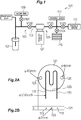
- FIG. 9 is a schematic diagram illustrating an example configuration of a preprocessing apparatus for gas analysis according to the related art.
- a preprocessing apparatus 1 for gas analysis separates a target gas to be analyzed and gases of impurities from a mixed gas, and introduces the target gas into a gas analysis device.
- the preprocessing apparatus 1 for gas analysis mainly includes a gas flow path 3, a cooling portion 5, and a plurality of valves V1 to V5 that serve as gas flow path connection changing means for changing the gas flow path.
- the gas flow path 3 is constituted from a glass pipe having a pipe diameter of 1 cm to 1.5 cm, and connected to a gas generating source 7, a vacuum pump 9, and a gas analysis device 11 via the valves.
- a collecting portion 13 configured to collect the gases of impurities is provided in the gas flow path 3 between the valves V2 and V3.
- a bellows 15 and a pressure gauge 17 are provided between the collecting portion 13 and the gas analysis device 11. The target gas is introduced into the gas analysis device 11 at a constant pressure by the bellows 15.
- the cooling portion 5 cools the collecting portion 13, and is formed from a Dewar vessel 19 and a cryogen put in the Dewar vessel 19.
- the gas generating source 7 is configured such that phosphoric acid can be dropped into a container that contains a sample. Phosphoric acid is dropped onto the sample to generate a mixed gas.
- a mixed gas containing carbon dioxide (CO 2 ), water (H 2 O), and a minute amount of other gases is generated.
- CO 2 is the target gas to be analyzed.
- H 2 O is the gas of impurities.
- the gas generating source 7 may cause a reaction between a different sample and a different substance. Outside air may be directly introduced to analyze a target gas contained in the air.
- the vacuum pump 9 evacuates the gas flow path 3 to establish a vacuum (low to middle vacuum) state.
- the collecting portion 13 is formed by shaping a glass pipe into a U-shape or a spiral shape, and immersed in the cryogen put in the Dewar vessel 19 for cooling.
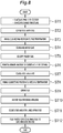
- Fig. 10 is a flowchart according to the related art of a process in which the target gas to be analyzed is introduced into the gas analysis device 11.
- the gas flow path 3 is evacuated using the vacuum pump 9, with only the valve V5 being closed, to establish a vacuum (low to middle vacuum) state (step ST1) .
- the valves V1 and V3 are closed (step ST2), and the collecting portion 13 is immersed in a first Dewar vessel 19A filled with liquid nitrogen (at about -196°C) which serves as a first cryogen (step ST3).
- step ST4 When the gas generating source 7 generates a gas (mixed gas) (step ST4), a pressure gradient is caused between the gas generating source 7 and the collecting portion 13 which has been cooled by the liquid nitrogen, and the generated mixed gas is collected in the collecting portion 13 and solidified (step ST5). Specifically, CO 2 is solidified into dry ice, and H 2 O is solidified into ice. The minute amount of other gases that cannot be collected at this point is removed utilizing the vacuum pump 9 with the valve V1 being opened (step ST6). After that, the valves V1 and V2 are closed (step ST7).
- the first Dewar vessel 19A is replaced with a second Dewar vessel 19B filled with a second cryogen (at about -80°C) prepared by adding ethanol to liquid nitrogen (step ST8).
- the temperature of the collecting portion 13 is gradually raised to about -80°C, and CO 2 alone is gasified with H 2 O remaining ice.
- the valve V3 is opened (step ST9) to measure the amount of generated CO 2 using the pressure gauge 17.
- the volume of the bellows 15 is adjusted so as to establish a predetermined pressure (step ST10) .
- the valves V3 and V4 are closed, and the valve V5 is opened (step ST11) .
- the target gas to be analyzed is diffused or scattered to feed the target gas to the gas analysis device 11 (step ST12).
- Non-Patent Document 1 is a common method of preprocessing performed before the target gas to be analyzed is introduced into the gas analysis device.
- Non-Patent Document 2 a stainless steel pipe having a pipe diameter of about 0.6 cm is used for gas flow path.
- a sample set in a thermal desorption portion is heated under an inert gas (helium), a generated gas component is adsorbed by a trap pipe (collecting portion) that has been cooled.
- the trap pipe is rapidly heated, and the adsorbed gas is introduced for gas chromatography or the like.
- the trap pipe (collecting portion) is cooled using liquid nitrogen (Non-Patent Document 3).
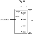
- Non-Patent Document 1 The biggest problem with the method described in Non-Patent Document 1 is that a cryogen comprised of liquid nitrogen and a cryogen comprised of liquid nitrogen and ethanol must be used at room temperature. This is because the cryogen is gradually evaporated at room temperature and needs to be always replenished since the liquid surface in the Dewar vessel becomes lower if the cryogen is left as it is. According to a measurement by the inventor, as illustrated in Fig. 11 , the temperature of the cryogen in the Dewar vessel (having a height of 22 cm and a diameter of 8.5 cm) tends to be higher at lower portions and on the outer side than at upper portions and on the inner side, respectively. Thus, it is difficult to keep the temperature of the liquid nitrogen constant.
- the collecting portion 13 In addition, it is necessary to immerse the collecting portion 13 in the cryogen in the Dewar vessel 19, and therefore it is necessary to shape the collecting portion 13 so as to extend downward.
- the collecting portion 13 must have some degree of size since a glass pipe is used for the collecting portion 13.
- a concentration step is necessary to concentrate the target gas to be analyzed before the target gas is fed to the gas analysis device since the space in the glass pipe is large for the amount of the target gas to be analyzed, which makes the target gas thinner.
- the concentration step it is necessary to use liquid nitrogen as the cryogen.
- the Dewar vessel 19A is replaced with the Dewar vessel 19B, the glass pipe is exposed to room temperature, although only for a short time. Therefore, there is a risk that the mixed gas which has been solidified may be gasified, and quick replacement is required.
- Non-Patent Document 2 does not require replacement of Dewar vessels. However, the device also uses liquid nitrogen as a cryogen, and therefore has the same issues as those of Non-Patent Document 1.
- An object of the present invention is to provide a preprocessing apparatus for gas analysis that enables preprocessing for gas analysis to be performed without requiring a cryogen.
- Another object of the present invention is to provide a preprocessing apparatus for gas analysis that obtains a target gas to be analyzed that has a sufficient concentration even without performing a step of concentrating the target gas to be analyzed.
- a preprocessing apparatus for gas analysis includes, as basic components, a gas flow path including a collecting portion that is cooled in order to collect a target gas to be analyzed, and a cooling device operable to cool the collecting portion of the gas flow path.
- a preprocessing apparatus for gas analysis which separates the target gas from a mixed gas, includes: a gas flow path including a collecting portion that is cooled to a plurality of temperature levels in order to separate a target gas to be analyzed and gases of impurities from a mixed gas containing a plurality of kinds of gases; a cooling device operable to cool the collecting portion of the gas flow path to the plurality of temperature levels; and a gas flow path connection changing means for connecting the gas flow path to a vacuum pump when evacuating the gas flow path, connecting the gas flow path to a gas generating source when introducing the mixed gas into the gas flow path after the gas flow path has been evacuated, and connecting the gas flow path to a gas analysis device in order to supply the target gas, which has been separated by the collecting portion, to the gas analysis device.
- the collecting portion is cooled to a plurality of temperature levels according to the solidification temperature of the target gas.
- the collecting portion is often cooled to a plurality of temperature levels in order to separate a gas having the lowest solidification temperature, as a target gas to be analyzed, from a mixed gas containing a plurality of kinds of gases and to collect other kinds of gases other than the target gas, as gases of impurities.
- the preprocessing apparatus for gas analysis further includes a heat conductor configured to surround an outer periphery of the collecting portion.
- the cooling device includes a contact cooling section configured to contact the collecting portion to uniformly cool the collecting portion to a set temperature, and has a temperature adjusting function of adjusting a temperature of the contact cooling section to an arbitrary temperature by utilizing electrical energy.
- the collecting portion, the heat conductor, and the contact cooling section may be received in a vacuum chamber of a sealed structure, the vacuum chamber being connected to a vacuum pump and evacuated; and the vacuum chamber may have been brought into a vacuum state by the vacuum pump when the collecting portion is cooled.
- the collecting portion can be cooled without being affected by air or room temperature.
- the heat conductor contacts the contact cooling section via an indium sheet, the collecting portion can be cooled more efficiently.
- the collecting portion is preferably meanderingly arranged in the heat conductor. Further, if the collecting portion is meanderingly arranged along a cooling surface of the contact cooling section, a larger portion of the collecting portion can be cooled by the contact cooling section, thereby efficiently cooling the collecting portion. Most suitably, the collecting portion has an overall length of 5 cm or more and 15 cm or less.
- the preprocessing apparatus for gas analysis according to the present invention does not need to use liquid nitrogen, and therefore does not need to use a glass pipe. Therefore, the collecting portion can have a diameter of one-eighth of an inch (3.175 mm) or less, and further one-sixteenth of an inch (1.5875 mm) or less.
- the heat conductor is preferably insert molded including the gas pipe as an insert.
- the gas pipe and the heat conductor are unitarily formed, which enables the gas pipe as the collecting portion to be efficiently cooled.
- the heat conductor may include a heater configured to be electrically energized to generate heat. With such a heater, the collecting portion which has been cooled by the cooling device can be heated, which enables quick temperature adjustment.
- the preprocessing apparatus for gas analysis is used to introduce a target gas to be analyzed into a gas analysis device.
- the preprocessing apparatus for gas analysis can be used to remove water (H 2 O) as an impurity from a mixed gas generated by adding phosphoric acid to a sample and introducing carbon dioxide (CO 2 ) as a target gas into a gas analysis device.
- water H 2 O
- CO 2 carbon dioxide
- Fig. 1 is a schematic diagram illustrating the configuration of a preprocessing apparatus for gas analysis according to an embodiment.
- Figs. 2A and 2B are a plan view and a front view, respectively, illustrating a collecting portion and a heat conductor with the heat conductor being rendered transparent.
- Fig. 3 is a front view illustrating the configuration of a cooling portion.
- Fig. 4 is a plan view illustrating a contact cooling section of a cooling device.
- Figs. 5A, 5B, and 5C are a plan view, a front view, and a sectional view taken along line C-C, respectively, of a lower structure forming a sealed structure.
- Figs. 6A, 6B, and 6C are a plan view, a front view, and a sectional view taken along line C-C, respectively, of an upper structure forming the sealed structure.
- a preprocessing apparatus 101 for gas analysis mainly includes a gas flow path 103, a cooling portion 105, and a plurality of valves V101 to V105 that serve as gas flow path connection changing means for changing the gas flow path.
- the preprocessing apparatus 101 for gas analysis is different from the conventional preprocessing apparatus for gas analysis mainly in the configuration of a collecting portion 113 and the cooling portion 105 which cools the collecting portion 113.
- the preprocessing apparatus for gas analysis of the embodiment will be described below, focusing on the differences from the conventional preprocessing apparatuses for gas analysis. Common members are denoted by reference numerals obtained by adding 100 to the reference numerals affixed to their counterparts of the conventional preprocessing apparatus for gas analysis illustrated in Fig. 9 , and explanations of such parts are occasionally omitted.
- the gas flow path 103 of the embodiment is formed from a stainless steel alloy pipe having a pipe diameter of one-sixteenth of an inch (1.5875 mm) to one-eighth of an inch (3.175 mm), and connected to a gas generating source 107, a vacuum pump 109, and a gas analysis device 111 via valves.
- the gas flow path 103 includes a collecting portion 113 provided between the valves V102 and V103 and configured to collect gases of impurities .
- a bellows 115 and a pressure gauge 117 are provided between the collecting portion 113 and the gas analysis device 111.
- the target gas to be analyzed is introduced into the gas analysis device 111 at a constant pressure by the bellows 115.
- the collecting portion 113 of the embodiment is a gas pipe made of a stainless steel alloy illustrated in Fig. 2 .
- a pas pipe suitably has an overall length of 5 cm to 15 cm and a diameter of one-sixty-fourth of an inch (0.396875 mm) to one-eighth of an inch (3.175 mm).
- Use of such thin pipe having a small diameter can omit a step of concentrating the target gas to be analyzed, which is performed in the conventional method that uses a glass pipe having a large internal space.
- a thin pipe having a small diameter, for example, of one-sixty-fourth of an inch (0.396875 mm) to one-sixteenth of an inch (1.5875 mm) is generally used for effective introduction or feeding of the target gas as with the embodiment of the present invention.
- the present invention can be directly applied to such devices.
- the gas pipe has an overall length of 12 cm and a diameter of one-sixteenth of an inch (1.5875 mm) .
- the outer periphery of the collecting portion 113 is surrounded by a heat conductor 121 made of a stainless steel alloy.
- the collecting portion 113 is meanderingly arranged in the heat conductor 121.
- the heat conductor 121 is insert molded including the gas pipe, which is the collecting portion 113, as an insert.
- the heat conductor 121 has a temperature sensor insertion hole 123 formed therein for insertion of a temperature sensor configured to measure the temperature of the collecting portion 113.
- the heat conductor 121 also has through holes 125, 125 formed therein for fixation of the heat conductor 121 to a cooling device that will be discussed later.
- the dimensions of the respective portions are as illustrated in Fig. 2 .
- the cooling portion 105 is operable to cool the collecting portion 113, and is constituted from the heat conductor 121, a cooling device 127, and a sealed structure 129 as illustrated in Fig. 3 .
- a lower structure 139 and an upper structure 141 of the sealed structure 129 are illustrated in section.
- the cooling device 127 includes a disc-shaped contact cooling section 131 configured to contact the heat conductor 121 to uniformly cool the collecting portion 113 to a set temperature, and has a temperature adjusting function of adjusting the temperature of the contact cooling section 131 to an arbitrary temperature by utilizing electrical energy.
- the cooling device 127 is specifically a stirling cooler operable to achieve an extremely low temperature through stirling cycles including constant-volume heating, isothermal expansion, constant-volume cooling, and isothermal compression.
- a "Cryo Cooler (model name: SC-UF01)" manufactured by Twinbird Corporation is used as the cooling device 127.
- SC-UF01 can bring the contact cooling section 131 to an extremely low temperature or a cryogenic temperature lower than -200°C by utilizing electrical energy, and can finely control the temperature in units of 0.1°C.
- four screw holes 133 are formed in a cooling surface 131A of the contact cooling section 131.
- the heat conductor 121 is fixed to the contact cooling section 131 by screws 135.
- an indium sheet 137 is interposed between the heat conductor 121 and the contact cooling section 131.
- the collecting portion 113 is meanderingly arranged along the cooling surface 131A of the contact cooling section 131. With such arrangement of the collecting portion 113, a larger portion of the collecting portion 113 can be cooled by the contact cooling section 131, and the gas which passes inside the collecting portion 113 can be stabilized.
- the attitude of installation of SC-UF01 is not limited to that illustrated in Fig. 3 , and SC-UF01 may be installed in a laid state.
- Another advantage of using SC-UF01 and the collecting portion 113 is that SC-UF01 can be in an attitude that matches the location of installation. This is a difference from the conventional preprocessing method which uses a cryogen.
- the sealed structure 129 is intended to receive the collecting portion 113, the heat conductor 121, and the contact cooling section 131 of the cooling device 127.
- the contact cooling section 131 is received inside the sealed structure 129 such that a clearance of about 10 mm is provided between the outer periphery of the contact cooling section 131 and the sealed structure 129 and a clearance of about 10 mm is provided between the upper and lower surfaces of the contact cooling section 131 and the sealed structure 129 in the vertical direction.
- the space defined by such clearances allows evacuation to be completed in a short time, and enables appropriate heat insulation.
- the sealed structure 129 is constituted from two members, namely the lower structure 139 and the upper structure 141.
- the lower structure 139 has a cylindrical shape, and is provided with a flange 139A to be fixed to the cooling device 127 at one end portion and a flange 139B to be fixed to the upper structure 141 at the other end portion.
- the flange 139B is provided with two groove portions 143A and 143B configured to receive a part of a pipe that connects to the gas pipe (see Fig. 2 ) made of stainless steel and forming the collecting portion 113.
- the flange 139B has four screw holes 145 formed therein for fixation of the upper structure 141.
- the upper structure 141 is a lid-like member having an opening at one end portion and a bottom at the other end portion and configured to block the other end portion of the lower structure 139.
- a flange 141A to be fixed to the flange 139B of the lower structure 139 is provided at the opening end portion of the upper structure 141.
- the flange 141A has screw holes 147 formed therein at positions corresponding to the screw holes 145.
- a bottom portion 141B of the upper structure 141 has a vacuum pump connection hole 149 formed therein for connection to the vacuum pump when evacuating the sealed structure 129.
- a flange portion 128 ( Fig. 3 ) of the cooling device 127 and the flange 139A of the lower structure 139 are fixed to each other by a vacuum clamp (not illustrated) with an O-ring interposed therebetween, and the flange portion 139B of the lower structure 139 and the flange 141A of the upper structure 141 are fixed to each other by screws (not illustrated) with an O-ring interposed therebetween.
- the sealed structure 129 is obtained.
- the sealed structure 129 is evacuated using a vacuum pump.
- Figs. 7A and 7B illustrate an example configuration in which the heat conductor 121 is provided with a heater 122.
- a cable connected to a power source etc. is not illustrated.
- the heater 122 is a sheet-like heater, and is configured to be electrically energized to generate heat.
- the heater 122 is provided on a surface of the heat conductor 121 opposite to the surface which contacts the contact cooling section 131. It is optional whether or not to provide the heater 122.
- the heater 122 is useful if it is desirable to quickly raise the temperature of the collecting portion.
- the gas generating source 107 is configured such that phosphoric acid can be dropped into a container that contains a sample. Phosphoric acid is dropped onto the sample to generate a mixed gas.
- a mixed gas containing carbon dioxide (CO 2 ), water (H 2 O), and a minute amount of other gases is generated.
- CO 2 is the target gas to be analyzed.
- H 2 O (and the minute amount of other gases) is the gas of impurities.
- Fig. 8 is a flowchart of a process until the target gas to be analyzed is introduced into the gas analysis device 111.
- the gas flow path 103 is evacuated using the vacuum pump 109, with only the valve V105 being closed, to establish a vacuum (low to middle vacuum) state.
- the sealed structure 129 is evacuated to establish a vacuum (low to middle vacuum) state (step ST1).
- the valves V101 and V103 are closed (step ST2), and the collecting portion 113 is brought to a first temperature using the cooling device 127 (step ST3).
- the first temperature may be a temperature at which CO 2 as the target gas is solidified (a temperature lower than the sublimation point) .
- CO 2 is cooled to -196°C as in the conventional preprocessing method.
- the gas flow path 103 has been evacuated to about 0 to 5 Torr (1.013 bar to 1.019 bar), and therefore the sublimation point is slightly lower than -78.5°C that is the sublimation point at normal pressure.
- step ST4 When the gas generating source 107 generates a gas (mixed gas) (step ST4), a pressure gradient is caused between the gas generating source 107 and the collecting portion 113 which has been cooled, and the generated mixed gas is collected in the collecting portion 113 and solidified (step ST5). Specifically, CO 2 is solidified into dry ice, and H 2 O is solidified into ice. The minute amount of other gases that cannot be collected at this point is removed utilizing the vacuum pump 109 with the valve V101 being opened (step ST6). After that, the valves V101 and V102 are closed (step ST7).
- the second temperature may be a temperature around or higher than the temperature at which CO 2 is gasified (sublimation point).
- the temperature is raised to -80°C as in the conventional preprocessing method. If the heater 122 is provided, the heater 122 is actuated to quickly raise and adjust the temperature.
- CO 2 alone is gasified with H 2 O remaining in an ice state.
- valve V103 is opened (step ST9) to measure the amount of generated CO 2 using the pressure gauge 117.
- the volume of the bellows 115 is adjusted so as to achieve a predetermined pressure (step ST10).
- the valves V103 and V104 are closed and the valve V105 is opened (step ST11) .
- the target gas to be analyzed is diffused to feed the target gas to the gas analysis device 111 (step ST12).
- the collecting portion 113 in particular, can be formed from a gas pipe that is made of a stainless steel alloy and that is thin and short compared to the conventional glass pipe as discussed above. Therefore, the space in the collecting portion 113 is small, which makes it possible to make the target gas thick compared to the related art.
- the target gas having a sufficient concentration can be obtained even if the step of concentrating the target gas is not performed before the target gas is fed to the gas analysis device. As a matter of course, this does not mean to exclude the concentration step, and the concentration step may be performed depending on the analysis content or the like.
- the present invention can also be used when an organic matter is used as a sample, a silica glass pipe containing the organic matter is evacuated and then sealed to prepare a sealed pipe, the sealed pipe is burnt to generate a mixed gas containing CO 2 , water, NO x , and SO x , and NO x and SO x containing water as gases of impurities are removed.
- This method is used in a radiocarbon isotope dating method that is widely used in archeology and geology.
- the first temperature and the second temperature for the cooling device 127 may be set to-196°C and-130°C, respectively, since NO x and SO x can be trapped when cooled to -130°C.
- the target gas to be analyzed and the gases of impurities are separated from each other utilizing the solidification temperatures of the respective gases and the temperatures at which the gases are gasified from a solid state. Therefore, even if one of the gases of impurities has the lowest solidification temperature or a plurality of gases of impurities are mixed, the target gas can be extracted by setting corresponding temperature levels.
- the target gas is CO 2 in the above embodiment. If the target gas is water, the collecting portion can be cooled stepwisely to a plurality of temperature levels .
- the mixed gas is cooled to a first temperature at which CO 2 can be solidified, thereafter CO 2 is gasified at a second temperature higher than the first temperature, then CO 2 is discharged using a pump, and thereafter the temperature is raised to a third temperature of 0°C or higher to obtain only water.
- the present invention is also applicable to implement the "purge and trap” method which is used in volatile gas analysis.
- a sample set in a thermal desorption portion is heated under an inert gas (helium), and a generated gas component is adsorbed by a trap pipe (collecting portion) that has been cooled.
- the trap pipe is rapidly heated, and the adsorbed gas is introduced into a gas chromatograph for gas chromatography or the like.
- the trap pipe (collecting portion) may be cooled and heated using a device that is similar to the preprocessing apparatus for gas analysis according to the embodiment described above.
- a target gas to be analyzed is extracted, without using a cryogen.
- a target gas to be analyzed that has a sufficient concentration can be obtained even without performing a step of concentrating the target gas to be analyzed.
Landscapes
- Health & Medical Sciences (AREA)
- Life Sciences & Earth Sciences (AREA)
- Chemical & Material Sciences (AREA)
- Analytical Chemistry (AREA)
- General Health & Medical Sciences (AREA)
- Pathology (AREA)
- Immunology (AREA)
- Physics & Mathematics (AREA)
- General Physics & Mathematics (AREA)
- Biochemistry (AREA)
- Engineering & Computer Science (AREA)
- Molecular Biology (AREA)
- Biomedical Technology (AREA)
- Combustion & Propulsion (AREA)
- Medicinal Chemistry (AREA)
- Food Science & Technology (AREA)
- Sampling And Sample Adjustment (AREA)
- Investigating Or Analyzing Non-Biological Materials By The Use Of Chemical Means (AREA)
Applications Claiming Priority (2)
| Application Number | Priority Date | Filing Date | Title |
|---|---|---|---|
| JP2015176635A JP6838256B2 (ja) | 2015-09-08 | 2015-09-08 | ガス分析用前処理装置 |
| PCT/JP2016/076107 WO2017043468A1 (fr) | 2015-09-08 | 2016-09-06 | Dispositif de pré-traitement pour l'analyse de gaz |
Publications (3)
| Publication Number | Publication Date |
|---|---|
| EP3346252A1 true EP3346252A1 (fr) | 2018-07-11 |
| EP3346252A4 EP3346252A4 (fr) | 2019-06-05 |
| EP3346252B1 EP3346252B1 (fr) | 2024-01-24 |
Family
ID=58239806
Family Applications (1)
| Application Number | Title | Priority Date | Filing Date |
|---|---|---|---|
| EP16844329.9A Active EP3346252B1 (fr) | 2015-09-08 | 2016-09-06 | Dispositif de pré-traitement pour l'analyse de gaz |
Country Status (4)
| Country | Link |
|---|---|
| US (1) | US10697865B2 (fr) |
| EP (1) | EP3346252B1 (fr) |
| JP (1) | JP6838256B2 (fr) |
| WO (1) | WO2017043468A1 (fr) |
Cited By (1)
| Publication number | Priority date | Publication date | Assignee | Title |
|---|---|---|---|---|
| CN113339703A (zh) * | 2021-07-07 | 2021-09-03 | 中国科学院地质与地球物理研究所 | 一种供气调节装置、He气同位素分析系统及分析方法 |
Families Citing this family (4)
| Publication number | Priority date | Publication date | Assignee | Title |
|---|---|---|---|---|
| CN109141989A (zh) * | 2017-06-16 | 2019-01-04 | 中国石油化工股份有限公司 | 页岩解析气自动定量采样装置 |
| KR102502032B1 (ko) * | 2017-07-07 | 2023-02-21 | 주식회사 울티멈테크 | 온도 제어를 이용한 시료 분리기 및 이를 포함하는 시료 분석 장치 |
| DE102017130755A1 (de) * | 2017-12-20 | 2019-06-27 | Bilfinger Noell Gmbh | Vorrichtung zur Untersuchung einer Atmosphäre sowie Verwendung der Vorrichtung |
| CN108593820A (zh) * | 2018-05-14 | 2018-09-28 | 铜陵蓝光电子科技有限公司 | 一种固定污染源挥发性有机物(vocs)在线监测系统采样预处理器 |
Family Cites Families (10)
| Publication number | Priority date | Publication date | Assignee | Title |
|---|---|---|---|---|
| JP3651525B2 (ja) * | 1996-10-02 | 2005-05-25 | 株式会社島津製作所 | ガス試料採取装置 |
| JP2001318007A (ja) * | 2000-05-08 | 2001-11-16 | Nagoya Kogyo Univ | 温度制御装置及び方法、ガスクロマトグラフ用捕集装置及び方法、温度制御プログラムを記録したコンピュータ読み取り可能な記録媒体、温度検知装置及び方法並びに温度検知プログラムを記録したコンピュータ読み取り可能な記録媒体 |
| JP3726706B2 (ja) * | 2001-05-11 | 2005-12-14 | 日産自動車株式会社 | 試料保持装置 |
| JP4653357B2 (ja) * | 2001-08-28 | 2011-03-16 | 大陽日酸株式会社 | 金属カルボニル化合物の分析方法及び装置 |
| US6572686B1 (en) * | 2002-02-14 | 2003-06-03 | The United States Of America As Represented By The United States Department Of Energy | Apparatus for condensing and collecting hot gases |
| JP2004212075A (ja) * | 2002-12-27 | 2004-07-29 | Shimadzu Corp | 水素化物導入法による形態別分析試料前処理方法及び装置 |
| JP2004361160A (ja) * | 2003-06-03 | 2004-12-24 | Terametsukusu Kk | 呼気凝縮液採取装置 |
| JP2010008141A (ja) * | 2008-06-25 | 2010-01-14 | Canon Inc | 固体試料の作製装置、固体試料の作製方法及び試料の観察方法 |
| IT1391089B1 (it) | 2008-07-10 | 2011-11-18 | Snam Progetti | Dispositivo di campionamento in linea e metodo per l'analisi delle emissioni di composti volatili in aria |
| CN102375041B (zh) * | 2011-09-16 | 2015-03-04 | 武汉市天虹仪表有限责任公司 | 一种在线挥发性有机物分析仪及其使用方法 |
-
2015
- 2015-09-08 JP JP2015176635A patent/JP6838256B2/ja active Active
-
2016
- 2016-09-06 US US15/757,184 patent/US10697865B2/en active Active
- 2016-09-06 EP EP16844329.9A patent/EP3346252B1/fr active Active
- 2016-09-06 WO PCT/JP2016/076107 patent/WO2017043468A1/fr active Application Filing
Cited By (2)
| Publication number | Priority date | Publication date | Assignee | Title |
|---|---|---|---|---|
| CN113339703A (zh) * | 2021-07-07 | 2021-09-03 | 中国科学院地质与地球物理研究所 | 一种供气调节装置、He气同位素分析系统及分析方法 |
| CN113339703B (zh) * | 2021-07-07 | 2022-03-08 | 中国科学院地质与地球物理研究所 | 一种供气调节装置、He气同位素分析系统及分析方法 |
Also Published As
| Publication number | Publication date |
|---|---|
| JP6838256B2 (ja) | 2021-03-03 |
| US10697865B2 (en) | 2020-06-30 |
| JP2017053681A (ja) | 2017-03-16 |
| US20180252620A1 (en) | 2018-09-06 |
| EP3346252B1 (fr) | 2024-01-24 |
| WO2017043468A1 (fr) | 2017-03-16 |
| EP3346252A4 (fr) | 2019-06-05 |
Similar Documents
| Publication | Publication Date | Title |
|---|---|---|
| EP3346252B1 (fr) | Dispositif de pré-traitement pour l'analyse de gaz | |
| PT2277042T (pt) | Aparelho e método para determinação de uma composição isotópica de hidrogénio não permutável e átomos de deutério em amostras de etanol | |
| Dublyansky et al. | Hydrogen and oxygen isotopes of water from inclusions in minerals: design of a new crushing system and on‐line continuous‐flow isotope ratio mass spectrometric analysis | |
| EP2361384A1 (fr) | Four de chromatographe en phase gazeuse | |
| KR20100089486A (ko) | 가스 상 물질의 저온 농축 시스템에 적용되는 개선된 시료 전처리 유닛 | |
| Brand et al. | Automated simultaneous measurement of the δ13C and δ2H values of methane and the δ13C and δ18O values of carbon dioxide in flask air samples using a new multi cryo‐trap/gas chromatography/isotope ratio mass spectrometry system | |
| EP2520930A1 (fr) | Procédé et dispositif pour mesurer la teneur en eau d'un composé contenant du fluorure d'hydrogène | |
| EP3054338A1 (fr) | Dispositif de montage pour un échantillon et procédé de retrait d'un échantillon | |
| JP2014112045A (ja) | 低温液体の組成分析方法 | |
| Hassan et al. | A multifunctional cryo-target for the external COSY experiments | |
| JP4091977B2 (ja) | フーリエ変換方式イオンサイクロトロン共鳴質量分析方法 | |
| Hirter et al. | Micro column liquid chromatography-mass spectrometry using a capillary interface | |
| KR20170059387A (ko) | 발생 가스 분석 장치 및 발생 가스 분석 방법 | |
| KR101679569B1 (ko) | 항온 실험용 온도 조절 장치 및 이를 포함하는 가스 흡착 시스템 | |
| US7520920B1 (en) | Guard columns for gas chromatographs and gas chromatograph-mass spectrometers | |
| Marchetti et al. | A controlled atmosphere cell for a Mössbauer closed-cycle refrigerator | |
| JP7286151B2 (ja) | 昇温脱離分析装置及び昇温脱離分析方法 | |
| WO2013084948A1 (fr) | Contenant, procédé et dispositif de craquage en phase vapeur, et procédé et dispositif d'analyse | |
| JPH03152438A (ja) | 2つのチャンバの間において流体サンプルを転送するシステム/方法、ならびにガスクロマトグラフィに対する同システム/方法の適用 | |
| EP3259575B1 (fr) | Technique de régulation de la température de cellules pour échantillon d'un polarimètre | |
| DE102021112581B4 (de) | Vorrichtung zum Temperieren einer Messzelle und Verfahren zum Betreiben der Vorrichtung | |
| US3623843A (en) | Apparatus for condensing organic vapors of gas chromatographic fractions | |
| Uhl et al. | AMS measurements from microgram to milligram | |
| KR102502032B1 (ko) | 온도 제어를 이용한 시료 분리기 및 이를 포함하는 시료 분석 장치 | |
| JP3713057B2 (ja) | 質量分析装置における気体導入装置 |
Legal Events
| Date | Code | Title | Description |
|---|---|---|---|
| STAA | Information on the status of an ep patent application or granted ep patent |
Free format text: STATUS: THE INTERNATIONAL PUBLICATION HAS BEEN MADE |
|
| PUAI | Public reference made under article 153(3) epc to a published international application that has entered the european phase |
Free format text: ORIGINAL CODE: 0009012 |
|
| STAA | Information on the status of an ep patent application or granted ep patent |
Free format text: STATUS: REQUEST FOR EXAMINATION WAS MADE |
|
| 17P | Request for examination filed |
Effective date: 20180328 |
|
| AK | Designated contracting states |
Kind code of ref document: A1 Designated state(s): AL AT BE BG CH CY CZ DE DK EE ES FI FR GB GR HR HU IE IS IT LI LT LU LV MC MK MT NL NO PL PT RO RS SE SI SK SM TR |
|
| AX | Request for extension of the european patent |
Extension state: BA ME |
|
| DAV | Request for validation of the european patent (deleted) | ||
| DAX | Request for extension of the european patent (deleted) | ||
| A4 | Supplementary search report drawn up and despatched |
Effective date: 20190507 |
|
| RIC1 | Information provided on ipc code assigned before grant |
Ipc: G01N 1/00 20060101ALI20190426BHEP Ipc: G01N 33/00 20060101ALI20190426BHEP Ipc: G01N 30/12 20060101ALI20190426BHEP Ipc: G01N 1/22 20060101AFI20190426BHEP Ipc: G01N 31/00 20060101ALI20190426BHEP Ipc: G01N 30/20 20060101ALI20190426BHEP |
|
| STAA | Information on the status of an ep patent application or granted ep patent |
Free format text: STATUS: EXAMINATION IS IN PROGRESS |
|
| STAA | Information on the status of an ep patent application or granted ep patent |
Free format text: STATUS: EXAMINATION IS IN PROGRESS |
|
| 17Q | First examination report despatched |
Effective date: 20211102 |
|
| GRAP | Despatch of communication of intention to grant a patent |
Free format text: ORIGINAL CODE: EPIDOSNIGR1 |
|
| STAA | Information on the status of an ep patent application or granted ep patent |
Free format text: STATUS: GRANT OF PATENT IS INTENDED |
|
| INTG | Intention to grant announced |
Effective date: 20230519 |
|
| RIN1 | Information on inventor provided before grant (corrected) |
Inventor name: SAKAI, SABURO |
|
| GRAJ | Information related to disapproval of communication of intention to grant by the applicant or resumption of examination proceedings by the epo deleted |
Free format text: ORIGINAL CODE: EPIDOSDIGR1 |
|
| STAA | Information on the status of an ep patent application or granted ep patent |
Free format text: STATUS: EXAMINATION IS IN PROGRESS |
|
| GRAS | Grant fee paid |
Free format text: ORIGINAL CODE: EPIDOSNIGR3 |
|
| STAA | Information on the status of an ep patent application or granted ep patent |
Free format text: STATUS: GRANT OF PATENT IS INTENDED |
|
| GRAP | Despatch of communication of intention to grant a patent |
Free format text: ORIGINAL CODE: EPIDOSNIGR1 |
|
| INTC | Intention to grant announced (deleted) | ||
| INTG | Intention to grant announced |
Effective date: 20231017 |
|
| RIN1 | Information on inventor provided before grant (corrected) |
Inventor name: SAKAI, SABURO |
|
| GRAA | (expected) grant |
Free format text: ORIGINAL CODE: 0009210 |
|
| STAA | Information on the status of an ep patent application or granted ep patent |
Free format text: STATUS: THE PATENT HAS BEEN GRANTED |
|
| AK | Designated contracting states |
Kind code of ref document: B1 Designated state(s): AL AT BE BG CH CY CZ DE DK EE ES FI FR GB GR HR HU IE IS IT LI LT LU LV MC MK MT NL NO PL PT RO RS SE SI SK SM TR |
|
| REG | Reference to a national code |
Ref country code: GB Ref legal event code: FG4D |
|
| REG | Reference to a national code |
Ref country code: CH Ref legal event code: EP |
|
| REG | Reference to a national code |
Ref country code: IE Ref legal event code: FG4D |
|
| REG | Reference to a national code |
Ref country code: DE Ref legal event code: R096 Ref document number: 602016085517 Country of ref document: DE |
|
| REG | Reference to a national code |
Ref country code: LT Ref legal event code: MG9D |
|
| REG | Reference to a national code |
Ref country code: NL Ref legal event code: MP Effective date: 20240124 |
|
| PG25 | Lapsed in a contracting state [announced via postgrant information from national office to epo] |
Ref country code: NL Free format text: LAPSE BECAUSE OF FAILURE TO SUBMIT A TRANSLATION OF THE DESCRIPTION OR TO PAY THE FEE WITHIN THE PRESCRIBED TIME-LIMIT Effective date: 20240124 |
|
| PG25 | Lapsed in a contracting state [announced via postgrant information from national office to epo] |
Ref country code: NL Free format text: LAPSE BECAUSE OF FAILURE TO SUBMIT A TRANSLATION OF THE DESCRIPTION OR TO PAY THE FEE WITHIN THE PRESCRIBED TIME-LIMIT Effective date: 20240124 |
|
| PG25 | Lapsed in a contracting state [announced via postgrant information from national office to epo] |
Ref country code: IS Free format text: LAPSE BECAUSE OF FAILURE TO SUBMIT A TRANSLATION OF THE DESCRIPTION OR TO PAY THE FEE WITHIN THE PRESCRIBED TIME-LIMIT Effective date: 20240524 |
|
| PG25 | Lapsed in a contracting state [announced via postgrant information from national office to epo] |
Ref country code: LT Free format text: LAPSE BECAUSE OF FAILURE TO SUBMIT A TRANSLATION OF THE DESCRIPTION OR TO PAY THE FEE WITHIN THE PRESCRIBED TIME-LIMIT Effective date: 20240124 |
|
| PG25 | Lapsed in a contracting state [announced via postgrant information from national office to epo] |
Ref country code: GR Free format text: LAPSE BECAUSE OF FAILURE TO SUBMIT A TRANSLATION OF THE DESCRIPTION OR TO PAY THE FEE WITHIN THE PRESCRIBED TIME-LIMIT Effective date: 20240425 |
|
| REG | Reference to a national code |
Ref country code: AT Ref legal event code: MK05 Ref document number: 1652527 Country of ref document: AT Kind code of ref document: T Effective date: 20240124 |
|
| PG25 | Lapsed in a contracting state [announced via postgrant information from national office to epo] |
Ref country code: RS Free format text: LAPSE BECAUSE OF FAILURE TO SUBMIT A TRANSLATION OF THE DESCRIPTION OR TO PAY THE FEE WITHIN THE PRESCRIBED TIME-LIMIT Effective date: 20240424 Ref country code: HR Free format text: LAPSE BECAUSE OF FAILURE TO SUBMIT A TRANSLATION OF THE DESCRIPTION OR TO PAY THE FEE WITHIN THE PRESCRIBED TIME-LIMIT Effective date: 20240124 |
|
| PG25 | Lapsed in a contracting state [announced via postgrant information from national office to epo] |
Ref country code: ES Free format text: LAPSE BECAUSE OF FAILURE TO SUBMIT A TRANSLATION OF THE DESCRIPTION OR TO PAY THE FEE WITHIN THE PRESCRIBED TIME-LIMIT Effective date: 20240124 |
|
| PG25 | Lapsed in a contracting state [announced via postgrant information from national office to epo] |
Ref country code: AT Free format text: LAPSE BECAUSE OF FAILURE TO SUBMIT A TRANSLATION OF THE DESCRIPTION OR TO PAY THE FEE WITHIN THE PRESCRIBED TIME-LIMIT Effective date: 20240124 |
|
| PG25 | Lapsed in a contracting state [announced via postgrant information from national office to epo] |
Ref country code: RS Free format text: LAPSE BECAUSE OF FAILURE TO SUBMIT A TRANSLATION OF THE DESCRIPTION OR TO PAY THE FEE WITHIN THE PRESCRIBED TIME-LIMIT Effective date: 20240424 Ref country code: NO Free format text: LAPSE BECAUSE OF FAILURE TO SUBMIT A TRANSLATION OF THE DESCRIPTION OR TO PAY THE FEE WITHIN THE PRESCRIBED TIME-LIMIT Effective date: 20240424 Ref country code: LT Free format text: LAPSE BECAUSE OF FAILURE TO SUBMIT A TRANSLATION OF THE DESCRIPTION OR TO PAY THE FEE WITHIN THE PRESCRIBED TIME-LIMIT Effective date: 20240124 Ref country code: IS Free format text: LAPSE BECAUSE OF FAILURE TO SUBMIT A TRANSLATION OF THE DESCRIPTION OR TO PAY THE FEE WITHIN THE PRESCRIBED TIME-LIMIT Effective date: 20240524 Ref country code: HR Free format text: LAPSE BECAUSE OF FAILURE TO SUBMIT A TRANSLATION OF THE DESCRIPTION OR TO PAY THE FEE WITHIN THE PRESCRIBED TIME-LIMIT Effective date: 20240124 Ref country code: GR Free format text: LAPSE BECAUSE OF FAILURE TO SUBMIT A TRANSLATION OF THE DESCRIPTION OR TO PAY THE FEE WITHIN THE PRESCRIBED TIME-LIMIT Effective date: 20240425 Ref country code: FI Free format text: LAPSE BECAUSE OF FAILURE TO SUBMIT A TRANSLATION OF THE DESCRIPTION OR TO PAY THE FEE WITHIN THE PRESCRIBED TIME-LIMIT Effective date: 20240124 Ref country code: ES Free format text: LAPSE BECAUSE OF FAILURE TO SUBMIT A TRANSLATION OF THE DESCRIPTION OR TO PAY THE FEE WITHIN THE PRESCRIBED TIME-LIMIT Effective date: 20240124 Ref country code: BG Free format text: LAPSE BECAUSE OF FAILURE TO SUBMIT A TRANSLATION OF THE DESCRIPTION OR TO PAY THE FEE WITHIN THE PRESCRIBED TIME-LIMIT Effective date: 20240124 Ref country code: AT Free format text: LAPSE BECAUSE OF FAILURE TO SUBMIT A TRANSLATION OF THE DESCRIPTION OR TO PAY THE FEE WITHIN THE PRESCRIBED TIME-LIMIT Effective date: 20240124 |
|
| PG25 | Lapsed in a contracting state [announced via postgrant information from national office to epo] |
Ref country code: PL Free format text: LAPSE BECAUSE OF FAILURE TO SUBMIT A TRANSLATION OF THE DESCRIPTION OR TO PAY THE FEE WITHIN THE PRESCRIBED TIME-LIMIT Effective date: 20240124 Ref country code: PT Free format text: LAPSE BECAUSE OF FAILURE TO SUBMIT A TRANSLATION OF THE DESCRIPTION OR TO PAY THE FEE WITHIN THE PRESCRIBED TIME-LIMIT Effective date: 20240524 |
|
| PG25 | Lapsed in a contracting state [announced via postgrant information from national office to epo] |
Ref country code: SE Free format text: LAPSE BECAUSE OF FAILURE TO SUBMIT A TRANSLATION OF THE DESCRIPTION OR TO PAY THE FEE WITHIN THE PRESCRIBED TIME-LIMIT Effective date: 20240124 Ref country code: PT Free format text: LAPSE BECAUSE OF FAILURE TO SUBMIT A TRANSLATION OF THE DESCRIPTION OR TO PAY THE FEE WITHIN THE PRESCRIBED TIME-LIMIT Effective date: 20240524 Ref country code: PL Free format text: LAPSE BECAUSE OF FAILURE TO SUBMIT A TRANSLATION OF THE DESCRIPTION OR TO PAY THE FEE WITHIN THE PRESCRIBED TIME-LIMIT Effective date: 20240124 Ref country code: LV Free format text: LAPSE BECAUSE OF FAILURE TO SUBMIT A TRANSLATION OF THE DESCRIPTION OR TO PAY THE FEE WITHIN THE PRESCRIBED TIME-LIMIT Effective date: 20240124 |