EP3345871A1 - Method for purifying a liquid - Google Patents
Method for purifying a liquid Download PDFInfo
- Publication number
- EP3345871A1 EP3345871A1 EP16842406.7A EP16842406A EP3345871A1 EP 3345871 A1 EP3345871 A1 EP 3345871A1 EP 16842406 A EP16842406 A EP 16842406A EP 3345871 A1 EP3345871 A1 EP 3345871A1
- Authority
- EP
- European Patent Office
- Prior art keywords
- liquid
- drain
- raw
- purification
- line
- Prior art date
- Legal status (The legal status is an assumption and is not a legal conclusion. Google has not performed a legal analysis and makes no representation as to the accuracy of the status listed.)
- Pending
Links
- 239000007788 liquid Substances 0.000 title claims abstract description 787
- 238000000034 method Methods 0.000 title claims abstract description 52
- 238000000746 purification Methods 0.000 claims abstract description 298
- 238000011010 flushing procedure Methods 0.000 claims abstract description 90
- 238000002156 mixing Methods 0.000 claims abstract description 59
- 239000000203 mixture Substances 0.000 claims abstract description 54
- 239000000356 contaminant Substances 0.000 claims abstract description 16
- 238000006073 displacement reaction Methods 0.000 claims description 14
- 238000009825 accumulation Methods 0.000 claims description 13
- 238000011109 contamination Methods 0.000 claims description 11
- 238000001914 filtration Methods 0.000 claims description 10
- 206010016825 Flushing Diseases 0.000 claims description 7
- XLYOFNOQVPJJNP-UHFFFAOYSA-N water Substances O XLYOFNOQVPJJNP-UHFFFAOYSA-N 0.000 abstract description 4
- 238000010612 desalination reaction Methods 0.000 abstract description 2
- 239000012528 membrane Substances 0.000 description 4
- 239000012141 concentrate Substances 0.000 description 3
- 239000012530 fluid Substances 0.000 description 3
- 238000004064 recycling Methods 0.000 description 3
- 238000004659 sterilization and disinfection Methods 0.000 description 3
- 238000004140 cleaning Methods 0.000 description 2
- 230000006378 damage Effects 0.000 description 2
- 230000007423 decrease Effects 0.000 description 2
- 238000010586 diagram Methods 0.000 description 2
- 230000000694 effects Effects 0.000 description 2
- 229940126655 NDI-034858 Drugs 0.000 description 1
- 241000290929 Nimbus Species 0.000 description 1
- 239000003651 drinking water Substances 0.000 description 1
- 235000020188 drinking water Nutrition 0.000 description 1
- 238000011049 filling Methods 0.000 description 1
- 238000012986 modification Methods 0.000 description 1
- 230000004048 modification Effects 0.000 description 1
- 239000002245 particle Substances 0.000 description 1
- 238000005192 partition Methods 0.000 description 1
- 230000000149 penetrating effect Effects 0.000 description 1
- 238000001223 reverse osmosis Methods 0.000 description 1
- 238000004904 shortening Methods 0.000 description 1
- 238000011144 upstream manufacturing Methods 0.000 description 1
Images

Classifications
-
- B—PERFORMING OPERATIONS; TRANSPORTING
- B01—PHYSICAL OR CHEMICAL PROCESSES OR APPARATUS IN GENERAL
- B01D—SEPARATION
- B01D61/00—Processes of separation using semi-permeable membranes, e.g. dialysis, osmosis or ultrafiltration; Apparatus, accessories or auxiliary operations specially adapted therefor
- B01D61/02—Reverse osmosis; Hyperfiltration ; Nanofiltration
- B01D61/12—Controlling or regulating
-
- B—PERFORMING OPERATIONS; TRANSPORTING
- B01—PHYSICAL OR CHEMICAL PROCESSES OR APPARATUS IN GENERAL
- B01D—SEPARATION
- B01D61/00—Processes of separation using semi-permeable membranes, e.g. dialysis, osmosis or ultrafiltration; Apparatus, accessories or auxiliary operations specially adapted therefor
- B01D61/02—Reverse osmosis; Hyperfiltration ; Nanofiltration
- B01D61/08—Apparatus therefor
- B01D61/081—Apparatus therefor used at home, e.g. kitchen
-
- B—PERFORMING OPERATIONS; TRANSPORTING
- B01—PHYSICAL OR CHEMICAL PROCESSES OR APPARATUS IN GENERAL
- B01D—SEPARATION
- B01D61/00—Processes of separation using semi-permeable membranes, e.g. dialysis, osmosis or ultrafiltration; Apparatus, accessories or auxiliary operations specially adapted therefor
- B01D61/02—Reverse osmosis; Hyperfiltration ; Nanofiltration
- B01D61/025—Reverse osmosis; Hyperfiltration
-
- B—PERFORMING OPERATIONS; TRANSPORTING
- B01—PHYSICAL OR CHEMICAL PROCESSES OR APPARATUS IN GENERAL
- B01D—SEPARATION
- B01D65/00—Accessories or auxiliary operations, in general, for separation processes or apparatus using semi-permeable membranes
- B01D65/02—Membrane cleaning or sterilisation ; Membrane regeneration
-
- C—CHEMISTRY; METALLURGY
- C02—TREATMENT OF WATER, WASTE WATER, SEWAGE, OR SLUDGE
- C02F—TREATMENT OF WATER, WASTE WATER, SEWAGE, OR SLUDGE
- C02F1/00—Treatment of water, waste water, or sewage
- C02F1/44—Treatment of water, waste water, or sewage by dialysis, osmosis or reverse osmosis
- C02F1/441—Treatment of water, waste water, or sewage by dialysis, osmosis or reverse osmosis by reverse osmosis
-
- B—PERFORMING OPERATIONS; TRANSPORTING
- B01—PHYSICAL OR CHEMICAL PROCESSES OR APPARATUS IN GENERAL
- B01D—SEPARATION
- B01D2311/00—Details relating to membrane separation process operations and control
- B01D2311/25—Recirculation, recycling or bypass, e.g. recirculation of concentrate into the feed
- B01D2311/252—Recirculation of concentrate
- B01D2311/2523—Recirculation of concentrate to feed side
-
- B—PERFORMING OPERATIONS; TRANSPORTING
- B01—PHYSICAL OR CHEMICAL PROCESSES OR APPARATUS IN GENERAL
- B01D—SEPARATION
- B01D2313/00—Details relating to membrane modules or apparatus
- B01D2313/50—Specific extra tanks
- B01D2313/501—Permeate storage tanks
-
- B—PERFORMING OPERATIONS; TRANSPORTING
- B01—PHYSICAL OR CHEMICAL PROCESSES OR APPARATUS IN GENERAL
- B01D—SEPARATION
- B01D2313/00—Details relating to membrane modules or apparatus
- B01D2313/50—Specific extra tanks
- B01D2313/502—Concentrate storage tanks
-
- B—PERFORMING OPERATIONS; TRANSPORTING
- B01—PHYSICAL OR CHEMICAL PROCESSES OR APPARATUS IN GENERAL
- B01D—SEPARATION
- B01D2315/00—Details relating to the membrane module operation
- B01D2315/12—Feed-and-bleed systems
-
- B—PERFORMING OPERATIONS; TRANSPORTING
- B01—PHYSICAL OR CHEMICAL PROCESSES OR APPARATUS IN GENERAL
- B01D—SEPARATION
- B01D2315/00—Details relating to the membrane module operation
- B01D2315/20—Operation control schemes defined by a periodically repeated sequence comprising filtration cycles combined with cleaning or gas supply, e.g. aeration
-
- B—PERFORMING OPERATIONS; TRANSPORTING
- B01—PHYSICAL OR CHEMICAL PROCESSES OR APPARATUS IN GENERAL
- B01D—SEPARATION
- B01D2321/00—Details relating to membrane cleaning, regeneration, sterilization or to the prevention of fouling
- B01D2321/02—Forward flushing
-
- B—PERFORMING OPERATIONS; TRANSPORTING
- B01—PHYSICAL OR CHEMICAL PROCESSES OR APPARATUS IN GENERAL
- B01D—SEPARATION
- B01D2321/00—Details relating to membrane cleaning, regeneration, sterilization or to the prevention of fouling
- B01D2321/10—Use of feed
-
- B—PERFORMING OPERATIONS; TRANSPORTING
- B01—PHYSICAL OR CHEMICAL PROCESSES OR APPARATUS IN GENERAL
- B01D—SEPARATION
- B01D2321/00—Details relating to membrane cleaning, regeneration, sterilization or to the prevention of fouling
- B01D2321/14—Use of concentrate
-
- B—PERFORMING OPERATIONS; TRANSPORTING
- B01—PHYSICAL OR CHEMICAL PROCESSES OR APPARATUS IN GENERAL
- B01D—SEPARATION
- B01D61/00—Processes of separation using semi-permeable membranes, e.g. dialysis, osmosis or ultrafiltration; Apparatus, accessories or auxiliary operations specially adapted therefor
- B01D61/02—Reverse osmosis; Hyperfiltration ; Nanofiltration
- B01D61/027—Nanofiltration
-
- C—CHEMISTRY; METALLURGY
- C02—TREATMENT OF WATER, WASTE WATER, SEWAGE, OR SLUDGE
- C02F—TREATMENT OF WATER, WASTE WATER, SEWAGE, OR SLUDGE
- C02F1/00—Treatment of water, waste water, or sewage
- C02F1/44—Treatment of water, waste water, or sewage by dialysis, osmosis or reverse osmosis
-
- C—CHEMISTRY; METALLURGY
- C02—TREATMENT OF WATER, WASTE WATER, SEWAGE, OR SLUDGE
- C02F—TREATMENT OF WATER, WASTE WATER, SEWAGE, OR SLUDGE
- C02F1/00—Treatment of water, waste water, or sewage
- C02F1/44—Treatment of water, waste water, or sewage by dialysis, osmosis or reverse osmosis
- C02F1/442—Treatment of water, waste water, or sewage by dialysis, osmosis or reverse osmosis by nanofiltration
-
- C—CHEMISTRY; METALLURGY
- C02—TREATMENT OF WATER, WASTE WATER, SEWAGE, OR SLUDGE
- C02F—TREATMENT OF WATER, WASTE WATER, SEWAGE, OR SLUDGE
- C02F2103/00—Nature of the water, waste water, sewage or sludge to be treated
- C02F2103/08—Seawater, e.g. for desalination
-
- C—CHEMISTRY; METALLURGY
- C02—TREATMENT OF WATER, WASTE WATER, SEWAGE, OR SLUDGE
- C02F—TREATMENT OF WATER, WASTE WATER, SEWAGE, OR SLUDGE
- C02F2209/00—Controlling or monitoring parameters in water treatment
- C02F2209/003—Downstream control, i.e. outlet monitoring, e.g. to check the treating agents, such as halogens or ozone, leaving the process
-
- C—CHEMISTRY; METALLURGY
- C02—TREATMENT OF WATER, WASTE WATER, SEWAGE, OR SLUDGE
- C02F—TREATMENT OF WATER, WASTE WATER, SEWAGE, OR SLUDGE
- C02F2209/00—Controlling or monitoring parameters in water treatment
- C02F2209/40—Liquid flow rate
-
- C—CHEMISTRY; METALLURGY
- C02—TREATMENT OF WATER, WASTE WATER, SEWAGE, OR SLUDGE
- C02F—TREATMENT OF WATER, WASTE WATER, SEWAGE, OR SLUDGE
- C02F2303/00—Specific treatment goals
- C02F2303/16—Regeneration of sorbents, filters
-
- Y—GENERAL TAGGING OF NEW TECHNOLOGICAL DEVELOPMENTS; GENERAL TAGGING OF CROSS-SECTIONAL TECHNOLOGIES SPANNING OVER SEVERAL SECTIONS OF THE IPC; TECHNICAL SUBJECTS COVERED BY FORMER USPC CROSS-REFERENCE ART COLLECTIONS [XRACs] AND DIGESTS
- Y02—TECHNOLOGIES OR APPLICATIONS FOR MITIGATION OR ADAPTATION AGAINST CLIMATE CHANGE
- Y02A—TECHNOLOGIES FOR ADAPTATION TO CLIMATE CHANGE
- Y02A20/00—Water conservation; Efficient water supply; Efficient water use
- Y02A20/124—Water desalination
- Y02A20/131—Reverse-osmosis
Definitions
- the invention relates to a method for purification and/or desalination of liquid, mostly water, which can be used in domestic and/or drinking water supply in residential and/or industrial environment, summer cottages and garden plots.
- a conventional liquid purification method can be implemented in a liquid purification system disclosed in patent US 6,190,558 (B01D 61/00, Nimbus Water Systems, Inc., US, publ. Feb. 20, 2001).
- the liquid purification method comprises at least one automatically initiated filtration cycle involving purification of raw liquid and flushing of liquid purification means with liquid medium, wherein in the course of the cycle the raw liquid is routed to a liquid purification unit through a raw liquid feed line.
- the raw liquid is supplied into a mixing device connected to the raw liquid feed line and to a raw liquid/drain liquid mixture supply line, and further, through a pressure increasing means, to a liquid purification means; after the liquid purification means the purified liquid enters a purified liquid line wherefrom the purified liquid is supplied to consumer.
- Drain liquid is supplied through a recirculation line to a mixing device, such as a mixer, and further through a raw liquid/drain liquid mixture supply line via the pressure increasing means the resulting raw liquid/drain liquid mixture is routed into the liquid purification means, while a portion of the drain liquid is continuously discharged via a restrictor into drain through the drain liquid line.
- the raw liquid/purified liquid mixture is used as the liquid medium in flushing of the liquid purification means. Flushing of the liquid purification means is performed in the following manner.
- the liquid purification system comprises a purified liquid recycling line having an inlet connected to the purified liquid line and an outlet connected to the mixing device. Purified liquid is fed through the purified liquid recycling line to the mixing device, where the purified liquid is mixed with raw liquid. After the mixing device, the resulting raw liquid/purified liquid mixture is supplied through the pressure increasing means into the liquid purification means. Then, purified liquid is supplied to the purified liquid line, and drain liquid with a lower concentration is discharged into drain. Upon reaching a predetermined reduced concentration of contaminants in the drain fluid leaving the liquid purification means, the flushing process is terminated.
- the liquid purification method involves flushing the liquid purification means with a raw liquid/purified liquid mixture.
- the liquid purification process is not interrupted, and the produced purified liquid is routed to be mixed with raw liquid through the purified liquid supply line; in so doing the concentration of contaminants in the liquid passing through the liquid purification means decreases.
- the resulting purified liquid is not routed to consumption, but is spent to flush the operating liquid purification means.
- the contamination layer will compact and solidify with time, substantially impairing the performance of the liquid purification means, therefore, a longer time and a larger amount of the raw liquid/purified liquid mixture will be required to break and remove the contamination layer.
- liquid purification method comprising flushing of purification means with a raw liquid/purified liquid mixture, which is accomplished at operating liquid purification means, is not quite effective due to the high consumption of purified and raw liquid.
- the liquid purification method comprises at least one automatically initiated liquid purification cycle involving purification of raw liquid and flushing of liquid purification means with a liquid medium, followed by resuming the purification of liquid; wherein in the course of the cycle, raw liquid is routed through a raw liquid feed line to a liquid purification unit, in which the raw liquid is supplied into a liquid purification means through a pressure increasing means; after the liquid purification means the purified liquid enters a purified liquid line.
- Drain liquid is supplied through a recirculation line, via a liquid velocity increasing means, through a raw liquid/drain liquid mixing line to the liquid purification means.
- Purified liquid is fed to consumption through the purified liquid line.
- the amount of purified liquid supplied to consumer is replaced by the equivalent amount of raw liquid.
- a pressure flow-through tank is connected to the recirculation line via a valve.
- the pressure flow-through tank is connected, via a valve, to a secondary raw liquid feed line connected to the raw liquid feed line upstream of the pressure increasing means.
- the pressure tank is disconnected from the recirculation line and from the secondary raw liquid feed line.
- the valve on the recirculation line is opened.
- Concentrated drain liquid is supplied to the pressure flow-through tank.
- raw liquid is supplied to the liquid purification means through the raw liquid feed line, via the pressure increasing means, in the amount that replaces the entire amount of the concentrated drain liquid, while the liquid purification means is flushed with raw liquid.
- the tank is again disconnected from the recirculation line.
- the liquid purification process is resumed.
- Raw liquid is fed to the pressure tank through the secondary raw liquid feed line.
- the raw liquid replacing the concentrated drain liquid in the pressure flow tank is discharged into drain through the drain discharge line, via the drain discharge valve open.
- the valve on the recirculation line opens, the valve on the secondary raw liquid feed line closes, and raw liquid fills the system. Liquid purification process is resumed.
- the liquid purification method comprises at least one automatically initiated liquid purification cycle involving purification of raw liquid and flushing of liquid purification means with a liquid medium, followed by resuming the liquid purification, wherein during said cycle, raw liquid is routed through a raw liquid feed line into a liquid purification unit, in which raw liquid is supplied to the liquid purification means through a pressure increasing means; after the liquid purification means, purified liquid enters a purified liquid line. Drain liquid is supplied after the liquid purification means to a drain discharge line, the most of the drain liquid being discharged into drain through a restrictor.
- the remaining portion of the drain liquid is routed, through a recirculation line connected to the drain discharge line, to the raw liquid feed line to be mixed with raw liquid, and the resulting mixture is supplied again through the pressure increasing means to the liquid purification means. Then, upon a predetermined period of time, the liquid purification process is interrupted for flushing the liquid purification means with a liquid medium intended to remove contaminants built up on the surface of the liquid purification means during the liquid purification process. After the liquid purification means, the liquid medium is discharged into drain via a flushing line connected a drain discharge line, via an open flushing valve mounted on the flushing line.
- the liquid purification method including flushing of liquid purification means has a number of disadvantages.
- Raw liquid is used as the liquid medium in the flushing of the liquid purification means.
- the time for liquid purification substantially exceeds the time for flushing of the liquid purification means.
- a thin polarizing contamination layer builds up on the surface of the membrane, which attracts larger particles and causes clogging and shortening the life of the liquid purification means, and as a result, of the whole system.
- most of the drain liquid is discharged into drain, only a small portion thereof being recirculated.
- a liquid purification method can be implemented in a liquid purification system disclosed in International Application WO 2002/055182 (B01D 61/00, TEKNOWSMARTZ, INNOVATIONS/TECHNOLOGY INC., US, publ. 09.01.2001).
- the liquid purification method involves at least one automatically initiated liquid purification cycle comprising purification of raw liquid and flushing of liquid purification means with a liquid medium, followed by resuming the purification of the liquid; wherein in the course of the cycle, raw liquid is fed into a liquid purification unit, in which the raw liquid is supplied into a liquid purification means through a pressure increasing means; after the liquid purification means, purified liquid is supplied to a purified liquid line.
- Drain liquid is fed through a recirculation line, via a liquid velocity increasing means, to be mixed with raw liquid in the raw liquid feed line; the resulting mixture is then fed into the liquid purification means.
- the liquid purification process is interrupted to flush the liquid purification means with a liquid medium intended to remove contaminants built up on the inside surface of the liquid purification means during the liquid purification process, and after the liquid purification means the liquid medium is discharged with a high velocity into drain through a drain discharge line with a drain discharge valve open.
- a purified liquid unit is connected to the purified liquid line and comprises a purified liquid accumulation and disinfection tank connected to pressure increasing means.
- the pressure increasing means is connected to a purified liquid reservoir in the form of a water-air tank intended to supply purified liquid to consumer and to supply purified liquid to the filtration unit for additional flushing of the liquid purification means with purified liquid.
- the method according to International Application WO 2002/055182 (B01D 61/00, TEKNOWSMARTZ, INNOVATIONS/TECHNOLOGY INC., US), comprises flushing of liquid purification means, in which raw liquid is used as a liquid medium.
- the raw liquid When the liquid purification means is flushed with raw liquid, the raw liquid is supplied through the raw liquid feed line to the fluid velocity increasing means in the form of a circulation pump mounted in the recirculation line, and further to the liquid purification means, after which liquid is supplied to the drain liquid line and is discharged from the system through a drain discharge valve open.
- the pressure increasing means is deactivated. Flushing of the liquid purification means with raw liquid is accomplished until the concentration of contaminants reaches a predetermined level, and then the liquid purification process is resumed.
- the liquid purification method according to International Application WO 2002/055182 (B01D 61/00, TEKNOWSMARTZ, INNOVATIONS/TECHNOLOGY INC., US) enables additional flushing of liquid purification means with purified liquid.
- the flushing can be carried out irrespective of flushing the purification means with raw liquid.
- Additional flushing of liquid purification means with purified liquid is performed after filling the purified liquid tank to a predetermined level.
- Purified liquid contained in the purified liquid tank such as a water-air tank, is routed through a line for supplying purified liquid to the recirculation line, and then it is discharged into drain via the liquid purification means through the drain discharge line via the drain discharge valve open.
- purified liquid is taken from the water-air tank, the tank is refilled with purified liquid, which is supplied via the pressure increasing means from a purified liquid accumulation and disinfection tank.
- the pressure increasing means and the liquid velocity increasing means are disconnected.
- the above liquid purification method has a number of disadvantages. For example, a quite large amount of the raw liquid is to be spent for flushing the liquid purification means. In addition, purified liquid is used in additional flushing of the liquid purification means. To accomplish the liquid purification method, it is necessary that both the liquid increasing pressure means and the liquid velocity increasing means were operating simultaneously, which increases power consumption.
- the object and technical effect attained by the invention is to provide a novel liquid purification method that can reduce the amount of raw liquid used and simultaneously reduce the amount of contaminants on liquid purification means, thereby extending the life of liquid purification means.
- a liquid purification method comprising at least one automatically initiated liquid purification cycle involving purification of a raw liquid and flushing of a liquid purification means with a liquid medium, followed by resuming the purification of liquid; wherein in the course of the cycle the raw liquid is routed through a raw liquid feed line to a liquid purification unit, in which the raw liquid is supplied via a pressure increasing means through a raw liquid/drain liquid mixing line to the liquid purification means; downstream of the liquid purification means the purified liquid enters a purified liquid line, and the drain liquid is supplied through a recirculation line to be mixed with raw liquid, and the resulting mixture flows to the liquid purification means, and then, after a predetermined period of time, the liquid purification process is interrupted for flushing the liquid purification means with a liquid medium intended to remove contaminants built up on the inside surface of the liquid purification means in the process of liquid purification; downstream of the liquid purification means the liquid medium is discharged with a high velocity into drain
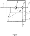
- a liquid purification method ( Fig. 1 ) purification of raw liquid is accomplished in the following manner.
- Raw liquid is fed through a raw liquid feed line (1) into a liquid purification unit (2), wherefrom the raw liquid is routed through a raw liquid/drain liquid mixing line (5), via a pressure increasing means (3), to a liquid purification means (4).
- the pressure increasing means can be, but not limited to, in the form of a membrane (diaphragm) pump ( Figs. 1 and 3 ).
- a flow restrictor is mounted in a recirculation line (6) (not shown in Figs. 1 and 3 ).
- the system ( Fig. 1 ).
- a pressure increasing means (3) in the form of a membrane (diaphragm) pump mounted in the raw liquid feed line and an additional pressure increasing device (13) in the form of a circulating pump mounted in a raw liquid/drain liquid supply line (16).
- drain liquid Downstream of the liquid purification means (4), drain liquid is supplied through the recirculation line (6) to the raw liquid/drain liquid mixing line (5) and via the pressure increasing means (3) to the liquid purification means (4).
- purified liquid is fed to the purified liquid line (9).
- the liquid purification process is interrupted for a short time sufficient for flushing the liquid purification means (4), during which the polarizing layer on the inside surface of the liquid purification means (4) is destroyed by the raw liquid/drain liquid mixture.
- the valve (8) is opened in the drain discharge line (7) and the mixture of raw liquid entering through the raw liquid line into the liquid cleaning unit via the pressure increasing means (3), and drain liquid formed after completion of the filtering process is routed to the liquid purification means (4), and further through the drain discharge line (7) via the valve (8) open is discharged from the system.
- the liquid purification means (4) comprises contaminants. Owing to the higher pressure on the purified liquid side in the absence of contaminants, a direct osmosis phenomenon occurs, at which the purified liquid can penetrate into the liquid purification means (4). However, the amount of purified liquid penetrating into the liquid purification means (4) will be negligible due to a check valve (Ok) mounted in the purified liquid line (9). But this amount of purified liquid is sufficient to further increase the velocity of liquid flowing through the liquid purification means (4).
- flushing of the liquid purification means (4) with a liquid medium is performed, in which raw liquid/drain liquid mixture is used as the liquid medium. Duration of this flushing is longer than that of the at least one short flushing of the liquid purification means described above.
- the valve (8) on the drain discharge line (7) is open and the mixture of the raw liquid flowing through the raw liquid line into the liquid purification unit via the pressure increasing means (3), and the drain liquid formed upon completion of the filtration process is routed to the liquid purification means (4), and then, through the drain discharge line (7), via the open valve (8) is discharged from the system.
- the duration of flushing of the liquid purification means (4) with a liquid medium exceeds that of at least one short flushing, the amount of raw liquid supplied to be mixed with drain liquid will be greater than the amount of raw liquid supplied for mixing during the short flushing. Consequently, in the flushing of the liquid purification means (4) with a liquid medium the concentration of contaminants in the raw liquid/drain liquid mixture will reduce.
- liquid purification method described above can be applied to various systems designed for its implementation, for example, the systems shown in Figs. 2 and 3 .
- a liquid mixing device (10) (Fig. 2 ) and a purified liquid accumulation tank (18) ( Fig. 3 ) are connected to the recirculation line (6) to increase the amount of liquid flowing through the recirculation line (6).
- a liquid purification method ( Fig. 2 ) purification of raw liquid is accomplished as follows.
- Raw liquid is fed through a raw liquid feed line (1) via an open valve (15) mounted thereon into a liquid purification unit (2).
- the raw liquid is routed via a pressure increasing means (3) mounted in the raw liquid feed line (1) to a line (5) for mixing the raw liquid with drain liquid formed in the liquid purification process, and further to a liquid mixing device (10).
- the liquid mixing device (10) is a pressure tank, the inner space of which is separated by a flexible partition into a cavity (11) filled with a compressible medium, e.g. air, and a cavity (12) for mixing raw and drain liquids.
- raw liquid is routed to the raw liquid/drain liquid mixture supply line (16), and then, via an additional pressure increasing means (13) mounted in the raw liquid/drain liquid mixture supply line (16), the raw liquid is supplied into the liquid purification means (4).
- purified liquid is fed to the purified liquid line (9).
- the purified liquid is routed to a purified liquid unit (19).
- purified liquid is supplied to an accumulation tank (18) or, via an open purified liquid supply means (17), to consumer.
- Drain liquid is fed after the liquid purification means (4) to the recirculation line (6) and, via a connection unit (14), to the raw liquid/drain liquid mixing line (5).
- raw liquid in the raw liquid feed line (1) is kept being routed via the pressure increasing means (3) and the connection unit (14) to the raw liquid/drain liquid mixing line (5).
- the resulting raw liquid/drain liquid mixture is fed into a cavity (12) of the liquid mixing device (10).
- the raw and drain liquids are additionally mixed, so the mixture entering through the raw liquid/drain liquid mixture supply line (16) into the liquid purification means (4) is more homogeneous.
- Flushing of the liquid purification means (4) with the raw liquid/drain liquid mixture in the amount not exceeding the amount of liquid in the liquid purification means (4) is carried out as follows.
- a drain discharge valve (8) on the drain discharge line (7) is opened, while the supply of raw liquid to the raw liquid feed line (1) to the liquid purification unit (2) is not interrupted.
- the raw liquid/drain liquid mixture is routed through a mixing cavity (12) with a velocity higher than that of liquid medium at flushing of the liquid cleaning means (4) with a liquid medium, through the raw liquid/drain liquid mixture line (16), via a liquid velocity increasing device (13) to the liquid purification means (4), and then is discharged into drain through the drain discharge line (7) with the drain discharge valve (8) open.
- the raw liquid/drain liquid mixing device (10) is intended to accumulate pressure. At short flushing, when the drain discharge valve (8) is closed, the liquid purification means (4) is subject to hydraulic impacts caused by pressure surge in the system. Pressure is accumulated in the raw liquid/drain liquid mixing device (10) disposed downstream of the pressure increasing means (3). Raw liquid is supplied through the raw liquid feed line (1), via the pressure increasing means (3) in pressurized state to a raw liquid/concentrate mixing cavity (12). Since the cavity (11) comprises a compressible medium, pressure in the cavity (11) will increase as the cavity (12) is filled with liquid. Upon opening the valve (8) on the drain discharge line (7) the raw liquid/drain liquid mixture acquires a high velocity due to the counter pressure of the cavity (11) and the cavity (12). Upon closing the valve (8) in the drain discharge line (7), the pressure accumulated in the mixing device (10) will decrease the hydraulic impact in the liquid cleaner (4).
- drain liquid is removed from the liquid mixing device (10).
- the process is carried out as follows.
- the valve (15) in the raw liquid feed line (1) is closed, the pressure increasing means (3) is deactivated, and the valve (8) on the drain discharge line (7) is opened. Drain liquid is routed from the cavity (12) of the raw liquid/drain liquid mixing device (10) through the raw liquid/drain liquid mixture supply line (16), via the liquid velocity increasing means (13), to the liquid purification means (4), and further, through the drain discharge line (7) with the drain discharge valve open (8), is discharged into drain.
- the liquid purification means (4) is flushed with a liquid medium, which is the raw liquid/drain liquid mixture.
- a liquid medium which is the raw liquid/drain liquid mixture.
- the liquid velocity increasing means (4) is activated, the valve (15) in the raw liquid feed line (1) and the valve (8) in the drain discharge line (7) are opened.
- Raw liquid is fed through the raw liquid feed line (1) to the liquid purification unit (2) via the pressure increasing means (3).
- raw liquid purification unit (2) raw liquid is mixed with the drain liquid remaining in the system.
- the resulting mixture is fed via the raw liquid/drain liquid mixing device (10), through the raw liquid/drain liquid mixture supply line (16), via the fluid velocity increasing device and the liquid purification means (4) to the drain discharge line (7), and is discharged into drain with the valve (8) open.
- a liquid purification method ( Fig.3 ) purification of raw liquid is accomplished as follows.
- Raw liquid is fed through a raw liquid feed line (1) into a filtration unit (2).
- the raw liquid feed line (1) is connected through a connection unit (14) to a raw liquid and concentrate mixing line (5) and a secondary line (13) connected to a displacement cavity (11) of a liquid-liquid tank (10).
- raw liquid is routed through the secondary line (13) to the displacement cavity (11) of the liquid-liquid tank (10), and simultaneously through a raw liquid/drain liquid mixing line (5), via a pressure increasing means (3), to liquid purification means (4).
- the purified liquid is supplied through a purified liquid line (9) to a purified liquid accumulation cavity (12) for the liquid-liquid tank (10).
- drain liquid is supplied through a recirculation line (6) connected to a drain discharge line (7) to a drain liquid displacement cavity (11) of the liquid-liquid tank (10). Drain liquid entering the displacement cavity (11) replaces the raw liquid contained in the cavity (11).
- drain liquid will flow from the displacement cavity (11) through the secondary line (13), via the connection unit (14), into the raw liquid/drain liquid mixing line (5) and via the pressure increasing means (3) to the liquid purification means (4).
- the purified liquid supply means (17) connected to the purified liquid line (9) is opened, the purified liquid is supplied to consumer.
- the raw liquid/drain liquid mixture is supplied to the drain discharge line (7) in the following manner.
- the liquid purification process is interrupted, and drain liquid does not flow through the recirculation line (6) into the displacement cavity (11).
- the valve (8) in the drain discharge line (7) When the valve (8) in the drain discharge line (7) is opened, the raw liquid/drain liquid mixture is supplied through the raw liquid/drain liquid mixing line (5), via the pressure increasing means (3) and the liquid purification means (4), to the drain discharge line, and, at the same time, drain liquid from the displacement cavity (11) enters through the recirculation line (6) into the drain discharge line (7).
- the two liquid flows are joined in the drain discharge line (7) and discharged from the system through the open valve (8).
- the present liquid purification method reduces the amount of raw liquid used, and at the same time reduces the amount of contaminants on the liquid purification means and extends the life of the purification means.
- the total amount of raw liquid/drain liquid used in short and long flushings of the liquid purification means according to the present liquid purification method is less than the total amount of raw liquid used in flushing of the liquid purification means in the most closely related prior art method. Furthermore, the most closely related method uses purified liquid in the additional flushing. According to the present liquid purification method, the total amount of purified liquid is supplied to consumer.
Landscapes
- Chemical & Material Sciences (AREA)
- Engineering & Computer Science (AREA)
- Water Supply & Treatment (AREA)
- Chemical Kinetics & Catalysis (AREA)
- Nanotechnology (AREA)
- Life Sciences & Earth Sciences (AREA)
- Hydrology & Water Resources (AREA)
- Environmental & Geological Engineering (AREA)
- Organic Chemistry (AREA)
- Separation Using Semi-Permeable Membranes (AREA)
- Cleaning By Liquid Or Steam (AREA)
- Cleaning In General (AREA)
Abstract
Description
- The invention relates to a method for purification and/or desalination of liquid, mostly water, which can be used in domestic and/or drinking water supply in residential and/or industrial environment, summer cottages and garden plots.
- Methods of reverse osmosis treatment of liquids involving recycling and systems for implementing the same are quite widely spread.
- A conventional liquid purification method can be implemented in a liquid purification system disclosed in patent
US 6,190,558 (B01D 61/00, Nimbus Water Systems, Inc., US, publ. Feb. 20, 2001). The liquid purification method comprises at least one automatically initiated filtration cycle involving purification of raw liquid and flushing of liquid purification means with liquid medium, wherein in the course of the cycle the raw liquid is routed to a liquid purification unit through a raw liquid feed line. In the liquid purification unit, the raw liquid is supplied into a mixing device connected to the raw liquid feed line and to a raw liquid/drain liquid mixture supply line, and further, through a pressure increasing means, to a liquid purification means; after the liquid purification means the purified liquid enters a purified liquid line wherefrom the purified liquid is supplied to consumer. Drain liquid is supplied through a recirculation line to a mixing device, such as a mixer, and further through a raw liquid/drain liquid mixture supply line via the pressure increasing means the resulting raw liquid/drain liquid mixture is routed into the liquid purification means, while a portion of the drain liquid is continuously discharged via a restrictor into drain through the drain liquid line. - The raw liquid/purified liquid mixture is used as the liquid medium in flushing of the liquid purification means. Flushing of the liquid purification means is performed in the following manner. The liquid purification system comprises a purified liquid recycling line having an inlet connected to the purified liquid line and an outlet connected to the mixing device. Purified liquid is fed through the purified liquid recycling line to the mixing device, where the purified liquid is mixed with raw liquid. After the mixing device, the resulting raw liquid/purified liquid mixture is supplied through the pressure increasing means into the liquid purification means. Then, purified liquid is supplied to the purified liquid line, and drain liquid with a lower concentration is discharged into drain. Upon reaching a predetermined reduced concentration of contaminants in the drain fluid leaving the liquid purification means, the flushing process is terminated.
- The liquid purification method involves flushing the liquid purification means with a raw liquid/purified liquid mixture. During the flushing process the liquid purification process is not interrupted, and the produced purified liquid is routed to be mixed with raw liquid through the purified liquid supply line; in so doing the concentration of contaminants in the liquid passing through the liquid purification means decreases. The resulting purified liquid is not routed to consumption, but is spent to flush the operating liquid purification means.
- Since the flushing described above is performed periodically, the contamination layer will compact and solidify with time, substantially impairing the performance of the liquid purification means, therefore, a longer time and a larger amount of the raw liquid/purified liquid mixture will be required to break and remove the contamination layer.
- In light of the foregoing, the liquid purification method comprising flushing of purification means with a raw liquid/purified liquid mixture, which is accomplished at operating liquid purification means, is not quite effective due to the high consumption of purified and raw liquid.
- Another liquid purification method can be implemented in a liquid purification system disclosed in patent
US 7,628,921 (C02F/44, Avi Efraty, Israel, publ. 08.12.2009). The liquid purification method comprises at least one automatically initiated liquid purification cycle involving purification of raw liquid and flushing of liquid purification means with a liquid medium, followed by resuming the purification of liquid; wherein in the course of the cycle, raw liquid is routed through a raw liquid feed line to a liquid purification unit, in which the raw liquid is supplied into a liquid purification means through a pressure increasing means; after the liquid purification means the purified liquid enters a purified liquid line. Drain liquid is supplied through a recirculation line, via a liquid velocity increasing means, through a raw liquid/drain liquid mixing line to the liquid purification means. Purified liquid is fed to consumption through the purified liquid line. The amount of purified liquid supplied to consumer is replaced by the equivalent amount of raw liquid. In the liquid purification system, a pressure flow-through tank is connected to the recirculation line via a valve. The pressure flow-through tank is connected, via a valve, to a secondary raw liquid feed line connected to the raw liquid feed line upstream of the pressure increasing means. During purification process, the pressure tank is disconnected from the recirculation line and from the secondary raw liquid feed line. - Upon a predetermined time of liquid purification, during which drain liquid is concentrated, the valve on the recirculation line is opened. Concentrated drain liquid is supplied to the pressure flow-through tank. At the same time, raw liquid is supplied to the liquid purification means through the raw liquid feed line, via the pressure increasing means, in the amount that replaces the entire amount of the concentrated drain liquid, while the liquid purification means is flushed with raw liquid. Once the entire concentrated drain liquid from the liquid purification means enters the pressure tank, the tank is again disconnected from the recirculation line. The liquid purification process is resumed. Raw liquid is fed to the pressure tank through the secondary raw liquid feed line. The raw liquid replacing the concentrated drain liquid in the pressure flow tank is discharged into drain through the drain discharge line, via the drain discharge valve open. Once the concentrated drain liquid is completely removed from the system, the valve on the recirculation line opens, the valve on the secondary raw liquid feed line closes, and raw liquid fills the system. Liquid purification process is resumed.
- The liquid purification method described in
US 7,628,921 , publ. 08.12.2009 (C02F/44, Avi Efraty, Israel) has a serious drawback. During one liquid purification cycle, excess volume of raw liquid is used to replace the concentrated drain liquid in the liquid purification means, and to replace the concentrated drain liquid in the pressure flow-through tank. Furthermore, in the course of liquid purification, since the concentration of contaminants in drain liquid is constantly increasing, a layer of contaminants built up on the inside surface of the membrane is also growing; this layer thickens and solidifies, thereby reducing the life of the liquid purification means. - Another liquid purification method is provided in a liquid purification system disclosed in patent
US 5,503,735 (B01 D 61/12, Water Factory Systems, US, publ. 02/04/1996). The liquid purification method comprises at least one automatically initiated liquid purification cycle involving purification of raw liquid and flushing of liquid purification means with a liquid medium, followed by resuming the liquid purification, wherein during said cycle, raw liquid is routed through a raw liquid feed line into a liquid purification unit, in which raw liquid is supplied to the liquid purification means through a pressure increasing means; after the liquid purification means, purified liquid enters a purified liquid line. Drain liquid is supplied after the liquid purification means to a drain discharge line, the most of the drain liquid being discharged into drain through a restrictor. The remaining portion of the drain liquid is routed, through a recirculation line connected to the drain discharge line, to the raw liquid feed line to be mixed with raw liquid, and the resulting mixture is supplied again through the pressure increasing means to the liquid purification means. Then, upon a predetermined period of time, the liquid purification process is interrupted for flushing the liquid purification means with a liquid medium intended to remove contaminants built up on the surface of the liquid purification means during the liquid purification process. After the liquid purification means, the liquid medium is discharged into drain via a flushing line connected a drain discharge line, via an open flushing valve mounted on the flushing line. - The liquid purification method including flushing of liquid purification means has a number of disadvantages.
- Raw liquid is used as the liquid medium in the flushing of the liquid purification means. As mentioned in the description, the time for liquid purification substantially exceeds the time for flushing of the liquid purification means. In the liquid purification process, a thin polarizing contamination layer builds up on the surface of the membrane, which attracts larger particles and causes clogging and shortening the life of the liquid purification means, and as a result, of the whole system. In the liquid purification process, most of the drain liquid is discharged into drain, only a small portion thereof being recirculated.
- A liquid purification method, most closely related to the present invention, can be implemented in a liquid purification system disclosed in International Application
WO 2002/055182 (B01D 61/00, TEKNOWSMARTZ, INNOVATIONS/TECHNOLOGY INC., US, publ. 09.01.2001). The liquid purification method involves at least one automatically initiated liquid purification cycle comprising purification of raw liquid and flushing of liquid purification means with a liquid medium, followed by resuming the purification of the liquid; wherein in the course of the cycle, raw liquid is fed into a liquid purification unit, in which the raw liquid is supplied into a liquid purification means through a pressure increasing means; after the liquid purification means, purified liquid is supplied to a purified liquid line. Drain liquid is fed through a recirculation line, via a liquid velocity increasing means, to be mixed with raw liquid in the raw liquid feed line; the resulting mixture is then fed into the liquid purification means. Upon a predetermined period of time, the liquid purification process is interrupted to flush the liquid purification means with a liquid medium intended to remove contaminants built up on the inside surface of the liquid purification means during the liquid purification process, and after the liquid purification means the liquid medium is discharged with a high velocity into drain through a drain discharge line with a drain discharge valve open. - In the liquid purification system according to International Application
WO 2002/055182 (B01D 61/00, TEKNOWSMARTZ, INNOVATIONS/TECHNOLOGY INC., US) a purified liquid unit is connected to the purified liquid line and comprises a purified liquid accumulation and disinfection tank connected to pressure increasing means. The pressure increasing means is connected to a purified liquid reservoir in the form of a water-air tank intended to supply purified liquid to consumer and to supply purified liquid to the filtration unit for additional flushing of the liquid purification means with purified liquid. - The method according to International Application
WO 2002/055182 (B01D 61/00, TEKNOWSMARTZ, INNOVATIONS/TECHNOLOGY INC., US), comprises flushing of liquid purification means, in which raw liquid is used as a liquid medium. - When the liquid purification means is flushed with raw liquid, the raw liquid is supplied through the raw liquid feed line to the fluid velocity increasing means in the form of a circulation pump mounted in the recirculation line, and further to the liquid purification means, after which liquid is supplied to the drain liquid line and is discharged from the system through a drain discharge valve open. During flushing the liquid purification means with raw liquid the pressure increasing means is deactivated. Flushing of the liquid purification means with raw liquid is accomplished until the concentration of contaminants reaches a predetermined level, and then the liquid purification process is resumed.
- The liquid purification method according to International Application
WO 2002/055182 (B01D 61/00, TEKNOWSMARTZ, INNOVATIONS/TECHNOLOGY INC., US) enables additional flushing of liquid purification means with purified liquid. The flushing can be carried out irrespective of flushing the purification means with raw liquid. - Additional flushing of liquid purification means with purified liquid is performed after filling the purified liquid tank to a predetermined level. Purified liquid contained in the purified liquid tank, such as a water-air tank, is routed through a line for supplying purified liquid to the recirculation line, and then it is discharged into drain via the liquid purification means through the drain discharge line via the drain discharge valve open. While purified liquid is taken from the water-air tank, the tank is refilled with purified liquid, which is supplied via the pressure increasing means from a purified liquid accumulation and disinfection tank. As soon as the level of purified liquid in the purified liquid accumulation and disinfection tank drops to a predetermined level, the liquid purification process is resumed. During flushing the system with purified liquid, the pressure increasing means and the liquid velocity increasing means are disconnected.
- The above liquid purification method has a number of disadvantages. For example, a quite large amount of the raw liquid is to be spent for flushing the liquid purification means. In addition, purified liquid is used in additional flushing of the liquid purification means. To accomplish the liquid purification method, it is necessary that both the liquid increasing pressure means and the liquid velocity increasing means were operating simultaneously, which increases power consumption.
- The object and technical effect attained by the invention is to provide a novel liquid purification method that can reduce the amount of raw liquid used and simultaneously reduce the amount of contaminants on liquid purification means, thereby extending the life of liquid purification means.
- The object and the required technical effect are attained in a liquid purification method comprising at least one automatically initiated liquid purification cycle involving purification of a raw liquid and flushing of a liquid purification means with a liquid medium, followed by resuming the purification of liquid; wherein in the course of the cycle the raw liquid is routed through a raw liquid feed line to a liquid purification unit, in which the raw liquid is supplied via a pressure increasing means through a raw liquid/drain liquid mixing line to the liquid purification means; downstream of the liquid purification means the purified liquid enters a purified liquid line, and the drain liquid is supplied through a recirculation line to be mixed with raw liquid, and the resulting mixture flows to the liquid purification means, and then, after a predetermined period of time, the liquid purification process is interrupted for flushing the liquid purification means with a liquid medium intended to remove contaminants built up on the inside surface of the liquid purification means in the process of liquid purification; downstream of the liquid purification means the liquid medium is discharged with a high velocity into drain through a drain discharge line with a drain discharge valve open, wherein according to the invention, during said at least one liquid purification cycle, prior to flushing the liquid purification means with a liquid medium, the liquid purification process is interrupted at least once for a short period of time sufficient for flushing the liquid purification means with the drain liquid and raw liquid mixture, at which a polarizing contamination layer built up on the inside surface of the liquid purification means is destroyed, and the liquid purification process is resumed after each short flushing of the liquid purification means, and the raw liquid/drain liquid mixture is used as the liquid medium in said flushing of the liquid purification means with a liquid medium, the duration of which exceeds that of the at least one flushing of the liquid purification means, at which the polarizing layer built up on the surface of the liquid purification means is destroyed; wherein said short flushing of the liquid purification means, at which the polarizing contamination layer built up on the inside surface of the liquid purification means is destroyed, and said flushing of the liquid purification means with the liquid medium are performed with the pressure increasing means activated; wherein in the liquid purification unit, downstream of the pressure increasing means, prior to supplying to the liquid purification means through the raw liquid/drain liquid mixing line, the raw liquid is routed into a liquid mixing device adapted to accumulate pressure, then the raw liquid is routed through the raw liquid/drain liquid mixture supply line connected to the liquid mixing device, via an additional pressure increasing means mounted thereon, into the liquid purification means; then the purified liquid is supplied to the purified liquid line, and through the purified liquid supply means to consumer, and drain liquid is supplied through the recirculation line connected to the drain liquid outlet of the liquid purification means to the raw liquid/drain liquid mixing line, and further to the liquid mixing device; wherein during said flushings of the liquid purification means the velocity of the raw liquid/drain liquid mixture flow from the mixing device in the raw liquid/drain liquid mixture supply line through an additional pressure increasing means to the liquid purification means is increased, and then the raw liquid/drain liquid mixture is discharged into drain through the drain discharge valve open; wherein during one filtration cycle, upon completion of liquid purification, prior to flushing the liquid purification means with a liquid medium, the raw liquid/drain liquid mixture is removed from the liquid mixing device at the closed valve in the raw liquid feed line and the open valve in the drain discharge line, which is routed through an additional pressure increasing means to the liquid purification means, and then discharged into drain through the drain discharge line with the drain discharge valve open; wherein in the process of liquid purification process in the liquid purification unit the raw liquid is routed, through a pressure increasing means mounted in the raw liquid/drain liquid mixing line, through the raw liquid/drain liquid mixing line into the liquid purification means; then the purified liquid is supplied through the purified liquid line into a purified liquid accumulation cavity of a liquid-liquid tank, and drain liquid is recycled through a recirculation line into a displacement cavity of the liquid-liquid tank; and as the accumulation cavity is filled with purified liquid, the displaced liquid from the displacement cavity is supplied to the raw liquid/drain liquid mixing line, and upon opening the purified liquid supply means the purified liquid is supplied from the cavity through the purified liquid line to consumer; wherein at said short flushing of the liquid purification means, at which the polarizing contamination layer built up on the inside surface of the liquid purification means is destroyed, and at said flushing of the liquid purification means with a liquid medium, the raw liquid/drain liquid mixture is supplied to the drain discharge line simultaneously through the raw liquid/drain liquid mixing line through the liquid pressure increasing means and the liquid purification means, and through the recirculation line from the displacement cavity of the liquid-liquid tank.
-
Fig. 1 shows a flowchart of the liquid purification method. -
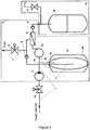
Fig. 2 shows a schematic diagram of a system for implementing the liquid purification method, comprising a mixing device in the form of a pressure tank with a cavity for mixing raw liquid with drain liquid and a cavity for compressible medium. -
Fig. 3 shows a schematic diagram of a system for implementing the liquid purification method, comprising a liquid accumulation reservoir of liquid-liquid type, which comprises a purified liquid accumulation cavity and a drain liquid displacement cavity. - According to a liquid purification method (
Fig. 1 ), purification of raw liquid is accomplished in the following manner. Raw liquid is fed through a raw liquid feed line (1) into a liquid purification unit (2), wherefrom the raw liquid is routed through a raw liquid/drain liquid mixing line (5), via a pressure increasing means (3), to a liquid purification means (4). The pressure increasing means can be, but not limited to, in the form of a membrane (diaphragm) pump (Figs. 1 and3 ). In this case, a flow restrictor is mounted in a recirculation line (6) (not shown inFigs. 1 and3 ). Alternatively, the system (Fig. 2 ) can be equipped with a pressure increasing means (3) in the form of a membrane (diaphragm) pump mounted in the raw liquid feed line and an additional pressure increasing device (13) in the form of a circulating pump mounted in a raw liquid/drain liquid supply line (16). Downstream of the liquid purification means (4), drain liquid is supplied through the recirculation line (6) to the raw liquid/drain liquid mixing line (5) and via the pressure increasing means (3) to the liquid purification means (4). After the liquid purification means (4), purified liquid is fed to the purified liquid line (9). - After a predetermined time, the liquid purification process is interrupted for a short time sufficient for flushing the liquid purification means (4), during which the polarizing layer on the inside surface of the liquid purification means (4) is destroyed by the raw liquid/drain liquid mixture. At the same time, the valve (8) is opened in the drain discharge line (7) and the mixture of raw liquid entering through the raw liquid line into the liquid cleaning unit via the pressure increasing means (3), and drain liquid formed after completion of the filtering process is routed to the liquid purification means (4), and further through the drain discharge line (7) via the valve (8) open is discharged from the system. The raw liquid/drain liquid mixture, passing over the inside surface of the liquid purification means (4), destroys the thin polarizing layer built up on the inside surface of the liquid purification means (4). Upon completion of short flushing, the valve (8) on the drain discharge line (7) is closed and the liquid purification process is resumed. Such alternation of purification process and short flushings of the liquid purification means (4) is carried out before flushing the liquid purification means (4) with a liquid medium a predetermined number of times, depending on the rate of contamination of the raw liquid. In the short flushing of the liquid purification means (4), pressure at the purified liquid outlet in the liquid purification means will be substantially lower than pressure in the purified liquid line (9). Furthermore, in contrast to the purified liquid line (9), the liquid purification means (4) comprises contaminants. Owing to the higher pressure on the purified liquid side in the absence of contaminants, a direct osmosis phenomenon occurs, at which the purified liquid can penetrate into the liquid purification means (4). However, the amount of purified liquid penetrating into the liquid purification means (4) will be negligible due to a check valve (Ok) mounted in the purified liquid line (9). But this amount of purified liquid is sufficient to further increase the velocity of liquid flowing through the liquid purification means (4).
- Then flushing of the liquid purification means (4) with a liquid medium is performed, in which raw liquid/drain liquid mixture is used as the liquid medium. Duration of this flushing is longer than that of the at least one short flushing of the liquid purification means described above. In the process of flushing of the liquid purification means (4) with a liquid medium, the valve (8) on the drain discharge line (7) is open and the mixture of the raw liquid flowing through the raw liquid line into the liquid purification unit via the pressure increasing means (3), and the drain liquid formed upon completion of the filtration process is routed to the liquid purification means (4), and then, through the drain discharge line (7), via the open valve (8) is discharged from the system. Since the duration of flushing of the liquid purification means (4) with a liquid medium exceeds that of at least one short flushing, the amount of raw liquid supplied to be mixed with drain liquid will be greater than the amount of raw liquid supplied for mixing during the short flushing. Consequently, in the flushing of the liquid purification means (4) with a liquid medium the concentration of contaminants in the raw liquid/drain liquid mixture will reduce.
- Once flushing of the liquid purification means (4) with a liquid medium is completed, the valve (8) on the drain discharge line (7) is closed, and liquid purification process is resumed.
- The liquid purification method described above can be applied to various systems designed for its implementation, for example, the systems shown in
Figs. 2 and3 . In the systems described below, a liquid mixing device (10) (Fig. 2 ) and a purified liquid accumulation tank (18) (Fig. 3 ) are connected to the recirculation line (6) to increase the amount of liquid flowing through the recirculation line (6). - According to a liquid purification method (
Fig. 2 ), purification of raw liquid is accomplished as follows. Raw liquid is fed through a raw liquid feed line (1) via an open valve (15) mounted thereon into a liquid purification unit (2). In the liquid purification unit (2), the raw liquid is routed via a pressure increasing means (3) mounted in the raw liquid feed line (1) to a line (5) for mixing the raw liquid with drain liquid formed in the liquid purification process, and further to a liquid mixing device (10). The liquid mixing device (10) is a pressure tank, the inner space of which is separated by a flexible partition into a cavity (11) filled with a compressible medium, e.g. air, and a cavity (12) for mixing raw and drain liquids. After the liquid mixing device (10), raw liquid is routed to the raw liquid/drain liquid mixture supply line (16), and then, via an additional pressure increasing means (13) mounted in the raw liquid/drain liquid mixture supply line (16), the raw liquid is supplied into the liquid purification means (4). After the liquid purification means (4), purified liquid is fed to the purified liquid line (9). Through the purified liquid line (9), the purified liquid is routed to a purified liquid unit (19). In the purified liquid unit (19), purified liquid is supplied to an accumulation tank (18) or, via an open purified liquid supply means (17), to consumer. - Drain liquid is fed after the liquid purification means (4) to the recirculation line (6) and, via a connection unit (14), to the raw liquid/drain liquid mixing line (5). At the same time, raw liquid in the raw liquid feed line (1) is kept being routed via the pressure increasing means (3) and the connection unit (14) to the raw liquid/drain liquid mixing line (5). Further, the resulting raw liquid/drain liquid mixture is fed into a cavity (12) of the liquid mixing device (10). In the cavity (12) of the liquid mixing device (10) the raw and drain liquids are additionally mixed, so the mixture entering through the raw liquid/drain liquid mixture supply line (16) into the liquid purification means (4) is more homogeneous.
- Flushing of the liquid purification means (4) with the raw liquid/drain liquid mixture in the amount not exceeding the amount of liquid in the liquid purification means (4) is carried out as follows. A drain discharge valve (8) on the drain discharge line (7) is opened, while the supply of raw liquid to the raw liquid feed line (1) to the liquid purification unit (2) is not interrupted. The raw liquid/drain liquid mixture is routed through a mixing cavity (12) with a velocity higher than that of liquid medium at flushing of the liquid cleaning means (4) with a liquid medium, through the raw liquid/drain liquid mixture line (16), via a liquid velocity increasing device (13) to the liquid purification means (4), and then is discharged into drain through the drain discharge line (7) with the drain discharge valve (8) open. The raw liquid/drain liquid mixing device (10) is intended to accumulate pressure. At short flushing, when the drain discharge valve (8) is closed, the liquid purification means (4) is subject to hydraulic impacts caused by pressure surge in the system. Pressure is accumulated in the raw liquid/drain liquid mixing device (10) disposed downstream of the pressure increasing means (3). Raw liquid is supplied through the raw liquid feed line (1), via the pressure increasing means (3) in pressurized state to a raw liquid/concentrate mixing cavity (12). Since the cavity (11) comprises a compressible medium, pressure in the cavity (11) will increase as the cavity (12) is filled with liquid. Upon opening the valve (8) on the drain discharge line (7) the raw liquid/drain liquid mixture acquires a high velocity due to the counter pressure of the cavity (11) and the cavity (12). Upon closing the valve (8) in the drain discharge line (7), the pressure accumulated in the mixing device (10) will decrease the hydraulic impact in the liquid cleaner (4).
- During one filtration cycle, upon completion of liquid purification, before flushing the liquid purification means (4) with a liquid medium, drain liquid is removed from the liquid mixing device (10). The process is carried out as follows. At the same time, the valve (15) in the raw liquid feed line (1) is closed, the pressure increasing means (3) is deactivated, and the valve (8) on the drain discharge line (7) is opened. Drain liquid is routed from the cavity (12) of the raw liquid/drain liquid mixing device (10) through the raw liquid/drain liquid mixture supply line (16), via the liquid velocity increasing means (13), to the liquid purification means (4), and further, through the drain discharge line (7) with the drain discharge valve open (8), is discharged into drain.
- After removal of drain liquid from the raw liquid/concentrate mixing device (10), the liquid purification means (4) is flushed with a liquid medium, which is the raw liquid/drain liquid mixture. During the flushing process, simultaneously, the liquid velocity increasing means (4) is activated, the valve (15) in the raw liquid feed line (1) and the valve (8) in the drain discharge line (7) are opened. Raw liquid is fed through the raw liquid feed line (1) to the liquid purification unit (2) via the pressure increasing means (3). In the liquid purification unit (2), raw liquid is mixed with the drain liquid remaining in the system. The resulting mixture is fed via the raw liquid/drain liquid mixing device (10), through the raw liquid/drain liquid mixture supply line (16), via the fluid velocity increasing device and the liquid purification means (4) to the drain discharge line (7), and is discharged into drain with the valve (8) open.
- Upon completion of flushing of the liquid purification means (4) with a liquid medium, liquid purification process is resumed.
- According to a liquid purification method (
Fig.3 ), purification of raw liquid is accomplished as follows. Raw liquid is fed through a raw liquid feed line (1) into a filtration unit (2). In the filtration unit (2), the raw liquid feed line (1) is connected through a connection unit (14) to a raw liquid and concentrate mixing line (5) and a secondary line (13) connected to a displacement cavity (11) of a liquid-liquid tank (10). In the filtration unit (2), raw liquid is routed through the secondary line (13) to the displacement cavity (11) of the liquid-liquid tank (10), and simultaneously through a raw liquid/drain liquid mixing line (5), via a pressure increasing means (3), to liquid purification means (4). After the liquid purification means (4), the purified liquid is supplied through a purified liquid line (9) to a purified liquid accumulation cavity (12) for the liquid-liquid tank (10). After the liquid purification means (4), drain liquid is supplied through a recirculation line (6) connected to a drain discharge line (7) to a drain liquid displacement cavity (11) of the liquid-liquid tank (10). Drain liquid entering the displacement cavity (11) replaces the raw liquid contained in the cavity (11). As the accumulation cavity (12) is filled with liquid, drain liquid will flow from the displacement cavity (11) through the secondary line (13), via the connection unit (14), into the raw liquid/drain liquid mixing line (5) and via the pressure increasing means (3) to the liquid purification means (4). When the purified liquid supply means (17) connected to the purified liquid line (9) is opened, the purified liquid is supplied to consumer. - In the system shown in
Fig. 3 , which enables implementing the described liquid purification method, at the flushing of the liquid purification means (4), in which the polarizing contamination layer built up on the inside surface of the liquid purification means (4) is destroyed, and at the flushing of the liquid purification means (4) with a liquid medium, the raw liquid/drain liquid mixture is supplied to the drain discharge line (7) in the following manner. During flushing of the liquid purification means (4), the liquid purification process is interrupted, and drain liquid does not flow through the recirculation line (6) into the displacement cavity (11). When the valve (8) in the drain discharge line (7) is opened, the raw liquid/drain liquid mixture is supplied through the raw liquid/drain liquid mixing line (5), via the pressure increasing means (3) and the liquid purification means (4), to the drain discharge line, and, at the same time, drain liquid from the displacement cavity (11) enters through the recirculation line (6) into the drain discharge line (7). The two liquid flows are joined in the drain discharge line (7) and discharged from the system through the open valve (8). - As stated earlier, the present liquid purification method reduces the amount of raw liquid used, and at the same time reduces the amount of contaminants on the liquid purification means and extends the life of the purification means.
- In contrast to the most closely related prior art method, only raw liquid/drain liquid mixture is used for flushing the liquid purification means. Destruction of the polarizing layer built up on the inside surface of the liquid purification means occurs during flushing the liquid purification means with the raw liquid/drain liquid mixture in the amount not exceeding the amount of liquid in the liquid purification means. This reduces the amount of liquid (raw liquid/drain liquid mixture) discharged into drain, and hence the amount of raw liquid used to flush the liquid purification means. The flushing of the liquid purification means with a liquid medium is also carried out with raw liquid/drain liquid mixture, and duration of such flushing exceeds that of the flushing which causes destruction of the polarizing layer. However, the total amount of raw liquid/drain liquid used in short and long flushings of the liquid purification means according to the present liquid purification method is less than the total amount of raw liquid used in flushing of the liquid purification means in the most closely related prior art method. Furthermore, the most closely related method uses purified liquid in the additional flushing. According to the present liquid purification method, the total amount of purified liquid is supplied to consumer.
- The description represents a preferred embodiment of the invention. Various modifications can be made in the invention without departing from the scope of claims, thereby enabling its wide use.
Claims (7)
- A liquid purification method comprising at least one automatically initiated liquid purification cycle involving purification of a raw liquid and flushing of a liquid purification means with a liquid medium, followed by resuming the purification of liquid; wherein in the course of the cycle the raw liquid is routed through a raw liquid feed line to a liquid purification unit, in which the raw liquid is supplied via a pressure increasing means through a raw liquid/drain liquid mixing line to the liquid purification means; downstream of the liquid purification means the purified liquid enters a purified liquid line, and the drain liquid is supplied through a recirculation line to be mixed with raw liquid, and the resulting mixture flows to the liquid purification means, and then, after a predetermined period of time, the liquid purification process is interrupted for flushing the liquid purification means with a liquid medium intended to remove contaminants built up on the inside surface of the liquid purification means in the process of liquid purification; downstream of the liquid purification means the liquid medium is discharged with a high velocity into drain through a drain discharge line with a drain discharge valve open, characterized in that during said at least one liquid purification cycle, prior to flushing the liquid purification means with a liquid medium, the liquid purification process is interrupted at least once for a short period of time sufficient for flushing the liquid purification means with the drain liquid/raw liquid mixture, at which a polarizing contamination layer built up on the inside surface of the liquid purification means is destroyed, and the liquid purification process is resumed after each short flushing of the liquid purification means, and the raw liquid/drain liquid mixture is used as the liquid medium in said flushing of the liquid purification means with a liquid medium, the duration of which exceeds that of the at least one flushing of the liquid purification means, at which the polarizing layer built up on the surface of the liquid purification means is destroyed.
- The liquid purification method according to claim 1, characterized in that said short flushing of the liquid purification means, at which the polarizing contamination layer built up on the inside surface of the liquid purification means is destroyed, and said flushing of the liquid purification means with the liquid medium are performed with the pressure increasing means activated.
- The liquid purification method according to claim 1, characterized in that in the liquid purification unit, downstream of the pressure increasing means, prior to supplying to the liquid purification means through the raw liquid/drain liquid mixing line, the raw liquid is routed into a liquid mixing device adapted to accumulate pressure, then the raw liquid is routed through the raw liquid/drain liquid mixture supply line connected to the liquid mixing device, via an additional pressure increasing means mounted thereon, into the liquid purification means; then the purified liquid is supplied to the purified liquid line, and through the purified liquid supply means to the consumer, and the drain liquid is supplied through the recirculation line connected to the drain liquid outlet of the liquid purification means to the raw liquid/drain liquid mixing line, and further to the liquid mixing device.
- The liquid purification method according to claim 3, characterized in that during said flushings of the liquid purification means the velocity of the raw liquid/drain liquid mixture flow from the mixing device in the raw liquid/drain liquid mixture supply line through an additional pressure increasing means to the liquid purification mean is increased, and then the raw liquid/drain liquid mixture is discharged into drain through the drain discharge valve open.
- The liquid purification method according to claim 1 or 4, characterized in that during one filtration cycle, upon completion of liquid purification, prior to flushing the liquid purification means with a liquid medium, the raw liquid/drain liquid mixture is removed from the liquid mixing device at the closed valve in the raw liquid feed line and the open valve in the drain discharge line, which is routed through an additional pressure increasing means to the liquid purification means, and then discharged into drain through the drain discharge line with the drain discharge valve open.
- The liquid purification method according to claim 1, characterized in that in the liquid purification process in the liquid purification unit the raw liquid is routed, through a pressure increasing means mounted on the raw liquid/drain liquid mixing line, through the raw liquid/drain liquid mixing line into the liquid purification means; then the purified liquid is supplied through the purified liquid line into a purified liquid accumulation cavity of a liquid-liquid tank, and the drain liquid is recycled through a recirculation line into a displacement cavity of the liquid-liquid tank; and as the accumulation cavity is filled with purified liquid, the displaced liquid from the displacement cavity is supplied to the raw liquid/drain liquid mixing line, and upon opening the purified liquid supply means the purified liquid is supplied from the cavity through the purified liquid line to consumer.
- The liquid purification method according to claim 1 or 6, characterized in that at said short flushing of the liquid purification means, at which the polarizing contamination layer built up on the inside surface of the liquid purification means is destroyed, and at said flushing of the liquid purification means with a liquid medium, the raw liquid/drain liquid mixture is supplied to the drain discharge line simultaneously through the raw liquid/drain liquid mixing line through the liquid pressure increasing means and the liquid purification means, and through the recirculation line from the displacement cavity of the liquid-liquid tank.
Priority Applications (1)
| Application Number | Priority Date | Filing Date | Title |
|---|---|---|---|
| DE16842406.7T DE16842406T1 (en) | 2015-09-02 | 2016-07-21 | PROCESS FOR CLEANING A LIQUID |
Applications Claiming Priority (2)
| Application Number | Priority Date | Filing Date | Title |
|---|---|---|---|
| RU2015137551A RU2628389C2 (en) | 2015-09-02 | 2015-09-02 | Liquid purification method |
| PCT/RU2016/000464 WO2017039484A1 (en) | 2015-09-02 | 2016-07-21 | Method for purifying a liquid |
Publications (2)
| Publication Number | Publication Date |
|---|---|
| EP3345871A1 true EP3345871A1 (en) | 2018-07-11 |
| EP3345871A4 EP3345871A4 (en) | 2019-10-09 |
Family
ID=58188111
Family Applications (1)
| Application Number | Title | Priority Date | Filing Date |
|---|---|---|---|
| EP16842406.7A Pending EP3345871A4 (en) | 2015-09-02 | 2016-07-21 | Method for purifying a liquid |
Country Status (7)
| Country | Link |
|---|---|
| US (1) | US11103830B2 (en) |
| EP (1) | EP3345871A4 (en) |
| CN (1) | CN108473341B (en) |
| DE (1) | DE16842406T1 (en) |
| MA (1) | MA43944A (en) |
| RU (1) | RU2628389C2 (en) |
| WO (1) | WO2017039484A1 (en) |
Cited By (2)
| Publication number | Priority date | Publication date | Assignee | Title |
|---|---|---|---|---|
| US11103830B2 (en) | 2015-09-02 | 2021-08-31 | Electrophor, Inc. | Method for purifying a liquid |
| US11439955B2 (en) | 2015-09-02 | 2022-09-13 | Electrophor, Inc. | System for purifying a liquid |
Families Citing this family (5)
| Publication number | Priority date | Publication date | Assignee | Title |
|---|---|---|---|---|
| RU2754624C2 (en) * | 2019-02-12 | 2021-09-06 | Общество С Ограниченной Ответственностью "Аквафор" (Ооо "Аквафор") | Liquid purifying system |
| RU2741439C1 (en) * | 2019-09-24 | 2021-01-26 | Общество С Ограниченной Ответственностью "Аквафор" (Ооо "Аквафор") | Device for membrane cleaning of liquid |
| RU2721523C1 (en) * | 2019-11-12 | 2020-05-19 | Общество С Ограниченной Ответственностью "Аквафор" (Ооо "Аквафор") | Liquid cleaning system |
| RU2746484C1 (en) * | 2020-08-19 | 2021-04-14 | Общество С Ограниченной Ответственностью "Аквафор" (Ооо "Аквафор") | Liquid purification system |
| EP4212234A1 (en) * | 2022-01-13 | 2023-07-19 | GEA Process Engineering A/S | A method for use in cleaning a processing system and a processing system |
Family Cites Families (81)
| Publication number | Priority date | Publication date | Assignee | Title |
|---|---|---|---|---|
| US2910836A (en) | 1957-08-12 | 1959-11-03 | Minnesota Mining & Mfg | Fluid heating and cooling apparatus |
| US3493496A (en) | 1968-05-13 | 1970-02-03 | Desalination Systems | Purified water supply apparatus and method |
| US3794172A (en) | 1972-08-29 | 1974-02-26 | Desalination Systems | Storage and dispensing apparatus for a reverse osmosis water purification system |
| US4086166A (en) | 1975-07-21 | 1978-04-25 | Ernest Newell Martin | Water filtering and dispensing apparatus |
| US4176063A (en) | 1977-10-21 | 1979-11-27 | Richard W. Beall, Jr. | Water purifier system and valve |
| US4243523A (en) | 1978-08-07 | 1981-01-06 | Allied Water Corporation | Water purification process and system |
| DE3480588D1 (en) | 1983-12-20 | 1990-01-04 | Hembrex Inc | FILTRATION METHOD AND DEVICE. |
| US4626346A (en) | 1986-02-10 | 1986-12-02 | Hall Belton E | Reverse osmosis water purification system for use in limited water supply installations |
| US4833888A (en) | 1987-01-29 | 1989-05-30 | James M. Kerner | Thermoelectric heating and/or cooling system using liquid for heat exchange |
| HU200563B (en) | 1987-03-06 | 1990-07-28 | Laszlo Szuecs | Method and apparatus for treating liquids consist of foreign matter by diaphragm filter device |
| US4891594A (en) | 1988-08-19 | 1990-01-02 | Resonex, Inc. | Method of optimizing flip angles in MRI for unequal delay times |
| DE8813571U1 (en) | 1988-10-28 | 1989-05-11 | Wasserboy GmbH & Co Wasserfilter-Vertrieb KG, 4972 Löhne | Water filter device |
| US5503735A (en) * | 1989-06-26 | 1996-04-02 | Water Factory Systems | Membrane filtration system with control valves for optimizing flow rates |
| US4973404A (en) | 1989-09-05 | 1990-11-27 | Aurian Corporation | Micro/ultra filtration system |
| US4997553A (en) | 1990-03-15 | 1991-03-05 | Clack Corporation | Storage and dispensing apparatus for reverse osmosis filtration purification system |
| US4981594A (en) | 1990-04-26 | 1991-01-01 | Wastewater Resources Inc. | Waste water purification system |
| SU1764094A1 (en) | 1990-07-12 | 1992-09-23 | Polyanskij Aleksandr V | Device for fluids heating or cooling |
| US5132015A (en) * | 1990-10-04 | 1992-07-21 | Rohm And Haas Company | Flow control for ultra filtration systems |
| RU2004233C1 (en) | 1991-07-23 | 1993-12-15 | Наил Анваровна Лутфуллина | Solution-purifying apparatus mainly for cucumber lotion |
| US5266203A (en) | 1992-01-30 | 1993-11-30 | Arrowhead Industrial Water, Inc. | Method for treating process streams containing cyanide and heavy metals |
| RU2047330C1 (en) * | 1992-09-24 | 1995-11-10 | Научно-производственное предприятие "Мембранная технология" | Method for producing potable water |
| RU2100295C1 (en) | 1994-02-11 | 1997-12-27 | Виталий Александрович Васильев | Water treatment installation |
| US5520816A (en) | 1994-08-18 | 1996-05-28 | Kuepper; Theodore A. | Zero waste effluent desalination system |
| CA2197525A1 (en) | 1996-02-14 | 1997-08-15 | Mahabala R. Adiga | Plating waste water treatment and metals recovery method |
| US6093312A (en) | 1998-01-22 | 2000-07-25 | Entre Pure, Inc. | Ice dispenser with an air-cooled bin |
| US6068764A (en) | 1998-03-03 | 2000-05-30 | Chau; Yiu Chau | Reverse osmosis pump and shut off valve |
| WO1999047226A1 (en) | 1998-03-16 | 1999-09-23 | Ionics, Incorporated | Bacteria limiting water treatment and storage systems and methods |
| NL1010544C2 (en) * | 1998-11-13 | 2000-05-16 | Stork Friesland Bv | Method and device for removing suspended matter and salts from a liquid by means of membrane filtration. |
| US6290856B1 (en) | 1999-02-18 | 2001-09-18 | World Wide Water, Inc. | Reverse osmosis system with biological contamination prevention |
| US6190558B1 (en) * | 1999-04-01 | 2001-02-20 | Nimbus Water Systems, Inc. | Reverse osmosis purification system |
| NO309398B1 (en) | 1999-06-16 | 2001-01-22 | Bjoern Lyng | Process and plant for the production of fresh water from saline water |
| EP1414552A1 (en) | 2001-01-09 | 2004-05-06 | Teknowsmartz Innovations/Technology Inc. | Reverse osmosis system with controlled recirculation |
| US20020100716A1 (en) | 2001-02-01 | 2002-08-01 | Bosko Robert S. | Constant pressure filtered water delivery system |
| RU20256U1 (en) | 2001-07-30 | 2001-10-27 | Скиданов Евгений Викторович | SOLUTION SEPARATION INSTALLATION |
| RU2199377C1 (en) | 2001-12-25 | 2003-02-27 | Научно-производственное предприятие "Лисскон" | Membrane plant for separation of solutions |
| RU22434U1 (en) | 2001-12-25 | 2002-04-10 | Общество с ограниченной ответственностью Научно-производственное предприятие "Лисскон" | SOLUTION SEPARATION INSTALLATION |
| US7316774B2 (en) | 2002-07-22 | 2008-01-08 | Kinetico Incorporated | Fluid treatment system |
| IL157430A (en) * | 2003-08-17 | 2009-08-03 | Avi Efraty | Apparatus for continuous closed circuit desalination under variable pressure with a single container |
| CA2545754A1 (en) | 2003-11-12 | 2005-05-26 | Watts Regulator Co. | Zero waste reverse osmosis water filtering |
| US7338595B2 (en) | 2003-11-13 | 2008-03-04 | Culligan International Company | Flow-through tank for water treatment |
| RU2297389C2 (en) | 2005-03-25 | 2007-04-20 | Общество с ограниченной ответственностью Проектно-производственный и информационный центр "ОМНИМЕД" | Method of the drinking water purification and the installation for its implementation |
| RU2287490C1 (en) | 2005-05-03 | 2006-11-20 | Государственное образовательное учреждение высшего профессионального образования "Уфимский государственный нефтяной технический университет" | System of desalination of water |
| KR100716766B1 (en) * | 2005-08-02 | 2007-05-14 | 이희권 | Waste Water Disposal Plant By Media Biofilter |
| US7601256B2 (en) | 2005-08-26 | 2009-10-13 | Next-Ro, Inc. | Reverse osmosis filtration systems |
| US7384549B2 (en) | 2005-12-29 | 2008-06-10 | Spf Innovations, Llc | Method and apparatus for the filtration of biological solutions |
| GR1005796B (en) | 2006-02-24 | 2008-01-30 | System for the recovery of energy and the reduction of deposits on membranes in a desalination unit (of variable power and supply) by reverse osmosis | |
| DE102006015675A1 (en) | 2006-04-04 | 2007-10-11 | Wapura Trinkwasserreinigungs Gmbh | Small volume reverse osmosis system with double membrane permeate pump |
| RU2331586C2 (en) | 2006-04-25 | 2008-08-20 | Александр Егорович Бобров | Plant for purifying underground and sewage water |
| US7550084B2 (en) * | 2006-05-02 | 2009-06-23 | Watts Water Technologies, Inc. | Reverse osmosis water filtering system |
| RU2323036C2 (en) | 2006-06-15 | 2008-04-27 | Алексей Глебович Одинец | Method and device for concentrating water solutions of biology-active agents |
| RU2323766C1 (en) | 2006-09-27 | 2008-05-10 | Общество с ограниченной ответственностью ООО "Аквафор" (ООО "Аквафор") | Method of fluid filtration |
| US20090113898A1 (en) | 2007-11-02 | 2009-05-07 | Rocky Research | thermoelectric water chiller and heater apparatus |
| RU74909U1 (en) | 2007-11-20 | 2008-07-20 | ЗАО Научно-исследовательский центр "Икар" | LIQUID ACTIVATION DEVICE |
| US20100018220A1 (en) | 2008-07-25 | 2010-01-28 | Modad Allan A | Apparatus for heating or cooling and monitoring consumption of a beverage |
| JP4623204B2 (en) | 2008-11-14 | 2011-02-02 | パナソニック電工株式会社 | Water purification cartridge and water purifier |
| FR2940764A1 (en) * | 2009-01-07 | 2010-07-09 | Benoit Girousse | Cleaning device for filtration of liquid i.e. retentate, has valve cutting loop placed on retentate inlet pipe to allow closing of inlet pipe, and discharge valve located between loop and retentate inlet of another module |
| GB0906841D0 (en) | 2009-04-21 | 2009-06-03 | Aljohani Mohammed S | Nanofiltration process |
| RU89097U1 (en) | 2009-06-18 | 2009-11-27 | Закрытое акционерное общество "Научно-производственная компания "МЕДИАНА-ФИЛЬТР" | PLANT FOR PRODUCING SALTED WATER |
| RU2421270C1 (en) | 2009-10-05 | 2011-06-20 | Общество с ограниченной ответственностью "Аквафор" | Filtered water unit for water treatment system, water treatment system storage unit (versions), and water treatment system (versions) |
| US20110198275A1 (en) | 2010-02-17 | 2011-08-18 | Edwin M. Hayes | Manual foot actuated/solar power - air compressor air pressure driven, emergency reverse osmosis water purification system |
| FR2957353B1 (en) | 2010-03-10 | 2014-09-05 | Commissariat Energie Atomique | PROCESS FOR REMOVING ONE OR MORE COMPOUNDS FROM A HYDROCARBONATED LOAD |
| US8206581B2 (en) | 2010-04-05 | 2012-06-26 | Thomas E. Richetti | High efficiency reverse osmosis system |
| TWM401000U (en) | 2010-06-10 | 2011-04-01 | Puricom Water Ind Corporation | Pressure barrel for water filtration system |
| RU2473472C2 (en) * | 2010-08-09 | 2013-01-27 | Общество с ограниченной ответственностью "Системы и технологии" | Reverse osmosis water treatment plant |
| DE102010048616A1 (en) | 2010-08-27 | 2012-03-01 | Manfred Völker | Reverse osmosis water softener |
| CN202099132U (en) * | 2011-01-13 | 2012-01-04 | 江苏正本净化节水科技实业有限公司 | Reverse osmosis water purifier |
| NL2006241C2 (en) | 2011-02-17 | 2012-08-20 | Multi Purpose Ind | METHOD FOR PURIFYING WATER AND WATER PURIFICATION PLANT |
| CN102295357B (en) * | 2011-05-27 | 2013-05-22 | 张伟斌 | Drinking-water processing equipment |
| US8910799B2 (en) * | 2011-08-01 | 2014-12-16 | Enveera, Inc. | Integrated membrane system for distributed water treatment |
| RU2484884C1 (en) | 2011-12-09 | 2013-06-20 | Закрытое Акционерное Общество "Аквафор Продакшн" (Зао "Аквафор Продакшн") | Water treatment plant |
| PL2674399T3 (en) | 2012-06-13 | 2014-11-28 | Vivonic Gmbh | Device for producing ultra-pure water according to the principle of reverse osmosis |
| US20140061129A1 (en) * | 2012-09-04 | 2014-03-06 | Israel Aerospace Industries Ltd. | System and method of desalination of water |
| RU2531392C2 (en) | 2013-01-10 | 2014-10-20 | Закрытое акционерное общество "Системы водоочистки" | Precoat filter |
| JP5804228B1 (en) | 2013-12-02 | 2015-11-04 | 東レ株式会社 | Water treatment method |
| FR3017543B1 (en) * | 2014-02-14 | 2020-06-12 | Degremont | PROCESS FOR OPERATING A WATER TREATMENT PLANT, AND PLANT FOR IMPLEMENTING THE METHOD |
| RU2606986C2 (en) | 2014-10-27 | 2017-01-10 | Закрытое Акционерное Общество "Аквафор Продакшн" (Зао "Аквафор Продакшн") | Fluid cleaning system |
| RU2585191C1 (en) | 2014-12-30 | 2016-05-27 | Закрытое Акционерное Общество "Аквафор Продакшн" (Зао "Аквафор Продакшн") | Fluid cleaning system |
| CN204550144U (en) * | 2015-04-03 | 2015-08-12 | 佛山市顺德区美的饮水机制造有限公司 | Totally-enclosed backflow accumulation of energy is along washing and filtering equipment |
| RU2614705C2 (en) | 2015-04-20 | 2017-03-28 | Закрытое Акционерное Общество "Аквафор Продакшн" (Зао "Аквафор Продакшн") | Antiscalant dosing device |
| RU2614287C2 (en) | 2015-09-02 | 2017-03-24 | Закрытое Акционерное Общество "Аквафор Продакшн" (Зао "Аквафор Продакшн") | Fluid cleaning system |
| RU2628389C2 (en) | 2015-09-02 | 2017-08-16 | Закрытое Акционерное Общество "Аквафор Продакшн" (Зао "Аквафор Продакшн") | Liquid purification method |
-
2015
- 2015-09-02 RU RU2015137551A patent/RU2628389C2/en active IP Right Revival
-
2016
- 2016-07-21 DE DE16842406.7T patent/DE16842406T1/en active Pending
- 2016-07-21 MA MA043944A patent/MA43944A/en unknown
- 2016-07-21 US US15/757,024 patent/US11103830B2/en active Active
- 2016-07-21 CN CN201680063311.XA patent/CN108473341B/en active Active
- 2016-07-21 WO PCT/RU2016/000464 patent/WO2017039484A1/en active Application Filing
- 2016-07-21 EP EP16842406.7A patent/EP3345871A4/en active Pending
Cited By (2)
| Publication number | Priority date | Publication date | Assignee | Title |
|---|---|---|---|---|
| US11103830B2 (en) | 2015-09-02 | 2021-08-31 | Electrophor, Inc. | Method for purifying a liquid |
| US11439955B2 (en) | 2015-09-02 | 2022-09-13 | Electrophor, Inc. | System for purifying a liquid |
Also Published As
| Publication number | Publication date |
|---|---|
| US11103830B2 (en) | 2021-08-31 |
| EP3345871A4 (en) | 2019-10-09 |
| CN108473341B (en) | 2022-08-30 |
| MA43944A (en) | 2018-12-12 |
| WO2017039484A1 (en) | 2017-03-09 |
| DE16842406T1 (en) | 2018-11-22 |
| CN108473341A (en) | 2018-08-31 |
| RU2015137551A (en) | 2017-03-09 |
| RU2628389C2 (en) | 2017-08-16 |
| US20180345220A1 (en) | 2018-12-06 |
Similar Documents
| Publication | Publication Date | Title |
|---|---|---|
| US11103830B2 (en) | Method for purifying a liquid | |
| EP3345872B1 (en) | System for purifying a liquid | |
| CN102145257A (en) | Method for cleaning filtering membrane modules | |
| RU2410336C2 (en) | Apparatus for purifying liquid, method of washing hollow-fibre filter and application of method of washing hollow-fibre filter | |
| JP2013085993A (en) | Apparatus for purifying liquid | |
| EP2371445B1 (en) | Reverse osmosis plant for the treatment of water | |
| JP2006263501A (en) | System and method for cleaning membrane | |
| RU2585191C1 (en) | Fluid cleaning system | |
| KR200393666Y1 (en) | Apparatus for automatic cleaning of separation membrane in dipping type membrane separation system | |
| JP2007160259A (en) | Water purifying apparatus | |
| CN205933443U (en) | Full -automatic anti - water purification machine that washs | |
| JP2007111576A (en) | Back-washing method of membrane module | |
| US20200289988A1 (en) | Filtering membrane cleaning method | |
| CN115297940A (en) | Method for minimizing scaling in water filtration systems | |
| KR100463251B1 (en) | Purified system having electro dialysis | |
| JP6029904B2 (en) | Membrane filtration system and operation control method thereof | |
| CN205933442U (en) | Full -automatic infiltration water purification machine | |
| WO2015052906A1 (en) | Filtration device | |
| CN204237636U (en) | For making the water cleaning systems of mist machine | |
| CN204039105U (en) | Reverse osmosis membrane water generator | |
| EP4059899A1 (en) | An arrangement and a method of pre-filtrating a natural water transferring water pump | |
| CN208667312U (en) | A kind of waste emulsified mixture abatement system and integrated equipment | |
| TWI522159B (en) | Thin film filter module for film blocking and its application | |
| KR200365421Y1 (en) | A treatment plant of wastewater | |
| CN207153481U (en) | Anti-penetration water purifier |
Legal Events
| Date | Code | Title | Description |
|---|---|---|---|
| STAA | Information on the status of an ep patent application or granted ep patent |
Free format text: STATUS: THE INTERNATIONAL PUBLICATION HAS BEEN MADE |
|
| PUAI | Public reference made under article 153(3) epc to a published international application that has entered the european phase |
Free format text: ORIGINAL CODE: 0009012 |
|
| STAA | Information on the status of an ep patent application or granted ep patent |
Free format text: STATUS: REQUEST FOR EXAMINATION WAS MADE |
|
| 17P | Request for examination filed |
Effective date: 20180329 |
|
| AK | Designated contracting states |
Kind code of ref document: A1 Designated state(s): AL AT BE BG CH CY CZ DE DK EE ES FI FR GB GR HR HU IE IS IT LI LT LU LV MC MK MT NL NO PL PT RO RS SE SI SK SM TR |
|
| AX | Request for extension of the european patent |
Extension state: BA ME |
|
| REG | Reference to a national code |
Ref country code: DE Ref legal event code: R210 |
|
| REG | Reference to a national code |
Ref country code: FR Ref legal event code: EL |
|
| DAX | Request for extension of the european patent (deleted) | ||
| REG | Reference to a national code |
Ref country code: EE Ref legal event code: BB2E |
|
| RIC1 | Information provided on ipc code assigned before grant |
Ipc: B01D 61/12 20060101ALI20190410BHEP Ipc: B01D 65/02 20060101ALI20190410BHEP Ipc: C02F 1/44 20060101AFI20190410BHEP Ipc: B01D 61/08 20060101ALI20190410BHEP Ipc: B01D 61/02 20060101ALI20190410BHEP Ipc: B01D 65/08 20060101ALI20190410BHEP Ipc: B01D 61/00 20060101ALI20190410BHEP |
|
| A4 | Supplementary search report drawn up and despatched |
Effective date: 20190909 |
|
| RIC1 | Information provided on ipc code assigned before grant |
Ipc: B01D 61/12 20060101ALI20190903BHEP Ipc: C02F 1/44 20060101AFI20190903BHEP Ipc: B01D 65/02 20060101ALI20190903BHEP Ipc: B01D 61/08 20060101ALI20190903BHEP Ipc: B01D 61/00 20060101ALI20190903BHEP Ipc: B01D 65/08 20060101ALI20190903BHEP Ipc: B01D 61/02 20060101ALI20190903BHEP |
|
| STAA | Information on the status of an ep patent application or granted ep patent |
Free format text: STATUS: EXAMINATION IS IN PROGRESS |
|
| 17Q | First examination report despatched |
Effective date: 20210120 |
|
| STAA | Information on the status of an ep patent application or granted ep patent |
Free format text: STATUS: EXAMINATION IS IN PROGRESS |