EP3345794A1 - Airbaganordnung und verfahren zur herstellung davon - Google Patents
Airbaganordnung und verfahren zur herstellung davon Download PDFInfo
- Publication number
- EP3345794A1 EP3345794A1 EP17209724.8A EP17209724A EP3345794A1 EP 3345794 A1 EP3345794 A1 EP 3345794A1 EP 17209724 A EP17209724 A EP 17209724A EP 3345794 A1 EP3345794 A1 EP 3345794A1
- Authority
- EP
- European Patent Office
- Prior art keywords
- material web
- wall
- airbag
- chute
- flap
- Prior art date
- Legal status (The legal status is an assumption and is not a legal conclusion. Google has not performed a legal analysis and makes no representation as to the accuracy of the status listed.)
- Granted
Links
- 238000004519 manufacturing process Methods 0.000 title claims description 10
- 238000000034 method Methods 0.000 title claims description 10
- 239000000463 material Substances 0.000 claims abstract description 137
- 230000003014 reinforcing effect Effects 0.000 claims description 9
- 239000004744 fabric Substances 0.000 claims description 7
- 238000002347 injection Methods 0.000 claims description 5
- 239000007924 injection Substances 0.000 claims description 5
- 239000002184 metal Substances 0.000 claims description 3
- 239000012209 synthetic fiber Substances 0.000 claims description 3
- 229920002994 synthetic fiber Polymers 0.000 claims description 3
- 230000000149 penetrating effect Effects 0.000 claims description 2
- 230000003313 weakening effect Effects 0.000 description 6
- 230000012447 hatching Effects 0.000 description 4
- 238000001746 injection moulding Methods 0.000 description 4
- 238000004873 anchoring Methods 0.000 description 2
- 230000000694 effects Effects 0.000 description 1
- 238000012986 modification Methods 0.000 description 1
- 230000004048 modification Effects 0.000 description 1
- 238000000465 moulding Methods 0.000 description 1
- 230000000087 stabilizing effect Effects 0.000 description 1
- 239000004753 textile Substances 0.000 description 1
- 230000001960 triggered effect Effects 0.000 description 1
- 238000003466 welding Methods 0.000 description 1
Images


Classifications
-
- B—PERFORMING OPERATIONS; TRANSPORTING
- B60—VEHICLES IN GENERAL
- B60R—VEHICLES, VEHICLE FITTINGS, OR VEHICLE PARTS, NOT OTHERWISE PROVIDED FOR
- B60R21/00—Arrangements or fittings on vehicles for protecting or preventing injuries to occupants or pedestrians in case of accidents or other traffic risks
- B60R21/02—Occupant safety arrangements or fittings, e.g. crash pads
- B60R21/16—Inflatable occupant restraints or confinements designed to inflate upon impact or impending impact, e.g. air bags
- B60R21/20—Arrangements for storing inflatable members in their non-use or deflated condition; Arrangement or mounting of air bag modules or components
- B60R21/215—Arrangements for storing inflatable members in their non-use or deflated condition; Arrangement or mounting of air bag modules or components characterised by the covers for the inflatable member
-
- B—PERFORMING OPERATIONS; TRANSPORTING
- B29—WORKING OF PLASTICS; WORKING OF SUBSTANCES IN A PLASTIC STATE IN GENERAL
- B29C—SHAPING OR JOINING OF PLASTICS; SHAPING OF MATERIAL IN A PLASTIC STATE, NOT OTHERWISE PROVIDED FOR; AFTER-TREATMENT OF THE SHAPED PRODUCTS, e.g. REPAIRING
- B29C45/00—Injection moulding, i.e. forcing the required volume of moulding material through a nozzle into a closed mould; Apparatus therefor
- B29C45/14—Injection moulding, i.e. forcing the required volume of moulding material through a nozzle into a closed mould; Apparatus therefor incorporating preformed parts or layers, e.g. injection moulding around inserts or for coating articles
- B29C45/14778—Injection moulding, i.e. forcing the required volume of moulding material through a nozzle into a closed mould; Apparatus therefor incorporating preformed parts or layers, e.g. injection moulding around inserts or for coating articles the article consisting of a material with particular properties, e.g. porous, brittle
- B29C45/14786—Fibrous material or fibre containing material, e.g. fibre mats or fibre reinforced material
-
- B—PERFORMING OPERATIONS; TRANSPORTING
- B60—VEHICLES IN GENERAL
- B60R—VEHICLES, VEHICLE FITTINGS, OR VEHICLE PARTS, NOT OTHERWISE PROVIDED FOR
- B60R21/00—Arrangements or fittings on vehicles for protecting or preventing injuries to occupants or pedestrians in case of accidents or other traffic risks
- B60R21/02—Occupant safety arrangements or fittings, e.g. crash pads
- B60R21/16—Inflatable occupant restraints or confinements designed to inflate upon impact or impending impact, e.g. air bags
- B60R21/23—Inflatable members
- B60R21/235—Inflatable members characterised by their material
-
- B—PERFORMING OPERATIONS; TRANSPORTING
- B29—WORKING OF PLASTICS; WORKING OF SUBSTANCES IN A PLASTIC STATE IN GENERAL
- B29C—SHAPING OR JOINING OF PLASTICS; SHAPING OF MATERIAL IN A PLASTIC STATE, NOT OTHERWISE PROVIDED FOR; AFTER-TREATMENT OF THE SHAPED PRODUCTS, e.g. REPAIRING
- B29C45/00—Injection moulding, i.e. forcing the required volume of moulding material through a nozzle into a closed mould; Apparatus therefor
- B29C45/14—Injection moulding, i.e. forcing the required volume of moulding material through a nozzle into a closed mould; Apparatus therefor incorporating preformed parts or layers, e.g. injection moulding around inserts or for coating articles
- B29C2045/1486—Details, accessories and auxiliary operations
- B29C2045/14901—Coating a sheet-like insert smaller than the dimensions of the adjacent mould wall
-
- B—PERFORMING OPERATIONS; TRANSPORTING
- B29—WORKING OF PLASTICS; WORKING OF SUBSTANCES IN A PLASTIC STATE IN GENERAL
- B29C—SHAPING OR JOINING OF PLASTICS; SHAPING OF MATERIAL IN A PLASTIC STATE, NOT OTHERWISE PROVIDED FOR; AFTER-TREATMENT OF THE SHAPED PRODUCTS, e.g. REPAIRING
- B29C45/00—Injection moulding, i.e. forcing the required volume of moulding material through a nozzle into a closed mould; Apparatus therefor
- B29C45/0081—Injection moulding, i.e. forcing the required volume of moulding material through a nozzle into a closed mould; Apparatus therefor of objects with parts connected by a thin section, e.g. hinge, tear line
-
- B—PERFORMING OPERATIONS; TRANSPORTING
- B29—WORKING OF PLASTICS; WORKING OF SUBSTANCES IN A PLASTIC STATE IN GENERAL
- B29L—INDEXING SCHEME ASSOCIATED WITH SUBCLASS B29C, RELATING TO PARTICULAR ARTICLES
- B29L2031/00—Other particular articles
- B29L2031/30—Vehicles, e.g. ships or aircraft, or body parts thereof
- B29L2031/3005—Body finishings
- B29L2031/3038—Air bag covers
-
- B—PERFORMING OPERATIONS; TRANSPORTING
- B60—VEHICLES IN GENERAL
- B60R—VEHICLES, VEHICLE FITTINGS, OR VEHICLE PARTS, NOT OTHERWISE PROVIDED FOR
- B60R21/00—Arrangements or fittings on vehicles for protecting or preventing injuries to occupants or pedestrians in case of accidents or other traffic risks
- B60R21/02—Occupant safety arrangements or fittings, e.g. crash pads
- B60R21/16—Inflatable occupant restraints or confinements designed to inflate upon impact or impending impact, e.g. air bags
- B60R2021/161—Inflatable occupant restraints or confinements designed to inflate upon impact or impending impact, e.g. air bags characterised by additional means for controlling deployment trajectory
-
- B—PERFORMING OPERATIONS; TRANSPORTING
- B60—VEHICLES IN GENERAL
- B60R—VEHICLES, VEHICLE FITTINGS, OR VEHICLE PARTS, NOT OTHERWISE PROVIDED FOR
- B60R21/00—Arrangements or fittings on vehicles for protecting or preventing injuries to occupants or pedestrians in case of accidents or other traffic risks
- B60R21/02—Occupant safety arrangements or fittings, e.g. crash pads
- B60R21/16—Inflatable occupant restraints or confinements designed to inflate upon impact or impending impact, e.g. air bags
- B60R21/20—Arrangements for storing inflatable members in their non-use or deflated condition; Arrangement or mounting of air bag modules or components
- B60R21/215—Arrangements for storing inflatable members in their non-use or deflated condition; Arrangement or mounting of air bag modules or components characterised by the covers for the inflatable member
- B60R2021/21537—Arrangements for storing inflatable members in their non-use or deflated condition; Arrangement or mounting of air bag modules or components characterised by the covers for the inflatable member characterised by hinges
-
- B—PERFORMING OPERATIONS; TRANSPORTING
- B60—VEHICLES IN GENERAL
- B60R—VEHICLES, VEHICLE FITTINGS, OR VEHICLE PARTS, NOT OTHERWISE PROVIDED FOR
- B60R21/00—Arrangements or fittings on vehicles for protecting or preventing injuries to occupants or pedestrians in case of accidents or other traffic risks
- B60R21/02—Occupant safety arrangements or fittings, e.g. crash pads
- B60R21/16—Inflatable occupant restraints or confinements designed to inflate upon impact or impending impact, e.g. air bags
- B60R21/23—Inflatable members
- B60R21/235—Inflatable members characterised by their material
- B60R2021/23504—Inflatable members characterised by their material characterised by material
- B60R2021/23509—Fabric
-
- B—PERFORMING OPERATIONS; TRANSPORTING
- B60—VEHICLES IN GENERAL
- B60R—VEHICLES, VEHICLE FITTINGS, OR VEHICLE PARTS, NOT OTHERWISE PROVIDED FOR
- B60R21/00—Arrangements or fittings on vehicles for protecting or preventing injuries to occupants or pedestrians in case of accidents or other traffic risks
- B60R21/02—Occupant safety arrangements or fittings, e.g. crash pads
- B60R21/16—Inflatable occupant restraints or confinements designed to inflate upon impact or impending impact, e.g. air bags
- B60R21/23—Inflatable members
- B60R21/235—Inflatable members characterised by their material
- B60R2021/23504—Inflatable members characterised by their material characterised by material
- B60R2021/23523—Composite
-
- B—PERFORMING OPERATIONS; TRANSPORTING
- B60—VEHICLES IN GENERAL
- B60R—VEHICLES, VEHICLE FITTINGS, OR VEHICLE PARTS, NOT OTHERWISE PROVIDED FOR
- B60R21/00—Arrangements or fittings on vehicles for protecting or preventing injuries to occupants or pedestrians in case of accidents or other traffic risks
- B60R21/02—Occupant safety arrangements or fittings, e.g. crash pads
- B60R21/16—Inflatable occupant restraints or confinements designed to inflate upon impact or impending impact, e.g. air bags
- B60R21/23—Inflatable members
- B60R21/235—Inflatable members characterised by their material
- B60R2021/23533—Inflatable members characterised by their material characterised by the manufacturing process
- B60R2021/23557—Molding
Definitions
- the invention relates to an airbag arrangement and to a method for manufacturing the same.
- An airbag arrangement for a motor vehicle comprises an airbag cover, which closes a passage opening for the airbag, and which can be integrated into a vehicle trim part, for example into the support of a dashboard.
- the airbag cover is integrated into an opening in the dashboard and is fastened to the dashboard by means of an arrestor strap.
- the dashboard and the airbag cover are manufactured by means of injection molding, whereby one end of the arrestor strap is embedded into the support of the dashboard during a first injection molding process, and the other end of the arrestor strap is subsequently embedded into the airbag cover in a second injection molding process, so as to connect the dashboard and the airbag cover to one another.
- a similar method for manufacturing an airbag arrangement is described in EP 3 034 361 A1 , wherein the airbag cover and the support of the dashboard are made of one piece and a hinge section is formed between them by means of a material weakening.
- a reinforcing net spans the airbag cover, the hinge area and an adjacent area of the support and is attached or molded to said airbag cover in a generally planar manner.
- the reinforcing net extends through a part of a reinforcing rib in an arc, so as to prevent that the reinforcing net is released from the surface of the airbag cover or of the support in response to the triggering of the airbag.
- An ejection chute is attached to the support below the airbag cover.
- the airbag arrangement according to the invention comprises a flap component, hereinafter also only referred to as flap, which closes a passage opening for an airbag.
- a hinge section is arranged along one side of the flap, and an ejection chute component is connected to the flap via the hinge section.
- a material web is partially arranged in the flap and partially in the chute component, and transverses the hinge section. The material web is molded into the chute component and is anchored in the material of the chute component.
- the chute component is a part of the chute, which is located below the flap and which controls the passage of the airbag, and can comprise a wall of the airbag chute, in particular a boundary wall, reinforcing wall, guide wall or positioning wall.
- the chute component extends at an angle relative to the plane, in which the flap is located, for example at an angle of 90° or approximately 90°.
- the flap in turn, can be located in the plane of a support of an interior trim part, for example of a support of a dashboard, when the airbag arrangement is inserted into the interior trim part.
- the material web stabilizes the hinge section, controls the opening of the flap in response to the triggering of the airbag, and prevents that the flap is partially or completely released in response to triggering of the airbag.
- the material web can be partially arranged on the inner side of the wall and partially on the outer side of the wall of the chute component, whereby the inner side of the wall faces the airbag chute and the outer side of the wall faces away from it.
- the material web can have an edgefolding, e.g., which is embedded into the chute component in such a way that the material web abuts on the inner side of the wall and on the outer side of the wall on both sides of the edgefolding.
- the two layers of the material web can be connected to one another adjoining the edgefolding on both sides of the edgefolding.
- the material web can be arranged inside the wall in such a way that the edgefolding comes to rest on a distal end of the wall or at a distance to the distal end of the wall of the airbag chute and is embedded into said wall.
- the material web should extend along the inner side of the wall to the edgefolding across a distance of at least 1 mm, but it can also abut on the inner side of the wall across a larger distance, for example across at least 2 mm, at least 3 mm, at least 4 mm, at least 5 mm, at least 10 mm, or at least 20 mm.
- the material web is arranged on the inner side of the wall from the hinge section across a first distance, and on the outer side of the wall across a second distance, wherein the material web penetrates the wall between the first distance and the second distance.
- the first distance should also be at least 1 mm, but it can also be longer, for example at least 2 mm, at least 3 mm, at least 4 mm, at least 5 mm, at least 10 mm, or at least 20 mm.
- U-shaped and H-shaped airbag flaps are known.
- a hinge section is located along one side of the airbag flap, and a U-shaped weakening line or tear line defines the outline of the flap along the remaining sides of the airbag flap.
- the material web extends from the flap across the hinge section in the chute component.
- two hinge sections are located along two opposite sides of the airbag flap, and an H-shaped weakening line or tear line defines the outline of a double flap along the remaining sides.
- the material web extends from the double flap across both hinge sections in opposite chute components and is embedded into the two opposite chute components and is anchored therein.
- the weakening line or tear line is thus located between the two hinge sections, so that the flap is divided into two flap halves, which can be pivoted open via the assigned hinge sections.
- the wall or the walls of the chute components do not need to enclose an angle of exactly 90° with the flap, the angle can for example also be in the range of between 30° and 150° or in the range of between 45° and 135°, or can be approximately 90°.
- the material web is preferably also molded into the flap.
- the flap, the hinge section and the chute component are formed as an injection molded part.
- the material web can comprise a net or a fabric.
- a suitable material is described in DE 10 20150 01 103 A1 , which is incorporated herein by reference.
- the material web can also comprise a knitted fabric, a film, a metal layer or a combination thereof, wherein the material web can include natural and/or synthetic fibers.
- the material web can be capable of being expanded at least in a first direction, which extends perpendicular or approximately perpendicular to the hinge section.
- the invention also provides a vehicle interior trim part comprising an airbag arrangement of the above-described type.
- vehicle interior trim part can for example be a dashboard, an A column or B column lining, a door lining or part of a steering wheel lining.
- the invention further provides a method for manufacturing an airbag arrangement of the type described above.
- the method uses a mold comprising a first mold shell and a second mold shell, which are designed in such a way that the flap, the hinge section and the chute component can be formed of one piece.
- the material web is placed into the mold in such a way that a first part of the material web comes to rest on a first surface section of the mold, which is configured to form a surface of the flap, which faces the airbag, a second part of the material web comes to rest on a second surface section of the mold, which is configured to form an adjoining surface of the chute component, and a third part of the material web comes to rest on a third surface section of the mold, which is configured to form an opposite surface of the chute component.
- plastic material is introduced, e.g. injected, into the closed mold, wherein the first, the second, and the third part of the material web are pressed against the first, the second, and the third surface section of the mold.
- This has the effect that the material web does not run in a straight line inside the chute component, but is deflected, so that it is anchored therein.
- the plastic material can penetrate into the edgefolding, when it expands in the mold, wherein the penetrating plastic material pushes the second and the third part of the material web apart and against the opposite surface sections of the mold.
- the edgefolding can be preformed and fixed prior to placing the material web into the mold.
- Fig. 1a shows a schematic sectional view through an airbag arrangement 10 according to one example.
- the airbag arrangement comprises a flap 12, which closes a passage opening for an airbag (not shown).
- the flap 12 is located in a support 14, which can be connected for example to a dashboard or another interior trim part or interior lining part of a motor vehicle, when the airbag arrangement is inserted into the interior trim part.
- the flap 12 is connected to a part of an ejection chute 18 of the airbag arrangement via a hinge section 16.
- the chute 18 is illustrated schematically in Figure 1 by means of two walls 182, 184. These walls 182, 184 can for example comprise a boundary wall, a reinforcing wall, a guide wall or a positioning wall.
- the flap 12 abuts on the wall 182, wherein the hinge section 16 is located on the boundary surface between the flap 12 and the wall 182.
- a weakening line or predetermined breaking line 20, along which the flap 12 can be released from the support 14, is embodied on the opposite edges of the flap 12, in order to pivot open via the hinge section 16, when the airbag is triggered. Further walls and reinforcing ribs of the chute are illustrated at 22 and 24.
- the airbag arrangement is illustrated in an orientation, in which the flap 12 points downwards and the chute 18 extends upwards from the flap 12. This corresponds to a view, in which the airbag arrangement is viewed from below or inside the interior trim part. Surfaces located on the inside are defined as surfaces, which face the chute 18, and surfaces located on the outside are defined as surfaces, which face away from the chute 18.
- a material web 30 extends from the flap 12 across the hinge section 16 into the wall 182 of the chute. Close to the surfaces of the flap 12 and of the wall 182, which face the chute 18, the material web 30 is embedded therein. For example when forming the flap and the chute, the material web can be injected into these. In the example of Figure 1 , the material web 30 has an edgefolding, so that a part of the material web 30 abuts on the inner side of the wall and another part abuts on the outer side of the wall 182. The material web 30 is thus anchored in the wall 182.
- Figures 1b and 1c show a sectional view and a top view onto the material web 30.
- the material web 30 can be folded ahead of time, so that it has a first section 302, which in the completed airbag arrangement comes to rest along the flap 12, a second section 304, which comes to rest along the inner side of the wall 182, and a third section 306, which comes to rest along the outer side of the wall 182.
- an angle of approximately 90° is formed between the first section 302 and the second section 304, when the wall 182 and the flap 3o enclose an angle of approximately 90°.
- the invention is not limited to a certain angle between the flap and the wall.
- the edgefolding can also be unfixed in the bend area, thus be folded over without fixation.
- the material web 30 follows the inner contour on the inner surface of the flap 12 and the wall 182, and is embedded therein in such a way that a thin material layer of the flap 12 and of the wall 182 surrounds the material web 30. Only the third section 306 of the material web is located on the surface of the wall 182, which faces the outside, wherein the material of the wall 182 has penetrated the edgefolding 308 between the second section 304 and the third section 306 of the material web 30 and thus fixes the material web 30 in the wall 182. Thanks to this fixation it can be prevented that the material web 30 is pulled out of the wall 182 in response to the triggering of the airbag and thus in response to the opening of the flap 12.
- FIGS. 2 and 3 schematically show different alternatives of the airbag arrangement, which are identified with A to E. Reference is made accordingly to the individual views as Figs. 2-A, 2-B etc..
- the views of Figure 2 show airbag arrangements comprising an H-shaped flap
- the views of Figure 3 show airbag arrangements comprising a U-shaped flap.
- the hinge section is located along one side of the airbag flap, and the material web thus extends from the flap across the hinge section into the chute component.
- the flap has a predetermined breaking line, so that the flap can pivot open via the hinge section.
- the flap and the material web of this H-shaped example have a predetermined breaking line, which separates the flap into two flap halves, so that these flap halves can pivot open via the assigned hinge sections.
- the predetermined breaking line can also be arranged in such a way that the flap is divided at a different ratio, e.g. 30:70 or 40:60.
- Figure 2-A shows an example of an H-shaped airbag flap comprising a material web 30 (illustrated by a thicker line), which has two opposite second sections 304, which extend along the inner sides of opposite walls 182, 184. On its opposite ends, the material web 30 in each case has an edgefolding, which is fixed in a bend area 310.
- the material web 30 extends from the inner side of the wall 182, via a first hinge section 162, the two flap halves 122, 124, and a second hinge section 164, to the inner side of the wall 184.
- the edgefolding of the material web 30 is arranged and fixed in the walls 182, 184 at a distance to the hinge sections 162, 164, wherein this distance should be at least 1 mm and can be between 1 mm and several centimeters, depending on the length of the walls 182, 184.
- the material web 30 is embedded into the flap halves 122, 124 and the walls 182, 184 and is located close to the inner sides thereof, which face the chute 18.
- the two flap halves 122, 124 are separated by a predetermined breaking line 126, wherein the predetermined breaking line can be formed by means of a material weakening, which extends through the material web 30.
- Via the hinge sections 162, 164 they are further connected to a support 14, which can be used for mounting the airbag arrangement to an interior trim part.
- the chute with integrated flap part(s) and injected material web also can be attached to the support in a separate process step, e.g. by welding.
- the chute then is not integrated into the support, but forms an independent component, which is connected to the support or directly to an interior trim part. This variation is possible in all examples.
- Figures 2-B to 2-E show modifications of the airbag arrangement of Figure 2-A and are described below only insofar as they differ from Figure 2-A .
- Figure 2-A For the sake of clarity, not all components are provided with reference numerals.
- the statements made above with reference to Figure 2-A applies for the examples of Figures 2-B to 2-E .
- the hinge areas 162, 164 and the predetermined breaking line 126 are only illustrated in the example of Figure 2-A ; however, they can also be provided in the examples of Figures 2-B to 2-E .
- the material web 30 extends across the entire inner side of the walls 182, 184, so that the edgefolding in each case comes to rest on the distal ends of the walls 184, 182.
- the bend area 310 is located on the end of the walls 182, 184, the third section 306 of the material web, however, is embedded into the material of the walls 182, 184 on the outer side thereof.
- Figure 2-C is similar to the example of Figure 2-A , but differs in that the material web 30 in each case does not have a prefixed bend area in the area of the edgefolding 308.
- the material web 30 is folded from the second section 304 to the third section 306 in an arch or bend, and penetrates the walls 182, 184, so that the second section 304 comes to rest on the inner side, and the third section 306 comes to rest on the opposite outer side of the walls 182, 184.
- Figure 2-D is similar to the example of 2-C, wherein the material web 30 extends to the distal ends of the walls 182, 184, and the edgefolding 308 is thus located at these ends.
- the material web 30 is embedded into the surface of the walls 182, 184 as well. Apart from that, reference is made to the description above.
- the anchoring of the material web 30 in the walls 182, 184 is not formed by an edgefolding. Instead of an edgefolding, a deflecting section 312 is formed between the second section 304 and the third section 306 of the material web 30.
- the material web 304 abuts on the inner sides of the walls 182, 184 and is guided through the walls 182, 184 at the deflection section 312, wherein the third section 306 extend on the outer sides of the walls 182, 184 in the direction of the distal ends of the walls.
- An approximately S-shaped or Z-shaped or -shaped deflection of the material web is thus created, by means of which the material web is anchored in the walls 182, 184.
- Figures 3-A to 3-E correspond substantially to the examples of Figures 2-A to 2-E , wherein the airbag flap 12 is made from one piece and U-shaped.
- the airbag flap 12 thus only has one hinge section 16 and one opposite predetermined breaking line 20.
- the hinge section 16 and the predetermined breaking line 20 is only shown in Figure 3-A ; however, they can also be provided in the examples of Figures 3-B to 3-E .
- the material web 30 extends along the inner side of the airbag flap 12, across the hinge section 16 and along the inner side or a part of the inner side of the wall 182.
- the material web 30 is anchored in the wall 182, as described with reference to Figures 2-A to 2-E , to which reference is made.
- Figures 2 and 3 show sectional views through the airbag arrangement and illustrate how the material web extends across the airbag flap(s) and the one or the two side walls. In a direction perpendicular to the drawing plane, the material web can extend across the entire width of the chute 18 or only across a part of the width of the chute.
- Figure 4 shows a perspective view of a further example of an airbag arrangement
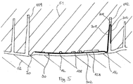
- Figure 5 shows a sectional view through the airbag arrangement of Figure 4 along line A-A.
- the view of Figure 4 is a view into the chute of the airbag arrangement, quasi from the perspective of the airbag.
- the opposite walls 182, 184 can be seen, which, together with the opposite walls 186, 188, enclose the chute.
- the airbag flap 12 closes the chute and, in the example of Figures 4 and 5 , is illustrated to include ribs 128 and recesses for stabilizing the airbag flap 12.
- the material web 30 extends on the inner side of the chute wall 182 and along the inner side of the flap 12, wherein the reinforcing ribs 128 of the flap 12 are at least partially formed above the material web 30, so that the material web 30 is located between the main body of the flap 12 and the ribs 128, as can be best seen in Figure 5 .
- the hinge area 16 and the predetermined breaking line 20 can also be seen in Figure 5 .
- the material web 30 extends with its first section 302 across the inner side of the flap 12, across the hinge area 16, and with its second section 304 along the inner side of the wall 182.
- the edgefolding 308 inside the wall 182 as well as the third section 306 of the material web 30 can be seen as well.
- Mold halves of an injection mold for manufacturing the airbag arrangement are schematically shown in Figure 5 by means of the hatchings S1 and S2.
- the nozzle side or molding side of an injection molding tool can be located on the side of the flap 12 and the wall 182 facing away from the material web (in the hatching S1), so that the material web 30 is pushed against the opposite surface of the injection mold by means of the injected material, and is thus embedded in the corresponding surfaces of the flap 12 and of the wall 182.
- the injected material inside the mold cavity, in which the wall 182 is formed thereby penetrates between the sections 304 and 306 of the material web, on both sides of the edgefolding 308, so that the material web 30 comes to rest on the two opposite surfaces of the wall 182 and is anchored in the wall 182 by means of the injected material.
- the ejector side of the injection mold is located on the opposite side of the mold, which is suggested by the hatching S2.
- the edgefolding 308 can be prefixed.
- a mold comprising a first mold shell and a second mold shell can thus be used to manufacture the airbag arrangement, the mold shells configured to integrally mold a flap, which closes a passage opening for an airbag, a hinge section along a side of the flap and a chute, which is connected to the flap via the hinge section.
- the material web is placed into the mold in such a way that a first part of the material web comes to rest on a first surface section of the mold, which is configured to form a surface of the flap facing the airbag, a second part of the material web comes to rest on a second surface section of the mold, which is configured to form an adjoining surface of the chute component, and a third part of the material web comes to rest on a third surface section of the mold, which is configured to form an opposite surface of the chute wall.
- plastic material is introduced into the closed mold, e.g. injected, wherein the first, the second, and the third part of the material web are pushed against the first, the second and the third surface section.
- the material web comprise a textile or a fabric, a knitted fabric, a film, a metal layer or a combination thereof, wherein the material web can further include natural and/or synthetic fibers.
- the material web can be expandable at least in a first direction, which extends perpendicular or approximately perpendicular to the hinge section.
Landscapes
- Engineering & Computer Science (AREA)
- Mechanical Engineering (AREA)
- Manufacturing & Machinery (AREA)
- Air Bags (AREA)
Applications Claiming Priority (1)
| Application Number | Priority Date | Filing Date | Title |
|---|---|---|---|
| DE102017100330.4A DE102017100330A1 (de) | 2017-01-10 | 2017-01-10 | Airbag-Anordnung und Verfahren zu ihrer Herstellung |
Publications (2)
| Publication Number | Publication Date |
|---|---|
| EP3345794A1 true EP3345794A1 (de) | 2018-07-11 |
| EP3345794B1 EP3345794B1 (de) | 2019-06-12 |
Family
ID=60781949
Family Applications (1)
| Application Number | Title | Priority Date | Filing Date |
|---|---|---|---|
| EP17209724.8A Active EP3345794B1 (de) | 2017-01-10 | 2017-12-21 | Airbaganordnung und verfahren zur herstellung davon |
Country Status (3)
| Country | Link |
|---|---|
| US (1) | US11117541B2 (de) |
| EP (1) | EP3345794B1 (de) |
| DE (1) | DE102017100330A1 (de) |
Cited By (3)
| Publication number | Priority date | Publication date | Assignee | Title |
|---|---|---|---|---|
| EP3730354A1 (de) * | 2019-04-24 | 2020-10-28 | Faurecia Intérieur Industrie | Airbagsystem für ein fahrzeug und verfahren zur herstellung des airbagsystems |
| US11440498B2 (en) * | 2018-08-24 | 2022-09-13 | Riedel Communications International GmbH | Airbag cover |
| US11524651B2 (en) * | 2018-08-24 | 2022-12-13 | K.L. Kaschier-Und Laminier Gmbh | Airbag cover |
Families Citing this family (8)
| Publication number | Priority date | Publication date | Assignee | Title |
|---|---|---|---|---|
| CN108725371B (zh) * | 2017-04-19 | 2021-07-13 | 福特环球技术公司 | 具有径向肋模式的乘客气囊滑槽通道 |
| DE102018006703A1 (de) * | 2018-08-24 | 2020-02-27 | K.L. Kaschier- Und Laminier Gmbh | Airbaganordnung |
| KR102638696B1 (ko) * | 2018-09-06 | 2024-02-21 | 현대모비스 주식회사 | 승객용 에어백의 슈트 |
| CN111267302A (zh) * | 2020-02-10 | 2020-06-12 | 宁波方正汽车模具股份有限公司 | 汽车安全气囊盖顶出机构 |
| DE102020104716A1 (de) | 2020-02-24 | 2021-08-26 | K. L. Kaschier- Und Laminier Gmbh | Abdeckung eines Airbagschusskanals |
| KR102452475B1 (ko) * | 2020-08-26 | 2022-10-11 | 현대모비스 주식회사 | 차량용 운전석 에어백 장치 |
| DE102022110150A1 (de) | 2022-04-27 | 2023-11-02 | Bayerische Motoren Werke Aktiengesellschaft | Werkzeug und Verfahren zur Herstellung einer Airbag-Anordnung |
| CN115285060B (zh) * | 2022-08-04 | 2023-06-23 | 上海延锋金桥汽车饰件系统有限公司 | 一种气囊门结构 |
Citations (5)
| Publication number | Priority date | Publication date | Assignee | Title |
|---|---|---|---|---|
| US5901976A (en) * | 1996-04-27 | 1999-05-11 | Trw Automotive Safety Systems Gmbh | Airbag lid |
| WO2008087014A1 (de) * | 2007-01-16 | 2008-07-24 | Johnson Controls Interiors Gmbh & Co. Kg | Fahrzeug-ausstattungsteil mit airbagaustrittsdeckel |
| EP2193960A1 (de) * | 2008-12-05 | 2010-06-09 | Peguform GmbH | Modular aufgebautes Innenverkleidungsbauteil mit einem Schusskanalmodul für einen Airbag |
| US20120126514A1 (en) * | 2010-11-22 | 2012-05-24 | Hyundai Mobis Co., Ltd. | Passenger air-bag door |
| US20140375029A1 (en) * | 2013-06-24 | 2014-12-25 | Faurecia Interieur Industrie | Safety Device for Vehicle |
Family Cites Families (11)
| Publication number | Priority date | Publication date | Assignee | Title |
|---|---|---|---|---|
| FR2838682B1 (fr) * | 2002-04-18 | 2004-05-28 | Faurecia Interieur Ind | Procede de fabrication d'une partie de planche de bord equipee d'un coussin gonflable |
| EP1752341A1 (de) | 2005-08-11 | 2007-02-14 | Peguform Bohemia k.s. | Gassackabdeckung im Instrumententafel |
| US9889813B2 (en) * | 2006-12-07 | 2018-02-13 | Inoac Usa, Inc. | Apparatus for pressure bonding of a covering on an automotive interior component and a method for pressure bonding thereof |
| DE102007035073A1 (de) * | 2007-07-26 | 2009-02-12 | Lisa Dräxlmaier GmbH | Gewirke mit Einlegefäden für Airbagklappe |
| DE102007053995B4 (de) | 2007-11-13 | 2016-12-22 | Volkswagen Ag | Verfahren zur Herstellung einer Instrumententafel eines Kraftfahrzeugs |
| KR101382329B1 (ko) * | 2012-09-19 | 2014-04-08 | 현대자동차 주식회사 | 자동차의 에어백 하우징 및 그 제조방법 |
| DE102012021315A1 (de) | 2012-10-31 | 2014-04-30 | K.L. Kaschier- Und Laminier Gmbh | Airbag-Abdeckung mit mindestens einer Klappe |
| FR3007347B1 (fr) * | 2013-06-24 | 2017-02-24 | Faurecia Interieur Ind | Procede pour mouler par injection un boitier de coussin de securite gonflable. |
| FR3007350B1 (fr) * | 2013-06-24 | 2015-06-05 | Faurecia Interieur Ind | Dispositif de securite pour vehicule. |
| EP3034361B1 (de) * | 2014-12-16 | 2018-04-18 | Volvo Car Corporation | Airbagabdeckung und Herstellungsverfahren für eine Airbagabdeckung |
| DE102015001103A1 (de) | 2015-01-30 | 2016-08-04 | K.L. Kaschier- Und Laminier Gmbh | Verbundwerkstoff für eine Airbagabdeckung |
-
2017
- 2017-01-10 DE DE102017100330.4A patent/DE102017100330A1/de active Pending
- 2017-12-21 EP EP17209724.8A patent/EP3345794B1/de active Active
-
2018
- 2018-01-05 US US15/863,629 patent/US11117541B2/en active Active
Patent Citations (5)
| Publication number | Priority date | Publication date | Assignee | Title |
|---|---|---|---|---|
| US5901976A (en) * | 1996-04-27 | 1999-05-11 | Trw Automotive Safety Systems Gmbh | Airbag lid |
| WO2008087014A1 (de) * | 2007-01-16 | 2008-07-24 | Johnson Controls Interiors Gmbh & Co. Kg | Fahrzeug-ausstattungsteil mit airbagaustrittsdeckel |
| EP2193960A1 (de) * | 2008-12-05 | 2010-06-09 | Peguform GmbH | Modular aufgebautes Innenverkleidungsbauteil mit einem Schusskanalmodul für einen Airbag |
| US20120126514A1 (en) * | 2010-11-22 | 2012-05-24 | Hyundai Mobis Co., Ltd. | Passenger air-bag door |
| US20140375029A1 (en) * | 2013-06-24 | 2014-12-25 | Faurecia Interieur Industrie | Safety Device for Vehicle |
Cited By (4)
| Publication number | Priority date | Publication date | Assignee | Title |
|---|---|---|---|---|
| US11440498B2 (en) * | 2018-08-24 | 2022-09-13 | Riedel Communications International GmbH | Airbag cover |
| US11524651B2 (en) * | 2018-08-24 | 2022-12-13 | K.L. Kaschier-Und Laminier Gmbh | Airbag cover |
| EP3730354A1 (de) * | 2019-04-24 | 2020-10-28 | Faurecia Intérieur Industrie | Airbagsystem für ein fahrzeug und verfahren zur herstellung des airbagsystems |
| US11351944B2 (en) | 2019-04-24 | 2022-06-07 | Faurecia Interieur Industrie | Airbag system for a vehicle and method for manufacturing the airbag system |
Also Published As
| Publication number | Publication date |
|---|---|
| US20180194319A1 (en) | 2018-07-12 |
| DE102017100330A1 (de) | 2018-07-12 |
| US11117541B2 (en) | 2021-09-14 |
| EP3345794B1 (de) | 2019-06-12 |
Similar Documents
| Publication | Publication Date | Title |
|---|---|---|
| EP3345794B1 (de) | Airbaganordnung und verfahren zur herstellung davon | |
| US9045106B2 (en) | Safety device for vehicle | |
| US9010799B2 (en) | Molding in airbag door features in a vehicle interior panel using a movable mold member | |
| EP3034361A1 (de) | Airbagabdeckung und Herstellungsverfahren für eine Airbagabdeckung | |
| US9022419B2 (en) | Safety device for vehicle | |
| US11351944B2 (en) | Airbag system for a vehicle and method for manufacturing the airbag system | |
| CN101678811B (zh) | 汽车的具有整合的气囊封盖的内空间衬里及其制造方法 | |
| US7631890B1 (en) | Invisible molded-in tear seam and hinge for an airbag deployment door | |
| US20140375026A1 (en) | Method for Injection Molding of an Airbag Case | |
| EP2703232B1 (de) | Verkleidungsbauteil mit Einlegeteil zur Abdeckung eines Airbags sowie Herstellungsverfahren für das Innenverkleidungsbauteil | |
| KR101776465B1 (ko) | 일체형 크래쉬패드 및 그 제조방법 | |
| US9623827B2 (en) | Instrument panel with an airbag flap | |
| US11485310B2 (en) | Airbag system for a vehicle and method for manufacturing the airbag system | |
| KR102638696B1 (ko) | 승객용 에어백의 슈트 | |
| CN111448104A (zh) | 气囊的盖组件 | |
| KR100439920B1 (ko) | 하드 패널을 통하여 에어백을 전개하는 장치 | |
| EP1754635A1 (de) | Instrumententafel mit integriertem Gassackabdeckung und Herstellungsverfahren dafür | |
| DE10223302A1 (de) | Airbagabdeckung | |
| JP6563082B1 (ja) | エアバッグリッド補強部材及びその製造方法 | |
| CN211918604U (zh) | 车辆内饰面板 | |
| EP3401086A1 (de) | Beifahrerseitiges airbaggehäuse, herstellungsverfahren dafür und beifahrerseitiger airbag für ein fahrzeug | |
| JP6433816B2 (ja) | エアバッグ装置のカバー体 | |
| KR20090033473A (ko) | 에어백을 구비하는 인스트루먼트 패널 및 그 제조방법 | |
| KR100710454B1 (ko) | 인비저블 에어백 도어구조 및 그 제조방법 | |
| JP5929724B2 (ja) | エアバッグカバーとその製造方法 |
Legal Events
| Date | Code | Title | Description |
|---|---|---|---|
| PUAI | Public reference made under article 153(3) epc to a published international application that has entered the european phase |
Free format text: ORIGINAL CODE: 0009012 |
|
| STAA | Information on the status of an ep patent application or granted ep patent |
Free format text: STATUS: THE APPLICATION HAS BEEN PUBLISHED |
|
| AK | Designated contracting states |
Kind code of ref document: A1 Designated state(s): AL AT BE BG CH CY CZ DE DK EE ES FI FR GB GR HR HU IE IS IT LI LT LU LV MC MK MT NL NO PL PT RO RS SE SI SK SM TR |
|
| AX | Request for extension of the european patent |
Extension state: BA ME |
|
| STAA | Information on the status of an ep patent application or granted ep patent |
Free format text: STATUS: REQUEST FOR EXAMINATION WAS MADE |
|
| 17P | Request for examination filed |
Effective date: 20181221 |
|
| RBV | Designated contracting states (corrected) |
Designated state(s): AL AT BE BG CH CY CZ DE DK EE ES FI FR GB GR HR HU IE IS IT LI LT LU LV MC MK MT NL NO PL PT RO RS SE SI SK SM TR |
|
| GRAP | Despatch of communication of intention to grant a patent |
Free format text: ORIGINAL CODE: EPIDOSNIGR1 |
|
| STAA | Information on the status of an ep patent application or granted ep patent |
Free format text: STATUS: GRANT OF PATENT IS INTENDED |
|
| RIC1 | Information provided on ipc code assigned before grant |
Ipc: B60R 21/215 20110101AFI20190118BHEP Ipc: B29C 45/14 20060101ALI20190118BHEP Ipc: B29C 45/16 20060101ALI20190118BHEP |
|
| INTG | Intention to grant announced |
Effective date: 20190211 |
|
| GRAS | Grant fee paid |
Free format text: ORIGINAL CODE: EPIDOSNIGR3 |
|
| GRAA | (expected) grant |
Free format text: ORIGINAL CODE: 0009210 |
|
| STAA | Information on the status of an ep patent application or granted ep patent |
Free format text: STATUS: THE PATENT HAS BEEN GRANTED |
|
| AK | Designated contracting states |
Kind code of ref document: B1 Designated state(s): AL AT BE BG CH CY CZ DE DK EE ES FI FR GB GR HR HU IE IS IT LI LT LU LV MC MK MT NL NO PL PT RO RS SE SI SK SM TR |
|
| REG | Reference to a national code |
Ref country code: GB Ref legal event code: FG4D |
|
| REG | Reference to a national code |
Ref country code: CH Ref legal event code: EP |
|
| REG | Reference to a national code |
Ref country code: AT Ref legal event code: REF Ref document number: 1142144 Country of ref document: AT Kind code of ref document: T Effective date: 20190615 |
|
| REG | Reference to a national code |
Ref country code: DE Ref legal event code: R096 Ref document number: 602017004494 Country of ref document: DE |
|
| REG | Reference to a national code |
Ref country code: IE Ref legal event code: FG4D |
|
| REG | Reference to a national code |
Ref country code: NL Ref legal event code: MP Effective date: 20190612 |
|
| REG | Reference to a national code |
Ref country code: LT Ref legal event code: MG4D |
|
| PG25 | Lapsed in a contracting state [announced via postgrant information from national office to epo] |
Ref country code: SE Free format text: LAPSE BECAUSE OF FAILURE TO SUBMIT A TRANSLATION OF THE DESCRIPTION OR TO PAY THE FEE WITHIN THE PRESCRIBED TIME-LIMIT Effective date: 20190612 Ref country code: LT Free format text: LAPSE BECAUSE OF FAILURE TO SUBMIT A TRANSLATION OF THE DESCRIPTION OR TO PAY THE FEE WITHIN THE PRESCRIBED TIME-LIMIT Effective date: 20190612 Ref country code: FI Free format text: LAPSE BECAUSE OF FAILURE TO SUBMIT A TRANSLATION OF THE DESCRIPTION OR TO PAY THE FEE WITHIN THE PRESCRIBED TIME-LIMIT Effective date: 20190612 Ref country code: AL Free format text: LAPSE BECAUSE OF FAILURE TO SUBMIT A TRANSLATION OF THE DESCRIPTION OR TO PAY THE FEE WITHIN THE PRESCRIBED TIME-LIMIT Effective date: 20190612 Ref country code: NO Free format text: LAPSE BECAUSE OF FAILURE TO SUBMIT A TRANSLATION OF THE DESCRIPTION OR TO PAY THE FEE WITHIN THE PRESCRIBED TIME-LIMIT Effective date: 20190912 Ref country code: HR Free format text: LAPSE BECAUSE OF FAILURE TO SUBMIT A TRANSLATION OF THE DESCRIPTION OR TO PAY THE FEE WITHIN THE PRESCRIBED TIME-LIMIT Effective date: 20190612 |
|
| PG25 | Lapsed in a contracting state [announced via postgrant information from national office to epo] |
Ref country code: GR Free format text: LAPSE BECAUSE OF FAILURE TO SUBMIT A TRANSLATION OF THE DESCRIPTION OR TO PAY THE FEE WITHIN THE PRESCRIBED TIME-LIMIT Effective date: 20190913 Ref country code: LV Free format text: LAPSE BECAUSE OF FAILURE TO SUBMIT A TRANSLATION OF THE DESCRIPTION OR TO PAY THE FEE WITHIN THE PRESCRIBED TIME-LIMIT Effective date: 20190612 Ref country code: RS Free format text: LAPSE BECAUSE OF FAILURE TO SUBMIT A TRANSLATION OF THE DESCRIPTION OR TO PAY THE FEE WITHIN THE PRESCRIBED TIME-LIMIT Effective date: 20190612 Ref country code: BG Free format text: LAPSE BECAUSE OF FAILURE TO SUBMIT A TRANSLATION OF THE DESCRIPTION OR TO PAY THE FEE WITHIN THE PRESCRIBED TIME-LIMIT Effective date: 20190912 |
|
| REG | Reference to a national code |
Ref country code: AT Ref legal event code: MK05 Ref document number: 1142144 Country of ref document: AT Kind code of ref document: T Effective date: 20190612 |
|
| PG25 | Lapsed in a contracting state [announced via postgrant information from national office to epo] |
Ref country code: NL Free format text: LAPSE BECAUSE OF FAILURE TO SUBMIT A TRANSLATION OF THE DESCRIPTION OR TO PAY THE FEE WITHIN THE PRESCRIBED TIME-LIMIT Effective date: 20190612 Ref country code: AT Free format text: LAPSE BECAUSE OF FAILURE TO SUBMIT A TRANSLATION OF THE DESCRIPTION OR TO PAY THE FEE WITHIN THE PRESCRIBED TIME-LIMIT Effective date: 20190612 Ref country code: EE Free format text: LAPSE BECAUSE OF FAILURE TO SUBMIT A TRANSLATION OF THE DESCRIPTION OR TO PAY THE FEE WITHIN THE PRESCRIBED TIME-LIMIT Effective date: 20190612 Ref country code: PT Free format text: LAPSE BECAUSE OF FAILURE TO SUBMIT A TRANSLATION OF THE DESCRIPTION OR TO PAY THE FEE WITHIN THE PRESCRIBED TIME-LIMIT Effective date: 20191014 Ref country code: CZ Free format text: LAPSE BECAUSE OF FAILURE TO SUBMIT A TRANSLATION OF THE DESCRIPTION OR TO PAY THE FEE WITHIN THE PRESCRIBED TIME-LIMIT Effective date: 20190612 Ref country code: RO Free format text: LAPSE BECAUSE OF FAILURE TO SUBMIT A TRANSLATION OF THE DESCRIPTION OR TO PAY THE FEE WITHIN THE PRESCRIBED TIME-LIMIT Effective date: 20190612 Ref country code: SK Free format text: LAPSE BECAUSE OF FAILURE TO SUBMIT A TRANSLATION OF THE DESCRIPTION OR TO PAY THE FEE WITHIN THE PRESCRIBED TIME-LIMIT Effective date: 20190612 |
|
| PG25 | Lapsed in a contracting state [announced via postgrant information from national office to epo] |
Ref country code: ES Free format text: LAPSE BECAUSE OF FAILURE TO SUBMIT A TRANSLATION OF THE DESCRIPTION OR TO PAY THE FEE WITHIN THE PRESCRIBED TIME-LIMIT Effective date: 20190612 Ref country code: SM Free format text: LAPSE BECAUSE OF FAILURE TO SUBMIT A TRANSLATION OF THE DESCRIPTION OR TO PAY THE FEE WITHIN THE PRESCRIBED TIME-LIMIT Effective date: 20190612 Ref country code: IS Free format text: LAPSE BECAUSE OF FAILURE TO SUBMIT A TRANSLATION OF THE DESCRIPTION OR TO PAY THE FEE WITHIN THE PRESCRIBED TIME-LIMIT Effective date: 20191012 Ref country code: IT Free format text: LAPSE BECAUSE OF FAILURE TO SUBMIT A TRANSLATION OF THE DESCRIPTION OR TO PAY THE FEE WITHIN THE PRESCRIBED TIME-LIMIT Effective date: 20190612 |
|
| REG | Reference to a national code |
Ref country code: DE Ref legal event code: R026 Ref document number: 602017004494 Country of ref document: DE |
|
| PLBI | Opposition filed |
Free format text: ORIGINAL CODE: 0009260 |
|
| PG25 | Lapsed in a contracting state [announced via postgrant information from national office to epo] |
Ref country code: TR Free format text: LAPSE BECAUSE OF FAILURE TO SUBMIT A TRANSLATION OF THE DESCRIPTION OR TO PAY THE FEE WITHIN THE PRESCRIBED TIME-LIMIT Effective date: 20190612 |
|
| 26 | Opposition filed |
Opponent name: K.L. KASCHIER- UND LAMINIER GMBH Effective date: 20200312 |
|
| PLAX | Notice of opposition and request to file observation + time limit sent |
Free format text: ORIGINAL CODE: EPIDOSNOBS2 |
|
| PG25 | Lapsed in a contracting state [announced via postgrant information from national office to epo] |
Ref country code: DK Free format text: LAPSE BECAUSE OF FAILURE TO SUBMIT A TRANSLATION OF THE DESCRIPTION OR TO PAY THE FEE WITHIN THE PRESCRIBED TIME-LIMIT Effective date: 20190612 Ref country code: PL Free format text: LAPSE BECAUSE OF FAILURE TO SUBMIT A TRANSLATION OF THE DESCRIPTION OR TO PAY THE FEE WITHIN THE PRESCRIBED TIME-LIMIT Effective date: 20190612 |
|
| PLAF | Information modified related to communication of a notice of opposition and request to file observations + time limit |
Free format text: ORIGINAL CODE: EPIDOSCOBS2 |
|
| PG25 | Lapsed in a contracting state [announced via postgrant information from national office to epo] |
Ref country code: IS Free format text: LAPSE BECAUSE OF FAILURE TO SUBMIT A TRANSLATION OF THE DESCRIPTION OR TO PAY THE FEE WITHIN THE PRESCRIBED TIME-LIMIT Effective date: 20200224 |
|
| PG2D | Information on lapse in contracting state deleted |
Ref country code: IS |
|
| REG | Reference to a national code |
Ref country code: BE Ref legal event code: MM Effective date: 20191231 |
|
| PG25 | Lapsed in a contracting state [announced via postgrant information from national office to epo] |
Ref country code: MC Free format text: LAPSE BECAUSE OF FAILURE TO SUBMIT A TRANSLATION OF THE DESCRIPTION OR TO PAY THE FEE WITHIN THE PRESCRIBED TIME-LIMIT Effective date: 20190612 |
|
| PLBB | Reply of patent proprietor to notice(s) of opposition received |
Free format text: ORIGINAL CODE: EPIDOSNOBS3 |
|
| PG25 | Lapsed in a contracting state [announced via postgrant information from national office to epo] |
Ref country code: FR Free format text: LAPSE BECAUSE OF NON-PAYMENT OF DUE FEES Effective date: 20191231 Ref country code: LU Free format text: LAPSE BECAUSE OF NON-PAYMENT OF DUE FEES Effective date: 20191221 Ref country code: IE Free format text: LAPSE BECAUSE OF NON-PAYMENT OF DUE FEES Effective date: 20191221 |
|
| PG25 | Lapsed in a contracting state [announced via postgrant information from national office to epo] |
Ref country code: BE Free format text: LAPSE BECAUSE OF NON-PAYMENT OF DUE FEES Effective date: 20191231 |
|
| PG25 | Lapsed in a contracting state [announced via postgrant information from national office to epo] |
Ref country code: CY Free format text: LAPSE BECAUSE OF FAILURE TO SUBMIT A TRANSLATION OF THE DESCRIPTION OR TO PAY THE FEE WITHIN THE PRESCRIBED TIME-LIMIT Effective date: 20190612 |
|
| PG25 | Lapsed in a contracting state [announced via postgrant information from national office to epo] |
Ref country code: HU Free format text: LAPSE BECAUSE OF FAILURE TO SUBMIT A TRANSLATION OF THE DESCRIPTION OR TO PAY THE FEE WITHIN THE PRESCRIBED TIME-LIMIT; INVALID AB INITIO Effective date: 20171221 Ref country code: MT Free format text: LAPSE BECAUSE OF FAILURE TO SUBMIT A TRANSLATION OF THE DESCRIPTION OR TO PAY THE FEE WITHIN THE PRESCRIBED TIME-LIMIT Effective date: 20190612 |
|
| REG | Reference to a national code |
Ref country code: CH Ref legal event code: PL |
|
| PG25 | Lapsed in a contracting state [announced via postgrant information from national office to epo] |
Ref country code: SI Free format text: LAPSE BECAUSE OF FAILURE TO SUBMIT A TRANSLATION OF THE DESCRIPTION OR TO PAY THE FEE WITHIN THE PRESCRIBED TIME-LIMIT Effective date: 20190612 |
|
| PG25 | Lapsed in a contracting state [announced via postgrant information from national office to epo] |
Ref country code: CH Free format text: LAPSE BECAUSE OF NON-PAYMENT OF DUE FEES Effective date: 20201231 Ref country code: LI Free format text: LAPSE BECAUSE OF NON-PAYMENT OF DUE FEES Effective date: 20201231 |
|
| APBM | Appeal reference recorded |
Free format text: ORIGINAL CODE: EPIDOSNREFNO |
|
| APBP | Date of receipt of notice of appeal recorded |
Free format text: ORIGINAL CODE: EPIDOSNNOA2O |
|
| APAH | Appeal reference modified |
Free format text: ORIGINAL CODE: EPIDOSCREFNO |
|
| APBM | Appeal reference recorded |
Free format text: ORIGINAL CODE: EPIDOSNREFNO |
|
| APBP | Date of receipt of notice of appeal recorded |
Free format text: ORIGINAL CODE: EPIDOSNNOA2O |
|
| PG25 | Lapsed in a contracting state [announced via postgrant information from national office to epo] |
Ref country code: MK Free format text: LAPSE BECAUSE OF FAILURE TO SUBMIT A TRANSLATION OF THE DESCRIPTION OR TO PAY THE FEE WITHIN THE PRESCRIBED TIME-LIMIT Effective date: 20190612 |
|
| APBQ | Date of receipt of statement of grounds of appeal recorded |
Free format text: ORIGINAL CODE: EPIDOSNNOA3O |
|
| GBPC | Gb: european patent ceased through non-payment of renewal fee |
Effective date: 20211221 |
|
| PG25 | Lapsed in a contracting state [announced via postgrant information from national office to epo] |
Ref country code: GB Free format text: LAPSE BECAUSE OF NON-PAYMENT OF DUE FEES Effective date: 20211221 |
|
| APBU | Appeal procedure closed |
Free format text: ORIGINAL CODE: EPIDOSNNOA9O |
|
| PGFP | Annual fee paid to national office [announced via postgrant information from national office to epo] |
Ref country code: DE Payment date: 20240228 Year of fee payment: 7 |
|
| PLAY | Examination report in opposition despatched + time limit |
Free format text: ORIGINAL CODE: EPIDOSNORE2 |