EP3344111B1 - Instrument à tige, en particulier instrument médical d'endoscopie à tige - Google Patents
Instrument à tige, en particulier instrument médical d'endoscopie à tige Download PDFInfo
- Publication number
- EP3344111B1 EP3344111B1 EP16812670.4A EP16812670A EP3344111B1 EP 3344111 B1 EP3344111 B1 EP 3344111B1 EP 16812670 A EP16812670 A EP 16812670A EP 3344111 B1 EP3344111 B1 EP 3344111B1
- Authority
- EP
- European Patent Office
- Prior art keywords
- housing
- shank
- hollow shank
- hollow shaft
- hollow
- Prior art date
- Legal status (The legal status is an assumption and is not a legal conclusion. Google has not performed a legal analysis and makes no representation as to the accuracy of the status listed.)
- Active
Links
- 230000033001 locomotion Effects 0.000 claims description 16
- 230000002093 peripheral effect Effects 0.000 claims description 10
- 238000005286 illumination Methods 0.000 description 7
- 210000000056 organ Anatomy 0.000 description 4
- 239000004065 semiconductor Substances 0.000 description 4
- 238000006073 displacement reaction Methods 0.000 description 3
- 239000012530 fluid Substances 0.000 description 3
- 230000003287 optical effect Effects 0.000 description 3
- 238000011161 development Methods 0.000 description 2
- 230000018109 developmental process Effects 0.000 description 2
- 230000000694 effects Effects 0.000 description 2
- 238000000576 coating method Methods 0.000 description 1
- 230000000295 complement effect Effects 0.000 description 1
- 239000004020 conductor Substances 0.000 description 1
- 230000001419 dependent effect Effects 0.000 description 1
- 238000005516 engineering process Methods 0.000 description 1
- 230000002349 favourable effect Effects 0.000 description 1
- 239000007788 liquid Substances 0.000 description 1
- 238000004519 manufacturing process Methods 0.000 description 1
- 238000002324 minimally invasive surgery Methods 0.000 description 1
- 239000013307 optical fiber Substances 0.000 description 1
Images


Classifications
-
- A—HUMAN NECESSITIES
- A61—MEDICAL OR VETERINARY SCIENCE; HYGIENE
- A61B—DIAGNOSIS; SURGERY; IDENTIFICATION
- A61B1/00—Instruments for performing medical examinations of the interior of cavities or tubes of the body by visual or photographical inspection, e.g. endoscopes; Illuminating arrangements therefor
- A61B1/00064—Constructional details of the endoscope body
- A61B1/00071—Insertion part of the endoscope body
- A61B1/0008—Insertion part of the endoscope body characterised by distal tip features
- A61B1/00096—Optical elements
-
- A—HUMAN NECESSITIES
- A61—MEDICAL OR VETERINARY SCIENCE; HYGIENE
- A61B—DIAGNOSIS; SURGERY; IDENTIFICATION
- A61B1/00—Instruments for performing medical examinations of the interior of cavities or tubes of the body by visual or photographical inspection, e.g. endoscopes; Illuminating arrangements therefor
- A61B1/00163—Optical arrangements
- A61B1/00174—Optical arrangements characterised by the viewing angles
- A61B1/00183—Optical arrangements characterised by the viewing angles for variable viewing angles
-
- A—HUMAN NECESSITIES
- A61—MEDICAL OR VETERINARY SCIENCE; HYGIENE
- A61B—DIAGNOSIS; SURGERY; IDENTIFICATION
- A61B1/00—Instruments for performing medical examinations of the interior of cavities or tubes of the body by visual or photographical inspection, e.g. endoscopes; Illuminating arrangements therefor
- A61B1/04—Instruments for performing medical examinations of the interior of cavities or tubes of the body by visual or photographical inspection, e.g. endoscopes; Illuminating arrangements therefor combined with photographic or television appliances
- A61B1/05—Instruments for performing medical examinations of the interior of cavities or tubes of the body by visual or photographical inspection, e.g. endoscopes; Illuminating arrangements therefor combined with photographic or television appliances characterised by the image sensor, e.g. camera, being in the distal end portion
-
- A—HUMAN NECESSITIES
- A61—MEDICAL OR VETERINARY SCIENCE; HYGIENE
- A61B—DIAGNOSIS; SURGERY; IDENTIFICATION
- A61B1/00—Instruments for performing medical examinations of the interior of cavities or tubes of the body by visual or photographical inspection, e.g. endoscopes; Illuminating arrangements therefor
- A61B1/06—Instruments for performing medical examinations of the interior of cavities or tubes of the body by visual or photographical inspection, e.g. endoscopes; Illuminating arrangements therefor with illuminating arrangements
- A61B1/0661—Endoscope light sources
- A61B1/0684—Endoscope light sources using light emitting diodes [LED]
-
- A—HUMAN NECESSITIES
- A61—MEDICAL OR VETERINARY SCIENCE; HYGIENE
- A61B—DIAGNOSIS; SURGERY; IDENTIFICATION
- A61B1/00—Instruments for performing medical examinations of the interior of cavities or tubes of the body by visual or photographical inspection, e.g. endoscopes; Illuminating arrangements therefor
- A61B1/012—Instruments for performing medical examinations of the interior of cavities or tubes of the body by visual or photographical inspection, e.g. endoscopes; Illuminating arrangements therefor characterised by internal passages or accessories therefor
- A61B1/018—Instruments for performing medical examinations of the interior of cavities or tubes of the body by visual or photographical inspection, e.g. endoscopes; Illuminating arrangements therefor characterised by internal passages or accessories therefor for receiving instruments
Definitions
- the invention relates to a shaft instrument and in particular a medical-endoscopic shaft instrument.
- these shaft instruments have an observation device and a lighting device for illuminating the observation region.
- the observation devices used are either lens systems extending from the distal end of the shaft through the shaft and connected to eyepieces on the proximal side of the shaft or electronic video camera video camera sensors located at the distal end of the shaft, the image sensors having an image data processing device arranged on the proximal side of the shaft and a downstream of this device viewing device are connected.
- the illumination devices either comprise at least one guided by the shaft and connected to a light source on the proximal side of the shaft Optical fiber or at least one arranged on the distal end of the shaft semiconductor light-emitting element, which is connected to a voltage source arranged on the proximal side of the shaft.
- the starting point of the invention is formed by such shaft instruments which, in addition to optical observation, also enable the carrying out of operative interventions in the observation area.
- auxiliary instruments such as forceps or cutting instruments are guided to the surgical site through the hollow shafted shaft.
- EP 2123225 A1 Although it is the state of the art to drive out a camera housing arranged in the region of the distal end of the shaft from the inner lumen of the shaft, it only excludes it optical reasons, to obtain a more favorable for the intervention observation position. The working channel is not affected by this, the extension mechanism is complex, space consuming and vulnerable.
- the invention has for its object to provide a shaft instrument and in particular a medical-endoscopic shaft instrument, which does not have the disadvantages described above.
- the shank instrument according to the invention is preferably a medical-endoscopic shank instrument, but it can also be a technoscope used in the technical field.
- the shank instrument is equipped with a hollow shaft through which, if necessary, an auxiliary instrument and / or a fluid can be guided to the distal side of the hollow shaft.
- the hollow shaft may be designed to be flexibly flexible both in a rigid manner and at least in sections in the direction transverse to its longitudinal extent.
- the shaft instrument has at least one electronic image sensor and luminous means, wherein the at least one image sensor serves to optically detect a region located distally on the hollow shaft and the luminous means are provided to illuminate this region detected by the image sensor.
- All known electronic image sensors can be used as the image sensor, image sensors designed as semiconductor chips, such as, for example, CMOS sensors or CCD sensors, being preferred because of their small size.
- the light-emitting means preferably semiconductor light-emitting elements, such as light-emitting diodes or laser diodes are provided, which are likewise distinguished by their small size.
- the at least one image sensor and / or the luminous means are arranged in a housing integrated distally in the hollow shaft, wherein the term "housing" is to be understood according to the invention as any enclosures surrounding the image sensor or the illuminants on the outside, ie also simple coatings .
- an image sensor arranged therein is signal-connected to an image data processing device preferably arranged on the proximal side of the hollow shaft, which in turn is in signal connection with a viewing device.
- the illuminants provided for illumination are conductively connected via current conductors guided through the hollow shaft to a voltage source which is likewise arranged on the proximal side of the hollow shaft.
- both an image sensor and at least one light-emitting semiconductor element are arranged as a light source in a common housing.
- the shank instrument according to the invention is characterized in that the housing with the image sensor arranged therein and / or the illuminants arranged therein is movable from a position in which the image sensor and / or the luminous means within the inner lumen of the hollow shaft, that is, are arranged within the clearance space profile, is linearly movable into a position in which the image sensor and / or the lighting means are arranged outside the inner lumen of the hollow shaft.
- Inner lumen in the sense of the present invention is to be understood as meaning the volume enclosed by the shaft, that is to say that determined by its inner contour.
- the shank instrument may thus have a first operating state, in which the housing is arranged completely within the outer profile of the hollow shaft, and from there be transferred by a linear displacement of the housing in a second operating state, in which the housing arranged for the most part laterally outside of the hollow shaft is.
- a first operating state in which the housing is arranged completely within the outer profile of the hollow shaft, and from there be transferred by a linear displacement of the housing in a second operating state, in which the housing arranged for the most part laterally outside of the hollow shaft is.
- the hollow shaft of the shaft instrument In its first operating state, the hollow shaft of the shaft instrument can be guided over its comparatively narrow supply channels to its destination in a hollow organ or cavity, wherein the region distal side of the hollow shaft by means of the image sensor and / or the bulbs, which are then arranged within the inner lumen of the hollow shaft, observe and / or illuminate.
- the housing in a linear movement, preferably in the radial direction of the hollow shaft but possibly also obliquely to the longitudinal extent of the hollow shaft as far as possible be moved out of the inner lumen of the hollow shaft, which also observation and / or illumination of the region is ensured on the distal side of the hollow shaft and especially
- the free space for performing an auxiliary instrument or for conducting a fluid through the hollow shaft is considerably increased. This increases the range of auxiliary instruments that can be used in conjunction with the shaft instrument, or it opens up the possibility of the radial dimensions of the hollow shaft of the shaft instrument without limiting the range of auxiliary instruments previously used to decrease.
- the rectilinear movability of the housing is advantageous insofar as it is simple to realize structurally and in terms of manufacturing technology and results in the image sensor and / or the illumination means always being the same, that is to say without an angle change, both in the first and in the second operating state of the shaft instrument a central axis of the hollow shaft are aligned.
- an opening is formed on the peripheral wall of the hollow shaft, through which the housing is displaceable.
- the position and dimensions of this opening suitably correspond with the location and dimensions of the housing and possibly with the path of movement of the housing, wherein between the housing and the opening is only a small game, so that the housing and the hollow shaft form a dense unit ,
- the housing according to the invention is supported on its opposite from the opening formed on the peripheral wall of the hollow shaft on at least one elongated carrier guided in the hollow shaft, which extends substantially over the entire length of the hollow shaft and in the region of the proximal end the hollow shaft or proximal side of the hollow shaft is fixed.
- the carrier may be expediently fixed in the region of the proximal end of the hollow shaft in as large a radial distance as possible from the central axis of the hollow shaft.
- the carrier is elastically resilient, so that the carrier is bendable under the action of a corresponding external force in the direction transverse to its longitudinal extent and assumes its original shape after the removal of this force.
- This resilient behavior of the wearer is particularly useful since the wearer is fixedly connected to the housing and thus can follow movement of the housing from within the inner lumen of the hollow shaft to outside the inner lumen and vice versa without damage.
- an outer side of the housing in the position of the housing within the inner lumen of the hollow shaft flush with the outside of the peripheral wall of the hollow shaft is preferably selected so that the arranged within the inner lumen of the hollow shaft housing with the hollow shaft forms a common closed surface.
- a recess extending in the longitudinal direction of the hollow shaft, into which the carrier engages, to be formed on this inner side of the housing which points away from the opening formed on the peripheral wall of the hollow shaft.
- the aim of this measure is that the carrier in the case of moving out of the inner lumen of the hollow shaft housing in the hollow shaft as little as possible or not at all to the size of the then created enlarged clearance for performing an auxiliary instrument.
- the recess is expediently dimensioned such that the carrier in the cross-sectional plane of the hollow shaft does not protrude from the housing.
- the carrier is formed by a flat tube.
- the flat tube is usefully aligned such that the housing is supported on a flat side of the flat tube.
- the flat side of the flat tube is in this case aligned normal to the direction of movement of the housing.
- the cross-sectional shape of the flat tube used as a carrier is generally arbitrary, as long as it has larger dimensions in a certain cross-sectional direction than in a cross-sectional direction normally oriented, it is advantageous if the flat tube has a kidney-shaped cross section.
- the housing for the image sensor and / or the lighting means is preferably supported on a convexly curved flat side of the flat tube, the curvature of which corresponds to the internal cross-sectional contour of the hollow shaft, so that the flat tube engages at least in its distal end section with the housing moved out of the inner lumen of the hollow shaft the inner circumference of the hollow shaft comes flush to the plant and in this way to a small extent on the space required to carry out the auxiliary space within the hollow shaft.
- the concave curved flat side of the kidney-shaped flat tube is in this case facing away from the opening formed on the peripheral wall of the hollow shaft, which also positively affects within the hollow shaft with respect to the largest possible clearance for guided through the hollow shaft auxiliary instruments, since these auxiliary instruments usually a shaft with have a circular cross-section.
- connection lines connected to the image sensor and / or the light-emitting diode are guided through the flat tube to the proximal side of the hollow shaft.
- the flat tube is designed to be closed at its distal end, so that the electrical connection lines are completely shielded by a fluid possibly conducted through the free inner lumen of the hollow shaft.
- these are usefully guided at the greatest possible distance from one another, ie in the direction of the largest cross-sectional width of the flat tube, at a distance from one another.
- additional light sources can advantageously be arranged in the flat tube at its distal end, which effect a particularly bright illumination of the area detected by the image sensor.
- the housing is advantageously coupled in motion via a slide control with a movable in the hollow shaft in the longitudinal direction of the hollow shaft push-pull element.
- a movement of the proximal side of the hollow shaft with an actuator connected to the effect push-pull element in the longitudinal direction of the hollow shaft via the link control in a movement of the housing transversely to the longitudinal direction of the hollow shaft.
- the push-pull element preferably has at least one projection aligned transversely to its direction of movement, which engages in a guide groove formed on an outer side of the housing and running obliquely in the radial direction. If the push-pull element is moved in the longitudinal direction of the hollow shaft, causes the obliquely extending on its outside guide groove and the projection of the push-pull element engaging therein a positively guided movement of the housing in the radial direction transversely to the longitudinal extent of the hollow shaft or transversely to the direction of movement of the push-pull element.
- the push-pull element is formed by a tube, which is usefully designed as thin as possible and one with the inner diameter of the hollow shaft having corresponding outer diameter.
- the auxiliary instrument is guided by the pipe arranged in the hollow shaft through the hollow shaft.
- a longitudinal slot is expediently formed, in which the housing engages for the image sensor and / or the lighting means.
- a projection is formed on the two longitudinal sides of the longitudinal slot. These two projections formed on the longitudinal sides of the longitudinal slot engage in two guide grooves formed in mutually oppositely facing outer sides of the housing.
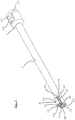
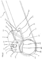
- the shank instruments shown in the drawing each have a hollow shaft 2 formed by a rigid tube, on which a housing part 4 adjoins the proximal side of the hollow shaft 2.
- a housing 8 is integrated in the hollow shaft 2.
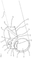
- a recess 12 is formed, in which an image sensor 14 is arranged.
- two further recesses 16 are formed on the end face 10 of the housing 8, in each of which a light-emitting diode 18 is arranged as a light source.
- the image sensor 14 and the light emitting diode 18 are arranged interchangeably, so that the image sensor 14 and the light emitting diodes 18, if necessary can be removed from the housing 18 and can be replaced by another image sensor 14 or by other LEDs 18.
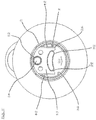
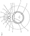
- the housing is of a position in which the image sensor 24 and the light-emitting diodes 8 are arranged inside the inner lumen 22 of the hollow shaft 2 ( Fig. 1 . 3 and 5 ) in a position in which the image sensor 14 and the LEDs 18 are arranged outside the inner lumen 22 of the hollow shaft 2 ( Fig. 2 . 4 . 6 and 7 ).
- an outer side 24 of the housing 8 which has a curvature that is complementary to the outer radius of the hollow shaft 2, is aligned with the outer side of the hollow shaft 2 ,
- a recess 28 is formed at one of the opening 20 and the outer side 24 of the housing 8 facing away from the inner side 26 of the housing 8.
- This recess 28 extends in the longitudinal direction of the hollow shaft 2 from the distal end face 10 to a proximal end face 30 of the housing 8 and serves to receive a flat tube 32 with a kidney-shaped cross section, which extends from the distal end of the hollow shaft 2 to the proximal end of the hollow shaft 2 and is fixed immovably on the housing part 40 on the proximal side of the hollow shaft 2.
- the flat tube 32 forms a support on which the housing 8 is supported both in its position within the inner lumen 22 of the hollow shaft 2 and in its moved out of the inner lumen 22 position.
- the flat tube 32 has a certain elasticity in the direction transverse to its longitudinal extent so that it can be bent elastically transversely to its longitudinal extent.
- the flat tube 32 also serves as a guide channel for connecting to the image sensor 14 and the light emitting diodes 18, not shown in the drawing for clarity, leads through the flat tube 32 to a proximal side of the housing part 4 arranged housing part 52nd are guided, wherein the connected to the image sensor 14 connecting line proximal side of the housing part 52 are connected to an image data processing device, not shown, and connected to the light emitting diodes 18 connecting lines on the proximal side of the housing part 52 to a voltage source, also not shown.
- a voltage source also not shown.
- the flat tube 32 also serves for the arrangement of two additional light-emitting diodes 34, which cause a particularly bright illumination of an area detected by the image sensor 14 distal side of the hollow shaft 2.
- the use of the light emitting diodes 34 is the only difference between the in Fig. 7 Shank instrument shown and in the Fig. 1 - 6
- the flat tube 32 where the light-emitting diodes 34 are arranged, instead of the light-emitting diodes 34 tubes for conducting a rinsing liquid can be used, whereby a "continuous flow" rinsing would be possible.
- a tube 36 is arranged, which extends into the housing part 52.
- the tube 36 is displaceable in the hollow shaft 2 in the longitudinal direction of the hollow shaft 2 and in this way forms a push-pull element.
- a slider 38 fixedly connected to the tube 36 is arranged at its proximal end portion engaging in the housing part 4, which protrudes radially on the outer circumference of the tube 36 and passes through an opening 40 formed circumferentially on the housing part 4.
- the aperture 40 is dimensioned to have a limited displacement the slider 38 in the aperture 40 allows ( Fig. 1 and 2 ).
- the tube 36 serves as an actuating element, with which the housing 8 is movable via a link control from a position in which the image sensor 14 and the light emitting diodes 18 are arranged within the inner lumen 22 of the hollow shaft 2 into a position in which the image sensor 14 and the light emitting diodes 18 are arranged outside the inner lumen 22 of the hollow shaft 2.
- a longitudinal slot 42 is formed on the tube 36, starting from its distal end, which extends to a limited extent in the proximal direction of the tube 36 ( Fig. 3 and 7 ). The width of the longitudinal slot 42 is dimensioned so that the housing 8 can break through the longitudinal slot 42 with little play.
- a projection 46 is formed, which protrudes transversely to the longitudinal extent of the longitudinal slot 42.
- the two projections 46 form sliding blocks, which engage in scenes on the housing 8.
- a guide groove 50 is formed on two normal to the longitudinal slot 42 of the tube 36 aligned outer sides 48 of the housing 8, which, starting from the proximal end of the outer side 24 of the housing 8 obliquely to the distal end of the outer side 26 of the housing 8 extends. In each of the two guide grooves 50 each one of the projections 46 is engaged.
- the engagement of the projections 46 formed on the tube 36 with the obliquely oriented guide grooves 50 of the housing 8 causes the housing 8 to move from a position in which the image sensor 14 and the light-emitting diodes 18 are arranged within the inner lumen 22 of the hollow shaft 2, is moved to a position in which the image sensor 14 and the LEDs 18 arranged outside of the inner lumen 22 of the hollow shaft are.
- the housing 8 is then retracted again into the hollow shaft 2.
Landscapes
- Health & Medical Sciences (AREA)
- Life Sciences & Earth Sciences (AREA)
- Surgery (AREA)
- Physics & Mathematics (AREA)
- Engineering & Computer Science (AREA)
- Optics & Photonics (AREA)
- Biomedical Technology (AREA)
- Molecular Biology (AREA)
- Pathology (AREA)
- Nuclear Medicine, Radiotherapy & Molecular Imaging (AREA)
- Biophysics (AREA)
- Heart & Thoracic Surgery (AREA)
- Medical Informatics (AREA)
- Radiology & Medical Imaging (AREA)
- Animal Behavior & Ethology (AREA)
- General Health & Medical Sciences (AREA)
- Public Health (AREA)
- Veterinary Medicine (AREA)
- Microelectronics & Electronic Packaging (AREA)
- Endoscopes (AREA)
Claims (6)
- Instrument à tige, en particulier instrument médical d'endoscopie à tige, avec une tige creuse (2) et avec au moins un boîtier (8) intégré dans la tige creuse (2) du côté distal avec au moins un capteur d'image (14) électronique placé à l'intérieur de celui-ci pour la saisie optique d'une zone située du côté distal de la tige creuse (2) et/ou des moyens lumineux placés à l'intérieur de celui-ci pour l'éclairage de cette zone, le boîtier (8) étant mobile en ligne droite à partir d'une position, dans laquelle le capteur d'image (14) et /ou les moyens lumineux sont disposés à l'intérieur de la lumière interne (22) de la tige creuse (2), à une position dans laquelle le capteur d'images (14) et/ou les moyens lumineux sont disposés à l'extérieur de la lumière interne (22) de la tige creuse (2), le boîtier (8) étant déplaçable à travers une ouverture (20) formée sur la paroi périphérique de la tige creuse (2) et étant en appui, sur sa face extérieure (26) située à l'intérieur et opposée en sens opposé à l'ouverture (20) formée sur la paroi périphérique de la tige creuse (2), sur au moins un support allongé guidé dans la tige creuse (2) et formé élastiquement résilient transversalement à son étendue longitudinale qui s'étend sensiblement sur toute la longueur de la tige creuse (2) et est fixé dans la zone de l'extrémité proximale de la tige creuse (2) ou du côté proximal de la tige creuse (2),
caractérisé en ce que le support est constitué par un tuyau plat (32) dans lequel des lignes de raccordement raccordées au capteur d'image (14) et /ou aux moyens lumineux sont tirées vers le côté proximal de la tige creuse (2), le boîtier (8) étant accouplé en mouvement par une commande à coulisse (46, 50) à un élément de traction-poussée mobile dans la tige creuse (2), dans le sens longitudinal de la tige creuse (2), qui est constitué par un tube (36) qui présente un diamètre extérieur correspondant au diamètre intérieur de la tige creuse (2). - Instrument à tige selon la revendication 1, dans lequel une face extérieure (24) du boîtier (8) située à l'extérieur, dans la position du boîtier (8) à l'intérieur de la lumière interne (22) de la tige creuse (2), s'aligne exactement sur la face extérieure de la paroi périphérique de la tige creuse (2).
- Instrument à tige selon la revendication 1 ou 2, dans lequel un évidement (28) s'étendant dans le sens de la longueur de la tige creuse (2) est formé sur la face extérieure (26) du boîtier (8), opposée à l'ouverture (20) formée dans la paroi périphérique de la tige creuse (2), dans lequel évidement le support s'engage.
- Instrument à tige selon l'une des revendications précédentes, dans lequel le tuyau plat (32) formant le support présente une coupe transversale en forme de rein.
- Instrument à tige selon l'une des revendications précédentes, dans lequel l'élément de traction-poussée présente au moins une avancée (46) dirigée transversalement à la direction de son mouvement, avancée qui s'engage dans une rainure de guidage (50) formée sur la face extérieure du boîtier (8) et s'étendant obliquement en direction radiale.
- Instrument à tige selon l'une des revendications précédentes, dans lequel le tuyau (36) formant l'élément de traction-poussée présente une entaille longitudinale (42), le boîtier (8) s'engageant dans l'entaille longitudinale (42) et des avancées (46) formées sur les deux faces longitudinales (44) de l'entaille longitudinale (42) s'engageant dans deux rainures de guidage (5) formées dans deux faces extérieures (48) du boîtier (8) opposées l'une à l'autre.
Applications Claiming Priority (2)
| Application Number | Priority Date | Filing Date | Title |
|---|---|---|---|
| DE102015216864 | 2015-09-03 | ||
| PCT/DE2016/200402 WO2017036479A1 (fr) | 2015-09-03 | 2016-08-29 | Instrument à tige, en particulier instrument médical d'endoscopie à tige |
Publications (2)
| Publication Number | Publication Date |
|---|---|
| EP3344111A1 EP3344111A1 (fr) | 2018-07-11 |
| EP3344111B1 true EP3344111B1 (fr) | 2019-07-03 |
Family
ID=57569853
Family Applications (1)
| Application Number | Title | Priority Date | Filing Date |
|---|---|---|---|
| EP16812670.4A Active EP3344111B1 (fr) | 2015-09-03 | 2016-08-29 | Instrument à tige, en particulier instrument médical d'endoscopie à tige |
Country Status (7)
| Country | Link |
|---|---|
| US (1) | US11064867B2 (fr) |
| EP (1) | EP3344111B1 (fr) |
| JP (1) | JP6905509B2 (fr) |
| CN (1) | CN108289593B (fr) |
| DE (1) | DE102016216160A1 (fr) |
| ES (1) | ES2746874T3 (fr) |
| WO (1) | WO2017036479A1 (fr) |
Families Citing this family (4)
| Publication number | Priority date | Publication date | Assignee | Title |
|---|---|---|---|---|
| US9937323B2 (en) | 2014-02-28 | 2018-04-10 | Cook Medical Technologies Llc | Deflectable catheters, systems, and methods for the visualization and treatment of bodily passages |
| PL235947B1 (pl) * | 2016-11-01 | 2020-11-16 | Endoscope Spolka Z Ograniczona Odpowiedzialnoscia | Endoskop giętki |
| FR3075031B1 (fr) * | 2017-12-18 | 2020-01-17 | Imv Technologies | Appareil d'aide a la penetration vaginale prevu pour recevoir un outil de travail |
| US11986214B2 (en) | 2021-06-21 | 2024-05-21 | Karl Storz Imaging, Inc. | Trocar with detachable lighting system |
Family Cites Families (23)
| Publication number | Priority date | Publication date | Assignee | Title |
|---|---|---|---|---|
| DE3921233A1 (de) | 1989-06-28 | 1991-02-14 | Storz Karl Gmbh & Co | Endoskop mit einer am distalen ende angeordneten videoeinrichtung |
| US5569157A (en) * | 1993-05-07 | 1996-10-29 | Olympus Optical Co., Ltd. | Endoscope |
| DE10004264C2 (de) * | 2000-02-01 | 2002-06-13 | Storz Karl Gmbh & Co Kg | Vorrichtung zur intrakorporalen, minimal-invasiven Behandlung eines Patienten |
| JP2002065597A (ja) * | 2000-08-24 | 2002-03-05 | Olympus Optical Co Ltd | 内視鏡用挿入補助具 |
| US7066879B2 (en) * | 2003-07-15 | 2006-06-27 | The Trustees Of Columbia University In The City Of New York | Insertable device and system for minimal access procedure |
| JP4266743B2 (ja) * | 2003-08-08 | 2009-05-20 | オリンパス株式会社 | 内視鏡用フード及び内視鏡用粘膜切除具 |
| US20070203395A1 (en) * | 2006-02-28 | 2007-08-30 | Takayasu Mikkaichi | Cap installable on distal end portion of endoscope |
| WO2007146984A2 (fr) * | 2006-06-13 | 2007-12-21 | Intuitive Surgical, Inc. | Système de commande configuré pour compenser des caractéristiques de liaison d'actionneur au joint non idéales dans un système robotique médical |
| EP2086386A2 (fr) * | 2006-10-20 | 2009-08-12 | Femsuite LLC | Dispositif chirurgical optique et procédés d'utilisation |
| US8715270B2 (en) * | 2006-12-01 | 2014-05-06 | Boston Scientific Scimed, Inc. | Multi-part instrument systems and methods |
| US8221311B2 (en) * | 2007-03-01 | 2012-07-17 | Campos Jorge A | Face tip assembly for an endoscope |
| DE102007013355A1 (de) * | 2007-03-16 | 2008-09-18 | Dürr Dental GmbH & Co. KG | Diagnosekamera sowie Aufsatz zur Realisierung einer solchen |
| JP5108595B2 (ja) * | 2008-04-04 | 2012-12-26 | オリンパスメディカルシステムズ株式会社 | 内視鏡、先端キャップ付き内視鏡および内視鏡用洗浄シース |
| US8562513B2 (en) * | 2008-05-20 | 2013-10-22 | Olympus Medical Systems Corp. | Endoscope device |
| US8403826B1 (en) * | 2009-02-18 | 2013-03-26 | Integrated Medical Systems International, Inc | Video endoscope for diagnostic and therapeutic usage |
| DE102009041510A1 (de) * | 2009-09-14 | 2011-03-31 | Richard Wolf Gmbh | Endoskopisches Instrument |
| US20120029289A1 (en) * | 2010-07-29 | 2012-02-02 | Cannuflow, Inc. | Optical Cap for Use With Arthroscopic System |
| US20120245416A1 (en) * | 2011-03-24 | 2012-09-27 | Tyco Healthcare Group Lp | Swing-out surgical camera |
| CN103338691B (zh) * | 2011-09-14 | 2015-05-13 | 奥林巴斯医疗株式会社 | 内窥镜装置 |
| EP2897543A4 (fr) * | 2012-09-19 | 2016-09-07 | Univ Nanyang Tech | Système d'endoscopie robotisé maître-esclave souple |
| US9492189B2 (en) * | 2013-03-13 | 2016-11-15 | Covidien Lp | Apparatus for endoscopic procedures |
| US20150182239A1 (en) * | 2014-01-02 | 2015-07-02 | Bfkw, Llc | Endoscopic fixation of a medical device using mucosal capture |
| US20170112361A1 (en) * | 2015-10-23 | 2017-04-27 | Cook Medical Technologies Llc | Endoscope cap with deflecting channels for endoscopic therapy |
-
2016
- 2016-08-29 EP EP16812670.4A patent/EP3344111B1/fr active Active
- 2016-08-29 CN CN201680051213.4A patent/CN108289593B/zh active Active
- 2016-08-29 JP JP2018511725A patent/JP6905509B2/ja active Active
- 2016-08-29 US US15/757,075 patent/US11064867B2/en active Active
- 2016-08-29 WO PCT/DE2016/200402 patent/WO2017036479A1/fr active Application Filing
- 2016-08-29 ES ES16812670T patent/ES2746874T3/es active Active
- 2016-08-29 DE DE102016216160.1A patent/DE102016216160A1/de not_active Withdrawn
Non-Patent Citations (1)
| Title |
|---|
| None * |
Also Published As
| Publication number | Publication date |
|---|---|
| CN108289593B (zh) | 2020-12-29 |
| WO2017036479A1 (fr) | 2017-03-09 |
| DE102016216160A1 (de) | 2017-03-09 |
| JP6905509B2 (ja) | 2021-07-21 |
| CN108289593A (zh) | 2018-07-17 |
| ES2746874T3 (es) | 2020-03-09 |
| US20180256012A1 (en) | 2018-09-13 |
| EP3344111A1 (fr) | 2018-07-11 |
| JP2018526131A (ja) | 2018-09-13 |
| US11064867B2 (en) | 2021-07-20 |
Similar Documents
| Publication | Publication Date | Title |
|---|---|---|
| EP3344111B1 (fr) | Instrument à tige, en particulier instrument médical d'endoscopie à tige | |
| DE10116056B4 (de) | Endoskopische Visualisierungsvorrichtung mit unterschiedlichen Bildsystemen | |
| DE102004015292B4 (de) | Durchgangsabzweigeinheit für den Biopsiekanal eines Endoskops | |
| EP3245937B1 (fr) | Endoscope et instrument de nettoyage pour un endoscope | |
| DE60006763T2 (de) | Endoskop mit einem Linsenantriebsmechanismus | |
| DE102006022827A1 (de) | Endoskop | |
| DE102018102587B3 (de) | Visualisierungsmodul, Endoskop und Verfahren zur Herstellung eines Visualisierungsmoduls | |
| EP0434793A1 (fr) | Endoscope avec dispositif video agence a son extremite distale. | |
| DE102011107612A1 (de) | Trokarsystem | |
| WO2019110816A1 (fr) | Endoscope doté d'une partie de préhension pivotante | |
| DE102017102178B3 (de) | Endoskop und Fertigungsverfahren für ein Kameraboard mit Längsstiften mit drei Funktionen | |
| WO2005039427A1 (fr) | Instrument medical muni d'un endoscope | |
| EP2417899B1 (fr) | Elément d'arbre pour un instrument endoscopique | |
| EP3498203A1 (fr) | Applicateur de sonde | |
| DE102010044786A1 (de) | Starres Videoendoskop mit isolierendem Leiterträger | |
| DE102012203907B4 (de) | Trokarsystem | |
| WO2010105649A1 (fr) | Queue tubulaire d'un instrument chirurgical et son utilisation | |
| DE102015220496A1 (de) | Schaftinstrument und insbesondere medizinisch-endoskopisches Schaftinstrument | |
| EP3747342A2 (fr) | Endoscope, procédé de fonctionnement d'un endoscope et procédé de fabrication d'un endoscope | |
| DE102004015291B4 (de) | Aufsetzkappe für Endoskop-Einführungsschläuche sowie Endoskopeinheit | |
| DE102012203908B3 (de) | Instrumentensystem für die minimalinvasive Chirurgie in der Single-Port-Technik | |
| EP3613331B1 (fr) | Endoscope doté d'un composant mobile | |
| DE102009056499A1 (de) | Miniaturkamera | |
| DE102015113424A1 (de) | Handgriff eines Endoskops | |
| DE102004026619B4 (de) | Katheter mit verbesserter Ausleuchtung des Zielgebiets |
Legal Events
| Date | Code | Title | Description |
|---|---|---|---|
| STAA | Information on the status of an ep patent application or granted ep patent |
Free format text: STATUS: UNKNOWN |
|
| STAA | Information on the status of an ep patent application or granted ep patent |
Free format text: STATUS: THE INTERNATIONAL PUBLICATION HAS BEEN MADE |
|
| PUAI | Public reference made under article 153(3) epc to a published international application that has entered the european phase |
Free format text: ORIGINAL CODE: 0009012 |
|
| STAA | Information on the status of an ep patent application or granted ep patent |
Free format text: STATUS: REQUEST FOR EXAMINATION WAS MADE |
|
| 17P | Request for examination filed |
Effective date: 20180216 |
|
| AK | Designated contracting states |
Kind code of ref document: A1 Designated state(s): AL AT BE BG CH CY CZ DE DK EE ES FI FR GB GR HR HU IE IS IT LI LT LU LV MC MK MT NL NO PL PT RO RS SE SI SK SM TR |
|
| AX | Request for extension of the european patent |
Extension state: BA ME |
|
| DAV | Request for validation of the european patent (deleted) | ||
| DAX | Request for extension of the european patent (deleted) | ||
| GRAP | Despatch of communication of intention to grant a patent |
Free format text: ORIGINAL CODE: EPIDOSNIGR1 |
|
| STAA | Information on the status of an ep patent application or granted ep patent |
Free format text: STATUS: GRANT OF PATENT IS INTENDED |
|
| INTG | Intention to grant announced |
Effective date: 20190326 |
|
| GRAS | Grant fee paid |
Free format text: ORIGINAL CODE: EPIDOSNIGR3 |
|
| GRAA | (expected) grant |
Free format text: ORIGINAL CODE: 0009210 |
|
| STAA | Information on the status of an ep patent application or granted ep patent |
Free format text: STATUS: THE PATENT HAS BEEN GRANTED |
|
| AK | Designated contracting states |
Kind code of ref document: B1 Designated state(s): AL AT BE BG CH CY CZ DE DK EE ES FI FR GB GR HR HU IE IS IT LI LT LU LV MC MK MT NL NO PL PT RO RS SE SI SK SM TR |
|
| REG | Reference to a national code |
Ref country code: GB Ref legal event code: FG4D Free format text: NOT ENGLISH |
|
| REG | Reference to a national code |
Ref country code: CH Ref legal event code: EP Ref country code: AT Ref legal event code: REF Ref document number: 1149972 Country of ref document: AT Kind code of ref document: T Effective date: 20190715 |
|
| REG | Reference to a national code |
Ref country code: IE Ref legal event code: FG4D Free format text: LANGUAGE OF EP DOCUMENT: GERMAN |
|
| REG | Reference to a national code |
Ref country code: DE Ref legal event code: R096 Ref document number: 502016005421 Country of ref document: DE |
|
| REG | Reference to a national code |
Ref country code: CH Ref legal event code: NV Representative=s name: ISLER AND PEDRAZZINI AG, CH |
|
| REG | Reference to a national code |
Ref country code: NL Ref legal event code: MP Effective date: 20190703 |
|
| REG | Reference to a national code |
Ref country code: LT Ref legal event code: MG4D |
|
| PG25 | Lapsed in a contracting state [announced via postgrant information from national office to epo] |
Ref country code: LT Free format text: LAPSE BECAUSE OF FAILURE TO SUBMIT A TRANSLATION OF THE DESCRIPTION OR TO PAY THE FEE WITHIN THE PRESCRIBED TIME-LIMIT Effective date: 20190703 Ref country code: HR Free format text: LAPSE BECAUSE OF FAILURE TO SUBMIT A TRANSLATION OF THE DESCRIPTION OR TO PAY THE FEE WITHIN THE PRESCRIBED TIME-LIMIT Effective date: 20190703 Ref country code: FI Free format text: LAPSE BECAUSE OF FAILURE TO SUBMIT A TRANSLATION OF THE DESCRIPTION OR TO PAY THE FEE WITHIN THE PRESCRIBED TIME-LIMIT Effective date: 20190703 Ref country code: BG Free format text: LAPSE BECAUSE OF FAILURE TO SUBMIT A TRANSLATION OF THE DESCRIPTION OR TO PAY THE FEE WITHIN THE PRESCRIBED TIME-LIMIT Effective date: 20191003 Ref country code: NL Free format text: LAPSE BECAUSE OF FAILURE TO SUBMIT A TRANSLATION OF THE DESCRIPTION OR TO PAY THE FEE WITHIN THE PRESCRIBED TIME-LIMIT Effective date: 20190703 Ref country code: CZ Free format text: LAPSE BECAUSE OF FAILURE TO SUBMIT A TRANSLATION OF THE DESCRIPTION OR TO PAY THE FEE WITHIN THE PRESCRIBED TIME-LIMIT Effective date: 20190703 Ref country code: PT Free format text: LAPSE BECAUSE OF FAILURE TO SUBMIT A TRANSLATION OF THE DESCRIPTION OR TO PAY THE FEE WITHIN THE PRESCRIBED TIME-LIMIT Effective date: 20191104 Ref country code: NO Free format text: LAPSE BECAUSE OF FAILURE TO SUBMIT A TRANSLATION OF THE DESCRIPTION OR TO PAY THE FEE WITHIN THE PRESCRIBED TIME-LIMIT Effective date: 20191003 Ref country code: SE Free format text: LAPSE BECAUSE OF FAILURE TO SUBMIT A TRANSLATION OF THE DESCRIPTION OR TO PAY THE FEE WITHIN THE PRESCRIBED TIME-LIMIT Effective date: 20190703 |
|
| PG25 | Lapsed in a contracting state [announced via postgrant information from national office to epo] |
Ref country code: RS Free format text: LAPSE BECAUSE OF FAILURE TO SUBMIT A TRANSLATION OF THE DESCRIPTION OR TO PAY THE FEE WITHIN THE PRESCRIBED TIME-LIMIT Effective date: 20190703 Ref country code: GR Free format text: LAPSE BECAUSE OF FAILURE TO SUBMIT A TRANSLATION OF THE DESCRIPTION OR TO PAY THE FEE WITHIN THE PRESCRIBED TIME-LIMIT Effective date: 20191004 Ref country code: IS Free format text: LAPSE BECAUSE OF FAILURE TO SUBMIT A TRANSLATION OF THE DESCRIPTION OR TO PAY THE FEE WITHIN THE PRESCRIBED TIME-LIMIT Effective date: 20191103 Ref country code: AL Free format text: LAPSE BECAUSE OF FAILURE TO SUBMIT A TRANSLATION OF THE DESCRIPTION OR TO PAY THE FEE WITHIN THE PRESCRIBED TIME-LIMIT Effective date: 20190703 Ref country code: LV Free format text: LAPSE BECAUSE OF FAILURE TO SUBMIT A TRANSLATION OF THE DESCRIPTION OR TO PAY THE FEE WITHIN THE PRESCRIBED TIME-LIMIT Effective date: 20190703 |
|
| REG | Reference to a national code |
Ref country code: ES Ref legal event code: FG2A Ref document number: 2746874 Country of ref document: ES Kind code of ref document: T3 Effective date: 20200309 |
|
| PG25 | Lapsed in a contracting state [announced via postgrant information from national office to epo] |
Ref country code: DK Free format text: LAPSE BECAUSE OF FAILURE TO SUBMIT A TRANSLATION OF THE DESCRIPTION OR TO PAY THE FEE WITHIN THE PRESCRIBED TIME-LIMIT Effective date: 20190703 Ref country code: PL Free format text: LAPSE BECAUSE OF FAILURE TO SUBMIT A TRANSLATION OF THE DESCRIPTION OR TO PAY THE FEE WITHIN THE PRESCRIBED TIME-LIMIT Effective date: 20190703 Ref country code: EE Free format text: LAPSE BECAUSE OF FAILURE TO SUBMIT A TRANSLATION OF THE DESCRIPTION OR TO PAY THE FEE WITHIN THE PRESCRIBED TIME-LIMIT Effective date: 20190703 Ref country code: RO Free format text: LAPSE BECAUSE OF FAILURE TO SUBMIT A TRANSLATION OF THE DESCRIPTION OR TO PAY THE FEE WITHIN THE PRESCRIBED TIME-LIMIT Effective date: 20190703 |
|
| PG25 | Lapsed in a contracting state [announced via postgrant information from national office to epo] |
Ref country code: SM Free format text: LAPSE BECAUSE OF FAILURE TO SUBMIT A TRANSLATION OF THE DESCRIPTION OR TO PAY THE FEE WITHIN THE PRESCRIBED TIME-LIMIT Effective date: 20190703 Ref country code: LU Free format text: LAPSE BECAUSE OF NON-PAYMENT OF DUE FEES Effective date: 20190829 Ref country code: IS Free format text: LAPSE BECAUSE OF FAILURE TO SUBMIT A TRANSLATION OF THE DESCRIPTION OR TO PAY THE FEE WITHIN THE PRESCRIBED TIME-LIMIT Effective date: 20200224 Ref country code: SK Free format text: LAPSE BECAUSE OF FAILURE TO SUBMIT A TRANSLATION OF THE DESCRIPTION OR TO PAY THE FEE WITHIN THE PRESCRIBED TIME-LIMIT Effective date: 20190703 Ref country code: MC Free format text: LAPSE BECAUSE OF FAILURE TO SUBMIT A TRANSLATION OF THE DESCRIPTION OR TO PAY THE FEE WITHIN THE PRESCRIBED TIME-LIMIT Effective date: 20190703 |
|
| REG | Reference to a national code |
Ref country code: BE Ref legal event code: MM Effective date: 20190831 |
|
| REG | Reference to a national code |
Ref country code: DE Ref legal event code: R097 Ref document number: 502016005421 Country of ref document: DE |
|
| PLBE | No opposition filed within time limit |
Free format text: ORIGINAL CODE: 0009261 |
|
| STAA | Information on the status of an ep patent application or granted ep patent |
Free format text: STATUS: NO OPPOSITION FILED WITHIN TIME LIMIT |
|
| PG2D | Information on lapse in contracting state deleted |
Ref country code: IS |
|
| PG25 | Lapsed in a contracting state [announced via postgrant information from national office to epo] |
Ref country code: IE Free format text: LAPSE BECAUSE OF NON-PAYMENT OF DUE FEES Effective date: 20190829 |
|
| 26N | No opposition filed |
Effective date: 20200603 |
|
| PG25 | Lapsed in a contracting state [announced via postgrant information from national office to epo] |
Ref country code: SI Free format text: LAPSE BECAUSE OF FAILURE TO SUBMIT A TRANSLATION OF THE DESCRIPTION OR TO PAY THE FEE WITHIN THE PRESCRIBED TIME-LIMIT Effective date: 20190703 Ref country code: BE Free format text: LAPSE BECAUSE OF NON-PAYMENT OF DUE FEES Effective date: 20190831 |
|
| PG25 | Lapsed in a contracting state [announced via postgrant information from national office to epo] |
Ref country code: CY Free format text: LAPSE BECAUSE OF FAILURE TO SUBMIT A TRANSLATION OF THE DESCRIPTION OR TO PAY THE FEE WITHIN THE PRESCRIBED TIME-LIMIT Effective date: 20190703 |
|
| PG25 | Lapsed in a contracting state [announced via postgrant information from national office to epo] |
Ref country code: HU Free format text: LAPSE BECAUSE OF FAILURE TO SUBMIT A TRANSLATION OF THE DESCRIPTION OR TO PAY THE FEE WITHIN THE PRESCRIBED TIME-LIMIT; INVALID AB INITIO Effective date: 20160829 Ref country code: MT Free format text: LAPSE BECAUSE OF FAILURE TO SUBMIT A TRANSLATION OF THE DESCRIPTION OR TO PAY THE FEE WITHIN THE PRESCRIBED TIME-LIMIT Effective date: 20190703 |
|
| PG25 | Lapsed in a contracting state [announced via postgrant information from national office to epo] |
Ref country code: MK Free format text: LAPSE BECAUSE OF FAILURE TO SUBMIT A TRANSLATION OF THE DESCRIPTION OR TO PAY THE FEE WITHIN THE PRESCRIBED TIME-LIMIT Effective date: 20190703 |
|
| REG | Reference to a national code |
Ref country code: AT Ref legal event code: MM01 Ref document number: 1149972 Country of ref document: AT Kind code of ref document: T Effective date: 20210829 |
|
| PG25 | Lapsed in a contracting state [announced via postgrant information from national office to epo] |
Ref country code: AT Free format text: LAPSE BECAUSE OF NON-PAYMENT OF DUE FEES Effective date: 20210829 |
|
| PGFP | Annual fee paid to national office [announced via postgrant information from national office to epo] |
Ref country code: TR Payment date: 20230821 Year of fee payment: 8 Ref country code: IT Payment date: 20230831 Year of fee payment: 8 Ref country code: GB Payment date: 20230824 Year of fee payment: 8 Ref country code: ES Payment date: 20230918 Year of fee payment: 8 Ref country code: CH Payment date: 20230902 Year of fee payment: 8 |
|
| PGFP | Annual fee paid to national office [announced via postgrant information from national office to epo] |
Ref country code: FR Payment date: 20230822 Year of fee payment: 8 Ref country code: DE Payment date: 20230821 Year of fee payment: 8 |