EP3343188A2 - Förderbandwaage mit förderband sowie förderband - Google Patents
Förderbandwaage mit förderband sowie förderband Download PDFInfo
- Publication number
- EP3343188A2 EP3343188A2 EP17199157.3A EP17199157A EP3343188A2 EP 3343188 A2 EP3343188 A2 EP 3343188A2 EP 17199157 A EP17199157 A EP 17199157A EP 3343188 A2 EP3343188 A2 EP 3343188A2
- Authority
- EP
- European Patent Office
- Prior art keywords
- conveyor belt
- belt
- adhesive tape
- cover plate
- piece goods
- Prior art date
- Legal status (The legal status is an assumption and is not a legal conclusion. Google has not performed a legal analysis and makes no representation as to the accuracy of the status listed.)
- Granted
Links
Images

Classifications
-
- G—PHYSICS
- G01—MEASURING; TESTING
- G01G—WEIGHING
- G01G11/00—Apparatus for weighing a continuous stream of material during flow; Conveyor belt weighers
-
- B—PERFORMING OPERATIONS; TRANSPORTING
- B65—CONVEYING; PACKING; STORING; HANDLING THIN OR FILAMENTARY MATERIAL
- B65G—TRANSPORT OR STORAGE DEVICES, e.g. CONVEYORS FOR LOADING OR TIPPING, SHOP CONVEYOR SYSTEMS OR PNEUMATIC TUBE CONVEYORS
- B65G15/00—Conveyors having endless load-conveying surfaces, i.e. belts and like continuous members, to which tractive effort is transmitted by means other than endless driving elements of similar configuration
- B65G15/60—Arrangements for supporting or guiding belts, e.g. by fluid jets
- B65G15/62—Guides for sliding belts
Definitions
- the present invention relates to a conveyor belt for transporting piece goods, in particular items to be weighed, in particular for a conveyor belt scale for transporting and weighing piece goods, in particular items to be weighed, comprising a belt body having an upper side, a lower side and a length extending in the transport direction of the unit load and a Operation of the conveyor belt to the belt body revolving conveyor belt comprises.
- the conveyor belt may also be part of a conveyor belt scale, wherein the conveyor belt is arranged on a scale unit with at least one load cell in order to control or determine the weight of a respective piece goods.
- a belt body which is uneven on its upper side may result in the operation of the belt weigher, i. when the upper run of the conveyor belt, in particular with weighing material located thereon, moves over the upper side of the belt body, vibrations and thus additional vertical forces act on the balance unit, whereby the measurement results of the weighings are falsified.
- this support plate is formed as a composite plate, which consists of a core of pressure-resistant material such as rigid foam with a flat surface and a thin upper and lower cover layers, each glued to the core using an adhesive.
- the required flatness is achieved by a band body in the form of a carrier plate with bent side cheeks.
- the production of the known from the prior art tape body is relatively expensive.
- the invention has for its object to provide a conveyor belt of the type mentioned, which can be produced in a simple manner and when used in conjunction with a conveyor scale allows weight determination with high accuracy.
- a double-sided adhesive tape is provided, which is arranged between the upper side of the belt body and the cover plate in order to glue the cover plate onto the upper side of the belt body.
- the cover plate in particular metal plate, allows a flat bearing and sliding surface for the conveyor belt.
- To stick the particular flat cover plate by means of a double-sided adhesive tape on the tape body is much easier to stick in the production than a thin cover layer by means of a liquid adhesive to a core of pressure-resistant material, especially because no time-consuming drying process is required.
- the conveyor belt according to the invention is particularly intended to be used in a conveyor belt weigher, in particular a Checkweigher or a Preisauszeichner.
- the conveyor belt scale may comprise a feed belt, a weighing belt and a discharge belt.
- the conveyor belt according to the invention is used at least as a weighing belt for use. However, it may additionally or alternatively also be used as a feed belt and / or as a discharge belt.
- the conveyor belt comprises at least one transport roller, in particular two transport rollers, which are arranged in the transport direction in front of and behind the belt body, in which case the conveyor belt circulates around the belt body and the at least one transport roller, in particular the two transport rollers, during operation of the conveyor belt.
- the transport roller arranged behind the belt body is driven.
- the adhesive tape is made of a uniform material, i.
- the tape is made entirely of adhesive.
- a foam adhesive tape on the other hand, consists of a foam carrier on which a thin adhesive film is present only on the upper side and / or the lower side. If shear forces are exerted on a foam adhesive tape, the foam core is often damaged and breaks if necessary.
- the adhesive tape of a unitary material on the other hand, consists only of adhesive material, i. it does not have a foam core. The force that endures such an adhesive tape thus corresponds to the bonding force of the adhesive. If shearing forces are applied, the adhesive tape will be damaged less quickly.
- the particular elastic adhesive tape may consist of a closed-cell acrylate adhesive.
- the cover plate extends over at least substantially the entire length of the belt body, and / or the cover plate can in the transport direction of the conveyor belt on one or both sides under the upper run of the conveyor belt protrude. In this way, it can be ensured that the upper strand of the conveyor belt rests over the entire surface of a surface which is as flat as possible, in particular slidably.
- the cover plate is preferably made of a metal, in particular a metallic alloy, in particular steel. Steel is particularly stable.
- the band body is preferably made of a metal, in particular aluminum. Aluminum is very light.
- the conveyor belt provides a preload for the balance unit, i.
- the at least one load cell not only weighs the actual weighing sample during a weighing process, but also weighs the conveyor belt with the at least one weighing cell. If the conveyor belt is lighter, the total weight to be weighed from the conveyor belt and weighing product is lower. This is advantageous because a lower preload increases the accuracy of the weighing process. For this reason, it is also advantageous, if, alternatively or additionally, the aforementioned at least one transport roller, in particular the aforementioned two transport rollers each, is or are made of a fiber-reinforced plastic.
- a further cover plate or a transverse strut may be attached, in particular by means of screwing or gluing, in particular by means of a double-sided adhesive tape, as explained above in connection with the cover plate, which is glued to the upper side of the band body.
- the further cover plate or the transverse strut can contribute to the stabilization of the concentricity of the conveyor belt.
- the cover plate in particular metal plate, has a thickness of at least 1 mm and / or at most 3 mm, particularly preferably in the range of 1.5 to 2 mm.
- the band body comprises a profile arrangement composed of a plurality of profiles, in particular extruded profiles, in particular of aluminum.
- the adhesive tape is then mounted on the profiles, in particular glued.
- the profile arrangement comprises at least two profiles extending in the transport direction of the piece goods and at least two profiles extending transversely, in particular perpendicularly, to the transport direction of the piece goods.
- the adhesive tape comprises a plurality of adhesive tape strips and the total length of the adhesive tape strips is at least 140% of the length of the tape body, in particular at least 180% of the length of the tape body, in particular at least 200% of the length of the tape body.
- the adhesive tape may include at least two strips of adhesive tape attached to the two longitudinal sides of the tape body and each extending over at least 70% of the length of the tape body, particularly over at least substantially the entire length of the tape body.
- the adhesive tape is preferably applied to a plurality of profiles extending in the transport direction of the piece goods and / or to a plurality of profiles extending transversely to the transport direction of the piece goods.
- the adhesive tape preferably extends over a length of at least 40%, in particular at least 60%, in particular at least 80%, in particular at least substantially 100%, of the total length of the profiles together.
- the cover plate is preferably adhesively bonded to the tape body, in particular the aforementioned profile arrangement.
- the invention further relates to a conveyor belt scale with a balance unit with at least one load cell and a mounted on the scale unit conveyor belt according to the above description.
- the invention relates to a method for producing a conveyor belt for transporting piece goods, in particular for a conveyor belt scale comprising a belt body having a top, a bottom and a length extending in the transport direction of the piece goods and a circulating around the belt body during operation of the conveyor belt comprises, in which by means of a double-sided adhesive tape, a cover plate, on which rests the upper run of the conveyor belt, is adhered to the upper side of the belt body.
- the band body and the cover plate are then pressed together. Sticking the cover plate on the top of the tape body by means of the double-sided adhesive tape can be made such that the first double-sided Adhesive tape is applied to the top of the belt body and then the cover plate is applied to the double-sided adhesive tape.
- the conveyor belt shown is part of a conveyor belt scale, such as a Checkweighers or a Preisauszeichners, which is placed on a balance unit with at least one load cell, in particular up to four load cells, the conveyor belt scale.
- the weighing belt 11 is usually connected between a feed belt and a discharge belt, which in a particular embodiment may also have the features of the weighing belt 11 according to the invention.
- general cargo or goods to be weighed can be transported via the scale unit in order to determine the weight of the respective piece goods.
- the weight is usually determined during the further transport of the respective piece goods. In principle, however, the transport process can also be stopped for determining the weight.
- the weighing belt 11, which transports the piece goods in a transport direction 13, comprises a belt body 15, in particular of aluminum, which is arranged between a first transport roller 17, which is designed as a drive roller, and a second transport roller 19, which is designed as a follower roller.
- the first transport roller 17 and the second transport roller 19 are in Fig. 1 largely hidden by other components of the weighing belt 11, which will be discussed in more detail below.
- the two transport rollers 17, 19 are each rotatably mounted in two brackets 29 which protrude on both sides of the belt body 15 in the transport direction 13 and against the transport direction 13 of the belt body 15.
- the first transport roller 17 is driven by a belt drive 21 by an electric motor 23 which is fixedly mounted on the belt body 15 via a holding device 27.
- the weighing belt 11 comprises a conveyor belt 25 designed as an endless belt, which circulates around the belt body 15 and the two transport rollers 17, 19 during operation of the weighing belt 11.
- the weighing belt 11 comprises four cover plates 31, which are arranged on the left and right of the two transport rollers 17, 19, wherein for the sake of simplicity, only the two in Fig. 1 front cover plates 31 are provided with a reference numeral.
- each one on the belt body 15 attached protective strip 33 is provided on the inlet and outlet side for the conveyor belt 25, via which the weighing belt 11 and an at least outlet side correspondingly formed feed belt and at least one inlet side correspondingly formed discharge conveyor can be strung together in burst-on-shock.
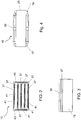
- the band body 15 is shown in a single representation.
- the band body 15 comprises a profile arrangement, which is composed of a plurality of profiles 41, 43.
- the profile arrangement comprises four profiles 41 extending in the transporting direction 13 of the piece goods and two profiles 43 extending transversely to the transport direction 13 of the piece goods.
- the profiles 41, 43 are in each case extruded profiles, in particular of aluminum.
- the weighing belt 11 has a cover plate 35 (cf. Fig. 1 ), in particular of metal, which is arranged between the upper side of the belt body 15 and the upper run of the conveyor belt 25, so that the upper strand of the conveyor belt 25 rests on the cover plate 35.
- the cover plate 35 extends in the transport direction 13 over the entire length of the belt body 15 and protrudes on both sides under the upper strand of the conveyor belt 25.
- the cover plate 35 is glued by means of a double-sided elastic adhesive tape 37 on the upper side of the belt body 15 (see. FIGS. 2 and 3 ).
- the adhesive tape 37 comprises a plurality of adhesive tape strips, which are each glued to one of the profiles 41, 43. Each adhesive tape strip 37 extends over at least 80% of the length of the respective profile 41, 43. Overall, the adhesive tape 37 extends over a length of at least 80% of the total length of the profiles 41, 43 together.
- the cover plate 35 is thus glued flat on the bench body 15.
- the width of the adhesive tape 37 or of the adhesive tape strips is smaller than the width or equal to the width of the respective profile 41, 43.
- the double-sided adhesive tape 37 consists of a uniform material, for example a closed-cell acrylate adhesive. Compared to a foam adhesive tape with a foam carrier, on which only a thin adhesive film is present on the top and bottom, higher shear forces can be absorbed by the adhesive tape 37 from a uniform material, without the adhesive tape 37 tearing or peeling off.
- a strut 39 is mounted, which extends transversely, in particular perpendicular to the transport direction 13 across the width of the belt body 15 (see. Fig. 4 ).
- the transverse strut 39 can also be fastened by means of a double-sided adhesive tape, as described above, or for example by means of screwing on the underside of the band body 15.
Landscapes
- Physics & Mathematics (AREA)
- General Physics & Mathematics (AREA)
- Engineering & Computer Science (AREA)
- Mechanical Engineering (AREA)
- Structure Of Belt Conveyors (AREA)
- Belt Conveyors (AREA)
Abstract
Description
- Die vorliegende Erfindung betrifft ein Förderband zum Transport von Stückgut, insbesondere Wägegut, insbesondere für eine Förderbandwaage zum Transport und zum Wiegen von Stückgut, insbesondere Wägegut, das einen Bandkörper mit einer Oberseite, einer Unterseite und einer sich in Transportrichtung des Stückguts erstreckenden Länge und ein im Betrieb des Förderbands um den Bandkörper umlaufendes Transportband umfasst.
- Bei bloßen Förderzwecken werden in der Regel keine besonderen Anforderungen an die Ebenheit der Oberseite der Bandkörpers gestellt, auf der das Obertrum des Transportbands, das das Stückgut transportiert, aufliegt und die als Gleitfläche für das Obertrum des Transportbands dient. Das Förderband kann jedoch auch Teil einer Förderbandwaage sein, bei der das Förderband auf einer Waageneinheit mit zumindest einer Wägezelle angeordnet ist, um das Gewicht eines jeweiligen Stückguts zu kontrollieren oder zu bestimmen. In diesem Fall kann ein an seiner Oberseite unebener Bandkörper dazu führen, dass im Betrieb des Förderbandwaage, d.h. wenn sich das Obertrum des Transportbands, insbesondere mit darauf befindlichem Wägegut, über die Oberseite des Bandkörpers hinwegbewegt, Schwingungen und damit zusätzliche vertikale Kräfte auf die Waageneinheit wirken, wodurch die Messergebnisse der Wiegungen verfälscht werden.
- Um derart verfälschte Messungen zu verhindern, ist es aus dem Dokument
DE 196 18 506 C2 bekannt, als Bandkörper eine Auflageplatte zu verwenden. Konkret ist diese Auflageplatte als Verbundplatte ausgebildet, die aus einem Kern aus druckfestem Material wie Hartschaumstoff mit ebener Oberfläche und einer dünnen oberen und unteren Deckschicht besteht, die jeweils unter Verwendung eines Klebers mit dem Kern verklebt sind. In dem DokumentDE 10 2007 020 311 A1 wird die erforderliche Ebenheit durch einen Bandkörper in Form einer Trägerplatte mit umgebogenen Seitenwangen erreicht. Die Herstellung der aus dem Stand der Technik bekannten Bandkörper ist jedoch vergleichsweise aufwändig. - Der Erfindung liegt die Aufgabe zugrunde, ein Förderband der eingangs genannten Art bereitzustellen, welches auf einfache Weise herstellbar ist und bei Verwendung in Verbindung mit einer Förderbandwaage eine Gewichtsermittlung mit hoher Genauigkeit ermöglicht.
- Diese Aufgabe wird durch eine Vorrichtung mit den Merkmalen des unabhängigen Anspruchs 1 gelöst, und insbesondere dadurch, dass eine Deckplatte vorgesehen ist, die mittels eines doppelseitigen Klebebands auf die Oberseite des Bandkörpers aufgeklebt ist und auf der das Obertrum des Transportbands aufliegt.
- Erfindungsgemäß ist also ein doppelseitiges Klebeband vorgesehen, das zwischen der Oberseite des Bandkörpers und der Deckplatte angeordnet ist, um die Deckplatte auf die Oberseite des Bandkörpers aufzukleben.
- Die Deckplatte, insbesondere Metallplatte, ermöglicht eine ebene Auflage- und Gleitfläche für das Transportband. Die insbesondere ebene Deckplatte mittels eines doppelseitigen Klebebands auf den Bandkörper aufzukleben, ist in der Herstellung deutlich einfacher als eine dünne Deckschicht mittels eines flüssigen Klebers auf einen Kern aus druckfestem Material aufzukleben, insbesondere deshalb, da kein zeitaufwändiger Trocknungsprozess erforderlich ist. Auch auf ein aufwändiges Umbiegen von Seitenwangen an einer Trägerplatte, bei dem sehr achtsam vorgegangen werden muss, um zu verhindern, dass die Ebenheit der Trägerplatte bei dem Umformvorgang leidet, kann verzichtet werden.
- Das erfindungsgemäße Förderband ist insbesondere dazu vorgesehen, in einer Förderbandwaage, insbesondere einem Checkweigher oder einem Preisauszeichner, eingesetzt zu werden. Die Förderbandwaage kann ein Zuführband, ein Wägeband und ein Abführband umfassen. Bevorzugt kommt das erfindungsgemäße Förderband dabei zumindest als Wägeband zum Einsatz. Es kann jedoch zusätzlich oder alternativ auch als Zuführband und/oder als Abführband zum Einsatz kommen.
- Bevorzugt umfasst das Förderband wenigstens eine Transportrolle, insbesondere zwei Transportrollen, die in Transportrichtung vor und hinter dem Bandkörper angeordnet sind, wobei dann das Transportband im Betrieb des Förderbands um den Bandkörper und die wenigstens eine Transportrolle, insbesondere die zwei Transportrollen, umläuft. Üblicherweise wird die hinter dem Bandkörper angeordnete Transportrolle angetrieben.
- Vorzugsweise besteht das Klebeband aus einem einheitlichen Material, d.h. das Klebeband besteht durch und durch aus Klebstoff. Ein Schaumstoff-Klebeband hingegen besteht aus einem Schaumträger, auf dem lediglich auf der Oberseite und/oder der Unterseite ein dünner Klebestofffilm vorhanden ist. Wirken auf ein Schaumstoff-Klebeband Scherkräfte, wird oft der Schaumstoffkern in Mitleidenschaft gezogen und reißt gegebenenfalls. Das Klebeband aus einem einheitlichen Material hingegen besteht nur aus Klebematerial, d.h. es besitzt keinen Kern aus Schaumstoff. Die Kraft, die ein derartiges Klebeband aushält, entspricht somit der Verbindungskraft des Klebstoffs. Wirken Scherkräfte, wird das Klebeband weniger schnell in Mitleidenschaft gezogen. Beispielsweise kann das insbesondere elastische Klebeband aus einem geschlossenzelligen Acrylatklebstoff bestehen.
- Vorzugsweise erstreckt sich die Deckplatte über zumindest im Wesentlichen die gesamte Länge des Bandkörpers, und/oder die Deckplatte kann in Transportrichtung des Förderbands ein- oder beidseitig unter dem Obertrum des Transportbands hervorstehen. Hierdurch kann gewährleistet werden, dass das Obertrum des Transportbands ganzflächig auf einer möglichst ebenen Oberfläche, insbesondere gleitend, aufliegt.
- Die Deckplatte ist bevorzugt aus einem Metall, insbesondere einer metallischen Legierung, insbesondere Stahl, gefertigt. Stahl ist besonders stabil. Der Bandkörper ist bevorzugt aus einem Metall, insbesondere Aluminium, gefertigt. Aluminium ist besonders leicht.
- Insgesamt kann bei Verwendung einer Deckplatte aus Stahl und eines Bandkörpers aus Aluminium eine hohe Stabilität bei gleichzeitig reduziertem Gewicht erreicht werden. Bei Verwendung des Förderband als Wägeband stellt das Förderband eine Vorlast für die Waageneinheit dar, d.h. die mindestens eine Wägezelle wiegt bei einem Wiegevorgang nicht nur das eigentliche Wägegut, sondern die zumindest eine Wägezelle wiegt zusätzlich auch immer das Förderband mit. Ist das Förderband leichter, ist das zu wiegende Gesamtgewicht aus Förderband und Wägegut geringer. Dies ist von Vorteil, da eine geringere Vorlast die Genauigkeit des Wägeprozesses erhöht. Aus diesem Grund ist es auch vorteilhaft, wenn, alternativ oder zusätzlich, die vorgenannte wenigstens eine Transportrolle, insbesondere die vorgenannten zwei Transportrollen jeweils, aus einem faserverstärktem Kunststoff gefertigt ist bzw. sind.
- Bei Verwendung einer Deckplatte aus Stahl und eines Bandkörpers aus Aluminium kann jedoch das Problem entstehen, dass ein Bimetall-Effekt auftritt, da die beiden unterschiedlichen Materialien bei Temperaturschwankungen verschiedenen Längenänderungen unterliegen. Dies betrifft insbesondere auch den Fall, dass sich die Temperatur bei der Herstellung des Bandkörpers von der Temperatur beim Betrieb des Bandkörpers unterscheidet. Hierdurch wird eine starre Verbindung, zum Beispiel durch Schrauben oder Nieten, oder bei Verwendung eines harten Klebers, jedoch belastet. Dies kann zu Verbiegungen des Bandkörpers und Unebenheiten führen. Durch die Verwendung eines Klebebands können derartige Probleme vermieden werden. Grundsätzlich wäre es auch denkbar, einen elastischen 2-Komponenten-Kleber zu verwenden, um die vorstehend erläuterten Probleme zu vermeiden. Ein derartiger Kleber müsste jedoch nass aufgebracht werden, und dann anschließend in einem Trocknungsprozess verfestigt werden. Ferner wären in diesem Fall Abstandshalter in Form von Kugeln, Drähten, Plättchen oder dergleichen erforderlich, um eine ausreichend dicke Klebeschicht gewährleisten zu können.
- An der Unterseite des Bandkörpers kann eine weitere Deckplatte oder eine Querstrebe angebracht sein, insbesondere mittels Anschrauben oder Kleben, insbesondere mittels eines doppelseitigen Klebebands, wie es vorstehend im Zusammenhang mit der Deckplatte, die auf die Oberseite des Bandkörpers aufgeklebt ist, erläutert ist. Die weitere Deckplatte bzw. die Querstrebe kann zur Stabilisierung des Rundlaufs des Förderbands beitragen.
- Bevorzugt besitzt die Deckplatte, insbesondere Metallplatte, eine Dicke von wenigstens 1 mm und/oder höchstens 3 mm, besonders bevorzugt im Bereich von 1,5 bis 2 mm.
- Gemäß einer Ausführungsform der Erfindung umfasst der Bandkörper eine aus mehreren Profilen, insbesondere Strangpressprofilen, insbesondere aus Aluminium, zusammengesetzte Profilanordnung. Bevorzugt ist das Klebeband dann auf den Profilen angebracht, insbesondere aufgeklebt. Insbesondere umfasst die Profilanordnung wenigstens zwei sich in Transportrichtung des Stückguts erstreckende Profile und wenigstens zwei sich quer, insbesondere senkrecht, zur Transportrichtung des Stückguts erstreckende Profile. Durch die Ausbildung des Bandkörpers als Profilanordnung kann das Gewicht des Bandkörpers reduziert werden.
- Bevorzugt umfasst das Klebeband mehrere Klebebandstreifen und die Gesamtlänge der Klebebandstreifen zusammen beträgt wenigstens 140% der Länge des Bandkörpers, insbesondere wenigstens 180% der Länge des Bandkörpers, insbesondere wenigstens 200% der Länge des Bandkörpers. Beispielsweise kann das Klebeband wenigstens zwei Klebebandstreifen umfassen, die an den beiden Längsseiten des Bandkörpers angebracht sind und die sich jeweils über wenigstens 70% der Länge des Bandkörpers, insbesondere über zumindest im Wesentlichen die gesamte Länge des Bandkörpers, erstrecken. Bevorzugt ist das Klebeband auf mehreren sich in Transportrichtung des Stückguts erstreckenden Profilen und/oder auf mehreren sich quer zur Transportrichtung des Stückguts erstreckenden Profilen angebracht. Bevorzugt erstreckt sich das Klebeband über eine Länge von wenigstens 40%, insbesondere wenigstens 60%, insbesondere wenigstens 80%, insbesondere zumindest im Wesentlichen 100%, der Gesamtlänge der Profile zusammen. Bevorzugt ist die Deckplatte flächig auf den Bandkörper, insbesondere die vorgenannte Profilanordnung, aufgeklebt.
- Die Erfindung betrifft ferner eine Förderbandwaage mit einer Waageneinheit mit mindestens einer Wägezelle und einem auf die Waageneinheit aufgesetzten Förderband gemäß der vorstehenden Beschreibung.
- Darüber hinaus betrifft die Erfindung ein Verfahren zur Herstellung eines Förderbands zum Transport von Stückgut, insbesondere für eine Förderbandwaage, das einen Bandkörper mit einer Oberseite, einer Unterseite und einer sich in Transportrichtung des Stückguts erstreckenden Länge und ein im Betrieb des Förderbands um den Bandkörper umlaufendes Transportband umfasst, bei dem mittels eines doppelseitigen Klebebands eine Deckplatte, auf der das Obertrum des Transportbands aufliegt, auf die Oberseite des Bandkörpers aufgeklebt wird. Bevorzugt werden anschließend der Bandkörper und die Deckplatte miteinander verpresst. Das Aufkleben der Deckplatte auf die Oberseite des Bandkörpers mittels des doppelseitigen Klebebands kann derart erfolgen, dass zuerst das doppelseitige Klebeband auf die Oberseite des Bandkörpers aufgebracht wird und danach die Deckplatte auf das doppelseitige Klebeband aufgebracht wird.
- Weiterbildungen des erfindungsgemäßen Verfahrens ergeben sich in analoger Weise aus den Weiterbildungen des erfindungsgemäßen Förderbands.
- Weitere vorteilhafte Ausgestaltungen der Erfindung sind in den Unteransprüchen, der Figurenbeschreibung und der Zeichnung beschrieben.
- Die Erfindung wird im Folgenden beispielhaft unter Bezugnahme auf die Zeichnung beschrieben. Es zeigen, jeweils in schematischer Darstellung,
- Fig. 1
- ein erfindungsgemäßes Förderband mit einem Bandkörper und einer Deckplatte in einer perspektivischen Ansicht,
- Fig. 2
- den Bandkörper aus
Fig. 1 in einer vereinfachten Ansicht von oben, - Fig. 3
- einen Ausschnitt des Bandkörpers und der Deckplatte aus
Fig. 1 in einer vereinfachten Schnittdarstellung, und - Fig. 4
- das Förderband aus
Fig. 1 in einer vereinfachten Ansicht von unten. - Das in
Fig. 1 gezeigte Förderband ist Teil einer Förderbandwaage, beispielsweise eines Checkweighers oder eines Preisauszeichners, die auf eine Waageneinheit mit mindestens einer Wägezelle, insbesondere bis zu vier Wägezellen, der Förderbandwaage aufgesetzt ist. Bei dem gezeigten Förderband handelt es sich dann um ein Wägeband 11. Das Wägeband 11 ist üblicherweise zwischen ein Zuführband und ein Abführband geschaltet, die in einer besonderen Ausführungsform ebenfalls die erfindungsgemäßen Merkmale des Wägebands 11 aufweisen können. Durch das Wägeband 11, insbesondere in Verbindung mit dem Zuführband und dem Abführband, kann Stückgut bzw. Wägegut über die Waageneinheit transportiert werden, um das Gewicht des jeweiligen Stückguts zu bestimmen. Die Gewichtsbestimmung erfolgt in der Regel während des Weitertransports des jeweiligen Stückguts. Grundsätzlich kann zur Gewichtsbestimmung der Transportvorgang jedoch auch angehalten werden. - Das Wägeband 11, das das Stückgut in einer Transportrichtung 13 transportiert, umfasst einen Bandkörper 15, insbesondere aus Aluminium, der zwischen einer ersten Transportrolle 17, die als Antriebsrolle ausgebildet ist, und einer zweiten Transportrolle 19, die als Mitlaufrolle ausgebildet ist, angeordnet ist. Die erste Transportrolle 17 und die zweite Transportrolle 19 sind in
Fig. 1 größtenteils durch weitere Bestandteile des Wägebands 11, auf die nachstehend noch näher eingegangen wird, verdeckt. Die beiden Transportrollen 17, 19 sind jeweils in zwei Halterungen 29 drehbar gelagert, die zu beiden Seiten des Bandkörpers 15 in der Transportrichtung 13 bzw. entgegen der Transportrichtung 13 von dem Bandkörper 15 abstehen. Die erste Transportrolle 17 wird über ein Riemengetriebe 21 von einem Elektromotor 23 angetrieben, der über eine Halteeinrichtung 27 an dem Bandkörper 15 fest angebracht ist. - Darüber hinaus umfasst das Wägeband 11 ein als Endlosgurt ausgebildetes Transportband 25, das im Betrieb des Wägebands 11 um den Bandkörper 15 und die beiden Transportrollen 17, 19 umläuft. Ferner umfasst das Wägeband 11 vier Abdeckbleche 31, die links und rechts der beiden Transportrollen 17, 19 angeordnet sind, wobei der Einfachheit halber lediglich die beiden in
Fig. 1 vorderen Abdeckbleche 31 mit einem Bezugszeichen versehen sind. Darüber hinaus ist ein- und auslaufseitig jeweils eine an dem Bandkörper 15 angebrachte Schutzleiste 33 für das Transportband 25 vorgesehen, über die das Wägeband 11 und ein zumindest auslaufseitig entsprechend ausgebildetes Zuführband und ein zumindest einlaufseitig entsprechend ausgebildetes Abführband Stoß-auf-Stoß aneinandergereiht werden können. - In
Fig. 2 ist der Bandkörper 15 in einer Einzeldarstellung gezeigt. Wie sich aus derFig. 2 ergibt, umfasst der Bandkörper 15 eine Profilanordnung, die aus mehreren Profilen 41, 43 zusammengesetzt ist. In dem gezeigten Beispiel umfasst die Profilanordnung vier sich in Transportrichtung 13 des Stückguts erstreckende Profile 41 und zwei sich quer zur Transportrichtung 13 des Stückguts erstreckende Profile 43. Bei den Profilen 41, 43 handelt es sich jeweils um Strangpressprofile, insbesondere aus Aluminium. - Um das Gewicht der über die Waageneinheit transportierten Stückgüter mit möglichst hoher Genauigkeit bestimmen zu können, ist es erforderlich, dass das Obertrum des Transportbands 25 auf einer möglichst ebenen Oberfläche aufliegt bzw. über eine möglichst ebene Oberfläche hinweggleiten kann. Um dies zu erreichen, weist das Wägeband 11 eine Deckplatte 35 auf (vgl.
Fig. 1 ), insbesondere aus Metall, die zwischen der Oberseite des Bandkörpers 15 und dem Obertrum des Transportbands 25 angeordnet ist, so dass das Obertrum des Transportbands 25 auf der Deckplatte 35 aufliegt. Die Deckplatte 35 erstreckt sich dabei in Transportrichtung 13 über die gesamte Länge des Bandkörpers 15 und steht beidseitig unter dem Obertrum des Transportbands 25 hervor. - Die Deckplatte 35 ist mittels eines doppelseitigen elastischen Klebebands 37 auf die Oberseite des Bandkörpers 15 aufgeklebt (vgl.
Fig. 2 und 3 ). Das Klebeband 37 umfasst mehrere Klebebandstreifen, die jeweils auf eines der Profile 41, 43 aufgeklebt sind. Jeder Klebebandstreifen 37 erstreckt sich über wenigstens 80% der Länge des jeweiligen Profils 41, 43. Insgesamt erstreckt sich das Klebeband 37 damit über eine Länge von wenigstens 80% der Gesamtlänge der Profile 41, 43 zusammen. Die Deckplatte 35 ist damit flächig auf den Bankkörper 15 aufgeklebt. Die Breite des Klebebands 37 bzw. der Klebebandstreifen ist dabei kleiner als die Breite oder gleich der Breite des jeweiligen Profils 41, 43. - Das doppelseitige Klebeband 37 besteht aus einem einheitlichen Material, beispielsweise aus einem geschlossenzelligen Acrylatklebstoff. Gegenüber einem Schaumstoff-Klebeband mit einem Schaumträger, auf dem lediglich auf der Oberseite und der Unterseite ein dünner Klebestofffilm vorhanden ist, können durch das Klebeband 37 aus einem einheitlichen Material höhere Scherkräfte aufgenommen werden, ohne dass das Klebeband 37 reißt oder sich ablöst.
- Darüber hinaus ist an der Unterseite des Bandkörpers 15, zumindest im Wesentlichen mittig, eine Strebe 39 angebracht, die sich quer, insbesondere senkrecht zur Transportrichtung 13 über die Breite des Bandkörpers 15 erstreckt (vgl. insb.
Fig. 4 ). Die Querstrebe 39 kann ebenfalls mittels eines doppelseitigen Klebebands, wie es vorstehend beschrieben ist, oder beispielsweise mittels Anschrauben an der Unterseite des Bandkörpers 15 befestigt werden. Durch die Querstrebe 39 kann ein ruhiger Lauf des Untertrums des Transportbands 25 unterstützt werden. - Durch das erfindungsgemäße Förderband mit der mittels des doppelseitigen Klebebands aufgeklebten Deckplatte kann auf einfache Weise eine ebene Unterlage für das Obertrum des Transportbands realisiert werden, wodurch bei einer Gewichtsbestimmung eine hohe Genauigkeit ermöglicht wird.
-
- 11
- Wägeband
- 13
- Transportrichtung
- 15
- Bandkörper
- 17
- Transportrolle
- 19
- Transportrolle
- 21
- Riemengetriebe
- 23
- Elektromotor
- 25
- Transportband
- 27
- Halteeinrichtung
- 29
- Halterung
- 31
- Abdeckleiste
- 33
- Schutzleiste
- 35
- Deckplatte
- 37
- Klebeband
- 39
- Querstrebe
- 41
- Profil
- 43
- Profil
Claims (12)
- Förderband zum Transport von Stückgut, insbesondere für eine Förderbandwaage, das einen Bandkörper (15) mit einer Oberseite, einer Unterseite und einer sich in Transportrichtung (13) des Stückguts erstreckenden Länge und ein im Betrieb des Förderbands (11) um den Bandkörper (15) umlaufendes Transportband (25) umfasst,
dadurch gekennzeichnet, dass
eine Deckplatte (35) vorgesehen ist, die mittels eines doppelseitigen Klebebands (37) auf die Oberseite des Bandkörpers (15) aufgeklebt ist und auf der das Obertrum des Transportbands (25) aufliegt. - Förderband nach Anspruch 1,
dadurch gekennzeichnet, dass
das Klebeband (37) aus einem einheitlichen Material besteht. - Förderband nach Anspruch 1 oder 2,
dadurch gekennzeichnet, dass
das Klebeband (37) aus einem geschlossenzelligen Acrylatklebstoff besteht. - Förderband nach zumindest einem der vorstehenden Ansprüche,
dadurch gekennzeichnet, dass
sich die Deckplatte (35) über die gesamte Länge des Bandkörpers (15) erstreckt. - Förderband nach zumindest einem der vorstehenden Ansprüche,
dadurch gekennzeichnet, dass
die Deckplatte (35) in Transportrichtung (13) des Förderbands (11) ein- oder beidseitig unter dem Obertrum des Transportbands (25) hervorsteht. - Förderband nach zumindest einem der vorstehenden Ansprüche,
dadurch gekennzeichnet, dass
die Deckplatte (35) aus einem Metall, insbesondere einer metallischen Legierung, insbesondere Stahl, gefertigt ist. - Förderband nach zumindest einem der vorstehenden Ansprüche,
dadurch gekennzeichnet, dass
der Bandkörper (15) aus einem Metall, insbesondere Aluminium, gefertigt ist. - Förderband nach zumindest einem der vorstehenden Ansprüche,
dadurch gekennzeichnet, dass
an der Unterseite des Bandkörpers (15) eine weitere Deckplatte oder eine Querstrebe (39) angebracht ist, insbesondere mittels Anschrauben oder Kleben. - Förderband nach zumindest einem der vorstehenden Ansprüche,
dadurch gekennzeichnet, dass
der Bandkörper (15) eine aus mehreren Profilen (41, 43) zusammengesetzte Profilanordnung umfasst, wobei das Klebeband (37) auf den Profilen (41, 43) angebracht ist. - Förderband nach zumindest einem der vorstehenden Ansprüche,
dadurch gekennzeichnet, dass
das Klebeband (37) mehrere Klebebandstreifen umfasst, und die Gesamtlänge der Klebebandstreifen zusammen wenigstens 140% der Länge des Bandkörpers (15) beträgt und /oder sich das Klebeband (37) über eine Länge von wenigstens 40% der Gesamtlänge der Profile (41, 43) zusammen erstreckt. - Förderbandwaage mit einer Waageneinheit mit zumindest einer Wägezelle und einem auf die Waageneinheit aufgesetzten Förderband (11) gemäß einem der vorstehenden Ansprüche.
- Verfahren zur Herstellung eines Förderbands (11) zum Transport von Stückgut, insbesondere für eine Förderbandwaage, das einen Bandkörper (15) mit einer Oberseite, einer Unterseite und einer sich in Transportrichtung (1) des Stückguts erstreckenden Länge und ein im Betrieb des Förderbands (11) um den Bandkörper (15) umlaufendes Transportband (25) umfasst, bei dem mittels eines doppelseitigen Klebebands (37) eine Deckplatte (35), auf der das Obertrum des Transportbands (25) aufliegt, auf die Oberseite des Bandkörpers (15) aufgeklebt wird.
Applications Claiming Priority (1)
| Application Number | Priority Date | Filing Date | Title |
|---|---|---|---|
| DE102016125774.5A DE102016125774A1 (de) | 2016-12-28 | 2016-12-28 | Förderbandwaage mit Förderband sowie Förderband |
Publications (3)
| Publication Number | Publication Date |
|---|---|
| EP3343188A2 true EP3343188A2 (de) | 2018-07-04 |
| EP3343188A3 EP3343188A3 (de) | 2018-10-03 |
| EP3343188B1 EP3343188B1 (de) | 2021-08-18 |
Family
ID=60201386
Family Applications (1)
| Application Number | Title | Priority Date | Filing Date |
|---|---|---|---|
| EP17199157.3A Active EP3343188B1 (de) | 2016-12-28 | 2017-10-30 | Förderbandwaage mit förderband sowie förderband |
Country Status (2)
| Country | Link |
|---|---|
| EP (1) | EP3343188B1 (de) |
| DE (1) | DE102016125774A1 (de) |
Cited By (1)
| Publication number | Priority date | Publication date | Assignee | Title |
|---|---|---|---|---|
| CN112978215A (zh) * | 2020-02-11 | 2021-06-18 | 伟博泰有限公司 | 防夹装置 |
Families Citing this family (1)
| Publication number | Priority date | Publication date | Assignee | Title |
|---|---|---|---|---|
| CN111504430A (zh) * | 2020-05-18 | 2020-08-07 | 南通春光自控设备工程有限公司 | 一种皮带秤 |
Family Cites Families (4)
| Publication number | Priority date | Publication date | Assignee | Title |
|---|---|---|---|---|
| CH195807A (de) * | 1936-12-22 | 1938-02-15 | Laurie Ing William | Förderanlage. |
| US4927007A (en) * | 1989-09-27 | 1990-05-22 | The B. F. Goodrich Company | Conveyor support |
| DE19618506C2 (de) | 1996-05-08 | 1998-09-17 | Wipotec Wiege & Positioniersys | Förderband, insbesondere für einen Wägebandförderer |
| DE102007020311A1 (de) | 2007-04-17 | 2008-10-30 | Bizerba Gmbh & Co. Kg | Wäge-Fördervorrichtung |
-
2016
- 2016-12-28 DE DE102016125774.5A patent/DE102016125774A1/de not_active Withdrawn
-
2017
- 2017-10-30 EP EP17199157.3A patent/EP3343188B1/de active Active
Cited By (3)
| Publication number | Priority date | Publication date | Assignee | Title |
|---|---|---|---|---|
| CN112978215A (zh) * | 2020-02-11 | 2021-06-18 | 伟博泰有限公司 | 防夹装置 |
| EP3865432A1 (de) * | 2020-02-11 | 2021-08-18 | WIPOTEC GmbH | Eingreifschutz |
| US11440738B2 (en) | 2020-02-11 | 2022-09-13 | Wipotec Gmbh | Contact protection apparatus for covering a pinching gap adjacent to a roller |
Also Published As
| Publication number | Publication date |
|---|---|
| EP3343188B1 (de) | 2021-08-18 |
| EP3343188A3 (de) | 2018-10-03 |
| DE102016125774A1 (de) | 2018-06-28 |
Similar Documents
| Publication | Publication Date | Title |
|---|---|---|
| EP1816075B1 (de) | Verpackungsmachine, insbesondere Rollen- oder Tiefziehmaschine, Schalenversiegelungsmaschine oder dergleichen | |
| DE102013203457B4 (de) | Gestell einer Wäge-Fördervorrichtung | |
| EP3243694B1 (de) | Vorrichtung zur anbringung einer sitzanordnung in einem fahrzeug und fahrzeug | |
| EP3978361B1 (de) | Verfahren zur herstellung eines bodenmoduls | |
| EP2396113B1 (de) | Diagnostisches testband für flüssigproben | |
| EP3343188B1 (de) | Förderbandwaage mit förderband sowie förderband | |
| WO2014131567A1 (de) | Wäge-fördervorrichtung | |
| DE102013204244B4 (de) | Hochleistungsbandanlage | |
| DE202018006182U1 (de) | Stützelement für eine Transportplattform | |
| EP4166481A1 (de) | Umlenkelement | |
| DE102017110995A1 (de) | Vorpresse und System zum kontinuierlichen Herstellen von Werkstoffplatten, Verfahren zum Einbringen oder Entnehmen des Pressenbandes und Transportvorrichtung zum Aufnehmen des Pressenbandes | |
| DE19618506C2 (de) | Förderband, insbesondere für einen Wägebandförderer | |
| EP4332024B1 (de) | Förderbandwaage mit förderband sowie förderbandkörper | |
| DE102012016174A1 (de) | Schaltschrankkran, Schaltschrank, und Verfahren zur Verwendung bei einer Montage eines Geräts in einem Schaltschrank | |
| DE102004063704B4 (de) | Teleskop-Gurtförderer | |
| EP3021093B1 (de) | Bandwaage | |
| DE1954426U (de) | Ausgabevorrichtung fuer blattfoermiges material, insbesondere emulsionsbeschichtete blaetter fuer photographische zwecke. | |
| DE1952429C3 (de) | Fordervorrichtung | |
| EP3615898B1 (de) | Kalibrierung einer förder- und dosiervorrichtung | |
| DE29813546U1 (de) | Förderbandwaage mit seitlichen Produktführungsbändern | |
| DE102022112578B4 (de) | Kurvenfördermodul für eine Transporteinrichtung zum Transportieren von Stückgütern, insbesondere von Paketen, entlang eines Transportweges | |
| DE69903649T2 (de) | Werbeplakat und vorrichtung zur anzeige von werbeträgern | |
| EP1927557A2 (de) | Lagervorrichtung | |
| DE2842984C2 (de) | Friktionsrollenbahn mit seitlichen Profilschienen | |
| DE2331339A1 (de) | Vorrichtung zum kontinuierlichen herstellen von kunststoffplatten od. dgl |
Legal Events
| Date | Code | Title | Description |
|---|---|---|---|
| PUAI | Public reference made under article 153(3) epc to a published international application that has entered the european phase |
Free format text: ORIGINAL CODE: 0009012 |
|
| STAA | Information on the status of an ep patent application or granted ep patent |
Free format text: STATUS: THE APPLICATION HAS BEEN PUBLISHED |
|
| AK | Designated contracting states |
Kind code of ref document: A2 Designated state(s): AL AT BE BG CH CY CZ DE DK EE ES FI FR GB GR HR HU IE IS IT LI LT LU LV MC MK MT NL NO PL PT RO RS SE SI SK SM TR |
|
| AX | Request for extension of the european patent |
Extension state: BA ME |
|
| PUAL | Search report despatched |
Free format text: ORIGINAL CODE: 0009013 |
|
| AK | Designated contracting states |
Kind code of ref document: A3 Designated state(s): AL AT BE BG CH CY CZ DE DK EE ES FI FR GB GR HR HU IE IS IT LI LT LU LV MC MK MT NL NO PL PT RO RS SE SI SK SM TR |
|
| AX | Request for extension of the european patent |
Extension state: BA ME |
|
| RIC1 | Information provided on ipc code assigned before grant |
Ipc: B65G 15/62 20060101ALI20180827BHEP Ipc: G01G 11/00 20060101AFI20180827BHEP |
|
| STAA | Information on the status of an ep patent application or granted ep patent |
Free format text: STATUS: REQUEST FOR EXAMINATION WAS MADE |
|
| 17P | Request for examination filed |
Effective date: 20190326 |
|
| RBV | Designated contracting states (corrected) |
Designated state(s): AL AT BE BG CH CY CZ DE DK EE ES FI FR GB GR HR HU IE IS IT LI LT LU LV MC MK MT NL NO PL PT RO RS SE SI SK SM TR |
|
| STAA | Information on the status of an ep patent application or granted ep patent |
Free format text: STATUS: EXAMINATION IS IN PROGRESS |
|
| 17Q | First examination report despatched |
Effective date: 20200603 |
|
| GRAP | Despatch of communication of intention to grant a patent |
Free format text: ORIGINAL CODE: EPIDOSNIGR1 |
|
| STAA | Information on the status of an ep patent application or granted ep patent |
Free format text: STATUS: GRANT OF PATENT IS INTENDED |
|
| INTG | Intention to grant announced |
Effective date: 20210223 |
|
| GRAS | Grant fee paid |
Free format text: ORIGINAL CODE: EPIDOSNIGR3 |
|
| GRAA | (expected) grant |
Free format text: ORIGINAL CODE: 0009210 |
|
| STAA | Information on the status of an ep patent application or granted ep patent |
Free format text: STATUS: THE PATENT HAS BEEN GRANTED |
|
| AK | Designated contracting states |
Kind code of ref document: B1 Designated state(s): AL AT BE BG CH CY CZ DE DK EE ES FI FR GB GR HR HU IE IS IT LI LT LU LV MC MK MT NL NO PL PT RO RS SE SI SK SM TR |
|
| REG | Reference to a national code |
Ref country code: GB Ref legal event code: FG4D Free format text: NOT ENGLISH |
|
| REG | Reference to a national code |
Ref country code: CH Ref legal event code: EP |
|
| REG | Reference to a national code |
Ref country code: DE Ref legal event code: R096 Ref document number: 502017011212 Country of ref document: DE |
|
| REG | Reference to a national code |
Ref country code: IE Ref legal event code: FG4D Free format text: LANGUAGE OF EP DOCUMENT: GERMAN Ref country code: AT Ref legal event code: REF Ref document number: 1422045 Country of ref document: AT Kind code of ref document: T Effective date: 20210915 |
|
| REG | Reference to a national code |
Ref country code: NL Ref legal event code: FP |
|
| REG | Reference to a national code |
Ref country code: LT Ref legal event code: MG9D |
|
| PG25 | Lapsed in a contracting state [announced via postgrant information from national office to epo] |
Ref country code: SE Free format text: LAPSE BECAUSE OF FAILURE TO SUBMIT A TRANSLATION OF THE DESCRIPTION OR TO PAY THE FEE WITHIN THE PRESCRIBED TIME-LIMIT Effective date: 20210818 Ref country code: RS Free format text: LAPSE BECAUSE OF FAILURE TO SUBMIT A TRANSLATION OF THE DESCRIPTION OR TO PAY THE FEE WITHIN THE PRESCRIBED TIME-LIMIT Effective date: 20210818 Ref country code: HR Free format text: LAPSE BECAUSE OF FAILURE TO SUBMIT A TRANSLATION OF THE DESCRIPTION OR TO PAY THE FEE WITHIN THE PRESCRIBED TIME-LIMIT Effective date: 20210818 Ref country code: BG Free format text: LAPSE BECAUSE OF FAILURE TO SUBMIT A TRANSLATION OF THE DESCRIPTION OR TO PAY THE FEE WITHIN THE PRESCRIBED TIME-LIMIT Effective date: 20211118 Ref country code: LT Free format text: LAPSE BECAUSE OF FAILURE TO SUBMIT A TRANSLATION OF THE DESCRIPTION OR TO PAY THE FEE WITHIN THE PRESCRIBED TIME-LIMIT Effective date: 20210818 Ref country code: NO Free format text: LAPSE BECAUSE OF FAILURE TO SUBMIT A TRANSLATION OF THE DESCRIPTION OR TO PAY THE FEE WITHIN THE PRESCRIBED TIME-LIMIT Effective date: 20211118 Ref country code: PT Free format text: LAPSE BECAUSE OF FAILURE TO SUBMIT A TRANSLATION OF THE DESCRIPTION OR TO PAY THE FEE WITHIN THE PRESCRIBED TIME-LIMIT Effective date: 20211220 Ref country code: ES Free format text: LAPSE BECAUSE OF FAILURE TO SUBMIT A TRANSLATION OF THE DESCRIPTION OR TO PAY THE FEE WITHIN THE PRESCRIBED TIME-LIMIT Effective date: 20210818 Ref country code: FI Free format text: LAPSE BECAUSE OF FAILURE TO SUBMIT A TRANSLATION OF THE DESCRIPTION OR TO PAY THE FEE WITHIN THE PRESCRIBED TIME-LIMIT Effective date: 20210818 |
|
| PG25 | Lapsed in a contracting state [announced via postgrant information from national office to epo] |
Ref country code: PL Free format text: LAPSE BECAUSE OF FAILURE TO SUBMIT A TRANSLATION OF THE DESCRIPTION OR TO PAY THE FEE WITHIN THE PRESCRIBED TIME-LIMIT Effective date: 20210818 Ref country code: LV Free format text: LAPSE BECAUSE OF FAILURE TO SUBMIT A TRANSLATION OF THE DESCRIPTION OR TO PAY THE FEE WITHIN THE PRESCRIBED TIME-LIMIT Effective date: 20210818 Ref country code: GR Free format text: LAPSE BECAUSE OF FAILURE TO SUBMIT A TRANSLATION OF THE DESCRIPTION OR TO PAY THE FEE WITHIN THE PRESCRIBED TIME-LIMIT Effective date: 20211119 |
|
| PG25 | Lapsed in a contracting state [announced via postgrant information from national office to epo] |
Ref country code: DK Free format text: LAPSE BECAUSE OF FAILURE TO SUBMIT A TRANSLATION OF THE DESCRIPTION OR TO PAY THE FEE WITHIN THE PRESCRIBED TIME-LIMIT Effective date: 20210818 |
|
| REG | Reference to a national code |
Ref country code: DE Ref legal event code: R097 Ref document number: 502017011212 Country of ref document: DE |
|
| PG25 | Lapsed in a contracting state [announced via postgrant information from national office to epo] |
Ref country code: SM Free format text: LAPSE BECAUSE OF FAILURE TO SUBMIT A TRANSLATION OF THE DESCRIPTION OR TO PAY THE FEE WITHIN THE PRESCRIBED TIME-LIMIT Effective date: 20210818 Ref country code: SK Free format text: LAPSE BECAUSE OF FAILURE TO SUBMIT A TRANSLATION OF THE DESCRIPTION OR TO PAY THE FEE WITHIN THE PRESCRIBED TIME-LIMIT Effective date: 20210818 Ref country code: RO Free format text: LAPSE BECAUSE OF FAILURE TO SUBMIT A TRANSLATION OF THE DESCRIPTION OR TO PAY THE FEE WITHIN THE PRESCRIBED TIME-LIMIT Effective date: 20210818 Ref country code: EE Free format text: LAPSE BECAUSE OF FAILURE TO SUBMIT A TRANSLATION OF THE DESCRIPTION OR TO PAY THE FEE WITHIN THE PRESCRIBED TIME-LIMIT Effective date: 20210818 Ref country code: CZ Free format text: LAPSE BECAUSE OF FAILURE TO SUBMIT A TRANSLATION OF THE DESCRIPTION OR TO PAY THE FEE WITHIN THE PRESCRIBED TIME-LIMIT Effective date: 20210818 Ref country code: AL Free format text: LAPSE BECAUSE OF FAILURE TO SUBMIT A TRANSLATION OF THE DESCRIPTION OR TO PAY THE FEE WITHIN THE PRESCRIBED TIME-LIMIT Effective date: 20210818 |
|
| REG | Reference to a national code |
Ref country code: CH Ref legal event code: PL |
|
| REG | Reference to a national code |
Ref country code: BE Ref legal event code: MM Effective date: 20211031 |
|
| PLBE | No opposition filed within time limit |
Free format text: ORIGINAL CODE: 0009261 |
|
| STAA | Information on the status of an ep patent application or granted ep patent |
Free format text: STATUS: NO OPPOSITION FILED WITHIN TIME LIMIT |
|
| PG25 | Lapsed in a contracting state [announced via postgrant information from national office to epo] |
Ref country code: MC Free format text: LAPSE BECAUSE OF FAILURE TO SUBMIT A TRANSLATION OF THE DESCRIPTION OR TO PAY THE FEE WITHIN THE PRESCRIBED TIME-LIMIT Effective date: 20210818 |
|
| 26N | No opposition filed |
Effective date: 20220519 |
|
| PG25 | Lapsed in a contracting state [announced via postgrant information from national office to epo] |
Ref country code: LU Free format text: LAPSE BECAUSE OF NON-PAYMENT OF DUE FEES Effective date: 20211030 Ref country code: IT Free format text: LAPSE BECAUSE OF FAILURE TO SUBMIT A TRANSLATION OF THE DESCRIPTION OR TO PAY THE FEE WITHIN THE PRESCRIBED TIME-LIMIT Effective date: 20210818 Ref country code: BE Free format text: LAPSE BECAUSE OF NON-PAYMENT OF DUE FEES Effective date: 20211031 |
|
| PG25 | Lapsed in a contracting state [announced via postgrant information from national office to epo] |
Ref country code: SI Free format text: LAPSE BECAUSE OF FAILURE TO SUBMIT A TRANSLATION OF THE DESCRIPTION OR TO PAY THE FEE WITHIN THE PRESCRIBED TIME-LIMIT Effective date: 20210818 Ref country code: LI Free format text: LAPSE BECAUSE OF NON-PAYMENT OF DUE FEES Effective date: 20211031 Ref country code: CH Free format text: LAPSE BECAUSE OF NON-PAYMENT OF DUE FEES Effective date: 20211031 |
|
| PG25 | Lapsed in a contracting state [announced via postgrant information from national office to epo] |
Ref country code: IE Free format text: LAPSE BECAUSE OF NON-PAYMENT OF DUE FEES Effective date: 20211030 |
|
| PG25 | Lapsed in a contracting state [announced via postgrant information from national office to epo] |
Ref country code: HU Free format text: LAPSE BECAUSE OF FAILURE TO SUBMIT A TRANSLATION OF THE DESCRIPTION OR TO PAY THE FEE WITHIN THE PRESCRIBED TIME-LIMIT; INVALID AB INITIO Effective date: 20171030 |
|
| PG25 | Lapsed in a contracting state [announced via postgrant information from national office to epo] |
Ref country code: CY Free format text: LAPSE BECAUSE OF FAILURE TO SUBMIT A TRANSLATION OF THE DESCRIPTION OR TO PAY THE FEE WITHIN THE PRESCRIBED TIME-LIMIT Effective date: 20210818 |
|
| PG25 | Lapsed in a contracting state [announced via postgrant information from national office to epo] |
Ref country code: MK Free format text: LAPSE BECAUSE OF FAILURE TO SUBMIT A TRANSLATION OF THE DESCRIPTION OR TO PAY THE FEE WITHIN THE PRESCRIBED TIME-LIMIT Effective date: 20210818 |
|
| PG25 | Lapsed in a contracting state [announced via postgrant information from national office to epo] |
Ref country code: MT Free format text: LAPSE BECAUSE OF FAILURE TO SUBMIT A TRANSLATION OF THE DESCRIPTION OR TO PAY THE FEE WITHIN THE PRESCRIBED TIME-LIMIT Effective date: 20210818 |
|
| PGFP | Annual fee paid to national office [announced via postgrant information from national office to epo] |
Ref country code: NL Payment date: 20251023 Year of fee payment: 9 |
|
| PG25 | Lapsed in a contracting state [announced via postgrant information from national office to epo] |
Ref country code: TR Free format text: LAPSE BECAUSE OF FAILURE TO SUBMIT A TRANSLATION OF THE DESCRIPTION OR TO PAY THE FEE WITHIN THE PRESCRIBED TIME-LIMIT Effective date: 20210818 |
|
| PGFP | Annual fee paid to national office [announced via postgrant information from national office to epo] |
Ref country code: DE Payment date: 20251020 Year of fee payment: 9 |
|
| PGFP | Annual fee paid to national office [announced via postgrant information from national office to epo] |
Ref country code: GB Payment date: 20251024 Year of fee payment: 9 |
|
| PGFP | Annual fee paid to national office [announced via postgrant information from national office to epo] |
Ref country code: AT Payment date: 20251021 Year of fee payment: 9 |
|
| PGFP | Annual fee paid to national office [announced via postgrant information from national office to epo] |
Ref country code: FR Payment date: 20251029 Year of fee payment: 9 |