EP3343082A1 - Flächentemperierungssystem - Google Patents
Flächentemperierungssystem Download PDFInfo
- Publication number
- EP3343082A1 EP3343082A1 EP17205351.4A EP17205351A EP3343082A1 EP 3343082 A1 EP3343082 A1 EP 3343082A1 EP 17205351 A EP17205351 A EP 17205351A EP 3343082 A1 EP3343082 A1 EP 3343082A1
- Authority
- EP
- European Patent Office
- Prior art keywords
- layer
- carrier film
- temperature control
- control system
- insulating mat
- Prior art date
- Legal status (The legal status is an assumption and is not a legal conclusion. Google has not performed a legal analysis and makes no representation as to the accuracy of the status listed.)
- Granted
Links
Images
Classifications
-
- F—MECHANICAL ENGINEERING; LIGHTING; HEATING; WEAPONS; BLASTING
- F16—ENGINEERING ELEMENTS AND UNITS; GENERAL MEASURES FOR PRODUCING AND MAINTAINING EFFECTIVE FUNCTIONING OF MACHINES OR INSTALLATIONS; THERMAL INSULATION IN GENERAL
- F16L—PIPES; JOINTS OR FITTINGS FOR PIPES; SUPPORTS FOR PIPES, CABLES OR PROTECTIVE TUBING; MEANS FOR THERMAL INSULATION IN GENERAL
- F16L3/00—Supports for pipes, cables or protective tubing, e.g. hangers, holders, clamps, cleats, clips, brackets
- F16L3/08—Supports for pipes, cables or protective tubing, e.g. hangers, holders, clamps, cleats, clips, brackets substantially surrounding the pipe, cable or protective tubing
-
- F—MECHANICAL ENGINEERING; LIGHTING; HEATING; WEAPONS; BLASTING
- F24—HEATING; RANGES; VENTILATING
- F24D—DOMESTIC- OR SPACE-HEATING SYSTEMS, e.g. CENTRAL HEATING SYSTEMS; DOMESTIC HOT-WATER SUPPLY SYSTEMS; ELEMENTS OR COMPONENTS THEREFOR
- F24D3/00—Hot-water central heating systems
- F24D3/12—Tube and panel arrangements for ceiling, wall, or underfloor heating
- F24D3/14—Tube and panel arrangements for ceiling, wall, or underfloor heating incorporated in a ceiling, wall or floor
- F24D3/141—Tube mountings specially adapted therefor
-
- F—MECHANICAL ENGINEERING; LIGHTING; HEATING; WEAPONS; BLASTING
- F24—HEATING; RANGES; VENTILATING
- F24D—DOMESTIC- OR SPACE-HEATING SYSTEMS, e.g. CENTRAL HEATING SYSTEMS; DOMESTIC HOT-WATER SUPPLY SYSTEMS; ELEMENTS OR COMPONENTS THEREFOR
- F24D3/00—Hot-water central heating systems
- F24D3/12—Tube and panel arrangements for ceiling, wall, or underfloor heating
- F24D3/14—Tube and panel arrangements for ceiling, wall, or underfloor heating incorporated in a ceiling, wall or floor
- F24D3/145—Convecting elements concealed in wall or floor
-
- Y—GENERAL TAGGING OF NEW TECHNOLOGICAL DEVELOPMENTS; GENERAL TAGGING OF CROSS-SECTIONAL TECHNOLOGIES SPANNING OVER SEVERAL SECTIONS OF THE IPC; TECHNICAL SUBJECTS COVERED BY FORMER USPC CROSS-REFERENCE ART COLLECTIONS [XRACs] AND DIGESTS
- Y02—TECHNOLOGIES OR APPLICATIONS FOR MITIGATION OR ADAPTATION AGAINST CLIMATE CHANGE
- Y02B—CLIMATE CHANGE MITIGATION TECHNOLOGIES RELATED TO BUILDINGS, e.g. HOUSING, HOUSE APPLIANCES OR RELATED END-USER APPLICATIONS
- Y02B30/00—Energy efficient heating, ventilation or air conditioning [HVAC]
Definitions
- the present invention relates to a surface temperature control system, the at least one flexible plastic pipe, the outside of which is at least partially encased by a first element of a Velcro connection; a carrier film, wherein on one side of the carrier film, a second element of the Velcro connection is arranged, so that the / the flexible (s) plastic tube (s) releasably to form the Velcro connection to the carrier film is / is fixable; and a dimensionally stable, flat carrier, which is formed as a heat and impact sound insulating mat with a plurality of stabilizing seams comprises.
- this describes DE 20 2010 009 133 U1 a surface temperature control system with a Velcro fibreboard of a dimensionally stable sheet carrier with a thickness between 2.5 mm and 7 mm, on which a fabric-reinforced film is applied, which forms a first element of a hook and a flexible tube, which at least partially with a second element of the hook and loop device is sheathed.
- the dimensionally stable, flat support is laid before the application of the flexible plastic pipe and pouring with screed on an additional required insulating layer.
- the DE 20 2015 100 914 U1 a dimensionally stable, flat carrier, which is formed as an insulating layer, wherein the one element of the hook and loop fastener supporting carrier film adhered to the insulating layer or sewn to the insulating layer, twisted or intertwined.
- the disadvantage of this is considered to be perforated by the attachment of the carrier film to the insulating layer by means of stitching, sewing, twisting or braiding the carrier film. Due to the mechanical stress on the construction site on the one hand and by the restoring forces of the flexible plastic pipes on the other hand, there is a risk that the holes caused by the seams in the carrier film are still increased.
- the function of the carrier film as a liquid-tight protective layer is impaired. For example, screed mixing water can penetrate into the insulation layer, cause moisture damage and negatively affect its function as heat and impact sound insulation. Due to their structure, fiber insulating materials are particularly endangered here.
- the present invention sets in, the object of which is to provide a surface temperature control system which overcomes the disadvantages of the prior art.
- the surface temperature control system according to the invention should be moisture-proof.
- the surface temperature control system according to the invention should have a simple structure and be easy to install.
- the risk of water penetration, in particular of screed mixing water, into the insulating material of the insulating layer can be eliminated by otherwise applying the carrier film to one side of the insulating mat, without the carrier film with the insulating mat sew, so for example by gluing or laminating.
- the sticking or lamination of the carrier film can take place over the entire surface, in strip form, at points or in a combination of the mentioned geometries.
- the carrier film is not perforated, so that no holes are present, which would allow penetration of water into the insulating material. Due to the carrier film, the insulating material of the insulation layer is protected from water, so that this his heat and impact sound insulation Properties are preserved.
- the insulation mat has a plurality of stabilizing seams, by which the insulation mat represents a compact composite which is suitable for use as a dimensionally stable, flat carrier of a surface tempering system.
- the present invention is to provide a surface temperature control system, the at least one flexible plastic tube whose outer side is at least partially covered by a first element of a Velcro connection; a carrier film, wherein on one side of the carrier film, a second element of the Velcro connection is arranged, so that the / the flexible (s) plastic tube (s) releasably to form the Velcro connection to the carrier film is / is fixable; and a dimensionally stable, flat carrier, which is designed as a heat and impact sound insulating mat with a plurality of stabilizing seams comprises, wherein the carrier film is fixed on one side of the heat and impact sound insulating mat without the stabilizing seams penetrate the carrier film.
- plastic pipe means a solid plastic pipe or a metal-plastic composite pipe.
- flexible is used herein to mean that the flexible plastic pipe allows bending radii required for laying a pipe for a surface tempering system.
- the insulation mat is a fiber material, in particular mineral wool, glass wool, sisal, animal wool and hair, coconut, hay, grain straw, hemp, rock wool, wood wool, wood wool composite products, bamboo fibers or a composite or multilayer composite of the materials mentioned, includes.
- the stabilizing seams may be used if at least several of the stabilizing seams enforce the entire material thickness of the heat and impact sound insulating mat. As a result, the connecting seams run on both sides of the insulating mat, which further increases the compactness of the resulting composite body and contributes to its stability. In addition, the risk is reduced that the stabilizing seams are torn out of the insulation mat under load acting.
- the stabilizing seams are designed as threads, tapes, in particular belt-like tapes, preferably with a width of about 3 mm to 5 mm, or wire, in particular thin wire threads. Such stabilizing seams have proven to be particularly suitable in practice.
- a cover layer is sewn onto one side of the insulation mat by the stabilizing seams. It is particularly advantageous if the cover layer is applied by the stabilizing seams on the side of the insulating mat on which then applied the element carrying a Velcro fastener support film, in particular glued, is.
- the sewn-on cover layer may consist of a plastic, a renewable raw material, a mineral raw material, textile, paper, glass fleece, aluminum, etc. or a composite material of the materials mentioned. Alternatively, the sewn cover layer may also be a mesh fabric. However, the cover layer is preferably a plastic film, particularly preferably a plastic film with a low vapor diffusion resistance.
- the insulating mat can be designed as a single plate, as a folding plate or as a roll.
- the cover layer and / or the carrier film may protrude beyond the edge of the insulation mat at least on one side.
- the resulting overlap strips which preferably have self-adhesive properties, overlap an adjacent insulation mat during installation.
- a water impermeable covering layer for the applied screed (based on the DIN 18560) or mastic asphalt is very easily produced.
- a lower cover layer is arranged on the opposite side of the support film of the insulating mat, which is preferably also sewn to the insulation mat. This further reduces the risk of the stabilizing seams being cut out of the material of the insulating mat.
- the lower cover layer is preferably formed as a composite film, which particularly preferably comprises a metal layer, preferably an aluminum layer.
- the insulating properties of the dimensionally stable, flat carrier can be further increased.
- the lower cover layer next to the metal layer comprises a carrier layer, preferably made of paper, and / or a protective layer, preferably of polymeric material, in particular polyethylene or polypropylene.
- the lower cover layer can also consist of a plastic, of a renewable raw material, of a mineral raw material, of textile, paper, glass fleece, aluminum, etc. or of a composite material of the materials mentioned or else be a mesh fabric.
- the carrier film is formed as a composite film which, in particular on its side facing the dimensionally stable, flat carrier, comprises a metal layer, preferably an aluminum layer.
- the carrier film in addition to the metal layer, to comprise a carrier layer, preferably of paper, and a protective layer, preferably of polymer material, in particular polyethylene or polypropylene.
- the carrier film is preferably provided flat with the second element of the Velcro connection, preferably the entire surface of the carrier film is provided with the second element of the Velcro connection.
- the flat Velcro connection formed in this way enables a pipe laying on the entire surface of the carrier film in a virtually random laying pattern.
- the carrier film is preferably applied flat or partially to the insulating mat or cover layer, in particular glued or laminated.
- the connection of the carrier film can be made over the entire surface or with interruptions.
- the flexible plastic tube between a first layer of polymeric material surrounding a lumen of the plastic tube, and the first element of the Velcro connection comprises a flexible, elastic sheath.
- the flexible, elastic sheath adapts to the surface of the support film due to its Elastitztician when pressure is exerted on the flexible plastic pipe from the outside, for example by the publisher with the foot the flexible plastic tube according to the invention rises or pushes with it or sweeps over it. This increases the contact area between the flexible plastic tube and the carrier foil, which leads to a stronger hook and loop connection.
- the flexible plastic tube can be laid arbitrarily on the provided with the carrier film dimensionally stable flat carrier without fixed laying direction. To correct the installation, the Velcro connection can be solved and the pipe can be laid in the desired arrangement. This allows a flexible pipe installation, which can be adapted to different room geometries. A floating of the flexible plastic pipe according to the invention in freshly laid screed is largely excluded.
- the polymeric material of the first layer of the flexible plastic tube is crosslinked polyethylene (PE-X) or PE-RT.
- PE-RT means a high temperature-resistance polyethylene according to ISO 24033.
- a first layer of PE-X is preferred because of its thermal and mechanical properties (such as impact strength, kink resistance, point load resistance).
- PE-X means crosslinked polyethylene wherein peroxide-crosslinked polyethylene (PE-Xa), silane-crosslinked polyethylene (PE-Xb), electron-beam crosslinked polyethylene (PE-Xc), and azocrosslinked polyethylene ( PE-Xd) are included.
- peroxide-crosslinked polyethylene (PE-Xa) is used as the preferred polymeric material of the first layer.
- the crosslinking to the crosslinked polyethylene is preferably carried out as in DE 102 51 152 B4 described.
- the polymeric material of the first layer may further comprise an adhesion promoter (preferably a functionalized polyolefin, especially a maleic anhydride grafted LLDPE (linear low density polyethylene)) and / or a diffusion barrier layer, in particular polyvinyl alcohol (PVA) or ethylene-vinyl alcohol copolymer (EVOH).
- PVA polyvinyl alcohol
- EVOH ethylene-vinyl alcohol copolymer
- the first element of the Velcro connection is arranged spirally or double spiral on the outside of the flexible plastic tube. With low material costs, this ensures a high frequency of contact points between the flexible plastic tube and the carrier film. It has proven to be a material-saving and therefore cost-effective, when the flexible, elastic sheath partially encapsulates the first layer of polymeric material.
- a particularly effective variant in terms of cost of materials for the flexible elastic layer and high contact area between the flexible plastic tube and the carrier film lies in this Connection especially when the flexible, elastic sheath is disposed on the first layer facing side of the first element of the Velcro connection and the course of the first element of the Velcro connection follows on the outside of the flexible plastic tube.
- the flexible, elastic sheath may also completely encase the first layer of the flexible plastic tube.
- the flexible, elastic sheath can be applied to the first layer as part of a coextrusion directly or using a primer layer.
- a preferred simple connection between the flexible, elastic sheath and the first layer and / or the first element of the Velcro connection takes place via an adhesive layer.
- the flexible, resilient sheath may be made of a flexible material, such as a foamed plastic (e.g., a foamed polyethylene or polyurethane).
- the flexible, elastic sheathing then gives way under the influence of an external pressure due to its flexibility and allows in this way when pressing the plastic tube on the carrier film, the formation of an enlarged contact surface and thus a stronger Velcro connection between the inventive plastic pipe and carrier film.
- an element of the hook and loop fastener is formed by hooks, loops and / or fibers which can releasably engage in a knitted fabric, a fleece, a velor fabric or the like of the other element of the Velcro connection.
- the Velcro connection thus ensures a detachable connection between the carrier film and the flexible plastic tube, whereby the flexible plastic tube is set reversibly on the carrier film.
- the first element of the Velcro connection comprises the hooks, loops and / or fibers
- the second element of the Velcro connection is formed by the knitted fabric, the fleece, the velor fabric or a plush, terry or other textile fabric.
- the first element of the hook and loop fastener is formed by the knitted fabric, the fleece, the velor fabric, the plush, terry or other textile fabric, while the second element of the Velcro connection comprises the hooks, loops and / or fibers.
- the surface tempering system according to the invention as well as individual parts thereof can also be produced line by line or layer by layer using a line-building or layer-building manufacturing process (eg 3D printing).
- a line-building or layer-building manufacturing process eg 3D printing
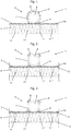
- FIG. 1 an embodiment of a surface temperature control system 1 according to the present invention is shown in a cross-sectional view.
- the surface temperature control system 1 according to the invention according to this embodiment comprises a flexible plastic tube 2, a carrier foil 3 and a dimensionally stable, flat carrier 4.
- the outside of the flexible plastic tube 2 is formed in the form of spirals of a first element 5 of a Velcro connection 6.
- the flexible plastic tube 2 comprises a first layer 7 of polymeric material, which surrounds a lumen 8 for guiding a heat transfer medium.
- the first layer 7 is made of peroxide-crosslinked polyethylene (PE-Xa), around which an adhesion promoter layer and a diffusion barrier layer are arranged in the stated order.
- the first layer 7 is preferably oxygen-tight in accordance with DIN 4726.
- the first layer 7 is preferably produced by coextrusion.
- the outside of the flexible plastic tube 2 forms the first element 5 of the Velcro connection 6, which is designed as bands, which are arranged in the form of substantially mutually parallel spirals around the first layer 7.
- the first layer 7 is partially encased by the first element 5 of the Velcro connection 6.
- the first element 5 of the Velcro connection 6 comprises hooks, fibers or the like.
- a further layer of foamed polyethylene is attached, which is a flexible elastic sheath 9 represents.
- the flexible elastic sheath 9 is in turn connected via an adhesive connection with the first element 5 of the Velcro connection 6.
- the flexible plastic tube 2 may be formed without the flexible elastic sheath 9.
- the flexible plastic tube 2 is applied therein on the carrier film 3, which is glued over the entire surface on the dimensionally stable sheet-metal carrier 4.
- the carrier film 3 can also be applied in a strip-shaped, punctiform or in a combination of said geometries.
- the carrier foil 3 On its side facing the flexible plastic tube 2, the carrier foil 3 comprises a second element 10 of the Velcro connection 6, which is formed as knitted fabric, alternatively it can also be formed as fleece, velvet fabric, plush, terry or other textile fabric.
- the flexible plastic tube 2, on the outside of which the first element 5 of the Velcro connection 6 is located, is releasably fixed to the second element 10 with formation of the Velcro connection 6 on the carrier foil 3.
- the carrier film 3 comprises a film or a composite film, to which the second element 10 of the Velcro connection 6 is glued or laminated.
- the carrier film 3 comprises a carrier layer formed in particular as a polymer layer, preferably as a polyethylene layer, which in turn is connected to a paper carrier layer via an adhesive layer. This is followed by an aluminum foil and a likewise formed as a polymer layer, in particular as a polyethylene layer protective layer.
- the carrier film 3 may be formed as a single-layer film, in particular as a polymer film, preferably as a polyethylene film.
- the carrier film 3 On its side facing away from the flexible plastic pipe 2, the carrier film 3 is glued over its entire surface or partially onto the dimensionally stable, flat carrier 4, which is designed as an insulating mat 4.
- the insulating mat 4 is preferably made of mineral wool or other fiber material and is used for heat and impact sound insulation.
- the insulating mat 4 is crossed over its entire material thickness by a plurality of stabilizing seams 11, 11 ', 11 ", 11''' The stabilizing seams 11, 11 ', 11', 11 '''stabilize the inner structure of the insulating mat 4, see FIG that it forms a compact composite.
- the connecting seams on both sides of the insulating mat which further increases the compactness of the resulting composite body and its stability contributes.
- the stabilizing seams 11, 11 ', 11 ", 11''' do not damage the carrier film 3. This is not perforated, so that the function of the carrier film 3 as a liquid-tight protective layer, in particular against the penetration of screed mixing water or of liquid screed itself into the underlying screed Insulation layer is given.
- FIG. 2 and Fig. 3 further embodiments of the surface temperature control system 1 according to the invention are shown with reference to cross-sectional views. To avoid repetition, therefore, below are only differences to those in Fig. 1 illustrated embodiment of the surface temperature control system 1 according to the invention described. The embodiments too Fig. 1 also apply to the embodiments according to Fig. 2 and Fig. 3 corresponding. Like elements are indicated in the figures by identical reference numerals.
- FIG. 2 A further embodiment of a surface temperature control system 1 according to the present invention is shown in a cross-sectional representation. A difference of this further embodiment from that in FIG Fig. 1
- a surface temperature control system 1 The outside of the flexible plastic tube 2 is in turn formed in the form of spirals of a first element 5 of a Velcro connection 6.
- a layer of foamed polyethylene is arranged over the entire surface by means of an adhesive connection.
- This flexible elastic sheath 9 thus also encases the first layer 7 in FIG the shape of substantially mutually parallel spirals whose course corresponds in each case to the course of the spirals of the first element 5 of the Velcro connection 6.
- the flexible elastic sheath 9 is in turn connected via an adhesive connection with the first layer 8 of the plastic tube 2.
- the first layer 8 is extruded from a polyethylene with increased temperature resistance in accordance with ISO 24033 (PE-RT).
- a cover layer 12 is sewn on the side of the insulating mat 4, which carries the second element 10 of the Velcro connection 6.
- the sewn cover layer 12 is in the in Fig. 2 illustrated embodiment formed as a mesh fabric.
- the cover layer 12 prevents the stabilization seams 11, 11 ', 11 ", 11''from being leached out of the insulating mat 4 under high load
- the cover layer 11 can also be made of a mineral raw material as a layer of a plastic, from a renewable raw material , be made of textile, paper, glass fleece, aluminum, etc., or of a composite material of the materials mentioned.
- FIG Fig. 3 Another embodiment of a surface temperature control system 1 according to the present invention is shown in FIG Fig. 3 again shown in a cross-sectional view.
- a difference of this further embodiment from that in Fig. 1 embodiment shown also lies according to this embodiment in the flexible plastic tube 2, which in the embodiment according to Fig. 3 identical to the flexible plastic tube 2 in Fig. 2 is designed.
- a cover layer 12 is also sewn on the side of the insulating mat 4 by the stabilizing seams 11, 11 ', 11 ", 11''' on the side of the insulating mat 4, which carries the second element 10 of the Velcro connection 6.
- a further cover layer 13 which is also sewn by the stabilizing seams 11, 11 ', 11 ", 11''' with the insulation mat 4.
- the risk of the stabilizing seams 11, 11 ', 11 ", 11''' separating out under load from the material of the insulating mat 4 is even more reduced
- the lower cover layer 13 may also be provided as a layer of a plastic, a renewable raw material, a mineral raw material, textile, paper, Glass fleece, aluminum, etc. or consist of a composite material of said materials or be designed as a mesh fabric.
Landscapes
- Engineering & Computer Science (AREA)
- General Engineering & Computer Science (AREA)
- Mechanical Engineering (AREA)
- Physics & Mathematics (AREA)
- Thermal Sciences (AREA)
- Chemical & Material Sciences (AREA)
- Combustion & Propulsion (AREA)
- Laminated Bodies (AREA)
Abstract
Description
- Die vorliegende Erfindung betrifft ein Flächentemperierungssystem, das mindestens ein flexibles Kunststoffrohr, dessen Außenseite zumindest teilweise von einem ersten Element einer Klettverbindung ummantelt ist; eine Trägerfolie, wobei an einer Seite der Trägerfolie ein zweites Element der Klettverbindung angeordnet ist, so dass das/die flexible(n) Kunststoffrohr(e) lösbar unter Bildung der Klettverbindung an der Trägerfolie festlegbar ist/sind; und einen formstabilen, flächigen Träger, der als wärme- und trittschalldämmende Dämmstoffmatte mit einer Mehrzahl von Stabilisierungsnähten ausgebildet ist, umfasst.
- Flächentemperierungssysteme und darin einsetzbare flexible Kunststoffrohre sind aus dem Stand der Technik bekannt. Derartige Flächentemperierungssysteme werden zum Heizen und Kühlen von Räumen eingesetzt, wobei in Fußböden, Wänden oder Decken verlegte, von einem Wärmeträgermedium durchströmte Rohrleitungen in einer Estrich-, Putz- oder Betonschicht in Fußböden, Wänden oder Decken eingegossen sind. Vor dem Vergießen mit Estrich sind die Rohrleitungen üblicherweise durch geeignete Schienen oder Halter auf Trägern fixiert. Zur einfacheren und schnelleren Verlegung ist es bekannt, die Rohrleitungen mittels einer Klettverbindung auf den Trägern festzulegen. Beispielsweise beschreibt die
DE 20 2010 009 133 U1 ein Flächentemperierungssystem mit einer Klett-Faserplatte aus einem formstabilen flächigen Träger mit einer Dicke zwischen 2,5 mm und 7 mm, auf den eine gewebeverstärkte Folie aufgebracht ist, die ein erstes Element einer Klettvorrichtung bildet, und einem flexiblen Rohr, das zumindest teilweise mit einem zweiten Element der Klettvorrichtung ummantelt ist. Der formstabile, flächige Träger wird vor dem Aufbringen des flexiblen Kunststoffrohrs und dem Vergießen mit Estrich auf einer zusätzlich erforderlichen Dämmstoffschicht verlegt. Nachteilig an dem in derDE 20 2010 009 133 U1 beschriebenen Flächentemperierungssystem wird gesehen, dass der dünne formstabile flächige Träger die hohen Anforderungen an die Mindestwärmeleitwiderstände von Dämmstoffmaterialien unter Flächentemperierungssystemen, wie sie in der EN 1264 normiert sind, nicht erfüllt. Hierzu ist zusätzlich eine bauseitig verlegte Dämmstoffschicht erforderlich, was einen weiteren kostenintensiven Arbeitsschritt bei der Installation der Flächentemperierungssysteme erforderlich macht. - Zur Lösung dieses Problems schlägt die
DE 20 2015 100 914 U1 einen formstabilen, flächigen Träger vor, der als Dämmstoffschicht ausgebildet ist, wobei die ein Element der Klettverbindung tragende Trägerfolie an die Dämmschicht geheftet oder mit der Dämmschicht vernäht, verdrillt oder verflochten ist. Nachteilig daran wird angesehen, dass durch die Befestigung der Trägerfolie an der Dämmschicht mittels Anheften, Vernähen, Verdrillen oder Verflechten die Trägerfolie perforiert wird. Durch die mechanische Belastung auf der Baustelle einerseits sowie durch die Rückstellkräfte der flexiblen Kunststoffrohre andererseits besteht die Gefahr, dass die durch die Nähte verursachten Löcher in der Trägerfolie noch vergrößert werden. Die Funktion der Trägerfolie als flüssigkeitsdichte Schutzschicht ist dadurch beeinträchtigt. Beispielsweise kann Estrichanmachwasser in die Dämmstoffschicht eindringen, Feuchteschäden verursachen und die Funktion als Wärme- und Trittschalldämmung negativ beeinflussen. Faserdämmstoffe sind hier aufgrund ihrer Struktur besonders gefährdet. - An dieser Stelle setzt die vorliegende Erfindung ein, deren Aufgabe darin liegt, ein Flächentemperierungssystem zur Verfügung zu stellen, das die Nachteile des Stands der Technik überwindet. Insbesondere soll das erfindungsgemäße Flächentemperierungssystem feuchtigkeitsdicht sein. Darüber hinaus soll das erfindungsgemäße Flächentemperierungssystem einen einfachen Aufbau aufweisen und leicht verlegbar sein.
- Diese und andere Aufgaben werden durch ein Flächentemperierungssystem mit den Merkmalen des Anspruchs 1 gelöst. Bevorzugte Ausführungsformen des erfindungsgemäßen Flächentemperierungssystems sind in den abhängigen Ansprüchen beschrieben.
- Gemäß der vorliegenden Erfindung wurde erkannt, dass die Gefahr des Eindringens von Wasser, insbesondere von Estrichanmachwasser, in das Dämmmaterial der Dämmstoffschicht dadurch beseitigt werden kann, dass die Trägerfolie in anderer Weise auf eine Seite der Dämmstoffmatte aufgebracht ist, ohne die Trägerfolie mit der Dämmstoffmatte zu vernähen, also beispielsweise durch Aufkleben oder Aufkaschieren. Das Aufkleben oder Aufkaschieren der Trägerfolie kann dabei vollflächig, streifenförmig, punktuell oder in einer Kombination der genannten Geometrien erfolgen. Dadurch wird die Trägerfolie nicht perforiert, so dass keine Löcher vorhanden sind, die ein Eindringen von Wasser in das Dämmmaterial erlauben würden. Durch die Trägerfolie bleibt das Dämmmaterial der Dämmstoffschicht vor Wasser geschützt, so dass diesem seine wärme- und trittschalldämmendenden Eigenschaften erhalten bleiben. Zusätzlich weist die Dämmstoffmatte eine Mehrzahl von Stabilisierungsnähten auf, durch die die Dämmstoffmatte einen kompakten Verbundkörper darstellt, der sich zum Einsatz als formstabiler, flächiger Träger eines Flächentemperierungssystems eignet.
- Dementsprechend liegt die vorliegende Erfindung in der Bereitstellung eines Flächentemperierungssystems, das mindestens ein flexibles Kunststoffrohr, dessen Außenseite zumindest teilweise von einem ersten Element einer Klettverbindung ummantelt ist; eine Trägerfolie, wobei an einer Seite der Trägerfolie ein zweites Element der Klettverbindung angeordnet ist, so dass das/die flexible(n) Kunststoffrohr(e) lösbar unter Bildung der Klettverbindung an der Trägerfolie festlegbar ist/sind; und einen formstabilen, flächigen Träger, der als wärme- und trittschalldämmende Dämmstoffmatte mit einer Mehrzahl von Stabilisierungsnähten ausgebildet ist, umfasst, wobei die Trägerfolie auf einer Seite der wärme- und trittschalldämmende Dämmstoffmatte festgelegt ist, ohne dass die Stabilisierungsnähte die Trägerfolie durchdringen.
- Wie er hierin verwendet wird, bedeutet der Begriff "Kunststoffrohr" ein Vollkunststoffrohr oder ein Metall-Kunststoff-Verbundrohr. In Bezug auf das erfindungsgemäßen Kunststoffrohr wird der Begriff "flexibel" hierin so verwendet, dass das flexible Kunststoffrohr Biegeradien ermöglicht, die zur Verlegung eines Rohres für ein Flächentemperierungssystem erforderlich sind.
- Hinsichtlich des erfindungsgemäßen Flächentemperierungssystems ist es bevorzugt, wenn die Dämmstoffmatte ein Fasermaterial, insbesondere Mineralwolle, Glaswolle, Sisal, tierische Wollen und Haare, Kokos, Heu, Getreidestroh, Hanf, Steinwolle, Holzwolle, Holzwollverbundprodukte, Bambusfasern oder einen Verbund oder Mehrlagenverbund der genannten Materialien, umfasst.
- Darüber hinaus kann es von Nutzen sein, wenn zumindest mehrere der Stabilisierungsnähte die gesamte Materialstärke der wärme- und trittschalldämmenden Dämmstoffmatte durchsetzen. Dadurch verlaufen die Verbindungsnähte auf beiden Seiten der Dämmstoffmatte, was die Kompaktheit des resultierenden Verbundkörpers weiter erhöht und zu dessen Stabilität beiträgt. Darüber hinaus ist das Risiko verringert, dass die Stabilisierungsnähte bei einwirkender Belastung aus der Dämmstoffmatte herausgerissen werden.
- Ebenso kann er hilfreich sein, wenn die Stabilisierungsnähte als Fäden, Bänder, insbesondere gurtartige Bänder, bevorzugt mit einer Breite von etwa 3 mm bis 5 mm, oder Draht, insbesondere dünne Drahtfäden, ausgebildet sind. Derartige Stabilisierungsnähte haben sich in der Praxis als besonders geeignet erwiesen.
- Ebenso kann er hilfreich sein, wenn die Stabilisierungsnähte in der Form eines Doppelkettenstiches in die Dämmstoffmatte eingreifen. Dies macht die resultierende Dämmstoffmatte noch kompakter.
- Ebenso kann es hilfreich sein, wenn durch die Stabilisierungsnähte eine Deckschicht auf eine Seite der Dämmstoffmatte aufgenäht ist. Dabei ist es besonders günstig, wenn die Deckschicht durch die Stabilisierungsnähte auf die Seite der Dämmstoffmatte aufgebracht ist, auf der dann die ein Element der Klettverbindung tragende Trägerfolie aufgebracht, insbesondere aufgeklebt, ist. Die aufgenähte Deckschicht kann aus einem Kunststoff, aus einem nachwachsendem Rohstoff, aus einem mineralischen Rohstoff, aus Textil, Papier, Glasvlies, Aluminium, etc. oder aus einem Verbundmaterial aus den genannten Werkstoffen bestehen. Alternativ kann die aufgenähte Deckschicht auch ein Gittergewebe sein. Bevorzugt ist die Deckschicht jedoch eine Kunststofffolie, besonders bevorzugt eine Kunststofffolie mit einem niedrigen Dampfdiffusionswiderstand.
- Die Dämmstoffmatte kann als Einzelplatte, als Faltplatte oder auch als Rollenware ausgebildet sein.
- Zur Verbindung zweier formstabiler, flächiger Träger eines erfindungsgemäßen Flächentemperierungssystems kann die Deckschicht und/oder die Trägerfolie wenigstens an einer Seite über den Rand der Dämmstoffmatte hinausragen. Die resultierenden Überlappungsstreifen, die bevorzugt über selbstklebende Eigenschaften verfügen, überlappen beim Verlegen eine benachbarte Dämmstoffmatte. Dadurch wird sehr einfach eine gegenüber Wasser undurchlässige Abdeckschicht für den aufzubringenden Estrich (angelehnt an die DIN 18560) oder Gussasphalt erzeugt.
- Ebenso kann er hilfreich sein, wenn an der der Trägerfolie gegenüberliegenden Seite der Dämmstoffmatte eine untere Deckschicht angeordnet ist, die vorzugsweise ebenfalls an die Dämmstoffmatte angenäht ist. Dadurch wird die Gefahr, dass sich die Stabilisierungsnähte aus dem Material der Dämmstoffmatte heraustrennen weiter verringert. Die untere Deckschicht ist vorzugsweise als Verbundfolie ausgebildet, die besonders bevorzugt eine Metallschicht, vorzugsweise eine Aluminiumschicht, umfasst. Durch einen derartigen Aufbau lassen sich die isolierenden Eigenschaften des formstabilen, flächigen Trägers weiter erhöhen. Dabei ist es besonders hilfreich, wenn die untere Deckschicht neben der Metallschicht eine Trägerschicht, vorzugsweise aus Papier, und/oder eine Schutzschicht, vorzugsweise aus Polymermaterial, insbesondere Polyethylen oder Polypropylen, umfasst. Alternativ kann die untere Deckschicht auch aus einem Kunststoff, aus einem nachwachsendem Rohstoff, aus einem mineralischen Rohstoff, aus Textil, Papier, Glasvlies, Aluminium, etc. oder aus einem Verbundmaterial aus den genannten Werkstoffen bestehen oder auch ein Gittergewebe sein.
- Hinsichtlich der Trägerfolie es weiter bevorzugt, wenn die Trägerfolie als Verbundfolie ausgebildet ist, die insbesondere an ihrer dem formstabilen, flächigen Trägern zugewandten Seite eine Metallschicht, vorzugsweise eine Aluminiumschicht, umfasst. Dabei ist es besonders bevorzugt, wenn die Trägerfolie neben der Metallschicht eine Trägerschicht, vorzugsweise aus Papier, und eine Schutzschicht, vorzugsweise aus Polymermaterial, insbesondere Polyethylen oder Polypropylen, umfasst.
- Die Trägerfolie ist bevorzugt flächig mit dem zweiten Element der Klettverbindung versehen, vorzugsweise ist die gesamte Fläche der Trägerfolie mit dem zweiten Element der Klettverbindung versehen. Die so gebildete flächige Klettverbindung ermöglicht eine Rohrverlegung auf der gesamten Fläche der Trägerfolie in einem nahezu beliebigen Verlegemuster. Die Trägerfolie ist bevorzugt flächig oder partiell auf die Dämmstoffmatte oder die Deckschicht aufgebracht, insbesondere aufgeklebt oder aufkaschiert. Die Anbindung der Trägerfolie kann dabei vollflächig oder mit Unterbrechungen erfolgen.
- Hinsichtlich des flexiblen Kunststoffrohrs des erfindungsgemäßen Flächentemperierungssystems ist es bevorzugt, wenn das flexible Kunststoffrohr zwischen einer ersten Schicht aus polymerem Material, die ein Lumen des Kunststoffrohres umgibt, und dem ersten Element der Klettverbindung eine flexible, elastische Ummantelung umfasst. Beim Verlegen des flexiblen Kunststoffrohrs auf dem mit der Trägerfolie versehenen formstabilen flächigen Träger passt sich die flexible, elastische Ummantelung aufgrund ihrer Elastitzität an die Oberfläche der Trägerfolie an, wenn auf das flexible Kunststoffrohr von außen Druck ausgeübt wird, beispielsweise indem der Verleger mit dem Fuß auf das erfindungsgemäße flexible Kunststoffrohr steigt oder mit der darauf drückt oder darüber streicht. Dadurch wird die Kontaktfläche zwischen dem flexiblen Kunststoffrohr und der Trägerfolie vergrößert, was zu einer stärker ausgebildeten Klettverbindung führt. Nach Wegfall des Drucks auf das flexible Kunststoffrohr bleibt diese Kontaktfläche aufgrund der Klettverbindung im Wesentlichen unverändert. Darüber hinaus kann das flexible Kunststoffrohr beliebig auf dem mit der Trägerfolie versehenen formstabilen flächigen Träger ohne festgelegte Verlegerichtung verlegt werden. Zur Korrektur der Verlegung kann die Klettverbindung gelöst und das Rohr in der gewünschten Anordnung verlegt werden. Dies erlaubt so eine flexible Rohrverlegung, die sich an unterschiedliche Raumgeometrien anpassen lässt. Ein Aufschwimmen des erfindungsgemäßen flexiblen Kunststoffrohrs im frisch verlegten Estrich ist weitestgehend ausgeschlossen.
- Bevorzugt handelt es sich bei dem polymeren Material der ersten Schicht des flexiblen Kunststoffrohrs um vernetztes Polyethylen (PE-X) oder PE-RT. Wie er hierin verwendet wird, bedeutet der Begriff "PE-RT" ein Polyethylen mit erhöhter Temperaturbeständigkeit gemäß ISO 24033. Eine erste Schicht aus PE-X ist aufgrund der thermischen und mechanischen Eigenschaften (wie Schlagzähigkeit, Knickfestigkeit, Punktlastbeständigkeit) bevorzugt. Wie hierin verwendet wird, bedeutet der Begriff "PE-X" vernetztes Polyethylen, wobei Peroxid-vernetztes Polyethylen (PE-Xa), Silan-vernetztes Polyethylen (PE-Xb), Elektronenstrahl-vernetztes Polyethylen (PE-Xc) sowie azovernetztes Polyethylen (PE-Xd) umfasst sind. Gemäß der vorliegenden Erfindung wird Peroxid-vernetztes Polyethylen (PE-Xa) als bevorzugtes polymeres Material der ersten Schicht eingesetzt. Die Vernetzung zum vernetzten Polyethylen erfolgt vorzugsweise wie in der
DE 102 51 152 B4 beschrieben. Darüber hinaus kann das polymere Material der ersten Schicht weiter einen Haftvermittler (vorzugsweise ein funktionalisiertes Polyolefinen, insbesondere ein Maleinsäureanhydridgepfropftes LLDPE (lineares Polyethylen geringerer Dichte)) und/oder eine Diffusionssperrschicht, insbesondere aus Polyvinylakohol (PVA) oder Ethylen-Vinylalkohol-Copolymer (EVOH) umfassen. - Darüber hinaus kann es sich als günstig erweisen, wenn das erste Element der Klettverbindung spiralförmig oder doppelspiralförmig an der Außenseite des flexiblen Kunststoffrohrs angeordnet ist. Bei geringem Materialaufwand sorgt dies für eine dennoch hohe Häufigkeit der Kontaktstellen zwischen dem flexiblen Kunststoffrohr und dem Trägerfolie. Dabei hat es sich als materialeinsparend und damit kostengünstig erwiesen, wenn die flexible, elastische Ummantelung die erste Schicht aus polymerem Material teilweise ummantelt. Eine besonders effektive Variante hinsichtlich Materialaufwand für die flexible elastische Schicht und hoher Kontaktfläche zwischen dem flexiblen Kunststoffrohr und der Trägerfolie liegt in diesem Zusammenhang insbesondere dann vor, wenn die flexible, elastische Ummantelung an der der ersten Schicht zugewandten Seite des ersten Elements der Klettverbindung angeordnet ist und dem Verlauf des ersten Elements der Klettverbindung an der Außenseite des flexiblen Kunststoffrohrs folgt.
- Die flexible, elastische Ummantelung kann die erste Schicht des flexiblen Kunststoffrohrs auch vollständig ummantelt. Dazu kann die flexible, elastische Ummantelung im Rahmen einer Coextrusion unmittelbar oder unter Einsatz einer Haftvermittlerschicht auf die erste Schicht aufgebracht werden. Eine bevorzugte einfache Verbindung zwischen der flexiblen, elastischen Ummantelung sowie der ersten Schicht und/oder dem ersten Element der Klettverbindung erfolgt über eine Klebstoffschicht. Die flexible, elastische Ummantelung kann aus einem flexiblen Material, wie einem geschäumten Kunststoff (z.B. ein geschäumtes Polyethylen oder Polyurethan) hergestellt sein. Die flexible, elastische Ummantelung gibt dann bei Einwirkung eines äußeren Drucks aufgrund ihrer Flexibilität nach und ermöglicht auf diese Weise beim Aufdrücken des Kunststoffrohres auf die Trägerfolie die Ausbildung einer vergrößerten Auflagefläche und somit einer stärkeren Klettverbindung zwischen erfindungsgemäßem Kunststoffrohr und Trägerfolie.
- Gemäß einer Ausführungsform der vorliegenden Erfindung wird ein Element der Klettverbindung durch Haken, Schlingen und/oder Fasern gebildet, die in ein Gewirke, ein Vlies, ein Veloursgewebe oder dergleichen des anderen Elements der Klettverbindung lösbar eingreifen können. Die Klettverbindung gewährleistet so eine lösbare Verbindung zwischen der Trägerfolie und dem flexiblen Kunststoffrohr, wodurch das flexible Kunststoffrohr auf der Trägerfolie reversibel festgelegt wird. Dabei ist es bevorzugt, wenn das erste Element der Klettverbindung die Haken, Schlingen und/oder Fasern aufweist, während das zweite Element der Klettverbindung durch das Gewirke, das Vlies, das Veloursgewebe oder ein Plüsch-, Frottee- oder sonstiges textiles Flächengebilde gebildet wird. Umgekehrt ist auch möglich, dass das erste Element der Klettverbindung durch das Gewirke, das Vlies, das Veloursgewebe, das Plüsch-, Frottee- oder sonstiges textiles Flächengebilde gebildet wird, während das zweite Element der Klettverbindung die Haken, Schlingen und/oder Fasern aufweist.
- Das erfindungsgemäße Flächentemperierungssystem sowie einzelne Teile davon können auch zeilenweise oder schichtweise unter Verwendung eines zeilenaufbauenden oder schichtaufbauenden Fertigungsverfahrens (z. B. 3D-Druck) hergestellt werden.
- Im Folgenden soll die vorliegende Erfindung unter Bezugnahme auf die in den Figuren dargestellten Ausführungsformen im Detail erläutert werden. Insoweit sich Teile oder Bauelemente in ihrer Funktion entsprechen, wird deren Beschreibung nicht in jeder der folgenden Figuren wiederholt. Es zeigen:
-
Fig. 1 eine Querschnittsdarstellung eines Flächentemperierungssystems gemäß einer Ausführungsform der vorliegenden Erfindung; -
Fig. 2 eine Querschnittsdarstellung eines Flächentemperierungssystems gemäß einer Ausführungsform der vorliegenden Erfindung; und -
Fig. 3 eine Querschnittsdarstellung eines Flächentemperierungssystems gemäß einer weiteren Ausführungsform der vorliegenden Erfindung. - In
Fig. 1 ist eine Ausführungsform eines Flächentemperierungssystems 1 gemäß der vorliegenden Erfindung in einer Querschnittsdarstellung gezeigt. Das erfindungsgemäße Flächentemperierungssystem 1 gemäß dieser Ausführungsform umfasst ein flexibles Kunststoffrohr 2, eine Trägerfolie 3 sowie einen formstabilen, flächigen Träger 4. - Die Außenseite des flexiblen Kunststoffrohrs 2 ist in Form von Spiralen von einem ersten Element 5 einer Klettverbindung 6 gebildet. Das flexible Kunststoffrohr 2 umfasst eine erste Schicht 7 aus polymerem Material, die ein Lumen 8 zur Führung eines Wärmeträgermediums umgibt. In der in
Fig.1 dargestellten Ausführungsform ist die erste Schicht 7 aus Peroxid-vernetztem Polyethylen (PE-Xa), um das herum in der angegeben Reihenfolge eine Haftvermittlerschicht und eine Diffusionssperrschicht angeordnet sind. Bevorzugt ist die erste Schicht 7 sauerstoffdicht gemäß DIN 4726. Die erste Schicht 7 wird vorzugsweise durch Coextrusion hergestellt. Die Außenseite des flexiblen Kunststoffrohres 2 bildet das erste Element 5 der Klettverbindung 6, das als Bänder ausgebildet ist, die in Form von im Wesentlichen parallel zueinander verlaufenden Spiralen um die erste Schicht 7 angeordnet sind. Damit ist die erste Schicht 7 von dem ersten Element 5 der Klettverbindung 6 teilweise ummantelt. Das erste Element 5 der Klettverbindung 6 umfasst Haken, Fasern oder ähnliches. Um die erste Schicht 7 des flexiblen Kunststoffrohres 2 herum ist über die gesamte Fläche mittels einer Haftvermittlerschicht und/oder einer Klebstoffverbindung eine weitere Schicht aus geschäumtem Polyethylen befestigt, die eine flexible elastische Ummantelung 9 darstellt. Die flexible elastische Ummantelung 9 ist wiederum über eine Klebstoffverbindung mit dem ersten Element 5 der Klettverbindung 6 verbunden. In alternativen Ausführungsformen kann das flexible Kunststoffrohr 2 auch ohne die flexible elastische Ummantelung 9 ausgebildet sein. - Das flexible Kunststoffrohr 2 ist darin auf die Trägerfolie 3 aufgebracht, die vollflächig auf den formstabilen flächigen Träger 4 aufgeklebt ist. In alternativen Ausführungsformen der vorliegenden Erfindung kann die Trägerfolie 3 auch streifenförmig, punktuell oder in einer Kombination der genannten Geometrien aufgebracht sein. An ihrer dem flexiblen Kunststoffrohr 2 zugewandten Seite umfasst die Trägerfolie 3, ein zweites Element 10 der Klettverbindung 6, das als Gewirke ausgebildet ist, alternativ auch als Vlies, Veloursgewebe, Plüsch-, Frottee- oder sonstiges textiles Flächengebilde ausgebildet sein kann. Das flexible Kunststoffrohr 2, an dessen Außenseite sich das erste Element 5 der Klettverbindung 6 befindet, ist auf das zweite Element 10 lösbar unter Ausbildung der Klettverbindung 6 an der Trägerfolie 3 festgelegt.
- Die Trägerfolie 3 umfasst eine Folie oder eine Verbundfolie, auf die das zweite Element 10 der Klettverbindung 6 aufgeklebt oder aufkaschiert ist. Die Trägerfolie 3 umfasst in dieser Ausführungsform eine insbesondere als Polymerschicht, vorzugsweise als Polyethylenschicht ausgebildete Trägerschicht, die über eine Klebstoffschicht wiederum mit einer Papierträgerschicht verbunden ist. Daran schließt sich eine Aluminiumfolie sowie eine ebenfalls als Polymerschicht, insbesondere als Polyethylenschicht ausgebildete Schutzschicht an. In anderen Ausführungsformen kann die Trägerfolie 3 als eine einschichtige Folie, insbesondere als Polymerfolie, vorzugsweise als Polyethylenfolie ausgebildet sein.
- An ihrer dem flexiblen Kunststoffrohr 2 abgewandten Seite ist die Trägerfolie 3 vollflächig oder partiell auf den formstabilen, flächigen Träger 4 aufgeklebt, der als Dämmstoffmatte 4 ausgebildet ist. Die Dämmstoffmatte 4 ist vorzugsweise aus Mineralwolle oder einem anderen Fasermaterial hergestellt und dient zur Wärme- und Trittschalldämmenung. Die Dämmstoffmatte 4 ist über ihre gesamte Materialdicke von einer Mehrzahl von Stabilisierungsnähten 11, 11', 11", 11''' durchzogen. Die Stabilisierungsnähte 11, 11', 11", 11''' stabilisieren die innere Struktur der Dämmstoffmatte 4, so dass sie einen kompakten Verbundkörper bildet. Durch das vollständige Durchdringen der gesamten Materialdicke der Dämmstoffmatte 4 verlaufen die Verbindungsnähte auf beiden Seiten der Dämmstoffmatte, was die Kompaktheit des resultierenden Verbundkörpers weiter erhöht und zu dessen Stabilität beiträgt. Darüber hinaus verletzen die Stabilisierungsnähte 11, 11', 11", 11''' die Trägerfolie 3 nicht. Diese wird nicht perforiert, so dass die Funktion der Trägerfolie 3 als flüssigkeitsdichte Schutzschicht insbesondere gegen das Eindringen von Estrichanmachwasser oder von Fließestrich selbst in die darunterliegende Dämmschicht gegeben ist.
- Zum Verlegen eines als Fußbodenheizung ausgebildeten erfindungsgemäßen Flächentemperierungselements 1 wird der mit der Trägerfolie 3 versehene formstabile, flächige Träger 4 zunächst auf dem Boden oder einer Zusatzdämmung vollflächig ggf. nach vorherigem Zuschneiden ausgelegt. Die Stöße zweier benachbarter formstabiler, flächiger Träger 4 werden vorzugsweise mit Randdämmstreifen untereinander flüssigkeitsdicht verklebt, insbesondere durch Überlappungsstreifen, die vorzugsweise als selbstklebend ausgeführt sind. Daraufhin wird das flexible Kunststoffrohr 2 im gewünschten Muster auf der Trägerfolie 3 verlegt und angedrückt, so dass die Klettverbindung 6 ausgebildet wird. Zur Korrektur des Verlegemusters kann die reversibel ausgebildete Klettverbindung 6 durch Anheben des flexiblen Kunststoffrohrs 2 von der Trägerfolie 3 gelöst und in einem geänderten Verlegemuster wieder auf diese aufgebracht werden. Abschließend wird die Anordnung mit Estrich vergossen.
- In
Fig. 2 und Fig. 3 sind weitere Ausführungsformen des erfindungsgemäßen Flächentemperierungssystems 1 anhand von Querschnittsdarstellungen gezeigt. Um Wiederholungen zu vermeiden, werden daher im Folgenden nur Unterschiede zu der inFig. 1 dargestellten Ausführungsform des erfindungsgemäßen Flächentemperierungssystems 1 beschrieben. Die Ausführungsformen zuFig. 1 gelten auch für die Ausführungsformen gemäßFig. 2 und Fig. 3 entsprechend. Gleiche Elemente sind in den Abbildungen durch identische Bezugszeichen gekennzeichnet. - In
Fig. 2 ist eine weitere Ausführungsform eines Flächentemperierungssystems 1 gemäß der vorliegenden Erfindung in einer Querschnittsdarstellung gezeigt Ein Unterschied dieser weiteren Ausführungsform zu der inFig. 1 gezeigten Ausführungsform liegt in der Art des flexiblen Kunststoffrohrs 2. In dieser Ausführungsform eines Flächentemperierungssystems 1. Die Außenseite des flexiblen Kunststoffrohrs 2 ist wiederum in Form von Spiralen von einem ersten Element 5 einer Klettverbindung 6 gebildet. An der dem ersten Element 5 der Klettverbindung 6 abgewandten Seite der zweiten Schicht 4 ist über die gesamte Fläche mittels einer Klebstoffverbindung eine Schicht aus geschäumtem Polyethylen angeordnet. Diese flexible elastische Ummantelung 9 ummantelt die erste Schicht 7 somit ebenfalls in der Form von im Wesentlichen parallel zueinander verlaufenden Spiralen, deren Verlauf jeweils dem Verlauf der Spiralen des ersten Elements 5 der Klettverbindung 6 entspricht. Die flexible elastische Ummantelung 9 ist wiederum über eine Klebstoffverbindung mit der ersten Schicht 8 des Kunststoffrohres 2 verbunden. In der inFig.2 dargestellten Ausführungsform ist die erste Schicht 8 aus einem Polyethylen mit erhöhter Temperaturbeständigkeit gemäß ISO 24033 (PE-RT) extrudiert. - Darüber hinaus ist durch die Stabilisierungsnähte 11, 11', 11", 11''' eine Deckschicht 12 auf der Seite der Dämmstoffmatte 4 aufgenäht, die das zweite Element 10 der Klettverbindung 6 trägt. Die aufgenähte Deckschicht 12 ist in der in
Fig. 2 dargestellten Ausführungsform als ein Gittergewebe ausgebildet. Die Deckschicht 12 verhindert ein Herauslösen der Stabilisierungsnähte 11, 11', 11", 11''' aus der Dämmmatte 4 unter hoher Belastung. Alternativ kann die Deckschicht 11 auch als eine Schicht aus einem Kunststoff, aus einem nachwachsendem Rohstoff, aus einem mineralischen Rohstoff, aus Textil, Papier, Glasvlies, Aluminium, etc. oder aus einem Verbundmaterial aus den genannten Werkstoffen ausgebildet sein. - Eine weitere Ausführungsform eines Flächentemperierungssystems 1 gemäß der vorliegenden Erfindung ist in
Fig. 3 wiederum in einer Querschnittsdarstellung gezeigt. Ein Unterschied dieser weiteren Ausführungsform zu der inFig. 1 gezeigten Ausführungsform liegt auch gemäß dieser Ausführungsform in dem flexiblen Kunststoffrohr 2, das in der Ausführungsform gemäßFig. 3 identisch zu dem flexiblen Kunststoffrohr 2 inFig. 2 ausgestaltet ist. Darüber hinaus ist auch gemäß dieser Ausführungsform des Flächentemperierungssystems 1 durch die Stabilisierungsnähte 11, 11', 11", 11''' auf der Seite der Dämmstoffmatte 4, die das zweite Element 10 der Klettverbindung 6 trägt, eine Deckschicht 12 aufgenäht. Ferner ist auch an der dem flexiblen Kunststoffrohr 2 gegenüberliegenden Seite der Dämmstoffmatte 4 eine weitere Deckschicht 13 angeordnet, die ebenfalls durch die Stabilisierungsnähte 11, 11', 11", 11''' mit der Dämmstoffmatte 4 vernäht ist. Dadurch wird die Gefahr, dass sich die Stabilisierungsnähte 11, 11', 11", 11''' aus dem Material der Dämmstoffmatte 4 unter Belastung heraustrennen, noch stärker reduziert. Auch die untere Deckschicht 13 ist in der inFig. 3 dargestellten Ausführungsform als Verbundfolie ausgestaltet, die eine Metallschicht, insbesondere eine Aluminiumschicht, sowie eine Polymerschicht, insbesondere eine Polyethylenschicht, als Schutzschicht umfasst. In alternativen Ausführungsformen kann die untere Deckschicht 13 auch als eine Schicht aus einem Kunststoff, aus einem nachwachsendem Rohstoff, aus einem mineralischen Rohstoff, aus Textil, Papier, Glasvlies, Aluminium, etc. oder aus einem Verbundmaterial aus den genannten Werkstoffen bestehen oder auch als ein Gittergewebe ausgebildet sein. - Das Verlegen eines als Fußbodenheizung ausgebildeten erfindungsgemäßen Flächentemperierungselements 1 erfolgt in der in Bezug auf die
Fig. 1 erläuterten Art und Weise. - Die vorliegende Erfindung wurde unter Bezugnahme auf die in den Figuren gezeigte Ausführungsform der vorliegenden Erfindung im Detail beschrieben. Es versteht sich, dass die vorliegende Erfindung nicht auf die gezeigte Ausführungsform beschränkt ist, sondern sich der Umfang der vorliegenden Erfindung aus den beiliegenden Ansprüchen ergibt.
Claims (6)
- Flächentemperierungssystem (1), umfassend:- mindestens ein flexibles Kunststoffrohr (2), dessen Außenseite zumindest teilweise von einem ersten Element (5) einer Klettverbindung (6) ummantelt ist;- eine Trägerfolie (3), wobei an einer Seite der Trägerfolie (3) ein zweites Element (10) der Klettverbindung (6) angeordnet ist, so dass das/die flexible(n) Kunststoffrohr(e) (2) lösbar unter Bildung der Klettverbindung (6) an der Trägerfolie (3) festlegbar ist/sind; und- einen formstabilen, flächigen Träger (4), der als wärme- und trittschalldämmende Dämmstoffmatte (4) mit einer Mehrzahl von Stabilisierungsnähten (11, 11', 11", 11''') ausgebildet ist;dadurch gekennzeichnet, dass
die Trägerfolie (3) auf einer Seite der wärme- und trittschalldämmenden Dämmstoffmatte (4) festgelegt ist, ohne dass die Stabilisierungsnähte (11, 11', 11", 11''') die Trägerfolie (3) durchdringen. - Flächentemperierungssystem (1) nach Anspruch 1, dadurch gekennzeichnet, dass die Dämmstoffmatte (4) ein Fasermaterial, insbesondere Mineralwolle, Glasfaser, Sisal, tierische Wollen und Haare, Kokos, Heu, Getreidestroh, Hanf, Steinwolle, Holzwolle, Holzwollverbundprodukte, Bambusfasern oder einen Verbund oder Mehrlagenverbund der genannten Materialien, umfasst.
- Flächentemperierungssystem (1) nach Anspruch 1 oder Anspruch 2, dadurch gekennzeichnet, dass zumindest mehrere der Stabilisierungsnähte (11, 11', 11", 11''') die gesamte Materialstärke der wärme- und trittschalldämmende Dämmstoffmatte (4) durchsetzen.
- Flächentemperierungssystem (1) nach einem Ansprüche 1 bis 3, dadurch gekennzeichnet, dass die Stabilisierungsnähte (11, 11', 11", 11''') als Fäden, Bänder oder Draht ausgebildet sind.
- Flächentemperierungssystem (1) nach einem der Ansprüche 1 bis 4, dadurch gekennzeichnet, dass die Stabilisierungsnähte (11, 11', 11", 11''') in der Form eines Doppelkettenstiches in die Dämmstoffmatte (4) eingreifen.
- Flächentemperierungssystem (1) nach einem der Ansprüche 1 bis 5, dadurch gekennzeichnet, dass durch die Stabilisierungsnähte (11, 11', 11", 11''') eine mindestens eine Deckschicht (12, 13) auf eine Seite der Dämmstoffmatte (4) aufgebracht ist.
Applications Claiming Priority (1)
| Application Number | Priority Date | Filing Date | Title |
|---|---|---|---|
| DE202016107044.9U DE202016107044U1 (de) | 2016-12-16 | 2016-12-16 | Flächentemperierungssystem |
Publications (2)
| Publication Number | Publication Date |
|---|---|
| EP3343082A1 true EP3343082A1 (de) | 2018-07-04 |
| EP3343082B1 EP3343082B1 (de) | 2020-01-29 |
Family
ID=58010892
Family Applications (1)
| Application Number | Title | Priority Date | Filing Date |
|---|---|---|---|
| EP17205351.4A Active EP3343082B1 (de) | 2016-12-16 | 2017-12-05 | Flächentemperierungssystem |
Country Status (2)
| Country | Link |
|---|---|
| EP (1) | EP3343082B1 (de) |
| DE (1) | DE202016107044U1 (de) |
Families Citing this family (3)
| Publication number | Priority date | Publication date | Assignee | Title |
|---|---|---|---|---|
| DE202017003466U1 (de) * | 2017-07-03 | 2018-10-05 | Rehau Ag + Co | Flächentemperierungssystem |
| EP3495743A1 (de) * | 2017-12-07 | 2019-06-12 | herotec GmbH Flächenheizung | Dämmungsvorrichtung für eine flächentemperierungsvorrichtung und flächentemperierungsvorrichtung mit einer dämmungsvorrichtung |
| DE202019107126U1 (de) * | 2019-12-19 | 2021-03-22 | Rehau Ag + Co | Flächentemperierungselement |
Citations (7)
| Publication number | Priority date | Publication date | Assignee | Title |
|---|---|---|---|---|
| DE29708455U1 (de) * | 1997-05-13 | 1998-09-17 | DiTom Verwaltungs GmbH, 98529 Suhl | Vorrichtung zum Befestigen von Fußbodenheizungsrohren auf Kunststoffisolierbahnen |
| DE10251152B4 (de) | 2002-10-31 | 2007-10-04 | Rehau Ag + Co. | Extrudieren von peroxidischen vernetzbaren Formteilen aus Kunststoff |
| DE202010009133U1 (de) | 2010-03-25 | 2011-08-18 | Uponor Innovation Ab | Klett-Faserplatte |
| DE202010009431U1 (de) * | 2010-06-23 | 2011-10-12 | Uponor Innovation Ab | System zur Anordnung mindestens eines Rohres |
| DE202010011520U1 (de) * | 2010-08-18 | 2011-11-23 | Uponor Innovation Ab | Klettsystem |
| DE202014104324U1 (de) * | 2014-09-12 | 2015-12-16 | Rehau Ag + Co. | Flexibles Kunststoffrohr sowie dieses umfassendes Flächentemperierungselement |
| DE202015100914U1 (de) | 2015-02-12 | 2016-05-13 | Uponor Innovation Ab | Dämmstoffmatte und Wärmetauscheranordnung |
-
2016
- 2016-12-16 DE DE202016107044.9U patent/DE202016107044U1/de not_active Expired - Lifetime
-
2017
- 2017-12-05 EP EP17205351.4A patent/EP3343082B1/de active Active
Patent Citations (7)
| Publication number | Priority date | Publication date | Assignee | Title |
|---|---|---|---|---|
| DE29708455U1 (de) * | 1997-05-13 | 1998-09-17 | DiTom Verwaltungs GmbH, 98529 Suhl | Vorrichtung zum Befestigen von Fußbodenheizungsrohren auf Kunststoffisolierbahnen |
| DE10251152B4 (de) | 2002-10-31 | 2007-10-04 | Rehau Ag + Co. | Extrudieren von peroxidischen vernetzbaren Formteilen aus Kunststoff |
| DE202010009133U1 (de) | 2010-03-25 | 2011-08-18 | Uponor Innovation Ab | Klett-Faserplatte |
| DE202010009431U1 (de) * | 2010-06-23 | 2011-10-12 | Uponor Innovation Ab | System zur Anordnung mindestens eines Rohres |
| DE202010011520U1 (de) * | 2010-08-18 | 2011-11-23 | Uponor Innovation Ab | Klettsystem |
| DE202014104324U1 (de) * | 2014-09-12 | 2015-12-16 | Rehau Ag + Co. | Flexibles Kunststoffrohr sowie dieses umfassendes Flächentemperierungselement |
| DE202015100914U1 (de) | 2015-02-12 | 2016-05-13 | Uponor Innovation Ab | Dämmstoffmatte und Wärmetauscheranordnung |
Also Published As
| Publication number | Publication date |
|---|---|
| EP3343082B1 (de) | 2020-01-29 |
| DE202016107044U1 (de) | 2017-01-25 |
Similar Documents
| Publication | Publication Date | Title |
|---|---|---|
| EP3212858B2 (de) | Flächentemperierungssystem | |
| AT12872U1 (de) | Klett-faserplatte | |
| DE202009001255U1 (de) | Schichtverbund als Träger für keramische, Stein- oder ähnliche Beläge | |
| EP2995870B1 (de) | Flächentemperierungssystem sowie Verfahren zu seiner Herstellung | |
| EP3343082B1 (de) | Flächentemperierungssystem | |
| EP3191756B1 (de) | Flexibles kunststoffrohr sowie dieses umfassendes flächentemperierungselement | |
| EP3268671B1 (de) | Rohrbund eines kunststoffrohres sowie mindestens einen von einem derartigen rohrbund abgewickelten abschnitt eines kunststoffrohres umfassendes flächentemperierungselement | |
| EP3141821A1 (de) | Unterbodendämmelement | |
| EP3144136B1 (de) | Trägerfolie für ein klettverlegesystem einer flächentemperierungsvorrichtung, dieses umfassendes flächentemperierungssystem sowie verfahren zur herstellung eines flächentemperierungssystems | |
| EP0992340A2 (de) | Mehrschichtige Schalldämmplatte | |
| EP3144138A1 (de) | Trägerfolie für ein klettverlegesystem einer flächentemperierungssystems, diese umfassendes flächentemperierungssystem sowie herstellung eines flächentemperierungssystems | |
| EP3425287B1 (de) | Flächentemperierungssystem | |
| DE202016104752U1 (de) | Fußbodendämmelement sowie Wärmetauscheranordnung | |
| DE102016124572A1 (de) | Flächentemperierungssystem | |
| EP3674611A1 (de) | Flächentemperierungssystem | |
| DE202014105276U1 (de) | Fußbodendämmelement | |
| DE202019107126U1 (de) | Flächentemperierungselement | |
| EP3967936B1 (de) | Haltefläche für ein flächentemperierungselement sowie dieses umfassendes flächentemperierungssystem | |
| EP3674612A1 (de) | Flächentemperierungssystem | |
| EP3159615A1 (de) | Haltefläche für ein flächentemperierungselement sowie dieses umfassendes flächentemperierungselement | |
| DE202018101246U1 (de) | Anordnung zur Flächentemperierung in Bereichen mit durchlaufenden Zuleitungen bzw. Anbindeleitungen für Heizkreisverteiler von Flächentemperierungen | |
| DE202017101420U1 (de) | Dämmstreifen für ein Rohr sowie diesen umfassende Rohranordnung | |
| DE19749615C2 (de) | Isolationsschlauch | |
| DE102004054099A1 (de) | Trittschalldämmung | |
| EP3115193B1 (de) | Trennbahn und verfahren zur herstellung einer trennbahn |
Legal Events
| Date | Code | Title | Description |
|---|---|---|---|
| PUAI | Public reference made under article 153(3) epc to a published international application that has entered the european phase |
Free format text: ORIGINAL CODE: 0009012 |
|
| STAA | Information on the status of an ep patent application or granted ep patent |
Free format text: STATUS: THE APPLICATION HAS BEEN PUBLISHED |
|
| AK | Designated contracting states |
Kind code of ref document: A1 Designated state(s): AL AT BE BG CH CY CZ DE DK EE ES FI FR GB GR HR HU IE IS IT LI LT LU LV MC MK MT NL NO PL PT RO RS SE SI SK SM TR |
|
| AX | Request for extension of the european patent |
Extension state: BA ME |
|
| STAA | Information on the status of an ep patent application or granted ep patent |
Free format text: STATUS: REQUEST FOR EXAMINATION WAS MADE |
|
| 17P | Request for examination filed |
Effective date: 20181220 |
|
| RBV | Designated contracting states (corrected) |
Designated state(s): AL AT BE BG CH CY CZ DE DK EE ES FI FR GB GR HR HU IE IS IT LI LT LU LV MC MK MT NL NO PL PT RO RS SE SI SK SM TR |
|
| GRAJ | Information related to disapproval of communication of intention to grant by the applicant or resumption of examination proceedings by the epo deleted |
Free format text: ORIGINAL CODE: EPIDOSDIGR1 |
|
| INTG | Intention to grant announced |
Effective date: 20190617 |
|
| INTC | Intention to grant announced (deleted) | ||
| GRAP | Despatch of communication of intention to grant a patent |
Free format text: ORIGINAL CODE: EPIDOSNIGR1 |
|
| STAA | Information on the status of an ep patent application or granted ep patent |
Free format text: STATUS: GRANT OF PATENT IS INTENDED |
|
| INTG | Intention to grant announced |
Effective date: 20190801 |
|
| GRAS | Grant fee paid |
Free format text: ORIGINAL CODE: EPIDOSNIGR3 |
|
| GRAA | (expected) grant |
Free format text: ORIGINAL CODE: 0009210 |
|
| STAA | Information on the status of an ep patent application or granted ep patent |
Free format text: STATUS: THE PATENT HAS BEEN GRANTED |
|
| AK | Designated contracting states |
Kind code of ref document: B1 Designated state(s): AL AT BE BG CH CY CZ DE DK EE ES FI FR GB GR HR HU IE IS IT LI LT LU LV MC MK MT NL NO PL PT RO RS SE SI SK SM TR |
|
| REG | Reference to a national code |
Ref country code: GB Ref legal event code: FG4D Free format text: NOT ENGLISH |
|
| REG | Reference to a national code |
Ref country code: CH Ref legal event code: EP |
|
| REG | Reference to a national code |
Ref country code: AT Ref legal event code: REF Ref document number: 1228739 Country of ref document: AT Kind code of ref document: T Effective date: 20200215 |
|
| REG | Reference to a national code |
Ref country code: IE Ref legal event code: FG4D Free format text: LANGUAGE OF EP DOCUMENT: GERMAN |
|
| REG | Reference to a national code |
Ref country code: DE Ref legal event code: R096 Ref document number: 502017003612 Country of ref document: DE |
|
| REG | Reference to a national code |
Ref country code: NL Ref legal event code: MP Effective date: 20200129 |
|
| PG25 | Lapsed in a contracting state [announced via postgrant information from national office to epo] |
Ref country code: PT Free format text: LAPSE BECAUSE OF FAILURE TO SUBMIT A TRANSLATION OF THE DESCRIPTION OR TO PAY THE FEE WITHIN THE PRESCRIBED TIME-LIMIT Effective date: 20200621 Ref country code: RS Free format text: LAPSE BECAUSE OF FAILURE TO SUBMIT A TRANSLATION OF THE DESCRIPTION OR TO PAY THE FEE WITHIN THE PRESCRIBED TIME-LIMIT Effective date: 20200129 Ref country code: FI Free format text: LAPSE BECAUSE OF FAILURE TO SUBMIT A TRANSLATION OF THE DESCRIPTION OR TO PAY THE FEE WITHIN THE PRESCRIBED TIME-LIMIT Effective date: 20200129 Ref country code: NO Free format text: LAPSE BECAUSE OF FAILURE TO SUBMIT A TRANSLATION OF THE DESCRIPTION OR TO PAY THE FEE WITHIN THE PRESCRIBED TIME-LIMIT Effective date: 20200429 |
|
| REG | Reference to a national code |
Ref country code: LT Ref legal event code: MG4D |
|
| PG25 | Lapsed in a contracting state [announced via postgrant information from national office to epo] |
Ref country code: GR Free format text: LAPSE BECAUSE OF FAILURE TO SUBMIT A TRANSLATION OF THE DESCRIPTION OR TO PAY THE FEE WITHIN THE PRESCRIBED TIME-LIMIT Effective date: 20200430 Ref country code: SE Free format text: LAPSE BECAUSE OF FAILURE TO SUBMIT A TRANSLATION OF THE DESCRIPTION OR TO PAY THE FEE WITHIN THE PRESCRIBED TIME-LIMIT Effective date: 20200129 Ref country code: IS Free format text: LAPSE BECAUSE OF FAILURE TO SUBMIT A TRANSLATION OF THE DESCRIPTION OR TO PAY THE FEE WITHIN THE PRESCRIBED TIME-LIMIT Effective date: 20200529 Ref country code: LV Free format text: LAPSE BECAUSE OF FAILURE TO SUBMIT A TRANSLATION OF THE DESCRIPTION OR TO PAY THE FEE WITHIN THE PRESCRIBED TIME-LIMIT Effective date: 20200129 Ref country code: BG Free format text: LAPSE BECAUSE OF FAILURE TO SUBMIT A TRANSLATION OF THE DESCRIPTION OR TO PAY THE FEE WITHIN THE PRESCRIBED TIME-LIMIT Effective date: 20200429 Ref country code: HR Free format text: LAPSE BECAUSE OF FAILURE TO SUBMIT A TRANSLATION OF THE DESCRIPTION OR TO PAY THE FEE WITHIN THE PRESCRIBED TIME-LIMIT Effective date: 20200129 |
|
| PG25 | Lapsed in a contracting state [announced via postgrant information from national office to epo] |
Ref country code: NL Free format text: LAPSE BECAUSE OF FAILURE TO SUBMIT A TRANSLATION OF THE DESCRIPTION OR TO PAY THE FEE WITHIN THE PRESCRIBED TIME-LIMIT Effective date: 20200129 |
|
| PG25 | Lapsed in a contracting state [announced via postgrant information from national office to epo] |
Ref country code: EE Free format text: LAPSE BECAUSE OF FAILURE TO SUBMIT A TRANSLATION OF THE DESCRIPTION OR TO PAY THE FEE WITHIN THE PRESCRIBED TIME-LIMIT Effective date: 20200129 Ref country code: SM Free format text: LAPSE BECAUSE OF FAILURE TO SUBMIT A TRANSLATION OF THE DESCRIPTION OR TO PAY THE FEE WITHIN THE PRESCRIBED TIME-LIMIT Effective date: 20200129 Ref country code: DK Free format text: LAPSE BECAUSE OF FAILURE TO SUBMIT A TRANSLATION OF THE DESCRIPTION OR TO PAY THE FEE WITHIN THE PRESCRIBED TIME-LIMIT Effective date: 20200129 Ref country code: LT Free format text: LAPSE BECAUSE OF FAILURE TO SUBMIT A TRANSLATION OF THE DESCRIPTION OR TO PAY THE FEE WITHIN THE PRESCRIBED TIME-LIMIT Effective date: 20200129 Ref country code: SK Free format text: LAPSE BECAUSE OF FAILURE TO SUBMIT A TRANSLATION OF THE DESCRIPTION OR TO PAY THE FEE WITHIN THE PRESCRIBED TIME-LIMIT Effective date: 20200129 Ref country code: CZ Free format text: LAPSE BECAUSE OF FAILURE TO SUBMIT A TRANSLATION OF THE DESCRIPTION OR TO PAY THE FEE WITHIN THE PRESCRIBED TIME-LIMIT Effective date: 20200129 Ref country code: ES Free format text: LAPSE BECAUSE OF FAILURE TO SUBMIT A TRANSLATION OF THE DESCRIPTION OR TO PAY THE FEE WITHIN THE PRESCRIBED TIME-LIMIT Effective date: 20200129 Ref country code: RO Free format text: LAPSE BECAUSE OF FAILURE TO SUBMIT A TRANSLATION OF THE DESCRIPTION OR TO PAY THE FEE WITHIN THE PRESCRIBED TIME-LIMIT Effective date: 20200129 |
|
| REG | Reference to a national code |
Ref country code: DE Ref legal event code: R097 Ref document number: 502017003612 Country of ref document: DE |
|
| RAP2 | Party data changed (patent owner data changed or rights of a patent transferred) |
Owner name: REHAU AG + CO |
|
| PLBE | No opposition filed within time limit |
Free format text: ORIGINAL CODE: 0009261 |
|
| STAA | Information on the status of an ep patent application or granted ep patent |
Free format text: STATUS: NO OPPOSITION FILED WITHIN TIME LIMIT |
|
| 26N | No opposition filed |
Effective date: 20201030 |
|
| PG25 | Lapsed in a contracting state [announced via postgrant information from national office to epo] |
Ref country code: IT Free format text: LAPSE BECAUSE OF FAILURE TO SUBMIT A TRANSLATION OF THE DESCRIPTION OR TO PAY THE FEE WITHIN THE PRESCRIBED TIME-LIMIT Effective date: 20200129 |
|
| PG25 | Lapsed in a contracting state [announced via postgrant information from national office to epo] |
Ref country code: SI Free format text: LAPSE BECAUSE OF FAILURE TO SUBMIT A TRANSLATION OF THE DESCRIPTION OR TO PAY THE FEE WITHIN THE PRESCRIBED TIME-LIMIT Effective date: 20200129 Ref country code: PL Free format text: LAPSE BECAUSE OF FAILURE TO SUBMIT A TRANSLATION OF THE DESCRIPTION OR TO PAY THE FEE WITHIN THE PRESCRIBED TIME-LIMIT Effective date: 20200129 |
|
| PG25 | Lapsed in a contracting state [announced via postgrant information from national office to epo] |
Ref country code: MC Free format text: LAPSE BECAUSE OF FAILURE TO SUBMIT A TRANSLATION OF THE DESCRIPTION OR TO PAY THE FEE WITHIN THE PRESCRIBED TIME-LIMIT Effective date: 20200129 |
|
| PG25 | Lapsed in a contracting state [announced via postgrant information from national office to epo] |
Ref country code: LU Free format text: LAPSE BECAUSE OF NON-PAYMENT OF DUE FEES Effective date: 20201205 |
|
| REG | Reference to a national code |
Ref country code: DE Ref legal event code: R081 Ref document number: 502017003612 Country of ref document: DE Owner name: REHAU INDUSTRIES SE & CO. KG, DE Free format text: FORMER OWNER: REHAU AG + CO, 95111 REHAU, DE |
|
| PG25 | Lapsed in a contracting state [announced via postgrant information from national office to epo] |
Ref country code: TR Free format text: LAPSE BECAUSE OF FAILURE TO SUBMIT A TRANSLATION OF THE DESCRIPTION OR TO PAY THE FEE WITHIN THE PRESCRIBED TIME-LIMIT Effective date: 20200129 Ref country code: MT Free format text: LAPSE BECAUSE OF FAILURE TO SUBMIT A TRANSLATION OF THE DESCRIPTION OR TO PAY THE FEE WITHIN THE PRESCRIBED TIME-LIMIT Effective date: 20200129 Ref country code: CY Free format text: LAPSE BECAUSE OF FAILURE TO SUBMIT A TRANSLATION OF THE DESCRIPTION OR TO PAY THE FEE WITHIN THE PRESCRIBED TIME-LIMIT Effective date: 20200129 |
|
| REG | Reference to a national code |
Ref country code: GB Ref legal event code: 732E Free format text: REGISTERED BETWEEN 20220505 AND 20220512 |
|
| REG | Reference to a national code |
Ref country code: AT Ref legal event code: PC Ref document number: 1228739 Country of ref document: AT Kind code of ref document: T Owner name: REHAU INDUSTRIES SE & CO. KG, DE Effective date: 20220419 |
|
| REG | Reference to a national code |
Ref country code: BE Ref legal event code: PD Owner name: REHAU INDUSTRIES SE & CO. KG; DE Free format text: DETAILS ASSIGNMENT: CHANGE OF OWNER(S), OTHER; FORMER OWNER NAME: REHAU AG + CO Effective date: 20220414 |
|
| PG25 | Lapsed in a contracting state [announced via postgrant information from national office to epo] |
Ref country code: MK Free format text: LAPSE BECAUSE OF FAILURE TO SUBMIT A TRANSLATION OF THE DESCRIPTION OR TO PAY THE FEE WITHIN THE PRESCRIBED TIME-LIMIT Effective date: 20200129 Ref country code: AL Free format text: LAPSE BECAUSE OF FAILURE TO SUBMIT A TRANSLATION OF THE DESCRIPTION OR TO PAY THE FEE WITHIN THE PRESCRIBED TIME-LIMIT Effective date: 20200129 |
|
| PGFP | Annual fee paid to national office [announced via postgrant information from national office to epo] |
Ref country code: DE Payment date: 20241231 Year of fee payment: 8 |
|
| PGFP | Annual fee paid to national office [announced via postgrant information from national office to epo] |
Ref country code: BE Payment date: 20241125 Year of fee payment: 8 |
|
| PGFP | Annual fee paid to national office [announced via postgrant information from national office to epo] |
Ref country code: GB Payment date: 20241202 Year of fee payment: 8 |
|
| PGFP | Annual fee paid to national office [announced via postgrant information from national office to epo] |
Ref country code: FR Payment date: 20241202 Year of fee payment: 8 |
|
| PGFP | Annual fee paid to national office [announced via postgrant information from national office to epo] |
Ref country code: AT Payment date: 20241125 Year of fee payment: 8 |
|
| PGFP | Annual fee paid to national office [announced via postgrant information from national office to epo] |
Ref country code: IE Payment date: 20241126 Year of fee payment: 8 |
|
| PGFP | Annual fee paid to national office [announced via postgrant information from national office to epo] |
Ref country code: CH Payment date: 20250101 Year of fee payment: 8 |
|
| REG | Reference to a national code |
Ref country code: CH Ref legal event code: H13 Free format text: ST27 STATUS EVENT CODE: U-0-0-H10-H13 (AS PROVIDED BY THE NATIONAL OFFICE) Effective date: 20260723 |