EP3342618A1 - Spannband, insbesondere zur befestigung eines gegenstands an einem fahrzeug - Google Patents
Spannband, insbesondere zur befestigung eines gegenstands an einem fahrzeug Download PDFInfo
- Publication number
- EP3342618A1 EP3342618A1 EP17206335.6A EP17206335A EP3342618A1 EP 3342618 A1 EP3342618 A1 EP 3342618A1 EP 17206335 A EP17206335 A EP 17206335A EP 3342618 A1 EP3342618 A1 EP 3342618A1
- Authority
- EP
- European Patent Office
- Prior art keywords
- vehicle
- tension band
- band
- tank
- tensioning
- Prior art date
- Legal status (The legal status is an assumption and is not a legal conclusion. Google has not performed a legal analysis and makes no representation as to the accuracy of the status listed.)
- Granted
Links
Images

Classifications
-
- B—PERFORMING OPERATIONS; TRANSPORTING
- B60—VEHICLES IN GENERAL
- B60K—ARRANGEMENT OR MOUNTING OF PROPULSION UNITS OR OF TRANSMISSIONS IN VEHICLES; ARRANGEMENT OR MOUNTING OF PLURAL DIVERSE PRIME-MOVERS IN VEHICLES; AUXILIARY DRIVES FOR VEHICLES; INSTRUMENTATION OR DASHBOARDS FOR VEHICLES; ARRANGEMENTS IN CONNECTION WITH COOLING, AIR INTAKE, GAS EXHAUST OR FUEL SUPPLY OF PROPULSION UNITS IN VEHICLES
- B60K15/00—Arrangement in connection with fuel supply of combustion engines or other fuel consuming energy converters, e.g. fuel cells; Mounting or construction of fuel tanks
- B60K15/03—Fuel tanks
- B60K15/063—Arrangement of tanks
- B60K15/067—Mounting of tanks
-
- B—PERFORMING OPERATIONS; TRANSPORTING
- B60—VEHICLES IN GENERAL
- B60K—ARRANGEMENT OR MOUNTING OF PROPULSION UNITS OR OF TRANSMISSIONS IN VEHICLES; ARRANGEMENT OR MOUNTING OF PLURAL DIVERSE PRIME-MOVERS IN VEHICLES; AUXILIARY DRIVES FOR VEHICLES; INSTRUMENTATION OR DASHBOARDS FOR VEHICLES; ARRANGEMENTS IN CONNECTION WITH COOLING, AIR INTAKE, GAS EXHAUST OR FUEL SUPPLY OF PROPULSION UNITS IN VEHICLES
- B60K15/00—Arrangement in connection with fuel supply of combustion engines or other fuel consuming energy converters, e.g. fuel cells; Mounting or construction of fuel tanks
- B60K15/03—Fuel tanks
- B60K15/03006—Gas tanks
-
- B—PERFORMING OPERATIONS; TRANSPORTING
- B60—VEHICLES IN GENERAL
- B60K—ARRANGEMENT OR MOUNTING OF PROPULSION UNITS OR OF TRANSMISSIONS IN VEHICLES; ARRANGEMENT OR MOUNTING OF PLURAL DIVERSE PRIME-MOVERS IN VEHICLES; AUXILIARY DRIVES FOR VEHICLES; INSTRUMENTATION OR DASHBOARDS FOR VEHICLES; ARRANGEMENTS IN CONNECTION WITH COOLING, AIR INTAKE, GAS EXHAUST OR FUEL SUPPLY OF PROPULSION UNITS IN VEHICLES
- B60K15/00—Arrangement in connection with fuel supply of combustion engines or other fuel consuming energy converters, e.g. fuel cells; Mounting or construction of fuel tanks
- B60K15/03—Fuel tanks
- B60K15/063—Arrangement of tanks
- B60K15/067—Mounting of tanks
- B60K15/07—Mounting of tanks of gas tanks
-
- B—PERFORMING OPERATIONS; TRANSPORTING
- B60—VEHICLES IN GENERAL
- B60R—VEHICLES, VEHICLE FITTINGS, OR VEHICLE PARTS, NOT OTHERWISE PROVIDED FOR
- B60R11/00—Arrangements for holding or mounting articles, not otherwise provided for
-
- F—MECHANICAL ENGINEERING; LIGHTING; HEATING; WEAPONS; BLASTING
- F16—ENGINEERING ELEMENTS AND UNITS; GENERAL MEASURES FOR PRODUCING AND MAINTAINING EFFECTIVE FUNCTIONING OF MACHINES OR INSTALLATIONS; THERMAL INSULATION IN GENERAL
- F16B—DEVICES FOR FASTENING OR SECURING CONSTRUCTIONAL ELEMENTS OR MACHINE PARTS TOGETHER, e.g. NAILS, BOLTS, CIRCLIPS, CLAMPS, CLIPS OR WEDGES; JOINTS OR JOINTING
- F16B2/00—Friction-grip releasable fastenings
- F16B2/02—Clamps, i.e. with gripping action effected by positive means other than the inherent resistance to deformation of the material of the fastening
- F16B2/06—Clamps, i.e. with gripping action effected by positive means other than the inherent resistance to deformation of the material of the fastening external, i.e. with contracting action
- F16B2/08—Clamps, i.e. with gripping action effected by positive means other than the inherent resistance to deformation of the material of the fastening external, i.e. with contracting action using bands
-
- B—PERFORMING OPERATIONS; TRANSPORTING
- B60—VEHICLES IN GENERAL
- B60R—VEHICLES, VEHICLE FITTINGS, OR VEHICLE PARTS, NOT OTHERWISE PROVIDED FOR
- B60R11/00—Arrangements for holding or mounting articles, not otherwise provided for
- B60R2011/0042—Arrangements for holding or mounting articles, not otherwise provided for characterised by mounting means
- B60R2011/0049—Arrangements for holding or mounting articles, not otherwise provided for characterised by mounting means for non integrated articles
- B60R2011/005—Connection with the vehicle part
- B60R2011/0059—Connection with the vehicle part using clips, clamps, straps or the like
Definitions
- the invention relates to a tension band, which is designed, for example, for fastening an object to a vehicle, in particular a utility vehicle.
- the invention relates to a strap for securing a vehicle tank to a tank carrier of a vehicle, preferably a commercial vehicle such. B. a truck or bus.
- containers such. B. compressed air tanks or vehicle tanks, with straps to a suitable container carrier to attach (see, eg. DE 197 21 253 A1 or DE 298 19 881 U1 ).
- a well-known from practice strap for attaching a vehicle tank to a pot carrier has at one end a fastening loop formed from the flat band material of the tensioning strap for receiving a retaining bolt of the tank carrier and at an opposite end a turnbuckle loop in which a clamping bolt for connection sitting with the vehicle carrier or with the turnbuckle of another strap.
- several clamping bands are provided, which fix the tank on the tank carrier.
- the tank Due to the flexibility of the straps and the provision of deformable pads between the straps and the tank surface, the tank is slightly movable in the fixed state relative to the tank carrier. Therefore, during vehicle operation, the tension bands undergo numerous load changes due to acceleration and deceleration processes, which in particular have an impact on the attachment loops. Accordingly, it can come to the attachment loops for cracking up to the failure of the tension band.
- An object of the invention is to provide an improved strap, are avoided with the disadvantages of conventional straps.
- the tension band should be characterized by a reduced tendency for the fastening loop to crack, an extended service life, a simple construction and / or low costs.
- a tensioning strap in particular for fastening an object to a vehicle, is proposed for achieving the object, wherein on opposite ends of the tensioning strap, on the one hand, a fastening loop designed for fastening the tensioning strap to a carrier of the object is, and on the other hand, a clamping device are provided.
- the flat band material of the tension band is interrupted at the fastening loop by a plurality of gaps (or slits) which extend in the pulling direction of the tension band.
- the strap is at its free end, d. H. divided in the turn-up portion of the fastening loop into a plurality of tape strips (or: webs), which are separated by the column.
- the use of the tensioning strap according to the invention for fastening an object to a vehicle preferably for fastening a vehicle tank to a vehicle carrier of a vehicle, in particular a utility vehicle, is proposed.
- a motor vehicle is proposed with a vehicle tank, which is fastened to at least one inventive strap on a vehicle carrier.
- the tension band of the invention has a number of advantages based on the following considerations of the inventor.
- the fastening loop divided into a plurality of tape strips can more easily change the shape than a fastening loop made of a flat ribbon material. In case of geometry deviations an equalization of the load distribution is achieved.
- the Ribbon material of the tensioning band is less stressed locally at the fastening loop during a load change than in a conventional tensioning band.
- the inventor has found that in conventional tension bands made of cold formed steel, internal stresses can occur, especially in the turnup portion of the fastening loop, which promote cracking during load changes.
- the column provided according to the invention if they have been introduced into the flat strip material before forming, a reduction of internal stresses in the flat strip material is achieved.
- the tensioning band according to the invention is characterized in particular in the turnup portion of the fastening loop by increased deformability, reduced cracking and reduced internal stresses. This results in an increased service life of the tension band or a delay of a component failure, without the use of a particularly resistant ribbon material or a reinforcement of the fastening loop are required.
- the gaps extend in the pulling direction of the tension band, ie in the case of a straight tension band in its longitudinal direction.
- the gaps preferably comprise straight, parallel recesses in the ribbon material of the tension band.
- the fastening loop is formed by a folding of the tension band in two layers, wherein the short end of the tension band fixed to the formation of the fastening loop on the long end, z. B. welded, is.
- the turnup portion of the fastening loop typically has a semi-circular cross-sectional shape.
- the gaps are preferably formed by a method that forms the gaps without sharp edges or burrs, e.g. B. by water cutting, laser processing o. The like., Made.
- the formation of a notch effect at the edges of the tape strip is avoided.
- the length of the column is selected as a function of the radius of curvature R of the fastening loop, in particular of the turnup section, between ⁇ R and 2 ⁇ R.
- the gaps advantageously extend over half the diameter of a support member received by the mounting loop, e.g. B. retaining bolt, while a length of 2 ⁇ R results in an extension of the gap over the entire diameter of the received from the mounting strap support member.
- the length range of ⁇ R to 2 ⁇ R has the particular advantage that at lower lengths, the mentioned effects of the column can be achieved only to a limited extent and, with larger lengths, undesired movements can occur transversely to the pulling direction of the tension band.
- the gaps transverse to the pulling direction of the clamping band have a smaller width than the tape strips of the flat strip material.
- unwanted transverse movements of the tape strips are thus minimized and an impairment of the load capacity of the fastening loop is avoided.
- the gaps are rounded at their ends in the pulling direction of the clamping band, there may be advantages for the stress relief in the material of the flat strip and the prevention of cracks and notch effects at the ends of the tape strip.
- the fastening loop of the tension band according to the invention comprises at least two gaps or at least three tape strips which are separated by the at least two gaps.
- Embodiments of the invention are preferably realized in which at least three columns, in particular at least four columns, such. B. five, six or more column are provided. With the number of gaps, the flexibility of the fastening loop can be increased or the tendency to crack formation can be reduced.
- a turnbuckle loop is provided as a clamping device, in which a clamping bolt, for. B. a T-shaped clamping bolt or a clamping bolt is arranged with a transverse thread for receiving a clamping screw.
- a clamping bolt for. B. a T-shaped clamping bolt or a clamping bolt is arranged with a transverse thread for receiving a clamping screw.
- a first strap with its fastening loop on a first retaining bolt of the vehicle for.
- a second strap with its fastening loop to be attached to a second retaining bolt while the clamping devices of the first and second tension bands are connected together and the tension bands together with the support means, for.
- the attached object, z. B. the attached tank include.
- the flat strip material of the tension band comprises cold-formed steel.
- the flat strip material is integrally formed, wherein the fastening loop and optionally the turnbuckle loop are made by folded ends of the flat strip material.
- the invention is not limited to the use of steel. Rather, the ribbon material may comprise other metals or alloys, plastic or composite materials.
- tension bands which are designed for attachment of vehicle tanks to a vehicle carrier of a motor vehicle.
- the strap according to the invention can, as shown below, a straight shape with loops, which are angled relative to the clamping band between the loops, or alternatively have a curved, preferably adapted to the shape of the object to be held shape of the clamping band area between the loops.
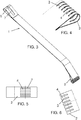
- FIGS. 1 to 6 show different views of a preferred embodiment of the tension band 1 according to the invention and of its parts.
- the tension band 1 comprises an elongated strip of a flat strip material, such. For example, steel of the type S355 or S420, which is folded at the ends to form loops.
- the fastening loop 2 is formed, which is for attachment to the vehicle, for. B. for receiving a retaining bolt 11 (see FIG. 2 , above) is designed.
- the tensioning device in the form of a turnbuckle loop 5, in which a clamping bolt (in the FIGS. 1 to 3 not shown, see clamping bolt 6 in FIG. 7 ) is arranged.
- the fastening loop 2 has six gaps 3, which extend in the longitudinal direction of the tension band 1 and are equally spaced transversely to the longitudinal direction.
- seven tape strips 4 (see FIGS. 4, 5 and 6 ), which surround the retaining bolt 11.
- the length of the column 3 is chosen so that the column 3 over the entire diameter of the holding member 11 (see FIG. 2 , above).
- the tape strips have in the mounting loop 2 the geometry of a comb or the tension elements of an expander.
- a recess 7 is formed in the turnbuckle loop 5, through which the clamping bolt 6 (see FIG. 7 ).
- the turnbuckle loop 5 with the clamping bolt 6 is z. B. as constructed, as it is known from conventional clamping devices.
- the length of the tension band 1 is selected, for example, in the range of 400 mm to 800 mm, while the width of the tension band 1 z. B. 30 mm to 80 mm.
- the width of the column 3 may be selected, for example, in the range of 2 mm to 10 mm.
- the radius of curvature R of the fastening loop 2 is z. B. in the range of 5 mm to 15 mm.
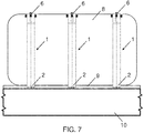
- FIG. 7 schematically shows a part of a motor vehicle 10 with a tank carrier 9, on which a vehicle tank 8 is fixed with a plurality of tension bands 1.
- the first ends of the straps 1 with the fastening loops 2 are fixed to the tank carrier 9, while the second ends of the straps 1 via the clamping bolt 6 to the turnbuckle loops 5 each with other straps (not shown) connected to the top of the vehicle tank 8 are.
- Between the straps 1 and the surface of the vehicle tank 8 are deformable documents, z. B. rubber, (not shown) provided.
- the straps 1 can completely enclose the tank 8 with a suitable length and shape, in which case the turnbuckle loops 5 are coupled via the associated tightening bolts 6 directly to corresponding clamping nuts on the tank support 9.
Landscapes
- Engineering & Computer Science (AREA)
- Mechanical Engineering (AREA)
- Life Sciences & Earth Sciences (AREA)
- Sustainable Development (AREA)
- Sustainable Energy (AREA)
- Chemical & Material Sciences (AREA)
- Combustion & Propulsion (AREA)
- Transportation (AREA)
- General Engineering & Computer Science (AREA)
- Clamps And Clips (AREA)
Abstract
Description
- Die Erfindung betrifft ein Spannband, das zum Beispiel zur Befestigung eines Gegenstands an einem Fahrzeug, insbesondere einem Nutzfahrzeug, ausgelegt ist. Insbesondere betrifft die Erfindung ein Spannband zur Befestigung eines Fahrzeugtanks an einem Tankträger eines Fahrzeugs, vorzugsweise eines Nutzfahrzeugs, wie z. B. eines Lastkraftwagens oder Omnibus.
- Es ist allgemein bekannt, Behälter, wie z. B. Druckluftbehälter oder Fahrzeugtanks, mit Spannbändern an einem passenden Behälterträger zu befestigen (siehe z. B.
DE 197 21 253 A1 oderDE 298 19 881 U1 ). Ein aus der Praxis bekanntes Spannband zur Befestigung eines Fahrzeugtanks an einem Trankträger weist an einem Ende eine aus dem Flachbandmaterial des Spannbandes gebildete Befestigungs-Schlaufe zur Aufnahme eines Haltebolzens des Tankträgers und an einem entgegengesetzten Ende eine Spannschloss-Schlaufe auf, in der ein Spannbolzen zur Verbindung mit dem Fahrzeugträger oder mit dem Spannschloss eines weiteren Spannbandes sitzt. Typischerweise sind mehrere Spannbänder vorgesehen, die den Tank auf dem Tankträger fixieren. - Aufgrund der Biegsamkeit der Spannbänder und der Bereitstellung von deformierbaren Unterlagen zwischen den Spannbändern und der Tankoberfläche ist der Tank im fixierten Zustand relativ zum Tankträger geringfügig beweglich. Daher sind die Spannbänder während des Fahrzeugbetriebs durch Beschleunigungs- und Abbremsvorgänge zahlreichen Lastwechseln ausgesetzt, die sich insbesondere als Schläge auf die Befestigungs-Schlaufen auswirken. Entsprechend kann es an den Befestigungs-Schlaufen zur Rissbildung bis hin zum Funktionsversagen des Spannbandes kommen.
- Aus der Praxis sind Bestrebungen bekannt, der Rissbildung an der Befestigungs-Schlaufe durch die Auswahl besonders widerstandsfähiger Flachbandmaterialien oder die Bereitstellung von Materialverstärkungen im Bereich der Befestigungs-Schlaufe entgegenzuwirken. Daraus ergeben sich jedoch erhöhte Kosten bzw. eine erhöhte Komplexität des Aufbaus eines Spannbandes.
- Die genannten Probleme treten nicht nur bei der Befestigung eines Fahrzeugtanks an einem Fahrzeugträger, sondern generell bei der Befestigung von Gegenständen mit Spannbändern an einem Fahrzeug auf.
- Eine Aufgabe der Erfindung ist es, ein verbessertes Spannband bereitzustellen, mit dem Nachteile herkömmlicher Spannbänder vermieden werden. Das Spannband soll sich insbesondere durch eine verringerte Neigung zur Rissbildung an der Befestigungs-Schlaufe, eine verlängerte Lebensdauer, einen einfachen Aufbau und/oder geringe Kosten auszeichnen.
- Diese Aufgabe kann durch ein Spannband bzw. dessen Verwendung mit den Merkmalen der unabhängigen Ansprüche gelöst werden. Vorteilhafte Weiterbildungen der Erfindung ergeben sich aus den abhängigen Ansprüchen und der folgenden Beschreibung bevorzugter Ausführungsformen der Erfindung.
- Gemäß einem ersten allgemeinen Gesichtspunkt der Erfindung wird zur Lösung der Aufgabe ein Spannband, insbesondere zur Befestigung eines Gegenstands an einem Fahrzeug, vorgeschlagen, wobei an zueinander entgegengesetzten Enden des Spannbandes einerseits eine Befestigungs-Schlaufe, die zur Befestigung des Spannbandes an einem Träger des Gegenstands ausgelegt ist, und andererseits eine Spanneinrichtung vorgesehen sind. Gemäß der Erfindung ist das Flachbandmaterial des Spannbandes an der Befestigungs-Schlaufe durch mehrere Spalte (oder: Schlitze) unterbrochen, die in Zugrichtung des Spannbandes verlaufen. Das Spannband ist an seinem freien Ende, d. h. im Umschlagabschnitt der Befestigungs-Schlaufe in mehrere Bandstreifen (oder: Stege) unterteilt, welche durch die Spalte voneinander getrennt sind.
- Gemäß einem zweiten allgemeinen Gesichtspunkt der Erfindung wird die Verwendung des erfindungsgemäßen Spannbandes zur Befestigung eines Gegenstands an einem Fahrzeug, vorzugsweise zur Befestigung eines Fahrzeugtanks an einem Fahrzeugträger eines Fahrzeugs, insbesondere eines Nutzfahrzeugs, vorgeschlagen.
- Gemäß einem dritten allgemeinen Gesichtspunkt der Erfindung wird ein Kraftfahrzeug mit einem Fahrzeugtank vorgeschlagen, der mit mindestens einem erfindungsgemäßen Spannband an einem Fahrzeugträger befestigt ist.
- Das erfindungsgemäße Spannband hat eine Reihe von Vorteilen, die auf den folgenden Überlegungen des Erfinders beruhen.
- Erstens kann die in mehrere Bandstreifen unterteilte Befestigungs-Schlaufe leichter die Form ändern, als eine Befestigungs-Schlaufe aus einem flächig durchgehenden Flachbandmaterial. Bei Geometrieabweichungen wird eine Vergleichmäßigung der Lastaufteilung erzielt. Das Flachbandmaterial des Spannbandes wird an der Befestigungs-Schlaufe bei einem Lastwechsel lokal weniger stark beansprucht als bei einem herkömmlichen Spannband.
- Zweitens wird im Fall einer Rissbildung lediglich der betroffene Bandstreifen reißen. Der Erfinder hat festgestellt, dass flächig durchgehendes Flachbandmaterial im Bereich der Befestigungs-Schlaufe eines herkömmlichen Spannbandes nach der Bildung eines Risses, z. B. vom Rand des Bandes her oder aus dem Vollmaterial heraus, das Wachstum des Risses durch das Flachbandmaterial begünstigt. Hierzu im Gegensatz wird durch die erfindungsgemäßen Spalte ein Wachstum von Rissen durch das Flachbandmaterial unterbunden.
- Drittens hat der Erfinder festgestellt, dass bei herkömmlichen Spannbändern, die aus kaltgeformtem Stahl hergestellt sind, besonders im Umschlagabschnitt der Befestigungs-Schlaufe innere Spannungen auftreten können, welche bei Lastwechseln die Rissbildung begünstigen. Vorteilhafterweise wird durch die erfindungsgemäß vorgesehenen Spalte, wenn sie vor dem Umformen in das Flachbandmaterial eingebracht worden sind, ein Abbau innerer Spannungen im Flachbandmaterial erreicht.
- Im Ergebnis zeichnet sich das erfindungsgemäße Spannband insbesondere im Umschlagabschnitt der Befestigungs-Schlaufe durch eine erhöhte Verformbarkeit, eine verringerte Rissbildung und verringerte innere Spannungen aus. Es ergeben sich eine erhöhte Lebensdauer des Spannbandes bzw. eine Verzögerung eines Bauteilversagens, ohne dass die Verwendung eines besonders widerstandsfähigen Flachbandmaterials oder eine Verstärkung der Befestigungs-Schlaufe erforderlich sind.
- Die Spalte erstrecken sich in Zugrichtung des Spannbandes, d. h. bei einem geraden Spannband in dessen Längsrichtung. Die Spalte umfassen vorzugsweise gerade, parallele Ausnehmungen im Flachbandmaterial des Spannbandes. Die Befestigungs-Schlaufe ist durch ein Umlegen des Spannbandes in zwei Lagen gebildet, wobei das kurze Ende des Spannbandes zur Bildung der Befestigungs-Schlaufe auf dem langen Ende fixiert, z. B. angeschweißt, ist. Der Umschlagabschnitt der Befestigungs-Schlaufe hat typischerweise eine halbkreisförmige Querschnittsform. Die Spalte werden vorzugsweise mit einem Verfahren, das die Spalte ohne scharfe Kanten oder Grate bildet, z. B. durch Wasserschneiden, Laserbearbeitung o. dgl., hergestellt. Vorteilhafterweise wird damit die Ausbildung einer Kerbwirkung an den Rändern der Bandstreifen vermieden.
- Gemäß einer bevorzugten Ausführungsform ist die Länge der Spalte in Abhängigkeit vom Krümmungsradius R der Befestigungs-Schlaufe, insbesondere des Umschlagabschnitts, zwischen πR und 2πR gewählt. Bei einer Länge πR erstrecken sich die Spalte vorteilhafterweise über den halben Durchmesser eines von der Befestigungs-Schlaufe aufgenommenen Trägerelements, z. B. Haltebolzens, während eine Länge von 2πR eine Erstreckung der Spalte über den gesamten Durchmesser des von der Befestigungs-Schlaufe aufgenommenen Trägerelements ergibt. Der Längenbereich von πR bis 2πR hat den besonderen Vorteil, dass bei geringeren Längen die genannten Wirkungen der Spalte nur eingeschränkt erreicht werden und bei größeren Längen unerwünschte Bewegungen quer zur Zugrichtung des Spannbandes auftreten können.
- Gemäß einer weiteren bevorzugten Ausführungsform der Erfindung weisen die Spalte quer zur Zugrichtung des Spannbandes eine geringere Breite als die Bandstreifen des Flachbandmaterials auf. Vorteilhafterweise werden damit unerwünschte Querbewegungen der Bandstreifen minimiert und eine Beeinträchtigung der Belastbarkeit der Befestigungs-Schlaufe vermieden.
- Wenn gemäß einer weiteren bevorzugten Ausgestaltung der Erfindung die Spalte an ihren Enden in Zugrichtung des Spannbandes abgerundet sind, können sich Vorteile für den Spannungsabbau im Material des Flachbandes und die Vermeidung von Rissen und Kerbwirkungen an den Enden der Bandstreifen ergeben.
- Allgemein umfasst die Befestigungs-Schlaufe des erfindungsgemäßen Spannbandes mindestens zwei Spalte bzw. mindestens drei Bandstreifen, welche durch die mindestens zwei Spalte getrennt sind. Bevorzugt werden Ausführungsformen der Erfindung realisiert, bei denen mindestens drei Spalte, insbesondere mindestens vier Spalte, wie z. B. fünf, sechs oder mehr Spalte vorgesehen sind. Mit der Zahl der Spalte kann die Flexibilität der Befestigungs-Schlaufe vergrößert bzw. die Neigung zur Rissbildung vermindert werden.
- Vorteilhafterweise bestehen keine Einschränkungen hinsichtlich der Gestaltung der Spanneinrichtung am zweiten Ende des Spannbandes. Es kann jeder Typ von Spanneinrichtungen vorgesehen sein, wie sie von herkömmlichen Spannbändern bekannt sind. Vorzugsweise ist als Spanneinrichtung eine Spannschloss-Schlaufe vorgesehen, in der ein Spannbolzen, z. B. ein T-förmiger Spannbolzen oder ein Spannbolzen mit einem Quergewinde zur Aufnahme einer Spannschraube angeordnet ist. Die Bereitstellung der Spannschloss-Schlaufe mit dem Spannbolzen bietet Vorteile aufgrund des einfachen Aufbaus und der Möglichkeit, mehrere erfindungsgemäße Spannbänder miteinander zu kombinieren.
- Beispielsweise kann ein erstes Spannband mit seiner Befestigungs-Schlaufe an einem ersten Haltebolzen des Fahrzeugs, z. B. des Tankträgers, und ein zweites Spannband mit seiner Befestigungs-Schlaufe an einem zweiten Haltebolzen befestigt sein, während die Spanneinrichtungen der ersten und zweiten Spannbänder miteinander verbunden sind und die Spannbänder gemeinsam mit der Trägereinrichtung, z. B. dem Tankträger, den befestigten Gegenstand, z. B. den befestigten Tank, einschließen.
- Gemäß einer weiteren bevorzugten Ausführungsform der Erfindung umfasst das Flachbandmaterial des Spannbandes kaltumgeformten Stahl. Besonders bevorzugt ist das Flachbandmaterial einstückig gebildet, wobei die Befestigungs-Schlaufe und optional die Spannschloss-Schlaufe durch umgelegte Enden des Flachbandmaterials hergestellt sind. Die Erfindung ist jedoch nicht auf die Verwendung von Stahl beschränkt. Vielmehr kann das Flachbandmaterial andere Metalle oder Legierungen, Kunststoff oder Kompositmaterialien umfassen.
- Weitere Einzelheiten und Vorteile der Erfindung werden im Folgenden unter Bezug auf die beigefügten Zeichnungen beschrieben. Es zeigen:
- Figuren 1 bis 3
- eine Draufsicht, eine Seitenansicht und eine Perspektivansicht einer bevorzugten Ausführungsform des erfindungsgemäßen Spannbandes;
- Figur 4:
- eine Perspektivansicht der Befestigungs-Schlaufe des erfindungsgemäßen Spannbandes;
- Figur 5:
- eine Draufsicht auf das Flachbandmaterial des Spannbandes vor Bildung der Befestigungs-Schlaufe;
- Figur 6:
- eine Seitenansicht der Befestigungs-Schlaufe; und
- Figur 7:
- eine schematische Seitenansicht eines mit mehreren Spannbändern befestigten Fahrzeugtanks.
- Merkmale bevorzugter Ausführungsformen der Erfindung werden im Folgenden unter beispielhaftem Bezug auf Spannbänder beschrieben, die zur Befestigung von Fahrzeugtanks an einem Fahrzeugträger eines Kraftfahrzeugs ausgelegt sind. Die Erfindung ist jedoch nicht auf diese Anwendung beschränkt, sondern entsprechend auch bei der Befestigung anderer Lasten an Fahrzeugen, insbesondere Fahrzeugkomponenten, Behälter oder Transportgut, möglich. Das erfindungsgemäße Spannband kann, wie im Folgenden dargestellt, eine gerade Form mit Schlaufen, die relativ zum Spannbandbereich zwischen den Schlaufen abgewinkelt sind, oder alternativ eine gekrümmte, vorzugsweise an die Gestalt des zu haltenden Gegenstandes angepasste Form des Spannbandbereiches zwischen den Schlaufen aufweisen.
- Die
Figuren 1 bis 6 zeigen verschiedene Ansichten einer bevorzugten Ausführungsform des erfindungsgemäßen Spannbandes 1 und von dessen Teilen. Wie in der Draufsicht, der Seitenansicht und der Perspektivansicht derFiguren 1 bis 3 gezeigt, umfasst das Spannband 1 einen langgestreckten Streifen eines Flachbandmaterials, wie z. B. Stahl vom Typ S355 oder S420, das an den Enden zur Bildung von Schlaufen umgelegt ist. An einem ersten Ende des Spannbandes 1 ist die Befestigungs-Schlaufe 2 gebildet, die zur Befestigung am Fahrzeug, z. B. zur Aufnahme eines Haltebolzens 11 (sieheFigur 2 , oben) ausgelegt ist. Am zweiten, entgegengesetzten Ende des Spannbandes 1 befindet sich die Spanneinrichtung in Gestalt einer Spannschloss-Schlaufe 5, in der ein Spannbolzen (in denFiguren 1 bis 3 nicht dargestellt, siehe Spannbolzen 6 inFigur 7 ) angeordnet ist. - Die Befestigungs-Schlaufe 2 weist sechs Spalte 3 auf, die sich in Längsrichtung des Spannbandes 1 erstrecken und quer zur Längsrichtung gleichmäßig beabstandet sind. Entsprechend sind an der Befestigungs-Schlaufe 2 sieben Bandstreifen 4 (siehe
Figuren 4, 5 und 6 ) gebildet, die den Haltebolzen 11 umgreifen. Die Länge der Spalte 3 ist so gewählt, dass die Spalte 3 über den gesamten Durchmesser des Halteelements 11 (sieheFigur 2 , oben) reichen. Die Bandstreifen haben in der Befestigungs-Schlaufe 2 die Geometrie eines Kamms oder der Zugelemente eines Expanders. - Am zweiten Ende des Spannbandes 1 ist in der Spannschloss-Schlaufe 5 eine Ausnehmung 7 gebildet, durch die der Spannbolzen 6 (siehe
Figur 7 ) vorragt. Die Spannschloss-Schlaufe 5 mit dem Spannbolzen 6 ist z. B. so aufgebaut, wie es von herkömmlichen Spanneinrichtungen bekannt ist. - Die Länge des Spannbandes 1 ist beispielsweise im Bereich von 400 mm bis 800 mm gewählt, während die Breite des Spannbandes 1 z. B. 30 mm bis 80 mm beträgt. Die Breite der Spalte 3 kann beispielsweise im Bereich von 2 mm bis 10 mm gewählt sein. Der Krümmungsradius R der Befestigungs-Schlaufe 2 ist z. B. im Bereich von 5 mm bis 15 mm gewählt.
-
Figur 7 zeigt schematisch einen Teil eines Kraftfahrzeugs 10 mit einem Tankträger 9, auf dem ein Fahrzeugtank 8 mit mehreren Spannbändern 1 befestigt ist. Die ersten Enden der Spannbänder 1 mit den Befestigungs-Schlaufen 2 sind am Tankträger 9 fixiert, während die zweiten Enden der Spannbänder 1 über die Spannbolzen 6 an den Spannschloss-Schlaufen 5 jeweils mit weiteren Spannbändern (nicht dargestellt) an der Oberseite des Fahrzeugtanks 8 verbunden sind. Zwischen den Spannbändern 1 und der Oberfläche des Fahrzeugtanks 8 sind deformierbare Unterlagen, z. B. aus Gummi, (nicht dargestellt) vorgesehen. - Alternativ können die Spannbänder 1 bei geeigneter Länge und Form den Tank 8 vollständig umschließen, wobei in diesem Fall die Spannschloss-Schlaufen 5 über die zugehörigen Spannbolzen 6 direkt mit entsprechenden Spannmuttern am Tankträger 9 gekoppelt sind.
- Die Erfindung ist nicht auf die oben beschriebenen Merkmale bevorzugter Ausführungsformen beschränkt. Vielmehr ist eine Vielzahl von Varianten und Abwandlungen möglich, die ebenfalls von dem Erfindungsgedanken Gebrauch machen und deshalb in den Schutzbereich fallen. Darüber hinaus beansprucht die Erfindung auch Schutz für den Gegenstand und die Merkmale der abhängigen Ansprüche unabhängig von den in Bezug genommenen Merkmalen und Ansprüchen.
-
- 1
- Spannband
- 2
- Befestigungs-Schlaufe
- 3
- Spalte
- 4
- Bandstreifen
- 5
- Spannschloss-Schlaufe
- 6
- Spannbolzen
- 7
- Ausnehmung
- 8
- Fahrzeugtank
- 9
- Tankträger
- 10
- Kraftfahrzeug
- 11
- Haltebolzen
Claims (10)
- Spannband (1), insbesondere zur Befestigung eines Gegenstands an einem Fahrzeug (10), umfassend eine Befestigungs-Schlaufe (2), die an einem Ende des Spannbandes (1) durch Flachbandmaterial des Spannbandes (1) gebildet ist und durch mehrere, in Zugrichtung des Spannbandes (1) verlaufende Spalte (3) in Bandstreifen (4) unterteilt ist, und eine Spanneinrichtung, die an einem entgegengesetzten Ende des Spannbandes (1) angeordnet ist.
- Spannband nach Anspruch 1, wobei die Befestigungs-Schlaufe (2) mit einem Krümmungsradius R gebildet ist und die Spalte (3) eine Länge aufweisen, die zwischen πR und 2πR gewählt ist.
- Spannband nach einem der vorhergehenden Ansprüche, wobei die Spalte (3) quer zur Zugrichtung eine geringere Breite als die Bandstreifen (4) aufweisen.
- Spannband nach einem der vorhergehenden Ansprüche, wobei die Spalte (3) in Zugrichtung des Spannbandes (1) im Flachbandmaterial abgerundete Enden aufweisen.
- Spannband nach einem der vorhergehenden Ansprüche, wobei mindestens drei Spalte (3) vorgesehen sind.
- Spannband nach einem der vorhergehenden Ansprüche, wobei die Spanneinrichtung eine Spannschloss-Schlaufe (5) umfasst, die durch das Flachbandmaterial des Spannbandes (1) gebildet ist und in der ein Spannbolzen (6) angeordnet ist.
- Spannband nach einem der vorhergehenden Ansprüche, wobei das Flachbandmaterial kaltumgeformten Stahl umfasst.
- Spannband nach einem der vorhergehenden Ansprüche, das zur Befestigung eines Fahrzeugtanks (8) an einem Tankträger (9) des Kraftfahrzeugs (10) konfiguriert ist.
- Verwendung des Spannbandes (1) nach einem der vorhergehenden Ansprüche zur Befestigung eines Gegenstands an einem Kraftfahrzeug (10), insbesondere eines Fahrzeugtanks (8) an einem Tankträger (9) des Kraftfahrzeugs (10).
- Kraftfahrzeug (10), insbesondere Nutzfahrzeug, das mit einem Tankträger (9) und einem Fahrzeugtank (8) ausgestattet ist, wobei der Fahrzeugtank (8) mit mindestens einem Spannband (1) nach einem vorhergehenden Ansprüche am Tankträger (9) befestigt ist.
Applications Claiming Priority (1)
| Application Number | Priority Date | Filing Date | Title |
|---|---|---|---|
| DE102016015645.7A DE102016015645A1 (de) | 2016-12-30 | 2016-12-30 | Spannband, insbesondere zur Befestigung eines Gegenstands an einem Fahrzeug |
Publications (2)
| Publication Number | Publication Date |
|---|---|
| EP3342618A1 true EP3342618A1 (de) | 2018-07-04 |
| EP3342618B1 EP3342618B1 (de) | 2020-06-17 |
Family
ID=60654818
Family Applications (1)
| Application Number | Title | Priority Date | Filing Date |
|---|---|---|---|
| EP17206335.6A Active EP3342618B1 (de) | 2016-12-30 | 2017-12-11 | Spannband, insbesondere zur befestigung eines gegenstands an einem fahrzeug |
Country Status (2)
| Country | Link |
|---|---|
| EP (1) | EP3342618B1 (de) |
| DE (1) | DE102016015645A1 (de) |
Cited By (1)
| Publication number | Priority date | Publication date | Assignee | Title |
|---|---|---|---|---|
| CN119705709A (zh) * | 2025-01-21 | 2025-03-28 | 广州船舶及海洋工程设计研究院(中国船舶集团有限公司第六〇五研究院) | 一种油箱固定结构 |
Citations (7)
| Publication number | Priority date | Publication date | Assignee | Title |
|---|---|---|---|---|
| US4365393A (en) * | 1981-05-11 | 1982-12-28 | Mueller Co. | Single and multiple section pipe repair clamps |
| DE19721253A1 (de) | 1997-05-21 | 1998-11-26 | Man Nutzfahrzeuge Ag | Spannband für Fahrzeugbehälter |
| DE29819881U1 (de) | 1998-11-06 | 1999-01-21 | Silicon Befestigungstechnik GmbH, 58091 Hagen | Spannband mit T-förmigem Befestigungsbolzen |
| CN204895124U (zh) * | 2015-08-15 | 2015-12-23 | 安徽安凯汽车股份有限公司 | 一种油箱紧固带 |
| CN205292277U (zh) * | 2015-09-29 | 2016-06-08 | 北汽福田汽车股份有限公司 | 气瓶固定装置、气瓶固定装置总成及燃气车辆 |
| WO2018017006A1 (en) * | 2016-07-21 | 2018-01-25 | Scania Cv Ab | A fixation arrangement |
| WO2018030931A1 (en) * | 2016-08-11 | 2018-02-15 | Scania Cv Ab | A fuel tank attaching structure for a motor vehicle |
Family Cites Families (1)
| Publication number | Priority date | Publication date | Assignee | Title |
|---|---|---|---|---|
| DE10230635A1 (de) * | 2002-07-08 | 2004-01-29 | Adam Opel Ag | Befestigungsvorrichtung für Behälter |
-
2016
- 2016-12-30 DE DE102016015645.7A patent/DE102016015645A1/de not_active Withdrawn
-
2017
- 2017-12-11 EP EP17206335.6A patent/EP3342618B1/de active Active
Patent Citations (7)
| Publication number | Priority date | Publication date | Assignee | Title |
|---|---|---|---|---|
| US4365393A (en) * | 1981-05-11 | 1982-12-28 | Mueller Co. | Single and multiple section pipe repair clamps |
| DE19721253A1 (de) | 1997-05-21 | 1998-11-26 | Man Nutzfahrzeuge Ag | Spannband für Fahrzeugbehälter |
| DE29819881U1 (de) | 1998-11-06 | 1999-01-21 | Silicon Befestigungstechnik GmbH, 58091 Hagen | Spannband mit T-förmigem Befestigungsbolzen |
| CN204895124U (zh) * | 2015-08-15 | 2015-12-23 | 安徽安凯汽车股份有限公司 | 一种油箱紧固带 |
| CN205292277U (zh) * | 2015-09-29 | 2016-06-08 | 北汽福田汽车股份有限公司 | 气瓶固定装置、气瓶固定装置总成及燃气车辆 |
| WO2018017006A1 (en) * | 2016-07-21 | 2018-01-25 | Scania Cv Ab | A fixation arrangement |
| WO2018030931A1 (en) * | 2016-08-11 | 2018-02-15 | Scania Cv Ab | A fuel tank attaching structure for a motor vehicle |
Cited By (1)
| Publication number | Priority date | Publication date | Assignee | Title |
|---|---|---|---|---|
| CN119705709A (zh) * | 2025-01-21 | 2025-03-28 | 广州船舶及海洋工程设计研究院(中国船舶集团有限公司第六〇五研究院) | 一种油箱固定结构 |
Also Published As
| Publication number | Publication date |
|---|---|
| EP3342618B1 (de) | 2020-06-17 |
| DE102016015645A1 (de) | 2018-07-05 |
Similar Documents
| Publication | Publication Date | Title |
|---|---|---|
| DE19954647C2 (de) | Seitenaufprallträger | |
| EP3022086B1 (de) | Rückenlehnenstruktur für einen fahrzeugsitz und fahrzeugsitz | |
| EP3245118B1 (de) | Hohlprofil mit sicken | |
| DE202005008665U1 (de) | Elastische Schlaufe, insbesondere zur Aufhängung der Abgasanlage eines Kraftfahrzeugs | |
| DE102013009256A1 (de) | Unterbodenverkleidung für ein Fahrzeug | |
| EP2998158B1 (de) | Lochblechfahrbahn | |
| WO2018138263A1 (de) | Hydrofoil für ein wasserfahrzeug | |
| EP3342618B1 (de) | Spannband, insbesondere zur befestigung eines gegenstands an einem fahrzeug | |
| DE10357927B4 (de) | A-Säule für ein Kraftfahrzeug | |
| DE202015101561U1 (de) | Fangband | |
| EP2420406A1 (de) | Vorrichtung zum Sichern von Ladung auf einer Ladefläche eines Fahrzeugaufbaus | |
| DE202013105503U1 (de) | Flugzeugrumpf | |
| EP2113417B1 (de) | Zurrmittel zur Ladegutsicherung | |
| EP3269592A1 (de) | Gurthakeneinheit | |
| DE102016101531A1 (de) | Umleg-Schnalle | |
| DE202014003055U1 (de) | Schiene zur Sicherung von Ladung | |
| DE202018005759U1 (de) | Frachttransportsystem mit einem Sandwich-Paneel und einem Kanal | |
| EP2474409B1 (de) | Stoffschlüssige Verbindung zwischen einem Basisbauteil und einem mehrschichtigen Faserverbundbauteil | |
| DE102008025440B4 (de) | Einstecklatte für einen Aufbau eines Transportfahrzeugs, Aufbau für die Ladefläche eines Transportfahrzeugs, eines Lastkraftwagens, eines Aufliegers oder Anhängers für einen Lastkraftwagen mit einer solchen Einstecklatte und Transportfahrzeug, Lastkraftwagen, Auflieger oder Anhänger für einen Lastkraftwagen mit einer Ladefläche und einem solchen Aufbau. | |
| EP3251998B1 (de) | Auslegerprofil für den ausleger eines teleskopkrans | |
| AT517922B1 (de) | Bremsbelagträgerplatte | |
| DE10322569A1 (de) | Verzurrhalterung zur Anbringung an einem Träger | |
| DE2804735C3 (de) | Endbeschlag für Lasthebe- und/oder Verzurrbänder | |
| EP2428397A1 (de) | Lochprofilschiene | |
| DE102016206587B4 (de) | Hydraulische Steuerung, umfassend eine Ventilbohrung sowie eine Halteklammer zur Befestigung eines Stopfens in der Ventilbohrung |
Legal Events
| Date | Code | Title | Description |
|---|---|---|---|
| PUAI | Public reference made under article 153(3) epc to a published international application that has entered the european phase |
Free format text: ORIGINAL CODE: 0009012 |
|
| STAA | Information on the status of an ep patent application or granted ep patent |
Free format text: STATUS: THE APPLICATION HAS BEEN PUBLISHED |
|
| AK | Designated contracting states |
Kind code of ref document: A1 Designated state(s): AL AT BE BG CH CY CZ DE DK EE ES FI FR GB GR HR HU IE IS IT LI LT LU LV MC MK MT NL NO PL PT RO RS SE SI SK SM TR |
|
| AX | Request for extension of the european patent |
Extension state: BA ME |
|
| STAA | Information on the status of an ep patent application or granted ep patent |
Free format text: STATUS: REQUEST FOR EXAMINATION WAS MADE |
|
| 17P | Request for examination filed |
Effective date: 20190103 |
|
| RBV | Designated contracting states (corrected) |
Designated state(s): AL AT BE BG CH CY CZ DE DK EE ES FI FR GB GR HR HU IE IS IT LI LT LU LV MC MK MT NL NO PL PT RO RS SE SI SK SM TR |
|
| STAA | Information on the status of an ep patent application or granted ep patent |
Free format text: STATUS: EXAMINATION IS IN PROGRESS |
|
| RAP1 | Party data changed (applicant data changed or rights of an application transferred) |
Owner name: MAN TRUCK & BUS SE |
|
| 17Q | First examination report despatched |
Effective date: 20190705 |
|
| GRAP | Despatch of communication of intention to grant a patent |
Free format text: ORIGINAL CODE: EPIDOSNIGR1 |
|
| STAA | Information on the status of an ep patent application or granted ep patent |
Free format text: STATUS: GRANT OF PATENT IS INTENDED |
|
| INTG | Intention to grant announced |
Effective date: 20200115 |
|
| GRAJ | Information related to disapproval of communication of intention to grant by the applicant or resumption of examination proceedings by the epo deleted |
Free format text: ORIGINAL CODE: EPIDOSDIGR1 |
|
| GRAL | Information related to payment of fee for publishing/printing deleted |
Free format text: ORIGINAL CODE: EPIDOSDIGR3 |
|
| GRAS | Grant fee paid |
Free format text: ORIGINAL CODE: EPIDOSNIGR3 |
|
| STAA | Information on the status of an ep patent application or granted ep patent |
Free format text: STATUS: EXAMINATION IS IN PROGRESS |
|
| GRAR | Information related to intention to grant a patent recorded |
Free format text: ORIGINAL CODE: EPIDOSNIGR71 |
|
| STAA | Information on the status of an ep patent application or granted ep patent |
Free format text: STATUS: GRANT OF PATENT IS INTENDED |
|
| GRAA | (expected) grant |
Free format text: ORIGINAL CODE: 0009210 |
|
| STAA | Information on the status of an ep patent application or granted ep patent |
Free format text: STATUS: THE PATENT HAS BEEN GRANTED |
|
| INTC | Intention to grant announced (deleted) | ||
| AK | Designated contracting states |
Kind code of ref document: B1 Designated state(s): AL AT BE BG CH CY CZ DE DK EE ES FI FR GB GR HR HU IE IS IT LI LT LU LV MC MK MT NL NO PL PT RO RS SE SI SK SM TR |
|
| INTG | Intention to grant announced |
Effective date: 20200511 |
|
| REG | Reference to a national code |
Ref country code: GB Ref legal event code: FG4D Free format text: NOT ENGLISH |
|
| REG | Reference to a national code |
Ref country code: CH Ref legal event code: EP |
|
| REG | Reference to a national code |
Ref country code: IE Ref legal event code: FG4D Free format text: LANGUAGE OF EP DOCUMENT: GERMAN |
|
| REG | Reference to a national code |
Ref country code: DE Ref legal event code: R096 Ref document number: 502017005729 Country of ref document: DE |
|
| REG | Reference to a national code |
Ref country code: AT Ref legal event code: REF Ref document number: 1280891 Country of ref document: AT Kind code of ref document: T Effective date: 20200715 |
|
| REG | Reference to a national code |
Ref country code: NL Ref legal event code: FP |
|
| REG | Reference to a national code |
Ref country code: SE Ref legal event code: TRGR |
|
| PG25 | Lapsed in a contracting state [announced via postgrant information from national office to epo] |
Ref country code: NO Free format text: LAPSE BECAUSE OF FAILURE TO SUBMIT A TRANSLATION OF THE DESCRIPTION OR TO PAY THE FEE WITHIN THE PRESCRIBED TIME-LIMIT Effective date: 20200917 Ref country code: GR Free format text: LAPSE BECAUSE OF FAILURE TO SUBMIT A TRANSLATION OF THE DESCRIPTION OR TO PAY THE FEE WITHIN THE PRESCRIBED TIME-LIMIT Effective date: 20200918 Ref country code: FI Free format text: LAPSE BECAUSE OF FAILURE TO SUBMIT A TRANSLATION OF THE DESCRIPTION OR TO PAY THE FEE WITHIN THE PRESCRIBED TIME-LIMIT Effective date: 20200617 Ref country code: LT Free format text: LAPSE BECAUSE OF FAILURE TO SUBMIT A TRANSLATION OF THE DESCRIPTION OR TO PAY THE FEE WITHIN THE PRESCRIBED TIME-LIMIT Effective date: 20200617 |
|
| REG | Reference to a national code |
Ref country code: LT Ref legal event code: MG4D |
|
| PG25 | Lapsed in a contracting state [announced via postgrant information from national office to epo] |
Ref country code: LV Free format text: LAPSE BECAUSE OF FAILURE TO SUBMIT A TRANSLATION OF THE DESCRIPTION OR TO PAY THE FEE WITHIN THE PRESCRIBED TIME-LIMIT Effective date: 20200617 Ref country code: BG Free format text: LAPSE BECAUSE OF FAILURE TO SUBMIT A TRANSLATION OF THE DESCRIPTION OR TO PAY THE FEE WITHIN THE PRESCRIBED TIME-LIMIT Effective date: 20200917 Ref country code: RS Free format text: LAPSE BECAUSE OF FAILURE TO SUBMIT A TRANSLATION OF THE DESCRIPTION OR TO PAY THE FEE WITHIN THE PRESCRIBED TIME-LIMIT Effective date: 20200617 Ref country code: HR Free format text: LAPSE BECAUSE OF FAILURE TO SUBMIT A TRANSLATION OF THE DESCRIPTION OR TO PAY THE FEE WITHIN THE PRESCRIBED TIME-LIMIT Effective date: 20200617 |
|
| PG25 | Lapsed in a contracting state [announced via postgrant information from national office to epo] |
Ref country code: AL Free format text: LAPSE BECAUSE OF FAILURE TO SUBMIT A TRANSLATION OF THE DESCRIPTION OR TO PAY THE FEE WITHIN THE PRESCRIBED TIME-LIMIT Effective date: 20200617 |
|
| PG25 | Lapsed in a contracting state [announced via postgrant information from national office to epo] |
Ref country code: SM Free format text: LAPSE BECAUSE OF FAILURE TO SUBMIT A TRANSLATION OF THE DESCRIPTION OR TO PAY THE FEE WITHIN THE PRESCRIBED TIME-LIMIT Effective date: 20200617 Ref country code: EE Free format text: LAPSE BECAUSE OF FAILURE TO SUBMIT A TRANSLATION OF THE DESCRIPTION OR TO PAY THE FEE WITHIN THE PRESCRIBED TIME-LIMIT Effective date: 20200617 Ref country code: RO Free format text: LAPSE BECAUSE OF FAILURE TO SUBMIT A TRANSLATION OF THE DESCRIPTION OR TO PAY THE FEE WITHIN THE PRESCRIBED TIME-LIMIT Effective date: 20200617 Ref country code: CZ Free format text: LAPSE BECAUSE OF FAILURE TO SUBMIT A TRANSLATION OF THE DESCRIPTION OR TO PAY THE FEE WITHIN THE PRESCRIBED TIME-LIMIT Effective date: 20200617 Ref country code: ES Free format text: LAPSE BECAUSE OF FAILURE TO SUBMIT A TRANSLATION OF THE DESCRIPTION OR TO PAY THE FEE WITHIN THE PRESCRIBED TIME-LIMIT Effective date: 20200617 Ref country code: PT Free format text: LAPSE BECAUSE OF FAILURE TO SUBMIT A TRANSLATION OF THE DESCRIPTION OR TO PAY THE FEE WITHIN THE PRESCRIBED TIME-LIMIT Effective date: 20201019 |
|
| PG25 | Lapsed in a contracting state [announced via postgrant information from national office to epo] |
Ref country code: IS Free format text: LAPSE BECAUSE OF FAILURE TO SUBMIT A TRANSLATION OF THE DESCRIPTION OR TO PAY THE FEE WITHIN THE PRESCRIBED TIME-LIMIT Effective date: 20201017 Ref country code: PL Free format text: LAPSE BECAUSE OF FAILURE TO SUBMIT A TRANSLATION OF THE DESCRIPTION OR TO PAY THE FEE WITHIN THE PRESCRIBED TIME-LIMIT Effective date: 20200617 Ref country code: SK Free format text: LAPSE BECAUSE OF FAILURE TO SUBMIT A TRANSLATION OF THE DESCRIPTION OR TO PAY THE FEE WITHIN THE PRESCRIBED TIME-LIMIT Effective date: 20200617 |
|
| REG | Reference to a national code |
Ref country code: DE Ref legal event code: R097 Ref document number: 502017005729 Country of ref document: DE |
|
| PLBE | No opposition filed within time limit |
Free format text: ORIGINAL CODE: 0009261 |
|
| STAA | Information on the status of an ep patent application or granted ep patent |
Free format text: STATUS: NO OPPOSITION FILED WITHIN TIME LIMIT |
|
| PG25 | Lapsed in a contracting state [announced via postgrant information from national office to epo] |
Ref country code: DK Free format text: LAPSE BECAUSE OF FAILURE TO SUBMIT A TRANSLATION OF THE DESCRIPTION OR TO PAY THE FEE WITHIN THE PRESCRIBED TIME-LIMIT Effective date: 20200617 |
|
| 26N | No opposition filed |
Effective date: 20210318 |
|
| PG25 | Lapsed in a contracting state [announced via postgrant information from national office to epo] |
Ref country code: SI Free format text: LAPSE BECAUSE OF FAILURE TO SUBMIT A TRANSLATION OF THE DESCRIPTION OR TO PAY THE FEE WITHIN THE PRESCRIBED TIME-LIMIT Effective date: 20200617 |
|
| REG | Reference to a national code |
Ref country code: CH Ref legal event code: PL |
|
| PG25 | Lapsed in a contracting state [announced via postgrant information from national office to epo] |
Ref country code: MC Free format text: LAPSE BECAUSE OF FAILURE TO SUBMIT A TRANSLATION OF THE DESCRIPTION OR TO PAY THE FEE WITHIN THE PRESCRIBED TIME-LIMIT Effective date: 20200617 |
|
| REG | Reference to a national code |
Ref country code: BE Ref legal event code: MM Effective date: 20201231 |
|
| PG25 | Lapsed in a contracting state [announced via postgrant information from national office to epo] |
Ref country code: LU Free format text: LAPSE BECAUSE OF NON-PAYMENT OF DUE FEES Effective date: 20201211 Ref country code: IE Free format text: LAPSE BECAUSE OF NON-PAYMENT OF DUE FEES Effective date: 20201211 |
|
| PG25 | Lapsed in a contracting state [announced via postgrant information from national office to epo] |
Ref country code: CH Free format text: LAPSE BECAUSE OF NON-PAYMENT OF DUE FEES Effective date: 20201231 Ref country code: LI Free format text: LAPSE BECAUSE OF NON-PAYMENT OF DUE FEES Effective date: 20201231 |
|
| PG25 | Lapsed in a contracting state [announced via postgrant information from national office to epo] |
Ref country code: TR Free format text: LAPSE BECAUSE OF FAILURE TO SUBMIT A TRANSLATION OF THE DESCRIPTION OR TO PAY THE FEE WITHIN THE PRESCRIBED TIME-LIMIT Effective date: 20200617 Ref country code: MT Free format text: LAPSE BECAUSE OF FAILURE TO SUBMIT A TRANSLATION OF THE DESCRIPTION OR TO PAY THE FEE WITHIN THE PRESCRIBED TIME-LIMIT Effective date: 20200617 Ref country code: CY Free format text: LAPSE BECAUSE OF FAILURE TO SUBMIT A TRANSLATION OF THE DESCRIPTION OR TO PAY THE FEE WITHIN THE PRESCRIBED TIME-LIMIT Effective date: 20200617 |
|
| PG25 | Lapsed in a contracting state [announced via postgrant information from national office to epo] |
Ref country code: MK Free format text: LAPSE BECAUSE OF FAILURE TO SUBMIT A TRANSLATION OF THE DESCRIPTION OR TO PAY THE FEE WITHIN THE PRESCRIBED TIME-LIMIT Effective date: 20200617 |
|
| PG25 | Lapsed in a contracting state [announced via postgrant information from national office to epo] |
Ref country code: BE Free format text: LAPSE BECAUSE OF NON-PAYMENT OF DUE FEES Effective date: 20201231 |
|
| GBPC | Gb: european patent ceased through non-payment of renewal fee |
Effective date: 20211211 |
|
| PG25 | Lapsed in a contracting state [announced via postgrant information from national office to epo] |
Ref country code: GB Free format text: LAPSE BECAUSE OF NON-PAYMENT OF DUE FEES Effective date: 20211211 |
|
| REG | Reference to a national code |
Ref country code: AT Ref legal event code: MM01 Ref document number: 1280891 Country of ref document: AT Kind code of ref document: T Effective date: 20221211 |
|
| PG25 | Lapsed in a contracting state [announced via postgrant information from national office to epo] |
Ref country code: AT Free format text: LAPSE BECAUSE OF NON-PAYMENT OF DUE FEES Effective date: 20221211 |
|
| PG25 | Lapsed in a contracting state [announced via postgrant information from national office to epo] |
Ref country code: AT Free format text: LAPSE BECAUSE OF NON-PAYMENT OF DUE FEES Effective date: 20221211 |
|
| PGFP | Annual fee paid to national office [announced via postgrant information from national office to epo] |
Ref country code: IT Payment date: 20251218 Year of fee payment: 9 |
|
| PGFP | Annual fee paid to national office [announced via postgrant information from national office to epo] |
Ref country code: NL Payment date: 20251222 Year of fee payment: 9 Ref country code: FR Payment date: 20251230 Year of fee payment: 9 |
|
| PGFP | Annual fee paid to national office [announced via postgrant information from national office to epo] |
Ref country code: SE Payment date: 20251222 Year of fee payment: 9 |
|
| PGFP | Annual fee paid to national office [announced via postgrant information from national office to epo] |
Ref country code: DE Payment date: 20251229 Year of fee payment: 9 |
|
| PGFP | Annual fee paid to national office [announced via postgrant information from national office to epo] |
Ref country code: AT Payment date: 20260410 Year of fee payment: 5 |