EP3341258B1 - Ortungssystem und -verfahren für auf führungsbahn montiertes fahrzeug - Google Patents
Ortungssystem und -verfahren für auf führungsbahn montiertes fahrzeug Download PDFInfo
- Publication number
- EP3341258B1 EP3341258B1 EP16838653.0A EP16838653A EP3341258B1 EP 3341258 B1 EP3341258 B1 EP 3341258B1 EP 16838653 A EP16838653 A EP 16838653A EP 3341258 B1 EP3341258 B1 EP 3341258B1
- Authority
- EP
- European Patent Office
- Prior art keywords
- sensor
- vehicle
- markers
- sensors
- marker
- Prior art date
- Legal status (The legal status is an assumption and is not a legal conclusion. Google has not performed a legal analysis and makes no representation as to the accuracy of the status listed.)
- Active
Links
- 238000000034 method Methods 0.000 title claims description 35
- 230000004807 localization Effects 0.000 title description 7
- 239000003550 marker Substances 0.000 claims description 146
- 238000001514 detection method Methods 0.000 claims description 26
- 230000004927 fusion Effects 0.000 description 39
- 238000004364 calculation method Methods 0.000 description 11
- 230000003287 optical effect Effects 0.000 description 9
- 238000012935 Averaging Methods 0.000 description 6
- 238000010586 diagram Methods 0.000 description 6
- 238000004891 communication Methods 0.000 description 5
- 238000012545 processing Methods 0.000 description 4
- 238000000926 separation method Methods 0.000 description 4
- 238000013459 approach Methods 0.000 description 3
- 238000004590 computer program Methods 0.000 description 3
- 230000010354 integration Effects 0.000 description 2
- 239000004065 semiconductor Substances 0.000 description 2
- 230000001133 acceleration Effects 0.000 description 1
- 230000007423 decrease Effects 0.000 description 1
- 230000001934 delay Effects 0.000 description 1
- 230000005670 electromagnetic radiation Effects 0.000 description 1
- 230000006870 function Effects 0.000 description 1
- 238000003384 imaging method Methods 0.000 description 1
- 238000002329 infrared spectrum Methods 0.000 description 1
- 238000012423 maintenance Methods 0.000 description 1
- 238000004519 manufacturing process Methods 0.000 description 1
- 238000002044 microwave spectrum Methods 0.000 description 1
- 230000000630 rising effect Effects 0.000 description 1
- 238000012163 sequencing technique Methods 0.000 description 1
- 230000011664 signaling Effects 0.000 description 1
- 230000003068 static effect Effects 0.000 description 1
- 238000006467 substitution reaction Methods 0.000 description 1
- 238000001429 visible spectrum Methods 0.000 description 1
Images


Classifications
-
- B—PERFORMING OPERATIONS; TRANSPORTING
- B61—RAILWAYS
- B61L—GUIDING RAILWAY TRAFFIC; ENSURING THE SAFETY OF RAILWAY TRAFFIC
- B61L25/00—Recording or indicating positions or identities of vehicles or trains or setting of track apparatus
- B61L25/02—Indicating or recording positions or identities of vehicles or trains
- B61L25/026—Relative localisation, e.g. using odometer
-
- B—PERFORMING OPERATIONS; TRANSPORTING
- B61—RAILWAYS
- B61L—GUIDING RAILWAY TRAFFIC; ENSURING THE SAFETY OF RAILWAY TRAFFIC
- B61L25/00—Recording or indicating positions or identities of vehicles or trains or setting of track apparatus
- B61L25/02—Indicating or recording positions or identities of vehicles or trains
- B61L25/025—Absolute localisation, e.g. providing geodetic coordinates
-
- B—PERFORMING OPERATIONS; TRANSPORTING
- B61—RAILWAYS
- B61L—GUIDING RAILWAY TRAFFIC; ENSURING THE SAFETY OF RAILWAY TRAFFIC
- B61L25/00—Recording or indicating positions or identities of vehicles or trains or setting of track apparatus
- B61L25/02—Indicating or recording positions or identities of vehicles or trains
- B61L25/021—Measuring and recording of train speed
-
- B—PERFORMING OPERATIONS; TRANSPORTING
- B61—RAILWAYS
- B61L—GUIDING RAILWAY TRAFFIC; ENSURING THE SAFETY OF RAILWAY TRAFFIC
- B61L27/00—Central railway traffic control systems; Trackside control; Communication systems specially adapted therefor
- B61L27/20—Trackside control of safe travel of vehicle or train, e.g. braking curve calculation
- B61L2027/204—Trackside control of safe travel of vehicle or train, e.g. braking curve calculation using Communication-based Train Control [CBTC]
-
- B—PERFORMING OPERATIONS; TRANSPORTING
- B61—RAILWAYS
- B61L—GUIDING RAILWAY TRAFFIC; ENSURING THE SAFETY OF RAILWAY TRAFFIC
- B61L27/00—Central railway traffic control systems; Trackside control; Communication systems specially adapted therefor
- B61L27/20—Trackside control of safe travel of vehicle or train, e.g. braking curve calculation
Definitions
- Guideway mounted vehicles include communication train based control (CTBC) systems to receive movement instructions from wayside mounted devices adjacent to a guideway.
- CTBC systems are used to determine a location and a speed of the guideway mounted vehicle.
- the CTBC systems determine the location and speed by interrogating transponders positioned along the guideway.
- the CTBC systems report the determined location and speed to a centralized control system or to a de-centralized control system through the wayside mounted devices.
- the centralized or de-centralized control system stores the location and speed information for guideway mounted vehicles within a control zone. Based on this stored location and speed information, the centralized or de-centralized control system generates movement instructions for the guideway mounted vehicles.
- WO2014/177954 A1 discloses a vehicle position determining system. It comprises plural sensors spaced from each other in a direction of travel along a guideway of the vehicle. The spacing is used to identify a precise location of a position element.
- the invention relates to a system according to claim 1 and to a method according to claim 16.
- the following disclosure provides many different embodiments, or examples, for implementing different features of the invention. Specific examples of components and arrangements are described below to simplify the present disclosure. These are examples and are not intended to be limiting.
- FIG. 1 is a diagram of a vehicle localization system 100, in accordance with one or more embodiments.
- Vehicle localization system 100 is associated with a vehicle 102 having a first end 104 and a second end 106.
- Vehicle localization system 100 comprises a controller 108, a memory 109, a first set of sensors including a first sensor 110a, a second sensor 110b (collectively referred to herein as the "first set of sensors 110") on the first end 104 of the vehicle 102, and a second set of sensors including a third sensor 112a and a fourth sensor 112b (collectively referred to herein as the "second set of sensors 112") on the second end 106 of the vehicle.
- first set of sensors including a first sensor 110a, a second sensor 110b (collectively referred to herein as the "first set of sensors 110") on the first end 104 of the vehicle 102
- second set of sensors including a third sensor 112a and a fourth sensor 112b (collectively referred to herein
- the first set of sensors 110 optionally includes a first auxiliary sensor 110c.
- the second set of sensors 112 optionally includes a second auxiliary sensor 112c.
- one or more of the first set of sensors 110 or the second set of sensors 112 includes only one sensor.
- the controller 108 is communicatively coupled with the memory 109, the sensors of the first set of sensors 110 and with the sensors of the second set of sensors 112.
- the controller 108 is on-board the vehicle 102. If on-board, the controller 108 is a vehicle on-board controller ("VOBC"). In some embodiments, one or more of the controller 108 or the memory 109 is off-board the vehicle 102. In some embodiments, the controller 108 comprises one or more of the memory 109 and a processor (e.g., processor 902 (shown in FIG. 9 )).
- Vehicle 102 is configured to move along a guideway 114 in one of a first direction 116 or a second direction 118.
- guideway 114 includes two spaced rails.
- guideway 114 includes a monorail.
- guideway 114 is along a ground.
- guideway 114 is elevated above the ground. Based on which direction the vehicle 102 moves along the guideway 114, one of the first end 104 is a leading end of the vehicle 102 or the second end 106 is the leading end of the vehicle 102. The leading end of the vehicle 102 is the end of the vehicle 102 that corresponds to the direction of movement of the vehicle 102 along the guideway 114.
- the vehicle 102 moves in the first direction 116, then the first end 104 is the leading end of the vehicle 102. If the vehicle 102 moves in the second direction 118, then the second end 106 is the leading end of the vehicle 102.
- the vehicle 102 is capable of being rotated with respect to the guideway 114 such that the first end 104 is the leading end of the vehicle 102 if the vehicle 102 moves in the second direction 118, and the second end 106 is the leading end of the vehicle 102 if the vehicle 102 moves in the first direction 116.
- the sensors of the first set of sensors 110 and the sensors of the second set of sensors 112 are each configured to detect markers of a plurality of markers 120a-120n, where n is a positive integer greater than 1,.
- the markers of the plurality of markers 120a-120n are collectively referred to herein as "marker(s) 120.”
- the sensors of the first set of sensors 110 and the sensor of the second set of sensors 112 are each configured to generate corresponding sensor data based on a detected marker 120.
- a marker 120 is, for example, a static object such as a sign, a shape, a pattern of objects, a distinct or sharp change in one or more guideway properties (e.g. direction, curvature, or other identifiable property) which can be accurately associated with a specific location, or some other suitable detectable feature or object usable to determine a geographic location of a vehicle.
- One or more of the markers 120 are on the guideway 114. In some embodiments, one or more of the markers 120 are on a wayside of the guideway 114. In some embodiments, all of the markers 120 are on the guideway. In some embodiments, all of the markers 120 are on the wayside of the guideway.
- the markers 120 comprise one or more of rails installed on the guideway 114, sleepers or ties installed on the guideway 114, rail baseplates installed on the guideway 114, garbage catchers installed on the guideway 114, boxes containing signaling equipment installed on the guideway 114, fence posts installed on the wayside of the guideway 114, signs installed on the wayside of the guideway 114, other suitable objects associated with being on the guideway 114 or on the wayside of the guideway 114.
- at least some of the markers 120 comprise one or more different objects or patterns of objects compared to other markers 120. For example, if one marker 120 comprises a garbage catcher, a different marker 120 comprises a railroad tie.
- Consecutive markers 120 are spaced apart by a distance d.
- the distance d between consecutive markers 120 is substantially equal between all of the markers 120 of the plurality of markers 120a-120n. In some embodiments, the distance d between consecutive markers 120 is different between a first pair of markers 120 and a second pair of markers 120.
- the memory 109 comprises data that includes information describing the markers 120 and a geographic position of the markers 120. Based on the detection of a marker 120, controller 108 is configured to query the memory 109 for the information describing the detected marker 120 such that the detected marker 120 has a location that is known to the controller 108.
- Each of the sensors of the first set of sensors 110 and the sensors of the second set of sensors 112 is positioned on the first end 104 of the vehicle 102 or the second end of the vehicle 102 at a corresponding distance L from the markers 120.
- the distance L is measured in a direction perpendicular to the direction of movement of the vehicle 102, between each sensor of the first set of sensors 110 and each sensor of the second set of sensors 112 as the vehicle 102 moves past a same marker 120. For example, if the vehicle 102 is moving in the first direction 116, the first sensor 110a is positioned a distance L1 from marker 120a, and second sensor 110b is positioned a distance L2 from marker 120a.
- third sensor 112a is a distance L3 from marker 120a
- fourth sensor 112b is a distance L4 from marker 120a.
- the corresponding distances L1, L2, L3 and L4 are not shown in Figure 1 to avoid obscuring the drawing.
- the first sensor 110a has a first inclination angle ⁇ 1 with respect to the detected marker 120.
- the second sensor 110b has a second inclination angle ⁇ 2 with respect to the detected marker 120 different from the first inclination angle ⁇ 1.
- the third sensor 112a has a third inclination angle ⁇ 1 with respect to the detected marker 120.
- the fourth sensor 112b has a fourth inclination angle ⁇ 2 with respect to the detected marker 120 of different from the fourth inclination angle ⁇ 1.
- the discussed inclination angles ⁇ 1, ⁇ 2, ⁇ 1 and ⁇ 2 are measured with respect to a corresponding horizon line that is parallel to the guideway 114.
- the corresponding horizon line for each sensor of the first set of sensors 110 and each sensor of the second set of sensors 112 is separated from the marker 120 by the corresponding distance L of each sensor of the first set of sensors 110 or each sensor of the second set of sensors 112.
- inclination angle ⁇ 1 is substantially equal to inclination angle ⁇ 1
- inclination angle ⁇ 2 is substantially equal to inclination angle ⁇ 2.
- Each of the sensors of the first set of sensors 110 and the sensors of the second set of sensors 112 has a corresponding field of view.
- Sensor 110a has a field of view 122a that is based on the position of sensor 110a on the first end 104 of the vehicle 102 and inclination angle ⁇ 1.
- Sensor 110b has a field of view 122b that is based on the position of sensor 110b on the first end 104 of the vehicle 102 and inclination angle ⁇ 2.
- Sensor 112a has a field of view 124a that is based on the position of sensor 112a on the second end 106 of the vehicle 102 and inclination angle ⁇ 1.
- Sensor 112b has a field of view 124b that is based on the position of sensor 112b on the second end 106 of the vehicle 102 and inclination angle ⁇ 2.
- Field of view 122a overlaps with field of view 122b
- field of view 124a overlaps with field of view 124b.
- one or more of field of view 122a and field of view 122b are non-overlapping, or field of view 124a and field of view 124b are non-overlapping.
- the position and inclination angle of each sensor 110 of the first set of sensors 110 is such that a detected marker 120 enters one of the field of view 122a or 122b, first, based on the direction the vehicle 102 moves along the guideway 114.
- each sensor 112 of the second set of sensors 112 is such that a detected marker 120 enters one of the field of view 124a or 124b, first, based on the direction the vehicle 102 moves along the guideway 114.
- the markers 120 are spaced along the guideway 114 such that only one of the markers 120 is within field of view 122a or 122b at a time.
- the markers 120 are spaced along the guideway 114 such that only one of the markers 120 is within field of view 124a or 124b at a time.
- the markers 120 are spaced along the guideway 114 such that only one of the markers 120 is within field of view 122a, 122b, 124a or 124b at a time. In some embodiments, markers 120 are spaced along the guideway 114 such that only one marker 120 is detected by the sensors of the first set of sensors 110 or the sensors of the second set of sensors 112 at a time. That is, in some embodiments, a marker 120 is within field of view 122a and 122b, or within field of view 124a and 124b.
- the markers 120 are separated by a distance d that results in there being non-detection time between consecutive marker 120 detections as the vehicle 102 moves along the guideway 114.
- the markers 120 are separated by a distance d that results in there being a non-detection time to a detection time ratio that is at least about 0.40. In some embodiments, the ratio of non-detection time to detection time is at least about 0.50.
- the distance d between consecutive markers 120 is such that a ratio of a detection span I of the sensors (e.g., the first set of sensors 110 and the second set of sensors 112) to the distance d between consecutive markers 120 is less than about 0.50.
- a ratio of a detection span I of the sensors e.g., the first set of sensors 110 and the second set of sensors 112
- markers 120 that have a distinct difference between consecutive markers 120 makes it possible to reduce the distance d between consecutive markers 120 compared to other embodiments in which the markers 120 are separated by a distance d that is greater than about twice the detection span I, or embodiments in which the ratio of non-detection time to detection time being greater than about 0.50, for example.
- the distance d between consecutive markers 120 is set based on one or more of the velocity of the vehicle 102, processing time and delays of the controller 108, field of view 122a, 122b, 124a and/or 124b, the inclination angles ⁇ 1, ⁇ 2, ⁇ 1, and/or ⁇ 2, the separation distances L1, L2, L3 and/or L4 between the sensors and the markers 120, and/or a width of each marker 120 measured in the direction of movement of the vehicle 102.
- Sensors of the first set of sensors 110 and sensors of the second set of sensors 112 are one or more of radio detection and ranging (“RADAR”) sensors, laser imaging detection and ranging (“LIDAR”) sensors, cameras, infrared-based sensors, or other suitable sensors configured to detect an object or pattern of objects such as markers 120.
- RADAR radio detection and ranging
- LIDAR laser imaging detection and ranging
- sensors of the second set of sensors 112 are one or more of radio detection and ranging (“RADAR”) sensors, laser imaging detection and ranging (“LIDAR”) sensors, cameras, infrared-based sensors, or other suitable sensors configured to detect an object or pattern of objects such as markers 120.
- the controller 108 is configured to determine which of the first end 104 or the second end 106 of the vehicle 102 is the leading end of the vehicle 102 as the vehicle 102 moves along the guideway 114, determine a position of the leading end of the vehicle 102 with respect to a detected marker 120, determine a position of the vehicle 102 with respect to a detected marker 120, and determine a velocity of the vehicle 102 as the vehicle 102 moves along the guideway 114.
- the controller 108 is configured to use one or more of the sensor data generated by the first sensor 110a or the second sensor 110b of the first set of sensors 110 as the sensor data for determining the leading end of the vehicle 102, the position of the leading end of the vehicle 102, the velocity of the vehicle 102, the velocity of the leading end of the vehicle 102, the position of the other end of the vehicle 102, and/or the velocity of the other end of the vehicle 102.
- the controller 108 is configured to use one or more of the sensor data generated by the third sensor 112a or the fourth sensor 112b of the second set of sensors 112 as the sensor data for determining the leading end of the vehicle 102, the position of the leading end of the vehicle 102, the velocity of the vehicle 102, the velocity of the leading end of the vehicle 102, the position of the other end of the vehicle 102, and/or the velocity of the other end of the vehicle 102.
- the controller 108 is configured to fuse sensor data generated by different sensors of the first set of sensors 110 and/or the second set of sensors 112 by averaging, comparing, and/or weighting sensor data that is collected by the sensors of the first set of sensors 110 and/or the sensors of the second set of sensors 112 to generate fused sensor data.
- the controller 108 is then configured to use the fused sensor data as the sensor data for determining the leading end of the vehicle 102, calculating the distance the vehicle traveled, and/or the velocity of the vehicle 102.
- the controller 108 is configured to calculate the distance traveled from a first marker 120 based on a fusion of the sensor data generated by the first set of sensors 110 or the second set of sensors 112.
- the controller 108 is configured to calculate the distance traveled from a first marker 120 based on a fusion of the sensor data generated by the first set of sensors 110 and the second set of sensors 112. In some embodiments, the controller 108 is configured to calculate the velocity of the vehicle 102 based on a fusion of the sensor data generated by the first set of sensors 110 or the second set of sensors 112. In some embodiments, the controller 108 is configured to calculate the velocity of the vehicle 102 based on a fusion of the sensor data generated by the first set of sensors 110 and the second set of sensors 112.
- the controller 108 is configured to compare a time the first sensor 110a detected a marker 120 with a time the second sensor 110b detected the marker 120, and to identify the first end 104 or the second end 106 as a leading end of the vehicle 102 based on the comparison of the time the first sensor 110a detected the marker 120 with the time the second sensor 110a detected the marker. For example, if the vehicle 102 is moving in the first direction 116, and the first end 104 of the vehicle 102 is already beyond marker 120a, marker 120a would have entered field of view 122a before marker 120a entered field of view 122b.
- the controller 108 determines that the first end 104 of the vehicle 102 is the leading end of the vehicle 102. But, if the vehicle 102 is moving in the second direction 118, and the first end 104 of the vehicle 102 has not yet traveled beyond marker 120a, marker 120a will enter field of view 122b before marker 120a will enter field of view 122a.
- the controller 108 determines that the second end 106 of the vehicle 102 is the leading end of the vehicle 102.
- the controller 108 is configured to determine which of the first end 104 or the second end 106 is the leading end of the vehicle based on a determination of whether a relative velocity V RELATIVE of the sensors of the first set of sensors 110 or the sensors of the second set of sensors 112 with respect to a detected marker 120 is a positive or a negative value. For example, if the sensors of the first set of sensors 110 detect a marker 120 that is ahead of the vehicle 102 as the vehicle 102 moves in the first direction 116, the relative velocity V RELATIVE is negative as the sensors of the first set of sensors 110 "approach" the marker 120.
- the relative velocity V RELATIVE is positive as the sensors of the second set of sensors 112 "depart" from the marker 120.
- the controller 108 is configured to query the memory 109 for information describing a detected marker 120.
- the memory 109 includes location information describing the geographic location of the detected marker 120.
- the memory 109 includes location information describing the distance d between marker 120 and a previously detected marker 120.
- the controller 108 uses the location information to calculate a position of the leading end of the vehicle 102 based on the sensor data generated by one or more of the first sensor 110a or the second sensor 110b.
- the controller 108 is configured to calculate the position of the leading end of the vehicle 102 based on the distance d between marker 120a and marker 120b.
- the controller 108 is configured to calculate the position of the leading end of the vehicle 102 based on a calculated velocity of the vehicle 102 and a duration of time since the sensors of the first set of sensors 110 or the sensors of the second set of sensors 112 detected a marker 120. In some embodiments, the position of the leading end of the vehicle 102 is determined with respect to the last detected marker 120. In other embodiments, the controller 108 is configured to calculate the geographic location of the leading end of the vehicle 108.
- the controller 108 is configured to calculate the position of the other of the first end 104 or the second end 106 that is determined by the controller 108 to be other than the leading end of the vehicle 102 with respect to the leading end of the vehicle 102 based on a length q of the vehicle 102.
- consecutive markers 120 are pairs of markers separated by a distance d stored in memory 109.
- the controller 108 is configured to count a quantity of markers 120 detected by the first set of sensors 110 or the second set of sensors 112 during a predetermined duration of time, search the memory 109 for the stored distance d between each pair of consecutive markers 120 detected during the predetermined duration of time, and add the distances d between each pair of consecutive markers 120 for the quantity of markers 120 that are detected to determine a total distance the vehicle 102 traveled during the predetermined duration of time.
- the controller 108 is configured to count a quantity of pattern elements detected since a particular marker 120 was detected, and to add the distance d between the detected quantity to determine the distance the vehicle traveled over a predetermined duration of time. In some embodiments, the controller 108 is configured to integrate the velocity of the vehicle 102 in the time domain to determine the distance the vehicle traveled. If, for example, the distance d between consecutive markers is greater than a predetermined distance, then the controller 108 is configured to determine the distance the vehicle 102 traveled based on the integral of the velocity of the vehicle in the time domain. Then, upon the detection of a next marker 102, the controller 108 is configured to use the distance d between the consecutive markers 120 to correct the distance the vehicle 102 traveled.
- the sensors of the first set of sensors 110 and the sensors of the second set of sensors 112 are configured to determine a distance between the sensor and the detected marker 120 in the field of view of the sensor along the line of sight of the sensor.
- the controller 108 is configured to use the distance between the sensor and the detected marker 120 to calculate the position of the vehicle 102.
- the controller 108 is configured to calculate the velocity of the vehicle based on the distance the vehicle 102 traveled within a predetermined duration of time.
- the predetermined duration of time has an interval ranging from about 1 second to about 15 minutes.
- the controller 108 is configured to calculate the velocity of the vehicle 102 based on a quantity of markers 120 detected within a predetermined duration of time and the distance d between consecutive markers 120duration. In some embodiments, the controller 108 is configured to calculate the velocity of the vehicle 102 based on a relative velocity V RELATIVE between the sensors of the first set of sensors 110 and/or the sensors of the second set of sensors 112 and the detected marker 120. In some embodiments, the relative velocity V RELATIVE is based on a calculated approach or departure speed of the sensors with respect to a detected marker 120.
- the controller 108 is configured to use the relative velocity V RELATIVE of the sensors of the first set of sensors 110 and/or the sensors of the second set of sensors 112 if the distance d between the markers 120 is greater than a predefined threshold until a next marker 120 is detected. Upon the detection of a next marker 120, the controller 108 is configured to calculate the velocity of the vehicle 102 based on the distance the vehicle 102 traveled over the duration of time since the sensors of the first set of sensors 110 and/or the sensors of the second set of sensors 112 last detected a marker 120. In some embodiments, the sensors of the first set of sensors 110 and the sensors of the second set of sensors 112 are configured to determine the relative velocity V RELATIVE with respect to a detected marker 120 in the field of view of the sensor along the line of sight of the sensor.
- the controller 108 is configured to combine different techniques of determining the distance the vehicle 102 traveled from a particular marker 120, the position of the vehicle 102, and/or the velocity of the vehicle 102.
- the controller 108 is configured to average a first calculated distance and a second calculated distance. For example, the first calculated distance that the vehicle 102 traveled is based on the quantity of markers 120 detected (e.g., equation 2), and the second calculated distance that the vehicle 102 traveled is based on the integration of the velocity of the vehicle 102 in the time domain (e.g., equation 3). In some embodiments, the controller 108 is configured to weight the first calculated distance or the second calculated distance based on a preset weighting factor.
- the controller 108 is configured to give the first calculated distance a higher weight than the second calculated distance when averaging the first calculated distance and the second calculated distance.
- the controller 108 is configured to give the second calculated distance a higher weight than the first calculated distance when averaging the first calculated distance and the second calculated distance.
- the controller 108 is configured to use a speed-based weighted average of a first calculated distance that the vehicle 102 traveled based on the quantity of markers 120 detected and a second calculated distance that the vehicle 102 traveled based on the integration of the velocity of the vehicle 102 in the time domain. For example, if the vehicle 102 is moving at a speed lower than a threshold value, then the controller 108 is configured to give the distance traveled based on the integral of the velocity of the vehicle 102 in the time domain a higher weight than the distance d that the vehicle 102 traveled based on the quantity of markers 120 detected, because the time interval between consecutive markers 120 is greater than if the vehicle 102 is traveling at a velocity greater than the threshold value.
- the controller 108 is configured to give the distance traveled based on the distances d between the quantity of markers 120 detected a higher weight than the distance traveled based on the integral of the velocity of the vehicle 102 in the time domain.
- the controller 108 is configured to average a first calculated velocity and a second calculated velocity.
- the first calculated velocity of the vehicle 102 is based on the quantity of markers 120 detected within the predetermined duration of time (e.g., equation 4) and the second calculated velocity based on the relative velocity V RELATIVE between the sensors of the first set of sensors 110 and/or the sensors of the second set of sensors 112 and the markers 120 (e.g., equation 5) duration.
- the controller 108 is configured to calculate the velocity of the vehicle 102 by averaging the first calculated velocity and the second calculated velocity if the distance d between consecutive markers 120 is below a predefined threshold.
- the controller 108 is configured to weight the first calculated velocity or the second calculated velocity based on a preset weighting factor. For example, if the first calculated velocity is likely more accurate than the second calculated velocity based on various factors, then the controller 108 is configured to give the first calculated velocity a higher weight than the second calculated velocity when averaging the first calculated velocity and the second calculated velocity. Similarly, if the second calculated velocity is likely more accurate than the first calculated velocity based on various factors, then the controller 108 is configured to give the second calculated velocity a higher weight than the first calculated velocity when averaging the first calculated velocity and the second calculated velocity.
- the average of the first calculated velocity and the second calculated velocity is a speed-based weighted average. For example, if the velocity of the vehicle is below a predefined threshold, then the controller 108 is configured to give the calculated velocity based on the relative velocity V RELATIVE between the sensors of the first set of sensors 110 and/or the sensors of the second set of sensors 112 and the markers 120 a higher weight than the velocity of the vehicle calculated based on the quantity of detected markers 120.
- the controller 108 is configured to give the velocity calculated based on the quantity of markers 120 detected during the predetermined duration of time a higher weight than the velocity of the vehicle 102 based on the relative velocity V RELATIVE between the sensors of the first set of sensors 110 and/or the sensors of the second set of sensors 112 and the markers 120.
- the controller 108 is configured to perform consistency checks to compare the determinations or calculations that are based on the sensor data generated by the sensors of the first set of sensors 110 and the sensors of the second set of sensors 112. For example, the controller 108 is configured to determine if a leading end determination based on the sensor data generated by the first sensor 110a matches a leading end determination based on the sensor data generated by the second sensor 110b. The controller 108 is also configured to determine if a position or distance traveled calculation based on the sensor data generated by the first sensor 110a matches a corresponding position or distance traveled calculation based on the sensor data generated by the second sensor 110b. The controller 108 is further configured to determine if a velocity calculation based on the sensor data generated by the first sensor 110a matches a velocity calculation based on the sensor data generated by the second sensor 110b.
- the controller 108 is configured to determine if a leading end determination based on the sensor data generated by the sensors of the first set of sensors 110 matches a leading end determination based on the sensor data generated by the sensors of the second set of sensors 112. In some embodiments, the controller 108 is configured to determine if a position or distance traveled calculation based on the sensor data generated by the sensors of the first set of sensors 110 matches a corresponding position or distance traveled calculation based on the sensor data generated by the sensors of the second set of sensors 112. In some embodiments, the controller 108 is configured to determine if a velocity calculation based on the sensor data generated by the sensors of the first set of sensors 110 matches a velocity calculation based on the sensor data generated by the sensors of the second set of sensors 112.
- the controller 108 is configured to identify one or more of the first sensor 110a, the second sensor 110b, the third sensor 112a or the fourth sensor 112b as being faulty based on a determination that a mismatch between one or more of the calculated leading end of the vehicle 102, the calculated position of the vehicle 102, the calculated distance the vehicle 102 traveled, or the calculated velocity of the vehicle 102 results in a difference between the calculated values that is greater than a predefined threshold.
- the controller 108 based on a determination that at least one of the sensors is faulty, generates a message indicating that at least one of the sensors is in error.
- the controller 108 is configured to identify which sensor of the first set of sensors 110 or the second set of sensors 112 is the faulty sensor.
- the controller 108 is configured to activate one or more of the first auxiliary sensor 110c or the second auxiliary sensor 112c, and compare a calculated value of the first set of sensors 110 or the second set of sensor 112 for the leading end of the vehicle 102, the position of the vehicle 102, the distance the vehicle 102 traveled and/or the velocity of the vehicle 102 with the corresponding sensor data generated by one or more of the first auxiliary sensor 110c or the second auxiliary sensor 112c.
- the controller 108 is configured to identify which of the first sensor 110a, the second sensor 110b, the third sensor 112a and/or the fourth sensor 112b is faulty based on a determination that at least one of the calculated values of the first set of sensors 110 or the second set of sensor 112 matches the calculated value based on the sensor data generated by the first auxiliary 110c and/or the second auxiliary sensor 112c within the predefined threshold.
- the controller 108 is configured to calculate a first velocity of the leading end of the vehicle 102 based on the sensor data generated by the set of sensors on the end of the vehicle 102 identified as being the leading end of the vehicle 102, and calculate a second velocity of the other of the first end or the second end that is other than the leading end of the vehicle 102 based on the sensor data generated by the set of sensors on the end of the vehicle 102 that is other than the leading end of the vehicle 102.
- the controller 108 is also configured to generate an alarm based on a determination that a magnitude of the first velocity differs from a magnitude of the second velocity by more than a predefined threshold. In some embodiments, if the first velocity differs from the second velocity by more than the predefined threshold, the controller 108 is configured to cause the vehicle 102 to be braked to a stop via an emergency brake actuated by the controller 108.
- the controller 108 is configured to generate an alarm if the position of the leading end of the vehicle 102 calculated based on the sensor data generated by one of more of the first sensor 110a or the second sensor 110b differs from the position of the leading end of the vehicle 102 calculated based on the sensor data generated by one or more of the third sensor 112a or the fourth sensor 112b by more than a predefined threshold. For example, if the first end 104 of the vehicle 102 is determined to be the leading end of the vehicle 102, the first set of sensors 110 are closer to the leading end of the vehicle 102 than the second set of sensors 112.
- the controller 108 is configured to determine the position of the leading end of the vehicle 102 based on the sensor data generated by the first set of sensors 110, and based on the sensor data generated by the second set of sensors 112 in combination with the length q of the vehicle 102. If the position of the leading end of the vehicle 102 based on the sensor data generated by the first set of sensors 110 differs from the position of the leading end of the vehicle 102 based on the combination of the sensor data generated by the second set of sensors 112 and the length q of the vehicle 102 by more than the predefined threshold, such a difference could be indicative of an unexpected separation between the first end 104 and the second end 106 of the vehicle 102. Alternatively, such a difference between calculated position of the leading end of the vehicle could be an indication that there is a crumple zone between the first end 104 and the second end 106 of the vehicle.
- the controller 108 is configured to cause the vehicle 102 to be braked to a stop via an emergency brake actuated by the controller 108.
- the system 100 eliminates the need for wheel spin/slide detection and compensation and wheel diameter calibration. Wheel circumference sometimes varies by about 10-20%, which results in about a 5% error in velocity and/or position/distance traveled determinations that are based on wheel rotation and/or circumference. Additionally, slip and slide conditions also often cause errors in velocity and/or position/distance traveled determinations during conditions which result in poor traction between a wheel of the vehicle 102 and the guideway 114, even with the use of accelerometers because of variables such as vehicle jerking.
- the sensors of the first set of sensors 110 and the sensors of the second set of sensors 112 are positioned on the first end 104 or the second end 106 of the vehicle 102 independent of any wheel and/or gear of the vehicle 102.
- the calculated velocity of the vehicle 102, position of the vehicle 102, distance traveled by the vehicle 102, or the determination of the leading end of the vehicle 102 are not sensitive to wheel spin or slide or wheel diameter calibration errors, making the calculations made by the system 100 more accurate than wheel-based or gear-based velocity or position calculations.
- the system 100 is capable of calculating the speed and/or the position of the vehicle 102 to a level of accuracy greater than wheel-based or gear-based techniques, even at low speeds, at least because the sensors of the first set of sensors 110 and the sensors of the second set of sensors 112 make it possible to calculate a distance traveled from, or a positional relationship to, a particular marker 120 to within about +/- 5 centimeters (cm).
- the sensors of the first set of sensors 110 and the sensors of the second set of sensors 112 are less likely to experience reliability issues and likely to require less maintenance compared to sensors that are installed on or near a wheel or a gear of the vehicle 102.
- system 100 is usable to determine if the vehicle 102 moved in a power-down mode. For example, if the vehicle 102 is powered off today, the vehicle optionally re-establishes positioning before the vehicle can start moving along the guideway 114. On start-up, the controller 108 is configured to compare a marker 120 detected by the sensors of the first set of sensors 110 or the sensors of the second set of sensors 112 with the marker 120 that was last detected before the vehicle was powered down. The controller 108 is then configured to determine that the vehicle 102 has remained in the same location as when the vehicle 102 was powered-down if the marker 120 last detected matches the marker 120 detected upon powering-on vehicle 102.
- FIG. 2 is a block diagram of a fusion sensor arrangement 200 in accordance with one or more embodiments.
- Fusion sensor arrangement 200 includes first sensor 210 configured to receive a first type of information.
- Fusion sensor arrangement 200 further includes a second sensor 220 configured to receive a second type of information.
- the first type of information is different from the second type of information.
- Fusion sensor arrangement 200 is configured to fuse information received by first sensor 210 with information received by second sensor 220 using a data fusion center 230.
- Data fusion center 230 is configured to determine whether a marker 120 ( Figure 1 ) is detected within a detection field of either first sensor 210 or second sensor 220.
- Data fusion center 230 is also configured to resolve conflicts between first sensor 210 and second sensor 220 arising when one sensor provides a first indication and the other sensor provides another indication.
- fusion sensor arrangement 200 is usable in place of one or more of the first sensor 110a ( Figure 1 ), the second sensor 110b ( Figure 1 ), the first auxiliary sensor 110c ( Figure 1 ), the third sensor 112a ( Figure 1 ), the fourth sensor 112b ( Figure 1 ), or the second auxiliary sensor 112c ( Figure 1 ).
- first sensor 210 is usable in place of first sensor 110a and second sensor 220 is usable in place of second sensor 110b.
- first sensor 210 is usable in place of the third sensor 112a
- second sensor 220 is usable in place of fourth sensor 112b.
- data fusion center 230 is embodied within controller 108.
- controller 108 is data fusion center 230.
- data fusion arrangement 200 includes more than the first sensor 210 and the second sensor 220.
- first sensor 210 and/or second sensor 220 is an optical sensor configured to capture information in a visible spectrum.
- first sensor 210 and/or second sensor 220 includes a visible light source configured to emit light which is reflected off objects along the guideway or the wayside of the guideway.
- the optical sensor includes a photodiode, a charged coupled device (CCD), or another suitable visible light detecting device.
- the optical sensor is capable of identifying the presence of objects as well as unique identification codes associated with detected objects.
- the unique identification codes include barcodes, alphanumeric sequences, pulsed light sequences, color combinations, geometric representations or other suitable identifying indicia.
- first sensor 210 and/or second sensor 220 includes a thermal sensor configured to capture information in an infrared spectrum.
- first sensor 210 and/or second sensor 220 includes an infrared light source configured to emit light which is reflected off objects along the guideway or the wayside of the guideway.
- the thermal sensor includes a Dewar sensor, a photodiode, a CCD or another suitable infrared light detecting device. The thermal sensor is capable of identifying the presence of an object as well as unique identifying characteristics of a detected object similar to the optical sensor.
- first sensor 210 and/or second sensor 220 includes a RADAR sensor configured to capture information in a microwave spectrum.
- first sensor 210 and/or second sensor 220 includes a microwave emitter configured to emit electromagnetic radiation which is reflected off objects along the guideway or the wayside of the guideway.
- the RADAR sensor is capable of identifying the presence of an object as well as unique identifying characteristics of a detected object similar to the optical sensor.
- first sensor 210 and/or second sensor 220 includes a laser sensor configured to capture information within a narrow bandwidth.
- first sensor 210 and/or second sensor 220 includes a laser light source configured to emit light in the narrow bandwidth which is reflected off objects along the guideway or the wayside of the guideway.
- the laser sensor is capable of identifying the presence of an object as well as unique identifying characteristics of a detected object similar to the optical sensor.
- First sensor 210 and second sensor 220 are capable of identifying an object without additional equipment such as a guideway map or location and speed information.
- the ability to operate without additional equipment decreases operating costs for first sensor 210 and second sensor 220 and reduces points of failure for fusion sensor arrangement 200.
- Data fusion center 230 includes a non-transitory computer readable medium configured to store information received from first sensor 210 and second sensor 220. In some embodiments, data fusion center 230 has connectivity to memory 109 ( Figure 1 ). Data fusion center 230 also includes a processor configured to execute instructions for identifying objects detected by first sensor 210 or second sensor 220. The processor of data fusion center 230 is further configured to execute instructions for resolving conflicts between first sensor 210 and second sensor 220.
- Data fusion center 230 is also capable of comparing information from first sensor 210 with information from second sensor 220 and resolving any conflicts between the first sensor and the second sensor.
- data fusion center 230 when one sensor detects an object but the other sensor does not, data fusion center 230 is configured to determine that the object is present. In some embodiments, data fusion center 230 initiates a status check of the sensor which did not identify the object.
- first sensor 210 and second sensor 220 are used for the sake of clarity.
- additional sensors are able to be incorporated into fusion sensor arrangement 200 without departing from the scope of this description.
- redundant sensors which are a same sensor type as first sensor 210 or second sensor 220 are included in fusion sensor arrangement 200.
- FIG 3A is a top-side view of a guideway mounted vehicle 302, in accordance with one or more embodiments.
- Vehicle 302 comprises the features discussed with respect to vehicle 102 ( Figure 1 ).
- Vehicle 302 includes vehicle localization system 100 ( Figure 1 ), and is configured to move over guideway 314.
- Guideway 314 is a two-rail example of guideway 114 ( Figure 1 ).
- Markers 320a-320n, where n is an integer greater than 1, correspond to markers 120 ( Figure 1 ).
- Markers 320a-320n are on the guideway 314. In this example embodiment, markers 320a-320n are railroad ties separated by the distance d.
- Figure 3B is a side view of vehicle 302, in accordance with one or more embodiments.
- Vehicle 302 is configured to travel over markers 320a-320n.
- First sensor 310a corresponds to first sensor 1 10a ( Figure 1 ).
- First sensor 3 10a is positioned on the first end of vehicle 302 at a distance L' from the guideway 314.
- First sensor 310a is directed toward the guideway 314 to detect markers 320a-320n. Accordingly, first sensor 310a has an inclination angle ⁇ that corresponds to inclination angle ⁇ 1 ( Figure 1 ) of the first sensor 110a.
- First sensor 3 10a has a field of view FOV that corresponds to field of view 122a ( Figure 1 ).
- first sensor 310a Based on the inclination angle y, the field of view FOV, and the distance L', first sensor 310a has a detection span I (as calculated based on equation 1).
- the sensors of the first set of sensors 110 ( Figure 1 ) and the sensors of the second set of sensors 112 ( Figure 1 ) have properties similar to those discussed with respect to sensor 310a that vary based on the position of the sensor on the vehicle 102.
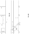
- Figure 4A is a side view of a guideway mounted vehicle 402, in accordance with one or more embodiments.
- Vehicle 402 comprises the features discussed with respect to vehicle 102 ( Figure 1 ).
- Vehicle 402 includes vehicle localization system 100 ( Figure 1 ), and is configured to move over guideway 414.
- Guideway 414 is a two-rail example of guideway 114 ( Figure 1 ).
- Markers 420a-420n, where n is an integer greater than 1, correspond to markers 120 ( Figure 1 ).
- Markers 420a-420n are on the wayside of the guideway 414. In this example embodiment, markers 420a-420n are posts on the wayside of the guideway 414 separated by the distance d.
- Figure 4B is a top-side view of vehicle 402, in accordance with one or more embodiments.
- Vehicle 402 is configured to travel over guideway 414.
- Markers 420a-420n are on the wayside of the guideway 414.
- First sensor 410a corresponds to first sensor 110a ( Figure 1 ).
- First sensor 410a is positioned on the first end of vehicle 402 at a distance L from the markers 420a-420n.
- First sensor 410a is directed toward markers 420a-420n. Accordingly, first sensor 410a has an inclination angle ⁇ that corresponds to inclination angle ⁇ 1 ( Figure 1 ) of the first sensor 110a.
- First sensor 410a has a field of view FOV that corresponds to field of view 122a ( Figure 1 ).
- first sensor 410a Based on the inclination angle ⁇ , the field of view FOV, and the distance L, first sensor 410a has a detection span I.
- sensors of the first set of sensors 110 ( Figure 1 ) and the sensors of the second set of sensors 112 ( Figure 1 ) have properties similar to those discussed with respect to sensor 410a that vary based on the position of the sensor on the vehicle 102.
- FIG 5 is a flowchart of a method 500 of determining a position, a distance traveled, and a velocity of a guideway mounted vehicle, in accordance with one or more embodiments.
- one or more steps of method 500 is implemented by a controller such as controller 108 ( Figure 1 ).
- step 501 the vehicle moves from a start position such as a known or a detected marker in one of a first direction or a second direction.
- one or more sensors generate sensor data based on a detection of a marker of a plurality of markers using a set of sensors on the first end or on the second end of the vehicle.
- Each sensor of the set of sensors on the first end or the second end of the vehicle is configured to generate corresponding sensor data.
- the sensors detect a pattern of objects on a guideway along which the vehicle moves, and the controller recognizes the pattern of objects as the detected marker of the plurality of markers based on data stored in a memory comprising information describing the detected marker of the plurality of markers.
- step 505 the controller compares a time a first sensor detected the marker of the plurality of markers with a time a second sensor detected the marker of the plurality of markers. Then, based on the time comparison, the controller identifies the first end or the second end as a leading end of the vehicle.
- the controller calculates a position of the vehicle by calculating one or more of a position of the leading end of the vehicle based on the sensor data generated by one or more of the first sensor or the second sensor, or calculating a position of the end of the vehicle that is other than the leading end of the vehicle based on the position of the leading end of the vehicle and a length of the vehicle.
- the controller calculates a distance the vehicle traveled from the start position or a detected marker.
- the controller counts a quantity of markers of the plurality of markers detected by the set of sensors on the first end of the vehicle within a predetermined duration of time, and then calculates the distance the vehicle traveled during the predetermined duration of time based on a total quantity of the detected markers and the distance between each of the equally spaced markers of the plurality of markers.
- step 511 the controller calculates a velocity of the vehicle with respect to the detected marker of the plurality of markers based on the distance the vehicle traveled over a predetermined duration of time or a relative velocity of the vehicle with respect to the detected marker of the plurality of markers.
- FIG 6 is a flowchart of a method 600 for checking consistency between the sensors on a same end of the vehicle, in accordance with one or more embodiments.
- one or more steps of method 600 is implemented by a controller such as controller 108 ( Figure 1 ) and a set of sensors A and B.
- Sensors A and B are a pair of sensors on a same end of the vehicle such as, the first set of sensors 110 ( Figure 1 ) or the second set of sensors 112 ( Figure 1 ).
- sensor A detects an object such as a marker 120 ( Figure 1 ) and generates sensor data based on the detected object.
- the sensor data comprises a range (e.g., distance) between sensor A and the detected object and the relative velocity of sensor A with respect to the detected object.
- the controller Based on the sensor data generated by sensor A, the controller calculates the velocity of the vehicle, calculates the distance the vehicle traveled, and determines the leading end of the vehicle.
- sensor B detects the object and generates sensor data based on the detected object.
- the sensor data comprises a range (e.g., distance) between sensor B and the detected object and the relative velocity of sensor B with respect to the detected object.
- the controller Based on the sensor data generated by sensor B, the controller calculates the velocity of the vehicle, calculates the distance the vehicle traveled, and determines the leading end of the vehicle.
- step 605 the controller compares the velocity of the vehicle that is determined based on the sensor data generated by sensor A with the velocity of the vehicle that is determined based on the sensor data generated by sensor B. In some embodiments, if the values match, then the controller determines sensor A and sensor B are functioning properly. If the values differ by more than a predefined tolerance, then the controller identifies one or more of sensor A or sensor B as being faulty. In some embodiments, if the velocity values match within the predefined threshold, then the controller is configured to use an average of the velocity values as the velocity of the vehicle.
- the controller compares the distance the vehicle traveled that is determined based on the sensor data generated by sensor A with the distance the vehicle traveled that is determined based on the sensor data generated by sensor B. In some embodiments, if the values match, then the controller determines sensor A and sensor B are functioning properly. If the values differ by more than a predefined tolerance, then the controller identifies one or more of sensor A or sensor B as being faulty. In some embodiments, if the distance values the vehicle traveled match within the predefined threshold, then the controller is configured to use an average of the distance traveled values as the distance the vehicle traveled.
- step 609 the controller compares the leading end of the vehicle that is determined based on the sensor data generated by sensor A with the leading end of the vehicle that is determined based on the sensor data generated by sensor B. In some embodiments, if the values match, then the controller determines sensor A and sensor B are functioning properly. If the values differ by more than a predefined tolerance, then the controller identifies one or more of sensor A or sensor B as being faulty. In some embodiments, the controller determines that sensor A and sensor B are functioning properly (e.g., not faulty) if each of the results of step 605, 607 and 609 are yes.
- FIG 7 is a flowchart of a method 700 for checking consistency between the sensors on a same end of the vehicle, in accordance with one or more embodiments.
- one or more steps of method 700 is implemented by a controller such as controller 108 ( Figure 1 ), a set of sensors A and B, and an auxiliary sensor C.
- Sensors A and B are a pair of sensors on a same end of the vehicle such as, the first set of sensors 110 ( Figure 1 ) or the second set of sensors 112 ( Figure 1 ).
- Auxiliary sensor C is, for example, a sensor such as first auxiliary sensor 110c ( Figure 1 ) or second auxiliary sensor 112c.
- sensor A detects an object such as a marker 120 ( Figure 1 ) and generates sensor data based on the detected object.
- the sensor data comprises a range (e.g., distance) between sensor A and the detected object and the relative velocity of sensor A with respect to the detected object.
- the controller Based on the sensor data generated by sensor A, the controller calculates the velocity of the vehicle, calculates the distance the vehicle traveled, and determines the leading end of the vehicle.
- sensor B detects the object and generates sensor data based on the detected object.
- the sensor data comprises a range (e.g., distance) between sensor B and the detected object and the relative velocity of sensor B with respect to the detected object.
- the controller Based on the sensor data generated by sensor B, the controller calculates the velocity of the vehicle, calculates the distance the vehicle traveled, and determines the leading end of the vehicle.
- step 705 sensor C detects the object and generates sensor data based on the detected object.
- the sensor data comprises a range (e.g., distance) between sensor C and the detected object and the relative velocity of sensor C with respect to the detected object.
- the controller Based on the sensor data generated by sensor C, the controller calculates the velocity of the vehicle, calculates the distance the vehicle traveled, and determines the leading end of the vehicle.
- the controller compares one or more of the sensor data generated by sensor A with the corresponding sensor data generated by sensor B. For example, the controller compares one or more of the velocity of the vehicle that is determined based on the sensor data generated by sensor A with the velocity of the vehicle that is determined based on the sensor data generated by sensor B, the distance the vehicle traveled that is determined based on the sensor data generated by sensor A with the distance the vehicle traveled that is determined based on the sensor data generated by sensor B, or the leading end of the vehicle that is determined based on the sensor data generated by sensor A with the leading end of the vehicle that is determined based on the sensor data generated by sensor B. If the values match, then the controller determines sensor A and sensor B are functioning properly (e.g., not faulty). If the values differ by more than a predefined tolerance, then the controller identifies one or more of sensor A or sensor B as being faulty.
- step 709 controller activates sensor C.
- step 709 is executed prior to one or more of steps 701, 703, 705 or 707.
- the controller compares one or more of the sensor data generated by sensor A with the corresponding sensor data generated by sensor C. For example, the controller compares one or more of the velocity of the vehicle that is determined based on the sensor data generated by sensor A with the velocity of the vehicle that is determined based on the sensor data generated by sensor C, the distance the vehicle traveled that is determined based on the sensor data generated by sensor A with the distance the vehicle traveled that is determined based on the sensor data generated by sensor C, or the leading end of the vehicle that is determined based on the sensor data generated by sensor A with the leading end of the vehicle that is determined based on the sensor data generated by sensor C.
- the controller determines sensor A and sensor C are functioning properly (e.g., not faulty), and the controller identifies sensor B as being faulty. If the values differ by more than the predefined tolerance, then the controller identifies one or more of sensor A or sensor C as being faulty.
- the controller compares one or more of the sensor data generated by sensor B with the sensor data generated by sensor C. For example, the controller compares one or more of the velocity of the vehicle that is determined based on the sensor data generated by sensor B with the velocity of the vehicle that is determined based on the sensor data generated by sensor C, the distance the vehicle traveled that is determined based on the sensor data generated by sensor B with the distance the vehicle traveled that is determined based on the sensor data generated by sensor C, or the leading end of the vehicle that is determined based on the sensor data generated by sensor B with the leading end of the vehicle that is determined based on the sensor data generated by sensor C.
- the controller determines sensor B and sensor C are functioning properly (e.g., not faulty), and the controller identifies sensor A as being faulty. If the values differ by more than the predefined tolerance, then the controller identifies two or more of sensor A, sensor B or sensor C as being faulty.
- FIG 8 is a flowchart of a method 800 for checking consistency between sensors on opposite ends of the vehicle, in accordance with one or more embodiments.
- one or more steps of method 800 is implemented by a controller such as controller 108 ( Figure 1 ) and sensors A and B.
- Sensors A is, for example, a sensor such as first sensor 110a ( Figure 1 ).
- Sensor B is, for example, a sensor such as third sensor 112a ( Figure 1 ).
- sensor A detects an object such as a marker 120 ( Figure 1 ) and generates sensor data based on the detected object.
- the sensor data comprises a range (e.g., distance) between sensor A and the detected object and the relative velocity of sensor A with respect to the detected object.
- the controller Based on the sensor data generated by sensor A, the controller calculates the velocity of the vehicle, calculates the distance the vehicle traveled, and determines the leading end of the vehicle.
- sensor B on the opposite end of the vehicle, detects the object and generates sensor data based on the detected object.
- the sensor data comprises a range (e.g., distance) between sensor B and the detected object and the relative velocity of sensor B with respect to the detected object.
- the controller Based on the sensor data generated by sensor B, the controller calculates the velocity of the vehicle, calculates the distance the vehicle traveled, and determines the leading end of the vehicle.
- step 805 the controller compares the velocity of the vehicle that is determined based on the sensor data generated by sensor A with the velocity of the vehicle that is determined based on the sensor data generated by sensor B. In some embodiments, if the magnitudes match, then the controller determines sensor A and sensor B are functioning properly (e.g., not faulty). If the magnitudes differ by more than a predefined tolerance, then the controller identifies one or more of sensor A or sensor B as being faulty.
- the controller is configured to compare the magnitudes of the velocities determined based on the sensor data generated by sensor A and sensor B because the sensor on the leading end of the vehicle will generate sensor data that results in a negative velocity as the vehicle approaches the detected marker, and the sensor on the non-leading end of the vehicle will generate sensor data that results in a positive velocity as the vehicle departs from the detected marker. In some embodiments, if the velocity values match within the predefined threshold, then the controller is configured to use an average of the velocity values as the velocity of the vehicle.
- the controller compares the distance the vehicle traveled that is determined based on the sensor data generated by sensor A with the distance the vehicle traveled that is determined based on the sensor data generated by sensor B. In some embodiments, if the values match, then the controller determines sensor A and sensor B are functioning properly (e.g., not faulty). If the values differ by more than a predefined tolerance, then the controller identifies one or more of sensor A or sensor B as being faulty. In some embodiments, if the distance the vehicle traveled values match within the predefined threshold, then the controller is configured to use an average of the distance traveled values as the distance the vehicle traveled.
- step 809 the controller compares the leading end of the vehicle that is determined based on the sensor data generated by sensor A with the leading end of the vehicle that is determined based on the sensor data generated by sensor B. In some embodiments, if the values match, then the controller determines sensor A and sensor B are functioning properly (e.g., not faulty). If the values differ by more than a predefined tolerance, then the controller identifies one or more of sensor A or sensor B as being faulty. In some embodiments, the controller determines that sensor A and sensor B are functioning properly (e.g., not faulty) if each of the results of step 805, 807 and 809 are yes.
- FIG 9 is a block diagram of a vehicle on board controller (“VOBC") 500, in accordance with one or more embodiments.
- VOBC 500 is usable in place of one or more of controller 108 ( Figure 1 ) or data fusion center 230 ( Figure 2 ), alone or in combination with memory 109 ( Figure 1 ).
- VOBC 900 includes a specific-purpose hardware processor 902 and a non-transitory, computer readable storage medium 904 encoded with, i.e., storing, the computer program code 906, i.e., a set of executable instructions.
- Computer readable storage medium 904 is also encoded with instructions 907 for interfacing with manufacturing machines for producing the memory array.
- the processor 902 is electrically coupled to the computer readable storage medium 904 via a bus 908.
- the processor 902 is also electrically coupled to an I/O interface 910 by bus 908.
- a network interface 912 is also electrically connected to the processor 902 via bus 908.
- Network interface 912 is connected to a network 914, so that processor 902 and computer readable storage medium 904 are capable of connecting to external elements via network 914.
- VOBC 900 further includes data fusion center 916.
- the processor 902 is connected to data fusion center 916 via bus 908.
- the processor 902 is configured to execute the computer program code 906 encoded in the computer readable storage medium 904 in order to cause system 900 to be usable for performing a portion or all of the operations as described in method 500, 600, 700, or 800.
- the processor 902 is a central processing unit (CPU), a multi-processor, a distributed processing system, an application specific integrated circuit (ASIC), and/or a suitable processing unit.
- CPU central processing unit
- ASIC application specific integrated circuit
- the computer readable storage medium 904 is an electronic, magnetic, optical, electromagnetic, infrared, and/or a semiconductor system (or apparatus or device).
- the computer readable storage medium 904 includes a semiconductor or solid-state memory, a magnetic tape, a removable computer diskette, a random access memory (RAM), a read-only memory (ROM), a rigid magnetic disk, and/or an optical disk.
- the computer readable storage medium 904 includes a compact disk-read only memory (CD-ROM), a compact disk-read/write (CD-R/W), and/or a digital video disc (DVD).
- the storage medium 904 stores the computer program code 906 configured to cause system 900 to perform method 500, 600, 700 or 800. In some embodiments, the storage medium 904 also stores information needed for performing method 500, 600, 700 or 800 as well as information generated during performing the method 500, 600, 700 or 800 such as a sensor information parameter 920, a guideway database parameter 922, a vehicle location parameter 924, a vehicle speed parameter 926, a vehicle leading end parameter 928, and/or a set of executable instructions to perform the operation of method 500, 600, 700 or 800.
- information needed for performing method 500, 600, 700 or 800 as well as information generated during performing the method 500, 600, 700 or 800 such as a sensor information parameter 920, a guideway database parameter 922, a vehicle location parameter 924, a vehicle speed parameter 926, a vehicle leading end parameter 928, and/or a set of executable instructions to perform the operation of method 500, 600, 700 or 800.
- the storage medium 904 stores instructions 907 to effectively implement method 500, 600, 700 or 800.
- VOBC 900 includes I/O interface 910.
- I/O interface 910 is coupled to external circuitry.
- I/O interface 910 includes a keyboard, keypad, mouse, trackball, trackpad, and/or cursor direction keys for communicating information and commands to processor 902.
- VOBC 900 also includes network interface 912 coupled to the processor 902.
- Network interface 912 allows VOBC 900 to communicate with network 914, to which one or more other computer systems are connected.
- Network interface 912 includes wireless network interfaces such as BLUETOOTH, WIFI, WIMAX, GPRS, or WCDMA; or wired network interface such as ETHERNET, USB, or IEEE-1394.
- method 500, 600, 700 or 800 is implemented in two or more VOBCs 900, and information such as memory type, memory array layout, I/O voltage, I/O pin location and charge pump are exchanged between different VOBCs 900 via network 914.
- VOBC further includes data fusion center 916.
- Data fusion center 916 is similar to data fusion center 230 ( Figure 2 ).
- data fusion center 916 is integrated with VOBC 900.
- the data fusion center is separate from VOBC 900 and connects to the VOBC 900 through I/O interface 910 or network interface 912.
- VOBC 900 is configured to receive sensor information related to a fusion sensor arrangement, e.g., fusion sensor arrangement 200 ( Figure 2 ), through data fusion center 916.
- the information is stored in computer readable medium 904 as sensor information parameter 920.
- VOBC 900 is configured to receive information related to the guideway database through I/O interface 910 or network interface 912.
- the information is stored in computer readable medium 904 as guideway database parameter 922.
- VOBC 900 is configured to receive information related to vehicle location through I/O interface 910, network interface 912 or data fusion center 916.
- the information is stored in computer readable medium 904 as vehicle location parameter 924.
- VOBC 900 is configured to receive information related to vehicle speed through I/O interface 910, network interface 912 or data fusion center 916.
- the information is stored in computer readable medium 904 as vehicle speed parameter 926.
- processor 902 executes a set of instructions to determine the location and speed of the guideway mounted vehicle, which are used to update vehicle location parameter 924 and vehicle speed parameter 926.
- Processor 902 is further configured to receive LMA instructions and speed instructions from a centralized or de-centralized control system.
- Processor 902 determines whether the received instructions are in conflict with the sensor information.
- Processor 902 is configured to generate instructions for controlling an acceleration and braking system of the guideway mounted vehicle to control travel along the guideway.
- An aspect of this description relates to a system comprising a set of sensors on a first end of a vehicle having the first end and a second end, and a controller coupled with the set of sensors.
- the sensors of the set of sensors are each configured to generate corresponding sensor data based on a detected marker of a plurality of markers along a direction of movement of the vehicle.
- a first sensor of the set of sensors has a first inclination angle with respect to the detected marker of the plurality of markers
- a second sensor of the set of sensors has a second inclination angle with respect to the detected marker of the plurality of markers different from the first inclination angle.
- the controller is configured to compare a time the first sensor detected the marker of the plurality of markers with a time the second sensor detected the marker of the plurality of markers.
- the controller is also configured to identify the first end or the second end as a leading end of the vehicle based on the comparison of the time the first sensor detected the marker of the plurality of markers with the time the second sensor detected the marker of the plurality of markers.
- the controller is further configured to calculate a position of the leading end of the vehicle based on the sensor data generated by one or more of the first sensor or the second sensor.
- Another aspect of this description relates to a method comprising generating sensor data based on a detection of a marker of a plurality markers along a direction of movement of a vehicle having a first end and a second end using a set of sensors on the first end of the vehicle.
- Each sensor of the set of sensors on the first end of the vehicle is configured to generate corresponding sensor data.
- a first sensor of the set of sensors has a first inclination angle with respect to the detected marker of the plurality of markers, and a second sensor of the set of sensors has a second inclination angle with respect to the detected marker of the plurality of markers different from the first inclination angle.
- the method also comprises comparing a time the first sensor detected the marker of the plurality of markers with a time the second sensor detected the marker of the plurality of markers.
- the method further comprises identifying the first end or the second end as a leading end of the vehicle based on the comparison of the time the first sensor detected the marker of the plurality of markers with the time the second sensor detected the marker of the plurality of markers.
- the method additionally comprises calculating a position of the leading end of the vehicle based on the sensor data generated by one or more of the first sensor or the second sensor.
Landscapes
- Engineering & Computer Science (AREA)
- Mechanical Engineering (AREA)
- Train Traffic Observation, Control, And Security (AREA)
- Traffic Control Systems (AREA)
- Navigation (AREA)
- Length Measuring Devices With Unspecified Measuring Means (AREA)
Claims (20)
- System, umfassend:einen Sensorsatz (110) an einem Fahrzeug (102), das das erste Ende (104) und ein zweites Ende (106) aufweist, wobei die Sensoren des Sensorsatzes (110) jeweils so ausgelegt sind, dass sie auf Basis einer erfassten Markierung (120) aus einer Vielzahl von Markierungen (120a-120n) entlang einer Bewegungsrichtung des Fahrzeugs entsprechende Sensordaten erzeugen, ein erster Sensor (110a) des Sensorsatzes (110) einen ersten Neigungswinkel (al) in Bezug auf die erfasste Markierung (120) aus der Vielzahl von Markierungen (120a-120n) aufweist, und ein zweiter Sensor (110b) des Sensorsatzes (110) einen zweiten Neigungswinkel (ot2) in Bezug auf die erfasste Markierung (120) aus der Vielzahl von Markierungen (120a-120n) aufweist, der sich vom ersten Neigungswinkel (al) unterscheidet; undeine Steuerung (108), die mit dem Sensorsatz (110, 112) gekoppelt ist, wobei die Steuerung (108) so ausgelegt ist, dass sie:einen Zeitpunkt, zu dem der erste Sensor (110a, 112a) die Markierung aus der Vielzahl von Markierungen (120a-120n) erfasst hat, mit einem Zeitpunkt vergleicht, zu dem der zweite Sensor (110b) die Markierung aus der Vielzahl von Markierungen (120a-120n) erfasst hat;auf Basis des Vergleichs des Zeitpunkts, zu dem der erste Sensor (110a, 112b) die Markierung (120) aus der Vielzahl von Markierungen (120a-120n) erfasst hat, mit dem Zeitpunkt, zu dem der zweite Sensor (110b) die Markierung (120) aus der Vielzahl von Markierungen (120a-120n) erfasst hat, das erste Ende (104) oder das zweite Ende (106) als ein voranfahrendes Ende des Fahrzeugs (102) identifiziert; undauf Basis der Sensordaten, die von einem oder mehreren aus dem ersten Sensor (110a) oder dem zweiten Sensor (110b) erzeugt wurden, eine Position des voranfahrenden Endes des Fahrzeugs (102) berechnet,dadurch gekennzeichnet, dass sich der Sensorsatz (110, 112) am ersten Ende (104) des Fahrzeugs (102) befindet und der erste Sensor (110a) und der zweite Sensor (110b) auf unterschiedlichen Höhen angeordnet sind.
- System (100) nach Anspruch 1, wobei die Position des voranfahrenden Endes des Fahrzeugs (102) auf Basis einer Entfernung zwischen einer ersten Markierung (120) aus der Vielzahl von Markierungen (120a-120n) und der erfassten Markierung (120) aus der Vielzahl von Markierungen (120a-120n) berechnet wird.
- System (100) nach Anspruch 1, wobei es sich bei aufeinanderfolgenden Markierungen (120) aus der Vielzahl von Markierungen (120a-120n) um Paare von Markierungen (120) handelt, welche durch eine Entfernung getrennt sind, die in einem Speicher gespeichert ist, und die Steuerung (108) weiter so ausgelegt ist, dass sie eine Anzahl von Markierungen (120) aus der Vielzahl von Markierungen (120a-120n), die während einer vorbestimmten Zeitdauer vom Sensorsatz (110, 112) erfasst werden, zählt;
den Speicher nach der gespeicherten Entfernung zwischen jedem Paar aufeinanderfolgender Markierungen (120) aus der Vielzahl von Markierungen (120a-120n), die während der vorbestimmten Zeitdauer vom Sensorsatz (110, 112) erfasst wurden, durchsucht; und
für die Anzahl von Markierungen (120), die vom Sensorsatz (110, 112) erfasst wurden, die Entfernungen zwischen jedem Paar aufeinanderfolgender Markierungen (120) aus der Vielzahl von Markierungen (120a-120n) addiert, um eine Entfernung zu bestimmen, die das Fahrzeug (102) während der vorbestimmten Zeitdauer zurückgelegt hat. - System nach Anspruch 3, wobei die Steuerung (108) weiter so ausgelegt ist, dass sie auf Basis der Entfernung, die das Fahrzeug (102) zurückgelegt hat, und der vorbestimmten Zeitdauer eine Geschwindigkeit des Fahrzeugs (102) berechnet.
- System nach Anspruch 1, wobei
eine oder mehrere Markierungen (120) aus der Vielzahl von Markierungen (120a-120n) ein Muster von Objekten umfassen,
die Sensoren des Sensorsatzes (110, 112) so ausgelegt sind, dass sie auf Basis des Musters von Objekten die eine oder die mehreren Markierungen (120) erkennen. - System nach Anspruch 1, wobei ein Sichtfeld einer ersten Markierung (120) auf dem ersten Neigungswinkel basiert, ein Sichtfeld einer zweiten Markierung auf dem zweiten Neigungswinkel (al) basiert, und die Markierungen (120) aus der Vielzahl von Markierungen (120a-120n) entlang der Bewegungsrichtung des Fahrzeugs (102) derart beabstandet sind, dass die erfasste Markierung (120) aus der Vielzahl von Markierungen (120a-120n) darauf beschränkt ist, dass sie in einem aus dem Sichtfeld der ersten Markierung (120) oder dem Sichtfeld der zweiten Markierung liegt.
- System nach Anspruch 1, wobei das Fahrzeug (102) so ausgelegt ist, dass es sich entlang eines Fahrwegs (114) bewegt, und sich eine oder mehrere Markierungen (120) aus der Vielzahl von Markierungen (120a-120n) am Fahrweg (114) befinden.
- System nach Anspruch 1, wobei das Fahrzeug (102) so ausgelegt ist, dass es sich entlang eines Fahrwegs (114) bewegt, und sich eine oder mehrere Markierungen (120) aus der Vielzahl von Markierungen (120a-120n) an einem Wegrand des Fahrwegs (114) befinden.
- System nach Anspruch 1, wobei der Sensorsatz (110, 112) weiter einen dritten Sensor (112a) umfasst, und die Steuerung (108) weiter so ausgelegt ist, dass sie
einen ersten berechneten Wert, der auf den vom ersten Sensor erzeugten Sensordaten basiert, mit einem zweiten berechneten Wert vergleicht, der auf den vom zweiten Sensor (110b) erzeugten Sensordaten basiert,
auf Basis einer Bestimmung, dass sich der erste berechnete Wert um mehr als eine vordefinierte Schwelle vom zweiten berechneten Wert unterscheidet, einen aus dem ersten Sensor (110a) oder dem zweiten Sensor (110b) als defekt identifiziert,
den dritten Sensor (112a) aktiviert,
einen dritten berechneten Wert, der auf den vom dritten Sensor (112a) erzeugten Sensordaten basiert, mit dem ersten berechneten Wert und mit dem zweiten berechneten Wert vergleicht, und
auf Basis einer Bestimmung, dass der erste berechnete Wert innerhalb der vordefinierten Schwelle mit dem dritten berechneten Wert zusammenpasst, oder der zweite berechnete Wert innerhalb der vordefinierten Schwelle mit dem dritten berechneten Wert zusammenpasst, identifiziert, welcher aus dem ersten Sensor (110a) oder dem zweiten Sensor (110b) defekt ist. - System nach Anspruch 9, wobei es sich bei jedem aus dem ersten berechneten Wert und dem zweiten berechneten Wert um die Identifikation des voranfahrenden Endes des Fahrzeugs (102), die Position des voranfahrenden Endes des Fahrzeugs (102), eine Entfernung, die das Fahrzeug (102) zurückgelegt hat, oder eine Geschwindigkeit des Fahrzeugs (102) handelt.
- System nach Anspruch 1, weiter umfassend:einen Sensorsatz (110, 112) am zweiten Ende (106) des Fahrzeugs (102), wobei die Sensoren des Sensorsatzes (110, 112) am zweiten Ende (106) des Fahrzeugs (102) jeweils so ausgelegt sind, dass sie auf Basis der erfassten Markierung (120) aus der Vielzahl von Markierungen (120) entsprechende Sensordaten erzeugen, ein dritter Sensor (112a) des Sensorsatzes (110, 112) am zweiten Ende (106) des Fahrzeugs (102) einen dritten Neigungswinkel (ßi) in Bezug auf die erfasste Markierung (120) aus der Vielzahl von Markierungen (120) aufweist, und ein vierter Sensor des Sensorsatzes (110, 112) am zweiten Ende (106) des Fahrzeugs (102) einen vierten Neigungswinkel in Bezug auf die erfasste Markierung (120) aus der Vielzahl von Markierungen (120a-120n) aufweist, der sich vom dritten Neigungswinkel unterscheidet,wobei die Steuerung (108) weiter so ausgelegt ist, dass sieeinen Zeitpunkt, zu dem der dritte Sensor (112a) die Markierung (120) aus der Vielzahl von Markierungen (120a-120n) erfasst hat, mit einem Zeitpunkt vergleicht, zu dem der vierte Sensor (112b) die Markierung aus der Vielzahl von Markierungen (120) erfasst hat;auf Basis des Vergleichs des Zeitpunkts, zu dem der dritte Sensor (112a) die Markierung aus der Vielzahl von Markierungen (120a-120n) erfasst hat, mit dem Zeitpunkt, zu dem der vierte Sensor (112b) die Markierung aus der Vielzahl von Markierungen (120a-120n) erfasst hat, das erste Ende (104) oder das zweite Ende (106) als das voranfahrende Ende des Fahrzeugs (102) identifiziert; undauf Basis der Sensordaten, die von einem oder mehreren aus dem dritten Sensor (112a) oder dem vierten Sensor (112b) erzeugt wurden, die Position des voranfahrenden Endes des Fahrzeugs (102) berechnet.
- System nach Anspruch 11, wobei
die Steuerung (108) weiter so ausgelegt ist, dass sie:einen ersten berechneten Wert, der auf den von einem oder mehreren aus dem ersten Sensor oder dem zweiten Sensor (110b, 112b) erzeugten Sensordaten basiert, mit einem zweiten berechneten Wert vergleicht, der auf den von einem oder mehreren aus dem dritten Sensor oder dem vierten Sensor erzeugten Sensordaten basiert; undauf Basis einer Bestimmung, dass sich der erste berechnete Wert um mehr als eine vordefinierte Schwelle vom zweiten berechneten Wert unterscheidet, einen aus dem ersten Sensor (110a), dem zweiten Sensor (110b), dem dritten Sensor (112a) oder dem vierten Sensor (112b) als defekt identifiziert. - System nach Anspruch 12, wobei es sich bei jedem aus dem ersten berechneten Wert und dem zweiten berechneten Wert um die Identifikation des voranfahrenden Endes des Fahrzeugs (102), die Position des voranfahrenden Endes des Fahrzeugs (102), eine Entfernung, die das Fahrzeug (102) zurückgelegt hat, oder eine Geschwindigkeit des Fahrzeugs (102) handelt.
- System nach Anspruch 11, wobei die Steuerung (108) weiter so ausgelegt ist, dass sie
auf Basis der Sensordaten, die von dem Sensorsatz (110, 112) an dem Ende des Fahrzeugs (102) erzeugt wurden, das als das voranfahrende Ende des Fahrzeugs (102) identifiziert wurde, eine erste Geschwindigkeit des voranfahrenden Endes des Fahrzeugs (102) berechnet;
auf Basis der Sensordaten, die von dem Sensorsatz (110, 112) an dem Ende des Fahrzeugs (102) erzeugt wurden, bei dem es sich nicht um das voranfahrende Ende des Fahrzeugs (102) handelt, eine zweite Geschwindigkeit des anderen aus dem ersten Ende (104) oder dem zweiten Ende (106), bei dem es sich nicht um das voranfahrende Ende des Fahrzeugs (102) handelt, berechnet; und
auf Basis einer Bestimmung, dass sich eine Größe der ersten Geschwindigkeit um mehr als eine vordefinierte Schwelle von einer Größe der zweiten Geschwindigkeit unterscheidet, einen Alarm erzeugt. - System nach Anspruch 1, wobei das Fahrzeug (102) mindestens eines aus einem Rad und einem Getriebe umfasst, und die Sensoren des Sensorsatzes (110, 112) unabhängig vom Rad und dem Getriebe am ersten Ende (104) des Fahrzeugs (102) positioniert sind.
- Verfahren, umfassend:Erzeugen von Sensordaten auf Basis einer Erfassung einer Markierung (120) aus einer Vielzahl von Markierungen (120a-120n) entlang einer Bewegungsrichtung eines Fahrzeugs (102), das ein erste Ende (104) und ein zweites Ende (106) aufweist, unter Verwendung eines Sensorsatzes (110, 112) am Fahrzeug (102), wobei jeder Sensor des Sensorsatzes (110, 112) am ersten Ende (104) des Fahrzeugs (102) so ausgelegt ist, dass er entsprechende Sensordaten erzeugt, ein erster Sensor (110a) des Sensorsatzes (110, 112) einen ersten Neigungswinkel (al) in Bezug auf die erfasste Markierung (120) aus der Vielzahl von Markierungen (120) aufweist, und ein zweiter Sensor (110b) des Sensorsatzes (110, 112) einen zweiten Neigungswinkel (ot2) in Bezug auf die erfasste Markierung (120) aus der Vielzahl von Markierungen (120a-120n) aufweist, der sich vom ersten Neigungswinkel (al) unterscheidet;Vergleichen eines Zeitpunkts, zu dem der erste Sensor die Markierung (120) aus der Vielzahl von Markierungen (120a-120n) erfasst hat, mit einem Zeitpunkt, zu dem der zweite Sensor (110b) die Markierung aus der Vielzahl von Markierungen (120a-120n) erfasst hat;Identifizieren des ersten Endes (104) oder des zweiten Endes (106) als ein voranfahrendes Ende des Fahrzeugs (102) auf Basis des Vergleichs des Zeitpunkts, zu dem der erste Sensor (110a) die Markierung (120) aus der Vielzahl von Markierungen (120a-120n) erfasst hat, mit dem Zeitpunkt, zu dem der zweite Sensor (110b) die Markierung (120) aus der Vielzahl von Markierungen (120a-120n) erfasst hat; undBerechnen einer Position des voranfahrenden Endes des Fahrzeugs (102) auf Basis der Sensordaten, die von einem oder mehreren aus dem ersten Sensor (110a) oder dem zweiten Sensor (110b) erzeugt wurden,dadurch gekennzeichnet, dass der Sensorsatz (110, 112) am ersten Ende (104) des Fahrzeugs (102) positioniert ist, und der erste Sensor (110a) und der zweite Sensor (110b) auf unterschiedlichen Höhen angeordnet sind.
- Verfahren nach Anspruch 16, weiter umfassend:Erfassen eines Musters von Objekten an einem Fahrweg (114), entlang dem sich das Fahrzeug (102) bewegt; undErkennen des Musters von Objekten als die erfasste Markierung (120) aus der Vielzahl von Markierungen (120a-120n) auf Basis von in einem Speicher gespeicherten Daten, die Informationen umfassen, welche die erfasste Markierung (120) aus der Vielzahl von Markierungen (120a-120n) beschreiben.
- Verfahren nach Anspruch 16, weiter umfassend:
Berechnen einer Position des Endes des Fahrzeugs (102), bei dem es sich nicht um das voranfahrende Ende des Fahrzeugs (102) handelt, auf Basis der Position des voranfahrenden Endes des Fahrzeugs (102) und einer Länge des Fahrzeugs (102). - Verfahren nach Anspruch 16, wobei die Markierungen (120) aus der Vielzahl von Markierungen (120a-120n) entlang der Bewegungsrichtung des Fahrzeugs (102) gleichmäßig beabstandet sind, und das Verfahren weiter umfasst:Zählen einer Anzahl von Markierungen (120) aus der Vielzahl von Markierungen (120a-120n), die innerhalb einer vorbestimmten Zeitdauer vom Sensorsatz (110, 112) am ersten Ende (104) des Fahrzeugs (102) erfasst werden; undBerechnen einer Entfernung, die das Fahrzeug (102) während der vorbestimmten Zeitdauer zurückgelegt hat, auf Basis einer Gesamtanzahl der erfassten Markierungen (120) und der Entfernung zwischen jeder der gleichmäßig beabstandeten Markierungen aus der Vielzahl von Markierungen (120a-120n).
- Verfahren nach Anspruch 16, weiter umfassend:Erzeugen von Sensordaten auf Basis einer Erfassung der Markierung aus der Vielzahl von Markierungen (120a-120n) unter Verwendung eines Sensorsatzes (110, 112) am zweiten Ende (106) des Fahrzeugs (102), wobei jeder Sensor des Sensorsatzes (110, 112) am zweiten Ende (106) des Fahrzeugs (102) so ausgelegt ist, dass er entsprechende Sensordaten erzeugt, ein dritter Sensor (112a) des Sensorsatzes (110, 112) am zweiten Ende (106) des Fahrzeugs (102) einen dritten Neigungswinkel (ßi) in Bezug auf die erfasste Markierung (120) aus der Vielzahl von Markierungen (120) aufweist, und ein vierter Sensor des Sensorsatzes (110, 112) am zweiten Ende (106) des Fahrzeugs (102) einen zweiten Neigungswinkel (ot2) in Bezug auf die erfasste Markierung (120) aus der Vielzahl von Markierungen (120a-120n) aufweist, der sich vom dritten Neigungswinkel(βi) unterscheidet;Vergleichen eines Zeitpunkts, zu dem der dritte Sensor die Markierung (120) aus der Vielzahl von Markierungen (120a-120n) erfasst hat, mit einem Zeitpunkt, zu dem der vierte Sensor (112b) die Markierung aus der Vielzahl von Markierungen (120a-120n) erfasst hat;Identifizieren des ersten Endes (104) oder des zweiten Endes (106) als das voranfahrende Ende des Fahrzeugs (102) auf Basis des Vergleichs des Zeitpunkts, zu dem der dritte Sensor (112a) die Markierung aus der Vielzahl von Markierungen (120a-120n) erfasst hat, mit dem Zeitpunkt, zu dem der vierte Sensor (112b) die Markierung aus der Vielzahl von Markierungen (120a-120n) erfasst hat;Berechnen der Position des voranfahrenden Endes des Fahrzeugs (102) auf Basis der Sensordaten, die von einem oder mehreren aus dem dritten Sensor (112a) oder dem vierten Sensor (112b) erzeugt wurden; undErzeugen eines Alarms, wenn die Position des voranfahrenden Endes des Fahrzeugs (102), die auf Basis der Sensordaten berechnet wird, die von einem oder mehreren aus dem ersten Sensor (110a) oder dem zweiten Sensor (110b) erzeugt wurden, sich um mehr als eine vordefinierte Schwelle von der Position des voranfahrenden Endes des Fahrzeugs (102), die auf Basis der Sensordaten berechnet wird, die von einem oder mehreren aus dem dritten Sensor (112a) oder dem vierten Sensor (112b) erzeugt wurden, unterscheidet.
Applications Claiming Priority (2)
| Application Number | Priority Date | Filing Date | Title |
|---|---|---|---|
| US201562210218P | 2015-08-26 | 2015-08-26 | |
| PCT/IB2016/055084 WO2017033150A1 (en) | 2015-08-26 | 2016-08-25 | Guideway mounted vehicle localization system |
Publications (3)
| Publication Number | Publication Date |
|---|---|
| EP3341258A1 EP3341258A1 (de) | 2018-07-04 |
| EP3341258A4 EP3341258A4 (de) | 2018-10-03 |
| EP3341258B1 true EP3341258B1 (de) | 2021-02-17 |
Family
ID=58097436
Family Applications (1)
| Application Number | Title | Priority Date | Filing Date |
|---|---|---|---|
| EP16838653.0A Active EP3341258B1 (de) | 2015-08-26 | 2016-08-25 | Ortungssystem und -verfahren für auf führungsbahn montiertes fahrzeug |
Country Status (7)
| Country | Link |
|---|---|
| US (2) | US9950721B2 (de) |
| EP (1) | EP3341258B1 (de) |
| JP (2) | JP6378853B1 (de) |
| KR (1) | KR102004308B1 (de) |
| CN (1) | CN108473150B (de) |
| CA (1) | CA2996257C (de) |
| WO (1) | WO2017033150A1 (de) |
Families Citing this family (19)
| Publication number | Priority date | Publication date | Assignee | Title |
|---|---|---|---|---|
| US10665118B2 (en) | 2014-11-19 | 2020-05-26 | The Island Radar Company | Railroad crossing and adjacent signalized intersection vehicular traffic control preemption systems and methods |
| US10967894B2 (en) | 2014-11-19 | 2021-04-06 | The Island Radar Company | Redundant, self-deterministic, failsafe sensor systems and methods for railroad crossing and adjacent signalized intersection vehicular traffic control preemption |
| KR102004308B1 (ko) * | 2015-08-26 | 2019-07-29 | 탈레스 캐나다 아이엔씨 | 가이드웨이 장착 차량 위치 확인 시스템 |
| US10152336B2 (en) * | 2015-12-26 | 2018-12-11 | Intel Corporation | Technologies for managing sensor conflicts |
| CN110461682A (zh) * | 2017-02-23 | 2019-11-15 | 汽车驾驶解决有限公司 | 铁路的速度控制和轨道变换探测设备 |
| WO2018158712A1 (en) | 2017-02-28 | 2018-09-07 | Thales Canada Inc. | Guideway mounted vehicle localization system |
| US10111043B1 (en) * | 2017-04-24 | 2018-10-23 | Uber Technologies, Inc. | Verifying sensor data using embeddings |
| WO2019019136A1 (en) | 2017-07-28 | 2019-01-31 | Qualcomm Incorporated | SYSTEMS AND METHODS FOR USING SEMANTIC INFORMATION FOR NAVIGATING A ROBOTIC DEVICE |
| US11151807B2 (en) * | 2017-07-28 | 2021-10-19 | Blackberry Limited | Method and system for trailer tracking and inventory management |
| US11254338B2 (en) | 2017-09-27 | 2022-02-22 | Thales Canada Inc. | Guideway mounted vehicle localization and alignment system and method |
| KR102050494B1 (ko) | 2018-05-14 | 2019-11-29 | 한국철도기술연구원 | 차량 위치검지를 이용한 하이퍼튜브 시스템 |
| ES2948392T3 (es) * | 2018-09-18 | 2023-09-11 | Faiveley Transport Italia Spa | Sistema de reconocimiento de la posición a lo largo de un tren de un dispositivo mecatrónico de control de la frenada asociado con un vehículo ferroviario |
| KR102142693B1 (ko) * | 2018-11-07 | 2020-08-07 | 한국철도기술연구원 | 차량 위치검지를 이용한 하이퍼튜브 시스템 |
| WO2020164796A1 (de) | 2019-02-12 | 2020-08-20 | Sew-Eurodrive Gmbh & Co. Kg | Anlage mit auf einer verfahrfläche der anlage bewegbarem mobilteil |
| WO2020222790A1 (en) * | 2019-04-30 | 2020-11-05 | Hewlett-Packard Development Company, L.P. | Positioning autonomous vehicles |
| KR102301184B1 (ko) * | 2019-12-06 | 2021-09-10 | 한국철도기술연구원 | 단계적 정보 표현이 가능한 다중 광원 주사 및 검출을 이용한 고속 상대위치 측정방법 |
| KR102432276B1 (ko) * | 2019-12-06 | 2022-08-12 | 한국철도기술연구원 | 특정 위치 표식이 가능한 다중 광원 주사 및 검출을 이용한 고속 상대위치 측정방법 |
| KR102301182B1 (ko) * | 2019-12-06 | 2021-09-10 | 한국철도기술연구원 | 다중 광원 주사 및 검출을 이용한 고속 상대위치 측정법 |
| US11945480B2 (en) * | 2019-12-09 | 2024-04-02 | Ground Transportation Systems Canada Inc. | Positioning and odometry system |
Family Cites Families (40)
| Publication number | Priority date | Publication date | Assignee | Title |
|---|---|---|---|---|
| US2934474A (en) | 1957-02-13 | 1960-04-26 | Commercial Solvents Great Brit | Fermentation process for the production of d-arabitol |
| US4353068A (en) * | 1980-05-23 | 1982-10-05 | Fernandez Emilio A | Method for calibrating beam emitter type speed sensor for railroad rolling stock |
| US4414548A (en) * | 1981-03-30 | 1983-11-08 | Trw Inc. | Doppler speed sensing apparatus |
| US4489321A (en) * | 1983-05-05 | 1984-12-18 | Deere & Company | Radar ground speed sensing system |
| DE3835510C2 (de) * | 1987-10-30 | 1999-01-07 | Volkswagen Ag | Nach dem Doppler-Prinzip arbeitende Vorrichtung zur Ermittlung der von einem Fahrzeug zurückgelegten Wegstrecke |
| US5229941A (en) * | 1988-04-14 | 1993-07-20 | Nissan Motor Company, Limtied | Autonomous vehicle automatically running on route and its method |
| GB9202830D0 (en) | 1992-02-11 | 1992-03-25 | Westinghouse Brake & Signal | A railway signalling system |
| US5530651A (en) * | 1992-08-03 | 1996-06-25 | Mazda Motor Corporation | Running-safety system for an automotive vehicle |
| CA2166344A1 (en) | 1995-01-09 | 1996-07-10 | Michael E. Colbaugh | Optical train motion/position and collision avoidance sensor |
| JP2002515116A (ja) | 1995-04-28 | 2002-05-21 | シユワルツ・エレクトロ−オプテイクス・インコーポレーテツド | インテリジェント・車両・道路・システム・センサーおよび方法 |
| IL117279A (en) * | 1996-02-27 | 2000-01-31 | Israel Aircraft Ind Ltd | System for detecting obstacles on a railway track |
| US6011508A (en) * | 1997-10-31 | 2000-01-04 | Magnemotion, Inc. | Accurate position-sensing and communications for guideway operated vehicles |
| ES2158827B1 (es) * | 2000-02-18 | 2002-03-16 | Fico Mirrors Sa | Dispositivo de deteccion de presencia de objetos. |
| US6679702B1 (en) * | 2001-12-18 | 2004-01-20 | Paul S. Rau | Vehicle-based headway distance training system |
| US20030222981A1 (en) * | 2002-06-04 | 2003-12-04 | Kisak Jeffrey James | Locomotive wireless video recorder and recording system |
| JP4044808B2 (ja) * | 2002-08-13 | 2008-02-06 | 邦博 岸田 | 移動体検出システム |
| US20040221790A1 (en) | 2003-05-02 | 2004-11-11 | Sinclair Kenneth H. | Method and apparatus for optical odometry |
| JP2007501159A (ja) * | 2003-05-21 | 2007-01-25 | シーアホルツ−トランスリフト・シュヴァイツ・アクチエンゲゼルシャフト | 線路,転轍器及び磁歪式センサを有する輸送設備 |
| DE102004060402A1 (de) * | 2004-12-14 | 2006-07-13 | Adc Automotive Distance Control Systems Gmbh | Verfahren und Vorrichtung zur Ermittlung einer Fahrzeuggeschwindigkeit |
| JP2006240593A (ja) * | 2005-03-07 | 2006-09-14 | Nippon Signal Co Ltd:The | 列車初期位置決定装置及び列車初期位置決定方法 |
| FR2891912B1 (fr) * | 2005-10-07 | 2007-11-30 | Commissariat Energie Atomique | Dispositif optique pour la mesure de vitesse de deplacement d'un objet par rapport a une surface |
| EP2038158B1 (de) * | 2006-07-06 | 2010-06-02 | Siemens Aktiengesellschaft | Vorrichtung zum orten eines an einen fahrweg gebundenen fahrzeugs |
| KR100837163B1 (ko) * | 2006-10-23 | 2008-06-11 | 현대로템 주식회사 | 철도차량의 마커 검지 시스템 및 그를 이용한 마커검지방법 |
| JP4913173B2 (ja) * | 2009-03-30 | 2012-04-11 | 株式会社京三製作所 | 列車位置検出システム |
| CN102004246B (zh) | 2010-09-10 | 2012-08-15 | 浙江大学 | 列车车载雷达速度传感器天线夹角偏差故障诊断及速度读数校正方法 |
| US8812227B2 (en) | 2011-05-19 | 2014-08-19 | Metrom Rail, Llc | Collision avoidance system for rail line vehicles |
| US9250073B2 (en) * | 2011-09-02 | 2016-02-02 | Trimble Navigation Limited | Method and system for position rail trolley using RFID devices |
| DE102011118147A1 (de) * | 2011-11-10 | 2013-05-16 | Gm Global Technology Operations, Llc | Verfahren zum Ermitteln einer Geschwindigkeit eines Fahrzeugs und Fahrzeug |
| DE102012200139A1 (de) * | 2012-01-05 | 2013-07-11 | Robert Bosch Gmbh | Verfahren und Vorrichtung zur radunabhängigen Geschwindigkeitsmessung bei einem Fahrzeug |
| FR2988362B1 (fr) * | 2012-03-20 | 2014-09-19 | Alstom Transport Sa | Procede de controle du fonctionnement d'un systeme de positionnement d'un train |
| US8862291B2 (en) * | 2012-03-27 | 2014-10-14 | General Electric Company | Method and system for identifying a directional heading of a vehicle |
| US9493143B2 (en) | 2012-06-01 | 2016-11-15 | General Electric Company | System and method for controlling velocity of a vehicle |
| CN103018472B (zh) | 2012-11-28 | 2014-10-15 | 北京交控科技有限公司 | 一种基于列车多传感器测速系统的测速方法 |
| CN103129586B (zh) * | 2013-03-19 | 2016-01-20 | 合肥工大高科信息科技股份有限公司 | 基于轨道电路的机车位置监测与安全控制装置及其控制方法 |
| US9227641B2 (en) * | 2013-05-03 | 2016-01-05 | Thales Canada Inc | Vehicle position determining system and method of using the same |
| WO2015041687A1 (en) * | 2013-09-20 | 2015-03-26 | Caterpillar Inc. | Positioning system using radio frequency signals |
| US9469318B2 (en) * | 2013-11-12 | 2016-10-18 | Thales Canada Inc | Dynamic wheel diameter determination system and method |
| US9327743B2 (en) * | 2013-12-19 | 2016-05-03 | Thales Canada Inc | Guideway mounted vehicle localization system |
| US9387867B2 (en) * | 2013-12-19 | 2016-07-12 | Thales Canada Inc | Fusion sensor arrangement for guideway mounted vehicle and method of using the same |
| KR102004308B1 (ko) * | 2015-08-26 | 2019-07-29 | 탈레스 캐나다 아이엔씨 | 가이드웨이 장착 차량 위치 확인 시스템 |
-
2016
- 2016-08-25 KR KR1020187007962A patent/KR102004308B1/ko active IP Right Grant
- 2016-08-25 US US15/247,142 patent/US9950721B2/en active Active
- 2016-08-25 EP EP16838653.0A patent/EP3341258B1/de active Active
- 2016-08-25 JP JP2018510397A patent/JP6378853B1/ja active Active
- 2016-08-25 CN CN201680062309.0A patent/CN108473150B/zh active Active
- 2016-08-25 CA CA2996257A patent/CA2996257C/en active Active
- 2016-08-25 WO PCT/IB2016/055084 patent/WO2017033150A1/en active Application Filing
-
2018
- 2018-04-23 US US15/960,067 patent/US10220863B2/en active Active
- 2018-07-27 JP JP2018141137A patent/JP6661707B2/ja active Active
Non-Patent Citations (1)
| Title |
|---|
| None * |
Also Published As
| Publication number | Publication date |
|---|---|
| CN108473150A (zh) | 2018-08-31 |
| EP3341258A1 (de) | 2018-07-04 |
| US20180237043A1 (en) | 2018-08-23 |
| US9950721B2 (en) | 2018-04-24 |
| JP6378853B1 (ja) | 2018-08-22 |
| US10220863B2 (en) | 2019-03-05 |
| KR20180079292A (ko) | 2018-07-10 |
| WO2017033150A1 (en) | 2017-03-02 |
| CN108473150B (zh) | 2019-06-18 |
| JP2018203254A (ja) | 2018-12-27 |
| JP6661707B2 (ja) | 2020-03-11 |
| CA2996257A1 (en) | 2017-03-02 |
| EP3341258A4 (de) | 2018-10-03 |
| CA2996257C (en) | 2018-06-12 |
| US20170057528A1 (en) | 2017-03-02 |
| KR102004308B1 (ko) | 2019-07-29 |
| JP2018533516A (ja) | 2018-11-15 |
Similar Documents
| Publication | Publication Date | Title |
|---|---|---|
| EP3341258B1 (de) | Ortungssystem und -verfahren für auf führungsbahn montiertes fahrzeug | |
| US11608097B2 (en) | Guideway mounted vehicle localization system | |
| US11254338B2 (en) | Guideway mounted vehicle localization and alignment system and method | |
| US9387867B2 (en) | Fusion sensor arrangement for guideway mounted vehicle and method of using the same | |
| EP3594086A2 (de) | Ortungssystem für auf führungsbahn montiertes fahrzeug | |
| EP3033260B1 (de) | Fahrzeugpositionierungssystem und verfahren zur verwendung davon | |
| JP2021069162A (ja) | センサ性能評価システム及び方法、並びに、自動運転システム | |
| KR20170006892A (ko) | 열차 위치 보정 방법 및 열차 분리 검지 방법 | |
| KR20200070568A (ko) | 철도차량 제어를 위한 위치 검지장치용 검지기 |
Legal Events
| Date | Code | Title | Description |
|---|---|---|---|
| STAA | Information on the status of an ep patent application or granted ep patent |
Free format text: STATUS: THE INTERNATIONAL PUBLICATION HAS BEEN MADE |
|
| PUAI | Public reference made under article 153(3) epc to a published international application that has entered the european phase |
Free format text: ORIGINAL CODE: 0009012 |
|
| STAA | Information on the status of an ep patent application or granted ep patent |
Free format text: STATUS: REQUEST FOR EXAMINATION WAS MADE |
|
| 17P | Request for examination filed |
Effective date: 20180222 |
|
| AK | Designated contracting states |
Kind code of ref document: A1 Designated state(s): AL AT BE BG CH CY CZ DE DK EE ES FI FR GB GR HR HU IE IS IT LI LT LU LV MC MK MT NL NO PL PT RO RS SE SI SK SM TR |
|
| AX | Request for extension of the european patent |
Extension state: BA ME |
|
| A4 | Supplementary search report drawn up and despatched |
Effective date: 20180904 |
|
| RIC1 | Information provided on ipc code assigned before grant |
Ipc: B61L 23/14 20060101ALI20180829BHEP Ipc: B61L 27/00 20060101ALI20180829BHEP Ipc: B61L 25/02 20060101AFI20180829BHEP |
|
| DAV | Request for validation of the european patent (deleted) | ||
| DAX | Request for extension of the european patent (deleted) | ||
| STAA | Information on the status of an ep patent application or granted ep patent |
Free format text: STATUS: EXAMINATION IS IN PROGRESS |
|
| 17Q | First examination report despatched |
Effective date: 20190711 |
|
| GRAP | Despatch of communication of intention to grant a patent |
Free format text: ORIGINAL CODE: EPIDOSNIGR1 |
|
| STAA | Information on the status of an ep patent application or granted ep patent |
Free format text: STATUS: GRANT OF PATENT IS INTENDED |
|
| INTG | Intention to grant announced |
Effective date: 20200915 |
|
| GRAS | Grant fee paid |
Free format text: ORIGINAL CODE: EPIDOSNIGR3 |
|
| GRAA | (expected) grant |
Free format text: ORIGINAL CODE: 0009210 |
|
| STAA | Information on the status of an ep patent application or granted ep patent |
Free format text: STATUS: THE PATENT HAS BEEN GRANTED |
|
| AK | Designated contracting states |
Kind code of ref document: B1 Designated state(s): AL AT BE BG CH CY CZ DE DK EE ES FI FR GB GR HR HU IE IS IT LI LT LU LV MC MK MT NL NO PL PT RO RS SE SI SK SM TR |
|
| REG | Reference to a national code |
Ref country code: GB Ref legal event code: FG4D |
|
| REG | Reference to a national code |
Ref country code: CH Ref legal event code: EP |
|
| REG | Reference to a national code |
Ref country code: DE Ref legal event code: R096 Ref document number: 602016052778 Country of ref document: DE |
|
| REG | Reference to a national code |
Ref country code: AT Ref legal event code: REF Ref document number: 1361115 Country of ref document: AT Kind code of ref document: T Effective date: 20210315 |
|
| REG | Reference to a national code |
Ref country code: IE Ref legal event code: FG4D |
|
| REG | Reference to a national code |
Ref country code: LT Ref legal event code: MG9D |
|
| REG | Reference to a national code |
Ref country code: NL Ref legal event code: MP Effective date: 20210217 |
|
| PG25 | Lapsed in a contracting state [announced via postgrant information from national office to epo] |
Ref country code: BG Free format text: LAPSE BECAUSE OF FAILURE TO SUBMIT A TRANSLATION OF THE DESCRIPTION OR TO PAY THE FEE WITHIN THE PRESCRIBED TIME-LIMIT Effective date: 20210517 Ref country code: LT Free format text: LAPSE BECAUSE OF FAILURE TO SUBMIT A TRANSLATION OF THE DESCRIPTION OR TO PAY THE FEE WITHIN THE PRESCRIBED TIME-LIMIT Effective date: 20210217 Ref country code: PT Free format text: LAPSE BECAUSE OF FAILURE TO SUBMIT A TRANSLATION OF THE DESCRIPTION OR TO PAY THE FEE WITHIN THE PRESCRIBED TIME-LIMIT Effective date: 20210617 Ref country code: NO Free format text: LAPSE BECAUSE OF FAILURE TO SUBMIT A TRANSLATION OF THE DESCRIPTION OR TO PAY THE FEE WITHIN THE PRESCRIBED TIME-LIMIT Effective date: 20210517 Ref country code: GR Free format text: LAPSE BECAUSE OF FAILURE TO SUBMIT A TRANSLATION OF THE DESCRIPTION OR TO PAY THE FEE WITHIN THE PRESCRIBED TIME-LIMIT Effective date: 20210518 Ref country code: HR Free format text: LAPSE BECAUSE OF FAILURE TO SUBMIT A TRANSLATION OF THE DESCRIPTION OR TO PAY THE FEE WITHIN THE PRESCRIBED TIME-LIMIT Effective date: 20210217 Ref country code: FI Free format text: LAPSE BECAUSE OF FAILURE TO SUBMIT A TRANSLATION OF THE DESCRIPTION OR TO PAY THE FEE WITHIN THE PRESCRIBED TIME-LIMIT Effective date: 20210217 |
|
| REG | Reference to a national code |
Ref country code: AT Ref legal event code: MK05 Ref document number: 1361115 Country of ref document: AT Kind code of ref document: T Effective date: 20210217 |
|
| PG25 | Lapsed in a contracting state [announced via postgrant information from national office to epo] |
Ref country code: SE Free format text: LAPSE BECAUSE OF FAILURE TO SUBMIT A TRANSLATION OF THE DESCRIPTION OR TO PAY THE FEE WITHIN THE PRESCRIBED TIME-LIMIT Effective date: 20210217 Ref country code: PL Free format text: LAPSE BECAUSE OF FAILURE TO SUBMIT A TRANSLATION OF THE DESCRIPTION OR TO PAY THE FEE WITHIN THE PRESCRIBED TIME-LIMIT Effective date: 20210217 Ref country code: LV Free format text: LAPSE BECAUSE OF FAILURE TO SUBMIT A TRANSLATION OF THE DESCRIPTION OR TO PAY THE FEE WITHIN THE PRESCRIBED TIME-LIMIT Effective date: 20210217 Ref country code: NL Free format text: LAPSE BECAUSE OF FAILURE TO SUBMIT A TRANSLATION OF THE DESCRIPTION OR TO PAY THE FEE WITHIN THE PRESCRIBED TIME-LIMIT Effective date: 20210217 Ref country code: RS Free format text: LAPSE BECAUSE OF FAILURE TO SUBMIT A TRANSLATION OF THE DESCRIPTION OR TO PAY THE FEE WITHIN THE PRESCRIBED TIME-LIMIT Effective date: 20210217 |
|
| PG25 | Lapsed in a contracting state [announced via postgrant information from national office to epo] |
Ref country code: IS Free format text: LAPSE BECAUSE OF FAILURE TO SUBMIT A TRANSLATION OF THE DESCRIPTION OR TO PAY THE FEE WITHIN THE PRESCRIBED TIME-LIMIT Effective date: 20210617 |
|
| PG25 | Lapsed in a contracting state [announced via postgrant information from national office to epo] |
Ref country code: CZ Free format text: LAPSE BECAUSE OF FAILURE TO SUBMIT A TRANSLATION OF THE DESCRIPTION OR TO PAY THE FEE WITHIN THE PRESCRIBED TIME-LIMIT Effective date: 20210217 Ref country code: EE Free format text: LAPSE BECAUSE OF FAILURE TO SUBMIT A TRANSLATION OF THE DESCRIPTION OR TO PAY THE FEE WITHIN THE PRESCRIBED TIME-LIMIT Effective date: 20210217 Ref country code: AT Free format text: LAPSE BECAUSE OF FAILURE TO SUBMIT A TRANSLATION OF THE DESCRIPTION OR TO PAY THE FEE WITHIN THE PRESCRIBED TIME-LIMIT Effective date: 20210217 Ref country code: SM Free format text: LAPSE BECAUSE OF FAILURE TO SUBMIT A TRANSLATION OF THE DESCRIPTION OR TO PAY THE FEE WITHIN THE PRESCRIBED TIME-LIMIT Effective date: 20210217 |
|
| REG | Reference to a national code |
Ref country code: DE Ref legal event code: R097 Ref document number: 602016052778 Country of ref document: DE |
|
| PG25 | Lapsed in a contracting state [announced via postgrant information from national office to epo] |
Ref country code: SK Free format text: LAPSE BECAUSE OF FAILURE TO SUBMIT A TRANSLATION OF THE DESCRIPTION OR TO PAY THE FEE WITHIN THE PRESCRIBED TIME-LIMIT Effective date: 20210217 Ref country code: RO Free format text: LAPSE BECAUSE OF FAILURE TO SUBMIT A TRANSLATION OF THE DESCRIPTION OR TO PAY THE FEE WITHIN THE PRESCRIBED TIME-LIMIT Effective date: 20210217 Ref country code: DK Free format text: LAPSE BECAUSE OF FAILURE TO SUBMIT A TRANSLATION OF THE DESCRIPTION OR TO PAY THE FEE WITHIN THE PRESCRIBED TIME-LIMIT Effective date: 20210217 |
|
| PLBE | No opposition filed within time limit |
Free format text: ORIGINAL CODE: 0009261 |
|
| STAA | Information on the status of an ep patent application or granted ep patent |
Free format text: STATUS: NO OPPOSITION FILED WITHIN TIME LIMIT |
|
| 26N | No opposition filed |
Effective date: 20211118 |
|
| PG25 | Lapsed in a contracting state [announced via postgrant information from national office to epo] |
Ref country code: ES Free format text: LAPSE BECAUSE OF FAILURE TO SUBMIT A TRANSLATION OF THE DESCRIPTION OR TO PAY THE FEE WITHIN THE PRESCRIBED TIME-LIMIT Effective date: 20210217 Ref country code: AL Free format text: LAPSE BECAUSE OF FAILURE TO SUBMIT A TRANSLATION OF THE DESCRIPTION OR TO PAY THE FEE WITHIN THE PRESCRIBED TIME-LIMIT Effective date: 20210217 |
|
| PG25 | Lapsed in a contracting state [announced via postgrant information from national office to epo] |
Ref country code: SI Free format text: LAPSE BECAUSE OF FAILURE TO SUBMIT A TRANSLATION OF THE DESCRIPTION OR TO PAY THE FEE WITHIN THE PRESCRIBED TIME-LIMIT Effective date: 20210217 |
|
| REG | Reference to a national code |
Ref country code: CH Ref legal event code: PL |
|
| PG25 | Lapsed in a contracting state [announced via postgrant information from national office to epo] |
Ref country code: MC Free format text: LAPSE BECAUSE OF FAILURE TO SUBMIT A TRANSLATION OF THE DESCRIPTION OR TO PAY THE FEE WITHIN THE PRESCRIBED TIME-LIMIT Effective date: 20210217 |
|
| REG | Reference to a national code |
Ref country code: BE Ref legal event code: MM Effective date: 20210831 |
|
| PG25 | Lapsed in a contracting state [announced via postgrant information from national office to epo] |
Ref country code: LI Free format text: LAPSE BECAUSE OF NON-PAYMENT OF DUE FEES Effective date: 20210831 Ref country code: CH Free format text: LAPSE BECAUSE OF NON-PAYMENT OF DUE FEES Effective date: 20210831 |
|
| PG25 | Lapsed in a contracting state [announced via postgrant information from national office to epo] |
Ref country code: IS Free format text: LAPSE BECAUSE OF FAILURE TO SUBMIT A TRANSLATION OF THE DESCRIPTION OR TO PAY THE FEE WITHIN THE PRESCRIBED TIME-LIMIT Effective date: 20210617 Ref country code: LU Free format text: LAPSE BECAUSE OF NON-PAYMENT OF DUE FEES Effective date: 20210825 |
|
| PG25 | Lapsed in a contracting state [announced via postgrant information from national office to epo] |
Ref country code: IE Free format text: LAPSE BECAUSE OF NON-PAYMENT OF DUE FEES Effective date: 20210825 Ref country code: BE Free format text: LAPSE BECAUSE OF NON-PAYMENT OF DUE FEES Effective date: 20210831 |
|
| PG25 | Lapsed in a contracting state [announced via postgrant information from national office to epo] |
Ref country code: HU Free format text: LAPSE BECAUSE OF FAILURE TO SUBMIT A TRANSLATION OF THE DESCRIPTION OR TO PAY THE FEE WITHIN THE PRESCRIBED TIME-LIMIT; INVALID AB INITIO Effective date: 20160825 |
|
| PG25 | Lapsed in a contracting state [announced via postgrant information from national office to epo] |
Ref country code: CY Free format text: LAPSE BECAUSE OF FAILURE TO SUBMIT A TRANSLATION OF THE DESCRIPTION OR TO PAY THE FEE WITHIN THE PRESCRIBED TIME-LIMIT Effective date: 20210217 |
|
| PGFP | Annual fee paid to national office [announced via postgrant information from national office to epo] |
Ref country code: IT Payment date: 20230809 Year of fee payment: 8 Ref country code: GB Payment date: 20230824 Year of fee payment: 8 |
|
| PGFP | Annual fee paid to national office [announced via postgrant information from national office to epo] |
Ref country code: FR Payment date: 20230828 Year of fee payment: 8 Ref country code: DE Payment date: 20230808 Year of fee payment: 8 |
|
| REG | Reference to a national code |
Ref country code: DE Ref legal event code: R081 Ref document number: 602016052778 Country of ref document: DE Owner name: GROUND TRANSPORTATION SYSTEMS CANADA INC., TOR, CA Free format text: FORMER OWNER: THALES CANADA INC., TORONTO, ONTARIO, CA |
|
| REG | Reference to a national code |
Ref country code: GB Ref legal event code: 732E Free format text: REGISTERED BETWEEN 20240208 AND 20240214 |
|
| PG25 | Lapsed in a contracting state [announced via postgrant information from national office to epo] |
Ref country code: MK Free format text: LAPSE BECAUSE OF FAILURE TO SUBMIT A TRANSLATION OF THE DESCRIPTION OR TO PAY THE FEE WITHIN THE PRESCRIBED TIME-LIMIT Effective date: 20210217 |
|
| P01 | Opt-out of the competence of the unified patent court (upc) registered |
Effective date: 20240405 |
|
| PG25 | Lapsed in a contracting state [announced via postgrant information from national office to epo] |
Ref country code: TR Free format text: LAPSE BECAUSE OF FAILURE TO SUBMIT A TRANSLATION OF THE DESCRIPTION OR TO PAY THE FEE WITHIN THE PRESCRIBED TIME-LIMIT Effective date: 20210217 |