EP3340586B1 - Doppelkameramodulanordnung und mobiles endgerät - Google Patents
Doppelkameramodulanordnung und mobiles endgerät Download PDFInfo
- Publication number
- EP3340586B1 EP3340586B1 EP17203534.7A EP17203534A EP3340586B1 EP 3340586 B1 EP3340586 B1 EP 3340586B1 EP 17203534 A EP17203534 A EP 17203534A EP 3340586 B1 EP3340586 B1 EP 3340586B1
- Authority
- EP
- European Patent Office
- Prior art keywords
- camera module
- connecting end
- dual
- circuit board
- mobile terminal
- Prior art date
- Legal status (The legal status is an assumption and is not a legal conclusion. Google has not performed a legal analysis and makes no representation as to the accuracy of the status listed.)
- Active
Links
Images




Classifications
-
- H—ELECTRICITY
- H04—ELECTRIC COMMUNICATION TECHNIQUE
- H04M—TELEPHONIC COMMUNICATION
- H04M1/00—Substation equipment, e.g. for use by subscribers
- H04M1/02—Constructional features of telephone sets
- H04M1/0202—Portable telephone sets, e.g. cordless phones, mobile phones or bar type handsets
- H04M1/026—Details of the structure or mounting of specific components
- H04M1/0264—Details of the structure or mounting of specific components for a camera module assembly
-
- H—ELECTRICITY
- H04—ELECTRIC COMMUNICATION TECHNIQUE
- H04N—PICTORIAL COMMUNICATION, e.g. TELEVISION
- H04N23/00—Cameras or camera modules comprising electronic image sensors; Control thereof
- H04N23/45—Cameras or camera modules comprising electronic image sensors; Control thereof for generating image signals from two or more image sensors being of different type or operating in different modes, e.g. with a CMOS sensor for moving images in combination with a charge-coupled device [CCD] for still images
-
- H—ELECTRICITY
- H04—ELECTRIC COMMUNICATION TECHNIQUE
- H04N—PICTORIAL COMMUNICATION, e.g. TELEVISION
- H04N23/00—Cameras or camera modules comprising electronic image sensors; Control thereof
- H04N23/50—Constructional details
- H04N23/51—Housings
-
- H—ELECTRICITY
- H04—ELECTRIC COMMUNICATION TECHNIQUE
- H04N—PICTORIAL COMMUNICATION, e.g. TELEVISION
- H04N23/00—Cameras or camera modules comprising electronic image sensors; Control thereof
- H04N23/57—Mechanical or electrical details of cameras or camera modules specially adapted for being embedded in other devices
-
- H—ELECTRICITY
- H05—ELECTRIC TECHNIQUES NOT OTHERWISE PROVIDED FOR
- H05K—PRINTED CIRCUITS; CASINGS OR CONSTRUCTIONAL DETAILS OF ELECTRIC APPARATUS; MANUFACTURE OF ASSEMBLAGES OF ELECTRICAL COMPONENTS
- H05K1/00—Printed circuits
- H05K1/02—Details
- H05K1/0213—Electrical arrangements not otherwise provided for
- H05K1/0216—Reduction of cross-talk, noise or electromagnetic interference
-
- H—ELECTRICITY
- H05—ELECTRIC TECHNIQUES NOT OTHERWISE PROVIDED FOR
- H05K—PRINTED CIRCUITS; CASINGS OR CONSTRUCTIONAL DETAILS OF ELECTRIC APPARATUS; MANUFACTURE OF ASSEMBLAGES OF ELECTRICAL COMPONENTS
- H05K1/00—Printed circuits
- H05K1/02—Details
- H05K1/0277—Bendability or stretchability details
- H05K1/028—Bending or folding regions of flexible printed circuits
-
- H—ELECTRICITY
- H05—ELECTRIC TECHNIQUES NOT OTHERWISE PROVIDED FOR
- H05K—PRINTED CIRCUITS; CASINGS OR CONSTRUCTIONAL DETAILS OF ELECTRIC APPARATUS; MANUFACTURE OF ASSEMBLAGES OF ELECTRICAL COMPONENTS
- H05K1/00—Printed circuits
- H05K1/02—Details
- H05K1/14—Structural association of two or more printed circuits
-
- H—ELECTRICITY
- H05—ELECTRIC TECHNIQUES NOT OTHERWISE PROVIDED FOR
- H05K—PRINTED CIRCUITS; CASINGS OR CONSTRUCTIONAL DETAILS OF ELECTRIC APPARATUS; MANUFACTURE OF ASSEMBLAGES OF ELECTRICAL COMPONENTS
- H05K1/00—Printed circuits
- H05K1/18—Printed circuits structurally associated with non-printed electric components
- H05K1/189—Printed circuits structurally associated with non-printed electric components characterised by the use of flexible or folded printed circuits
-
- H—ELECTRICITY
- H04—ELECTRIC COMMUNICATION TECHNIQUE
- H04M—TELEPHONIC COMMUNICATION
- H04M1/00—Substation equipment, e.g. for use by subscribers
- H04M1/02—Constructional features of telephone sets
- H04M1/0202—Portable telephone sets, e.g. cordless phones, mobile phones or bar type handsets
- H04M1/026—Details of the structure or mounting of specific components
- H04M1/0277—Details of the structure or mounting of specific components for a printed circuit board assembly
-
- H—ELECTRICITY
- H05—ELECTRIC TECHNIQUES NOT OTHERWISE PROVIDED FOR
- H05K—PRINTED CIRCUITS; CASINGS OR CONSTRUCTIONAL DETAILS OF ELECTRIC APPARATUS; MANUFACTURE OF ASSEMBLAGES OF ELECTRICAL COMPONENTS
- H05K1/00—Printed circuits
- H05K1/02—Details
- H05K1/14—Structural association of two or more printed circuits
- H05K1/147—Structural association of two or more printed circuits at least one of the printed circuits being bent or folded, e.g. by using a flexible printed circuit
-
- H—ELECTRICITY
- H05—ELECTRIC TECHNIQUES NOT OTHERWISE PROVIDED FOR
- H05K—PRINTED CIRCUITS; CASINGS OR CONSTRUCTIONAL DETAILS OF ELECTRIC APPARATUS; MANUFACTURE OF ASSEMBLAGES OF ELECTRICAL COMPONENTS
- H05K1/00—Printed circuits
- H05K1/16—Printed circuits incorporating printed electric components, e.g. printed resistors, capacitors or inductors
- H05K1/165—Printed circuits incorporating printed electric components, e.g. printed resistors, capacitors or inductors incorporating printed inductors
-
- H—ELECTRICITY
- H05—ELECTRIC TECHNIQUES NOT OTHERWISE PROVIDED FOR
- H05K—PRINTED CIRCUITS; CASINGS OR CONSTRUCTIONAL DETAILS OF ELECTRIC APPARATUS; MANUFACTURE OF ASSEMBLAGES OF ELECTRICAL COMPONENTS
- H05K2201/00—Indexing scheme relating to printed circuits covered by H05K1/00
- H05K2201/10—Details of components or other objects attached to or integrated in a printed circuit board
- H05K2201/10007—Types of components
- H05K2201/10098—Components for radio transmission, e.g. radio frequency identification [RFID] tag, printed or non-printed antennas
-
- H—ELECTRICITY
- H05—ELECTRIC TECHNIQUES NOT OTHERWISE PROVIDED FOR
- H05K—PRINTED CIRCUITS; CASINGS OR CONSTRUCTIONAL DETAILS OF ELECTRIC APPARATUS; MANUFACTURE OF ASSEMBLAGES OF ELECTRICAL COMPONENTS
- H05K2201/00—Indexing scheme relating to printed circuits covered by H05K1/00
- H05K2201/10—Details of components or other objects attached to or integrated in a printed circuit board
- H05K2201/10007—Types of components
- H05K2201/10121—Optical component, e.g. opto-electronic component
-
- H—ELECTRICITY
- H05—ELECTRIC TECHNIQUES NOT OTHERWISE PROVIDED FOR
- H05K—PRINTED CIRCUITS; CASINGS OR CONSTRUCTIONAL DETAILS OF ELECTRIC APPARATUS; MANUFACTURE OF ASSEMBLAGES OF ELECTRICAL COMPONENTS
- H05K2201/00—Indexing scheme relating to printed circuits covered by H05K1/00
- H05K2201/10—Details of components or other objects attached to or integrated in a printed circuit board
- H05K2201/10431—Details of mounted components
- H05K2201/10507—Involving several components
- H05K2201/10522—Adjacent components
-
- H—ELECTRICITY
- H05—ELECTRIC TECHNIQUES NOT OTHERWISE PROVIDED FOR
- H05K—PRINTED CIRCUITS; CASINGS OR CONSTRUCTIONAL DETAILS OF ELECTRIC APPARATUS; MANUFACTURE OF ASSEMBLAGES OF ELECTRICAL COMPONENTS
- H05K3/00—Apparatus or processes for manufacturing printed circuits
- H05K3/30—Assembling printed circuits with electric components, e.g. with resistors
- H05K3/303—Assembling printed circuits with electric components, e.g. with resistors with surface mounted components
Definitions
- the present disclosure relates to a technical field of communication equipment, and particularly, to a dual-camera module assembly and a mobile terminal having the dual-camera module assembly.
- photography technology by using a dual-camera is on the rise in a field of portable terminals, such as mobile phones, tablet PCs and so on.
- the dual-camera includes two cameras having different focal lengths, adopts two separate modules, and has independent sensors, such that image quality can be improved greatly even in a low-light environment.
- the dual-camera module in the related art includes a first camera module 11 and a second camera module 12 installed separately.
- the first camera module 11 and the second camera module 12 are connected to a printed circuit board (PCB) 15 through a first flexible printed circuit (FPC) 13 and a second FPC 14 correspondingly.
- the PCB 15 is provided with an antenna clearance zone 16, the antenna clearance zone 16 means no existence of any devices and ground lines around an antenna or in a vertical projection surface of the antenna.
- a distance between the first FPC 13 and the antenna clearance zone 16 is too small, and the first FPC 13 even partially overlaps the antenna clearance zone 16. Since traces in the first FPC 13 generate an interference signal, the antenna in the antenna clearance zone 16 is subject to interference, thereby causing problems, for example, distortion of signal transmission.
- the imaging module includes a flexible circuit board and at least two camera modules.
- the flexible circuit board includes at least two module mounting portions disposed at intervals and at least two connector mounting portions disposed at intervals. Each module mounting portion is connected to a corresponding connector mounting portion.
- Each camera module is disposed on a corresponding module mounting portion. At least two camera modules have the same focal length.
- Each camera module includes a connection side opposite to an adjacent camera module, and adjacent two camera modules are fixedly connected by two connection sides being welded. In the above imaging module, this can make the image processing algorithm of the imaging module simpler and can further reduce the cost of the imaging module.
- US2010259905A1 discloses an electronic circuit having a circuit board, a shield frame and a shield cover.
- the shield frame is provided on the circuit board along a fringe of an area of the circuit board.
- the shield frame is discontinuous at a portion on the fringe.
- the shield cover is fastened to the shield frame so as to cover the area having the fringe along which the shield frame is provided.
- An objective of the present disclosure is to provide a dual-camera module assembly. Respective distances from a first FPC and a second FPC to an antenna clearance zone of a main circuit board of a mobile terminal are greater than or equal to a predetermined value, thus reducing interference of the dual-camera module assembly on an antenna.
- Another objective of the present disclosure is to provide a mobile terminal employing the above dual-camera module assembly.
- the dual-camera module assembly is applied to a mobile terminal, and includes a first FPC, a second FPC, a first camera module and a second camera module juxtaposed with the first camera module.
- the first FPC includes a first body and a first connecting end extending from the first body, the first body being connected to the first camera module, and the first connecting end being configured to be connected to a main circuit board of the mobile terminal.
- the second FPC includes a second body, and an extension portion and a second connecting end sequentially extending from the second body, the second body being connected to the second camera module, the extension portion and the first body being arranged in a superposition manner, and the second connecting end being configured to be connected to the main circuit board of the mobile terminal.
- the first connecting end and the second connecting end are configured so that a smallest one of distances from the first connecting end to an antenna clearance zone of the main circuit board and distances from the second connecting end to the antenna clearance zone is greater than or equal to a predetermined value.
- the extension portion and the second connecting end extend from the second body sequentially along a first direction, the first direction referring to a direction parallel to an arrangement direction of the first camera module and the second camera module; the first connecting end extends from the first body along a second direction, the second direction referring to a direction perpendicular to the arrangement direction of the first camera module and the second camera module.
- the first connecting end extends from the first body along the first direction, the first direction referring to the direction parallel to the arrangement direction of the first camera module and the second camera module; the second connecting end extends from the extension portion along the second direction, the second direction referring to the direction perpendicular to the arrangement direction of the first camera module and the second camera module.
- the extension portion and the first connecting end are arranged in a parallel and staggered manner, and the extension portion and the second connecting end extend from the second body sequentially along the first direction, the first direction referring to the direction parallel to the arrangement direction of the first camera module and the second camera module.
- the extension portion and the first connecting end are arranged in a parallel and staggered manner, and the second connecting end extends from the extension portion along the second direction, the second direction referring to the direction perpendicular to the arrangement direction of the first camera module and the second camera module.
- the first connecting end is configured so that a minimum distance from the first connecting end to the antenna clearance zone of the main circuit board is equal to the predetermined value.
- the dual-camera module assembly further includes a reinforcement board, and the reinforcement board is provided to a side of the second body away from the second camera module.
- the first connecting end is provided with a first connector
- the second connecting end is provided with a second connector
- the first connector is configured to be connected to a first slot in the main circuit board of the mobile terminal
- the second connector is configured to be connected to a second slot in the main circuit board of the mobile terminal.
- the dual-camera module assembly further includes a mounting rack, the first camera module and the second camera module are mounted to the mounting rack, and the mounting rack is configured to be fixedly connected to the main circuit board of the mobile terminal.
- the extension portion is superposed on the first body.
- the present disclosure further provides a dual-camera module assembly, the dual-camera module assembly is applied to a terminal, and includes a first FPC, a second FPC, a first camera module and a second camera module juxtaposed with the first camera module.
- the first FPC includes a first body and a first connecting end extending from the first body, the first body being connected to the first camera module.
- the second FPC includes a second body, and an extension portion and a second connecting end sequentially extending from the second body, the second body being connected to the second camera module, and the extension portion being superposed on the first body.
- the first connecting end and the second connecting end are configured so that a smallest one of distances from the first connecting end to an antenna clearance zone of a main circuit board of the terminal and distances from the second connecting end to the antenna clearance zone is greater than or equal to a predetermined value.
- the terminal is a mobile terminal.
- the present disclosure further provides a mobile terminal, the mobile terminal includes the dual-camera module assembly according to any one of the above embodiments and a main circuit board, and the main circuit board is provided with the antenna clearance zone.
- the dual-camera module assembly is electrically connected with the main circuit board.
- the main circuit board can be a printed circuit board.
- Embodiments of the present disclosure have the following advantages or beneficial effects.
- the first FPC includes the first body and the first connecting end extending from the first body, the first body being connected to the first camera module, and the first connecting end being connected to the main circuit board of the mobile terminal;
- the second FPC includes the second body, and an extension portion and the second connecting end sequentially extending from the second body, the second body being connected to the second camera module, the extension portion and the first body being arranged in the superposition manner, and the second connecting end being connected to the main circuit board of the mobile terminal; the smallest one of the distances from the first connecting end to an antenna clearance zone of the main circuit board and the distances from the second connecting end to the antenna clearance zone is greater than or equal to the predetermined value.
- the terms “mounted,” “connected,” “coupled” and the like are interpreted broadly, and may be, for example, fixed connections, detachable connections, or integral connections; may also be mechanical connections; may also be direct connections or indirect connections via intervening structures; may also be inner communications or mutual interaction of two elements, which can be understood by those skilled in the art according to specific situations.
- the term "a plurality of' means two or more than two, unless specified otherwise. If a term “process” appears in the specification, the term refers not only to an independent process, but also to other processes that cannot be clearly distinguished, as long as the desired effect of the "process” can be achieved. Moreover, the numerical range indicated by “ ⁇ ” in the present specification refers to a range in which the values in front of and in behind of the symbol “ ⁇ ” are included as the minimum and maximum values, respectively. In the accompanying drawings, the same or similar structures are denoted by same reference numerals.
- an antenna is provided in an internal PCB, and no electronic elements and components are provided in an area around the antenna.
- This area can be called an antenna clearance zone that can be substantially rectangular.
- the antenna clearance zone is about 1.6 times as long as the antenna, and about 1.6 times as wide as the antenna.
- a distance between the electronic elements and components (e.g. a FPC) in the mobile terminal and the antenna clearance zone should be as great as possible.
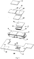
- Fig. 2 illustrates a schematic view of a dual-camera module assembly according to a first embodiment of the present disclosure
- Fig. 3 illustrates an exploded view of the dual-camera module assembly of Fig. 2
- a dual-camera module assembly 200 includes a first FPC 21, a second FPC 22, and a first camera module 23 and a second camera module 24 juxtaposed with the first camera module.
- the first FPC 21 includes a first body 211 and a first connecting end 212 extending from the first body 211.
- the first connecting end 212 extends from the first body 211 along a second direction.
- the second direction in the present disclosure refers to a direction perpendicular to an arrangement direction of the first camera module 23 and the second camera module 24.
- the first body 211 is electrically connected to a bottom of the first camera module 23, and the first connecting end 212 is connected to a main circuit board 28 of the mobile terminal.
- the second FPC 22 includes a second body 221, and an extension portion 222 and a second connecting end 223 sequentially extending from the second body 221.
- the extension portion 222 and the second connecting end 223 extend from the second body 221 sequentially along a first direction.
- the first direction in the present disclosure refers to a direction parallel to the arrangement direction of the first camera module 23 and the second camera module 24.
- the second body 221 is electrically connected to a bottom of the second camera module 24.
- the extension portion 222 and the first body 211 are arranged in the superposition manner. In other words, the extension portion 222 covers the first body 211.
- the second connecting end 223 is connected to the main circuit board 28 of the mobile terminal.
- the main circuit board 28 is provided with an antenna clearance zone 283.
- the second camera module is arranged more adjacent to the antenna clearance zone 283 compared with the first camera module 23. Distances from the first connecting end 212 and distances from the second connecting end 223 to the antenna clearance zone 283 of the main circuit board 28 are greater than or equal to a predetermined value.
- the predetermined value in the present disclosure refers to a minimum distance from the first connecting end 212 to the antenna clearance zone 283 of the main circuit board 28 in this embodiment.
- the first connecting end 212 extends from the first body 211 of the first FPC 21 along the second direction; the extension portion 222 and the second connecting end 223 extend from the second body 221 of the second FPC 22 along the first direction, and the extension portion 222 and the first body 211 are arranged in the superposition manner, such that the second connecting end 223 avoids the antenna clearance zone 283.
- a smallest one of the distances from the first connecting end 212 to the antenna clearance zone 283 of the main circuit board 28 and the distances from the second connecting end 223 to the antenna clearance zone 283 is greater than or equal to the predetermined value, thereby reducing interference of the dual-camera module assembly 200 on an antenna.
- the first connecting end 212 is provided with a first connector 213, and the second connecting end 223 is provided with a second connector 224.
- the main circuit board 28 of the mobile terminal is provided with a first slot 281 and a second slot 282.
- the first connector 213 is configured to be connected to the first slot 281 in the main circuit board 28 of the mobile terminal;
- the second connector 224 is configured to be connected to the second slot 282 in the main circuit board 28 of the mobile terminal.
- the first connector 213 and the second connector 224 are configured as board to board (BTB) connectors.
- the dual-camera module assembly 200 further includes a reinforcement board 25.
- the reinforcement board 25 is provided to a side of the second body 221 away from the second camera module 24, that is, the reinforcement board 25 covers a surface of the second body 221.
- the second body 221 is located between the reinforcement board 25 and the second camera module 24. Since the second FPC 22 is larger in dimension than the first FPC 21, the second FPC 22 is subject to greater stress during installation.
- the reinforcement board 25 provided on the second body 221 can enhance structural strength of the second FPC 22.
- the dual-camera module assembly 200 further includes a mounting rack 26.
- the first camera module 23 and the second camera module 24 are mounted to the mounting rack 26, and the mounting rack 26 is fixedly connected to the main circuit board 28 of the mobile terminal.
- the mounting rack 26 is made of a metal material. In other embodiments of the present disclosure, the mounting rack 26 can employ other materials with high structural strength.
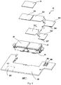
- Fig. 4 illustrates an exploded view of a dual-camera module assembly 200' according to a second embodiment of the present disclosure.
- the second embodiment of the present disclosure differs from the first embodiment in that a second connecting end 223' extends from an extension portion 222' of a second FPC 22' along the second direction, i.e. the second FPC 22' is substantially L-shaped.
- the extension portion 222' and the first connecting end 212 are arranged in a parallel and staggered manner.
- the first connecting end extends from the first body of the first FPC along the second direction; the second connecting end extends from the extension portion along the second direction.
- the smallest one of the distances from the first connecting end to the antenna clearance zone of the main circuit board and the distances from the second connecting end to the antenna clearance zone is equal to the predetermined value, thereby reducing the interference of the dual-camera module assembly on the antenna.
- Fig. 5 illustrates an exploded view of a dual-camera module assembly 200" according to a third embodiment of the present disclosure.
- the third embodiment of the present disclosure differs from the first embodiment in that a first connecting end 212' extends from a first body 211' of a first FPC 21' along the first direction.
- the second connecting end 223' extends from the extension portion 222' along the second direction. That is, the second FPC 22' is substantially L-shaped.
- the first connecting end extends from the first body of the first FPC along the first direction; the second connecting end extends from the extension portion along the second direction, and the extension portion and the first body are arranged in the superposition manner, such that the second connecting end avoids the antenna clearance zone.
- the smallest one of the distances from the first connecting end to the antenna clearance zone of the main circuit board and the distances from the second connecting end to the antenna clearance zone is larger than or equal to the predetermined value, thereby reducing the interference of the dual-camera module assembly on the antenna.
- Fig. 6 illustrates an exploded view of a dual-camera module assembly 200'" according to a fourth embodiment of the present disclosure.
- the fourth embodiment of the present disclosure differs from the first embodiment in that the first connecting end 212' extends from the first body 211' along the first direction.
- the extension portion 222 of the second FPC 22 and the first connecting end 212' are arranged in a parallel and staggered manner.
- the first connecting end extends from the first body of the first FPC along the first direction; the extension portion and the second connecting end extend sequentially from the second FPC along the first direction.
- the smallest one of the distances from the first connecting end to the antenna clearance zone of the main circuit board and the distances from the second connecting end to the antenna clearance zone is greater than the predetermined value, thereby reducing the interference of the dual-camera module assembly on the antenna.
- FIG. 7 is a block diagram of a structure of a mobile terminal according to an embodiment of the present disclosure.
- a mobile terminal 500 includes a dual-camera module assembly 200 and a main circuit board 28. It could be understood that the dual-camera module assembly 200 is the dual-camera module assembly according to any one of the above embodiments, and the main circuit board 28 is the main circuit board according to any one of the above embodiments.
- the main circuit board 28 is provided with the antenna clearance zone.
- the second camera module is arranged more adjacent to the antenna clearance zone compared with the first camera module.
- the dual-camera module assembly 200 is electrically connected with the main circuit board 28. Further specifically, the main circuit board can be a PCB or FPC.
- the mobile terminal according to the present disclosure can be a mobile phone, a tablet computer, a television, a monitor, a laptop, a digital photo frame, a navigator, etc.
Landscapes
- Engineering & Computer Science (AREA)
- Signal Processing (AREA)
- Microelectronics & Electronic Packaging (AREA)
- Multimedia (AREA)
- Human Computer Interaction (AREA)
- Physics & Mathematics (AREA)
- Electromagnetism (AREA)
- Telephone Set Structure (AREA)
- Studio Devices (AREA)
Claims (13)
- Doppelkameramodulanordnung (200, 200', 200", 200'") für ein mobiles Endgerät, wobei die Doppelkameramodulanordnung (200, 200', 200", 200'") eine erste flexible Leiterplatte (21, 21'), eine zweite flexible Leiterplatte (22, 22') und ein erstes Kameramodul (23) und ein neben dem ersten Kameramodul (23) angeordnetes zweites Kameramodul (24) umfasst, wobei die erste flexible Leiterplatte (21, 21') einen ersten Körper (211, 211') und ein erstes Verbindungsende (212) aufweist, das sich von dem ersten Körper (211, 211 ') weg erstreckt, wobei der erste Körper (211, 211') mit dem ersten Kameramodul (23) verbunden ist und das erste Verbindungsende (212) zur Verbindung mit einer Hauptplatine (28) des mobilen Endgerätes ausgebildet ist; dadurch gekennzeichnet, dass die zweite flexible Leiterplatte (22, 22') einen zweiten Körper (221, 221') und einen Verlängerungsabschnitt (222, 222') und ein zweites Verbindungsende (223, 223') umfasst, wobei sich der Verlängerungsabschnitt (222, 222') und das zweite Verbindungsende (223, 223') aufeinanderfolgend von dem zweiten Körper weg erstrecken (221, 221'), wobei der zweite Körper (221, 221') mit dem zweiten Kameramodul (24) verbunden ist, wobei der Verlängerungsabschnitt (222, 222') und der erste Körper (211,211') übereinander angeordnet sind und wobei das zweite Verbindungsende (223, 223') zur Verbindung mit der Hauptplatine (28) des mobilen Endgerätes ausgebildet ist; und das erste Verbindungsende (212, 212') und das zweite Verbindungsende (223, 223') derart ausgebildet sind, dass ein kleinster Abstand von Abständen, umfassend Abstände von dem ersten Verbindungsende (212, 212') zu einem Antennenfreiraum (283) der Hauptplatine (28) und von dem zweiten Verbindungende (223, 223') zu dem Antennenfreiraum (283) größer oder gleich einem vorbestimmten Wert ist.
- Doppelkameramodulanordnung (200) nach Anspruch 1, dadurch gekennzeichnet, dass der Verlängerungsabschnitt (222) und das zweite Verbindungsende (223) sich von dem zweiten Körper (221) aufeinanderfolgend entlang einer ersten Richtung weg erstrecken, wobei sich die erste Richtung auf eine Richtung parallel zu einer Anordnungsrichtung des ersten Kameramoduls (23) und des zweiten Kameramoduls (24) bezieht; und sich das erste Verbindungsende (212) von dem ersten Körper (211) entlang einer zweiten Richtung weg erstreckt, wobei sich die zweite Richtung auf eine zu der Anordnungsrichtung des ersten Kameramoduls (23) und des zweiten Kameramoduls (24) rechtwinklige Richtung bezieht.
- Doppelkameramodulanordnung (200") nach Anspruch 1, dadurch gekennzeichnet, dass sich das erste Verbindungsende (212') von dem ersten Körper (211') entlang einer ersten Richtung erstreckt, wobei sich die erste Richtung auf eine Richtung parallel zu einer Anordnungsrichtung des ersten Kameramoduls (23) und des zweiten Kameramoduls (24) bezieht; und sich das zweite Verbindungsende (223') von dem Verlängerungsabschnitt (222') entlang einer zweiten Richtung erstreckt, wobei sich die zweite Richtung auf eine zu der Anordnungsrichtung des ersten Kameramoduls (23) und des zweiten Kameramoduls (24) rechtwinklige Richtung bezieht.
- Doppelkameramodulanordnung (200"') nach Anspruch 1, dadurch gekennzeichnet, dass der Verlängerungsabschnitt (222) und das erste Verbindungsende (212') parallel und gestuft angeordnet sind und der Verlängerungsabschnitt (222) und das zweite Verbindungsende (223) sich von dem zweiten Körper (221) aus aufeinanderfolgend entlang einer ersten Richtung weg erstrecken, wobei sich die erste Richtung auf eine Richtung parallel zu einer Anordnungsrichtung des ersten Kameramoduls (23) und des zweiten Kameramoduls (24) bezieht.
- Doppelkameramodulanordnung (200') nach Anspruch 1, dadurch gekennzeichnet, dass der Verlängerungsabschnitt (222') und das erste Verbindungsende (212) parallel und gestuft angeordnet sind und das zweite Verbindungsende (223') sich von dem Verlängerungsabschnitt (222') entlang einer zweiten Richtung weg erstreckt, wobei sich die zweite Richtung auf eine zu einer Anordnungsrichtung des ersten Kameramoduls (23) und des zweiten Kameramoduls (24) rechtwinklige Richtung bezieht.
- Doppelkameramodulanordnung (200, 200') nach Anspruch 2 oder 5, dadurch gekennzeichnet, dass das erste Verbindungsende (212) so ausgebildet ist, dass ein Mindestabstand von dem ersten Verbindungsende (212) zu dem Antennenfreiraum (283) der Hauptplatine (28) gleich dem vorbestimmten Wert ist.
- Doppelkameramodulanordnung (200, 200', 200", 200'") nach einem der Ansprüche 1 bis 5, dadurch gekennzeichnet, dass die Doppelkameramodulanordnung (200, 200', 200", 200'") des Weiteren eine Verstärkungsplatte umfasst und die Verstärkungsplatte an einer von dem zweiten Kameramodul (24) abgewandten Seite des zweiten Körpers (221, 221') vorgesehen ist.
- Doppelkameramodulanordnung (200, 200', 200'', 200"') nach einem der Ansprüche 1 bis 5, dadurch gekennzeichnet, dass das erste Verbindungsende (212, 212') mit einem ersten Verbindungselement (213) versehen ist, das zweite Verbindungsende (223, 223') mit einem zweiten Verbindungselement (224) versehen ist, das erste Verbindungselement (213) zur Verbindung mit einem ersten Steckplatz (281) in der Hauptplatine (28) des mobilen Endgeräts ausgebildet ist und das zweite Verbindungselement (224) zur Verbindung mit einem zweiten Steckplatz (282) in der Hauptplatine (28) des mobilen Endgeräts ausgebildet ist.
- Doppelkameramodulanordnung (200, 200', 200", 200'") nach einem der Ansprüche 1 bis 5, dadurch gekennzeichnet, dass die Doppelkameramodulanordnung (200, 200', 200", 200"') des Weiteren einen Montagerahmen aufweist, das erste Kameramodul (23) und das zweite Kameramodul (24) an dem Montagegerahmen montiert sind und das Montagegestell zur festen Verbindung mit der Hauptplatine (28) des mobilen Endgerätes ausgebildet ist.
- Doppelkameramodulanordnung (200, 200', 200", 200'") nach einem der Ansprüche 1 bis 5, dadurch gekennzeichnet, dass der Verlängerungsabschnitt (222, 222') über dem ersten Körper (211,211') angeordnet ist.
- Mobiles Endgerät, dadurch gekennzeichnet, dass das mobile Endgerät eine Doppelkameramodulanordnung (200, 200', 200", 200''') nach einem der Ansprüche 1 bis 10 und eine Hauptplatine (28) umfasst, wobei die Hauptplatine (28) mit einem Antennenfreiraum (283) versehen ist.
- Mobiles Endgerät nach Anspruch 11, dadurch gekennzeichnet, dass die Doppelkameramodulanordnung (200, 200', 200", 200''') mit der Hauptplatine (28) elektrisch verbunden ist.
- Mobiles Endgerät nach Anspruch 11 oder 12, dadurch gekennzeichnet, dass die Hauptplatine (28) eine Leiterplatte sein kann.
Applications Claiming Priority (1)
| Application Number | Priority Date | Filing Date | Title |
|---|---|---|---|
| CN201621401972.2U CN206294253U (zh) | 2016-12-20 | 2016-12-20 | 双摄像头模组及移动终端 |
Publications (2)
| Publication Number | Publication Date |
|---|---|
| EP3340586A1 EP3340586A1 (de) | 2018-06-27 |
| EP3340586B1 true EP3340586B1 (de) | 2019-02-20 |
Family
ID=59104370
Family Applications (1)
| Application Number | Title | Priority Date | Filing Date |
|---|---|---|---|
| EP17203534.7A Active EP3340586B1 (de) | 2016-12-20 | 2017-11-24 | Doppelkameramodulanordnung und mobiles endgerät |
Country Status (5)
| Country | Link |
|---|---|
| US (1) | US10291834B2 (de) |
| EP (1) | EP3340586B1 (de) |
| CN (1) | CN206294253U (de) |
| ES (1) | ES2724473T3 (de) |
| WO (1) | WO2018113170A1 (de) |
Families Citing this family (12)
| Publication number | Priority date | Publication date | Assignee | Title |
|---|---|---|---|---|
| CN106791330B (zh) * | 2017-01-11 | 2019-08-13 | Oppo广东移动通信有限公司 | 摄像头模组及终端 |
| CN107580168B (zh) * | 2017-10-24 | 2019-10-25 | Oppo广东移动通信有限公司 | 摄像头模组、电路板组件及移动终端 |
| CN108024038B (zh) * | 2017-11-29 | 2020-01-17 | Oppo广东移动通信有限公司 | 终端设备及其摄像头组件 |
| CN110313170B (zh) * | 2018-01-19 | 2021-08-31 | 深圳市大疆创新科技有限公司 | 视觉模组集成模块与无人机 |
| CN108448230B (zh) * | 2018-01-25 | 2020-12-15 | 瑞声科技(南京)有限公司 | 天线系统及通讯终端 |
| CN111050030A (zh) * | 2018-10-12 | 2020-04-21 | 艾沙技术有限公司 | 一种相机模块及其制造方法 |
| CN109587382B (zh) * | 2018-12-18 | 2024-09-27 | 青岛小鸟看看科技有限公司 | 相机模组以及一种深度相机 |
| KR102805299B1 (ko) * | 2019-07-26 | 2025-05-12 | 삼성전자주식회사 | 전자 부품 어셈블리를 포함하는 전자 장치 |
| TWI708135B (zh) * | 2020-04-21 | 2020-10-21 | 華碩電腦股份有限公司 | 電子裝置及其功能模組 |
| TWM600509U (zh) * | 2020-05-12 | 2020-08-21 | 華碩電腦股份有限公司 | 電子裝置 |
| CN113726988A (zh) * | 2020-05-26 | 2021-11-30 | 黑芝麻智能科技(重庆)有限公司 | 对准偏移减少系统 |
| CN114500697B (zh) | 2021-07-16 | 2023-01-03 | 荣耀终端有限公司 | 电子设备 |
Family Cites Families (15)
| Publication number | Priority date | Publication date | Assignee | Title |
|---|---|---|---|---|
| JP2010251375A (ja) | 2009-04-10 | 2010-11-04 | Toshiba Corp | 電子回路 |
| CN101877731B (zh) * | 2009-04-30 | 2013-10-09 | 深圳富泰宏精密工业有限公司 | 摄像装置及具有该摄像装置的便携式电子装置 |
| CN102762069A (zh) * | 2012-07-24 | 2012-10-31 | 鸿富锦精密工业(深圳)有限公司 | 电子装置 |
| KR102025706B1 (ko) * | 2013-01-30 | 2019-09-26 | 삼성전자주식회사 | 휴대용 단말기의 안테나 장치 |
| CN103973943A (zh) * | 2013-01-31 | 2014-08-06 | 鸿富锦精密工业(深圳)有限公司 | 双摄像头模组 |
| CN104717325A (zh) * | 2013-12-12 | 2015-06-17 | 中兴通讯股份有限公司 | 一种电子设备 |
| CN204305162U (zh) * | 2014-11-28 | 2015-04-29 | 广东欧珀移动通信有限公司 | 双摄像头装置及其终端设备 |
| CN204305161U (zh) * | 2014-11-28 | 2015-04-29 | 广东欧珀移动通信有限公司 | 双摄像头装置及其终端设备 |
| CN104333687B (zh) * | 2014-11-28 | 2017-12-19 | 广东欧珀移动通信有限公司 | 双摄像头装置及其终端设备 |
| CN204305163U (zh) * | 2014-11-28 | 2015-04-29 | 广东欧珀移动通信有限公司 | 双摄像头装置及其终端设备 |
| KR101914894B1 (ko) * | 2015-04-02 | 2018-11-02 | 코어포토닉스 리미티드 | 듀얼 광학 모듈 카메라의 듀얼 보이스 코일 모터 구조체 |
| US9973669B2 (en) * | 2015-08-28 | 2018-05-15 | Apple Inc. | Dual overmolded reconstructed camera module |
| TWI656830B (zh) * | 2015-12-31 | 2019-04-11 | 鴻海精密工業股份有限公司 | 通信裝置 |
| CN205545547U (zh) | 2016-03-03 | 2016-08-31 | 南昌欧菲光电技术有限公司 | 成像模组及电子装置 |
| EP3429181B1 (de) * | 2016-03-12 | 2024-10-16 | Ningbo Sunny Opotech Co., Ltd. | Arraykameramodul, geformte lichtempfindliche anordnung und herstellungsverfahren dafür sowie elektronische vorrichtung |
-
2016
- 2016-12-20 CN CN201621401972.2U patent/CN206294253U/zh not_active Expired - Fee Related
-
2017
- 2017-05-11 WO PCT/CN2017/083956 patent/WO2018113170A1/zh not_active Ceased
- 2017-11-17 US US15/816,394 patent/US10291834B2/en active Active
- 2017-11-24 EP EP17203534.7A patent/EP3340586B1/de active Active
- 2017-11-24 ES ES17203534T patent/ES2724473T3/es active Active
Non-Patent Citations (1)
| Title |
|---|
| None * |
Also Published As
| Publication number | Publication date |
|---|---|
| EP3340586A1 (de) | 2018-06-27 |
| US20180176435A1 (en) | 2018-06-21 |
| US10291834B2 (en) | 2019-05-14 |
| WO2018113170A1 (zh) | 2018-06-28 |
| ES2724473T3 (es) | 2019-09-11 |
| CN206294253U (zh) | 2017-06-30 |
Similar Documents
| Publication | Publication Date | Title |
|---|---|---|
| EP3340586B1 (de) | Doppelkameramodulanordnung und mobiles endgerät | |
| US10446985B2 (en) | Electrical connector with shield plate | |
| CN204948494U (zh) | 树脂多层基板及电子设备 | |
| CN103930309A (zh) | 用于车辆的摄像头模块 | |
| CN106713540B (zh) | 双摄像头模组及移动终端 | |
| EP3771194B1 (de) | Kameramodul und mobiles terminal | |
| KR102941572B1 (ko) | 경연성 인쇄회로기판 및 그를 포함하는 전자 장치 | |
| US20170070008A1 (en) | Connector socket and connector | |
| JP5733456B1 (ja) | 基板接続用コネクタ | |
| EP2876873A1 (de) | Teilerdung, elektronische Vorrichtung, Bildgebungsvorrichtung und Erdungsteilherstellungsverfahren | |
| US11147155B2 (en) | Electronic apparatus equipped with flexible boards | |
| WO2022268017A1 (zh) | 电子设备 | |
| EP3285117B1 (de) | Leiterplattenanordnung und endgerät | |
| CN211655064U (zh) | 后壳及电子设备 | |
| US12562462B2 (en) | Electronic assembly and electronic device | |
| EP3082330A1 (de) | Hauptplatinenstruktur und endgerät | |
| US11256057B2 (en) | Lens module with electromagnetic prothction and electronic device using the same | |
| CN107836105B (zh) | 移动终端 | |
| CN108258395A (zh) | 天线组件、中框组件及电子设备 | |
| JP2012227743A (ja) | 携帯無線機 | |
| CN108683829B (zh) | 摄像头模组、主板及移动终端 | |
| CN219164811U (zh) | 电路板组件及电子设备 | |
| CN108321508A (zh) | 天线组件及电子设备 | |
| JP2013026076A (ja) | ワイヤーハーネスとコネクタ及びそれらを用いた電子機器。 | |
| KR101149446B1 (ko) | 인쇄회로기판 및 이를 구비하는 카메라 모듈 |
Legal Events
| Date | Code | Title | Description |
|---|---|---|---|
| PUAI | Public reference made under article 153(3) epc to a published international application that has entered the european phase |
Free format text: ORIGINAL CODE: 0009012 |
|
| STAA | Information on the status of an ep patent application or granted ep patent |
Free format text: STATUS: REQUEST FOR EXAMINATION WAS MADE |
|
| 17P | Request for examination filed |
Effective date: 20180515 |
|
| AK | Designated contracting states |
Kind code of ref document: A1 Designated state(s): AL AT BE BG CH CY CZ DE DK EE ES FI FR GB GR HR HU IE IS IT LI LT LU LV MC MK MT NL NO PL PT RO RS SE SI SK SM TR |
|
| AX | Request for extension of the european patent |
Extension state: BA ME |
|
| GRAP | Despatch of communication of intention to grant a patent |
Free format text: ORIGINAL CODE: EPIDOSNIGR1 |
|
| STAA | Information on the status of an ep patent application or granted ep patent |
Free format text: STATUS: GRANT OF PATENT IS INTENDED |
|
| INTG | Intention to grant announced |
Effective date: 20180928 |
|
| GRAS | Grant fee paid |
Free format text: ORIGINAL CODE: EPIDOSNIGR3 |
|
| GRAA | (expected) grant |
Free format text: ORIGINAL CODE: 0009210 |
|
| STAA | Information on the status of an ep patent application or granted ep patent |
Free format text: STATUS: THE PATENT HAS BEEN GRANTED |
|
| AK | Designated contracting states |
Kind code of ref document: B1 Designated state(s): AL AT BE BG CH CY CZ DE DK EE ES FI FR GB GR HR HU IE IS IT LI LT LU LV MC MK MT NL NO PL PT RO RS SE SI SK SM TR |
|
| REG | Reference to a national code |
Ref country code: GB Ref legal event code: FG4D |
|
| REG | Reference to a national code |
Ref country code: CH Ref legal event code: EP |
|
| REG | Reference to a national code |
Ref country code: AT Ref legal event code: REF Ref document number: 1099741 Country of ref document: AT Kind code of ref document: T Effective date: 20190315 |
|
| REG | Reference to a national code |
Ref country code: IE Ref legal event code: FG4D |
|
| REG | Reference to a national code |
Ref country code: DE Ref legal event code: R096 Ref document number: 602017002233 Country of ref document: DE |
|
| REG | Reference to a national code |
Ref country code: NL Ref legal event code: FP |
|
| REG | Reference to a national code |
Ref country code: LT Ref legal event code: MG4D |
|
| PG25 | Lapsed in a contracting state [announced via postgrant information from national office to epo] |
Ref country code: LT Free format text: LAPSE BECAUSE OF FAILURE TO SUBMIT A TRANSLATION OF THE DESCRIPTION OR TO PAY THE FEE WITHIN THE PRESCRIBED TIME-LIMIT Effective date: 20190220 Ref country code: PT Free format text: LAPSE BECAUSE OF FAILURE TO SUBMIT A TRANSLATION OF THE DESCRIPTION OR TO PAY THE FEE WITHIN THE PRESCRIBED TIME-LIMIT Effective date: 20190620 Ref country code: NO Free format text: LAPSE BECAUSE OF FAILURE TO SUBMIT A TRANSLATION OF THE DESCRIPTION OR TO PAY THE FEE WITHIN THE PRESCRIBED TIME-LIMIT Effective date: 20190520 Ref country code: SE Free format text: LAPSE BECAUSE OF FAILURE TO SUBMIT A TRANSLATION OF THE DESCRIPTION OR TO PAY THE FEE WITHIN THE PRESCRIBED TIME-LIMIT Effective date: 20190220 Ref country code: FI Free format text: LAPSE BECAUSE OF FAILURE TO SUBMIT A TRANSLATION OF THE DESCRIPTION OR TO PAY THE FEE WITHIN THE PRESCRIBED TIME-LIMIT Effective date: 20190220 |
|
| PG25 | Lapsed in a contracting state [announced via postgrant information from national office to epo] |
Ref country code: LV Free format text: LAPSE BECAUSE OF FAILURE TO SUBMIT A TRANSLATION OF THE DESCRIPTION OR TO PAY THE FEE WITHIN THE PRESCRIBED TIME-LIMIT Effective date: 20190220 Ref country code: GR Free format text: LAPSE BECAUSE OF FAILURE TO SUBMIT A TRANSLATION OF THE DESCRIPTION OR TO PAY THE FEE WITHIN THE PRESCRIBED TIME-LIMIT Effective date: 20190521 Ref country code: RS Free format text: LAPSE BECAUSE OF FAILURE TO SUBMIT A TRANSLATION OF THE DESCRIPTION OR TO PAY THE FEE WITHIN THE PRESCRIBED TIME-LIMIT Effective date: 20190220 Ref country code: BG Free format text: LAPSE BECAUSE OF FAILURE TO SUBMIT A TRANSLATION OF THE DESCRIPTION OR TO PAY THE FEE WITHIN THE PRESCRIBED TIME-LIMIT Effective date: 20190520 Ref country code: HR Free format text: LAPSE BECAUSE OF FAILURE TO SUBMIT A TRANSLATION OF THE DESCRIPTION OR TO PAY THE FEE WITHIN THE PRESCRIBED TIME-LIMIT Effective date: 20190220 Ref country code: IS Free format text: LAPSE BECAUSE OF FAILURE TO SUBMIT A TRANSLATION OF THE DESCRIPTION OR TO PAY THE FEE WITHIN THE PRESCRIBED TIME-LIMIT Effective date: 20190620 |
|
| REG | Reference to a national code |
Ref country code: ES Ref legal event code: FG2A Ref document number: 2724473 Country of ref document: ES Kind code of ref document: T3 Effective date: 20190911 |
|
| REG | Reference to a national code |
Ref country code: AT Ref legal event code: MK05 Ref document number: 1099741 Country of ref document: AT Kind code of ref document: T Effective date: 20190220 |
|
| PG25 | Lapsed in a contracting state [announced via postgrant information from national office to epo] |
Ref country code: EE Free format text: LAPSE BECAUSE OF FAILURE TO SUBMIT A TRANSLATION OF THE DESCRIPTION OR TO PAY THE FEE WITHIN THE PRESCRIBED TIME-LIMIT Effective date: 20190220 Ref country code: CZ Free format text: LAPSE BECAUSE OF FAILURE TO SUBMIT A TRANSLATION OF THE DESCRIPTION OR TO PAY THE FEE WITHIN THE PRESCRIBED TIME-LIMIT Effective date: 20190220 Ref country code: RO Free format text: LAPSE BECAUSE OF FAILURE TO SUBMIT A TRANSLATION OF THE DESCRIPTION OR TO PAY THE FEE WITHIN THE PRESCRIBED TIME-LIMIT Effective date: 20190220 Ref country code: DK Free format text: LAPSE BECAUSE OF FAILURE TO SUBMIT A TRANSLATION OF THE DESCRIPTION OR TO PAY THE FEE WITHIN THE PRESCRIBED TIME-LIMIT Effective date: 20190220 Ref country code: AL Free format text: LAPSE BECAUSE OF FAILURE TO SUBMIT A TRANSLATION OF THE DESCRIPTION OR TO PAY THE FEE WITHIN THE PRESCRIBED TIME-LIMIT Effective date: 20190220 Ref country code: SK Free format text: LAPSE BECAUSE OF FAILURE TO SUBMIT A TRANSLATION OF THE DESCRIPTION OR TO PAY THE FEE WITHIN THE PRESCRIBED TIME-LIMIT Effective date: 20190220 |
|
| REG | Reference to a national code |
Ref country code: DE Ref legal event code: R097 Ref document number: 602017002233 Country of ref document: DE |
|
| PG25 | Lapsed in a contracting state [announced via postgrant information from national office to epo] |
Ref country code: PL Free format text: LAPSE BECAUSE OF FAILURE TO SUBMIT A TRANSLATION OF THE DESCRIPTION OR TO PAY THE FEE WITHIN THE PRESCRIBED TIME-LIMIT Effective date: 20190220 Ref country code: SM Free format text: LAPSE BECAUSE OF FAILURE TO SUBMIT A TRANSLATION OF THE DESCRIPTION OR TO PAY THE FEE WITHIN THE PRESCRIBED TIME-LIMIT Effective date: 20190220 |
|
| RAP2 | Party data changed (patent owner data changed or rights of a patent transferred) |
Owner name: GUANGDONG OPPO MOBILE TELECOMMUNICATIONS CORP., LT |
|
| PLBE | No opposition filed within time limit |
Free format text: ORIGINAL CODE: 0009261 |
|
| STAA | Information on the status of an ep patent application or granted ep patent |
Free format text: STATUS: NO OPPOSITION FILED WITHIN TIME LIMIT |
|
| PG25 | Lapsed in a contracting state [announced via postgrant information from national office to epo] |
Ref country code: AT Free format text: LAPSE BECAUSE OF FAILURE TO SUBMIT A TRANSLATION OF THE DESCRIPTION OR TO PAY THE FEE WITHIN THE PRESCRIBED TIME-LIMIT Effective date: 20190220 |
|
| 26N | No opposition filed |
Effective date: 20191121 |
|
| PG25 | Lapsed in a contracting state [announced via postgrant information from national office to epo] |
Ref country code: TR Free format text: LAPSE BECAUSE OF FAILURE TO SUBMIT A TRANSLATION OF THE DESCRIPTION OR TO PAY THE FEE WITHIN THE PRESCRIBED TIME-LIMIT Effective date: 20190220 |
|
| PG25 | Lapsed in a contracting state [announced via postgrant information from national office to epo] |
Ref country code: MC Free format text: LAPSE BECAUSE OF FAILURE TO SUBMIT A TRANSLATION OF THE DESCRIPTION OR TO PAY THE FEE WITHIN THE PRESCRIBED TIME-LIMIT Effective date: 20190220 Ref country code: LU Free format text: LAPSE BECAUSE OF NON-PAYMENT OF DUE FEES Effective date: 20191124 |
|
| REG | Reference to a national code |
Ref country code: BE Ref legal event code: MM Effective date: 20191130 |
|
| PG25 | Lapsed in a contracting state [announced via postgrant information from national office to epo] |
Ref country code: IE Free format text: LAPSE BECAUSE OF NON-PAYMENT OF DUE FEES Effective date: 20191124 |
|
| PG25 | Lapsed in a contracting state [announced via postgrant information from national office to epo] |
Ref country code: BE Free format text: LAPSE BECAUSE OF NON-PAYMENT OF DUE FEES Effective date: 20191130 |
|
| PG25 | Lapsed in a contracting state [announced via postgrant information from national office to epo] |
Ref country code: CY Free format text: LAPSE BECAUSE OF FAILURE TO SUBMIT A TRANSLATION OF THE DESCRIPTION OR TO PAY THE FEE WITHIN THE PRESCRIBED TIME-LIMIT Effective date: 20190220 |
|
| REG | Reference to a national code |
Ref country code: CH Ref legal event code: PL |
|
| PG25 | Lapsed in a contracting state [announced via postgrant information from national office to epo] |
Ref country code: HU Free format text: LAPSE BECAUSE OF FAILURE TO SUBMIT A TRANSLATION OF THE DESCRIPTION OR TO PAY THE FEE WITHIN THE PRESCRIBED TIME-LIMIT; INVALID AB INITIO Effective date: 20171124 Ref country code: MT Free format text: LAPSE BECAUSE OF FAILURE TO SUBMIT A TRANSLATION OF THE DESCRIPTION OR TO PAY THE FEE WITHIN THE PRESCRIBED TIME-LIMIT Effective date: 20190220 |
|
| PG25 | Lapsed in a contracting state [announced via postgrant information from national office to epo] |
Ref country code: CH Free format text: LAPSE BECAUSE OF NON-PAYMENT OF DUE FEES Effective date: 20201130 Ref country code: LI Free format text: LAPSE BECAUSE OF NON-PAYMENT OF DUE FEES Effective date: 20201130 |
|
| PG25 | Lapsed in a contracting state [announced via postgrant information from national office to epo] |
Ref country code: SI Free format text: LAPSE BECAUSE OF FAILURE TO SUBMIT A TRANSLATION OF THE DESCRIPTION OR TO PAY THE FEE WITHIN THE PRESCRIBED TIME-LIMIT Effective date: 20190220 |
|
| PG25 | Lapsed in a contracting state [announced via postgrant information from national office to epo] |
Ref country code: MK Free format text: LAPSE BECAUSE OF FAILURE TO SUBMIT A TRANSLATION OF THE DESCRIPTION OR TO PAY THE FEE WITHIN THE PRESCRIBED TIME-LIMIT Effective date: 20190220 |
|
| P01 | Opt-out of the competence of the unified patent court (upc) registered |
Effective date: 20230412 |
|
| PGFP | Annual fee paid to national office [announced via postgrant information from national office to epo] |
Ref country code: NL Payment date: 20251127 Year of fee payment: 9 |
|
| PGFP | Annual fee paid to national office [announced via postgrant information from national office to epo] |
Ref country code: DE Payment date: 20251124 Year of fee payment: 9 |
|
| PGFP | Annual fee paid to national office [announced via postgrant information from national office to epo] |
Ref country code: GB Payment date: 20251126 Year of fee payment: 9 |
|
| PGFP | Annual fee paid to national office [announced via postgrant information from national office to epo] |
Ref country code: IT Payment date: 20251120 Year of fee payment: 9 |
|
| PGFP | Annual fee paid to national office [announced via postgrant information from national office to epo] |
Ref country code: FR Payment date: 20251126 Year of fee payment: 9 |
|
| PGFP | Annual fee paid to national office [announced via postgrant information from national office to epo] |
Ref country code: ES Payment date: 20251202 Year of fee payment: 9 |