EP3339131A1 - Zugverband mit mindestens einer aufhängungsvorrichtung - Google Patents
Zugverband mit mindestens einer aufhängungsvorrichtung Download PDFInfo
- Publication number
- EP3339131A1 EP3339131A1 EP17202573.6A EP17202573A EP3339131A1 EP 3339131 A1 EP3339131 A1 EP 3339131A1 EP 17202573 A EP17202573 A EP 17202573A EP 3339131 A1 EP3339131 A1 EP 3339131A1
- Authority
- EP
- European Patent Office
- Prior art keywords
- suspension device
- voltage cable
- high voltage
- holder
- cable section
- Prior art date
- Legal status (The legal status is an assumption and is not a legal conclusion. Google has not performed a legal analysis and makes no representation as to the accuracy of the status listed.)
- Granted
Links
Images


Classifications
-
- B—PERFORMING OPERATIONS; TRANSPORTING
- B61—RAILWAYS
- B61G—COUPLINGS; DRAUGHT AND BUFFING APPLIANCES
- B61G5/00—Couplings for special purposes not otherwise provided for
- B61G5/06—Couplings for special purposes not otherwise provided for for, or combined with, couplings or connectors for fluid conduits or electric cables
- B61G5/10—Couplings for special purposes not otherwise provided for for, or combined with, couplings or connectors for fluid conduits or electric cables for electric cables
-
- B—PERFORMING OPERATIONS; TRANSPORTING
- B61—RAILWAYS
- B61G—COUPLINGS; DRAUGHT AND BUFFING APPLIANCES
- B61G5/00—Couplings for special purposes not otherwise provided for
- B61G5/06—Couplings for special purposes not otherwise provided for for, or combined with, couplings or connectors for fluid conduits or electric cables
- B61G5/08—Couplings for special purposes not otherwise provided for for, or combined with, couplings or connectors for fluid conduits or electric cables for fluid conduits
Definitions
- the invention relates to a train with at least one suspension device to which at least one high voltage cable section is suspended.
- a train In the field of rail vehicle technology, it is known that a train can have two pantographs. These can each be arranged on a final carriage of the train. For reasons of redundancy, a high-voltage line then connects the two current collectors by means of high-voltage lines and so-called jumpers, i. Cable bridges between the car transitions. The high voltage line also runs through disconnectors and main transformers.
- the publication EP 1 415 883 B1 describes a junction box to which electrical cables are connected.
- electrical lines In the interior of the junction box electrical lines are housed, connect the both sides of the junction box connected electrical cable with each other.
- the junction box is attached to an intermediate coupling of a drawstring.
- the disadvantage here is that the construction cost and weight are very high.
- unfavorable bending radii result in the area of the connections on the connection box when the train is traveling through curves. This can cause cable wear in the area of the connections on the junction box.
- the publication FR 2 713 183 B1 discloses a train assembly in which a cable transition for power lines in the roof area between two cars is arranged.
- the cable transition is attached to a telescopic pole.
- cornering shortened or extended the telescopic rod. Again, it is disadvantageous that a high construction cost is required. In addition, there is a wear in the telescopic rod.
- the publication JP 2602968 Y relates to a cable connection between two cars of a train.
- the cable connection can be arranged in the roof area or in the underframe area.
- the cable connection rests on a pulley which is attached to one of the two carriages.
- the disadvantage here is that in an addition of Dirt, ice, sand or the like between the roller and the cable connection material damage to the cable connection can be made. With electric cables, this can lead to dangerous situations.
- the invention is therefore based on the object to provide a train in which a high voltage cable connection is suspended between two cars, the high voltage cable connection in curves has favorable bending radii, a low construction cost is required and wear is avoided.
- the solution to the problem lies in a train with at least one suspension device on which at least one high-voltage cable section is suspended, wherein the train comprises at least two carriages and the suspension device receives the high-voltage cable section between two adjacent carriages of the train and each high-voltage cable section has two ends, each connected via a plug connection with a respective associated high voltage line in a respective associated carriage, wherein the suspension device is attached to a mechanical intermediate coupling between the two cars.
- the entire high voltage cable section is flexible and is movably and elastically supported on the suspension device.
- An advantage is that a flexibility of the high voltage cable section and a movable and elastic or resilient or yielding storage ensure favorable bending radii on the high voltage cable section and thus a favorable bending behavior of the entire high voltage cable section, for example when the train moves through curves and / or when changing between a compressed position and a normal position. Even if the intermediate coupling is in the compressed position or the normal position, the bending radii are favorable at the high-voltage cable section.
- the intermediate clutch may be, for example, an automatic clutch or a permanent clutch. Due to the movable and elastic mounting or suspension, the high-voltage cable section can on the suspension device, adjust each movement of the intermediate clutch and the two carriages. In addition, wear on the high voltage cable section is avoided.
- the two ends of the high-voltage cable section have plug elements, wherein the plug elements can each be plugged into an associated socket element on a respectively associated carriage, and each socket element is movably arranged on the associated carriage.
- the mobility of the socket elements further improves the bending behavior of the high voltage cable section, e.g. when cornering the train and / or a change between the normal position and the compressed position of the intermediate clutch.
- the high-voltage cable section in the entire region between the plug elements on continuous material gradients, wherein the high-voltage portion is arranged in particular in a flexible metal tube.
- the continuous course of the material avoids irregularities in the bending curve of the high-voltage channel section, which are e.g. can arise through connectors. This helps to avoid mechanical stresses in the high voltage cable section.
- the flexible metal tube may e.g. have a steel mesh. As a result, a stability of the high voltage cable section is increased.
- the high-voltage cable section can be suspended in an arcuate manner in the suspension device, wherein in particular a radius including an associated tolerance range for an arcuate suspension can be specified on the suspension device.
- the bow-shaped suspension also contributes to a favorable bending curve in the high-voltage cable section. A favorable radius on the bend can be calculated in advance.
- the suspension device may be arranged in a longitudinal direction of the intermediate clutch in a central region of the intermediate clutch and / or the suspension device may be arranged in a plane which extends transversely to the longitudinal direction of the intermediate clutch.
- the suspension in a central region of the intermediate coupling schematically ensures a symmetrical course of the high voltage cable section on both sides of the suspension device. This results in a uniform weight distribution of the high voltage cable section on both sides of the suspension device. Characterized in that the suspension device is perpendicular to the longitudinal axis of the intermediate coupling, the high voltage cable section extends in the longitudinal direction of the intermediate coupling.
- the suspension device may be releasably attached to the intermediate coupling and / or the high voltage cable section may have two predetermined sags including a respective associated tolerance range between the suspension device and each of the two carriages in a straight alignment of the rail vehicle.
- the releasability of the suspension device facilitates assembly and disassembly and allows for retrofitting existing drawstrings with the suspension device.
- the sagging of the high-voltage cable section is advantageous in order that during movements of the intermediate coupling or the two cars, e.g. When cornering, avoid mechanical stresses in the high voltage cable section.
- the suspension device comprises three arms, wherein a first arm is fixed to the intermediate coupling from below and a second arm and a third arm are directed away from the intermediate coupling and wherein the high voltage cable portion between the second arm and third Arm is stored.
- the three arms are one way for a structure of the suspension device, which requires little construction and little weight.
- the three arms can meet in a central region of the suspension device and / or be made in one piece. As a result, a particularly simple construction is achieved.
- an elastic element may be arranged, which carries the high-voltage cable section, wherein the elastic element in particular has a deflection with a predetermined radius including an associated tolerance range at a standstill of the drawstring.
- the elastic element contributes significantly and advantageously to the movable and resilient mounting or suspension of the high voltage cable section.
- a double holder is arranged on the elastic element, in which a first holder receives the high-voltage cable section and a second holder receives the elastic element, in particular the first holder is arranged closer to the intermediate coupling than the second holder.
- the double support is a compact component for receiving the elastic element and the high voltage cable section.
- the high-voltage cable section may be fastened to the first holder and / or the elastic element may be fastened to the second holder. This prevents the high-voltage cable section from slipping inside the first holder and from slipping the second holder relative to the elastic element.
- the first holder and / or the second holder may each be a sleeve, a rubber boot or a clamp.
- the attachment may e.g. in the case of the first holder and / or the second holder, in each case by means of an interference fit.
- first holder and the second holder may be arranged at right angles to each other and / or the first holder and the second holder may be rotatably arranged to each other. Due to the rectangular arrangement of the high voltage cable section is aligned in the direction of the longitudinal direction of the intermediate coupling. The rotation allows a more flexible yielding of the high voltage cable section.
- At least two further line sections may be fastened to the suspension device and / or to at least one additional angle element by means of at least one connecting piece, wherein the angle element may be fastened to the intermediate coupling.
- the suspension device is used simultaneously for suspension of other types of conduits, e.g. electrical cables for auxiliary equipment or hoses, e.g. for compressed air.
- the angle element improves the stability of the attachment of the connector.
- the at least one connecting piece for the further line sections may be arranged in the central region of the suspension device and / or be fastened detachably to the suspension device.
- the geometry of the suspension device is used optimally. The solvability allows easy assembly and disassembly and easy retrofitting existing train assemblies.
- the at least two cars can be double-deck cars, in particular with at least one associated passenger crossing in the upper floor.
- the invention can be used both in single-floor train assemblies and in double-deck train assemblies. In the case of double-decker trains with person transitions in the upper floor, the invention is particularly advantageous because an arrangement of a high-voltage cable section in the roof area is not permitted there for safety reasons.
- FIG. 1 and 3 show a portion of an intermediate coupling 10 of an otherwise not shown invention draw band.
- the intermediate coupling 10 itself is shown, to which a suspension device 20 for a high voltage cable section 30 is attached.
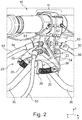
- Fig. 2 shows an enlarged section A from Fig. 1 for a portion of the suspension device 20.
- the suspension device 20 is arranged in a plane y / z that extends in a transverse direction y and a vertical direction z.
- the plane y / z is perpendicular to a longitudinal direction x of the intermediate coupling 10th
- the suspension device 20 includes a first arm 21, a second arm 22, and a third arm 23.
- the first arm 21, the second arm 22 and the third arm 23 meet at a central portion 24 and form an inverted Y-shape.
- the first arm 21 is fixed to the intermediate coupling 10 from below.
- an elastic element 25 is attached, which is designed here as a spring, in particular as a helical spring and is a possible embodiment of an elastic or resilient suspension. Other types of elastic elements are also conceivable.
- the elastic element 25 has a deflection, wherein the deflection has the radius R2 including an associated tolerance range.
- a double support 26 is centrally disposed on the elastic member 25.
- the double bracket 26 includes a first bracket 27 and a second bracket 28, each configured as a cylindrical passage. In the first holder 27 of the high voltage cable section 30 is received. In the second holder 28, the elastic element 25 is arranged. The first holder 27 is located above the second holder 28, wherein the first holder 27 is arranged perpendicular to the second holder 28.
- the first bracket 27 guides the high voltage cable portion 30 in the longitudinal direction x of the intermediate clutch 10.
- the second bracket 28 guides the elastic member 25 in the transverse direction y.
- the first holder 27 may be rotatable relative to the second holder 28.
- the double bracket 26 and the elastic member 25 may also be an elastically suspended from the intermediate coupling 10 cable clamp can be used (not shown). The cable clamp is then preferably suspended rotatably.
- the high-voltage cable section 30 has a first end 31 with a first plug element 33 and a second end 32 with a second plug element 34.
- the high voltage cable section 30 is arranged in a stainless protective hose not explicitly shown.
- a screen return is connected to the protective tube.
- the screen return and the protective hose are components of a grounding equipment.
- a first connector 41 and a second connector 42 are shown.
- the first connector 41 comprises the first connector element 33 and a first socket element 43.
- the second connector 42 comprises the second connector element 34 and a second socket element 44.
- a change in the position of the first socket element 43 and / or the second socket element 44 is possible.
- the displacement is possible in the longitudinal direction x (direction of travel) and / or in the direction opposite to the vertical direction z (downward).
- a shift of the can in the vertical direction z (up) is not possible.
- a first inclination of the first socket element 43 and a second inclination of the second socket element 44 can be changed.
- Fig. 3 is connected to the first socket element 43, a first high voltage line 45.
- a second high voltage line 46 is connected to the second socket element 44.
- the first high-voltage line 45 is arranged in a first carriage, not shown, of the drawstring.
- the second high-voltage line 46 is arranged in a second carriage, also not shown, adjacent to the first carriage.
- the high-voltage cable section 30 thus connects the first high-voltage line 45 of the first carriage to the second high-voltage line 46 of the second carriage.
- the first high voltage line 45 is arranged in a first subframe of the first carriage.
- the second high-voltage line 46 is arranged in a second subframe of the second carriage.
- the first high-voltage line 45 and the second high-voltage line 46 are arranged outside the first subframe and outside the second subframe, respectively.
- the first high-voltage line 45 and the second high-voltage line 46 are each arranged in a metal tube.
- the high voltage cable section 30 between the first connector 41 and the second connector 42 is W-shaped.
- the first connector element 33 is inclined by the angle ⁇ 1 with an associated tolerance range with respect to the longitudinal direction x.
- the second connector element 34 is inclined by the angle ⁇ 2 with an associated tolerance range with respect to the longitudinal direction x.
- the angle ⁇ 1 and the angle ⁇ 2 are equal, eg fifteen degrees.
- the high voltage cable section 30 has a predetermined radius R1 including an associated tolerance range.
- the high-voltage cable section 30 in each case has a predetermined suspension D with a respectively associated tolerance range.
- an angle member 12 is shown which is attached to the intermediate coupling 10 parallel to the suspension device 20.
- Further line sections 51, 52, 53, 54, for example of electrical lines and / or hoses, are fastened to the suspension device 20 and the angle element 12 by means of connecting pieces 61, 62, 63, 64, 65, 66 (FIG. Fig. 2 and 3 ).
- the further line section 53 is connected to the connecting piece 64 on the suspension device 20.
- the connecting piece 64 is connected to the connecting piece 65 between the suspension device 20 and the angle element 12.
- the connecting piece 65 is connected to the connecting piece 66.
- the further line section 54 is connected to the connecting piece 66.
- the further line section 51 is connected to the connecting piece 61 on the suspension device 20.
- the connecting piece 61 is connected to the connecting piece 62 between the suspension device 20 and the angle element 12.
- the connector 62 is connected to the connector 63.
- the further line section 52 is connected to the connecting piece 63.
- the high voltage cable section 30 may follow deflections of the intermediate coupling 10, avoiding mechanical stresses on the high voltage cable section 30.
- the deflections of the intermediate coupling 10 are due to deflections of the first carriage relative to the second carriage, e.g. when cornering.
- the suspension device 20, in particular the elastic element 25, and the two suspensions D cause the high-voltage cable section 30 to withstand all spatial and driving technical constraints as well as static and dynamic mechanical stresses.
- a mechanical stress of the high-voltage cable section 30 in a middle region 11 of the intermediate coupling 10 is lowest, in particular in the longitudinal direction x.
- the high-voltage cable section 30 can thus movements of the first carriage relative to the second carriage in the longitudinal direction x, the transverse direction y and the vertical direction z. as well as yield in the opposite directions.
- the angle ⁇ 1 of the first male member 33 and the angle ⁇ 2 of the second male member 34 may be varied during travel, e.g. in curves, vary since the first socket element 43 and the second socket element 44 are movable within predetermined limits.
- An arrangement of the suspension device 20 on the intermediate coupling 10 is particularly applicable to double-deck drawbars with person transitions in the upper floor.
- a suspension of the high voltage cable 30 to the intermediate coupling 10 is possible according to the embodiment, but other types of suspension are conceivable.
Landscapes
- Engineering & Computer Science (AREA)
- Mechanical Engineering (AREA)
- Electric Cable Arrangement Between Relatively Moving Parts (AREA)
Abstract
Description
- Die Erfindung betrifft einen Zugverband mit mindestens einer Aufhängungsvorrichtung, an der mindestens ein Hochspannungskabelabschnitt aufgehängt ist.
- In Bereich der Schienenfahrzeugtechnik ist es bekannt, dass ein Zugverband zwei Stromabnehmer aufweisen kann. Diese können jeweils an einem Endwagen des Zugverbandes angeordnet sein. Aus Gründen der Redundanz verbindet dann eine Hochspannungsleitung die beiden Stromabnehmer mittels Hochspannungsleitungen und sog. Jumpern, d.h. Kabelbrücken zwischen den Wagenübergängen. Die Hochspannungsleitung verläuft auch über Trennschalter und Haupttransformatoren.
- Die Druckschrift
EP 1 415 883 B1 beschreibt einen Verbindungskasten, an den elektrische Kabel angeschlossen werden. Im Innern des Verbindungskastens sind elektrische Leitungen untergebracht, die beidseitig an den Verbindungskasten angeschlossene elektrische Kabel mit einander verbinden. Der Verbindungskasten ist an einer Zwischenkupplung eines Zugverbands angebracht. Nachteilig ist hierbei, dass der Bauaufwand und das Gewicht sehr hoch sind. Au-βerdem ergeben sich bei den Kabeln außerhalb des Verbindungskastens ungünstige Biegeradien im Bereich der Anschlüsse am Verbindungskasten, wenn der Zugverband durch Kurven fährt. Dadurch kann ein Kabelverschleiß im Bereich der Anschlüsse am Verbindungskasten entstehen. - Die Druckschrift
FR 2 713 183 B1 - Die Druckschrift
JP 2602968 Y - Der Erfindung liegt daher die Aufgabe zu Grunde, einen Zugverband zu schaffen, bei dem eine Hochspannungskabelverbindung zwischen zwei Wagen aufgehängt ist, wobei die Hochspannungskabelverbindung in Kurven günstige Biegeradien aufweist, ein geringer Bauaufwand erforderlich ist und ein Verschleiß vermieden wird.
- Diese Aufgabe wird erfindungsgemäß mit einem Zugverband mit mindestens einer Aufhängungsvorrichtung nach Anspruch 1 gelöst. Vorteilhafte Ausgestaltungen der Erfindung sind in den Unteransprüchen enthalten.
- Erfindungsgemäß besteht die Lösung der Aufgabe in einem Zugverband mit mindestens einer Aufhängungsvorrichtung, an der mindestens ein Hochspannungskabelabschnitt aufgehängt ist, wobei der Zugverband mindestens zwei Wagen aufweist und die Aufhängungsvorrichtung den Hochspannungskabelabschnitt jeweils zwischen zwei benachbarten Wagen des Zugverbands aufnimmt und wobei jeder Hochspannungskabelabschnitt zwei Enden aufweist, die jeweils über eine Steckverbindung mit einer jeweils zugehörigen Hochspannungsleitung in einem jeweils zugehörigen Wagen verbunden sind, wobei die Aufhängungsvorrichtung an einer mechanischen Zwischenkupplung zwischen den zwei Wagen befestigt ist. Der gesamte Hochspannungskabelabschnitt ist biegsam und ist an der Aufhängungsvorrichtung beweglich und elastisch gelagert.
- Ein Vorteil besteht darin, dass eine Biegsamkeit des Hochspannungskabelabschnitts und eine bewegliche und elastische bzw. federnde bzw. nachgiebige Lagerung günstige Biegeradien am Hochspannungskabelabschnitt und damit ein günstiges Biegeverhalten des gesamten Hochspannungskabelabschnitts gewährleisten, z.B. wenn der Zugverband durch Kurven fährt und/oder bei einem Wechsel zwischen einer gestauchten Position und einer Normalposition. Auch wenn sich die Zwischenkupplung in der gestauchten Position oder der Normalposition befindet, sind die Biegeradien am Hochspannungskabelabschnitt günstig. Die Zwischenkupplung kann z.B. eine automatische Kupplung oder eine Permanentkupplung sein. Durch die bewegliche und elastische Lagerung bzw. Aufhängung kann sich der Hochspannungskabelabschnitt an der Aufhängungsvorrichtung jeder Bewegung der Zwischenkupplung und der beiden Wagen anpassen. Außerdem wird ein Verschleiß am Hochspannungskabelabschnitt vermieden.
- In einer vorteilhaften Weiterbildung der Erfindung weisen die zwei Enden des Hochspannungskabelabschnitts Steckerelemente auf, wobei die Steckerelemente jeweils in ein zugehöriges Steckdosenelement an einem jeweils zugehörigen Wagen einsteckbar sind, und jedes Steckdosenelement ist beweglich an dem zugehörigen Wagen angeordnet. Die Beweglichkeit der Steckdosenelemente verbessert weitergehend das Biegeverhalten des Hochspannungskabelabschnittes, z.B. bei Kurvenfahrten des Zugverbands und/oder einem Wechsel zwischen der Normalposition und der gestauchten Position der Zwischenkupplung.
- Gemäß einer besonderen Ausgestaltung der Erfindung weist der Hochspannungskabelabschnitt im gesamten Bereich zwischen den Steckerelementen kontinuierliche Materialverläufe auf, wobei der Hochspannungsabschnitt insbesondere in einem biegsamen Metallschlauch angeordnet ist. Durch den kontinuierlichen Materialverlauf werden Unregelmäßigkeiten im Biegeverlauf des Hochspannungskanalabschnitts vermieden, die z.B. durch Verbindungsstücke entstehen können. Dies trägt dazu bei, dass mechanische Spannungen im Hochspannungskabelabschnitt vermieden werden. Der biegsame Metallschlauch kann z.B. ein Stahlgeflecht aufweisen. Dadurch wird eine Stabilität des Hochspannungskabelabschnitts erhöht.
- Insbesondere kann der Hochspannungskabelabschnitt bogenförmig in der Aufhängungsvorrichtung aufgehängt sein, wobei an der Aufhängungsvorrichtung insbesondere ein Radius einschließlich eines zugehörigen Toleranzbereiches für eine bogenförmige Aufhängung vorgegeben sein kann. Die bogenförmige Aufhängung trägt ebenfalls zu einem günstigen Biegeverlauf im Hochspannungskabelabschnitt bei. Ein günstiger Radius am Biegeverlauf kann im Voraus berechnet werden.
- Außerdem kann die Aufhängungsvorrichtung in einer Längsrichtung der Zwischenkupplung in einem mittleren Bereich der Zwischenkupplung angeordnet sein und/oder die Aufhängungsvorrichtung kann in einer Ebene angeordnet sein, die quer zu der Längsrichtung der Zwischenkupplung verläuft. Die Aufhängung in einem mittleren Bereich der Zwischenkupplung gewährleiteistet in schematischer Weise einen symmetrischen Verlauf des Hochspannungskabelabschnitts auf beiden Seiten der Aufhängungsvorrichtung. Dadurch ergibt sich eine gleichmäßige Gewichtsverteilung des Hochspannungskabelabschnitts auf beiden Seiten der Aufhängungsvorrichtung. Dadurch, dass die Aufhängungsvorrichtung senkrecht zur Längsachse der Zwischenkupplung verläuft, verläuft der Hochspannungskabelabschnitt in der Längsrichtung der Zwischenkupplung.
- Weiterhin kann die Aufhängungsvorrichtung lösbar an der Zwischenkupplung befestigt sein und/oder der Hochspannungskabelabschnitt kann bei einer geraden Ausrichtung des Schienenfahrzeugs zwei vorgegebene Durchhängungen einschließlich eines jeweils zugehörigen Toleranzbereichs zwischen der Aufhängungsvorrichtung und jedem der zwei Wagen aufweisen. Die Lösbarkeit der Aufhängungsvorrichtung erleichtert die Montage und Demontage und ermöglicht ein Nachrüsten bestehender Zugverbände mit der Aufhängungsvorrichtung. Das Durchhängen des Hochspannungskabelabschnitts ist vorteilhaft, damit bei Bewegungen der Zwischenkupplung bzw. der zwei Wagen, z.B. bei Kurvenfahrten, mechanische Spannungen im Hochspannungskabelabschnitt vermieden werden.
- Gemäß einer vorteilhaften Ausgestaltung der Erfindung weist die Aufhängungsvorrichtung drei Arme auf, wobei ein erster Arm von unten an der Zwischenkupplung befestigt ist und ein zweiter Arm und ein dritter Arm von der Zwischenkupplung weg nach unten gerichtet sind und wobei der Hochspannungskabelabschnitt zwischen dem zweiten Arm und dritten Arm gelagert ist. Die drei Arme sind eine Möglichkeit für einen Aufbau der Aufhängungsvorrichtung, die mit wenig Bauaufwand und wenig Gewicht auskommt.
- Insbesondere können die drei Arme in einem zentralen Bereich der Aufhängungsvorrichtung aufeinandertreffen und/oder einstückig ausgeführt sein. Hierdurch wird eine besonders einfache Bauweise erzielt.
- Außerdem kann zwischen dem zweiten Arm und dritten Arm ein elastisches Element angeordnet sein, das den Hochspannungskabelabschnitt trägt, wobei das elastische Element bei einem Stillstand des Zugverbands insbesondere eine Durchbiegung mit einem vorgegebenen Radius einschließlich eines zugehörigen Toleranzbereichs aufweist. Das elastische Element trägt maßgeblich und vorteilhaft zu der beweglichen und federnden Lagerung bzw. Aufhängung des Hochspannungskabelabschnitts bei.
- In einer vorteilhaften Weiterbildung der Erfindung ist am elastischen Element eine Doppelhalterung angeordnet, bei der eine erste Halterung den Hochspannungskabelabschnitt aufnimmt und eine zweite Halterung das elastische Element aufnimmt, wobei insbesondere die erste Halterung näher an der Zwischenkupplung angeordnet ist als die zweite Halterung. Die Doppelhalterung ist ein kompaktes Bauteil zur Aufnahme des elastischen Elements und des Hochspannungskabelabschnitts. Durch die Anordnung der ersten Halterung und der zweiten Halterung ist der Hochspannungskabelabschnitt höher gelagert als das elastische Element, so dass ein möglichst großer Abstand zwischen dem Hochspannungskabelabschnitt und Gleisen für den Zugverband eingestellt werden kann.
- Weiterhin kann der Hochspannungskabelabschnitt an der ersten Halterung befestigt sein und/oder das elastische Element an der zweiten Halterung befestigt sein. Dadurch wird vermieden, dass der Hochspannungskabelabschnitt innerhalb der ersten Halterung verrutscht und die die zweite Halterung gegenüber dem elastischen Element verrutscht. Die erste Halterung und/oder die zweite Halterung können jeweils eine Hülse, eine Gummimanschette oder eine Schelle sein. Die Befestigung kann z.B. bei der ersten Halterung und/oder der zweiten Halterung jeweils mittels einer Übermaßpassung erfolgen.
- In vorteilhafter Weise können die erste Halterung und die zweite Halterung rechtwinklig zu einander angeordnet sein und/oder die erste Halterung und die zweite Halterung können zu einander drehbar angeordnet sein. Durch die rechtwinklige Anordnung wird der Hochspannungskabelabschnitt in Richtung der Längsrichtung der Zwischenkupplung ausgerichtet. Die Drehbarkeit ermöglicht ein noch flexibleres Nachgeben des Hochspannungskabelabschnitts.
- Zusätzlich können mindestens zwei weitere Leitungsabschnitte mittels mindestens eines Verbindungsstückes an der Aufhängungsvorrichtung und/oder an mindestens einem zusätzlichen Winkelelement befestigt sein, wobei das Winkelelement an der Zwischenkupplung befestigt sein kann. Hierbei wird die Aufhängungsvorrichtung gleichzeitig für eine Aufhängung von anderen Arten von Leitungen verwendet, z.B. elektrische Leitungen für Hilfsbetriebe oder Schläuche, z.B. für Druckluft. Das Winkelelement verbessert die Stabilität der Befestigung des Verbindungsstücks.
- Beispielweise kann das mindestens eine Verbindungsstück für die weiteren Leitungsabschnitte in dem zentralen Bereich der Aufhängungsvorrichtung angeordnet sein und/oder lösbar an der Aufhängungsvorrichtung befestigt sein. Hierdurch wird die Geometrie der Aufhängungsvorrichtung optimal genutzt. Die Lösbarkeit ermöglicht eine einfache Montage und Demontage sowie ein einfaches Nachrüsten bestehender Zugverbände.
- Speziell können die mindestens zwei Wagen Doppelstockwagen sein, insbesondere mit mindestens einem zugehörigen Personenübergang im Oberstock. Die Erfindung kann sowohl bei Zugverbänden mit einem einzelnen Stockwerk als auch bei Doppelstockzugverbänden eingesetzt werden. Bei Doppelstockzugverbänden mit Personenübergängen im Oberstock ist die Erfindung besonders vorteilhaft, denn eine Anordnung eines Hochspannungskabelabschnitts im Dachbereich ist dort aus Sicherheitsgründen nicht zulässig.
- Im Folgenden wird ein Ausführungsbeispiel der Erfindung anhand von drei Figuren näher erläutert. Es zeigen:
- Fig. 1
- eine perspektivische Ansicht eines Bereichs einer Zwischenkupplung eines erfindungsgemäßen Zugverbands,
- Fig. 2
- einen vergrößerten perspektivischen Ausschnitt A aus
Fig. 1 und - Fig. 3
- eine Seitenansicht eines Bereichs einer Zwischenkupplung des erfindungsgemäßen Zugverbands.
- Die
Fig. 1 und3 zeigen einen Bereich einer Zwischenkupplung 10 eines ansonsten nicht weiter dargestellten erfindungsgemäßen Zugverbands. In dem Bereich der Zwischenkupplung 10 ist die Zwischenkupplung 10 selbst dargestellt, an der eine Aufhängungsvorrichtung 20 für einen Hochspannungskabelabschnitt 30 befestigt ist.Fig. 2 zeigt einen vergrößerten Ausschnitt A ausFig. 1 für einen Bereich der Aufhängungsvorrichtung 20. - In den
Fig. 1 bis 3 ist die Aufhängungsvorrichtung 20 in einer Ebene y/z angeordnet, die sich in einer Querrichtung y und einer senkrechten Richtung z erstreckt. Die Ebene y/z verläuft senkrecht zu einer Längsrichtung x der Zwischenkupplung 10. - Wie in
Fig. 2 detailliert dargestellt, weist die Aufhängungsvorrichtung 20 einen ersten Arm 21, einen zweiten Arm 22 und einen dritten Arm 23 auf. Der erste Arm 21, der zweite Arm 22 und der dritte Arm 23 treffen in einem zentralen Bereich 24 aufeinander und bilden eine auf dem Kopf stehende Y-Form. Der erste Arm 21 ist von unten an der Zwischenkupplung 10 befestigt. Zwischen dem zweiten Arm 22 und dem dritten Arm 23 ist ein elastisches Element 25 angebracht, das hier als Feder, insbesondere als Schraubenfeder ausgeführt ist und eine mögliche Ausführungsform einer elastischen bzw. federnden Aufhängung ist. Andere Arten elastischer Elemente sind ebenfalls denkbar. Das elastische Element 25 weist eine Durchbiegung auf, wobei die Durchbiegung den Radius R2 einschließlich eines zugehörigen Toleranzbereichs aufweist. - Wie in
Fig. 2 weiterhin detailliert dargestellt, ist an dem elastischen Element 25 mittig eine Doppelhalterung 26 angeordnet. Die Doppelhalterung 26 umfasst eine erste Halterung 27 und eine zweite Halterung 28, die jeweils als eine zylindrische Durchführung ausgeführt sind. In der ersten Halterung 27 ist der Hochspannungskabelabschnitt 30 aufgenommen. In der zweiten Halterung 28 ist das elastische Element 25 angeordnet. Die erste Halterung 27 befindet sich oberhalb der zweiten Halterung 28, wobei die erste Halterung 27 senkrecht zur zweiten Halterung 28 angeordnet ist. Die erste Halterung 27 führt den Hochspannungskabelabschnitt 30 in der Längsrichtung x der Zwischenkupplung 10. Die zweite Halterung 28 führt das elastische Element 25 in der Querrichtung y. Die erste Halterung 27 kann gegenüber der zweiten Halterung 28 drehbar ausgeführt sein. Anstelle der Doppelhalterung 26 und des elastischen Elements 25 kann auch eine elastisch an der Zwischenkupplung 10 aufgehängte Kabelschelle verwendet werden (nicht dargestellt). Die Kabelschelle ist dann vorzugsweise drehbar aufgehängt. - In den
Fig. 1 und3 ist der vollständige Hochspannungskabelabschnitt 30 dargestellt. Der Hochspannungskabelabschnitt 30 weist ein erstes Ende 31 mit einem ersten Steckerelement 33 und ein zweites Ende 32 mit einem zweiten Steckerelement 34 auf. Der Hochspannungskabelabschnitt 30 ist in einem nicht explizit dargestellten rostfreien Schutzschlauch angeordnet. An dem ersten Ende 31 und dem zweiten Ende 32 ist jeweils eine Schirmrückführung mit dem Schutzschlauch verbunden. Die Schirmrückführung und der Schutzschlauch sind Bestandteile einer Erdungsausrüstung. - In
Fig. 3 sind eine erste Steckverbindung 41 und eine zweite Steckverbindung 42 dargestellt. Die erste Steckverbindung 41 umfasst das erste Steckerelement 33 und ein erstes Steckdosenelement 43. Die zweite Steckverbindung 42 umfasst das zweite Steckerelement 34 und ein zweites Steckdosenelement 44. Eine Veränderung der Lage des ersten Steckdosenelements 43 und/oder des zweiten Steckdosenelements 44 ist möglich. Die Verschiebung ist in der Längsrichtung x (Fahrtrichtung) und/oder entgegen der senkrechten Richtung z (nach unten) möglich. Eine Verschiebung der Dose in der senkrechten Richtung z (nach oben) ist nicht möglich. Innerhalb vorgegebener Grenzen können eine erste Neigung des ersten Steckdosenelements 43 und eine zweite Neigung des zweiten Steckdosenelements 44 verändert werden. - Gemäß
Fig. 3 ist an das erste Steckdosenelement 43 eine erste Hochspannungsleitung 45 angeschlossen. An das zweite Steckdosenelement 44 ist eine zweite Hochspannungsleitung 46 angeschlossen. Die erste Hochspannungsleitung 45 ist in einen ersten nicht dargestellten Wagen des Zugverbands angeordnet. Die zweite Hochspannungsleitung 46 ist in einem zum ersten Wagen benachbarten, ebenfalls nicht dargestellten zweiten Wagen angeordnet. Der Hochspannungskabelabschnitt 30 verbindet also die erste Hochspannungsleitung 45 des ersten Wagens mit der zweiten Hochspannungsleitung 46 des zweiten Wagens. Dabei ist die erste Hochspannungsleitung 45 in einem ersten Untergestell des ersten Wagens angeordnet. Die zweite Hochspannungsleitung 46 ist in einem zweiten Untergestell des zweiten Wagens angeordnet. In einem Bereich zwischen einem Haupttransformator und einem Trennschalter sind die erste Hochspannungsleitung 45 bzw. die zweite Hochspannungsleitung 46 außerhalb des ersten Untergestells bzw. außerhalb des zweiten Untergestells angeordnet. Die erste Hochspannungsleitung 45 und die zweite Hochspannungsleitung 46 sind jeweils in einem Metallrohr angeordnet. - In
Fig. 3 verläuft der Hochspannungskabelabschnitt 30 zwischen der ersten Steckverbindung 41 und der zweiten Steckverbindung 42 W-förmig. Das erste Steckerelement 33 ist um den Winkel α1 mit einem zugehörigen Toleranzbereich gegenüber der Längsrichtung x geneigt. Das zweite Steckerelement 34 ist um den Winkel α2 mit einem zugehörigen Toleranzbereich gegenüber der Längsrichtung x geneigt. Der Winkel α1 und er Winkel α2 sind gleich groß, z.B. fünfzehn Grad. An der Aufhängungsvorrichtung 20 weist der Hochspannungskabelabschnitt 30 einen vorgegebenen Radius R1 einschließlich eines zugehörigen Toleranzbereichs auf. Zwischen dem ersten Ende 31 und der Aufhängungsvorrichtung 20 sowie zwischen dem zweiten Ende 32 und der Aufhängungsvorrichtung 20 weist der Hochspannungskabelabschnitt 30 jeweils eine vorgegebene Durchhängung D mit einem jeweils zugehörigen Toleranzbereich auf. - In den
Fig. 1 bis 3 ist ein Winkelelement 12 dargestellt, das parallel zur Aufhängungsvorrichtung 20 an der Zwischenkupplung 10 befestigt ist. Weitere Leitungsabschnitte 51, 52, 53, 54, z.B. von elektrischen Leitungen und/oder Schläuchen, sind mittels Verbindungsstücken 61, 62, 63, 64, 65, 66 an der Aufhängungsvorrichtung 20 und dem Winkelelement 12 befestigt (Fig. 2 und3 ). - Wie in den
Fig. 2 und3 genauer gezeigt, ist der weitere Leitungsabschnitt 53 an das Verbindungsstück 64 an der Aufhängungsvorrichtung 20 angeschlossen. Das Verbindungsstück 64 ist an das Verbindungsstück 65 zwischen der Aufhängungsvorrichtung 20 und dem Winkelelement 12 angeschlossen. Das Verbindungsstück 65 ist an das Verbindungsstück 66 angeschlossen. Der weitere Leitungsabschnitt 54 ist an das Verbindungsstück 66 angeschlossen. - Wie in den
Fig. 2 und3 ebenfalls genauer gezeigt, ist der weitere Leitungsabschnitt 51 an das Verbindungsstück 61 an der Aufhängungsvorrichtung 20 angeschlossen. Das Verbindungsstück 61 ist an das Verbindungsstück 62 zwischen der Aufhängungsvorrichtung 20 und dem Winkelelement 12 angeschlossen. Das Verbindungsstück 62 ist an das Verbindungsstück 63 angeschlossen. Der weitere Leitungsabschnitt 52 ist an das Verbindungsstück 63 angeschlossen. - Bei einem Betrieb des Zugverbands kann der Hochspannungskabelabschnitt 30 Auslenkungen der Zwischenkupplung 10 folgen, wobei mechanische Belastungen des Hochspannungskabelabschnitts 30 vermieden werden. Die Auslenkungen der Zwischenkupplung 10 erfolgen aufgrund von Auslenkungen des ersten Wagens gegenüber dem zweiten Wagen, z.B. bei Kurvenfahrten. Die Aufhängungsvorrichtung 20, insbesondere das elastische Element 25, und die beiden Durchhängungen D bewirken, dass der Hochspannungskabelabschnitt 30 allen auftretenden räumlichen und fahrttechnischen Randbedingungen sowie statischen und dynamischen mechanischen Beanspruchungen standhält. Bei einer mechanischen Auslenkung des ersten Wagens gegenüber dem zweiten Wagen ist eine mechanische Beanspruchung des Hochspannungskabelabschnitts 30 in einem mittleren Bereich 11 der Zwischenkupplung 10 am geringsten, insbesondere in der Längsrichtung x.
- Der Hochspannungskabelabschnitt 30 kann also Bewegungen des ersten Wagens gegenüber dem zweiten Wagen in der Längsrichtung x, der Querrichtung y und der senkrechten Richtung z. sowie auch in den jeweils entgegengesetzten Richtungen nachgeben. Der Winkel α1 des ersten Steckerelements 33 und der Winkel α2 des zweiten Steckerelements 34 können während der Fahrt, z.B. in Kurven, variieren, da das erste Steckdosenelement 43 und das zweite Steckdosenelement 44 innerhalb vorgegebener Grenzen beweglich sind.
- Eine Anordnung der Aufhängungsvorrichtung 20 an der Zwischenkupplung 10 ist besonders bei Doppelstockzugverbänden mit Personenübergängen im Oberstock anwendbar.
- Eine Aufhängung des Hochspannungskabels 30 an der Zwischenkupplung 10 ist gemäß dem Ausführungsbeispiel möglich, jedoch sind auch andere Aufhängungsarten denkbar.
-
- 10
- Zwischenkupplung
- 11
- Mittlerer Bereich
- 12
- Winkelelement
- 20
- Aufhängungsvorrichtung
- 21
- Erster Arm
- 22
- Zweiter Arm
- 23
- Dritter Arm
- 24
- Zentraler Bereich
- 25
- Elastisches Element
- 26
- Doppelhalterung
- 27
- Erste Halterung
- 28
- Zweite Halterung
- 30
- Hochspannungskabelabschnitt
- 31
- Erstes Ende
- 32
- Zweites Ende
- 33
- Erstes Steckerelement
- 34
- Zweites Steckerelement
- 41
- Erste Steckverbindung
- 42
- Zweite Steckverbindung
- 43
- Erstes Steckdosenelement
- 44
- Zweites Steckdosenelement
- 45
- Erste Hochspannungsleitung
- 46
- Zweite Hochspannungsleitung
- 51
- Weiterer Leitungsabschnitt
- 52
- Weiterer Leitungsabschnitt
- 53
- Weiterer Leitungsabschnitt
- 54
- Weiterer Leitungsabschnitt
- 61
- Verbindungsstück
- 62
- Verbindungsstück
- 63
- Verbindungsstück
- 64
- Verbindungsstück
- 65
- Verbindungsstück
- 66
- Verbindungsstück
- D
- Durchhängung
- R1
- Radius
- R2
- Radius
- x
- Längsrichtung
- y
- Querrichtung
- z
- Senkrechte Richtung
- y/z
- Ebene
- α1
- Winkel
- α2
- Winkel
- A
- Ausschnitt
Claims (15)
- Zugverband mit mindestens einer Aufhängungsvorrichtung (20), an der mindestens ein Hochspannungskabelabschnitt (30) aufgehängt ist, wobei der Zugverband mindestens zwei Wagen aufweist und die Aufhängungsvorrichtung (20) den Hochspannungskabelabschnitt (30) jeweils zwischen zwei benachbarten Wagen des Zugverbands aufnimmt und wobei jeder Hochspannungskabelabschnitt (30) zwei Enden (31, 32) aufweist, die jeweils über eine Steckverbindung (41, 42) mit einer jeweils zugehörigen Hochspannungsleitung (45, 46) in einem jeweils zugehörigen Wagen verbunden sind, wobei die Aufhängungsvorrichtung (20) an einer mechanischen Zwischenkupplung (10) zwischen den zwei Wagen befestigt ist, dadurch gekennzeichnet, dass der gesamte Hochspannungskabelabschnitt (30) biegsam ist und an der Aufhängungsvorrichtung (20) beweglich und elastisch gelagert ist.
- Zugverband nach Anspruch 1, dadurch gekennzeichnet, dass allein die zwei Enden (31, 32) des Hochspannungskabelabschnitts (30) Steckerelemente (33, 34) aufweisen, wobei die Steckerelemente (33, 34) jeweils in ein zugehöriges Steckdosenelement (43, 44) an einem jeweils zugehörigen Wagen einsteckbar sind und jedes Steckdosenelement (43, 44) beweglich an dem zugehörigen Wagen angeordnet ist.
- Zugverband nach Anspruch 1 oder 2, dadurch gekennzeichnet, dass der Hochspannungskabelabschnitt (30) im gesamten Bereich zwischen den Steckerelementen (33,34) kontinuierliche Materialverläufe aufweist, wobei der Hochspannungsabschnitt (30) insbesondere in einem biegsamen Metallschlauch angeordnet ist.
- Zugverband nach einem der Ansprüche 1 bis 3, dadurch gekennzeichnet, dass der Hochspannungskabelabschnitt (30) bogenförmig in der Aufhängungsvorrichtung (20) aufgehängt ist, wobei an der Aufhängungsvorrichtung (20) insbesondere ein Radius (R1) einschließlich eines zugehörigen Toleranzbereiches für eine bogenförmige Aufhängung vorgegeben ist.
- Zugverband nach einem der Ansprüche 1 bis 4, dadurch gekennzeichnet, dass die Aufhängungsvorrichtung (20) in einer Längsrichtung (x) der Zwischenkupplung (10) in einem mittleren Bereich (11) der Zwischenkupplung (10) angeordnet ist und/oder dass die Aufhängungsvorrichtung (20) in einer Ebene (y/z) angeordnet ist, die quer zu der Längsrichtung (x) der Zwischenkupplung (10) verläuft.
- Zugverband nach Anspruch 5, dadurch gekennzeichnet, dass die Aufhängungsvorrichtung (20) lösbar an der Zwischenkupplung (10) befestigt ist und/oder der Hochspannungskabelabschnitt (30) bei einer geraden Ausrichtung des Schienenfahrzeugs zwei vorgegebene Durchhängungen (D) einschließlich eines jeweils zugehörigen Toleranzbereiches zwischen der Aufhängungsvorrichtung (20) und jedem der zwei Wagen aufweist.
- Zugverband nach einem der Ansprüche 1 bis 6, dadurch gekennzeichnet, dass die Aufhängungsvorrichtung (20) drei Arme (21, 22, 23) aufweist, wobei ein erster Arm (21) von unten an der Zwischenkupplung (10) befestigt ist und ein zweiter Arm (22) und ein dritter Arm (23) von der Zwischenkupplung (10) weg nach unten gerichtet sind und wobei der Hochspannungskabelabschnitt (30) zwischen dem zweiten Arm (22) und dritten Arm (23) gelagert ist.
- Zugverband nach Anspruch 7, dadurch gekennzeichnet, dass die drei Arme (21, 22, 23) in einem zentralen Bereich (24) der Aufhängungsvorrichtung (20) aufeinandertreffen und/oder einstückig ausgeführt sind.
- Zugverband nach Anspruch 7 oder 8, dadurch gekennzeichnet, dass zwischen dem zweiten Arm (22) und dritten Arm (23) ein elastisches Element (25) angeordnet ist, das den Hochspannungskabelabschnitt (30) trägt, wobei das elastische Element (25) bei einem Stillstand des Zugverbands insbesondere eine Durchbiegung mit einem vorgegebenen Radius (R2) einschließlich eines zugehörigen Toleranzbereichs aufweist.
- Zugverband nach Anspruch 9, dadurch gekennzeichnet, dass am elastischen Element (25) eine Doppelhalterung (26) angeordnet ist, bei der eine erste Halterung (27) den Hochspannungskabelabschnitt (30) aufnimmt und eine zweite Halterung (28) das elastische Element (25) aufnimmt, wobei insbesondere die erste Halterung (27) näher an der Zwischenkupplung (10) angeordnet ist als die zweite Halterung (28).
- Zugverband nach Anspruch 9 oder 10, dadurch gekennzeichnet, dass der Hochspannungskabelabschnitt (30) an der ersten Halterung (27) befestigt ist und/oder das elastische Element (25) an der zweiten Halterung (28) befestigt ist.
- Zugverband nach Anspruch 11, dadurch gekennzeichnet, dass die erste Halterung (27) und die zweite Halterung (28) rechtwinklig zu einander angeordnet sind und/oder dass die erste Halterung (27) und die zweite Halterung (28) zu einander drehbar angeordnet sind.
- Zugverband nach einem der vorhergehenden Ansprüche, dadurch gekennzeichnet, dass mindestens zwei weitere Leitungsabschnitte (51, 52, 53, 54) mittels mindestens eines Verbindungsstückes (61, 62, 63, 64, 65, 66) an der Aufhängungsvorrichtung (20) und/oder an mindestens einem zusätzlichen Winkelelement (12) befestigt sind, wobei das Winkelelement (12) an der Zwischenkupplung (10) befestigt ist.
- Zugverband nach Anspruch 13, dadurch gekennzeichnet, dass das mindestens eine Verbindungsstück (61, 62, 63, 64, 65, 66) für die weiteren Leitungsabschnitte (51, 52, 53, 54) in dem zentralen Bereich (24) der Aufhängungsvorrichtung (20) angeordnet ist und/oder lösbar an der Aufhängungsvorrichtung (20) befestigt ist.
- Zugverband nach einem der vorhergehenden Ansprüche, dadurch gekennzeichnet, dass die mindestens zwei Wagen Doppelstockwagen sind, insbesondere mit mindestens einem zugehörigen Personenübergang im Oberstock.
Applications Claiming Priority (1)
| Application Number | Priority Date | Filing Date | Title |
|---|---|---|---|
| DE102016125491.6A DE102016125491A1 (de) | 2016-12-22 | 2016-12-22 | Zugverband mit mindestens einer Aufhängungsvorrichtung |
Publications (2)
| Publication Number | Publication Date |
|---|---|
| EP3339131A1 true EP3339131A1 (de) | 2018-06-27 |
| EP3339131B1 EP3339131B1 (de) | 2020-07-15 |
Family
ID=60413080
Family Applications (1)
| Application Number | Title | Priority Date | Filing Date |
|---|---|---|---|
| EP17202573.6A Active EP3339131B1 (de) | 2016-12-22 | 2017-11-20 | Zugverband mit mindestens einer aufhängungsvorrichtung |
Country Status (2)
| Country | Link |
|---|---|
| EP (1) | EP3339131B1 (de) |
| DE (1) | DE102016125491A1 (de) |
Families Citing this family (1)
| Publication number | Priority date | Publication date | Assignee | Title |
|---|---|---|---|---|
| CN112339790B (zh) * | 2020-10-20 | 2022-03-15 | 中车山东机车车辆有限公司 | 一种活动牵引装置、铁路车辆、牵引方法及拆装方法 |
Citations (6)
| Publication number | Priority date | Publication date | Assignee | Title |
|---|---|---|---|---|
| DE2826779A1 (de) * | 1978-06-19 | 1980-01-03 | Linke Hofmann Busch | Gelenkige verbindungseinrichtung zwischen zwei benachbarten wagenkaesten eines schienengliederzuges |
| DE3126095A1 (de) * | 1981-07-02 | 1983-02-10 | Gottlob Auwärter GmbH & Co, 7000 Stuttgart | Leitungshalterung fuer leitungen an einem gelenkfahrzeug, insbesondere einem gelenkbus |
| US5833482A (en) * | 1995-09-08 | 1998-11-10 | The Whitaker Corporation | Pivotable electrical connector |
| EP1514759A1 (de) * | 2002-06-13 | 2005-03-16 | Kawasaki Jukogyo Kabushiki Kaisha | Verbundene drehgestelle |
| US20050173920A1 (en) * | 2004-02-11 | 2005-08-11 | Ring Michael E. | Brake hose lifting apparatus |
| US20060163442A1 (en) * | 2005-01-21 | 2006-07-27 | Consolequip Inc. | Hybrid support bracket for railcar air brake hose |
Family Cites Families (8)
| Publication number | Priority date | Publication date | Assignee | Title |
|---|---|---|---|---|
| GB105187A (en) * | 1916-08-14 | 1917-04-05 | Albert William Mathys | Improvements in and relating to Automatic Train Pipe Couplings. |
| US1609142A (en) * | 1919-10-29 | 1926-11-30 | Tomlinson Coupler Company | Air, steam, and electric coupling mechanism |
| ATE163013T1 (de) | 1987-11-04 | 1998-02-15 | Byk Gulden Lomberg Chem Fab | Alveolare oberflächenaktive proteine |
| JP2602968Y2 (ja) * | 1992-12-18 | 2000-02-07 | 東海旅客鉄道株式会社 | 車両のケーブル支持装置 |
| FR2713183B1 (fr) | 1993-11-30 | 1996-03-01 | Dietrich & Cie De | Dispositif de continuité électrique entre deux parties mobiles entre-elles, en particulier pour véhicules ferroviaires. |
| JP3745330B2 (ja) | 2002-10-31 | 2006-02-15 | 川崎重工業株式会社 | 車両間の配線接続構造 |
| JP5568024B2 (ja) * | 2011-01-14 | 2014-08-06 | 近畿車輌株式会社 | 鉄道車両の車体間配線構造とこれに用いる配線支持装置 |
| DE202011051250U1 (de) * | 2011-09-09 | 2012-12-10 | Weidmüller Interface GmbH & Co. KG | Elektrische Verbindungseinheit |
-
2016
- 2016-12-22 DE DE102016125491.6A patent/DE102016125491A1/de active Pending
-
2017
- 2017-11-20 EP EP17202573.6A patent/EP3339131B1/de active Active
Patent Citations (6)
| Publication number | Priority date | Publication date | Assignee | Title |
|---|---|---|---|---|
| DE2826779A1 (de) * | 1978-06-19 | 1980-01-03 | Linke Hofmann Busch | Gelenkige verbindungseinrichtung zwischen zwei benachbarten wagenkaesten eines schienengliederzuges |
| DE3126095A1 (de) * | 1981-07-02 | 1983-02-10 | Gottlob Auwärter GmbH & Co, 7000 Stuttgart | Leitungshalterung fuer leitungen an einem gelenkfahrzeug, insbesondere einem gelenkbus |
| US5833482A (en) * | 1995-09-08 | 1998-11-10 | The Whitaker Corporation | Pivotable electrical connector |
| EP1514759A1 (de) * | 2002-06-13 | 2005-03-16 | Kawasaki Jukogyo Kabushiki Kaisha | Verbundene drehgestelle |
| US20050173920A1 (en) * | 2004-02-11 | 2005-08-11 | Ring Michael E. | Brake hose lifting apparatus |
| US20060163442A1 (en) * | 2005-01-21 | 2006-07-27 | Consolequip Inc. | Hybrid support bracket for railcar air brake hose |
Also Published As
| Publication number | Publication date |
|---|---|
| DE102016125491A1 (de) | 2018-06-28 |
| EP3339131B1 (de) | 2020-07-15 |
Similar Documents
| Publication | Publication Date | Title |
|---|---|---|
| AT516852B1 (de) | Kabelführung für Wagenübergangsleitungen | |
| EP3359412B1 (de) | Schnellladesystem und verfahren zur elektrischen verbindung eines fahrzeugs mit einer ladestation | |
| EP3386832B1 (de) | Fahrzeug, insbesondere schienenfahrzeug | |
| EP2619124B1 (de) | Stromabnehmerwagen mit lösbar befestigten fahrwerken | |
| WO2023001511A1 (de) | Stromabnehmer für ein elektrisch oder hybridelektrisch angetriebenes strassenfahrzeug | |
| DE19621913C1 (de) | Einrichtung zur Führung von Versorgungsleitungen | |
| WO1997042045A1 (de) | Mittelrahmen eines in zwei hälften unterteilten balges eines übergangs | |
| DE3617240A1 (de) | Einschienen-haengebahn fuer den transport von schweren lasten | |
| DE202023105506U1 (de) | Fahrzeugübergang | |
| EP3339131B1 (de) | Zugverband mit mindestens einer aufhängungsvorrichtung | |
| EP4429930B1 (de) | Leitungsführungsanordnung und fahrzeug, aufweisend die leitungsführungsanordnung | |
| EP2412600A1 (de) | Dachgelenk für ein mehrgliedriges Fahrzeug | |
| EP3067245B1 (de) | Verbindungsanordnung für verbindungselemente eines schienenfahrzeugs | |
| EP3323691B1 (de) | Anordnung zur versorgung eines schienenfahrzeugs und verfahren zum herstellen der anordnung | |
| DE102015205085B3 (de) | Drehgestell für Schienenfahrzeug | |
| DE102023209295A1 (de) | Schwingungstilger und Oberleitungsanlage mit Schwingungstilger | |
| WO2018103901A1 (de) | Anordnung für einen übergang von leitungen zwischen wagen eines fahrzeugs | |
| EP3390197B1 (de) | Schienenfahrzeugkupplung | |
| EP3535455A1 (de) | Schienenfahrzeug mit kranschienen für einen portalkran | |
| DE102023105771A1 (de) | Elektrische Verbindungsvorrichtung für zwei Wagons | |
| DE102020108329A1 (de) | Stromabnehmeranordnung | |
| AT413684B (de) | Zugwechsel mittels frontübergang | |
| DE3401555A1 (de) | Gefuehrtes mittelportal fuer einen uebergangsschutz | |
| DE1808335A1 (de) | Vorrichtung zur Zufuehrung von Verbrauchsmitteln aller Art zu einem beweglichen Maschinenteil | |
| WO2026092858A1 (de) | Positioniereinheit und verfahren zur kontaktierung |
Legal Events
| Date | Code | Title | Description |
|---|---|---|---|
| PUAI | Public reference made under article 153(3) epc to a published international application that has entered the european phase |
Free format text: ORIGINAL CODE: 0009012 |
|
| STAA | Information on the status of an ep patent application or granted ep patent |
Free format text: STATUS: THE APPLICATION HAS BEEN PUBLISHED |
|
| AK | Designated contracting states |
Kind code of ref document: A1 Designated state(s): AL AT BE BG CH CY CZ DE DK EE ES FI FR GB GR HR HU IE IS IT LI LT LU LV MC MK MT NL NO PL PT RO RS SE SI SK SM TR |
|
| AX | Request for extension of the european patent |
Extension state: BA ME |
|
| STAA | Information on the status of an ep patent application or granted ep patent |
Free format text: STATUS: REQUEST FOR EXAMINATION WAS MADE |
|
| 17P | Request for examination filed |
Effective date: 20181220 |
|
| RBV | Designated contracting states (corrected) |
Designated state(s): AL AT BE BG CH CY CZ DE DK EE ES FI FR GB GR HR HU IE IS IT LI LT LU LV MC MK MT NL NO PL PT RO RS SE SI SK SM TR |
|
| GRAP | Despatch of communication of intention to grant a patent |
Free format text: ORIGINAL CODE: EPIDOSNIGR1 |
|
| STAA | Information on the status of an ep patent application or granted ep patent |
Free format text: STATUS: GRANT OF PATENT IS INTENDED |
|
| INTG | Intention to grant announced |
Effective date: 20200128 |
|
| GRAS | Grant fee paid |
Free format text: ORIGINAL CODE: EPIDOSNIGR3 |
|
| GRAA | (expected) grant |
Free format text: ORIGINAL CODE: 0009210 |
|
| STAA | Information on the status of an ep patent application or granted ep patent |
Free format text: STATUS: THE PATENT HAS BEEN GRANTED |
|
| RIN1 | Information on inventor provided before grant (corrected) |
Inventor name: STARK, TORSTEN Inventor name: MILUCHEV, MARGARIT |
|
| AK | Designated contracting states |
Kind code of ref document: B1 Designated state(s): AL AT BE BG CH CY CZ DE DK EE ES FI FR GB GR HR HU IE IS IT LI LT LU LV MC MK MT NL NO PL PT RO RS SE SI SK SM TR |
|
| REG | Reference to a national code |
Ref country code: CH Ref legal event code: EP Ref country code: GB Ref legal event code: FG4D Free format text: NOT ENGLISH |
|
| REG | Reference to a national code |
Ref country code: CH Ref legal event code: PK Free format text: BERICHTIGUNGEN |
|
| REG | Reference to a national code |
Ref country code: IE Ref legal event code: FG4D Free format text: LANGUAGE OF EP DOCUMENT: GERMAN |
|
| REG | Reference to a national code |
Ref country code: DE Ref legal event code: R096 Ref document number: 502017006188 Country of ref document: DE |
|
| REG | Reference to a national code |
Ref country code: AT Ref legal event code: REF Ref document number: 1290719 Country of ref document: AT Kind code of ref document: T Effective date: 20200815 |
|
| RIN2 | Information on inventor provided after grant (corrected) |
Inventor name: STARK, TORSTEN Inventor name: MILUCHEV, MARGARIT |
|
| REG | Reference to a national code |
Ref country code: CH Ref legal event code: NV Representative=s name: TR-IP CONSULTING LLC, CH |
|
| REG | Reference to a national code |
Ref country code: LT Ref legal event code: MG4D |
|
| REG | Reference to a national code |
Ref country code: NL Ref legal event code: MP Effective date: 20200715 |
|
| PG25 | Lapsed in a contracting state [announced via postgrant information from national office to epo] |
Ref country code: FI Free format text: LAPSE BECAUSE OF FAILURE TO SUBMIT A TRANSLATION OF THE DESCRIPTION OR TO PAY THE FEE WITHIN THE PRESCRIBED TIME-LIMIT Effective date: 20200715 Ref country code: SE Free format text: LAPSE BECAUSE OF FAILURE TO SUBMIT A TRANSLATION OF THE DESCRIPTION OR TO PAY THE FEE WITHIN THE PRESCRIBED TIME-LIMIT Effective date: 20200715 Ref country code: BG Free format text: LAPSE BECAUSE OF FAILURE TO SUBMIT A TRANSLATION OF THE DESCRIPTION OR TO PAY THE FEE WITHIN THE PRESCRIBED TIME-LIMIT Effective date: 20201015 Ref country code: HR Free format text: LAPSE BECAUSE OF FAILURE TO SUBMIT A TRANSLATION OF THE DESCRIPTION OR TO PAY THE FEE WITHIN THE PRESCRIBED TIME-LIMIT Effective date: 20200715 Ref country code: NO Free format text: LAPSE BECAUSE OF FAILURE TO SUBMIT A TRANSLATION OF THE DESCRIPTION OR TO PAY THE FEE WITHIN THE PRESCRIBED TIME-LIMIT Effective date: 20201015 Ref country code: ES Free format text: LAPSE BECAUSE OF FAILURE TO SUBMIT A TRANSLATION OF THE DESCRIPTION OR TO PAY THE FEE WITHIN THE PRESCRIBED TIME-LIMIT Effective date: 20200715 Ref country code: LT Free format text: LAPSE BECAUSE OF FAILURE TO SUBMIT A TRANSLATION OF THE DESCRIPTION OR TO PAY THE FEE WITHIN THE PRESCRIBED TIME-LIMIT Effective date: 20200715 Ref country code: GR Free format text: LAPSE BECAUSE OF FAILURE TO SUBMIT A TRANSLATION OF THE DESCRIPTION OR TO PAY THE FEE WITHIN THE PRESCRIBED TIME-LIMIT Effective date: 20201016 Ref country code: PT Free format text: LAPSE BECAUSE OF FAILURE TO SUBMIT A TRANSLATION OF THE DESCRIPTION OR TO PAY THE FEE WITHIN THE PRESCRIBED TIME-LIMIT Effective date: 20201116 |
|
| REG | Reference to a national code |
Ref country code: CH Ref legal event code: PK Free format text: BERICHTIGUNGEN |
|
| RIN2 | Information on inventor provided after grant (corrected) |
Inventor name: MILUCHEV, MARGARIT Inventor name: STARK, TORSTEN |
|
| PG25 | Lapsed in a contracting state [announced via postgrant information from national office to epo] |
Ref country code: PL Free format text: LAPSE BECAUSE OF FAILURE TO SUBMIT A TRANSLATION OF THE DESCRIPTION OR TO PAY THE FEE WITHIN THE PRESCRIBED TIME-LIMIT Effective date: 20200715 Ref country code: LV Free format text: LAPSE BECAUSE OF FAILURE TO SUBMIT A TRANSLATION OF THE DESCRIPTION OR TO PAY THE FEE WITHIN THE PRESCRIBED TIME-LIMIT Effective date: 20200715 Ref country code: RS Free format text: LAPSE BECAUSE OF FAILURE TO SUBMIT A TRANSLATION OF THE DESCRIPTION OR TO PAY THE FEE WITHIN THE PRESCRIBED TIME-LIMIT Effective date: 20200715 Ref country code: IS Free format text: LAPSE BECAUSE OF FAILURE TO SUBMIT A TRANSLATION OF THE DESCRIPTION OR TO PAY THE FEE WITHIN THE PRESCRIBED TIME-LIMIT Effective date: 20201115 |
|
| PG25 | Lapsed in a contracting state [announced via postgrant information from national office to epo] |
Ref country code: NL Free format text: LAPSE BECAUSE OF FAILURE TO SUBMIT A TRANSLATION OF THE DESCRIPTION OR TO PAY THE FEE WITHIN THE PRESCRIBED TIME-LIMIT Effective date: 20200715 |
|
| REG | Reference to a national code |
Ref country code: DE Ref legal event code: R097 Ref document number: 502017006188 Country of ref document: DE |
|
| PG25 | Lapsed in a contracting state [announced via postgrant information from national office to epo] |
Ref country code: IT Free format text: LAPSE BECAUSE OF FAILURE TO SUBMIT A TRANSLATION OF THE DESCRIPTION OR TO PAY THE FEE WITHIN THE PRESCRIBED TIME-LIMIT Effective date: 20200715 Ref country code: EE Free format text: LAPSE BECAUSE OF FAILURE TO SUBMIT A TRANSLATION OF THE DESCRIPTION OR TO PAY THE FEE WITHIN THE PRESCRIBED TIME-LIMIT Effective date: 20200715 Ref country code: SM Free format text: LAPSE BECAUSE OF FAILURE TO SUBMIT A TRANSLATION OF THE DESCRIPTION OR TO PAY THE FEE WITHIN THE PRESCRIBED TIME-LIMIT Effective date: 20200715 Ref country code: RO Free format text: LAPSE BECAUSE OF FAILURE TO SUBMIT A TRANSLATION OF THE DESCRIPTION OR TO PAY THE FEE WITHIN THE PRESCRIBED TIME-LIMIT Effective date: 20200715 Ref country code: CZ Free format text: LAPSE BECAUSE OF FAILURE TO SUBMIT A TRANSLATION OF THE DESCRIPTION OR TO PAY THE FEE WITHIN THE PRESCRIBED TIME-LIMIT Effective date: 20200715 Ref country code: DK Free format text: LAPSE BECAUSE OF FAILURE TO SUBMIT A TRANSLATION OF THE DESCRIPTION OR TO PAY THE FEE WITHIN THE PRESCRIBED TIME-LIMIT Effective date: 20200715 |
|
| PLBE | No opposition filed within time limit |
Free format text: ORIGINAL CODE: 0009261 |
|
| STAA | Information on the status of an ep patent application or granted ep patent |
Free format text: STATUS: NO OPPOSITION FILED WITHIN TIME LIMIT |
|
| PG25 | Lapsed in a contracting state [announced via postgrant information from national office to epo] |
Ref country code: AL Free format text: LAPSE BECAUSE OF FAILURE TO SUBMIT A TRANSLATION OF THE DESCRIPTION OR TO PAY THE FEE WITHIN THE PRESCRIBED TIME-LIMIT Effective date: 20200715 |
|
| 26N | No opposition filed |
Effective date: 20210416 |
|
| PG25 | Lapsed in a contracting state [announced via postgrant information from national office to epo] |
Ref country code: MC Free format text: LAPSE BECAUSE OF FAILURE TO SUBMIT A TRANSLATION OF THE DESCRIPTION OR TO PAY THE FEE WITHIN THE PRESCRIBED TIME-LIMIT Effective date: 20200715 Ref country code: SK Free format text: LAPSE BECAUSE OF FAILURE TO SUBMIT A TRANSLATION OF THE DESCRIPTION OR TO PAY THE FEE WITHIN THE PRESCRIBED TIME-LIMIT Effective date: 20200715 |
|
| PG25 | Lapsed in a contracting state [announced via postgrant information from national office to epo] |
Ref country code: LU Free format text: LAPSE BECAUSE OF NON-PAYMENT OF DUE FEES Effective date: 20201120 |
|
| REG | Reference to a national code |
Ref country code: BE Ref legal event code: MM Effective date: 20201130 |
|
| PG25 | Lapsed in a contracting state [announced via postgrant information from national office to epo] |
Ref country code: SI Free format text: LAPSE BECAUSE OF FAILURE TO SUBMIT A TRANSLATION OF THE DESCRIPTION OR TO PAY THE FEE WITHIN THE PRESCRIBED TIME-LIMIT Effective date: 20200715 |
|
| PG25 | Lapsed in a contracting state [announced via postgrant information from national office to epo] |
Ref country code: IE Free format text: LAPSE BECAUSE OF NON-PAYMENT OF DUE FEES Effective date: 20201120 |
|
| PG25 | Lapsed in a contracting state [announced via postgrant information from national office to epo] |
Ref country code: TR Free format text: LAPSE BECAUSE OF FAILURE TO SUBMIT A TRANSLATION OF THE DESCRIPTION OR TO PAY THE FEE WITHIN THE PRESCRIBED TIME-LIMIT Effective date: 20200715 Ref country code: MT Free format text: LAPSE BECAUSE OF FAILURE TO SUBMIT A TRANSLATION OF THE DESCRIPTION OR TO PAY THE FEE WITHIN THE PRESCRIBED TIME-LIMIT Effective date: 20200715 Ref country code: CY Free format text: LAPSE BECAUSE OF FAILURE TO SUBMIT A TRANSLATION OF THE DESCRIPTION OR TO PAY THE FEE WITHIN THE PRESCRIBED TIME-LIMIT Effective date: 20200715 |
|
| PG25 | Lapsed in a contracting state [announced via postgrant information from national office to epo] |
Ref country code: MK Free format text: LAPSE BECAUSE OF FAILURE TO SUBMIT A TRANSLATION OF THE DESCRIPTION OR TO PAY THE FEE WITHIN THE PRESCRIBED TIME-LIMIT Effective date: 20200715 |
|
| GBPC | Gb: european patent ceased through non-payment of renewal fee |
Effective date: 20211120 |
|
| PG25 | Lapsed in a contracting state [announced via postgrant information from national office to epo] |
Ref country code: BE Free format text: LAPSE BECAUSE OF NON-PAYMENT OF DUE FEES Effective date: 20201130 |
|
| PG25 | Lapsed in a contracting state [announced via postgrant information from national office to epo] |
Ref country code: GB Free format text: LAPSE BECAUSE OF NON-PAYMENT OF DUE FEES Effective date: 20211120 |
|
| P01 | Opt-out of the competence of the unified patent court (upc) registered |
Effective date: 20230822 |
|
| REG | Reference to a national code |
Ref country code: CH Ref legal event code: U11 Free format text: ST27 STATUS EVENT CODE: U-0-0-U10-U11 (AS PROVIDED BY THE NATIONAL OFFICE) Effective date: 20251201 |
|
| PGFP | Annual fee paid to national office [announced via postgrant information from national office to epo] |
Ref country code: DE Payment date: 20251119 Year of fee payment: 9 |
|
| PGFP | Annual fee paid to national office [announced via postgrant information from national office to epo] |
Ref country code: AT Payment date: 20251120 Year of fee payment: 9 |
|
| PGFP | Annual fee paid to national office [announced via postgrant information from national office to epo] |
Ref country code: FR Payment date: 20251126 Year of fee payment: 9 |
|
| PGFP | Annual fee paid to national office [announced via postgrant information from national office to epo] |
Ref country code: CH Payment date: 20251201 Year of fee payment: 9 |