EP3339057A1 - Pneumatique de moto pour terrain accidente - Google Patents
Pneumatique de moto pour terrain accidente Download PDFInfo
- Publication number
- EP3339057A1 EP3339057A1 EP17206110.3A EP17206110A EP3339057A1 EP 3339057 A1 EP3339057 A1 EP 3339057A1 EP 17206110 A EP17206110 A EP 17206110A EP 3339057 A1 EP3339057 A1 EP 3339057A1
- Authority
- EP
- European Patent Office
- Prior art keywords
- block
- heel
- tire
- grooved
- top surface
- Prior art date
- Legal status (The legal status is an assumption and is not a legal conclusion. Google has not performed a legal analysis and makes no representation as to the accuracy of the status listed.)
- Granted
Links
- 238000013316 zoning Methods 0.000 claims abstract description 32
- 230000000694 effects Effects 0.000 description 20
- 239000011324 bead Substances 0.000 description 5
- 230000001133 acceleration Effects 0.000 description 2
- 238000011056 performance test Methods 0.000 description 2
- 230000003014 reinforcing effect Effects 0.000 description 2
- 230000008961 swelling Effects 0.000 description 2
- 239000010426 asphalt Substances 0.000 description 1
- 238000010586 diagram Methods 0.000 description 1
- 230000008520 organization Effects 0.000 description 1
- 230000002093 peripheral effect Effects 0.000 description 1
- 230000000630 rising effect Effects 0.000 description 1
- 238000000926 separation method Methods 0.000 description 1
Images

Classifications
-
- B—PERFORMING OPERATIONS; TRANSPORTING
- B60—VEHICLES IN GENERAL
- B60C—VEHICLE TYRES; TYRE INFLATION; TYRE CHANGING; CONNECTING VALVES TO INFLATABLE ELASTIC BODIES IN GENERAL; DEVICES OR ARRANGEMENTS RELATED TO TYRES
- B60C11/00—Tyre tread bands; Tread patterns; Anti-skid inserts
- B60C11/03—Tread patterns
- B60C11/11—Tread patterns in which the raised area of the pattern consists only of isolated elements, e.g. blocks
-
- B—PERFORMING OPERATIONS; TRANSPORTING
- B60—VEHICLES IN GENERAL
- B60C—VEHICLE TYRES; TYRE INFLATION; TYRE CHANGING; CONNECTING VALVES TO INFLATABLE ELASTIC BODIES IN GENERAL; DEVICES OR ARRANGEMENTS RELATED TO TYRES
- B60C11/00—Tyre tread bands; Tread patterns; Anti-skid inserts
- B60C11/03—Tread patterns
- B60C11/0327—Tread patterns characterised by special properties of the tread pattern
- B60C11/033—Tread patterns characterised by special properties of the tread pattern by the void or net-to-gross ratios of the patterns
-
- B—PERFORMING OPERATIONS; TRANSPORTING
- B60—VEHICLES IN GENERAL
- B60C—VEHICLE TYRES; TYRE INFLATION; TYRE CHANGING; CONNECTING VALVES TO INFLATABLE ELASTIC BODIES IN GENERAL; DEVICES OR ARRANGEMENTS RELATED TO TYRES
- B60C11/00—Tyre tread bands; Tread patterns; Anti-skid inserts
- B60C11/03—Tread patterns
- B60C11/13—Tread patterns characterised by the groove cross-section, e.g. for buttressing or preventing stone-trapping
- B60C11/1376—Three dimensional block surfaces departing from the enveloping tread contour
-
- B—PERFORMING OPERATIONS; TRANSPORTING
- B60—VEHICLES IN GENERAL
- B60C—VEHICLE TYRES; TYRE INFLATION; TYRE CHANGING; CONNECTING VALVES TO INFLATABLE ELASTIC BODIES IN GENERAL; DEVICES OR ARRANGEMENTS RELATED TO TYRES
- B60C11/00—Tyre tread bands; Tread patterns; Anti-skid inserts
- B60C11/03—Tread patterns
- B60C11/0327—Tread patterns characterised by special properties of the tread pattern
- B60C11/0332—Tread patterns characterised by special properties of the tread pattern by the footprint-ground contacting area of the tyre tread
-
- B—PERFORMING OPERATIONS; TRANSPORTING
- B60—VEHICLES IN GENERAL
- B60C—VEHICLE TYRES; TYRE INFLATION; TYRE CHANGING; CONNECTING VALVES TO INFLATABLE ELASTIC BODIES IN GENERAL; DEVICES OR ARRANGEMENTS RELATED TO TYRES
- B60C2200/00—Tyres specially adapted for particular applications
- B60C2200/10—Tyres specially adapted for particular applications for motorcycles, scooters or the like
-
- B—PERFORMING OPERATIONS; TRANSPORTING
- B60—VEHICLES IN GENERAL
- B60C—VEHICLE TYRES; TYRE INFLATION; TYRE CHANGING; CONNECTING VALVES TO INFLATABLE ELASTIC BODIES IN GENERAL; DEVICES OR ARRANGEMENTS RELATED TO TYRES
- B60C2200/00—Tyres specially adapted for particular applications
- B60C2200/14—Tyres specially adapted for particular applications for off-road use
Definitions
- the present invention relates to a tire whose tread portion is provided with blocks capable of improving grip performance of the tire by increasing edge effect of blocks, while maintaining durability of the blocks.
- the tread portion is usually provided with a block pattern consisting of blocks.
- a block pattern consisting of blocks.
- the edges of the ground contacting top surfaces of the blocks dig into the ground and exert edge effect to provide grip performance.
- the present invention was made in view of the circumstances described above, and an object of the present invention is to provide a tire in which the ground contacting top surfaces of tread blocks are improved so as to increase their edge effect, and the grip performance is improved without sacrificing the durability of the blocks.
- a tire comprises:
- tire according to the present invention may have the following features (1)-(7):
- the present invention is suitably applied to a motorcycle tire for running on rough terrain, for example, used in motocross race.
- motorcycle tires 1 according to the present invention are pneumatic tires.
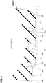
- Fig. 1 shows a meridian cross section of the tire 1 under its normally inflated unloaded condition.
- the normally inflated unloaded condition is such that the tire is mounted on a standard wheel rim and inflated to a standard pressure but loaded with no tire load.
- the standard wheel rim is a wheel rim officially approved or recommended for the tire by standards organizations, i.e. JATMA (Japan and Asia), T&RA (North America), ETRTO (Europe), TRAA (Australia), STRO (Scandinavia), ALAPA (Latin America), ITTAC (India) and the like which are effective in the area where the tire is manufactured, sold or used.
- the standard pressure and a standard tire load are the maximum air pressure and the maximum tire load for the tire specified by the same organization in the Air-pressure/Maximum-load Table or similar list.
- the standard wheel rim is the "standard rim” specified in JATMA, the "Measuring Rim” in ETRTO, the "Design Rim” in TRA or the like.
- the standard pressure is the “maximum air pressure” in JATMA, the “Inflation Pressure” in ETRTO, the maximum pressure given in the “Tire Load Limits at various Cold Inflation Pressures” table in TRA or the like.
- the standard load is the "maximum load capacity" in JATMA, the “Load Capacity” in ETRTO, the maximum value given in the above-mentioned table in TRA or the like.
- an intended tire rotational direction N may be specified in order to effectively bring out performance of tread patterns provided in the tread portion 2 and configurations of the grooved blocks.
- Such intended rotational direction N may be indicated in the sidewall portions 3 of the tire.
- the tire rotational direction N is used and indicated in the figures.
- the terms "heel-side” and “toe-side” are used, wherein the heel-side is intended toward the tire rotational direction N, and the toe-side is intended toward the opposite direction to the tire rotational direction N.
- the tire 1 comprises a tread portion 2 whose radially outer surface defines the tread, a pair of axially spaced bead portions 4 mounted on rim seats and each provided with a bead core 5, a pair of sidewall portions 3 extending between the tread edges and the bead portions, a carcass 6 extending between the bead portions through the tread portion and the sidewall portions, and secured to the bead cores, and a tread reinforcing cord layer 7 disposed radially outside the carcass in the tread portion.
- the tread portion 2 (inclusive of the carcass, tread reinforcing cord layer and a tread rubber thereon) is convexly curved so that the tread face 2a between the tread edges 2t is curved like an arc swelling radially outwardly, and the maximum cross sectional width of the tire 1 occurs between the tread edges 2t, namely, equals to the axial tread width.
- “TWe” denotes a developed tread width between the tread edges 2t along the tread face 2a.
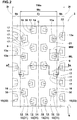
- the tread portion 2 is provided with a plurality of blocks 10 rising from the tread base independently as shown in Figs. 1 and 2 .
- the tread base corresponds to bottoms 9b of tread grooves 9. Due to the low land ratio of the tread portion 2, the term "tread base" is used.
- the land ratio of the tread portion 2 is set in a range of not less than 18%, more preferably not less than 20%, but not more than 35%, more preferably not more than 28%.
- the land ratio (or positive ratio) is a ratio (Lb/L) of the total ground contacting area Lb of the blocks to the overall tread area L. If the land ratio (Lb / L) is less than 18%, the rigidity of the blocks is reduced, and the grip performance on hard ground such as dry asphalt road surface is reduced. If the land ratio of (Lb / L) is more than 35%, there is a possibility that the edge effect is reduced, and the grip performance on soft ground is deteriorated.
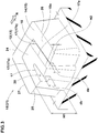
- the blocks 10 each have a ground contacting top surface 10a and a sidewall surface 10b extending radially inwardly from the peripheral edge of the top surface 10a to the tread base (9b).
- the blocks 10 include a grooved block 10 as shown in Fig. 3 , wherein the top surface 10a of the grooved block 10 is provided with a zoning groove 16 dividing the block into a tall section 12 having a higher top surface 13, and a short section 14 having a lower top surface 15 positioned radially inside the higher top surface 13.
- the grooved block 10 has two sections 12 and 14 having different radial heights, the edges 17 of the grooved block are increased which makes it possible to exhibit high edge effect.
- the tall section 12 can be separated from the short section 14 during running, which also enhance the edge effect.
- the difference H2 in the radial height between the higher top surface 13 of the tall section 12 and the lower top surface 15 of the short section 14 is set in a range from 0.3 to 3.0 mm. If the height difference H2 is small, the edge effect from the edge 17a of the tall section 12 may not be effectively improved. If the height difference H2 is large, there is a possibility that the stiffness of the tall section 12 becomes insufficient.
- annular regions of the tread portion 2 are defined as follows: a crown region Cr centered on the tire equator C and having a developed axial width Wc in a range from 25% to 75% of the developed tread width TWe, and a pair of shoulder regions Sh on both sides of the crown region Cr, namely, each extending from the crown region Cr to one of the tread edges.
- the crown region Cr is a region contacting with the ground from straight running conditions to cornering conditions with the moderately leant vehicle body and thus subjected to large loads due to acceleration and deceleration.
- the shoulder region Sh is a region contacting with the ground from cornering conditions with the moderately leant vehicle body to cornering conditions with the largely leant vehicle body, therefore, the opportunity to contact with the ground is less than the crown region Cr.
- each of the blocks 10 is the grooved block 10.
- the blocks 10 include crown blocks 21 (grooved blocks 10) each defined such that the centroid 13a of the higher top surface 13 is disposed in the crown region Cr; and shoulder blocks 22 (grooved blocks 10) each defined such that the centroid 13a of the higher top surface 13 is disposed in the shoulder region Sh.
- the shoulder block 22 in each shoulder region Sh are arranged in the tire circumferential direction along the tread edge.
- the crown blocks 21 are arranged in the tire circumferential direction and the tire axial direction.
- the groove depth (da) of the zoning groove 16 measured from the lower top surface 15 is set to be less than 20% of the maximum radial height H1 of the grooved block 10.
- the rigidity of the grooved block 10 is kept high, thereby the durability of the grooved block 10 is maintained.
- the groove depth (da) of the zoning groove 16 is excessively small, the separation between the tall section 12 and the short section 14 becomes insufficient, and the edge effect is reduced. Therefore, it is preferable that the groove depth (da) of the zoning groove 16 is more than 5% of the maximum height H1 of the grooved block 10.
- the groove width Wa of the zoning groove 16 is preferably set to be not less than 0.5 mm and not more than 3.0 mm.
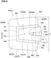
- the crown block 21 has a generally rectangular shape having four sides or edges 23 extending substantially straight.
- the four edges 23 are an axially inner circumferential edge 24 extending in the tire circumferential direction and disposed on the axially inside of the centroid 13a, an axially outer circumferential edge 25 extending in the tire circumferential direction and disposed on the axially outside of the axially inner circumferential edge 24, a heel-side axial edge 26 extending in the tire axial direction and disposed on the heel-side of the centroid 13a and between the axially inner circumferential edge 24 and the axially outer circumferential edge 25, and a toe-side axial edge 27 extending in the tire axial direction and disposed on the toe-side of the centroid 13a of and between the axially inner circumferential edge 24 and the axially outer circumferential edge 25.
- edge extending substantially straight means a linear edge as well as a nonlinear edge 23 (such as the axially outer circumferential edge 25) whose most deviated point 23x from a straight line 23c drawn between both ends 23e of the edge 23 is at a distance La of not more than 30% of the length L1 of the straight line 23c from the straight line 23c.
- the axially inner circumferential edge 24, the heel-side axial edge 26 and the toe-side axial edge 27 are subjected to large forces at the time of acceleration and deceleration during straight running and cornering.
- the axially outer circumferential edge 25 is subjected to smaller forces when compared with the axially inner circumferential edge 24, the heel-side axial edge 26 and the toe-side axial edge 27.
- the above-mentioned zoning groove 16 of the grooved block 10 (crown block 21) is U-shaped, having both ends 16e opened at one of the edges 23 which is, in this embodiment, the axially outer circumferential edge 25. That is, the zoning groove 16 does not reach to the axially inner circumferential edge 24, the heel-side axial edge 26 and the toe-side axial edge 27 which edges are subjected to relatively large forces. Thereby, the rigidity of the block is kept high, and the durability of the block is ensured.
- the zoning groove 16 is composed of a first portion 16A, a second portion 16B and a third portion 16C.
- the first and second portions 16A and 16B extend axially inwardly from the axially outer circumferential edge 25.
- the third portion 16C extends in the tire circumferential direction between the axially inner end 16i of the first portion 16A and the axially inner end 16h of the second portion 16B.
- the second portion 16B is positioned on the toe-side of the first portion 16A.
- each of the first, second and third portions 16A-16C extends straight.
- Such zoning groove 16 can enhance the edge effect of the block edges.
- the higher top surface 13 of the tall section 12 is substantially rectangular.
- the grooved block 10 as the crown block 21 is provided with a second groove 30 disposed in the higher top surface 13 of the tall section 12 in order to increase the block edges 17 to further improve the grip performance.
- the second groove 30 extends straight in the tire axial direction so that an axially inner end 30i is terminated within the higher top surface 13, and an axially outer end 30e is opened at the axially outer circumferential edge 25.
- Such second groove 30 secures its length, while maintaining a high rigidity of the tall section 12, therefore, the durability and the grip performance is improved in good balance.
- an average groove width wb of the second groove 30 is set in a range from 1.0 to 4.0 mm. If the width wb is large, there is a possibility that the rigidity of the tall section 12 becomes insufficient. If the width wb is small, there is a possibility that the second groove 30 is closed when the tall section 12 contacting with the ground, and the edge effect can not be effectively exhibited. From a similar point of view, it is preferable that the groove depth db of the second groove 30 is in a range from 5% to 20% of the maximum height H1 of the grooved block 10.
- the short section 14 is substantially U-shaped in its top view and surrounded by the heel-side axial edge 26, the toe-side axial edge 27, the axially inner circumferential edge 24 and the zoning groove 16.
- the short section 14 comprises an axially inner part 32, a heel-side part 34 and a toe-side part 36.
- the alternate long and two short dashes line shows the boundary between the axially inner part 32 and the heel-side and toe-side parts 34 and 36.
- the axially inner part 32 is the part located on the axially inside of the tall section 12.
- the heel-side part 34 is a part located on the heel-side in the tire rotational direction N of the tall section 12 excluding the axially inner part 32.
- the toe-side part 36 is a part located on the toe-side in the tire rotational direction N of the tall section 12 excluding the axially inner part 32.
- the heel-side axial edge 26 digs into the ground and can exert a significant edge effect
- the heel-side block edge 12a of the tall section 12 digs into the ground and can exert a large edge effect.
- the heel-side block edge 30a formed by the second groove 30 also exerts a large edge effect.
- the heel-side block edge 32a formed by the zoning groove 16 and positioned axially inside the tall section 12 also exerts the edge effect.
- a heel-side block edge portion 36a and the toe-side block edge 36a of the toe-side part 36 behind the tall section 12 have less opportunity to exhibit a high edge effect.
- the toe-side block edge 32b of the axially inner part 32, the toe-side block edge 34b of the heel-side part 34, the toe-side block edge 12b of the tall section 12, and the toe-side block edge formed by the second groove 30 also have less opportunity to exhibit a high edge effect.
- These edges and edge portion are less effective for improving the edge effect of the grooved block (hereinafter the less effective block edges).
- the less effective block edges are indicated by thin line.
- block widths w1 to w3 are acquired from the tall section 12, and block widths w4 to w6 are acquired from the short section 14, and the block width w2 from the tall section 12 is adopted to the smallest value D.
- a tread rubber forming the blocks 10 has a durometer A hardness of from 68 to 85 degrees measured according to JIS-K6253 at a temperature 25 degrees C.
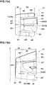
- Fig. 7(a) shows another example of the grooved block 10 (crown block 21) which can be employed alone or in combination with the formed example as another embodiment of the present invention.
- the second groove 30 has both axial ends 30e and 30i closed within the tall section 12 in order to increase the rigidity of the tall section 12 and thereby to improve the durability.
- the effective heel-side edges are indicated by heavy line as in the former example.
- the total length E (mm) of the axial components of the effective heel-side edges is given by the sum of the lengths E1 to E6 wherein E6 is zero as in the former example.
- w2 measured at the outer end 30e of the second groove 30 is adopted as the smallest value D.
- Fig. 7(b) shows still another example of the grooved block 10 (crown block 21) which can be employed alone or in combination with the former examples as another embodiment of the present invention.
- the heel-side axial edge 26 is inclined with respect to the tire axial direction at a larger angle when compared with the former examples.
- the second portion 16B of the zoning groove 16 extends in a zigzag shape. This example is used so that the second portion 16B is positioned on the toe-side in relation to the intended tire rotational direction N, and the heel-side axial edge 26 is actually positioned on the heel-side.
- the effective heel-side edges are indicated by heavy line.
- the total length E (mm) of the axial components of the effective heel-side edges is given by the sum of the lengths E1 to E6 wherein E6 is zero.
- w1 and w2 obtained from the tall section 12 and the widths w3 to w5 obtained from the short section 14 obtained from the tall section 12 is adopted as the smallest value D.
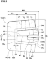
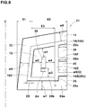
- Fig. 8 shows yet another example of the grooved block 10 (crown block 21) which can be employed alone or in combination with the formed examples as another embodiment of the present invention.
- the zoning groove 16 in this example comprises, in addition to the above-said first portion 16A, second portion 16B and third portion 16C, a fourth portion 16D and a fifth portion 16E.
- the fourth portion 16D is disposed on the axially outside of the third portion 16C and extended in the tire circumferential direction so as to connect between the first portion 16A and the second portion 16B.
- the fifth portion 16E extends in the tire axial direction from the fourth portion 16D to the axially outer circumferential edge 25.
- the second portion 16B in this example is composed of a major first axial portion 29b extending in the tire axial direction from the third portion 16C toward the axially outer circumferential edge 25, a circumferential portion 29a extending in the tire circumferential direction from the first axial portion 29b toward the heel-side axial edge 26, and a second axial portion 29c extending in the tire axial direction from one end of the circumferential portion 29a to the axially outer circumferential edge 25.
- the second groove 30 in this example has both ends terminated within the higher top surface 13, namely, it is an independent groove not connected to any of the grooves.
- the short section 14 comprises an axially outer heel-side part 38 and an axially outer toe-side part 40 on the toe-side thereof in addition to the above-said axially inner part 32, heel-side part 34 and toe-side part 36.
- the axially outer heel-side part 38 is divided by the first portion 16A, the fifth portion 16E and the fourth part 16D and has a rectangular shape in the plan view.
- the axially outer toe-side part 40 is divided by the fifth portion 16E, the second portion 16B and the fourth part 16D and has a rectangular shape in the plan view.
- the length E6 is the sum of E6a, E6b and E6c:
- test vehicle 450 cc motocross bike front tire size: 80/100-21 (rim size 21x1.85), pressure 80 kPa rear tire size: 120/80-19 (rim size 19x2.15), pressure 80 kPa
- test tires were mounted on the test vehicle, and during running on a rough road surface of a test course, the test rider evaluated the grip performance.
Landscapes
- Engineering & Computer Science (AREA)
- Mechanical Engineering (AREA)
- Tires In General (AREA)
Applications Claiming Priority (1)
| Application Number | Priority Date | Filing Date | Title |
|---|---|---|---|
| JP2016249686A JP6834464B2 (ja) | 2016-12-22 | 2016-12-22 | タイヤ |
Publications (2)
| Publication Number | Publication Date |
|---|---|
| EP3339057A1 true EP3339057A1 (fr) | 2018-06-27 |
| EP3339057B1 EP3339057B1 (fr) | 2019-05-01 |
Family
ID=60629561
Family Applications (1)
| Application Number | Title | Priority Date | Filing Date |
|---|---|---|---|
| EP17206110.3A Active EP3339057B1 (fr) | 2016-12-22 | 2017-12-08 | Pneumatique de moto pour terrain accidente |
Country Status (3)
| Country | Link |
|---|---|
| US (1) | US10857837B2 (fr) |
| EP (1) | EP3339057B1 (fr) |
| JP (1) | JP6834464B2 (fr) |
Cited By (1)
| Publication number | Priority date | Publication date | Assignee | Title |
|---|---|---|---|---|
| EP3677442A1 (fr) * | 2018-12-28 | 2020-07-08 | Sumitomo Rubber Industries, Ltd. | Pneu hors route |
Families Citing this family (3)
| Publication number | Priority date | Publication date | Assignee | Title |
|---|---|---|---|---|
| JP7110784B2 (ja) * | 2018-07-19 | 2022-08-02 | 住友ゴム工業株式会社 | タイヤ |
| JP7290056B2 (ja) * | 2019-04-10 | 2023-06-13 | 住友ゴム工業株式会社 | タイヤ |
| JP2024019954A (ja) * | 2022-08-01 | 2024-02-14 | 住友ゴム工業株式会社 | 不整地走行用の二輪車用タイヤ |
Citations (4)
| Publication number | Priority date | Publication date | Assignee | Title |
|---|---|---|---|---|
| EP2657048A1 (fr) * | 2012-04-27 | 2013-10-30 | Sumitomo Rubber Industries, Ltd. | Bandage pneumatique pour roulage sur terrain brusque |
| EP2682283A1 (fr) * | 2012-07-06 | 2014-01-08 | Sumitomo Rubber Industries, Ltd. | Pneu pour terrains accidentés |
| JP2014141163A (ja) * | 2013-01-23 | 2014-08-07 | Sumitomo Rubber Ind Ltd | 不整地走行用の自動二輪車用タイヤ |
| EP2990233A1 (fr) * | 2013-04-24 | 2016-03-02 | Bridgestone Corporation | Pneu |
Family Cites Families (7)
| Publication number | Priority date | Publication date | Assignee | Title |
|---|---|---|---|---|
| JP5154972B2 (ja) * | 2008-02-19 | 2013-02-27 | 株式会社ブリヂストン | 二輪車用空気入りタイヤ |
| JP5303255B2 (ja) * | 2008-12-18 | 2013-10-02 | 株式会社ブリヂストン | 二輪車用タイヤ |
| JP5161933B2 (ja) * | 2010-07-28 | 2013-03-13 | 住友ゴム工業株式会社 | 不整地走行用の自動二輪車用タイヤ |
| JP2013030615A (ja) * | 2011-07-28 | 2013-02-07 | Sanyo Electric Co Ltd | 太陽電池 |
| JP5629293B2 (ja) * | 2012-08-09 | 2014-11-19 | 住友ゴム工業株式会社 | 不整地走行用の空気入りタイヤ |
| JP5802223B2 (ja) | 2013-01-30 | 2015-10-28 | 住友ゴム工業株式会社 | 不整地走行用の自動二輪車用タイヤ |
| JP6093637B2 (ja) * | 2013-04-24 | 2017-03-08 | 株式会社ブリヂストン | タイヤ |
-
2016
- 2016-12-22 JP JP2016249686A patent/JP6834464B2/ja active Active
-
2017
- 2017-12-08 EP EP17206110.3A patent/EP3339057B1/fr active Active
- 2017-12-20 US US15/848,132 patent/US10857837B2/en active Active
Patent Citations (4)
| Publication number | Priority date | Publication date | Assignee | Title |
|---|---|---|---|---|
| EP2657048A1 (fr) * | 2012-04-27 | 2013-10-30 | Sumitomo Rubber Industries, Ltd. | Bandage pneumatique pour roulage sur terrain brusque |
| EP2682283A1 (fr) * | 2012-07-06 | 2014-01-08 | Sumitomo Rubber Industries, Ltd. | Pneu pour terrains accidentés |
| JP2014141163A (ja) * | 2013-01-23 | 2014-08-07 | Sumitomo Rubber Ind Ltd | 不整地走行用の自動二輪車用タイヤ |
| EP2990233A1 (fr) * | 2013-04-24 | 2016-03-02 | Bridgestone Corporation | Pneu |
Cited By (2)
| Publication number | Priority date | Publication date | Assignee | Title |
|---|---|---|---|---|
| EP3677442A1 (fr) * | 2018-12-28 | 2020-07-08 | Sumitomo Rubber Industries, Ltd. | Pneu hors route |
| US11518195B2 (en) | 2018-12-28 | 2022-12-06 | Sumitomo Rubber Industries, Ltd. | Off-road tyre |
Also Published As
| Publication number | Publication date |
|---|---|
| US20180178588A1 (en) | 2018-06-28 |
| US10857837B2 (en) | 2020-12-08 |
| JP2018103673A (ja) | 2018-07-05 |
| JP6834464B2 (ja) | 2021-02-24 |
| EP3339057B1 (fr) | 2019-05-01 |
Similar Documents
| Publication | Publication Date | Title |
|---|---|---|
| EP3056359B1 (fr) | Pneumatique | |
| EP2412547B1 (fr) | Pneu de motocyclette pour terrains accidentés | |
| EP2412546B1 (fr) | Pneu de motocyclette pour terrains accidentés | |
| EP2660078B1 (fr) | Pneu | |
| EP2423006B1 (fr) | Pneu de motocyclette pour terrains accidentés | |
| US10800212B2 (en) | Pneumatic tire | |
| EP1977910A1 (fr) | Pneu hors route pour motocyclette | |
| EP2390114B1 (fr) | Pneu de motocyclette pour terrains accidentés | |
| US9457623B2 (en) | Pneumatic tire for running on rough terrain | |
| EP2631087A1 (fr) | Pneu | |
| US9623709B2 (en) | Pneumatic tire for running on rough terrain | |
| EP3299183B1 (fr) | Pneumatique | |
| EP2263888A1 (fr) | Pneu pour conduire sur terrain accidenté | |
| EP2682283B1 (fr) | Pneu pour terrains accidentés | |
| EP3339057B1 (fr) | Pneumatique de moto pour terrain accidente | |
| EP3318420B1 (fr) | Pneu pour terrain accidenté | |
| US10987975B2 (en) | Motorcycle tire | |
| US20210061018A1 (en) | Tire | |
| EP3611037A1 (fr) | Pneu pour terrain accidenté | |
| EP2821257B1 (fr) | Pneu |
Legal Events
| Date | Code | Title | Description |
|---|---|---|---|
| PUAI | Public reference made under article 153(3) epc to a published international application that has entered the european phase |
Free format text: ORIGINAL CODE: 0009012 |
|
| STAA | Information on the status of an ep patent application or granted ep patent |
Free format text: STATUS: THE APPLICATION HAS BEEN PUBLISHED |
|
| AK | Designated contracting states |
Kind code of ref document: A1 Designated state(s): AL AT BE BG CH CY CZ DE DK EE ES FI FR GB GR HR HU IE IS IT LI LT LU LV MC MK MT NL NO PL PT RO RS SE SI SK SM TR |
|
| AX | Request for extension of the european patent |
Extension state: BA ME |
|
| STAA | Information on the status of an ep patent application or granted ep patent |
Free format text: STATUS: REQUEST FOR EXAMINATION WAS MADE |
|
| 17P | Request for examination filed |
Effective date: 20181024 |
|
| RBV | Designated contracting states (corrected) |
Designated state(s): AL AT BE BG CH CY CZ DE DK EE ES FI FR GB GR HR HU IE IS IT LI LT LU LV MC MK MT NL NO PL PT RO RS SE SI SK SM TR |
|
| GRAP | Despatch of communication of intention to grant a patent |
Free format text: ORIGINAL CODE: EPIDOSNIGR1 |
|
| STAA | Information on the status of an ep patent application or granted ep patent |
Free format text: STATUS: GRANT OF PATENT IS INTENDED |
|
| RIC1 | Information provided on ipc code assigned before grant |
Ipc: B60C 11/03 20060101AFI20181128BHEP Ipc: B60C 11/11 20060101ALI20181128BHEP Ipc: B60C 11/13 20060101ALI20181128BHEP |
|
| INTG | Intention to grant announced |
Effective date: 20181214 |
|
| GRAS | Grant fee paid |
Free format text: ORIGINAL CODE: EPIDOSNIGR3 |
|
| GRAA | (expected) grant |
Free format text: ORIGINAL CODE: 0009210 |
|
| STAA | Information on the status of an ep patent application or granted ep patent |
Free format text: STATUS: THE PATENT HAS BEEN GRANTED |
|
| AK | Designated contracting states |
Kind code of ref document: B1 Designated state(s): AL AT BE BG CH CY CZ DE DK EE ES FI FR GB GR HR HU IE IS IT LI LT LU LV MC MK MT NL NO PL PT RO RS SE SI SK SM TR |
|
| REG | Reference to a national code |
Ref country code: GB Ref legal event code: FG4D |
|
| REG | Reference to a national code |
Ref country code: CH Ref legal event code: EP Ref country code: AT Ref legal event code: REF Ref document number: 1126423 Country of ref document: AT Kind code of ref document: T Effective date: 20190515 |
|
| REG | Reference to a national code |
Ref country code: DE Ref legal event code: R096 Ref document number: 602017003670 Country of ref document: DE |
|
| REG | Reference to a national code |
Ref country code: IE Ref legal event code: FG4D |
|
| REG | Reference to a national code |
Ref country code: NL Ref legal event code: MP Effective date: 20190501 |
|
| REG | Reference to a national code |
Ref country code: LT Ref legal event code: MG4D |
|
| PG25 | Lapsed in a contracting state [announced via postgrant information from national office to epo] |
Ref country code: ES Free format text: LAPSE BECAUSE OF FAILURE TO SUBMIT A TRANSLATION OF THE DESCRIPTION OR TO PAY THE FEE WITHIN THE PRESCRIBED TIME-LIMIT Effective date: 20190501 Ref country code: PT Free format text: LAPSE BECAUSE OF FAILURE TO SUBMIT A TRANSLATION OF THE DESCRIPTION OR TO PAY THE FEE WITHIN THE PRESCRIBED TIME-LIMIT Effective date: 20190901 Ref country code: AL Free format text: LAPSE BECAUSE OF FAILURE TO SUBMIT A TRANSLATION OF THE DESCRIPTION OR TO PAY THE FEE WITHIN THE PRESCRIBED TIME-LIMIT Effective date: 20190501 Ref country code: LT Free format text: LAPSE BECAUSE OF FAILURE TO SUBMIT A TRANSLATION OF THE DESCRIPTION OR TO PAY THE FEE WITHIN THE PRESCRIBED TIME-LIMIT Effective date: 20190501 Ref country code: NO Free format text: LAPSE BECAUSE OF FAILURE TO SUBMIT A TRANSLATION OF THE DESCRIPTION OR TO PAY THE FEE WITHIN THE PRESCRIBED TIME-LIMIT Effective date: 20190801 Ref country code: FI Free format text: LAPSE BECAUSE OF FAILURE TO SUBMIT A TRANSLATION OF THE DESCRIPTION OR TO PAY THE FEE WITHIN THE PRESCRIBED TIME-LIMIT Effective date: 20190501 Ref country code: NL Free format text: LAPSE BECAUSE OF FAILURE TO SUBMIT A TRANSLATION OF THE DESCRIPTION OR TO PAY THE FEE WITHIN THE PRESCRIBED TIME-LIMIT Effective date: 20190501 Ref country code: SE Free format text: LAPSE BECAUSE OF FAILURE TO SUBMIT A TRANSLATION OF THE DESCRIPTION OR TO PAY THE FEE WITHIN THE PRESCRIBED TIME-LIMIT Effective date: 20190501 Ref country code: HR Free format text: LAPSE BECAUSE OF FAILURE TO SUBMIT A TRANSLATION OF THE DESCRIPTION OR TO PAY THE FEE WITHIN THE PRESCRIBED TIME-LIMIT Effective date: 20190501 |
|
| PG25 | Lapsed in a contracting state [announced via postgrant information from national office to epo] |
Ref country code: LV Free format text: LAPSE BECAUSE OF FAILURE TO SUBMIT A TRANSLATION OF THE DESCRIPTION OR TO PAY THE FEE WITHIN THE PRESCRIBED TIME-LIMIT Effective date: 20190501 Ref country code: RS Free format text: LAPSE BECAUSE OF FAILURE TO SUBMIT A TRANSLATION OF THE DESCRIPTION OR TO PAY THE FEE WITHIN THE PRESCRIBED TIME-LIMIT Effective date: 20190501 Ref country code: GR Free format text: LAPSE BECAUSE OF FAILURE TO SUBMIT A TRANSLATION OF THE DESCRIPTION OR TO PAY THE FEE WITHIN THE PRESCRIBED TIME-LIMIT Effective date: 20190802 Ref country code: BG Free format text: LAPSE BECAUSE OF FAILURE TO SUBMIT A TRANSLATION OF THE DESCRIPTION OR TO PAY THE FEE WITHIN THE PRESCRIBED TIME-LIMIT Effective date: 20190801 |
|
| REG | Reference to a national code |
Ref country code: AT Ref legal event code: MK05 Ref document number: 1126423 Country of ref document: AT Kind code of ref document: T Effective date: 20190501 |
|
| PG25 | Lapsed in a contracting state [announced via postgrant information from national office to epo] |
Ref country code: IS Free format text: LAPSE BECAUSE OF FAILURE TO SUBMIT A TRANSLATION OF THE DESCRIPTION OR TO PAY THE FEE WITHIN THE PRESCRIBED TIME-LIMIT Effective date: 20190901 |
|
| PG25 | Lapsed in a contracting state [announced via postgrant information from national office to epo] |
Ref country code: CZ Free format text: LAPSE BECAUSE OF FAILURE TO SUBMIT A TRANSLATION OF THE DESCRIPTION OR TO PAY THE FEE WITHIN THE PRESCRIBED TIME-LIMIT Effective date: 20190501 Ref country code: AT Free format text: LAPSE BECAUSE OF FAILURE TO SUBMIT A TRANSLATION OF THE DESCRIPTION OR TO PAY THE FEE WITHIN THE PRESCRIBED TIME-LIMIT Effective date: 20190501 Ref country code: RO Free format text: LAPSE BECAUSE OF FAILURE TO SUBMIT A TRANSLATION OF THE DESCRIPTION OR TO PAY THE FEE WITHIN THE PRESCRIBED TIME-LIMIT Effective date: 20190501 Ref country code: EE Free format text: LAPSE BECAUSE OF FAILURE TO SUBMIT A TRANSLATION OF THE DESCRIPTION OR TO PAY THE FEE WITHIN THE PRESCRIBED TIME-LIMIT Effective date: 20190501 Ref country code: DK Free format text: LAPSE BECAUSE OF FAILURE TO SUBMIT A TRANSLATION OF THE DESCRIPTION OR TO PAY THE FEE WITHIN THE PRESCRIBED TIME-LIMIT Effective date: 20190501 Ref country code: SK Free format text: LAPSE BECAUSE OF FAILURE TO SUBMIT A TRANSLATION OF THE DESCRIPTION OR TO PAY THE FEE WITHIN THE PRESCRIBED TIME-LIMIT Effective date: 20190501 |
|
| REG | Reference to a national code |
Ref country code: DE Ref legal event code: R097 Ref document number: 602017003670 Country of ref document: DE |
|
| PG25 | Lapsed in a contracting state [announced via postgrant information from national office to epo] |
Ref country code: IT Free format text: LAPSE BECAUSE OF FAILURE TO SUBMIT A TRANSLATION OF THE DESCRIPTION OR TO PAY THE FEE WITHIN THE PRESCRIBED TIME-LIMIT Effective date: 20190501 Ref country code: SM Free format text: LAPSE BECAUSE OF FAILURE TO SUBMIT A TRANSLATION OF THE DESCRIPTION OR TO PAY THE FEE WITHIN THE PRESCRIBED TIME-LIMIT Effective date: 20190501 |
|
| PLBE | No opposition filed within time limit |
Free format text: ORIGINAL CODE: 0009261 |
|
| STAA | Information on the status of an ep patent application or granted ep patent |
Free format text: STATUS: NO OPPOSITION FILED WITHIN TIME LIMIT |
|
| PG25 | Lapsed in a contracting state [announced via postgrant information from national office to epo] |
Ref country code: TR Free format text: LAPSE BECAUSE OF FAILURE TO SUBMIT A TRANSLATION OF THE DESCRIPTION OR TO PAY THE FEE WITHIN THE PRESCRIBED TIME-LIMIT Effective date: 20190501 |
|
| 26N | No opposition filed |
Effective date: 20200204 |
|
| PG25 | Lapsed in a contracting state [announced via postgrant information from national office to epo] |
Ref country code: PL Free format text: LAPSE BECAUSE OF FAILURE TO SUBMIT A TRANSLATION OF THE DESCRIPTION OR TO PAY THE FEE WITHIN THE PRESCRIBED TIME-LIMIT Effective date: 20190501 |
|
| PG25 | Lapsed in a contracting state [announced via postgrant information from national office to epo] |
Ref country code: SI Free format text: LAPSE BECAUSE OF FAILURE TO SUBMIT A TRANSLATION OF THE DESCRIPTION OR TO PAY THE FEE WITHIN THE PRESCRIBED TIME-LIMIT Effective date: 20190501 |
|
| REG | Reference to a national code |
Ref country code: BE Ref legal event code: MM Effective date: 20191231 |
|
| PG25 | Lapsed in a contracting state [announced via postgrant information from national office to epo] |
Ref country code: MC Free format text: LAPSE BECAUSE OF FAILURE TO SUBMIT A TRANSLATION OF THE DESCRIPTION OR TO PAY THE FEE WITHIN THE PRESCRIBED TIME-LIMIT Effective date: 20190501 |
|
| PG25 | Lapsed in a contracting state [announced via postgrant information from national office to epo] |
Ref country code: IE Free format text: LAPSE BECAUSE OF NON-PAYMENT OF DUE FEES Effective date: 20191208 Ref country code: LU Free format text: LAPSE BECAUSE OF NON-PAYMENT OF DUE FEES Effective date: 20191208 |
|
| PG25 | Lapsed in a contracting state [announced via postgrant information from national office to epo] |
Ref country code: BE Free format text: LAPSE BECAUSE OF NON-PAYMENT OF DUE FEES Effective date: 20191231 |
|
| PG25 | Lapsed in a contracting state [announced via postgrant information from national office to epo] |
Ref country code: CY Free format text: LAPSE BECAUSE OF FAILURE TO SUBMIT A TRANSLATION OF THE DESCRIPTION OR TO PAY THE FEE WITHIN THE PRESCRIBED TIME-LIMIT Effective date: 20190501 |
|
| PG25 | Lapsed in a contracting state [announced via postgrant information from national office to epo] |
Ref country code: MT Free format text: LAPSE BECAUSE OF FAILURE TO SUBMIT A TRANSLATION OF THE DESCRIPTION OR TO PAY THE FEE WITHIN THE PRESCRIBED TIME-LIMIT Effective date: 20190501 Ref country code: HU Free format text: LAPSE BECAUSE OF FAILURE TO SUBMIT A TRANSLATION OF THE DESCRIPTION OR TO PAY THE FEE WITHIN THE PRESCRIBED TIME-LIMIT; INVALID AB INITIO Effective date: 20171208 |
|
| REG | Reference to a national code |
Ref country code: CH Ref legal event code: PL |
|
| PG25 | Lapsed in a contracting state [announced via postgrant information from national office to epo] |
Ref country code: CH Free format text: LAPSE BECAUSE OF NON-PAYMENT OF DUE FEES Effective date: 20201231 Ref country code: LI Free format text: LAPSE BECAUSE OF NON-PAYMENT OF DUE FEES Effective date: 20201231 |
|
| PG25 | Lapsed in a contracting state [announced via postgrant information from national office to epo] |
Ref country code: MK Free format text: LAPSE BECAUSE OF FAILURE TO SUBMIT A TRANSLATION OF THE DESCRIPTION OR TO PAY THE FEE WITHIN THE PRESCRIBED TIME-LIMIT Effective date: 20190501 |
|
| GBPC | Gb: european patent ceased through non-payment of renewal fee |
Effective date: 20211208 |
|
| PG25 | Lapsed in a contracting state [announced via postgrant information from national office to epo] |
Ref country code: GB Free format text: LAPSE BECAUSE OF NON-PAYMENT OF DUE FEES Effective date: 20211208 |
|
| P01 | Opt-out of the competence of the unified patent court (upc) registered |
Effective date: 20230510 |
|
| PGFP | Annual fee paid to national office [announced via postgrant information from national office to epo] |
Ref country code: FR Payment date: 20231108 Year of fee payment: 7 Ref country code: DE Payment date: 20231031 Year of fee payment: 7 |