EP3338014B1 - Ölkreislaufsystem einer brennkraftmaschine mit einem druck- und temperaturgesteuerten ventil - Google Patents
Ölkreislaufsystem einer brennkraftmaschine mit einem druck- und temperaturgesteuerten ventil Download PDFInfo
- Publication number
- EP3338014B1 EP3338014B1 EP16754470.9A EP16754470A EP3338014B1 EP 3338014 B1 EP3338014 B1 EP 3338014B1 EP 16754470 A EP16754470 A EP 16754470A EP 3338014 B1 EP3338014 B1 EP 3338014B1
- Authority
- EP
- European Patent Office
- Prior art keywords
- valve
- pressure
- temperature
- oil circuit
- circuit system
- Prior art date
- Legal status (The legal status is an assumption and is not a legal conclusion. Google has not performed a legal analysis and makes no representation as to the accuracy of the status listed.)
- Active
Links
- 238000002485 combustion reaction Methods 0.000 title claims description 11
- 230000001419 dependent effect Effects 0.000 claims description 7
- 229910001285 shape-memory alloy Inorganic materials 0.000 claims description 6
- 230000000295 complement effect Effects 0.000 claims description 3
- 238000001816 cooling Methods 0.000 description 2
- 238000007789 sealing Methods 0.000 description 2
- 239000000110 cooling liquid Substances 0.000 description 1
- 238000007599 discharging Methods 0.000 description 1
- 230000001747 exhibiting effect Effects 0.000 description 1
- 230000006870 function Effects 0.000 description 1
- 239000000314 lubricant Substances 0.000 description 1
- 230000001050 lubricating effect Effects 0.000 description 1
- 239000007921 spray Substances 0.000 description 1
- 238000011144 upstream manufacturing Methods 0.000 description 1
Images
Classifications
-
- F—MECHANICAL ENGINEERING; LIGHTING; HEATING; WEAPONS; BLASTING
- F16—ENGINEERING ELEMENTS AND UNITS; GENERAL MEASURES FOR PRODUCING AND MAINTAINING EFFECTIVE FUNCTIONING OF MACHINES OR INSTALLATIONS; THERMAL INSULATION IN GENERAL
- F16K—VALVES; TAPS; COCKS; ACTUATING-FLOATS; DEVICES FOR VENTING OR AERATING
- F16K31/00—Actuating devices; Operating means; Releasing devices
- F16K31/002—Actuating devices; Operating means; Releasing devices actuated by temperature variation
-
- F—MECHANICAL ENGINEERING; LIGHTING; HEATING; WEAPONS; BLASTING
- F01—MACHINES OR ENGINES IN GENERAL; ENGINE PLANTS IN GENERAL; STEAM ENGINES
- F01M—LUBRICATING OF MACHINES OR ENGINES IN GENERAL; LUBRICATING INTERNAL COMBUSTION ENGINES; CRANKCASE VENTILATING
- F01M5/00—Heating, cooling, or controlling temperature of lubricant; Lubrication means facilitating engine starting
- F01M5/005—Controlling temperature of lubricant
- F01M5/007—Thermostatic control
-
- F—MECHANICAL ENGINEERING; LIGHTING; HEATING; WEAPONS; BLASTING
- F16—ENGINEERING ELEMENTS AND UNITS; GENERAL MEASURES FOR PRODUCING AND MAINTAINING EFFECTIVE FUNCTIONING OF MACHINES OR INSTALLATIONS; THERMAL INSULATION IN GENERAL
- F16K—VALVES; TAPS; COCKS; ACTUATING-FLOATS; DEVICES FOR VENTING OR AERATING
- F16K1/00—Lift valves or globe valves, i.e. cut-off apparatus with closure members having at least a component of their opening and closing motion perpendicular to the closing faces
- F16K1/12—Lift valves or globe valves, i.e. cut-off apparatus with closure members having at least a component of their opening and closing motion perpendicular to the closing faces with streamlined valve member around which the fluid flows when the valve is opened
- F16K1/126—Lift valves or globe valves, i.e. cut-off apparatus with closure members having at least a component of their opening and closing motion perpendicular to the closing faces with streamlined valve member around which the fluid flows when the valve is opened actuated by fluid
-
- F—MECHANICAL ENGINEERING; LIGHTING; HEATING; WEAPONS; BLASTING
- F16—ENGINEERING ELEMENTS AND UNITS; GENERAL MEASURES FOR PRODUCING AND MAINTAINING EFFECTIVE FUNCTIONING OF MACHINES OR INSTALLATIONS; THERMAL INSULATION IN GENERAL
- F16K—VALVES; TAPS; COCKS; ACTUATING-FLOATS; DEVICES FOR VENTING OR AERATING
- F16K31/00—Actuating devices; Operating means; Releasing devices
- F16K31/12—Actuating devices; Operating means; Releasing devices actuated by fluid
- F16K31/122—Actuating devices; Operating means; Releasing devices actuated by fluid the fluid acting on a piston
- F16K31/1221—Actuating devices; Operating means; Releasing devices actuated by fluid the fluid acting on a piston one side of the piston being spring-loaded
-
- F—MECHANICAL ENGINEERING; LIGHTING; HEATING; WEAPONS; BLASTING
- F16—ENGINEERING ELEMENTS AND UNITS; GENERAL MEASURES FOR PRODUCING AND MAINTAINING EFFECTIVE FUNCTIONING OF MACHINES OR INSTALLATIONS; THERMAL INSULATION IN GENERAL
- F16K—VALVES; TAPS; COCKS; ACTUATING-FLOATS; DEVICES FOR VENTING OR AERATING
- F16K31/00—Actuating devices; Operating means; Releasing devices
- F16K31/12—Actuating devices; Operating means; Releasing devices actuated by fluid
- F16K31/122—Actuating devices; Operating means; Releasing devices actuated by fluid the fluid acting on a piston
- F16K31/124—Actuating devices; Operating means; Releasing devices actuated by fluid the fluid acting on a piston servo actuated
-
- F—MECHANICAL ENGINEERING; LIGHTING; HEATING; WEAPONS; BLASTING
- F16—ENGINEERING ELEMENTS AND UNITS; GENERAL MEASURES FOR PRODUCING AND MAINTAINING EFFECTIVE FUNCTIONING OF MACHINES OR INSTALLATIONS; THERMAL INSULATION IN GENERAL
- F16N—LUBRICATING
- F16N2270/00—Controlling
- F16N2270/50—Condition
- F16N2270/56—Temperature
Definitions
- the present invention relates to an oil circulation system of an internal combustion engine with a pressure and temperature-controlled valve.
- thermostatic valve To control an oil cooler in an oil circuit of an internal combustion engine, a so-called thermostatic valve is used as a rule.
- Classic thermostatic valves are connected via expansion elements, such as Wachsdehnstoffimplantation.
- a temperature control valve is known, which is controlled by means of such a temperature expansion element.
- a temperature-controlled oil spray nozzle for piston cooling with a control valve which has a control opening associated control member which is biased via a first actuator in a closing the control port end position and biased by a second actuator opposite and can be brought into an open position.
- the force acting on the control member by a lubricant via the control opening Drucckraft acts perpendicular to the direction of movement of the control member. This is to a particularly simple structure can be achieved.
- the DE 10 2009 023 824 A discloses an oil circulation system of an internal combustion engine with a pressure and temperature controlled valve according to the preamble of claim 1.
- the EP 2 816 206 A1 discloses a nozzle for discharging a cooling liquid toward a piston of an internal combustion engine of a vehicle.
- the present invention therefore addresses the problem of providing an improved embodiment for a pressure- and temperature-controlled valve, which is characterized both by low switching times and by low costs.
- the present invention is based on the general idea, to control a pressure and temperature controlled valve in an oil circuit of an internal combustion engine, a bimetallic element or a shape memory alloy exhibiting switching element to use, but this does not directly switch a valve element, but only an inflow into a cylinder over which a valve element designed as a pressure-controlled piston can be moved. Due to the fact that in the solution according to the invention only one inlet opening to the pressure chamber of the respective bimetallic element or switching element must be opened or closed, this can be made comparatively small and thus cost, since the actual adjustment of the valve element by the pressure in Cylinder takes place.
- the pressure and temperature-controlled valve according to the invention which can be arranged in an oil circuit of an internal combustion engine, in this case has a pressure-controlled piston, which translationally in the cylinder described above is adjustable and is lifted in a first position of a valve seat, thereby allowing a flow through the valve, while the piston is pressed in a second position with a valve head on the valve seat and thereby closes the valve.
- the piston divides the cylinder into a pressure chamber and a counterpressure space, wherein a return spring is arranged in the counterpressure space.
- the pressure chamber now has the inlet opening described above, which can be closed and opened in a temperature-dependent manner by a bimetallic element or a switching element having a shape memory alloy.
- the oil temperature is less than 80 ° C, so is the bimetallic element or the switching element in its inlet opening occluding initial position, whereby the pressure chamber is not acted upon by a corresponding oil pressure, which leads to an adjustment of the piston in its second position. Rather, in this state, the return spring arranged in the counter-pressure chamber causes the piston to be returned to its first position, thereby lifting the valve head from the valve seat and opening the valve.
- the valve does not have to be completely closed, but can also be partially closed at lower pressure of the oil.
- a pressure and temperature-controlled valve can be arranged, for example, at a branch downstream of the oil pump and upstream of an oil cooler, wherein a partial oil flow is passed to a filter device when the valve is open.
- valve closes at least partially, so that at least part or all of the oil flow is now conducted via the oil cooler and cooled there.
- Pressure and temperature-controlled valve it is thus possible on the one hand to design an extremely fast, ie almost abruptly, switchable valve, which on the other hand can be formed inexpensively due to a bimetallic element or switching element required only small actuating forces.
- a switching temperature (limit temperature) of the bimetallic element or the switching element is about 80 ° C. At about 80 ° C it is necessary to maintain the lubricating power of the oil to prevent further increase in temperature as far as possible, so that in this case an increased cooling of the oil should take place.
- the valve according to the invention closes at about 80 ° C, whereupon the entire oil flow is passed through the oil cooler.
- the piston has a frusto-conical valve head, while the valve seat has a conical surface, which is designed to be complementary to the valve head.
- the piston and the pressure chamber are arranged centrally in the valve and are annularly flowed around by the oil flowing through the valve.
- the bimetallic element or the switching element on a circular disk-like shape.
- a circular disk-like shape has said bimetal element or the switching element, of course, only in an initial state in which it is pressed in this form by the oil pressure against the inlet opening of the pressure chamber and thereby closes the inlet opening. Due to the restoring force of the return spring disposed in the counter-pressure space, the piston remains in its valve-opening position due to the closed inlet opening, as a result of which the oil delivered by an oil pump remains Flow through the valve and can be guided to a filter device.
- the circular disk-like bimetallic element or the sound element deforms to a spherical segment-like shape and thereby opens the inlet opening.
- the bimetallic element or the switching element may also be formed rectangular or strip-shaped.
- the present invention is further based on the general idea of equipping an oil circulation system of an internal combustion engine with such a previously described pressure and temperature-controlled valve.
- an oil flow can be deflected comparatively quickly, namely when the switching temperature is reached, so that when the switching temperature is reached or exceeded, it is guided not only via a filter device but mainly or exclusively via the oil cooler.
- the valve is connected on the output side to the filter device and on the input side to an output of an oil pump.
- the counterpressure space of the valve is connected to a crankcase, so that the same pressure p prevails in the counterpressure space, as in the crankcase.
- the valve opening force is thus effected in the back pressure chamber not only by the return spring arranged there, but also by the pressure in the crankcase.
- the pressure in the back pressure chamber is smaller when the valve is closed and the same when opening the valve as in the pressure chamber.
- a defined leakage at the cylinder sealing seat, that is between the cylinder and the piston is required.
- the pressure is reduced when the inlet opening is closed, so that the return spring can move the piston and open the valve.
- the switching temperature can be between 60 and 130 ° C.
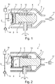
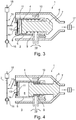
- Fig. 1 to 4 has a pressure and temperature-controlled valve 1, which is arranged in an oil circuit 2 of an internal combustion engine 3, a pressure-controlled piston 4, which is mounted translationally adjustable in a cylinder 5.
- the piston 4 is between a first position (see Fig. 1 and 3 ) and a second position (see Fig. 2 and 4 ) adjustable, wherein connected to the piston 4 valve head 6 is lifted in the first position of an associated valve seat 7 and thereby the valve 1 is opened (see. Fig. 1 and 3 ), while the piston 4 a second position with the valve head 6 rests on the valve seat 7 and thereby the valve 1 closes (see. Fig. 2 and 4 ).
- the piston 4 divides the cylinder 5 in a pressure chamber 8 and a counter-pressure chamber 9, wherein in the latter a return spring 10 is arranged.
- a volume of the pressure chamber 8 and the counter-pressure chamber 9 is dependent on the position of the piston 4.
- the pressure chamber 8 now has an inlet opening 11 which is temperature-dependent on a bimetallic element 12 (cf. Fig. 1 and 2 ) or one, a shape memory alloy having switching element 13 (see 3 and 4 ) is lockable and openable.
- the present inventive valve 1 offers the great advantage, due to the bimetallic element 12 and the switching element 13 can cause an opening or closing of the valve 1 comparatively quickly, in particular even abruptly, while still being able to be formed relatively inexpensive, since the Bimetal element 12 and the switching element 13 is used only to open or close the inlet opening 11 and thereby has to apply almost no restoring forces and therefore can be made small.
- the switching element 13 falls below a predefined temperature, in particular a switching temperature, in one of the inlet opening 11 closing position (see. Fig. 3 ).
- the switching temperature of the bimetallic element 12 and the switching element 13 may be, for example, 80 ° C.
- valve seat 7 has a conical surface which is complementary to the valve head 6 is formed.
- the bimetallic element 12 and the switching element 13 in turn preferably has a circular disk-like shape, but may alternatively be formed strip or rectangular.
- the valve 1 according to the invention is embedded in an oil circulation system 15 of the internal combustion engine 3, wherein the valve 1 and in particular the pressure chamber 8 are connected on the input side, depending of course on the switching state of the bimetallic element 12 and the switching element 13, to an output of an oil pump 16. On the output side, the valve 1 is connected to a filter device 17.
- valve 1 If one considers the valve 1 according to the invention as a function of its switching positions, it can be seen that when the piston 4 is in its first position, the valve 1 is open (cf. Fig. 1 and 3 ), so that a conveyed by the oil pump 16 oil flow between an oil cooler 18 and the filter device 17 is divided. Such a division of the oil pump 16 promoted oil flow is carried out up to the aforementioned limit temperature or switching temperature of the bimetallic element 12 and the switching element 13. If the switching temperature is reached or exceeded, the bimetallic element 12 and the switching element 13 opens the inlet opening 11th , whereupon the pressure chamber 8 is acted upon by the oil pressure generated by the oil pump 16, whereby the piston 4 in its second position (see. Fig.
- the counter-pressure chamber 9 is connected to a crankcase 19, so that prevails in the counter-pressure chamber 9, the same pressure p, as in the crankcase 19.
- An opening movement of the valve 1 is thus by both the return spring 10 and by the in Crankcase 19 prevailing pressure p supported.
- a closing movement of the valve 1 or its piston 4 is thus effected by the oil pressure generated by the oil pump 16 against the actuating force of the return spring 10 and counter to the pressure prevailing in the crankcase 19 pressure p.
- the pressure in the back pressure chamber 9 is smaller when valve closing and valve opening the same size as in the pressure chamber 8.
- a pressure equalization between the pressure chamber 8 and the back pressure chamber 9 also a defined leakage at the cylinder sealing seat, that is between the cylinder 5 and the Piston 4, needed.
- the pressure is reduced at a closed inlet opening 11, so that the return spring 10 can move the piston 4 and the valve 1 can open. Accordingly, an opening of the valve 1 can only take place if a force resulting from pressure in the counterpressure space 9 and return spring 10 is greater than the force resulting from the pressure in the pressure space 8.
- Due to the possibility of leakage at the cylinder seat a pressure equalization between the pressure chamber 8 and the counter-pressure chamber 9 can be achieved and the piston 4 due to the restoring force of the return spring 10 are adjusted in its open position.
- the switching temperature can be between 60 and 130 ° C, preferably at about 80 ° C, lie.
Landscapes
- Engineering & Computer Science (AREA)
- General Engineering & Computer Science (AREA)
- Mechanical Engineering (AREA)
- Physics & Mathematics (AREA)
- Fluid Mechanics (AREA)
- Temperature-Responsive Valves (AREA)
- Lubrication Of Internal Combustion Engines (AREA)
Description
- Die vorliegende Erfindung betrifft ein Ölkreislaufsystem einer Brennkraftmaschine mit einem druck- und temperaturgesteuerten Ventil.
- Zur Ansteuerung eines Ölkühlers in einem Ölkreislauf einer Brennkraftmaschine wird in der Regel ein sogenanntes Thermostatventil verwendet. Klassische Thermostatventile werden dabei über Dehnstoffelemente, wie beispielsweise Wachsdehnstoffelemente, geschaltet.
- Aus der
DE 20 26 629 U ist ein Temperaturregelventil bekannt, welches mittels eines solchen Temperaturdehnelements gesteuert wird. - Aus der
DE 102 61 180 A1 ist eine temperaturgeregelte Ölspritzdüse zur Kolbenkühlung mit einem Regelventil bekannt, welches ein einer Steueröffnung zugeordnetes Steuerglied aufweist, das über ein erstes Stellteil in eine die Steueröffnung verschließenden Endlage vorgespannt ist und über ein zweites Stellteil entgegengesetzt vorgespannt und in eine geöffnete Stellung bringbar ist. Die durch ein Schmiermittel über die Steueröffnung auf das Steuerglied wirkende Drucckraft, wirkt dabei senkrecht zur Bewegungsrichtung des Steuerglieds. Hierdurch soll ein besonders einfacher Aufbau erreicht werden können. - Nachteilig bei den aus dem Stand der Technik bekannten Ventilen ist jedoch, dass diese durch die Verwendung von bekannten Dehnstoffelementen vergleichsweise lange Schaltzeiten aufweisen und dadurch zum schnellen Schalten ungeeignet sind. Aus dem Stand der Technik sind anstelle der bekannten Dehnstoffelemente selbstverständlich auch sogenannte Formgedächtnislegierungen bekannt, die zwar einerseits ein vergleichsweise schnelles Schalten ermöglichen, andererseits jedoch aufgrund von lediglich geringen aufbringbaren Stellkräften dementsprechend groß ausgebildet werden müssen und dadurch vergleichsweise teuer sind, wodurch wiederum ein Nachteil entsteht.
- Die
DE 10 2009 023 824 A offenbart ein Ölkreislaufsystem einer Brennkraftmaschine mit einem druck- und temperaturgesteuerten Ventil gemäß dem Oberbegriff von Anspruch 1. - Die
EP 2 816 206 A1 offenbart eine Düse zum Ausstoßen einer Kühlflüssigkeit in Richtung eines Kolbens eines Verbrennungsmotors eines Fahrzeugs. - Die vorliegende Erfindung beschäftigt sich daher mit dem Problem, für ein druck- und temperaturgesteuertes Ventil eine verbesserte Ausführungsform anzugeben, welche sich sowohl durch geringe Schaltzeiten als auch durch geringe Kosten auszeichnet.
- Dieses Problem wird erfindungsgemäß durch den Gegenstand des unabhängigen Anspruchs gelöst. Vorteilhafte Ausführungsformen sind Gegenstand der abhängigen Ansprüche.
- Die vorliegende Erfindung beruht auf dem allgemeinen Gedanken, zur Steuerung eines druck- und temperaturgesteuerten Ventils in einem Ölkreislauf einer Brennkraftmaschine ein Bimetallelement oder ein, eine Formgedächtnislegierung aufweisendes Schaltelement, einzusetzen, hierüber jedoch nicht direkt ein Ventilelement zu schalten, sondern lediglich einen Zufluss in einen Zylinder, über welchen ein als druckgesteuerter Kolben ausgebildetes Ventilelement bewegt werden kann. Durch den Umstand, dass bei der erfindungsgemäßen Lösung lediglich eine Zulauföffnung zum Druckraum von dem jeweiligen Bimetallelement bzw. Schaltelement geöffnet bzw. zu geschlossen werden muss, kann dieses vergleichsweise klein und damit auch kostengünstig ausgebildet werden, da die eigentliche Verstellung des Ventilelements durch den Druck im Zylinder erfolgt. Das erfindungsgemäße druck- und temperaturgesteuerte Ventil, welches in einem Ölkreislauf einer Brennkraftmaschine angeordnet sein kann, weist dabei einen druckgesteuerten Kolben auf, der in dem zuvor beschriebenen Zylinder translatorisch verstellbar ist und in einer ersten Stellung von einem Ventilsitz abgehoben ist und dadurch einen Durchfluss durch das Ventil ermöglicht, während der Kolben in einer zweiten Stellung mit einem Ventilkopf auf den Ventilsitz gedrückt ist und dadurch das Ventil verschließt. Der Kolben unterteilt dabei den Zylinder in einen Druckraum und einen Gegendruckraum, wobei in dem Gegendruckraum eine Rückstellfeder angeordnet ist. Erfindungsgemäß weist nun der Druckraum die zuvor beschriebene Zulauföffnung auf, die temperaturabhängig von einem Bimetallelement oder einem, eine Formgedächtnislegierung aufweisenden Schaltelement verschließbar und zu öffnen ist. Beträgt somit beispielsweise die Öltemperatur weniger als 80 °C, so befindet sich das Bimetallelement bzw. das Schaltelement in seiner die Zulauföffnung verschließenden Ausgangslage, wodurch der Druckraum nicht mit einem entsprechenden Öldruck beaufschlagt wird, der zu einem Verstellen des Kolbens in seine zweite Stellung führt. Vielmehr bewirkt in diesem Zustand die im Gegendruckraum angeordnete Rückstellfeder, dass der Kolben in seine erste Stellung zurückgefahren wird und dadurch der Ventilkopf vom Ventilsitz abhebt und das Ventil öffnet. Steigt die Temperatur auf bzw. über eine für das Bimetallelement bzw. das Schaltelement kritische Grenztemperatur, beispielsweise 80 °C, springt dieses schlagartig um und öffnet die Zulauföffnung zum Druckraum, woraufhin der Druckraum mit von einer Ölpumpe gefördertem Öl beaufschlagt wird, was zu einem Verstellen des Kolbens in seine zweite Stellung und damit zu einem Schließen des Ventils führt. Selbstverständlich muss dabei das Ventil nicht komplett verschlossen werden, sondern kann bei geringerem Druck des Öls auch nur teilweise geschlossen werden. Ein derartiges druck- und temperaturgesteuertes Ventil kann beispielsweise an einer Abzweigung stromab der Ölpumpe und stromauf eines Ölkühlers angeordnet werden, wobei bei geöffnetem Ventil ein Teilölstrom zu einer Filtereinrichtung geleitet wird. Steigt die Temperatur des Öls über die zuvor definierte Grenztemperatur, schließt das Ventil zumindest teilweise, so dass zumindest ein Teil des oder der gesamte Ölstrom nun über den Ölkühler geleitet und dort gekühlt wird. Mit dem erfindungsgemäßen druck- und temperaturgesteuerten Ventil ist es somit möglich, einerseits ein extrem schnell, d.h. nahezu schlagartig, schaltbares Ventil zu konzipieren, welches andererseits aufgrund eines lediglich kleine Stellkräfte erforderlichen Bimetallelements bzw. Schaltelements kostengünstig ausgebildet werden kann.
- Bei einer vorteilhaften Weiterbildung der erfindungsgemäßen Lösung beträgt eine Schalttemperatur (Grenztemperatur) des Bimetallelements oder des Schaltelements ca. 80°C. Bei ca. 80 °C ist es zur Erhaltung der Schmierkraft des Öls erforderlich, einen weiteren Temperaturanstieg nach Möglichkeit zu verhindern, so dass in diesem Fall eine verstärkte Kühlung des Öls erfolgen sollte. Zu diesem Zweck schließt das erfindungsgemäße Ventil bei ca. 80 °C, woraufhin der gesamte Ölstrom über den Ölkühler geleitet wird.
- Bei einer weiteren vorteilhaften Ausführungsform der erfindungsgemäßen Lösung weist der Kolben einen kegelstumpfförmigen Ventilkopf auf, während der Ventilsitz eine Konusfläche aufweist, die komplementär zum Ventilkopf ausgebildet ist. Hierdurch kann ein besonders strömungsgünstiges Ventil geschaffen werden, wobei der Kolben und der Druckraum zentral in dem Ventil angeordnet sind und ringförmig vom das Ventil durchströmenden Öl umströmt werden.
- Zweckmäßig weisen das Bimetallelement oder das Schaltelement eine kreisscheibenartige Form auf. Eine derartige kreisscheibenartige Form besitzt das besagte Bimetallelement bzw. das Schaltelement selbstverständlich lediglich in einem Ausgangszustand, in welchem es in dieser Gestalt vom Öldruck gegen die Zulauföffnung des Druckraums gepresst wird und dadurch die Zulauföffnung verschließt. Durch die geschlossene Zulauföffnung verbleibt der Kolben aufgrund der Rückstellkraft der im Gegendruckraum angeordneten Rückstellfeder in seiner das Ventil öffnenden Stellung, wodurch das seitens einer Ölpumpe geförderte Öl das Ventil durchströmen und zu einer Filtereinrichtung geführt werden kann. Ist die Grenztemperatur bzw. Schalttemperatur erreicht, so verformt sich das kreisscheibenartige Bimetallelement oder das Schallelement zu einer kugelsegmentartigen Gestalt und öffnet dadurch die Zulauföffnung. In gleicher Weise kann selbstverständlich das Bimetallelement bzw. das Schaltelement auch rechteckig oder streifenförmig ausgebildet sein.
- Die vorliegende Erfindung beruht weiter auf dem allgemeinen Gedanken, ein Ölkreislaufsystem einer Brennkraftmaschine mit einem solchen, zuvor beschriebenen druck- und temperaturgesteuerten Ventil auszustatten. Hierdurch kann ein Ölstrom vergleichsweise schnell, nämlich beim Erreichen der Schalttemperatur, umgelenkt werden, so dass er beim Erreichen oder Überschreiten der Schalttemperatur nicht nur über eine Filtereinrichtung, sondern hauptsächlich oder ausschließlich über den Ölkühler geleitet wird. Das Ventil ist hierzu ausgangsseitig mit der Filtereinrichtung und eingangsseitig mit einem Ausgang einer Ölpumpe verbunden.
- Erfindungsgemäß ist der Gegendruckraum des Ventils mit einem Kurbelgehäuse verbunden, so dass im Gegendruckraum derselbe Druck p herrscht, wie im Kurbelgehäuse. Die das Ventil öffnende Kraft wird somit im Gegendruckraum nicht nur von der dort angeordneten Rückstellfeder bewirkt, sondern zusätzlich auch vom Druck im Kurbelgehäuse. Der Druck im Gegendruckraum ist beim Ventilschließen kleiner und beim Ventilöffnen gleich groß wie im Druckraum. Um einen Druckausgleich zwischen dem Druckraum und dem Gegendruckraum erreichen zu können, wird auch eine definierte Leckage am Zylinderdichtsitz, das heißt zwischen dem Zylinder und dem Kolben benötigt. Hier erfolgt der Druckabbau bei verschlossener Zulauföffnung, so dass die Rückstellfeder den Kolben bewegen und das Ventil öffnen kann. Die Schalttemperatur kann zwischen 60 und 130°C liegen.
- Weitere wichtige Merkmale und Vorteile der Erfindung ergeben sich aus den Unteransprüchen, aus den Zeichnungen und aus der zugehörigen Figurenbeschreibung anhand der Zeichnungen.
- Bevorzugte Ausführungsbeispiele der Erfindung sind in den Zeichnungen dargestellt und werden in der nachfolgenden Beschreibung näher erläutert, wobei sich gleiche Bezugszeichen auf gleiche oder ähnliche oder funktional gleiche Komponenten beziehen.
- Dabei zeigen, jeweils schematisch,
- Fig. 1
- ein erfindungsgemäßes druck- und temperaturgesteuertes Ventil mit einem Bimetall in einer ersten Stellung,
- Fig. 2
- eine Darstellung wie in
Fig. 1 , jedoch in einer zweiten Stellung, - Fig. 3
- eine Darstellung wie in
Fig. 1 , jedoch mit einem, eine Formgedächtnislegierung aufweisenden Schaltelement, - Fig. 4
- eine Darstellung wie in
Fig. 3 , jedoch in einer zweiten Stellung. - Entsprechend den
Fig. 1 bis 4 , weist ein druck- und temperaturgesteuertes Ventil 1, welches in einem Ölkreislauf 2 einer Brennkraftmaschine 3 angeordnet ist, einen druckgesteuerten Kolben 4 auf, der in einem Zylinder 5 translatorisch verstellbar gelagert ist. Der Kolben 4 ist dabei zwischen einer ersten Stellung (vgl. dieFig. 1 und3 ) und einer zweiten Stellung (vgl. dieFig. 2 und4 ) verstellbar, wobei ein mit dem Kolben 4 verbundener Ventilkopf 6 in der ersten Stellung von einem zugehörigen Ventilsitz 7 abgehoben und dadurch das Ventil 1 geöffnet ist (vgl.Fig. 1 und3 ), während der Kolben 4 einer zweiten Stellung mit dem Ventilkopf 6 auf dem Ventilsitz 7 aufliegt und dadurch das Ventil 1 verschließt (vgl.Fig. 2 und4 ). Der Kolben 4 unterteilt dabei den Zylinder 5 in einen Druckraum 8 und einen Gegendruckraum 9, wobei in letzterem eine Rückstellfeder 10 angeordnet ist. Ein Volumen des Druckraums 8 bzw. des Gegendruckraums 9 ist dabei abhängig von der Stellung des Kolbens 4. Erfindungsgemäß weist nun der Druckraum 8 eine Zulauföffnung 11 auf, die temperaturabhängig von einem Bimetallelement 12 (vgl. dieFig. 1 und 2 ) oder einem, eine Formgedächtnislegierung aufweisenden Schaltelement 13 (vgl. dieFig. 3 und 4 ) verschließbar und öffenbar ist. - Das vorliegende erfindungsgemäße Ventil 1 bietet dabei den großen Vorteil, aufgrund des Bimetallelements 12 bzw. des Schaltelements 13 ein Öffnen bzw. Schließen des Ventils 1 vergleichsweise schnell, insbesondere sogar schlagartig bewirken zu können, und dabei trotzdem vergleichsweise kostengünstig ausgebildet werden zu können, da das Bimetallelement 12 bzw. das Schaltelement 13 lediglich zum Öffnen bzw. Schließen der Zulauföffnung 11 verwendet wird und dadurch nahezu keine Stellkräfte aufbringen muss und deshalb klein ausgebildet werden kann.
- Betrachtet man das erfindungsgemäße Ventil 1 gemäß den
Fig. 3 und 4 , so kann man erkennen, dass zur Rückstellung des Schaltelements 13 eine Federeinrichtung 14 vorgesehen ist, die das Schaltelement 13 bei Unterschreiten einer vordefinierten Temperatur, insbesondere einer Schalttemperatur, in eine die Zulauföffnung 11 schließende Lage (vgl.Fig. 3 ) vorspannt. Die Schalttemperatur des Bimetallelements 12 bzw. des Schaltelements 13 kann dabei beispielsweise 80 °C betragen. - Betrachtet man den Kolben 4 näher, so kann man erkennen, dass dieser den besagten kegelstumpfförmigen Ventilkopf 6 aufweist, wobei der Ventilsitz 7 eine Konusfläche besitzt, die komplementär zum Ventilkopf 6 ausgebildet ist. Das Bimetallelement 12 bzw. das Schaltelement 13 wiederum besitzt vorzugsweise eine kreisscheibenartige Gestalt, kann aber alternativ auch streifen- oder rechteckförmig ausgebildet sein.
- Eingebettet ist das erfindungsgemäße Ventil 1 in ein Ölkreislaufsystem 15 der Brennkraftmaschine 3, wobei das Ventil 1 und insbesondere dessen Druckraum 8 eingangsseitig, abhängig natürlich vom Schaltzustand des Bimetallelements 12 bzw. des Schaltelements 13, mit einem Ausgang einer Ölpumpe 16 verbunden sind. Ausgangsseitig ist das Ventil 1 mit einer Filtereinrichtung 17 verbunden.
- Betrachtet man das erfindungsgemäße Ventil 1 in Abhängigkeit seiner Schaltstellungen, so kann man erkennen, dass bei einem sich in seiner ersten Stellung befindlichen Kolben 4 das Ventil 1 geöffnet ist (vgl. die
Fig. 1 und3 ), so dass ein von der Ölpumpe 16 geförderter Ölstrom zwischen einem Ölkühler 18 und der Filtereinrichtung 17 aufgeteilt wird. Eine derartige Aufteilung von der Ölpumpe 16 geförderten Ölstroms erfolgt dabei bis zu der zuvor genannten Grenztemperatur bzw. Schalttemperatur des Bimetallelements 12 bzw. des Schaltelements 13. Wird die Schalttemperatur erreicht bzw. überschritten, so öffnet das Bimetallelement 12 bzw. das Schaltelement 13 die Zulauföffnung 11, woraufhin der Druckraum 8 mit dem von der Ölpumpe 16 erzeugten Öldruck beaufschlagt wird, wodurch sich der Kolben 4 in seine zweite Stellung (vgl.Fig. 2 und4 ) oder öldruckabhängig zumindest in Richtung der zweiten Stellung verstellt und dadurch das Ventil 1 zumindest teilweise schließt. In der zweiten Stellung strömt nun der seitens der Ölpumpe 16 geförderte Ölstrom nicht mehr über die Filtereinrichtung 17, sondern ausschließlich über den Ölkühler 18, bis die Temperatur des Öls wieder unter die Grenztemperatur bzw. unter die Schalttemperatur des Bimetallelements 12 bzw. des Schaltelements 13 fällt und dadurch das Ventil 1 wieder öffnet. - Selbstverständlich kann durch ein lediglich teilweises Schließen des Ventils 1 auch nur ein größerer Teilölstrom über den Ölkühler 18 geschickt werden.
- Betrachtet man die
Fig. 1 bis 4 weiter, so kann man erkennen, dass der Gegendruckraum 9 mit einem Kurbelgehäuse 19 verbunden ist, so dass im Gegendruckraum 9 derselbe Druck p herrscht, wie im Kurbelgehäuse 19. Eine Öffnungsbewegung des Ventils 1 wird somit sowohl durch die Rückstellfeder 10 als auch durch den im Kurbelgehäuse 19 herrschenden Druck p unterstützt. Eine Schließbewegung des Ventils 1 bzw. dessen Kolben 4 erfolgt somit durch den seitens der Ölpumpe 16 erzeugten Öldruck entgegen der Stellkraft der Rückstellfeder 10 sowie entgegen des im Kurbelgehäuse 19 herrschenden Drucks p. Der Druck im Gegendruckraum 9 ist beim Ventilschließen kleiner und beim Ventilöffnen gleich groß wie im Druckraum 8. Um einen Druckausgleich zwischen dem Druckraum 8 und dem Gegendruckraum 9 erreichen zu können, wird auch eine definierte Leckage am Zylinderdichtsitz, das heißt zwischen dem Zylinder 5 und dem Kolben 4, benötigt. Hier erfolgt der Druckabbau bei verschlossener Zulauföffnung 11, so dass die Rückstellfeder 10 den Kolben 4 bewegen und das Ventil 1 öffnen kann. Ein Öffnen des Ventils 1 kann demnach nur dann erfolgen, sofern eine aus Druck im Gegendruckraum 9 und Rückstellfeder 10 resultierende Kraft größer ist als die aus dem Druck im Druckraum 8 resultierende Kraft. Durch die Leckagemöglichkeit am Zylindersitz kann ein Druckausgleich zwischen Druckraum 8 und Gegendruckraum 9 erreicht und der Kolben 4 aufgrund der Rückstellkraft der Rückstellfeder 10 in seine Öffnungsstellung verstellt werden. Die Schalttemperatur kann zwischen 60 und 130 °C, vorzugsweise bei ca. 80 °C, liegen. - Mit dem erfindungsgemäßen Ölkreislaufsystem ist es somit möglich, die Vorteile eines schnellen, insbesondere sogar schlagartig, schaltenden Ventils 1 mit den Vorteilen eines kostengünstigen Ventils 1 zu kombinieren, wodurch erhebliche Vorteile im Vergleich zu bisher aus dem Stand der Technik bekannten Ventilen, welche mittels beispielsweise Wachsdehnstoffelementen geschaltet wurden, erzielt werden können. Der Erfindungsgedanke liegt hierbei insbesondere darin, das zum Schalten des Ventils 1 erforderliche Bimetallelement 12 bzw. Schaltelement 13 nicht direkt zum Verstellen des Kolbens 4 zu verwenden, wozu vergleichsweise hohe Stellkräfte und damit auch ein großes und teures Bimetallelement 12 bzw. Schaltelement 13 erforderlich wäre, sondern lediglich zum Öffnen bzw. Schließen der Zulauföffnung 11 des Druckraums 8, wodurch das Bimetallelement 12 bzw. das Schaltelement 13 vergleichsweise klein und damit kostengünstig ausgebildet werden kann.
Claims (7)
- Ölkreislaufsystem (15) einer Brennkraftmaschine (3) mit einem druck- und temperaturgesteuerten Ventil (1), das Ventil (1) aufweisend- einen druckgesteuerten Kolben (4), der in einem Zylinder (5) translatorisch verstellbar gelagert ist und in einer ersten Stellung von einem Ventilsitz (7) abgehoben ist und dadurch einen Durchfluss durch das Ventil (1) ermöglicht, während der Kolben (4) in einer zweiten Stellung mit einem Ventilkopf (6) auf den Ventilsitz (7) gedrückt ist und das Ventil (1) verschließt,
dadurch gekennzeichnet,- dass der Kolben (4) den Zylinder (5) in einen Druckraum (8) und einen Gegendruckraum (9) unterteilt,- dass in dem Gegendruckraum (9) eine Rückstellfeder (10) angeordnet ist,- dass der Druckraum (8) eine Zulauföffnung (11) aufweist, die temperaturabhängig von einem Bimetallelement (12) oder einem, eine Formgedächtnislegierung aufweisenden Schaltelement (13) verschließbar und öffenbar ist,- dass der Gegendruckraum (9) des Ventils (1) mit einem Kurbelgehäuse (19) verbunden ist, sodass im Gegendruckraum (9) derselbe Druck p herrscht, wie im Kurbelgehäuse (19). - Ölkreislaufsystem nach Anspruch 1 mit einem druck- und temperaturgesteuerten Ventil entsprechend der zweiten Alternative,
dadurch gekennzeichnet,
dass eine Federeinrichtung (14) vorgesehen ist, die das Schaltelement (13) bei Unterschreiten einer vordefinierten Temperatur in eine die Zulauföffnung (11) schließende Lage vorspannt. - Ölkreislaufsystem nach Anspruch 1 oder 2,
dadurch gekennzeichnet,
dass eine Schalttemperatur des Bimetallelements (12) oder des Schaltelements (13) zwischen 60 °C und 130 °C, vorzugsweise bei ca. 80 °C liegt. - Ölkreislaufsystem nach einem der vorhergehenden Ansprüche,
dadurch gekennzeichnet,- dass der Kolben (4) einen kegelstumpfförmigen Ventilkopf (6) aufweist,- dass der Ventilsitz (7) eine Konusfläche aufweist, die komplementär zum Ventilkopf (6) ausgebildet ist. - Ölkreislaufsystem nach einem der vorhergehenden Ansprüche,
dadurch gekennzeichnet,
dass das Bimetallelement (12) oder das Schaltelement (13) eine kreisscheibenartige Form aufweisen. - Ölkreislaufsystem nach einem der vorhergehenden Ansprüche,
dadurch gekennzeichnet,
dass das Ventil (1) und insbesondere der Druckraum (8) eingangsseitig mit einem Ausgang einer Ölpumpe (16) verbunden sind. - Ölkreislaufsystem nach einem der vorhergehenden Ansprüche,
dadurch gekennzeichnet,
dass das Ventil (1) ausgangsseitig mit einer Filtereinrichtung (17) verbunden ist.
Applications Claiming Priority (2)
| Application Number | Priority Date | Filing Date | Title |
|---|---|---|---|
| DE102015215774.1A DE102015215774A1 (de) | 2015-08-19 | 2015-08-19 | Druck- und temperaturgesteuertes Ventil in einem Ölkreislauf einer Brennkraftmaschine |
| PCT/EP2016/069262 WO2017029227A1 (de) | 2015-08-19 | 2016-08-12 | Druck- und temperaturgesteuertes ventil in einem ölkreislauf einer brennkraftmaschine |
Publications (2)
| Publication Number | Publication Date |
|---|---|
| EP3338014A1 EP3338014A1 (de) | 2018-06-27 |
| EP3338014B1 true EP3338014B1 (de) | 2019-10-09 |
Family
ID=56787455
Family Applications (1)
| Application Number | Title | Priority Date | Filing Date |
|---|---|---|---|
| EP16754470.9A Active EP3338014B1 (de) | 2015-08-19 | 2016-08-12 | Ölkreislaufsystem einer brennkraftmaschine mit einem druck- und temperaturgesteuerten ventil |
Country Status (3)
| Country | Link |
|---|---|
| EP (1) | EP3338014B1 (de) |
| DE (1) | DE102015215774A1 (de) |
| WO (1) | WO2017029227A1 (de) |
Families Citing this family (12)
| Publication number | Priority date | Publication date | Assignee | Title |
|---|---|---|---|---|
| DE102017200874A1 (de) * | 2016-11-14 | 2018-05-17 | Mahle International Gmbh | Elektrische Kühlmittelpumpe |
| CN107061850A (zh) * | 2017-03-10 | 2017-08-18 | 上海航天设备制造总厂 | 一种根据环境温度变化控制管路通断的装置 |
| FR3067437B1 (fr) * | 2017-06-13 | 2019-08-02 | Bontaz Centre R & D | Gicleur de fluide axial a clapet evente |
| CN109780260B (zh) * | 2017-11-13 | 2020-06-09 | 浙江三花汽车零部件有限公司 | 调温阀 |
| CN109780261B (zh) * | 2017-11-13 | 2020-05-22 | 浙江三花汽车零部件有限公司 | 调温阀 |
| CN109780310B (zh) * | 2017-11-13 | 2020-05-22 | 浙江三花汽车零部件有限公司 | 调温阀 |
| CN110469698B (zh) * | 2019-08-22 | 2020-07-10 | 华中科技大学 | 一种紧凑型压力自补偿全海深截止阀 |
| CN110566465B (zh) * | 2019-10-08 | 2025-05-02 | 珠海凌达压缩机有限公司 | 一种控制冷冻油油量的容器结构及其压缩机 |
| DE102021205656A1 (de) | 2021-06-02 | 2022-12-08 | Magna powertrain gmbh & co kg | Kühlsystem für eine lastpunktabhängige Kühlung eines Rotors einer elektrischen Maschine |
| DE102022207221B4 (de) * | 2022-07-14 | 2024-11-28 | Joma-Polytec Gmbh | Elektrische Maschine mit einem passiven Ventil |
| DE102022212415B4 (de) * | 2022-11-21 | 2025-05-28 | Magna powertrain gmbh & co kg | Kühlsystem zur Kühlung einer elektrischen Maschine |
| CN117267451A (zh) * | 2023-10-31 | 2023-12-22 | 西安热工研究院有限公司 | 一种可调温度的机械式高温关断阀 |
Citations (1)
| Publication number | Priority date | Publication date | Assignee | Title |
|---|---|---|---|---|
| EP2816206A1 (de) * | 2013-06-20 | 2014-12-24 | Renault S.A.S. | Düse zum Spritzen einer Kühlflüssigkeit an ein Ventil |
Family Cites Families (7)
| Publication number | Priority date | Publication date | Assignee | Title |
|---|---|---|---|---|
| DE2026629B2 (de) | 1970-05-30 | 1977-06-02 | Temperatur-Regelventil Vereinigte Flugtechnische Werke-Fokker GmbH, 2800 Bremen | Temperatur-regelventil |
| DE3912118A1 (de) * | 1989-04-13 | 1990-10-18 | Inter Control Koehler Hermann | Ventileinrichtung zur temperaturabhaengigen steuerung eines medienstromes |
| US6840257B2 (en) * | 2001-05-08 | 2005-01-11 | Alberto Arena | Proportional valve with shape memory alloy actuator |
| DE10261180A1 (de) | 2002-12-20 | 2004-07-01 | Daimlerchrysler Ag | Temperaturgeregelte Ölspritzdüse zur Kolbenkühlung |
| CN101358659B (zh) * | 2007-07-30 | 2010-10-06 | 徐佳义 | 蒸具自动节流排气阀门装置 |
| TWI422787B (zh) * | 2008-11-20 | 2014-01-11 | Globe Union Ind Corp | Can be cold water recovery of the water device |
| DE102009023824A1 (de) * | 2009-06-04 | 2010-12-16 | Audi Ag | Thermostat-Druckbegrenzungsventil, selbstregelnde Fluidpumpe und Schmierölkreislauf einer Brennkraftmaschine |
-
2015
- 2015-08-19 DE DE102015215774.1A patent/DE102015215774A1/de not_active Withdrawn
-
2016
- 2016-08-12 EP EP16754470.9A patent/EP3338014B1/de active Active
- 2016-08-12 WO PCT/EP2016/069262 patent/WO2017029227A1/de not_active Ceased
Patent Citations (1)
| Publication number | Priority date | Publication date | Assignee | Title |
|---|---|---|---|---|
| EP2816206A1 (de) * | 2013-06-20 | 2014-12-24 | Renault S.A.S. | Düse zum Spritzen einer Kühlflüssigkeit an ein Ventil |
Also Published As
| Publication number | Publication date |
|---|---|
| WO2017029227A1 (de) | 2017-02-23 |
| EP3338014A1 (de) | 2018-06-27 |
| DE102015215774A1 (de) | 2017-02-23 |
Similar Documents
| Publication | Publication Date | Title |
|---|---|---|
| EP3338014A1 (de) | Druck- und temperaturgesteuertes ventil in einem ölkreislauf einer brennkraftmaschine | |
| EP3387225B1 (de) | Fluidversorgungssystem | |
| EP2848787B1 (de) | Steuerventil für eine Schmiermitteldüse | |
| EP2960561B1 (de) | Hydraulikventil | |
| EP3161299B1 (de) | Gasventil | |
| DE102005018904B3 (de) | Thermostatventil für das Kühlsystem einer Verbrennungskraftmaschine | |
| EP2423498A1 (de) | Passives Mengenbegrenzungsventil | |
| DE102007006872A1 (de) | Kugelsitzventil mit konturiertem Steuerstößel | |
| EP3452705B1 (de) | Fluidversorgungssystem | |
| DE102016107773A1 (de) | Hydraulikventil | |
| EP3446006A1 (de) | VENTIL ZUM VERSCHLIEßEN UND ÖFFNEN EINES LEITUNGSSYSTEMS | |
| DE202015009000U1 (de) | Fluidversorgungssystem einer Brennkraftmaschine | |
| EP1291520A2 (de) | Druckregelanordnung | |
| DE102011087511A1 (de) | Druckregelventil | |
| EP3217052B1 (de) | Hydraulikventil | |
| DE102015222745A1 (de) | Ventil mit Stromregel- und Druckbegrenzungsfunktion | |
| DE10131202A1 (de) | Ventileinrichtung zur temperaturabhängigen Umschaltung der Überstömmenge einer Diesel-Einspritzpumpe | |
| DE102014212103B4 (de) | Ventilanordnung | |
| EP0879374B1 (de) | Wegeventil | |
| EP1420148B1 (de) | Flüssigkeitsmodul zur erzeugung konstanter Flüssigkeitsdrücke | |
| DE102004004095B3 (de) | Druckbegrenzungsvorrichtung | |
| EP3309644A1 (de) | Ventilvorrichtung sowie druckregelsystem mit einer solchen ventilvorrichtung | |
| WO2014202473A1 (de) | Druckregelventil | |
| DE102018201734A1 (de) | Überströmventil für ein Kraftstoffeinspritzsystem, Kraftstoffeinspritzsystem | |
| WO2018001677A1 (de) | VENTIL ZUM VERSCHLIEßEN UND ÖFFNEN EINES LEITUNGSSYSTEMS |
Legal Events
| Date | Code | Title | Description |
|---|---|---|---|
| STAA | Information on the status of an ep patent application or granted ep patent |
Free format text: STATUS: THE INTERNATIONAL PUBLICATION HAS BEEN MADE |
|
| PUAI | Public reference made under article 153(3) epc to a published international application that has entered the european phase |
Free format text: ORIGINAL CODE: 0009012 |
|
| STAA | Information on the status of an ep patent application or granted ep patent |
Free format text: STATUS: REQUEST FOR EXAMINATION WAS MADE |
|
| 17P | Request for examination filed |
Effective date: 20171201 |
|
| AK | Designated contracting states |
Kind code of ref document: A1 Designated state(s): AL AT BE BG CH CY CZ DE DK EE ES FI FR GB GR HR HU IE IS IT LI LT LU LV MC MK MT NL NO PL PT RO RS SE SI SK SM TR |
|
| AX | Request for extension of the european patent |
Extension state: BA ME |
|
| DAV | Request for validation of the european patent (deleted) | ||
| DAX | Request for extension of the european patent (deleted) | ||
| GRAP | Despatch of communication of intention to grant a patent |
Free format text: ORIGINAL CODE: EPIDOSNIGR1 |
|
| STAA | Information on the status of an ep patent application or granted ep patent |
Free format text: STATUS: GRANT OF PATENT IS INTENDED |
|
| RIC1 | Information provided on ipc code assigned before grant |
Ipc: F16K 31/00 20060101ALI20190426BHEP Ipc: F16K 31/124 20060101ALI20190426BHEP Ipc: F01M 1/16 20060101ALI20190426BHEP Ipc: F16K 31/122 20060101AFI20190426BHEP Ipc: F16K 1/12 20060101ALI20190426BHEP |
|
| INTG | Intention to grant announced |
Effective date: 20190517 |
|
| GRAS | Grant fee paid |
Free format text: ORIGINAL CODE: EPIDOSNIGR3 |
|
| GRAA | (expected) grant |
Free format text: ORIGINAL CODE: 0009210 |
|
| STAA | Information on the status of an ep patent application or granted ep patent |
Free format text: STATUS: THE PATENT HAS BEEN GRANTED |
|
| AK | Designated contracting states |
Kind code of ref document: B1 Designated state(s): AL AT BE BG CH CY CZ DE DK EE ES FI FR GB GR HR HU IE IS IT LI LT LU LV MC MK MT NL NO PL PT RO RS SE SI SK SM TR |
|
| REG | Reference to a national code |
Ref country code: GB Ref legal event code: FG4D Free format text: NOT ENGLISH |
|
| REG | Reference to a national code |
Ref country code: CH Ref legal event code: EP |
|
| REG | Reference to a national code |
Ref country code: IE Ref legal event code: FG4D Free format text: LANGUAGE OF EP DOCUMENT: GERMAN |
|
| REG | Reference to a national code |
Ref country code: DE Ref legal event code: R096 Ref document number: 502016007036 Country of ref document: DE |
|
| REG | Reference to a national code |
Ref country code: AT Ref legal event code: REF Ref document number: 1189225 Country of ref document: AT Kind code of ref document: T Effective date: 20191115 |
|
| REG | Reference to a national code |
Ref country code: NL Ref legal event code: MP Effective date: 20191009 |
|
| REG | Reference to a national code |
Ref country code: LT Ref legal event code: MG4D |
|
| PG25 | Lapsed in a contracting state [announced via postgrant information from national office to epo] |
Ref country code: NO Free format text: LAPSE BECAUSE OF FAILURE TO SUBMIT A TRANSLATION OF THE DESCRIPTION OR TO PAY THE FEE WITHIN THE PRESCRIBED TIME-LIMIT Effective date: 20200109 Ref country code: LT Free format text: LAPSE BECAUSE OF FAILURE TO SUBMIT A TRANSLATION OF THE DESCRIPTION OR TO PAY THE FEE WITHIN THE PRESCRIBED TIME-LIMIT Effective date: 20191009 Ref country code: PL Free format text: LAPSE BECAUSE OF FAILURE TO SUBMIT A TRANSLATION OF THE DESCRIPTION OR TO PAY THE FEE WITHIN THE PRESCRIBED TIME-LIMIT Effective date: 20191009 Ref country code: ES Free format text: LAPSE BECAUSE OF FAILURE TO SUBMIT A TRANSLATION OF THE DESCRIPTION OR TO PAY THE FEE WITHIN THE PRESCRIBED TIME-LIMIT Effective date: 20191009 Ref country code: PT Free format text: LAPSE BECAUSE OF FAILURE TO SUBMIT A TRANSLATION OF THE DESCRIPTION OR TO PAY THE FEE WITHIN THE PRESCRIBED TIME-LIMIT Effective date: 20200210 Ref country code: NL Free format text: LAPSE BECAUSE OF FAILURE TO SUBMIT A TRANSLATION OF THE DESCRIPTION OR TO PAY THE FEE WITHIN THE PRESCRIBED TIME-LIMIT Effective date: 20191009 Ref country code: GR Free format text: LAPSE BECAUSE OF FAILURE TO SUBMIT A TRANSLATION OF THE DESCRIPTION OR TO PAY THE FEE WITHIN THE PRESCRIBED TIME-LIMIT Effective date: 20200110 Ref country code: LV Free format text: LAPSE BECAUSE OF FAILURE TO SUBMIT A TRANSLATION OF THE DESCRIPTION OR TO PAY THE FEE WITHIN THE PRESCRIBED TIME-LIMIT Effective date: 20191009 Ref country code: SE Free format text: LAPSE BECAUSE OF FAILURE TO SUBMIT A TRANSLATION OF THE DESCRIPTION OR TO PAY THE FEE WITHIN THE PRESCRIBED TIME-LIMIT Effective date: 20191009 Ref country code: FI Free format text: LAPSE BECAUSE OF FAILURE TO SUBMIT A TRANSLATION OF THE DESCRIPTION OR TO PAY THE FEE WITHIN THE PRESCRIBED TIME-LIMIT Effective date: 20191009 Ref country code: BG Free format text: LAPSE BECAUSE OF FAILURE TO SUBMIT A TRANSLATION OF THE DESCRIPTION OR TO PAY THE FEE WITHIN THE PRESCRIBED TIME-LIMIT Effective date: 20200109 |
|
| PG25 | Lapsed in a contracting state [announced via postgrant information from national office to epo] |
Ref country code: RS Free format text: LAPSE BECAUSE OF FAILURE TO SUBMIT A TRANSLATION OF THE DESCRIPTION OR TO PAY THE FEE WITHIN THE PRESCRIBED TIME-LIMIT Effective date: 20191009 Ref country code: HR Free format text: LAPSE BECAUSE OF FAILURE TO SUBMIT A TRANSLATION OF THE DESCRIPTION OR TO PAY THE FEE WITHIN THE PRESCRIBED TIME-LIMIT Effective date: 20191009 Ref country code: IS Free format text: LAPSE BECAUSE OF FAILURE TO SUBMIT A TRANSLATION OF THE DESCRIPTION OR TO PAY THE FEE WITHIN THE PRESCRIBED TIME-LIMIT Effective date: 20200224 |
|
| PG25 | Lapsed in a contracting state [announced via postgrant information from national office to epo] |
Ref country code: AL Free format text: LAPSE BECAUSE OF FAILURE TO SUBMIT A TRANSLATION OF THE DESCRIPTION OR TO PAY THE FEE WITHIN THE PRESCRIBED TIME-LIMIT Effective date: 20191009 |
|
| REG | Reference to a national code |
Ref country code: DE Ref legal event code: R097 Ref document number: 502016007036 Country of ref document: DE |
|
| PG2D | Information on lapse in contracting state deleted |
Ref country code: IS |
|
| PG25 | Lapsed in a contracting state [announced via postgrant information from national office to epo] |
Ref country code: DK Free format text: LAPSE BECAUSE OF FAILURE TO SUBMIT A TRANSLATION OF THE DESCRIPTION OR TO PAY THE FEE WITHIN THE PRESCRIBED TIME-LIMIT Effective date: 20191009 Ref country code: RO Free format text: LAPSE BECAUSE OF FAILURE TO SUBMIT A TRANSLATION OF THE DESCRIPTION OR TO PAY THE FEE WITHIN THE PRESCRIBED TIME-LIMIT Effective date: 20191009 Ref country code: CZ Free format text: LAPSE BECAUSE OF FAILURE TO SUBMIT A TRANSLATION OF THE DESCRIPTION OR TO PAY THE FEE WITHIN THE PRESCRIBED TIME-LIMIT Effective date: 20191009 Ref country code: EE Free format text: LAPSE BECAUSE OF FAILURE TO SUBMIT A TRANSLATION OF THE DESCRIPTION OR TO PAY THE FEE WITHIN THE PRESCRIBED TIME-LIMIT Effective date: 20191009 Ref country code: IS Free format text: LAPSE BECAUSE OF FAILURE TO SUBMIT A TRANSLATION OF THE DESCRIPTION OR TO PAY THE FEE WITHIN THE PRESCRIBED TIME-LIMIT Effective date: 20200209 |
|
| PLBE | No opposition filed within time limit |
Free format text: ORIGINAL CODE: 0009261 |
|
| STAA | Information on the status of an ep patent application or granted ep patent |
Free format text: STATUS: NO OPPOSITION FILED WITHIN TIME LIMIT |
|
| PG25 | Lapsed in a contracting state [announced via postgrant information from national office to epo] |
Ref country code: SK Free format text: LAPSE BECAUSE OF FAILURE TO SUBMIT A TRANSLATION OF THE DESCRIPTION OR TO PAY THE FEE WITHIN THE PRESCRIBED TIME-LIMIT Effective date: 20191009 Ref country code: SM Free format text: LAPSE BECAUSE OF FAILURE TO SUBMIT A TRANSLATION OF THE DESCRIPTION OR TO PAY THE FEE WITHIN THE PRESCRIBED TIME-LIMIT Effective date: 20191009 Ref country code: IT Free format text: LAPSE BECAUSE OF FAILURE TO SUBMIT A TRANSLATION OF THE DESCRIPTION OR TO PAY THE FEE WITHIN THE PRESCRIBED TIME-LIMIT Effective date: 20191009 |
|
| 26N | No opposition filed |
Effective date: 20200710 |
|
| PG25 | Lapsed in a contracting state [announced via postgrant information from national office to epo] |
Ref country code: SI Free format text: LAPSE BECAUSE OF FAILURE TO SUBMIT A TRANSLATION OF THE DESCRIPTION OR TO PAY THE FEE WITHIN THE PRESCRIBED TIME-LIMIT Effective date: 20191009 |
|
| REG | Reference to a national code |
Ref country code: DE Ref legal event code: R119 Ref document number: 502016007036 Country of ref document: DE |
|
| PG25 | Lapsed in a contracting state [announced via postgrant information from national office to epo] |
Ref country code: MC Free format text: LAPSE BECAUSE OF FAILURE TO SUBMIT A TRANSLATION OF THE DESCRIPTION OR TO PAY THE FEE WITHIN THE PRESCRIBED TIME-LIMIT Effective date: 20191009 |
|
| REG | Reference to a national code |
Ref country code: CH Ref legal event code: PL |
|
| GBPC | Gb: european patent ceased through non-payment of renewal fee |
Effective date: 20200812 |
|
| PG25 | Lapsed in a contracting state [announced via postgrant information from national office to epo] |
Ref country code: CH Free format text: LAPSE BECAUSE OF NON-PAYMENT OF DUE FEES Effective date: 20200831 Ref country code: LU Free format text: LAPSE BECAUSE OF NON-PAYMENT OF DUE FEES Effective date: 20200812 Ref country code: LI Free format text: LAPSE BECAUSE OF NON-PAYMENT OF DUE FEES Effective date: 20200831 |
|
| REG | Reference to a national code |
Ref country code: BE Ref legal event code: MM Effective date: 20200831 |
|
| PG25 | Lapsed in a contracting state [announced via postgrant information from national office to epo] |
Ref country code: DE Free format text: LAPSE BECAUSE OF NON-PAYMENT OF DUE FEES Effective date: 20210302 Ref country code: FR Free format text: LAPSE BECAUSE OF NON-PAYMENT OF DUE FEES Effective date: 20200831 |
|
| PG25 | Lapsed in a contracting state [announced via postgrant information from national office to epo] |
Ref country code: IE Free format text: LAPSE BECAUSE OF NON-PAYMENT OF DUE FEES Effective date: 20200812 Ref country code: GB Free format text: LAPSE BECAUSE OF NON-PAYMENT OF DUE FEES Effective date: 20200812 Ref country code: BE Free format text: LAPSE BECAUSE OF NON-PAYMENT OF DUE FEES Effective date: 20200831 |
|
| PG25 | Lapsed in a contracting state [announced via postgrant information from national office to epo] |
Ref country code: TR Free format text: LAPSE BECAUSE OF FAILURE TO SUBMIT A TRANSLATION OF THE DESCRIPTION OR TO PAY THE FEE WITHIN THE PRESCRIBED TIME-LIMIT Effective date: 20191009 Ref country code: MT Free format text: LAPSE BECAUSE OF FAILURE TO SUBMIT A TRANSLATION OF THE DESCRIPTION OR TO PAY THE FEE WITHIN THE PRESCRIBED TIME-LIMIT Effective date: 20191009 Ref country code: CY Free format text: LAPSE BECAUSE OF FAILURE TO SUBMIT A TRANSLATION OF THE DESCRIPTION OR TO PAY THE FEE WITHIN THE PRESCRIBED TIME-LIMIT Effective date: 20191009 |
|
| PG25 | Lapsed in a contracting state [announced via postgrant information from national office to epo] |
Ref country code: MK Free format text: LAPSE BECAUSE OF FAILURE TO SUBMIT A TRANSLATION OF THE DESCRIPTION OR TO PAY THE FEE WITHIN THE PRESCRIBED TIME-LIMIT Effective date: 20191009 |
|
| REG | Reference to a national code |
Ref country code: AT Ref legal event code: MM01 Ref document number: 1189225 Country of ref document: AT Kind code of ref document: T Effective date: 20210812 |
|
| PG25 | Lapsed in a contracting state [announced via postgrant information from national office to epo] |
Ref country code: AT Free format text: LAPSE BECAUSE OF NON-PAYMENT OF DUE FEES Effective date: 20210812 |