EP3337530B1 - Dual lumen sheath for arterial access - Google Patents
Dual lumen sheath for arterial access Download PDFInfo
- Publication number
- EP3337530B1 EP3337530B1 EP16837779.4A EP16837779A EP3337530B1 EP 3337530 B1 EP3337530 B1 EP 3337530B1 EP 16837779 A EP16837779 A EP 16837779A EP 3337530 B1 EP3337530 B1 EP 3337530B1
- Authority
- EP
- European Patent Office
- Prior art keywords
- lumen
- sheath
- sheath assembly
- stylet
- guidewire
- Prior art date
- Legal status (The legal status is an assumption and is not a legal conclusion. Google has not performed a legal analysis and makes no representation as to the accuracy of the status listed.)
- Active
Links
Images

Classifications
-
- A—HUMAN NECESSITIES
- A61—MEDICAL OR VETERINARY SCIENCE; HYGIENE
- A61M—DEVICES FOR INTRODUCING MEDIA INTO, OR ONTO, THE BODY; DEVICES FOR TRANSDUCING BODY MEDIA OR FOR TAKING MEDIA FROM THE BODY; DEVICES FOR PRODUCING OR ENDING SLEEP OR STUPOR
- A61M60/00—Blood pumps; Devices for mechanical circulatory actuation; Balloon pumps for circulatory assistance
- A61M60/80—Constructional details other than related to driving
- A61M60/855—Constructional details other than related to driving of implantable pumps or pumping devices
- A61M60/865—Devices for guiding or inserting pumps or pumping devices into the patient's body
-
- A—HUMAN NECESSITIES
- A61—MEDICAL OR VETERINARY SCIENCE; HYGIENE
- A61M—DEVICES FOR INTRODUCING MEDIA INTO, OR ONTO, THE BODY; DEVICES FOR TRANSDUCING BODY MEDIA OR FOR TAKING MEDIA FROM THE BODY; DEVICES FOR PRODUCING OR ENDING SLEEP OR STUPOR
- A61M25/00—Catheters; Hollow probes
- A61M25/0021—Catheters; Hollow probes characterised by the form of the tubing
- A61M25/0023—Catheters; Hollow probes characterised by the form of the tubing by the form of the lumen, e.g. cross-section, variable diameter
- A61M25/0026—Multi-lumen catheters with stationary elements
-
- A—HUMAN NECESSITIES
- A61—MEDICAL OR VETERINARY SCIENCE; HYGIENE
- A61M—DEVICES FOR INTRODUCING MEDIA INTO, OR ONTO, THE BODY; DEVICES FOR TRANSDUCING BODY MEDIA OR FOR TAKING MEDIA FROM THE BODY; DEVICES FOR PRODUCING OR ENDING SLEEP OR STUPOR
- A61M25/00—Catheters; Hollow probes
- A61M25/0043—Catheters; Hollow probes characterised by structural features
- A61M25/0045—Catheters; Hollow probes characterised by structural features multi-layered, e.g. coated
-
- A—HUMAN NECESSITIES
- A61—MEDICAL OR VETERINARY SCIENCE; HYGIENE
- A61M—DEVICES FOR INTRODUCING MEDIA INTO, OR ONTO, THE BODY; DEVICES FOR TRANSDUCING BODY MEDIA OR FOR TAKING MEDIA FROM THE BODY; DEVICES FOR PRODUCING OR ENDING SLEEP OR STUPOR
- A61M25/00—Catheters; Hollow probes
- A61M25/0097—Catheters; Hollow probes characterised by the hub
-
- A—HUMAN NECESSITIES
- A61—MEDICAL OR VETERINARY SCIENCE; HYGIENE
- A61M—DEVICES FOR INTRODUCING MEDIA INTO, OR ONTO, THE BODY; DEVICES FOR TRANSDUCING BODY MEDIA OR FOR TAKING MEDIA FROM THE BODY; DEVICES FOR PRODUCING OR ENDING SLEEP OR STUPOR
- A61M25/00—Catheters; Hollow probes
- A61M25/01—Introducing, guiding, advancing, emplacing or holding catheters
- A61M25/0102—Insertion or introduction using an inner stiffening member, e.g. stylet or push-rod
-
- A—HUMAN NECESSITIES
- A61—MEDICAL OR VETERINARY SCIENCE; HYGIENE
- A61M—DEVICES FOR INTRODUCING MEDIA INTO, OR ONTO, THE BODY; DEVICES FOR TRANSDUCING BODY MEDIA OR FOR TAKING MEDIA FROM THE BODY; DEVICES FOR PRODUCING OR ENDING SLEEP OR STUPOR
- A61M25/00—Catheters; Hollow probes
- A61M25/01—Introducing, guiding, advancing, emplacing or holding catheters
- A61M25/06—Body-piercing guide needles or the like
- A61M25/0662—Guide tubes
-
- A—HUMAN NECESSITIES
- A61—MEDICAL OR VETERINARY SCIENCE; HYGIENE
- A61M—DEVICES FOR INTRODUCING MEDIA INTO, OR ONTO, THE BODY; DEVICES FOR TRANSDUCING BODY MEDIA OR FOR TAKING MEDIA FROM THE BODY; DEVICES FOR PRODUCING OR ENDING SLEEP OR STUPOR
- A61M25/00—Catheters; Hollow probes
- A61M25/01—Introducing, guiding, advancing, emplacing or holding catheters
- A61M25/09—Guide wires
- A61M25/09041—Mechanisms for insertion of guide wires
-
- A—HUMAN NECESSITIES
- A61—MEDICAL OR VETERINARY SCIENCE; HYGIENE
- A61M—DEVICES FOR INTRODUCING MEDIA INTO, OR ONTO, THE BODY; DEVICES FOR TRANSDUCING BODY MEDIA OR FOR TAKING MEDIA FROM THE BODY; DEVICES FOR PRODUCING OR ENDING SLEEP OR STUPOR
- A61M60/00—Blood pumps; Devices for mechanical circulatory actuation; Balloon pumps for circulatory assistance
- A61M60/10—Location thereof with respect to the patient's body
- A61M60/122—Implantable pumps or pumping devices, i.e. the blood being pumped inside the patient's body
- A61M60/126—Implantable pumps or pumping devices, i.e. the blood being pumped inside the patient's body implantable via, into, inside, in line, branching on, or around a blood vessel
- A61M60/13—Implantable pumps or pumping devices, i.e. the blood being pumped inside the patient's body implantable via, into, inside, in line, branching on, or around a blood vessel by means of a catheter allowing explantation, e.g. catheter pumps temporarily introduced via the vascular system
-
- A—HUMAN NECESSITIES
- A61—MEDICAL OR VETERINARY SCIENCE; HYGIENE
- A61M—DEVICES FOR INTRODUCING MEDIA INTO, OR ONTO, THE BODY; DEVICES FOR TRANSDUCING BODY MEDIA OR FOR TAKING MEDIA FROM THE BODY; DEVICES FOR PRODUCING OR ENDING SLEEP OR STUPOR
- A61M60/00—Blood pumps; Devices for mechanical circulatory actuation; Balloon pumps for circulatory assistance
- A61M60/10—Location thereof with respect to the patient's body
- A61M60/122—Implantable pumps or pumping devices, i.e. the blood being pumped inside the patient's body
- A61M60/126—Implantable pumps or pumping devices, i.e. the blood being pumped inside the patient's body implantable via, into, inside, in line, branching on, or around a blood vessel
- A61M60/135—Implantable pumps or pumping devices, i.e. the blood being pumped inside the patient's body implantable via, into, inside, in line, branching on, or around a blood vessel inside a blood vessel, e.g. using grafting
-
- A—HUMAN NECESSITIES
- A61—MEDICAL OR VETERINARY SCIENCE; HYGIENE
- A61M—DEVICES FOR INTRODUCING MEDIA INTO, OR ONTO, THE BODY; DEVICES FOR TRANSDUCING BODY MEDIA OR FOR TAKING MEDIA FROM THE BODY; DEVICES FOR PRODUCING OR ENDING SLEEP OR STUPOR
- A61M60/00—Blood pumps; Devices for mechanical circulatory actuation; Balloon pumps for circulatory assistance
- A61M60/10—Location thereof with respect to the patient's body
- A61M60/122—Implantable pumps or pumping devices, i.e. the blood being pumped inside the patient's body
- A61M60/126—Implantable pumps or pumping devices, i.e. the blood being pumped inside the patient's body implantable via, into, inside, in line, branching on, or around a blood vessel
- A61M60/148—Implantable pumps or pumping devices, i.e. the blood being pumped inside the patient's body implantable via, into, inside, in line, branching on, or around a blood vessel in line with a blood vessel using resection or like techniques, e.g. permanent endovascular heart assist devices
-
- A—HUMAN NECESSITIES
- A61—MEDICAL OR VETERINARY SCIENCE; HYGIENE
- A61M—DEVICES FOR INTRODUCING MEDIA INTO, OR ONTO, THE BODY; DEVICES FOR TRANSDUCING BODY MEDIA OR FOR TAKING MEDIA FROM THE BODY; DEVICES FOR PRODUCING OR ENDING SLEEP OR STUPOR
- A61M60/00—Blood pumps; Devices for mechanical circulatory actuation; Balloon pumps for circulatory assistance
- A61M60/20—Type thereof
- A61M60/205—Non-positive displacement blood pumps
- A61M60/216—Non-positive displacement blood pumps including a rotating member acting on the blood, e.g. impeller
-
- A—HUMAN NECESSITIES
- A61—MEDICAL OR VETERINARY SCIENCE; HYGIENE
- A61M—DEVICES FOR INTRODUCING MEDIA INTO, OR ONTO, THE BODY; DEVICES FOR TRANSDUCING BODY MEDIA OR FOR TAKING MEDIA FROM THE BODY; DEVICES FOR PRODUCING OR ENDING SLEEP OR STUPOR
- A61M60/00—Blood pumps; Devices for mechanical circulatory actuation; Balloon pumps for circulatory assistance
- A61M60/40—Details relating to driving
- A61M60/403—Details relating to driving for non-positive displacement blood pumps
- A61M60/422—Details relating to driving for non-positive displacement blood pumps the force acting on the blood contacting member being electromagnetic, e.g. using canned motor pumps
-
- A—HUMAN NECESSITIES
- A61—MEDICAL OR VETERINARY SCIENCE; HYGIENE
- A61M—DEVICES FOR INTRODUCING MEDIA INTO, OR ONTO, THE BODY; DEVICES FOR TRANSDUCING BODY MEDIA OR FOR TAKING MEDIA FROM THE BODY; DEVICES FOR PRODUCING OR ENDING SLEEP OR STUPOR
- A61M60/00—Blood pumps; Devices for mechanical circulatory actuation; Balloon pumps for circulatory assistance
- A61M60/80—Constructional details other than related to driving
- A61M60/802—Constructional details other than related to driving of non-positive displacement blood pumps
- A61M60/827—Sealings between moving parts
- A61M60/829—Sealings between moving parts having a purge fluid supply
-
- A—HUMAN NECESSITIES
- A61—MEDICAL OR VETERINARY SCIENCE; HYGIENE
- A61M—DEVICES FOR INTRODUCING MEDIA INTO, OR ONTO, THE BODY; DEVICES FOR TRANSDUCING BODY MEDIA OR FOR TAKING MEDIA FROM THE BODY; DEVICES FOR PRODUCING OR ENDING SLEEP OR STUPOR
- A61M25/00—Catheters; Hollow probes
- A61M2025/0001—Catheters; Hollow probes for pressure measurement
- A61M2025/0003—Catheters; Hollow probes for pressure measurement having an additional lumen transmitting fluid pressure to the outside for measurement
-
- A—HUMAN NECESSITIES
- A61—MEDICAL OR VETERINARY SCIENCE; HYGIENE
- A61M—DEVICES FOR INTRODUCING MEDIA INTO, OR ONTO, THE BODY; DEVICES FOR TRANSDUCING BODY MEDIA OR FOR TAKING MEDIA FROM THE BODY; DEVICES FOR PRODUCING OR ENDING SLEEP OR STUPOR
- A61M25/00—Catheters; Hollow probes
- A61M2025/0008—Catheters; Hollow probes having visible markings on its surface, i.e. visible to the naked eye, for any purpose, e.g. insertion depth markers, rotational markers or identification of type
-
- A—HUMAN NECESSITIES
- A61—MEDICAL OR VETERINARY SCIENCE; HYGIENE
- A61M—DEVICES FOR INTRODUCING MEDIA INTO, OR ONTO, THE BODY; DEVICES FOR TRANSDUCING BODY MEDIA OR FOR TAKING MEDIA FROM THE BODY; DEVICES FOR PRODUCING OR ENDING SLEEP OR STUPOR
- A61M25/00—Catheters; Hollow probes
- A61M2025/0018—Catheters; Hollow probes having a plug, e.g. an inflatable plug for closing catheter lumens
-
- A—HUMAN NECESSITIES
- A61—MEDICAL OR VETERINARY SCIENCE; HYGIENE
- A61M—DEVICES FOR INTRODUCING MEDIA INTO, OR ONTO, THE BODY; DEVICES FOR TRANSDUCING BODY MEDIA OR FOR TAKING MEDIA FROM THE BODY; DEVICES FOR PRODUCING OR ENDING SLEEP OR STUPOR
- A61M25/00—Catheters; Hollow probes
- A61M25/0043—Catheters; Hollow probes characterised by structural features
- A61M25/0045—Catheters; Hollow probes characterised by structural features multi-layered, e.g. coated
- A61M2025/0046—Coatings for improving slidability
- A61M2025/0047—Coatings for improving slidability the inner layer having a higher lubricity
-
- A—HUMAN NECESSITIES
- A61—MEDICAL OR VETERINARY SCIENCE; HYGIENE
- A61M—DEVICES FOR INTRODUCING MEDIA INTO, OR ONTO, THE BODY; DEVICES FOR TRANSDUCING BODY MEDIA OR FOR TAKING MEDIA FROM THE BODY; DEVICES FOR PRODUCING OR ENDING SLEEP OR STUPOR
- A61M25/00—Catheters; Hollow probes
- A61M25/01—Introducing, guiding, advancing, emplacing or holding catheters
- A61M25/02—Holding devices, e.g. on the body
- A61M2025/0286—Holding devices, e.g. on the body anchored in the skin by suture or other skin penetrating devices
Definitions
- a blood pump such as a percutaneous intracardiac blood pump assembly, is introduced in the heart to deliver blood from the heart into an artery.
- a blood pump assembly pulls blood from the left ventricle of the heart and expels blood into the aorta, or pulls blood from the right ventricle and expels blood into the pulmonary artery.
- Blood pump assemblies are introduced surgically or percutaneously during a cardiac procedure through the vascular system. In one common approach, pump assemblies are inserted by a catheterization procedure through the femoral artery using a peel-away introducer sheath.
- the peel-away introducer sheath is inserted into the femoral artery through an arteriotomy to create an insertion path for the pump assembly. A portion of the pump assembly is then advanced through an inner lumen of the introducer and into the artery. Once the pump assembly has been inserted, the peel-away introducer sheath can be peeled away. A repositioning sheath can then be advanced over the pump assembly and into the arteriotomy. Replacing the introducer sheath with the repositioning sheath can prevent blood clot formation in the introducer sheath, prevent or reduce bleeding from the arteriotomy, and allow blood to flow through the femoral artery to the leg. But after the introducer sheath is removed, wire access to the artery is lost. Loss of the guidewire access makes it more difficult to close the vessel after the procedure or to exchange devices in the arteriotomy.
- peel-away introducer sheath in the arteriotomy for extended durations of time.
- the extended presence of the peel-away sheath in the arteriotomy can reduce recoil of the arteriotomy and thus increase the final diameter of the arteriotomy. This increase in diameter can increase the risk of bleeding through the arteriotomy once the peel-away introducer sheath is finally removed.
- the extended presence of the peel-away sheath in the artery can reduce perfusion through the femoral artery, thereby increasing the risk of ischemia.
- clinicians sometimes choose to monitor a patient's arterial pressure during the catheterization procedure. Measurement of the patient's arterial pressure often requires the placement of an additional catheter. The presence of the additional catheter can add bulk to the operating area and requires entry into the arterial system via another access point.
- US2004/116848 describes elongated medical devices adapted to be inserted through an access pathway into a body vessel, organ or cavity to locate a therapeutic or diagnostic distal segment of the elongated medical device into alignment with an anatomic feature of interest.
- a sheath assembly comprising a tubular sheath body defining a first and a second lumen, wherein a stylet is positioned within the second lumen is described therein.
- a sheath assembly comprising the features of claim 1 is provided.
- Advantageous embodiments are defined in the subclaims.
- Systems, methods, and devices for an improved dual lumen repositioning sheath are presented.
- the dual lumen sheath can be inserted into an arteriotomy after an introducer sheath is removed to maintain guidewire access to the arteriotomy.
- the dual lumen sheath includes a first lumen sized for passage of a portion of a percutaneous pump and a second lumen sized for the insertion of a guidewire.
- the second lumen receives a guidewire to be inserted into the arteriotomy alongside a percutaneous pump to maintain guidewire access to the insertion path of the percutaneous pump.
- the introducer sheath can be removed from a patient without losing the guidewire access.
- This allows the physician to remove the introducer sheath earlier in a procedure e.g., 1 hour, 30 minutes, 10 minutes, 5 minutes, or immediately after successful insertion of the percutaneous pump), which allows the blood vessel aperture to recoil to a smaller diameter compared to the diameter it would assume if the introducer sheath were left in the patient for longer.
- a recoil of 2 to 3 French may be achieved if the introducer sheath is removed before the blood vessel aperture permanently relaxes to the larger diameter of the introducer sheath.
- the dual lumen sheath also includes a removable stylet that is inserted into the second lumen to reduce the risk of blood clot formation in the second lumen during the medical procedure. Maintaining the patency of the second lumen is particularly helpful in procedures having a longer duration (e.g., six hours or longer).
- the removable stylet may be reversibly coupled to the dual lumen sheath during insertion of the dual lumen sheath into the arteriotomy and during the medical procedure. Before the percutaneous pump is removed, the stylet is removed from the second lumen to allow insertion of the guidewire through the second lumen.
- the patency of the guidewire port is maintained using a drug or nondrug coating applied to the second lumen.
- the second lumen is flushed with a liquid at a controlled rate to maintain patency.
- the dual lumen sheath also includes a rotatable connection to a stabilizing structure (e.g., suture pads).
- a stabilizing structure e.g., suture pads.
- the rotatable connection allows the outlet of the second lumen at the distal end of the sheath to be rotated away from a arterial wall. This can facilitate the insertion of the guidewire by allowing the guidewire to be inserted in a direction not directly against the arterial wall, thereby reducing the friction associated with insertion of the guidewire. Additionally, the rotation allows the port for the second lumen to lie flat against the patient when the second lumen is not in use.
- the second lumen provides a number of possible other advantages. For example, it also allows arterial pressure to be transduced without the need for an additional catheter. Transducing the pressure can allow a physician to determine when the dual lumen sheath has been inserted to a sufficient depth. If the second lumen is used to transduce pressure, the rotation of the guidewire outlet enabled by the rotatable connection to the stabilizing structure can improve the reliability of the pressure measurement by keeping the outlet of the second lumen off of the arterial wall. Additionally, the second lumen can be used to determine the depth of insertion without a pressure transducer. For example, the depth of insertion can be determined by observing the onset of blood flow through the second lumen ("bleedback"), which is indicative of penetration into the arteriotomy.
- bleedback onset of blood flow through the second lumen
- depth markings can be disposed on an outer surface of the sheath to facilitate measurement of the depth of insertion.
- the depth markings may be radio-opaque. The measurement of the depth of the arteriotomy relative to the patient's skin can facilitate the subsequent use of certain vessel closure tools which may- require such a measurement.
- a sheath assembly for the insertion of a percutaneous pump includes a tubular sheath body dimensioned for insertion into a blood vessel through a vessel aperture.
- the tubular sheath body includes a wall having a proximal end portion, a distal end portion, a longitudinal axis, an outer surface, an inner surface defining a first lumen substantially parallel to the longitudinal axis, and a second lumen disposed within the wall between the inner surface and the outer surface and extending from the proximal end portion to the distal end portion.
- the first lumen is dimensioned to allow passage of a portion of the percutaneous pump, and the second lumen is dimensioned for passage of a guidewire.
- a stylet is removably positioned to substantially occlude the second lumen.
- the second lumen has a proximal section having a proximal section diameter and a distal section having a distal section diameter,wherein the proximal section diameter is greater than the distal section diameter.
- the stylet has a proximal end configured to be releasably secured to the sheath assembly.
- the length of the stylet is substantially equal to the length of the second lumen.
- the stylet is radio-opaque or includes radio-opaque marker bands to show the distance of the sheath in the blood vessel.
- the sheath assembly also includes a hub coupled to the proximal end portion of the sheath body and including a first port in fluid communication with the first lumen, and a second port in fluid communication with the second lumen, wherein the second port is configured to secure the proximal end of the style t.
- the sheath body may be dimensioned to be introduced through a percutaneous access site of about 20 Fr (6,67mm) or less (e.g., 19 Fr, 18 Fr, 17 Fr, 16 Fr, 15 Fr, 14 Fr, 13 Fr, 12 Fr, 10 Fr, 9 Fr, 8 Fr, 6 Fr, or less).
- the distal end portion of the sheath body is tapered and includes a tapered surface extending to a distal end face, the distal end face being substantially orthogonal to the longitudinal axis of the sheath body.
- the second lumen has an outlet extending through the tapered surface of the distal end portion of the sheath body.
- the second lumen may be coated with an antithrombogenic agent.
- the outer surface of the wall of the tubular sheath body includes a hydrophilic coating or any other suitable coating to prevent tissue adhesion.
- the outer surface of the wall of the tubular sheath body includes a hydrophilic coating or any other suitable coating to reduce frictional forces during insertion/removal of the sheath into the vasculature.
- the outer surface of the wall of the tubular sheath body includes an antimicrobial coating or any other suitable coating to prevent or reduce infection risk.
- the inner surface of the two lumens includes an antimicrobial coating or any other suitable coating to prevent or reduce infection risk.
- the outer surface of the wall includes markings for determining a depth of insertion, for example with evenly spaced markings on the outer surface of the wall.
- the sheath assembly of claim also includes a stabilizing structure rotatably coupled to the tubular sheath body.
- the stabilizing structure may be rotatable about the longitudinal axis.
- the stabilizing structure includes a feature configured for suturing to a patient.
- the stabilizing structure may include a pair of suture wings, each wing having a plurality of ribs for securing sutures.
- a method, which does not form part of the invention, for maintaining guidewire includes inserting a sheath into a blood vessel through a percutaneous insertion path and along a portion of a percutaneous pump, wherein the sheath has a first lumen and a second lumen, maintaining the sheath in the vessel for more than 6 hours while preventing blood clot formation from occluding the second lumen, and inserting a guidewire through the second lumen into the percutaneous insertion path after the more than 6 hours.
- maintaining the patency includes inserting a stylet into the second lumen for more than 6 hours, and removing the stylet before inserting the guidewire. In certain implementations, maintaining the patency includes flushing the second lumen with purge fluid. In some implementations, the method also includes removing the sheath while maintaining the guidewire in the percutaneous insertion path. In certain implementations, the method also includes inserting a percutaneous tool over the guidewire into the percutaneous insertion path after the sheath is removed. In some implementations, the method also includes coupling a sensor to the proximal inlet of the second lumen and transducing arterial pressure at the distal outlet of the second lumen using the sensor.
- the method also includes rotating the sheath relative to a support structure when the pressure measurement indicates that the distal outlet is occluded by an arterial wall. In some implementations, the method also includes determining a depth of insertion from the pressure measurement. The depth of insertion may be determined using depth markers disposed on an outer surface of the sheath,
- the systems, methods, and devices described herein provide a dual lumen sheath having a first lumen sized for passage of a portion of a percutaneous pump and a second lumen sized for insertion of a guidewire.
- the second lumen is positioned to allow the guidewire to be inserted into the insertion path of the percutaneous pump. This allows guidewire access to the insertion path to be maintained even after the percutaneous pump and dual lumen sheath are retracted.
- the guidewire access allows one or more other tools (e.g., a vessel closure tool) to be subsequently inserted into the same insertion path to facilitate vessel closure or any other medical procedures involving guidewire access.
- the physician can remove the introducer sheath earlier in a medical procedure. Earlier removal of the introducer sheath allows the insertion path to recoil to a smaller diameter, thereby reducing the risk of bleeding through the access site.
- the systems, methods, and devices described herein also include a stylet that maintains the patency of the second lumen.
- the stylet is used to occlude the second lumen when the second lumen is not being used for insertion of a guidewire or for pressure measurement.
- the removable stylet may be positioned within the second lumen during insertion of the dual lumen sheath into the arteriotomy and during the operation of the percutaneous pump. Before the percutaneous pump is removed, the stylet is removed from the second lumen to allow insertion of the guidewire through the second lumen.
- the occlusion of the second lumen with the stylet can impede blood clot formation in the second lumen during medical procedures having a long duration (e.g., six hours or greater).
- blood clot formation is prevented using a drug or nondrug coating applied to the second lumen.
- blood clot formation is impeded by flushing the second lumen with a liquid at a controlled rate.
- the dual lumen sheath may also include a rotatable connection to a stabilizing structure (e.g., suture wings).
- a stabilizing structure e.g., suture wings.
- the rotatable connection allows the outlet of the second lumen at the distal end of the sheath to be rotated away from an arterial wall. This can facilitate the insertion of the guidewire by allowing the guidewire to be inserted in a direction not directly against the arterial wall, thereby reducing the friction associated with insertion of the guidewire. Additionally, the rotation allows the port for the second lumen to lie substantially flat against the patient when the second lumen is not in use.
- the second lumen can also establish fluid communication between a guidewire port and the interior of the blood vessel.
- This can allow arterial pressure measurement (e.g., by a pressure transducer) during a procedure without the use of a separate catheter. Measuring the arterial pressure can allow a physician to detect when the dual lumen sheath has been inserted to a sufficient depth into the vessel.
- the rotation of the guidewire outlet enabled by the rotatable connection to the stabilizing structure can improve the reliability of the pressure measurement by keeping the outlet of the second lumen off of the arterial wall.
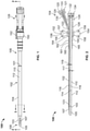
- Figure 1 shows an illustrative dual lumen sheath assembly 100 for maintaining arterial access, according to certain implementations.
- Figure 2 shows a lateral section view of the sheath assembly 100 taken along section line 2-2
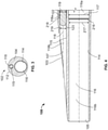
- Figure 3 shows a transverse cross-section of a distal portion of the sheath assembly 100 taken along section line 3-3.
- the sheath assembly 100 includes a tubular sheath body 102, a stylet 120, a hub 126, and a stabilizing structure 150.
- the tubular sheath body 102 is dimensioned for insertion into a blood vessel through a vessel aperture.
- the tubular sheath body 102 is dimensioned for insertion into a femoral artery through an arteriotomy.
- the majority of the tubular sheath body 102 may have a substantially uniform outer diameter 101 of about 10 Fr, 11 Fr, 12 Fr, 13, Fr, 14 Fr, 15 Fr, 16 Fr, 17 Fr, 20 Fr, or any other suitable diameter.
- the tubular sheath body may be dimensioned to be introduced through a percutaneous access site of about 20 Fr (6.67mm) or smaller (e.g., 19 Fr, 18 Fr, 17 Fr, 16 Fr, 15 Fr, 14 Fr, 13 Fr, 12 Fr, 10 Fr, 9 Fr, 8 Fr, 6 Fr, or less).
- the tubular sheath body may have a length of about 80 mm, 100 mm, 120 mm, 140 mm, 160 mm, or any other suitable length.
- the tubular sheath body 102 may be made of a flexible material, such as polyether block amides or any other suitable polymer, to reduce the stress on the blood vessel aperture.
- the tubular sheath body 102 includes a wall 104, a proximal end portion 106, a distal end portion 108, a longitudinal axis 110, an outer surface 112, a first inner surface 114, a second inner surface 115, a first lumen 116, and a second lumen 118.
- the distal end portion 108 of the tubular sheath body 102 includes a tapered surface 103, a first outlet 105 in fluid communication with the first lumen 116, and a second outlet 107 in fluid communication with the second lumen 118.
- the tapered surface 103 has an outer diameter graduated from 11 Fr to 15 Fr (3.667 mm to 5 mm). The graduation in the tapered surface 103 may permit the sheath to be inserted to a variable depth as necessary to plug the gap between the percutaneous pump and the insertion site.
- the outer surface 112 of the tubular sheath body 102 may be coated with a hydrophilic coating to ease insertion of the tubular sheath body 102 into the arteriotomy.
- a hydrophilic coating can also prevent adhesions to the blood vessel wall. Such adhesions could damage the vessel if the sheath is removed after having been in the blood vessel for an extended period of time (e.g., many days). The risk of adhesion to the blood vessel wall can increase as the duration of a procedure increases.
- the outer surface 112 of the tubular sheath body 102 includes depth markings.
- the depth markings may be pad printed or laser etched onto the outer surface 112. In certain implementations, the depth markings are radio-opaque.
- the depth markings may be in centimeters, inches, millimeters, or any other suitable unit of measurement or combination thereof.
- the first inner surface 114 of the tubular sheath body defines the first lumen 116.
- the first lumen 116 is dimensioned to allow passage of a portion of the percutaneous pump.
- the first lumen 116 extends from the proximal end portion 106 of the tubular sheath body 102 to the distal end portion 108, substantially parallel to the longitudinal axis 110.
- the second lumen 118 is disposed within the wall 104 between the inner surface 114 and the outer surface 112. The second lumen 118 extends from the proximal end portion 106 of the tubular sheath body 102 to the distal end portion 108, offset from and substantially parallel to the longitudinal axis 110.
- the second lumen 118 is dimensioned for the passage of a guidewire and is defined by the second inner surface 115 (as shown in Figure 3 ).
- the second inner surface 115 may include a drug or non-drug coating to prevent blood clot formation in the second lumen 118.
- the second inner surface is coated with heparin.
- the second lumen 118 terminates at the second outlet 102 formed in the tapered surface 103.
- the second outlet 102 is adjacent to the first outlet 105 of the first lumen 116.
- the second lumen 118 may be used to maintain or regain guidewire access to the insertion path of a percutaneous pump inserted through the first lumen 116.
- This allows guidewire access to the insertion path to be maintained even after an introducer sheath is removed.
- the guidewire access allows one or more other tools to be subsequently inserted into the same insertion path to facilitate vessel closure or any other medical procedures involving guidewire access.
- the guidewire access may permit the subsequent insertion of a vessel closure tool or a micro pressure measurement catheter (eg., MILLAR Mikro-Tip ® pressure catheter).
- a micro pressure measurement catheter may allow measurement of pressure in the left ventricle or any other suitable pressure.
- the second lumen enables a physician to maintain guidewire access after the introducer sheath is removed, the physician can remove the introducer sheath earlier. Earlier removal of the introducer sheath allows the vessel aperture to recoil to a smaller diameter, thereby reducing the risk of bleeding through the access site.
- the second outlet 107 is offset from the longitudinal axis 110, rotating the tubular sheath body 102 allows the position of the second outlet 107 to be adjusted. This can allow a user to keep the second outlet 107 off of a blood vessel wall to ease insertion of a guidewire or to increase the accuracy of an arterial pressure measurement.
- the tubular sheath body 102 is connected at its proximal end portion 106 to the hub 126.
- the hub 126 includes a first port 128, a second port 130, second port threads 131, and a bearing 136.
- the second port 130 is connected to the second lumen 118 so that a guidewire can be inserted through the second port 130 into the second lumen 118 and out of the second outlet 107.
- the stylet 120 can be inserted into the second port 130 to seal the second lumen 118 (as shown in Figures 1, 2 , and 3 ).
- the stylet 120 includes a head 121, a stylet body 122, a rounded end 123, and threads 126.
- the stylet body 122 is sized to substantially occlude the second lumen 118 when the stylet 120 is inserted into the second lumen 118.
- the stylet body 122 is made of a formable or ductile material, such as a metal. This may allow the stylet to be formed, either during the medical procedure or before, into a shape that reduces stress on the vessel aperture.
- the stylet 120 is radio-opaque or includes radio-opaque marker bands to show the depth of the tubular sheath body 102 in a blood vessel
- the threads 124 of the stylet head 121 reversibly couple with the second port threads 131 to hold the stylet 120 within the second lumen 118.
- a pressure bag is connected to the second port 130 using the threads 131.
- the pressure bag can be used to flush the second lumen 118 with a fluid to maintain the patency of the second lumen 118.
- An infusion pump may be used in combination with the pressure bag to regulate the flow rate of liquid into the patient.
- the flow rate may be limited to 1 mL/hr, 2 mL/hr, 5 mL/hr, 10 mL/hr, or any other suitable flow rate.
- a pressure measuring device is connected to the second port 130 to measure pressure within the vessel 10. This pressure measurement can be used to determine when the second port 102 has been inserted sufficiently deep into the blood vessel aperture. For example, when a pressure about equal to arterial pressure is measured at the second port 130, the second outlet 107 may be in fluid communication with the blood vessel. The pressure measurement can also be used to monitor arterial pressure in the patient's blood vessel during a medical procedure. This may allow an arterial pressure measurement to be taken without the use of an additional catheter, which may reduce the amount of equipment necessary in the potentially crowded operating area.
- the first port 128 of the hub 126 allows the passage of the percutaneous pump (not shown).
- the first port 128 includes a cap 132 and a seal 134.
- the cap 132 snaps into the first port 128 to hold the seal 134 against the first port 128.
- the cap 132 and seal 134 together act as a hemostatic valve and form a liquid tight seal between the percutaneous pump and the first port 128.
- the seal 134 is formed of an elastomer, such as silicone, so that it can flex to seal around a portion of the percutaneous pump.
- the hub 126 is coupled to the stabilizing structure 150 by the bearing 136.
- the stabilizing structure 150 includes wings 152 and 154, suture holes 156-159, ribs 160-162, and a bearing surface 164 that mates with the bearing 136.
- the mating of the bearing surface 164 of the stabilizing structure 150 with the bearing 136 of the hub 126 allows rotation of the hub 126 relative to the stabilizing structure 150. As discussed above, this rotation allows the tubular sheath body 102 to be rotated such that the second outlet 107 is oriented away from a vessel wall. Additionally, this rotation allows the second port 1 30 to lie flat against a patient when the second port 130 is not in use.
- the suture holes 156-159 allow the wings 152 and 154 to be sutured to a patient to stabilize the sheath assembly 100. While only four suture holes 156-159 are shown, any suitable number of suture holes may be used.
- the stabilizing structure 150 is also designed to be easily attached to a vascular graft with umbilical tape or sutures. This feature is beneficial during axillary insertions or any other insertions which require pump placement through a vascular graft. Additionally, in some implementations, the stabilizing structure 150 is coupled to a patient using ribs 160-162. For example, sutures may be wrapped around the outer surface 165 of the stabilizing structure between the ribs 160-162.
- the ribs 160-162 prevent the sutures from sliding off of the outer surface 165 along the longitudinal axis 110.
- other stabilizations devices such as surgical tape, a STATLOCK ® stabilization device (Bard Access Systems, Inc., Salt Lake City, UT), or any other suitable adhesive stabilization device, may be coupled to the stabilizing structure 150 around the ribs 160-162.
- Figure 4 shows a detailed section view of the distal portion 108 of the dual lumen sheath assembly 100 of Figures 1, 2 , and 3 .
- the distal portion 108 includes the tapered surface 103, the first outlet 105, the second outlet 107, and distal portions of the stylet body 122, the first lumen 116, and the second lumen 118.
- the first lumen 116 includes a proximal section 116a having an inner diameter 117, a distal section 116b having an inner diameter 217 which is less than the inner diameter 117, and a restriction 216 therebetween.
- the inner diameter 117 is about 13 Fr (4.333 mm), and the inner diameter 217 is about 9 Fr (3mm).
- the restriction 216 allows the distal section 116b of the first lumen 116 to form a tighter fit with the percutaneous pump to prevent or reduce blood leakage without causing unacceptably high friction in the proximal section 116a.
- the second lumen 118 includes a proximal section 118a having a diameter 119, a distal section 118b having a diameter 219 that is less than the diameter 119, and a restriction 218 therebetween.
- the diameter 119 is about 1.1 mm and the diameter 219 is about 1 mm.
- the restriction 2 18 allows a tighter fit between the stylet body 122 and the second lumen 118 at the distal section 118a to reduce blood ingress, while allowing a clearance in the proximal section 118b to reduce friction.
- the friction between the second lumen 118 and the stylet body 122 is further reduced by the rounding of the end 123 of the stylet body 122.
- the rounded end 123 is located adjacent to the second outlet 107 when the stylet 120 is fully inserted into the second lumen 118, thereby preventing or reducing blood ingress into the second lumen 118.
- FIG. 5 shows the dual lumen sheath assembly 100 of FIG. 1 inserted into a blood vessel 10 of a patient over a percutaneous pump 60.
- the percutaneous pump 60 includes a pump head 66 and a catheter body 62.
- the percutaneous pump 60 may be an intravascular blood pump, a blood pump driven by flexible drive shaft, a blood pump including an implantable motor, a blood pump having an expandable pump rotor, or any other suitable pump.
- the dual lumen sheath assembly 100 is advanced into the blood vessel 10 over the catheter body 62 of the percutaneous pump 60 through the blood vessel aperture 12 in the direction indicated by arrow 70.
- the first lumen 116 of the dual lumen sheath assembly 100 may be threaded on the catheter body 62 when the percutaneous pump 60 is initially inserted into the blood vessel 10.
- the blood vessel 10 may be a femoral artery, and the blood vessel aperture 12 may be an arteriotomy.
- the blood vessel aperture 12 may have an opening slightly larger than the diameter 64 of the catheter body 62.
- the tubular body 102 of the dual lumen sheath assembly 100 may effectively plug the gap between the blood vessel aperture 12 and the catheter by 64 when the sheath assembly 100 is advanced into the blood vessel 10 over the catheter body 62
- the outer diameter 101 of the tubular sheath body 102 may be graduated as discussed above to so that the diameter 101 of the tubular sheath body 102 increases from its distal end portion 108 to its proximal end portion 106. This can allow the tubular sheath body 102 to be inserted farther into the blood vessel 100 to plug a larger gap between the blood vessel aperture 12 and the catheter body 62.
- the plugging effect of the tubular sheath body 102 can reduce or prevent bleeding out of the blood vessel aperture 12.
- the tubular sheath body 102 is flexible so that the tubular sheath body 102 can form a bend 80 which allows the tubular sheath body 102 to follow the contours of the vessel 10. This flexibility can reduce the stress placed on the blood vessel aperture 12 by reducing the force required to deform the tubular sheath body 102.
- the dual lumen sheath assembly 100 may be fixed relative to the catheter body 62. This fixation may be achieved by fixing the stabilizing structure 150 to the patient's tissue 14. In some implementations, this is achieved by suturing wings (not shown) of the stabilizing structure 150 to the patient tissue 14. In certain implementations, the stabilizing structure 150 is attached to a vascular graft with umbilical tape or sutures. This may be performed during axillary insertions or any other insertions which require pump placement through a vascular graft.
- fixing the placement of the dual lumen sheath assembly 100 may be achieved by tightening the seal 134 around the catheter body 62 or by means of a separate anchoring ring.
- the second port 130 may be rotated relative to the stabilizing structure 150 so that the second port 130 lies flat against the patient tissue 14.
- a physician may begin operation of the percutaneous pump 60.
- the percutaneous pump 60 may be operated during a percutaneous coronary intervention (PCI), open-heart surgery, heart valve replacement surgery, or during treatment of acute myocardial infarction (AMI), cardiogenic shock, or ST segment elevation myocardial infarction (STEMI), as well as any other suitable medical procedure.
- PCI percutaneous coronary intervention
- AMI acute myocardial infarction
- STEMI ST segment elevation myocardial infarction
- the percutaneous pump 60 is operated for an extended period of time, such as greater than six hours, greater than 12 hours, greater than 24 hours, greater than 48 hours, greater than 72 hours, greater than one week, or any other suitable duration of time.
- a stylet (not shown in Figure 5 ), such as the stylet 120 from Figures 1-4 , may be positioned within the second lumen 118 during insertion of the dual lumen sheath assembly 100 to prevent blood ingress into the second lumen 118, which could lead to clotting that could obstruct the second lumen 118 or to bleeding out of the second port 130.
- the second port 130 of the dual lumen sheath assembly 100 is used to deliver contrast media (e.g. iodine or barium compounds) into a blood vessel to visualize blood flow.
- contrast media e.g. iodine or barium compounds
- a pressure bag is connected to the second port 130 in place of the stylet to maintain the patency of the second lumen 118.
- An infusion pump may be used in combination with the pressure bag to regulate the flow rate of liquid into the patient.
- the flow rate may be limited to 1 mL/hr, 2 mL/hr, 5 mL/hr, 10 mL/hr, or any other suitable flow rate.
- a pressure measuring device is connected to the second port 130 to measure the pressure within the vessel 10. This pressure measurement can be used to determine when the second port 102 has been inserted sufficiently deep into the blood vessel aperture 12.
- the second outlet 107 may be in fluid communication with the blood vessel 10.
- the depth of the blood vessel aperture 12 relative to the patient's skin can be measured using depth markings disposed on an outer surface of the sheath. The measurement of this depth can facilitate the subsequent use of certain vessel closure tools which may require such a measurement.
- the pressure measurement can also be used to monitor arterial pressure in the blood vessel 10 during a medical procedure. This may allow an arterial pressure measurement to be taken without the use of an additional catheter, which may reduce the amount of equipment necessary in the potentially crowded operating area.
- the second lumen 118 can allow a determination of the depth of insertion without a pressure transducer by allowing observation of the onset of blood flow through the second lumen 118 ("bleedback"), which is indicative of penetration into the blood vessel aperture 12.
- a guidewire 50 is inserted through the second port 130 into the second lumen 118 and out the second outlet 107 into the blood vessel 10.
- the guidewire 50 enters the same insertion path as the percutaneous pump 60, thereby maintaining access to the insertion path.
- a stylet was used during insertion of the dual lumen sheath assembly 100, the stylet is removed before insertion of the guidewire 50.
- the guidewire 50 has an outer diameter that approximately matches the inner diameter of the second outlet 107 to prevent blood from flowing out of the blood vessel 10 through the second port 130.
- the guidewire may have an outer diameter of about 1 mm.
- a seal at the second port 130 is included to further ensure that no blood exits the second port 130 while the guidewire 50 is in place.
- the percutaneous pump 60 and the dual lumen sheath assembly 100 may be removed through the blood vessel aperture 12 while the guidewire 50 is left in place.
- the tubular sheath body 102 may be coated with a hydrophilic coating or any other suitable coating that prevents adhesions to the blood vessel 10, thereby facilitating removal of the tubular sheath body 102 without damaging the blood vessel 10.
- the removal of the dual lumen sheath assembly 100 and percutaneous pump 60 while the guidewire 50 is left in place allows guidewire access to the insertion path 11 to be maintained.
- the removal of the percutaneous pump 60 requires the concurrent removal of the dual lumen sheath assembly 100 because the diameter 68 of the pump head 66 cannot pass through the first lumen 116.
- the inner diameter of the first lumen 116 is sized to fit tightly around the diameter 64 of the catheter body 62, but cannot accommodate the larger diameter 68 of the pump head 66. As a result, the first lumen 116 is not available to be used to maintain guidewire access to the insertion path 11. Thus, the second lumen 118 is necessary to maintain guidewire access to the insertion path 11.
- a vascular closure device is inserted into the insertion path 11 using the guidewire 50.
- the vascular closure device may be the VASOSEAL vascular sealing device, the ANGIO-SEAL bio-absorbable active closure system, the PERCLOSE vascular sealing device, or any other suitable vascular closure device or combination of vascular closure devices.
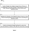
- FIG. 6 shows an illustrative process 600, which does not form part of the invention, for maintaining guidewire access.
- the illustrative process 600 may be performed using the dual lumen sheath assembly 100 or any other suitable sheath tool.
- a sheath is inserted into a blood vessel through a percutaneous insertion path and along a portion of a percutaneous pump.
- the sheath has a first lumen and a second lumen.
- the blood vessel may be an artery, such as the femoral artery.
- the insertion path passes through a blood vessel aperture (e.g., an arteriotomy).
- the percutaneous pump is inserted into the insertion path using an introducer prior to step 602. Therefore, the percutaneous pump guides the sheath into the existing insertion path.
- the percutaneous pump may be an intravascular blood pump, a blood pump driven by flexible drive shaft, a blood pump including an implantable motor, a blood pump having an expandable pump rotor, or any other suitable pump.
- the first lumen of the sheath may be sealed against the percutaneous pump by a hemostatic valve to prevent leakage of blood from the blood vessel out of the patient.
- the sheath is only inserted into the vessel as deep as is necessary to close the gap between the percutaneous pump and the vessel aperture to prevent bleeding.
- the pressure within the vessel can be detected using the second lumen. For example, a detected pressure about equal to arterial pressure may indicate that the outlet of the second lumen has been inserted into the blood vessel.
- the second lumen can allow a determination of the depth of insertion without a pressure transducer by allowing observation of the onset of blood flow? through the second lumen ("bleedback"), which is indicative of penetration into the blood vessel aperture.
- the depth of the blood vessel aperture relative to the patient's skin can be measured using depth markings disposed on an outer surface of the sheath.
- the depth markings are radio-opaque and can be imaged using a tomographic imaging modality (e.g., CT, MRI, X-ray). The measurement of this depth can facilitate the subsequent use of certain vessel closure tools which may require such a measurement.
- the second lumen can be used to measure arterial pressure during the procedure.
- the sheath is maintained in the vessel for about six hours or more while blood clot formation is prevented from occluding the second lumen.
- the sheath may be maintained in the vessel for 6 hours, 12 hours, 24 hours, 48 hours, 72 hours, one week, two weeks, or any other suitable duration of time.
- Blood clot formation in the second lumen may be prevented during this time using a stylet that temporarily occludes the second lumen.
- the stylet 120 of Figures 1-3 may be used to temporarily occlude the second lumen.
- blood clot formation in the second lumen is prevented or reduced using a drug or nondrug coating in the second lumen.
- the coating may include heparin or any other suitable substance.
- blood clot formation in the second lumen is prevented or reduced by flushing the second lumen with a liquid (e.g., saline solution, glucose solution, or any other suitable solution).
- a liquid e.g., saline solution, glucose solution, or any other suitable solution.
- a guidewire is inserted through the second lumen into the percutaneous insertion path after the about six hours or more. If a stylet was used to temporarily occlude the second lumen, the stylet is removed before inserting the guidewire.
- the percutaneous pump inserted through the first lumen may be removed after insertion of the guidewire.
- the sheath may be removed from the percutaneous insertion path while the guidewire remains in place. This can allow another tool (e.g., an access closure tool) to be inserted into the insertion path.
- an access closure tool e.g., an access closure tool
- the physician is able to remove the introducer earlier in a procedure. This can allow greater recoil of the blood vessel aperture, thereby reducing the risk of bleeding. For example, removing the introducer within an hour of insertion may allow a recoil of about 2 to 3 Fr (0.667 mm to 1 mm).
- the sheath assembly may be used to provide guidewire access for procedures of a short duration (e.g., less than six hours).
Landscapes
- Health & Medical Sciences (AREA)
- Heart & Thoracic Surgery (AREA)
- Engineering & Computer Science (AREA)
- Life Sciences & Earth Sciences (AREA)
- Animal Behavior & Ethology (AREA)
- Veterinary Medicine (AREA)
- Public Health (AREA)
- General Health & Medical Sciences (AREA)
- Anesthesiology (AREA)
- Biomedical Technology (AREA)
- Hematology (AREA)
- Cardiology (AREA)
- Mechanical Engineering (AREA)
- Vascular Medicine (AREA)
- Biophysics (AREA)
- Pulmonology (AREA)
- Transplantation (AREA)
- Media Introduction/Drainage Providing Device (AREA)
- External Artificial Organs (AREA)
- Farming Of Fish And Shellfish (AREA)
- Measurement Of The Respiration, Hearing Ability, Form, And Blood Characteristics Of Living Organisms (AREA)
Priority Applications (1)
| Application Number | Priority Date | Filing Date | Title |
|---|---|---|---|
| EP22161299.7A EP4032577A1 (en) | 2015-08-17 | 2016-08-17 | Dual lumen sheath for arterial access |
Applications Claiming Priority (2)
| Application Number | Priority Date | Filing Date | Title |
|---|---|---|---|
| US14/827,741 US10737008B2 (en) | 2015-08-17 | 2015-08-17 | Dual lumen sheath for arterial access |
| PCT/US2016/047421 WO2017031243A1 (en) | 2015-08-17 | 2016-08-17 | Dual lumen sheath for arterial access |
Related Child Applications (1)
| Application Number | Title | Priority Date | Filing Date |
|---|---|---|---|
| EP22161299.7A Division EP4032577A1 (en) | 2015-08-17 | 2016-08-17 | Dual lumen sheath for arterial access |
Publications (3)
| Publication Number | Publication Date |
|---|---|
| EP3337530A1 EP3337530A1 (en) | 2018-06-27 |
| EP3337530A4 EP3337530A4 (en) | 2019-04-10 |
| EP3337530B1 true EP3337530B1 (en) | 2022-03-16 |
Family
ID=58051709
Family Applications (2)
| Application Number | Title | Priority Date | Filing Date |
|---|---|---|---|
| EP16837779.4A Active EP3337530B1 (en) | 2015-08-17 | 2016-08-17 | Dual lumen sheath for arterial access |
| EP22161299.7A Pending EP4032577A1 (en) | 2015-08-17 | 2016-08-17 | Dual lumen sheath for arterial access |
Family Applications After (1)
| Application Number | Title | Priority Date | Filing Date |
|---|---|---|---|
| EP22161299.7A Pending EP4032577A1 (en) | 2015-08-17 | 2016-08-17 | Dual lumen sheath for arterial access |
Country Status (12)
| Country | Link |
|---|---|
| US (5) | US10737008B2 (enExample) |
| EP (2) | EP3337530B1 (enExample) |
| JP (5) | JP6851114B2 (enExample) |
| KR (5) | KR20250024855A (enExample) |
| CN (1) | CN210698360U (enExample) |
| AU (3) | AU2016308193B2 (enExample) |
| BR (1) | BR112018003164B1 (enExample) |
| CA (2) | CA3224423A1 (enExample) |
| DK (1) | DK3337530T3 (enExample) |
| ES (1) | ES2909848T3 (enExample) |
| IL (6) | IL296370B2 (enExample) |
| WO (1) | WO2017031243A1 (enExample) |
Families Citing this family (46)
| Publication number | Priority date | Publication date | Assignee | Title |
|---|---|---|---|---|
| US10737008B2 (en) * | 2015-08-17 | 2020-08-11 | Abiomed, Inc. | Dual lumen sheath for arterial access |
| AU2018280236B2 (en) | 2017-06-07 | 2024-06-06 | Supira Medical, Inc. | Intravascular fluid movement devices, systems, and methods of use |
| SG11201912175UA (en) * | 2017-06-28 | 2020-01-30 | Abiomed Inc | Guidewire access sleeve |
| EP3681553A2 (en) * | 2017-09-14 | 2020-07-22 | Abiomed, Inc. | Integrated expandable access for medical device introducer |
| WO2019094963A1 (en) | 2017-11-13 | 2019-05-16 | Shifamed Holdings, Llc | Intravascular fluid movement devices, systems, and methods of use |
| DE102018201030B4 (de) | 2018-01-24 | 2025-10-16 | Kardion Gmbh | Magnetkuppelelement mit magnetischer Lagerungsfunktion |
| CN117959583A (zh) | 2018-02-01 | 2024-05-03 | 施菲姆德控股有限责任公司 | 血管内血泵以及使用和制造方法 |
| BR112020016424B1 (pt) * | 2018-02-26 | 2023-10-17 | Cti Vascular Ag | Cateter selecionável por comprimento útil para tratar patologias vasculares |
| US11167121B2 (en) * | 2018-05-15 | 2021-11-09 | Cardiovascular Systems, Inc. | Intravascular pump with integrated isolated conductor(s) and methods thereof |
| DE102018207611A1 (de) | 2018-05-16 | 2019-11-21 | Kardion Gmbh | Rotorlagerungssystem |
| DE102018207575A1 (de) | 2018-05-16 | 2019-11-21 | Kardion Gmbh | Magnetische Stirndreh-Kupplung zur Übertragung von Drehmomenten |
| DE102018208549A1 (de) | 2018-05-30 | 2019-12-05 | Kardion Gmbh | Elektronikmodul für ein Herzunterstützungssystem und Verfahren zum Herstellen eines Elektronikmoduls für ein Herzunterstützungssystem |
| DE102018208550A1 (de) | 2018-05-30 | 2019-12-05 | Kardion Gmbh | Leitungsvorrichtung zum Leiten eines Blutstroms für ein Herzunterstützungssystem, Herzunterstützungssystem und Verfahren zum Herstellen einer Leitungsvorrichtung |
| DE102018208555A1 (de) | 2018-05-30 | 2019-12-05 | Kardion Gmbh | Vorrichtung zum Verankern eines Herzunterstützungssystems in einem Blutgefäß, Verfahren zum Betreiben und Herstellverfahren zum Herstellen einer Vorrichtung und Herzunterstützungssystem |
| DE102018208539A1 (de) | 2018-05-30 | 2019-12-05 | Kardion Gmbh | Motorgehäusemodul zum Abdichten eines Motorraums eines Motors eines Herzunterstützungssystems und Herzunterstützungssystem und Verfahren zum Montieren eines Herzunterstützungssystems |
| DE102018208541A1 (de) | 2018-05-30 | 2019-12-05 | Kardion Gmbh | Axialpumpe für ein Herzunterstützungssystem und Verfahren zum Herstellen einer Axialpumpe für ein Herzunterstützungssystem |
| DE102018208538A1 (de) | 2018-05-30 | 2019-12-05 | Kardion Gmbh | Intravasale Blutpumpe und Verfahren zur Herstellung von elektrischen Leiterbahnen |
| DE102018210058A1 (de) | 2018-06-21 | 2019-12-24 | Kardion Gmbh | Statorschaufelvorrichtung zur Strömungsführung eines aus einer Austrittsöffnung eines Herzunterstützungssystems ausströmenden Fluids, Herzunterstützungssystem mit Statorschaufelvorrichtung, Verfahren zum Betreiben einer Statorschaufelvorrichtung und Herstellverfahren |
| DE102018210076A1 (de) | 2018-06-21 | 2019-12-24 | Kardion Gmbh | Verfahren und Vorrichtung zum Erkennen eines Verschleißzustands eines Herzunterstützungssystems, Verfahren und Vorrichtung zum Betreiben eines Herzunterstützungssystems und Herzunterstützungssystem |
| DE102018211297A1 (de) | 2018-07-09 | 2020-01-09 | Kardion Gmbh | Herzunterstützungssystem und Verfahren zur Überwachung der Integrität einer Haltestruktur eines Herzunterstützungssystems |
| DE102018211327A1 (de) | 2018-07-10 | 2020-01-16 | Kardion Gmbh | Laufrad für ein implantierbares, vaskuläres Unterstützungssystem |
| DE102018211328A1 (de) | 2018-07-10 | 2020-01-16 | Kardion Gmbh | Laufradgehäuse für ein implantierbares, vaskuläres Unterstützungssystem |
| DE102018212153A1 (de) | 2018-07-20 | 2020-01-23 | Kardion Gmbh | Zulaufleitung für eine Pumpeneinheit eines Herzunterstützungssystems, Herzunterstützungssystem und Verfahren zum Herstellen einer Zulaufleitung für eine Pumpeneinheit eines Herzunterstützungssystems |
| WO2020028537A1 (en) | 2018-07-31 | 2020-02-06 | Shifamed Holdings, Llc | Intravascaular blood pumps and methods of use |
| AU2019320533B2 (en) | 2018-08-07 | 2024-11-21 | Kardion Gmbh | Bearing device for a cardiac support system, and method for flushing an intermediate space in a bearing device for a cardiac support system |
| EP3860675A4 (en) | 2018-10-05 | 2022-07-13 | Shifamed Holdings, LLC | INTRAVASCULAR BLOOD PUMPS AND METHODS OF USE |
| EP4162973A1 (en) * | 2018-10-18 | 2023-04-12 | Abiomed, Inc. | Systems and methods for minimizing leaks during insertion of pumps |
| EP3897801A2 (en) * | 2018-12-21 | 2021-10-27 | Abiomed, Inc. | Persistent perfusion sheath |
| US12042170B2 (en) | 2019-05-12 | 2024-07-23 | EvolutionMedVentures LLC | Add-on sheath |
| EP3996797A4 (en) | 2019-07-12 | 2023-08-02 | Shifamed Holdings, LLC | INTRAVASCULAR BLOOD PUMPS AND METHOD OF USE AND METHOD OF MAKING |
| WO2021016372A1 (en) | 2019-07-22 | 2021-01-28 | Shifamed Holdings, Llc | Intravascular blood pumps with struts and methods of use and manufacture |
| EP4010046A4 (en) | 2019-08-07 | 2023-08-30 | Calomeni, Michael | Catheter blood pumps and collapsible pump housings |
| EP4034192A4 (en) | 2019-09-25 | 2023-11-29 | Shifamed Holdings, LLC | INTRAVASCULAR BLOOD PUMP DEVICES AND SYSTEMS AND METHODS OF USE AND CONTROL THEREOF |
| US12102815B2 (en) | 2019-09-25 | 2024-10-01 | Shifamed Holdings, Llc | Catheter blood pumps and collapsible pump housings |
| US12121713B2 (en) | 2019-09-25 | 2024-10-22 | Shifamed Holdings, Llc | Catheter blood pumps and collapsible blood conduits |
| WO2021119478A1 (en) | 2019-12-11 | 2021-06-17 | Shifamed Holdings, Llc | Descending aorta and vena cava blood pumps |
| DE102020102474A1 (de) | 2020-01-31 | 2021-08-05 | Kardion Gmbh | Pumpe zum Fördern eines Fluids und Verfahren zum Herstellen einer Pumpe |
| TW202533848A (zh) | 2020-02-03 | 2025-09-01 | 美商阿比奥梅德公司 | 具延展護套的設備 |
| ES2926596T3 (es) * | 2020-05-28 | 2022-10-27 | Medinice S A | Cánula para canulación percutánea mínimamente invasiva de la vena cava |
| JP6851533B1 (ja) * | 2020-06-10 | 2021-03-31 | ガデリウス・メディカル株式会社 | 造影剤注入用カテーテル |
| JP2023550349A (ja) | 2020-11-15 | 2023-12-01 | エボリューションメドベンチャーズ リミティド ライアビリティ カンパニー | シースの段階的拡張部 |
| AU2022390146B2 (en) | 2021-11-17 | 2025-04-03 | Boston Scientific Scimed Inc. | Device housing features to facilitate damage free guidewire translations |
| CN116637294A (zh) * | 2023-05-09 | 2023-08-25 | 深圳核心医疗科技股份有限公司 | 防出血结构及血泵系统 |
| WO2025085520A1 (en) * | 2023-10-20 | 2025-04-24 | Boston Scientific Scimed, Inc. | Mechanical circulatory support system with repositioning sheath |
| US20250235595A1 (en) * | 2024-01-18 | 2025-07-24 | Inspire M.D Ltd. | Intravascular sheath |
| CN119971300B (zh) * | 2025-03-17 | 2025-11-28 | 生命盾医疗技术(苏州)有限公司 | 用于将导管泵引入受试者体内的护套组件 |
Family Cites Families (62)
| Publication number | Priority date | Publication date | Assignee | Title |
|---|---|---|---|---|
| US4137916A (en) | 1976-11-22 | 1979-02-06 | Travenol Laboratories, Inc. | Catheter plug assembly |
| US4180068A (en) | 1978-04-13 | 1979-12-25 | Motion Control, Incorporated | Bi-directional flow catheter with retractable trocar/valve structure |
| US4643711A (en) * | 1984-05-25 | 1987-02-17 | Cook, Inc. | Two lumen hemodialysis catheter |
| JPS61199867A (ja) * | 1985-02-28 | 1986-09-04 | バイオメデイカル株式会社 | 血管内留置カテ−テル |
| US4699611A (en) | 1985-04-19 | 1987-10-13 | C. R. Bard, Inc. | Biliary stent introducer |
| US4995863A (en) | 1986-10-06 | 1991-02-26 | Catheter Technology Corporation | Catheter with slit valve |
| DE3831464A1 (de) | 1988-09-16 | 1990-03-29 | Hoechst Ag | Verfahren zum alkali-freien faerben und bedrucken von cellulosefasern |
| US5234425A (en) | 1989-03-03 | 1993-08-10 | Thomas J. Fogarty | Variable diameter sheath method and apparatus for use in body passages |
| US5273527A (en) * | 1992-05-12 | 1993-12-28 | Ovamed Corporation | Delivery catheter |
| US5139486A (en) | 1991-01-02 | 1992-08-18 | Gerald Moss | Dilator/introducer for percutaneous gastrostomy |
| WO1993006878A1 (en) | 1991-10-11 | 1993-04-15 | Boston Scientific Corporation | Catheter introducer sheath assembly |
| US5935122A (en) | 1991-12-13 | 1999-08-10 | Endovascular Technologies, Inc. | Dual valve, flexible expandable sheath and method |
| US5395349A (en) | 1991-12-13 | 1995-03-07 | Endovascular Technologies, Inc. | Dual valve reinforced sheath and method |
| US5304142A (en) | 1992-08-04 | 1994-04-19 | Medamicus, Inc. | Dilator - Introducer locking hub and sheath valve apparatus |
| US6338730B1 (en) | 1993-02-04 | 2002-01-15 | Peter M. Bonutti | Method of using expandable cannula |
| US5320611A (en) | 1993-02-04 | 1994-06-14 | Peter M. Bonutti | Expandable cannula having longitudinal wire and method of use |
| US5431639A (en) * | 1993-08-12 | 1995-07-11 | Boston Scientific Corporation | Treating wounds caused by medical procedures |
| US5492530A (en) | 1994-02-07 | 1996-02-20 | Cathco, Inc. | Method for accessing the coronary arteries from the radial or brachial artery in the arm |
| US5407430A (en) | 1994-03-21 | 1995-04-18 | Peters; Michael J. | Intravenous catheter |
| US5395341A (en) | 1994-03-21 | 1995-03-07 | Cordis Corporation | One piece vessel dilator/catheter sheath introducer |
| US5488960A (en) | 1994-04-11 | 1996-02-06 | Abbott Laboratories | Coronary sinus catheter introducer system |
| US5536255A (en) | 1994-10-03 | 1996-07-16 | Moss; Gerald | Dilator/introducer apparatus for percutaneous gastrostomy |
| US5971993A (en) | 1996-11-07 | 1999-10-26 | Myocardial Stents, Inc. | System for delivery of a trans myocardial device to a heart wall |
| US5911702A (en) | 1997-11-06 | 1999-06-15 | Heartport, Inc. | Methods and devices for cannulating a patient's blood vessel |
| US6692462B2 (en) | 1999-05-19 | 2004-02-17 | Mackenzie Andrew J. | System and method for establishing vascular access |
| US6607547B1 (en) | 1999-08-25 | 2003-08-19 | Origin Medsystems, Inc. | Longitudinal dilator and method |
| US20060287574A1 (en) | 1999-08-25 | 2006-12-21 | Chin Albert K | Longitudinal dilator |
| EP1207934B1 (en) | 1999-09-03 | 2014-08-06 | A-Med Systems, Inc. | Guidable intravascular blood pump |
| US6814718B2 (en) * | 2001-01-09 | 2004-11-09 | Rex Medical, L.P | Dialysis catheter |
| ATE459388T1 (de) | 2001-12-26 | 2010-03-15 | Univ Yale | Gefäss-shuntvorrichtung |
| JP3942465B2 (ja) | 2002-03-22 | 2007-07-11 | 住友ベークライト株式会社 | 留置カテーテル |
| US8509916B2 (en) | 2002-12-16 | 2013-08-13 | Medtronic, Inc. | Bilumen guide catheters for accessing cardiac sites |
| US7037290B2 (en) | 2002-12-16 | 2006-05-02 | Medtronic, Inc. | Multi-lumen steerable catheter |
| JP4691640B2 (ja) | 2003-10-03 | 2011-06-01 | メドトロニック,インコーポレイテッド | 膨張可能なシースおよび装置ならびにその製造方法 |
| JP2005287670A (ja) * | 2004-03-31 | 2005-10-20 | Nipro Corp | 血管内留置カテーテル |
| JP4938668B2 (ja) | 2004-09-09 | 2012-05-23 | オンセット メディカル コーポレイション | 拡張可能な経腔的シース |
| WO2006074044A2 (en) | 2004-12-30 | 2006-07-13 | Neomend, Inc. | Method and apparatus for percutaneous wound sealing |
| ES2377076T3 (es) | 2005-07-19 | 2012-03-22 | Zvi Ben Shalom | Sistema de asistencia para órganos |
| JP5111767B2 (ja) * | 2006-02-03 | 2013-01-09 | ユニチカ株式会社 | トリプルルーメンカテーテル |
| ATE531417T1 (de) | 2006-04-21 | 2011-11-15 | Abbott Lab | Vorrichtung zur führungsdrahtpositionierung |
| US20080051821A1 (en) | 2006-08-22 | 2008-02-28 | Gephart Matthew P | Tissue dilation tool and method of dilating tissue |
| JP5106537B2 (ja) | 2006-09-28 | 2012-12-26 | ハート リーフレット テクノロジーズ, インコーポレイテッド | プロテーゼの経皮的送達のための送達ツール |
| US8317773B2 (en) | 2006-11-07 | 2012-11-27 | Angio Dynamics, Inc. | Catheter with open faced sloped end portion |
| US8292841B2 (en) | 2007-10-26 | 2012-10-23 | C. R. Bard, Inc. | Solid-body catheter including lateral distal openings |
| WO2009131612A1 (en) | 2008-03-21 | 2009-10-29 | William Joseph Drasler | Expandable introducer sheath |
| US8231519B2 (en) | 2009-05-20 | 2012-07-31 | Thoratec Corporation | Multi-lumen cannula |
| JP5815516B2 (ja) | 2009-07-01 | 2015-11-17 | ザ・ペン・ステイト・リサーチ・ファウンデイションThe Penn State Research Foundation | 拡張可能なカニューレを備える血液ポンプ |
| US20110040241A1 (en) | 2009-08-11 | 2011-02-17 | Dongfang Wang | Blood access assembly for artificial lung and right ventricular assist device |
| US8562519B2 (en) * | 2009-12-31 | 2013-10-22 | Cardiacassist, Inc. | Pumping system and method for assisting a patient's heart |
| US20110319728A1 (en) | 2010-06-29 | 2011-12-29 | Edwards Lifesciences Corporation | Blood parameter sensor and flow control system, method and computer program product |
| US9180274B2 (en) * | 2010-09-09 | 2015-11-10 | W. L. G ore & Associates, Inc | Indwelling luminal devices |
| US8758402B2 (en) | 2010-12-17 | 2014-06-24 | Boston Scientific Scimed, Inc. | Tissue puncture closure device |
| US20170112480A9 (en) | 2010-12-17 | 2017-04-27 | Boston Scientific Scimed, Inc. | Expandable device sheath for vascular closure plug deployment |
| JP5936093B2 (ja) | 2011-05-02 | 2016-06-15 | ニプロ株式会社 | ダブルルーメンダイレータ |
| JP2012249732A (ja) | 2011-06-01 | 2012-12-20 | Univ Of Tokyo | カニューレおよび補助循環装置 |
| US9168352B2 (en) * | 2011-12-19 | 2015-10-27 | Cardiacassist, Inc. | Dual lumen cannula |
| EP2606920A1 (de) * | 2011-12-22 | 2013-06-26 | ECP Entwicklungsgesellschaft mbH | Schleuseneinrichtung zum Einführen eines Katheters |
| US20130317438A1 (en) | 2012-05-25 | 2013-11-28 | Arstasis, Inc. | Vascular access configuration |
| US20130317481A1 (en) | 2012-05-25 | 2013-11-28 | Arstasis, Inc. | Vascular access configuration |
| US20150051635A1 (en) | 2013-08-14 | 2015-02-19 | Zoll Circulation, Inc. | Aortic occluder with strength bonded balloons |
| US10258768B2 (en) * | 2014-07-14 | 2019-04-16 | C. R. Bard, Inc. | Apparatuses, systems, and methods for inserting catheters having enhanced stiffening and guiding features |
| US10737008B2 (en) * | 2015-08-17 | 2020-08-11 | Abiomed, Inc. | Dual lumen sheath for arterial access |
-
2015
- 2015-08-17 US US14/827,741 patent/US10737008B2/en active Active
-
2016
- 2016-08-17 CA CA3224423A patent/CA3224423A1/en active Pending
- 2016-08-17 IL IL296370A patent/IL296370B2/en unknown
- 2016-08-17 KR KR1020257002714A patent/KR20250024855A/ko active Pending
- 2016-08-17 EP EP16837779.4A patent/EP3337530B1/en active Active
- 2016-08-17 CN CN201690001274.5U patent/CN210698360U/zh active Active
- 2016-08-17 KR KR1020187007479A patent/KR102381615B1/ko active Active
- 2016-08-17 JP JP2018508747A patent/JP6851114B2/ja active Active
- 2016-08-17 AU AU2016308193A patent/AU2016308193B2/en active Active
- 2016-08-17 DK DK16837779.4T patent/DK3337530T3/da active
- 2016-08-17 EP EP22161299.7A patent/EP4032577A1/en active Pending
- 2016-08-17 KR KR1020237032316A patent/KR102677705B1/ko active Active
- 2016-08-17 IL IL308629A patent/IL308629B2/en unknown
- 2016-08-17 KR KR1020247020254A patent/KR102761568B1/ko active Active
- 2016-08-17 KR KR1020227010207A patent/KR102582830B1/ko active Active
- 2016-08-17 IL IL302844A patent/IL302844B2/en unknown
- 2016-08-17 ES ES16837779T patent/ES2909848T3/es active Active
- 2016-08-17 WO PCT/US2016/047421 patent/WO2017031243A1/en not_active Ceased
- 2016-08-17 CA CA2995707A patent/CA2995707C/en active Active
- 2016-08-17 IL IL312920A patent/IL312920A/en unknown
- 2016-08-17 BR BR112018003164-0A patent/BR112018003164B1/pt active IP Right Grant
-
2018
- 2018-02-15 IL IL257546A patent/IL257546B/en unknown
-
2020
- 2020-06-22 US US16/907,533 patent/US20200324034A1/en not_active Abandoned
-
2021
- 2021-03-04 JP JP2021034186A patent/JP7169386B2/ja active Active
- 2021-06-18 US US17/351,671 patent/US11833314B2/en active Active
- 2021-06-30 AU AU2021204533A patent/AU2021204533B2/en active Active
- 2021-08-19 IL IL285740A patent/IL285740B2/en unknown
-
2022
- 2022-10-28 JP JP2022172912A patent/JP7401629B2/ja active Active
-
2023
- 2023-10-18 US US18/381,219 patent/US12239799B2/en active Active
- 2023-11-28 AU AU2023274093A patent/AU2023274093B2/en active Active
- 2023-12-07 JP JP2023206608A patent/JP7573090B2/ja active Active
-
2024
- 2024-10-11 JP JP2024178605A patent/JP2025013357A/ja active Pending
-
2025
- 2025-02-14 US US19/053,650 patent/US20250256063A1/en active Pending
Non-Patent Citations (1)
| Title |
|---|
| None * |
Also Published As
Similar Documents
| Publication | Publication Date | Title |
|---|---|---|
| US12239799B2 (en) | Dual lumen sheath for arterial access | |
| HK40076917A (en) | Dual lumen sheath for arterial access |
Legal Events
| Date | Code | Title | Description |
|---|---|---|---|
| STAA | Information on the status of an ep patent application or granted ep patent |
Free format text: STATUS: THE INTERNATIONAL PUBLICATION HAS BEEN MADE |
|
| PUAI | Public reference made under article 153(3) epc to a published international application that has entered the european phase |
Free format text: ORIGINAL CODE: 0009012 |
|
| STAA | Information on the status of an ep patent application or granted ep patent |
Free format text: STATUS: REQUEST FOR EXAMINATION WAS MADE |
|
| 17P | Request for examination filed |
Effective date: 20180312 |
|
| AK | Designated contracting states |
Kind code of ref document: A1 Designated state(s): AL AT BE BG CH CY CZ DE DK EE ES FI FR GB GR HR HU IE IS IT LI LT LU LV MC MK MT NL NO PL PT RO RS SE SI SK SM TR |
|
| AX | Request for extension of the european patent |
Extension state: BA ME |
|
| DAV | Request for validation of the european patent (deleted) | ||
| DAX | Request for extension of the european patent (deleted) | ||
| A4 | Supplementary search report drawn up and despatched |
Effective date: 20190313 |
|
| RIC1 | Information provided on ipc code assigned before grant |
Ipc: A61M 1/12 20060101ALI20190306BHEP Ipc: A61M 1/10 20060101AFI20190306BHEP Ipc: A61M 25/00 20060101ALI20190306BHEP Ipc: A61M 5/14 20060101ALI20190306BHEP |
|
| STAA | Information on the status of an ep patent application or granted ep patent |
Free format text: STATUS: EXAMINATION IS IN PROGRESS |
|
| 17Q | First examination report despatched |
Effective date: 20201014 |
|
| REG | Reference to a national code |
Ref country code: DE Ref legal event code: R079 Ref document number: 602016070130 Country of ref document: DE Free format text: PREVIOUS MAIN CLASS: A61M0001100000 Ipc: A61M0025000000 |
|
| RIC1 | Information provided on ipc code assigned before grant |
Ipc: A61M 60/205 20210101ALI20210806BHEP Ipc: A61M 60/148 20210101ALI20210806BHEP Ipc: A61M 60/135 20210101ALI20210806BHEP Ipc: A61M 25/06 20060101ALI20210806BHEP Ipc: A61M 25/02 20060101ALI20210806BHEP Ipc: A61M 25/01 20060101ALI20210806BHEP Ipc: A61M 25/00 20060101AFI20210806BHEP |
|
| GRAP | Despatch of communication of intention to grant a patent |
Free format text: ORIGINAL CODE: EPIDOSNIGR1 |
|
| STAA | Information on the status of an ep patent application or granted ep patent |
Free format text: STATUS: GRANT OF PATENT IS INTENDED |
|
| INTG | Intention to grant announced |
Effective date: 20211006 |
|
| GRAS | Grant fee paid |
Free format text: ORIGINAL CODE: EPIDOSNIGR3 |
|
| GRAA | (expected) grant |
Free format text: ORIGINAL CODE: 0009210 |
|
| STAA | Information on the status of an ep patent application or granted ep patent |
Free format text: STATUS: THE PATENT HAS BEEN GRANTED |
|
| AK | Designated contracting states |
Kind code of ref document: B1 Designated state(s): AL AT BE BG CH CY CZ DE DK EE ES FI FR GB GR HR HU IE IS IT LI LT LU LV MC MK MT NL NO PL PT RO RS SE SI SK SM TR |
|
| REG | Reference to a national code |
Ref country code: GB Ref legal event code: FG4D |
|
| REG | Reference to a national code |
Ref country code: CH Ref legal event code: EP Ref country code: DE Ref legal event code: R096 Ref document number: 602016070130 Country of ref document: DE |
|
| REG | Reference to a national code |
Ref country code: DK Ref legal event code: T3 Effective date: 20220331 |
|
| REG | Reference to a national code |
Ref country code: IE Ref legal event code: FG4D |
|
| REG | Reference to a national code |
Ref country code: AT Ref legal event code: REF Ref document number: 1475452 Country of ref document: AT Kind code of ref document: T Effective date: 20220415 |
|
| REG | Reference to a national code |
Ref country code: SE Ref legal event code: TRGR |
|
| REG | Reference to a national code |
Ref country code: NL Ref legal event code: FP |
|
| REG | Reference to a national code |
Ref country code: ES Ref legal event code: FG2A Ref document number: 2909848 Country of ref document: ES Kind code of ref document: T3 Effective date: 20220510 |
|
| REG | Reference to a national code |
Ref country code: LT Ref legal event code: MG9D |
|
| PG25 | Lapsed in a contracting state [announced via postgrant information from national office to epo] |
Ref country code: RS Free format text: LAPSE BECAUSE OF FAILURE TO SUBMIT A TRANSLATION OF THE DESCRIPTION OR TO PAY THE FEE WITHIN THE PRESCRIBED TIME-LIMIT Effective date: 20220316 Ref country code: NO Free format text: LAPSE BECAUSE OF FAILURE TO SUBMIT A TRANSLATION OF THE DESCRIPTION OR TO PAY THE FEE WITHIN THE PRESCRIBED TIME-LIMIT Effective date: 20220616 Ref country code: LT Free format text: LAPSE BECAUSE OF FAILURE TO SUBMIT A TRANSLATION OF THE DESCRIPTION OR TO PAY THE FEE WITHIN THE PRESCRIBED TIME-LIMIT Effective date: 20220316 Ref country code: HR Free format text: LAPSE BECAUSE OF FAILURE TO SUBMIT A TRANSLATION OF THE DESCRIPTION OR TO PAY THE FEE WITHIN THE PRESCRIBED TIME-LIMIT Effective date: 20220316 Ref country code: BG Free format text: LAPSE BECAUSE OF FAILURE TO SUBMIT A TRANSLATION OF THE DESCRIPTION OR TO PAY THE FEE WITHIN THE PRESCRIBED TIME-LIMIT Effective date: 20220616 |
|
| REG | Reference to a national code |
Ref country code: AT Ref legal event code: MK05 Ref document number: 1475452 Country of ref document: AT Kind code of ref document: T Effective date: 20220316 |
|
| PG25 | Lapsed in a contracting state [announced via postgrant information from national office to epo] |
Ref country code: LV Free format text: LAPSE BECAUSE OF FAILURE TO SUBMIT A TRANSLATION OF THE DESCRIPTION OR TO PAY THE FEE WITHIN THE PRESCRIBED TIME-LIMIT Effective date: 20220316 Ref country code: GR Free format text: LAPSE BECAUSE OF FAILURE TO SUBMIT A TRANSLATION OF THE DESCRIPTION OR TO PAY THE FEE WITHIN THE PRESCRIBED TIME-LIMIT Effective date: 20220617 Ref country code: FI Free format text: LAPSE BECAUSE OF FAILURE TO SUBMIT A TRANSLATION OF THE DESCRIPTION OR TO PAY THE FEE WITHIN THE PRESCRIBED TIME-LIMIT Effective date: 20220316 |
|
| PG25 | Lapsed in a contracting state [announced via postgrant information from national office to epo] |
Ref country code: SM Free format text: LAPSE BECAUSE OF FAILURE TO SUBMIT A TRANSLATION OF THE DESCRIPTION OR TO PAY THE FEE WITHIN THE PRESCRIBED TIME-LIMIT Effective date: 20220316 Ref country code: SK Free format text: LAPSE BECAUSE OF FAILURE TO SUBMIT A TRANSLATION OF THE DESCRIPTION OR TO PAY THE FEE WITHIN THE PRESCRIBED TIME-LIMIT Effective date: 20220316 Ref country code: RO Free format text: LAPSE BECAUSE OF FAILURE TO SUBMIT A TRANSLATION OF THE DESCRIPTION OR TO PAY THE FEE WITHIN THE PRESCRIBED TIME-LIMIT Effective date: 20220316 Ref country code: PT Free format text: LAPSE BECAUSE OF FAILURE TO SUBMIT A TRANSLATION OF THE DESCRIPTION OR TO PAY THE FEE WITHIN THE PRESCRIBED TIME-LIMIT Effective date: 20220718 Ref country code: EE Free format text: LAPSE BECAUSE OF FAILURE TO SUBMIT A TRANSLATION OF THE DESCRIPTION OR TO PAY THE FEE WITHIN THE PRESCRIBED TIME-LIMIT Effective date: 20220316 Ref country code: CZ Free format text: LAPSE BECAUSE OF FAILURE TO SUBMIT A TRANSLATION OF THE DESCRIPTION OR TO PAY THE FEE WITHIN THE PRESCRIBED TIME-LIMIT Effective date: 20220316 Ref country code: AT Free format text: LAPSE BECAUSE OF FAILURE TO SUBMIT A TRANSLATION OF THE DESCRIPTION OR TO PAY THE FEE WITHIN THE PRESCRIBED TIME-LIMIT Effective date: 20220316 |
|
| PG25 | Lapsed in a contracting state [announced via postgrant information from national office to epo] |
Ref country code: PL Free format text: LAPSE BECAUSE OF FAILURE TO SUBMIT A TRANSLATION OF THE DESCRIPTION OR TO PAY THE FEE WITHIN THE PRESCRIBED TIME-LIMIT Effective date: 20220316 Ref country code: IS Free format text: LAPSE BECAUSE OF FAILURE TO SUBMIT A TRANSLATION OF THE DESCRIPTION OR TO PAY THE FEE WITHIN THE PRESCRIBED TIME-LIMIT Effective date: 20220716 Ref country code: AL Free format text: LAPSE BECAUSE OF FAILURE TO SUBMIT A TRANSLATION OF THE DESCRIPTION OR TO PAY THE FEE WITHIN THE PRESCRIBED TIME-LIMIT Effective date: 20220316 |
|
| REG | Reference to a national code |
Ref country code: DE Ref legal event code: R097 Ref document number: 602016070130 Country of ref document: DE |
|
| PLBE | No opposition filed within time limit |
Free format text: ORIGINAL CODE: 0009261 |
|
| STAA | Information on the status of an ep patent application or granted ep patent |
Free format text: STATUS: NO OPPOSITION FILED WITHIN TIME LIMIT |
|
| 26N | No opposition filed |
Effective date: 20221219 |
|
| PG25 | Lapsed in a contracting state [announced via postgrant information from national office to epo] |
Ref country code: SI Free format text: LAPSE BECAUSE OF FAILURE TO SUBMIT A TRANSLATION OF THE DESCRIPTION OR TO PAY THE FEE WITHIN THE PRESCRIBED TIME-LIMIT Effective date: 20220316 |
|
| PG25 | Lapsed in a contracting state [announced via postgrant information from national office to epo] |
Ref country code: MC Free format text: LAPSE BECAUSE OF FAILURE TO SUBMIT A TRANSLATION OF THE DESCRIPTION OR TO PAY THE FEE WITHIN THE PRESCRIBED TIME-LIMIT Effective date: 20220316 |
|
| PG25 | Lapsed in a contracting state [announced via postgrant information from national office to epo] |
Ref country code: LU Free format text: LAPSE BECAUSE OF NON-PAYMENT OF DUE FEES Effective date: 20220817 |
|
| REG | Reference to a national code |
Ref country code: BE Ref legal event code: MM Effective date: 20220831 |
|
| P01 | Opt-out of the competence of the unified patent court (upc) registered |
Effective date: 20230522 |
|
| PG25 | Lapsed in a contracting state [announced via postgrant information from national office to epo] |
Ref country code: BE Free format text: LAPSE BECAUSE OF NON-PAYMENT OF DUE FEES Effective date: 20220831 |
|
| PG25 | Lapsed in a contracting state [announced via postgrant information from national office to epo] |
Ref country code: HU Free format text: LAPSE BECAUSE OF FAILURE TO SUBMIT A TRANSLATION OF THE DESCRIPTION OR TO PAY THE FEE WITHIN THE PRESCRIBED TIME-LIMIT; INVALID AB INITIO Effective date: 20160817 |
|
| PG25 | Lapsed in a contracting state [announced via postgrant information from national office to epo] |
Ref country code: CY Free format text: LAPSE BECAUSE OF FAILURE TO SUBMIT A TRANSLATION OF THE DESCRIPTION OR TO PAY THE FEE WITHIN THE PRESCRIBED TIME-LIMIT Effective date: 20220316 |
|
| PG25 | Lapsed in a contracting state [announced via postgrant information from national office to epo] |
Ref country code: MK Free format text: LAPSE BECAUSE OF FAILURE TO SUBMIT A TRANSLATION OF THE DESCRIPTION OR TO PAY THE FEE WITHIN THE PRESCRIBED TIME-LIMIT Effective date: 20220316 |
|
| PG25 | Lapsed in a contracting state [announced via postgrant information from national office to epo] |
Ref country code: MT Free format text: LAPSE BECAUSE OF FAILURE TO SUBMIT A TRANSLATION OF THE DESCRIPTION OR TO PAY THE FEE WITHIN THE PRESCRIBED TIME-LIMIT Effective date: 20220316 |
|
| PGFP | Annual fee paid to national office [announced via postgrant information from national office to epo] |
Ref country code: NL Payment date: 20250704 Year of fee payment: 10 |
|
| PGFP | Annual fee paid to national office [announced via postgrant information from national office to epo] |
Ref country code: ES Payment date: 20250905 Year of fee payment: 10 |
|
| PGFP | Annual fee paid to national office [announced via postgrant information from national office to epo] |
Ref country code: DK Payment date: 20250814 Year of fee payment: 10 Ref country code: DE Payment date: 20250702 Year of fee payment: 10 |
|
| PGFP | Annual fee paid to national office [announced via postgrant information from national office to epo] |
Ref country code: IT Payment date: 20250722 Year of fee payment: 10 |
|
| PGFP | Annual fee paid to national office [announced via postgrant information from national office to epo] |
Ref country code: GB Payment date: 20250703 Year of fee payment: 10 |
|
| PGFP | Annual fee paid to national office [announced via postgrant information from national office to epo] |
Ref country code: FR Payment date: 20250703 Year of fee payment: 10 |
|
| PGFP | Annual fee paid to national office [announced via postgrant information from national office to epo] |
Ref country code: CH Payment date: 20250901 Year of fee payment: 10 Ref country code: SE Payment date: 20250702 Year of fee payment: 10 |
|
| PGFP | Annual fee paid to national office [announced via postgrant information from national office to epo] |
Ref country code: IE Payment date: 20250702 Year of fee payment: 10 |