EP3336425A1 - Water quality management device, water treatment system, water quality management method, and water treatment system optimization program - Google Patents
Water quality management device, water treatment system, water quality management method, and water treatment system optimization program Download PDFInfo
- Publication number
- EP3336425A1 EP3336425A1 EP16846066.5A EP16846066A EP3336425A1 EP 3336425 A1 EP3336425 A1 EP 3336425A1 EP 16846066 A EP16846066 A EP 16846066A EP 3336425 A1 EP3336425 A1 EP 3336425A1
- Authority
- EP
- European Patent Office
- Prior art keywords
- water quality
- water
- amount
- concentration control
- acquisition unit
- Prior art date
- Legal status (The legal status is an assumption and is not a legal conclusion. Google has not performed a legal analysis and makes no representation as to the accuracy of the status listed.)
- Granted
Links
Images



Classifications
-
- C—CHEMISTRY; METALLURGY
- C02—TREATMENT OF WATER, WASTE WATER, SEWAGE, OR SLUDGE
- C02F—TREATMENT OF WATER, WASTE WATER, SEWAGE, OR SLUDGE
- C02F1/00—Treatment of water, waste water, or sewage
- C02F1/008—Control or steering systems not provided for elsewhere in subclass C02F
-
- C—CHEMISTRY; METALLURGY
- C02—TREATMENT OF WATER, WASTE WATER, SEWAGE, OR SLUDGE
- C02F—TREATMENT OF WATER, WASTE WATER, SEWAGE, OR SLUDGE
- C02F1/00—Treatment of water, waste water, or sewage
- C02F1/68—Treatment of water, waste water, or sewage by addition of specified substances, e.g. trace elements, for ameliorating potable water
- C02F1/685—Devices for dosing the additives
-
- C—CHEMISTRY; METALLURGY
- C02—TREATMENT OF WATER, WASTE WATER, SEWAGE, OR SLUDGE
- C02F—TREATMENT OF WATER, WASTE WATER, SEWAGE, OR SLUDGE
- C02F1/00—Treatment of water, waste water, or sewage
- C02F1/68—Treatment of water, waste water, or sewage by addition of specified substances, e.g. trace elements, for ameliorating potable water
- C02F1/685—Devices for dosing the additives
- C02F1/686—Devices for dosing liquid additives
-
- F—MECHANICAL ENGINEERING; LIGHTING; HEATING; WEAPONS; BLASTING
- F22—STEAM GENERATION
- F22D—PREHEATING, OR ACCUMULATING PREHEATED, FEED-WATER FOR STEAM GENERATION; FEED-WATER SUPPLY FOR STEAM GENERATION; CONTROLLING WATER LEVEL FOR STEAM GENERATION; AUXILIARY DEVICES FOR PROMOTING WATER CIRCULATION WITHIN STEAM BOILERS
- F22D11/00—Feed-water supply not provided for in other main groups
-
- F—MECHANICAL ENGINEERING; LIGHTING; HEATING; WEAPONS; BLASTING
- F22—STEAM GENERATION
- F22D—PREHEATING, OR ACCUMULATING PREHEATED, FEED-WATER FOR STEAM GENERATION; FEED-WATER SUPPLY FOR STEAM GENERATION; CONTROLLING WATER LEVEL FOR STEAM GENERATION; AUXILIARY DEVICES FOR PROMOTING WATER CIRCULATION WITHIN STEAM BOILERS
- F22D11/00—Feed-water supply not provided for in other main groups
- F22D11/006—Arrangements of feedwater cleaning with a boiler
-
- F—MECHANICAL ENGINEERING; LIGHTING; HEATING; WEAPONS; BLASTING
- F22—STEAM GENERATION
- F22D—PREHEATING, OR ACCUMULATING PREHEATED, FEED-WATER FOR STEAM GENERATION; FEED-WATER SUPPLY FOR STEAM GENERATION; CONTROLLING WATER LEVEL FOR STEAM GENERATION; AUXILIARY DEVICES FOR PROMOTING WATER CIRCULATION WITHIN STEAM BOILERS
- F22D11/00—Feed-water supply not provided for in other main groups
- F22D11/02—Arrangements of feed-water pumps
-
- G—PHYSICS
- G05—CONTROLLING; REGULATING
- G05B—CONTROL OR REGULATING SYSTEMS IN GENERAL; FUNCTIONAL ELEMENTS OF SUCH SYSTEMS; MONITORING OR TESTING ARRANGEMENTS FOR SUCH SYSTEMS OR ELEMENTS
- G05B13/00—Adaptive control systems, i.e. systems automatically adjusting themselves to have a performance which is optimum according to some preassigned criterion
- G05B13/02—Adaptive control systems, i.e. systems automatically adjusting themselves to have a performance which is optimum according to some preassigned criterion electric
- G05B13/0265—Adaptive control systems, i.e. systems automatically adjusting themselves to have a performance which is optimum according to some preassigned criterion electric the criterion being a learning criterion
-
- C—CHEMISTRY; METALLURGY
- C02—TREATMENT OF WATER, WASTE WATER, SEWAGE, OR SLUDGE
- C02F—TREATMENT OF WATER, WASTE WATER, SEWAGE, OR SLUDGE
- C02F1/00—Treatment of water, waste water, or sewage
- C02F1/66—Treatment of water, waste water, or sewage by neutralisation; pH adjustment
-
- C—CHEMISTRY; METALLURGY
- C02—TREATMENT OF WATER, WASTE WATER, SEWAGE, OR SLUDGE
- C02F—TREATMENT OF WATER, WASTE WATER, SEWAGE, OR SLUDGE
- C02F2103/00—Nature of the water, waste water, sewage or sludge to be treated
- C02F2103/02—Non-contaminated water, e.g. for industrial water supply
- C02F2103/023—Water in cooling circuits
-
- C—CHEMISTRY; METALLURGY
- C02—TREATMENT OF WATER, WASTE WATER, SEWAGE, OR SLUDGE
- C02F—TREATMENT OF WATER, WASTE WATER, SEWAGE, OR SLUDGE
- C02F2209/00—Controlling or monitoring parameters in water treatment
- C02F2209/005—Processes using a programmable logic controller [PLC]
- C02F2209/006—Processes using a programmable logic controller [PLC] comprising a software program or a logic diagram
-
- C—CHEMISTRY; METALLURGY
- C02—TREATMENT OF WATER, WASTE WATER, SEWAGE, OR SLUDGE
- C02F—TREATMENT OF WATER, WASTE WATER, SEWAGE, OR SLUDGE
- C02F2209/00—Controlling or monitoring parameters in water treatment
- C02F2209/40—Liquid flow rate
-
- C—CHEMISTRY; METALLURGY
- C02—TREATMENT OF WATER, WASTE WATER, SEWAGE, OR SLUDGE
- C02F—TREATMENT OF WATER, WASTE WATER, SEWAGE, OR SLUDGE
- C02F2301/00—General aspects of water treatment
- C02F2301/04—Flow arrangements
-
- C—CHEMISTRY; METALLURGY
- C02—TREATMENT OF WATER, WASTE WATER, SEWAGE, OR SLUDGE
- C02F—TREATMENT OF WATER, WASTE WATER, SEWAGE, OR SLUDGE
- C02F2303/00—Specific treatment goals
- C02F2303/08—Corrosion inhibition
-
- C—CHEMISTRY; METALLURGY
- C02—TREATMENT OF WATER, WASTE WATER, SEWAGE, OR SLUDGE
- C02F—TREATMENT OF WATER, WASTE WATER, SEWAGE, OR SLUDGE
- C02F2303/00—Specific treatment goals
- C02F2303/20—Prevention of biofouling
-
- C—CHEMISTRY; METALLURGY
- C02—TREATMENT OF WATER, WASTE WATER, SEWAGE, OR SLUDGE
- C02F—TREATMENT OF WATER, WASTE WATER, SEWAGE, OR SLUDGE
- C02F2303/00—Specific treatment goals
- C02F2303/22—Eliminating or preventing deposits, scale removal, scale prevention
-
- C—CHEMISTRY; METALLURGY
- C02—TREATMENT OF WATER, WASTE WATER, SEWAGE, OR SLUDGE
- C02F—TREATMENT OF WATER, WASTE WATER, SEWAGE, OR SLUDGE
- C02F5/00—Softening water; Preventing scale; Adding scale preventatives or scale removers to water, e.g. adding sequestering agents
- C02F5/08—Treatment of water with complexing chemicals or other solubilising agents for softening, scale prevention or scale removal, e.g. adding sequestering agents
-
- F—MECHANICAL ENGINEERING; LIGHTING; HEATING; WEAPONS; BLASTING
- F28—HEAT EXCHANGE IN GENERAL
- F28G—CLEANING OF INTERNAL OR EXTERNAL SURFACES OF HEAT-EXCHANGE OR HEAT-TRANSFER CONDUITS, e.g. WATER TUBES OR BOILERS
- F28G13/00—Appliances or processes not covered by groups F28G1/00 - F28G11/00; Combinations of appliances or processes covered by groups F28G1/00 - F28G11/00
Definitions
- the present invention relates to a water quality management device, a water treatment system, a water quality management method, and a program for optimizing a water treatment system.
- Cooling water systems which circulate cooling water for cooling steam discharged from a steam turbine are provided in thermal power plants in some cases.
- the cooling water system includes a condenser which cools steam and a cooling tower which cools cooling water heated in the condenser.
- There is a need to constantly supply makeup water to the cooling water system because cooling water is evaporated in the atmosphere in the cooling tower.
- Substances which cause deterioration of the cooling water system can be included in the makeup water. Examples of the substances which cause deterioration include salts which can cause corrosion or be converted into evaporation residues and silica which can cause scale.
- a certain amount of cooling water is discharged, and a certain amount of chemicals are injected not to deteriorate the cooling water system.
- Patent Literature 1 discloses a method of blowing (discharging) circulating cooling water and injecting makeup water when electrical conductivity of the cooling water is higher than a set value, and stopping the blowing when the electrical conductivity of the cooling water is lower than the set value, as a method of controlling chemical injection in conjunction with an amount of makeup water.
- Patent Literature 1 Japanese Examined Patent Application, Second Publication No. S57-3875
- Patent Literature 1 may fail to appropriately manage the water quality of a cooling water system.
- raw water acquired from groundwater or surface water is known as varying in water quality.
- the target value of the concentration rate is changed according to a combination of the plurality of variables.
- An object of the present invention is to provide a water quality management device, a water treatment system, a water quality management method, and a program for optimizing a water treatment system which appropriately manage water quality of a circulating water system even if water quality of makeup water is not constant.
- a water quality management device is a water quality management device which manages a circulating water system of a plant including a circulation line through which circulating water is circulated, a supply line which supplies makeup water to the circulation line, a discharge line which discharges the circulating water from the circulation line, and a chemical injection line which injects a chemical to the circulation line
- the water quality management device including: a determining unit configured to determine an amount of concentration control associated with a concentration rate of the circulating water system; an acquisition unit configured to acquire plant data on the plant used by the determining unit to determine the amount of concentration control; a relational storage unit configured to store an inference rule associating a condition of the plant data and an amount of concentration control of when the condition is satisfied with each other; an input unit configured to receive an input of an amount of concentration control which satisfies a predetermined limit value and is specified based on the plant data acquired by the acquisition unit; and an updating unit configured to generate a new inference rule based on the amount of concentration
- the water quality management device may further include a relational storage unit configured to store a relationship between the plant data and the amount of concentration control, wherein the determining unit may determine an amount of concentration control based on the plant data acquired by the acquisition unit and the relationship stored by the relational storage unit.
- the water quality management device may further include a controller configured to control at least one of the amount of makeup water supplied to the supply line, the amount of circulating water discharged from the discharge line, and the amount of chemical injected to the circulation line based on the amount of concentration control determined by the determining unit.
- the acquisition unit may include a water quality index value acquisition unit which acquires water quality index values including a makeup water quality index value indicating water quality of the makeup water and a circulating water quality index value indicating water quality of the circulating water, and the determining unit may determine the amount of concentration control based on the water quality index values acquired by the water quality index value acquisition unit.
- the water quality index values may include a discharge water quality index value indicating water quality of the circulating water discharged from the discharge line.
- the acquisition unit may include an environmental data acquisition unit which acquires environmental data of a plant, and the determining unit may determine the amount of concentration control based on the environmental data acquired by the environmental data acquisition unit.
- the acquisition unit may include an operating data acquisition unit which acquires operating data of a plant, and the determining unit may determine the amount of concentration control based on the operating data acquired by the operating data acquisition unit.
- a water treatment system includes: a circulating water system including a circulation line through which circulating water is circulated, a supply line which supplies makeup water to the circulation line, a discharge line which discharges the circulating water from the circulation line, and a chemical injection line which injects a chemical to the circulation line; and the water quality management device according to any one of the first to seventh aspects.
- a water quality management method is a water quality management method of a circulating water system of a plant including a circulation line through which circulating water is circulated, a supply line which supplies makeup water to the circulation line, a discharge line which discharges the circulating water from the circulation line, and a chemical injection line which injects a chemical to the circulation line
- the water quality management method including: an acquisition step of acquiring plant data on the plant; an input step of receiving an input of an amount of concentration control which satisfies a predetermined limit value and is specified based on the acquired plant data; an updating step of generating a new inference rule based on the input amount of concentration control and storing the new inference rule in a relational storage unit which stores an inference rule associating a condition of the plant data and an amount of concentration control of when the condition is satisfied with each other; and a determination step of determining an amount of concentration control based on the plant data acquired in the acquisition step and the inference rule stored by the relational storage unit.
- a program for optimizing a water treatment system causes a computer of a water quality management device which manages a circulating water system of a plant including a circulation line through which circulating water is circulated, a supply line which supplies makeup water to the circulation line, a discharge line which discharges the circulating water from the circulation line, and a chemical injection line which injects a chemical to the circulation line, to function as: an acquisition unit configured to acquire plant data on the plant; a determining unit configured to determine an amount of concentration control based on the plant data acquired by the acquisition unit; a relational storage unit configured to store an inference rule associating a condition of the plant data and an amount of concentration control of when the condition is satisfied with each other; an input unit configured to receive an input of an amount of concentration control which satisfies a predetermined limit value and is specified based on the plant data acquired by the acquisition unit; and an updating unit configured to generate a new inference rule based on the amount of concentration control input to the input unit
- the water quality management device determines an amount of concentration control based on a makeup water quality index value indicating water quality of makeup water in addition to a circulating water quality index value indicating water quality of circulating water circulating through a circulation line.
- the water quality management device can appropriately manage water quality of a circulating water system even if the water quality of the makeup water is not constant.
- Fig. 1 is a schematic block diagram showing a constitution of a water treatment system according to a first embodiment.
- a water treatment system 100 is provided for a power generating plant 10.
- the power generating plant 10 includes a boiler 11, a steam turbine 12, an electric generator 13, a condenser 14, a water purification device 15, and a cooling tower 16.
- the boiler 11 generates steam by evaporating water.
- the steam turbine 12 is rotated using the steam generated by the boiler 11.
- the electric generator 13 converts rotational energy of the steam turbine 12 into electric power.
- the condenser 14 heat-exchanges steam discharged from the steam turbine 12 with cooling water to convert the steam into water.
- the water purification device 15 generates pure water.
- the cooling tower 16 cools the cooling water heat-exchanged by the condenser 14.
- the cooling tower 16 is provided with fans (not shown) configured to cool the cooling water.
- the fans are configured such that rotational speeds thereof can be controlled by inverter control or by controlling the number of fans to be operated.
- the water treatment system 100 includes a steam circulation line 101, a first supply line 102, a first drainage line 103, a first chemical injection line 104, a cooling water circulation line 105, a second supply line 106, a second drainage line 107, a second chemical injection line 1 08, a drainage water treatment device 109, a water quality management device 110, and an environmental measuring device 111.
- the steam circulation line 101 is a line through which water and steam are circulated to the steam turbine 12, the condenser 14, and the boiler 11.
- a first feed pump 1011 is provided between the condenser 14 and the boiler 11 in the steam circulation line 101. The first feed pump 1011 pumps the water from the condenser 14 toward the boiler 11.
- the first supply line 102 is a line which supplies the pure water generated by the water purification device 15 to the steam circulation line 101.
- the first supply line 102 is provided with a second feed pump 1021.
- the second feed pump 1021 is used when the condenser 14 is filled with water. Water within the first supply line 102 is pumped from the water purification device 15 toward the condenser 14 due to decompression of the condenser 14 during operation.
- the first drainage line 103 is a line which discharges a portion of water circulating through the steam circulation line 101 from the boiler 11 to the drainage water treatment device 109.
- the first chemical injection line 104 is a line which supplies a pH adjusting agent, a deoxidizer, or another chemical to the steam circulation line 101.
- the first chemical injection line 104 includes a first chemical injection tank 1041 which stores a chemical and a first chemical injection pump 1042 which supplies the chemical from the first chemical injection tank 1041 to the steam circulation line 101.
- a circulating water system is constituted by the steam circulation line 101, the first supply line 102, the first drainage line 103, and the first chemical injection line 104.
- the cooling water circulation line 105 is a line through which cooling water is circulated to the condenser 14 and the cooling tower 16.
- the cooling water circulation line 105 is provided with a third feed pump 1051 and a circulating water quality sensor 1052.
- the third feed pump 1051 pumps the cooling water from the cooling tower 16 toward the condenser 14.
- the circulating water quality sensor 1052 detects water quality of the cooling water circulating through the cooling water circulation line 105. Examples of the water quality detected by the sensor include electrical conductivity, a pH value, a concentration of a salt, a concentration of a metal, chemical oxygen demand (COD), biochemical oxygen demand (BOD), a concentration of silica, and a combination thereof.
- the circulating water quality sensor 1052 outputs a circulating water quality index value indicating the detected water quality to the water quality management device 110.
- the second supply line 106 is a line which supplies raw water acquired from a water source as makeup water to the cooling water circulation line 105.
- the second supply line 106 is provided with a fourth feed pump 1061 and a makeup water quality sensor 1062.
- the fourth feed pump 1061 pumps the makeup water from the water source toward the cooling tower 16.
- the makeup water quality sensor 1062 outputs a makeup water quality index value indicating detected water quality to the water quality management device 110.
- the second drainage line 107 is a line which discharges a portion of water circulating through the cooling water circulation line 105 to the drainage water treatment device 109.
- the second drainage line 107 is provided with a blowdown valve 1071 and a drainage water quality sensor 1072.
- the blowdown valve 1071 limits an amount of drainage water which is blown from the cooling water circulation line 105 to the drainage water treatment device 109.
- the drainage water quality sensor 1072 detects the water quality of drainage water discharged from the second drainage line 107.
- the drainage water quality sensor 1072 outputs a drainage water quality index value indicating the detected water quality to the water quality management device 110.
- the second chemical injection line 108 is a line which supplies a corrosion inhibitor, a scale inhibitor, a slime control agent, a pH adjusting agent, or another chemical to the cooling water circulation line 105.
- the second chemical injection line 108 includes a second chemical injection tank 1081 which stores a chemical and a second chemical injection pump 1082 which supplies the chemical from the second chemical injection tank 1081 to the cooling water circulation line 105.
- the circulating water system is constituted by the cooling water circulation line 105, the second supply line 106, the second drainage line 107, and the second chemical injection line 108.
- the drainage water treatment device 109 injects an acid, an alkali, a flocculant, or another chemical into drainage water discharged from the first drainage line 1 03 and the second drainage line 107.
- the drainage water treatment device 109 discards drainage water treated by a chemical.
- the water quality management device 110 determines power of the fourth feed pump 1061, an opening degree of the blowdown valve 1071, and an amount of injection of the second chemical injection pump 1082 (an amount of stroke or the number of strokes of a plunger) based on the water quality detected by the circulating water quality sensor 1052, the water quality detected by the makeup water quality sensor 1062, the water quality detected by the drainage water quality sensor 1072, and environmental data in the periphery of the power generating plant 10 measured by the environmental measuring device 111.
- the environmental measuring device 111 measures the environment in the periphery of the power generating plant 10 and generates the environmental data.
- environmental data include weather, a temperature, a humidity, and water quality (a turbidity level or the like) of makeup water in a surrounding region of the power generating plant 10.
- An operation monitoring device 112 measures operating data of the power generating plant 10 and generates the operating data.
- the operating data include an output of the power generating plant 10, various flow rates (of steam, water, cooling water, a chemical, and the like), a temperature or a pressure of a boiler, a temperature of cooling water, an air volume of a cooling tower, and the like.
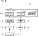
- Fig. 2 is a schematic block diagram showing a software constitution of the water quality management device according to the first embodiment.
- the water quality management device 110 includes an acquisition unit 1101, a water quality index value acquisition unit 1101a, an environmental data acquisition unit 1101b, an operating data acquisition unit 1101c, a relational storage unit 1102, a determining unit 1103, a controller 1104, an input unit 1105, and an updating unit 1106.
- the acquisition unit 1101 acquires plant data on the power generating plant 10.
- the acquisition unit 1101 includes the water quality index value acquisition unit 1101a, the environmental data acquisition unit 1101b, and the operating data acquisition unit 1101c.
- the water quality index value acquisition unit 1101a acquires the water quality index values indicating the water quality as the plant data from the circulating water quality sensor 1052, the makeup water quality sensor 1062, and the drainage water quality sensor 1072.
- the water quality index value acquisition unit 1101a acquires the circulating water quality index value from the circulating water quality sensor 1052.
- the water quality index value acquisition unit 1101a acquires the makeup water quality index value from the makeup water quality sensor 1062.
- the water quality index value acquisition unit 1101a acquires the drainage water quality index value from the drainage water quality sensor 1072.
- the environmental data acquisition unit 1101b acquires the environmental data (the weather, the temperature, the humidity, the water quality of the makeup water, or the like) in the periphery of the power generating plant 10 as the plant data from the environmental measuring device 111.
- the environmental data the weather, the temperature, the humidity, the water quality of the makeup water, or the like
- the operating data acquisition unit 1101c acquires the operating data (the output of the power generating plant 10, the temperature or the pressure of the boiler, or the like) of the power generating plant 10 as the plant data from the operation monitoring device 112.
- the relational storage unit 1102 stores relationships between the circulating water quality index value, the makeup water quality index value, the drainage water quality index value, and environmental data and target values of a concentration rate of the cooling water of the cooling water circulation line 105.
- the concentration rate is a value obtained by dividing an amount of makeup water by an amount of drainage water.
- the relational storage unit 1102 stores one or more inference rules.
- the relational storage unit 1102 stores provisional inference rules determined by an engineer in advance in an initial state.
- Examples of a format of the inference rule include a format "when the circulating water quality index value is X1 or more and X2 or less, the makeup water quality index value is Y1 or more and Y2 or less, and the drainage water quality index value is Z1 or more and Z2 or less, the target value of a concentration rate of cooling water is T.”
- Examples of a variable used for a condition of the inference rule include a water quality index value, a change rate of the water quality index value, a statistic of the water quality index value, operating data, a change rate of the operating data, a statistic of the operating data, environmental data, a change rate of the environmental data, and a statistic of the environmental data.
- the determining unit 1103 determines the target value of the concentration rate of the cooling water of the cooling water circulation line 105 based on the water quality index values acquired by the water quality index value acquisition unit 1101a, the environmental data acquired by the environmental data acquisition unit 1101b, the operating data acquired by the operating data acquisition unit 1101c, and the inference rule stored in the relational storage unit 1102. To be specific, when the relational storage unit 1 102 stores a plurality of inference rules, the determining unit 1103 determines the target value of the concentration rate of the cooling water by obtaining a plurality of inference results based respectively on the inference rules and integrating the inference results. Therefore, the determining unit 1103 can increase accuracy of the target value of the concentration rate.
- the inference rule examples include a neural network, a Bayesian network, a support vector machine, and case-based reasoning.
- the determining unit 1103 may determine the target value by specifying one inference rule among the plurality of inference rules in addition to determining the target value based on the plurality of inference rules.
- the determining unit 1103 is realized by an inference engine.
- the relational storage unit 1102 and the determining unit 1103 function as an expert system which is an example of artificial intelligence.
- the controller 1104 outputs a control instruction to the fourth feed pump 1061, the blowdown valve 1071, and the second chemical injection pump 1082 based on the target value of the concentration rate of the cooling water determined by the determining unit 1103.
- the concentration rate is the value obtained by dividing the amount of makeup water by the amount of drainage water.
- the amount of drainage water is specified by multiplying a ratio of a target value of electrical conductivity of cooling water and an actually measured value thereof by the amount of makeup water. Therefore, the controller 1104 can calculate the amount of makeup water and the amount of drainage water based on a concentration rate of the cooling water.
- an amount of chemical injection is an amount which is proportional to the amount of drainage water. Therefore, the controller 1104 can calculate the amount of chemical injection based on the specified amount of drainage water.
- the input unit 1105 receives an input of a target value of the concentration rate of the cooling water from a skilled engineer.
- the target value is an appropriate target value which is specified by the skilled engineer based on the water quality index values acquired by the water quality index value acquisition unit 1101a, the environmental data acquired by the environmental data acquisition unit 1101b, and the operating data acquired by the operating data acquisition unit 1101c.
- the skilled engineer specifies the target value of the concentration rate of the cooling water such that the drainage water quality index value does not exceed a predetermined drainage water regulation value, that the circulating water system is not deteriorated due to scale, slime, or corrosion, and that water quality management cost is reduced.
- the water quality management cost increases as the amount of makeup water, the amount of drainage water, and the amount of chemical injection increase.
- the input unit 1105 receives an input of a reason for which the target value is determined from the skilled engineer.
- the reason for which the target value is determined include a format "because the circulating water quality index value is X1 or more and the makeup water quality index value is Y1 or more.”
- the input unit 1105 can receive an input of the same format as a condition part of the inference rule as the reason for which the target value is determined.
- the updating unit 1106 generates the inference rule based on the concentration rate and the reason input to the input unit 1105.
- the updating unit 1106 stores the generated inference rule in the relational storage unit 1102.
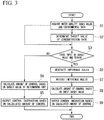
- Fig. 3 is a flowchart illustrating an operation of the water quality management device according to the first embodiment.
- the water quality management device 110 When the water quality management device 110 is started, the water quality management device 110 performs the following process at regular time intervals.
- the water quality index value acquisition unit 1101a acquires the water quality index values indicating the water quality from the circulating water quality sensor 1052, the makeup water quality sensor 1062, and the drainage water quality sensor 1072.
- the environmental data acquisition unit 1101b acquires the environmental data from the environmental measuring device 111.
- the operating data acquisition unit 1101c acquires the environmental data from the operation monitoring device 112.
- the water quality index value acquisition unit 1101a acquires the circulating water quality index value, the makeup water quality index value, and the drainage water quality index value
- the environmental data acquisition unit 1101 b acquires the environmental data
- the operating data acquisition unit 1101c acquires the operating data (Step S1).
- the determining unit 1 103 determines the target value of the concentration rate of the cooling water based on the inference rule stored in the relational storage unit 1102 (Step S2).
- the inference rule is sequentially updated using the determination of the engineer (the input target value) as data for learning, through a process of Step S3 and Step S4 which will be described below. Therefore, the learning of the determining unit 1 1 03 in the water quality management device 110 proceeds, and accuracy of the determined target value of the concentration rate of the cooling water is thus increased.
- Step S3 determines whether the target value of the concentration rate and the reason for which the target value is determined are input to the input unit 1 105 from the skilled engineer (Step S3).
- Step S3: NO the controller 1104 calculates the amount of makeup water, the amount of drainage water, and the amount of chemical injection based on the target value of the concentration rate determined by the determining unit 1 1 03 in Step S2 (Step S4).
- the controller 1104 controls the fourth feed pump 1061, the blowdown valve 1071, and the second chemical injection pump 1082 based on the calculated results (Step S5).
- the controller 1104 outputs a control instruction to the fourth feed pump 1 061 to supply the calculated amount of makeup water.
- the controller 1104 outputs a control instruction to the blowdown valve 1071 to drain the calculated amount of drainage water.
- the controller 1104 outputs a control instruction to the second chemical injection pump 1082 to inject the calculated amount of chemical injection.
- Step S3 when the target value of the concentration rate and the reason for which the target value is determined are input to the input unit 1105 (Step S3: YES), the updating unit 1106 generates the inference rules based on the target value and the reason input to the input unit 1105 (Step S6). Subsequently, the updating unit 1106 stores the generated inference rules in the relational storage unit 1102 (Step S7). As described above, since the inference rules stored by the relational storage unit 1102 are sequentially updated according to the determination of the skilled engineer, the learning of the determining unit 1 103 proceeds, and accuracy of the determined target value of the concentration rate of the cooling water is thus increased.
- the controller 1104 calculates an amount of control of the circulating water system, that is, the amount of makeup water, the amount of drainage water, and the amount of chemical injection based on the target value of the concentration rate of the cooling water input to the input unit 1 105 (Step S8). Subsequently, the controller 1104 controls the fourth feed pump 1061, the blowdown valve 1071, and the second chemical injection pump 1082 based on the calculated results (Step S9). To be specific, the controller 1104 outputs a control instruction to the fourth feed pump 1 061 to supply the calculated amount of makeup water. The controller 1104 outputs a control instruction to the blowdown valve 1071 to drain the calculated amount of drainage water. The controller 1104 outputs a control instruction to the second chemical injection pump 1082 to inject the calculated amount of chemical injection.
- the water quality index value acquisition unit 1101a acquires the water quality index values including the makeup water quality index value indicating the water quality of the makeup water and the circulating water quality index value indicating the water quality of the circulating water.
- the determining unit determines the concentration rate of the cooling water of the circulating water system based on the water quality index values acquired by the water quality index value acquisition unit 1101a.
- the water quality management device 110 can appropriately manage the water quality of the circulating water system even if the water quality of the makeup water is not constant.
- the relational storage unit 1102 stores the inference rule indicating a relationship between the water quality index values and amounts of concentration control.
- the determining unit 1 1 03 determines the concentration rate based on the water quality index values acquired by the water quality index value acquisition unit 1101a and the relationship stored in the relational storage unit 1102.
- the water quality management device 110 can appropriately manage the water treatment system 100 by storing the inference rule for obtaining such a concentration rate that a drainage regulation is satisfied, that the circulating water system is not deteriorated, and that water quality management cost can be suppressed, in the relational storage unit 1102.
- the input unit 1105 receives the input of the concentration rate of the cooling water which satisfies a predetermined limit value and is specified by the engineer (a professional engineer or an expert) based on the water quality index values acquired by the water quality index value acquisition unit 1101a.
- the predetermined limit value include a drainage water regulation value, water quality leading to deterioration of a circulating water system, and water quality management cost.
- the updating unit 1106 updates the relationship stored in the relational storage unit 1102 based on the concentration rate input to the input unit 1105.
- the inference rule for obtaining the concentration rate which satisfies the predetermined limit value is accumulated in the relational storage unit 1102. Therefore, the water quality management device 110 can appropriately manage the water treatment system 100.
- the water quality management device 110 manages the water quality of the circulating water system constituted by the cooling water circulation line 105, the second supply line 106, the second drainage line 107, and the second chemical injection line 108.
- a water quality management device 110 according to a second embodiment manages water quality of a circulating water system constituted by a steam circulation line 101, a first supply line 102, a first drainage line 103, and a first chemical injection line 104.
- Fig. 4 is a schematic block diagram showing a constitution of a water treatment system according to the second embodiment.
- a circulating water quality sensor 1052 is provided in the steam circulation line 101.
- the makeup water quality sensor 1062 is provided in the first supply line 102.
- the drainage water quality sensor 1072 is provided in the first drainage line 103.
- the water quality management device 110 determines power of a second feed pump 1021, an amount of drainage water in a boiler 11, and power of a first chemical injection pump 1042 based on water qualities detected by the circulating water quality sensor 1052, the makeup water quality sensor 1062, and the drainage water quality sensor 1072.
- An operation of the water quality management device 110 according to this embodiment is the same as that of the first embodiment.
- the water quality management device 110 can appropriately manage the water quality of the circulating water system constituted by the steam circulation line 101, the first supply line 102, the first drainage line 103, and the first chemical injection line 104.
- the determining unit 1103 of the water quality management device 110 calculates the concentration rate, but the present invention is not limited thereto.
- a determining unit 11 03 of another embodiment may calculate another amount of concentration control associated with a concentration rate. Examples of the amount of concentration control include a concentration rate, an amount of water supply, an amount of drainage water, an amount of chemical injection, an opening of a valve, and power of a pump.
- the input unit 1105 receives the input of the reason for which the target value is determined in addition to the target value of the concentration rate of the circulating water, but the present invention is not limited thereto.
- An input unit 1105 according to another embodiment may not receive an input of a reason for which the target value is determined.
- an updating unit 1 106 updates an inference rule based on a target value of a concentration rate of circulating water input to an input unit 1105, water quality index values acquired by a water quality index value acquisition unit 1101a, and environmental data acquired by an environmental data acquisition unit 1101b.
- the determining unit 1103 specifies one inference rule from the plurality of inference rules stored by the relational storage unit 1102 and determines the amount of concentration control based on the specified inference rule, but the present invention is not limited thereto.
- the determining unit 1103 according to another embodiment may determine the amount of concentration control based on an artificial intelligence technique other than an expert system.
- the determining unit 1103 according to another embodiment may determine the amount of concentration control using a determination technique based on machine learning.
- a relational storage unit 1102 stores a predictive model acquired by machine learning.
- the predictive model is an example of a relationship between water quality index values and amounts of concentration control.
- the updating unit 1106 updates the predictive model stored by the relational storage unit 1102 using, as teacher data, a combination of the target value of the concentration rate input to the input unit 1105, the water quality index values acquired by the water quality index value acquisition unit 1101a, the environmental data acquired by the environmental data acquisition unit 1101b, and operating data acquired by an operating data acquisition unit 1101c.
- the determining unit 1103 determines the target value of the concentration rate based on the circulating water quality index value, the makeup water quality index value, and the drainage water quality index value, but the present invention is not limited thereto.
- the determining unit 1103 according to another embodiment may determine the target value of the concentration rate without using the drainage water quality index value. This is because the circulating water quality index value and the drainage water quality index value are substantially the same. Also, the determining unit 1103 according to another embodiment may determine the target value of the concentration rate using another water quality index value in addition to the circulating water quality index value and the makeup water quality index value.
- the water quality management device 110 includes the controller 1104 which controls the circulating water system, but the present invention is not limited thereto.
- the water quality management device 110 may output the concentration rate determined by the determining unit 1103 to the outside, and may not control the circulating water system.
- the water quality management device 110 may display the target value of the concentration rate determined by the determining unit 1103 or the amount of control of the circulating water system on an external display device. In this case, an operator controls the circulating water system in accordance with the displayed target value of the concentration rate or amount of control.
- Fig. 5 is a schematic block diagram showing a constitution of a computer according to at least one embodiment.
- a computer 900 includes a central processing unit (CPU) 901, a main storage device 902, an auxiliary storage device 903, and an interface 904.
- CPU central processing unit
- main storage device 902 main storage device
- auxiliary storage device 903 main storage device
- the above-described water quality management device 110 is mounted on the computer 900. Operations of the above-described processing units are stored in the auxiliary storage device 903 in the form of a program.
- the CPU 901 reads the program from the auxiliary storage device 903, develops the program on the main storage device 902, and executes the above-described processes in accordance with the program.
- the CPU 901 forms a storage region corresponding to the above-described relational storage unit 1102 in the main storage device 902 or the auxiliary storage device 903 in accordance with the program.
- the auxiliary storage device 903 is an example of computer-readable media.
- Other examples of the computer-readable media include a magnetic disk, a magneto-optical disc, a compact disc-read only memory (CD-ROM), a digital versatile disc-read only memory (DVD-ROM), a semiconductor memory, and other types of non-transitory tangible media connected through the interface 904.
- the computer 900 which receives the delivered program may develop the program on the main storage device 902 and execute the above-described processes.
- the program may be for the purpose of implementing some of the above-described functions.
- the program may be a so-called differential file (differential program) that implements the above-described functions in combination with other programs which have already been stored in the auxiliary storage device 903.
- At least a portion of the above-described water quality management device 110 may be realized by a semiconductor circuit such as an application specific integrated circuit (ASIC).
- ASIC application specific integrated circuit
- the water quality management device determines an amount of concentration control based on a makeup water quality index value indicating water quality of makeup water in addition to a circulating water quality index value indicating water quality of circulating water circulating through a circulation line.
- the water quality management device can appropriately manage water quality of a circulating water system even if the water quality of the makeup water is not constant.
Landscapes
- Engineering & Computer Science (AREA)
- Water Supply & Treatment (AREA)
- Physics & Mathematics (AREA)
- Chemical & Material Sciences (AREA)
- Thermal Sciences (AREA)
- General Engineering & Computer Science (AREA)
- Mechanical Engineering (AREA)
- Organic Chemistry (AREA)
- Hydrology & Water Resources (AREA)
- Artificial Intelligence (AREA)
- Health & Medical Sciences (AREA)
- Environmental & Geological Engineering (AREA)
- Life Sciences & Earth Sciences (AREA)
- Medicinal Chemistry (AREA)
- General Physics & Mathematics (AREA)
- Automation & Control Theory (AREA)
- Evolutionary Computation (AREA)
- Computer Vision & Pattern Recognition (AREA)
- Software Systems (AREA)
- Medical Informatics (AREA)
- Testing And Monitoring For Control Systems (AREA)
- Preventing Corrosion Or Incrustation Of Metals (AREA)
- Control Of Non-Electrical Variables (AREA)
Abstract
Description
- The present invention relates to a water quality management device, a water treatment system, a water quality management method, and a program for optimizing a water treatment system.
- Cooling water systems which circulate cooling water for cooling steam discharged from a steam turbine are provided in thermal power plants in some cases. The cooling water system includes a condenser which cools steam and a cooling tower which cools cooling water heated in the condenser. There is a need to constantly supply makeup water to the cooling water system because cooling water is evaporated in the atmosphere in the cooling tower. Substances which cause deterioration of the cooling water system can be included in the makeup water. Examples of the substances which cause deterioration include salts which can cause corrosion or be converted into evaporation residues and silica which can cause scale. A certain amount of cooling water is discharged, and a certain amount of chemicals are injected not to deteriorate the cooling water system.
-
Patent Literature 1 discloses a method of blowing (discharging) circulating cooling water and injecting makeup water when electrical conductivity of the cooling water is higher than a set value, and stopping the blowing when the electrical conductivity of the cooling water is lower than the set value, as a method of controlling chemical injection in conjunction with an amount of makeup water. - [Patent Literature 1]
Japanese Examined Patent Application, Second Publication No.S57-3875 - However, when water quality of makeup water is not constant, the method disclosed in
Patent Literature 1 may fail to appropriately manage the water quality of a cooling water system. For example, raw water acquired from groundwater or surface water is known as varying in water quality. For this reason, when raw water is used as makeup water, there is a need to determine a target value of a concentration rate of cooling water using water quality of the makeup water in the worst state as a reference and perform control. There is a plurality of variables which define the water quality of the makeup water. The target value of the concentration rate is changed according to a combination of the plurality of variables. When the target value of the concentration rate of the cooling water is not changed even if the water quality of the raw water is changed, despite an operation at a higher concentration rate being possible, the water quality is managed at a low concentration rate. For this reason, a chemical is injected into the cooling water system more than necessary, and water quality management cost cannot thus be suppressed. - There is also a technical problem in a conventional control system which defines an amount of blowing using electrical conductivity because errors occur in an electrical conductivity meter which has been operated for a long time, and thus it is difficult to ascertain a correct value if calibration is not frequently performed.
- An object of the present invention is to provide a water quality management device, a water treatment system, a water quality management method, and a program for optimizing a water treatment system which appropriately manage water quality of a circulating water system even if water quality of makeup water is not constant.
- According to a first aspect of the present invention, a water quality management device is a water quality management device which manages a circulating water system of a plant including a circulation line through which circulating water is circulated, a supply line which supplies makeup water to the circulation line, a discharge line which discharges the circulating water from the circulation line, and a chemical injection line which injects a chemical to the circulation line, the water quality management device including: a determining unit configured to determine an amount of concentration control associated with a concentration rate of the circulating water system; an acquisition unit configured to acquire plant data on the plant used by the determining unit to determine the amount of concentration control; a relational storage unit configured to store an inference rule associating a condition of the plant data and an amount of concentration control of when the condition is satisfied with each other; an input unit configured to receive an input of an amount of concentration control which satisfies a predetermined limit value and is specified based on the plant data acquired by the acquisition unit; and an updating unit configured to generate a new inference rule based on the amount of concentration control input to the input unit and record the new inference rule on the relational storage unit, wherein the determining unit determines an amount of concentration control based on the plant data acquired by the acquisition unit and the inference rule stored in the relational storage unit.
- According to a second aspect of the present invention, the water quality management device according to the first aspect may further include a relational storage unit configured to store a relationship between the plant data and the amount of concentration control, wherein the determining unit may determine an amount of concentration control based on the plant data acquired by the acquisition unit and the relationship stored by the relational storage unit.
- According to a third aspect of the present invention, the water quality management device according to the first or second aspect may further include a controller configured to control at least one of the amount of makeup water supplied to the supply line, the amount of circulating water discharged from the discharge line, and the amount of chemical injected to the circulation line based on the amount of concentration control determined by the determining unit.
- According to a fourth aspect of the present invention, in the water quality management device according to the first aspect, the acquisition unit may include a water quality index value acquisition unit which acquires water quality index values including a makeup water quality index value indicating water quality of the makeup water and a circulating water quality index value indicating water quality of the circulating water, and the determining unit may determine the amount of concentration control based on the water quality index values acquired by the water quality index value acquisition unit.
- According to a fifth aspect of the present invention, in the water quality management device according to the fourth aspect, the water quality index values may include a discharge water quality index value indicating water quality of the circulating water discharged from the discharge line.
- According to a sixth aspect of the present invention, in the water quality management device according to the first aspect, the acquisition unit may include an environmental data acquisition unit which acquires environmental data of a plant, and the determining unit may determine the amount of concentration control based on the environmental data acquired by the environmental data acquisition unit.
- According to a seventh aspect of the present invention, in the water quality management device according to the first aspect, the acquisition unit may include an operating data acquisition unit which acquires operating data of a plant, and the determining unit may determine the amount of concentration control based on the operating data acquired by the operating data acquisition unit.
- According to an eighth aspect of the present invention, a water treatment system includes: a circulating water system including a circulation line through which circulating water is circulated, a supply line which supplies makeup water to the circulation line, a discharge line which discharges the circulating water from the circulation line, and a chemical injection line which injects a chemical to the circulation line; and the water quality management device according to any one of the first to seventh aspects.
- According to a ninth aspect of the present invention, a water quality management method is a water quality management method of a circulating water system of a plant including a circulation line through which circulating water is circulated, a supply line which supplies makeup water to the circulation line, a discharge line which discharges the circulating water from the circulation line, and a chemical injection line which injects a chemical to the circulation line, the water quality management method including: an acquisition step of acquiring plant data on the plant; an input step of receiving an input of an amount of concentration control which satisfies a predetermined limit value and is specified based on the acquired plant data; an updating step of generating a new inference rule based on the input amount of concentration control and storing the new inference rule in a relational storage unit which stores an inference rule associating a condition of the plant data and an amount of concentration control of when the condition is satisfied with each other; and a determination step of determining an amount of concentration control based on the plant data acquired in the acquisition step and the inference rule stored by the relational storage unit.
- According to a tenth aspect of the present invention, a program for optimizing a water treatment system causes a computer of a water quality management device which manages a circulating water system of a plant including a circulation line through which circulating water is circulated, a supply line which supplies makeup water to the circulation line, a discharge line which discharges the circulating water from the circulation line, and a chemical injection line which injects a chemical to the circulation line, to function as: an acquisition unit configured to acquire plant data on the plant; a determining unit configured to determine an amount of concentration control based on the plant data acquired by the acquisition unit; a relational storage unit configured to store an inference rule associating a condition of the plant data and an amount of concentration control of when the condition is satisfied with each other; an input unit configured to receive an input of an amount of concentration control which satisfies a predetermined limit value and is specified based on the plant data acquired by the acquisition unit; and an updating unit configured to generate a new inference rule based on the amount of concentration control input to the input unit and record the new inference rule on the relational storage unit, wherein the determining unit determines an amount of concentration control based on the plant data acquired by the acquisition unit and the inference rule stored by the relational storage unit.
- According to at least one aspect of the above-described aspects, the water quality management device determines an amount of concentration control based on a makeup water quality index value indicating water quality of makeup water in addition to a circulating water quality index value indicating water quality of circulating water circulating through a circulation line. Thus, the water quality management device can appropriately manage water quality of a circulating water system even if the water quality of the makeup water is not constant.
-
-
Fig. 1 is a schematic block diagram showing a constitution of a water treatment system according to a first embodiment. -
Fig. 2 is a schematic block diagram showing a software constitution of the water quality management device according to the first embodiment. -
Fig. 3 is a flowchart illustrating an operation of the water quality management device according to the first embodiment. -
Fig. 4 is a schematic block diagram showing a constitution of a water treatment system according to a second embodiment. -
Fig. 5 is a schematic block diagram showing a constitution of a computer according to at least one embodiment. - Hereinafter, embodiments will be described in detail with reference to the accompanying drawings.
-
Fig. 1 is a schematic block diagram showing a constitution of a water treatment system according to a first embodiment. - A
water treatment system 100 according to this embodiment is provided for apower generating plant 10. Thepower generating plant 10 includes aboiler 11, asteam turbine 12, anelectric generator 13, acondenser 14, awater purification device 15, and acooling tower 16. - The
boiler 11 generates steam by evaporating water. Thesteam turbine 12 is rotated using the steam generated by theboiler 11. Theelectric generator 13 converts rotational energy of thesteam turbine 12 into electric power. Thecondenser 14 heat-exchanges steam discharged from thesteam turbine 12 with cooling water to convert the steam into water. Thewater purification device 15 generates pure water. Thecooling tower 16 cools the cooling water heat-exchanged by thecondenser 14. Thecooling tower 16 is provided with fans (not shown) configured to cool the cooling water. The fans are configured such that rotational speeds thereof can be controlled by inverter control or by controlling the number of fans to be operated. - The
water treatment system 100 includes asteam circulation line 101, afirst supply line 102, afirst drainage line 103, a firstchemical injection line 104, a coolingwater circulation line 105, asecond supply line 106, asecond drainage line 107, a secondchemical injection line 1 08, a drainagewater treatment device 109, a waterquality management device 110, and anenvironmental measuring device 111. - The
steam circulation line 101 is a line through which water and steam are circulated to thesteam turbine 12, thecondenser 14, and theboiler 11. Afirst feed pump 1011 is provided between thecondenser 14 and theboiler 11 in thesteam circulation line 101. Thefirst feed pump 1011 pumps the water from thecondenser 14 toward theboiler 11. - The
first supply line 102 is a line which supplies the pure water generated by thewater purification device 15 to thesteam circulation line 101. Thefirst supply line 102 is provided with asecond feed pump 1021. Thesecond feed pump 1021 is used when thecondenser 14 is filled with water. Water within thefirst supply line 102 is pumped from thewater purification device 15 toward thecondenser 14 due to decompression of thecondenser 14 during operation. - The
first drainage line 103 is a line which discharges a portion of water circulating through thesteam circulation line 101 from theboiler 11 to the drainagewater treatment device 109. - The first
chemical injection line 104 is a line which supplies a pH adjusting agent, a deoxidizer, or another chemical to thesteam circulation line 101. The firstchemical injection line 104 includes a firstchemical injection tank 1041 which stores a chemical and a firstchemical injection pump 1042 which supplies the chemical from the firstchemical injection tank 1041 to thesteam circulation line 101. - A circulating water system is constituted by the
steam circulation line 101, thefirst supply line 102, thefirst drainage line 103, and the firstchemical injection line 104. - The cooling
water circulation line 105 is a line through which cooling water is circulated to thecondenser 14 and thecooling tower 16. The coolingwater circulation line 105 is provided with athird feed pump 1051 and a circulatingwater quality sensor 1052. Thethird feed pump 1051 pumps the cooling water from thecooling tower 16 toward thecondenser 14. The circulatingwater quality sensor 1052 detects water quality of the cooling water circulating through the coolingwater circulation line 105. Examples of the water quality detected by the sensor include electrical conductivity, a pH value, a concentration of a salt, a concentration of a metal, chemical oxygen demand (COD), biochemical oxygen demand (BOD), a concentration of silica, and a combination thereof. The circulatingwater quality sensor 1052 outputs a circulating water quality index value indicating the detected water quality to the waterquality management device 110. - The
second supply line 106 is a line which supplies raw water acquired from a water source as makeup water to the coolingwater circulation line 105. Thesecond supply line 106 is provided with afourth feed pump 1061 and a makeupwater quality sensor 1062. Thefourth feed pump 1061 pumps the makeup water from the water source toward thecooling tower 16. The makeupwater quality sensor 1062 outputs a makeup water quality index value indicating detected water quality to the waterquality management device 110. - The
second drainage line 107 is a line which discharges a portion of water circulating through the coolingwater circulation line 105 to the drainagewater treatment device 109. Thesecond drainage line 107 is provided with ablowdown valve 1071 and a drainagewater quality sensor 1072. Theblowdown valve 1071 limits an amount of drainage water which is blown from the coolingwater circulation line 105 to the drainagewater treatment device 109. The drainagewater quality sensor 1072 detects the water quality of drainage water discharged from thesecond drainage line 107. The drainagewater quality sensor 1072 outputs a drainage water quality index value indicating the detected water quality to the waterquality management device 110. - The second
chemical injection line 108 is a line which supplies a corrosion inhibitor, a scale inhibitor, a slime control agent, a pH adjusting agent, or another chemical to the coolingwater circulation line 105. The secondchemical injection line 108 includes a secondchemical injection tank 1081 which stores a chemical and a secondchemical injection pump 1082 which supplies the chemical from the secondchemical injection tank 1081 to the coolingwater circulation line 105. - The circulating water system is constituted by the cooling
water circulation line 105, thesecond supply line 106, thesecond drainage line 107, and the secondchemical injection line 108. - The drainage
water treatment device 109 injects an acid, an alkali, a flocculant, or another chemical into drainage water discharged from thefirst drainage line 1 03 and thesecond drainage line 107. The drainagewater treatment device 109 discards drainage water treated by a chemical. - The water
quality management device 110 determines power of thefourth feed pump 1061, an opening degree of theblowdown valve 1071, and an amount of injection of the second chemical injection pump 1082 (an amount of stroke or the number of strokes of a plunger) based on the water quality detected by the circulatingwater quality sensor 1052, the water quality detected by the makeupwater quality sensor 1062, the water quality detected by the drainagewater quality sensor 1072, and environmental data in the periphery of thepower generating plant 10 measured by theenvironmental measuring device 111. - The
environmental measuring device 111 measures the environment in the periphery of thepower generating plant 10 and generates the environmental data. Examples of environmental data include weather, a temperature, a humidity, and water quality (a turbidity level or the like) of makeup water in a surrounding region of thepower generating plant 10. - An
operation monitoring device 112 measures operating data of thepower generating plant 10 and generates the operating data. Examples of the operating data include an output of thepower generating plant 10, various flow rates (of steam, water, cooling water, a chemical, and the like), a temperature or a pressure of a boiler, a temperature of cooling water, an air volume of a cooling tower, and the like. -
Fig. 2 is a schematic block diagram showing a software constitution of the water quality management device according to the first embodiment. - The water
quality management device 110 includes anacquisition unit 1101, a water quality indexvalue acquisition unit 1101a, an environmentaldata acquisition unit 1101b, an operatingdata acquisition unit 1101c, arelational storage unit 1102, a determiningunit 1103, acontroller 1104, aninput unit 1105, and anupdating unit 1106. - The
acquisition unit 1101 acquires plant data on thepower generating plant 10. To be specific, theacquisition unit 1101 includes the water quality indexvalue acquisition unit 1101a, the environmentaldata acquisition unit 1101b, and the operatingdata acquisition unit 1101c. - The water quality index
value acquisition unit 1101a acquires the water quality index values indicating the water quality as the plant data from the circulatingwater quality sensor 1052, the makeupwater quality sensor 1062, and the drainagewater quality sensor 1072. The water quality indexvalue acquisition unit 1101a acquires the circulating water quality index value from the circulatingwater quality sensor 1052. The water quality indexvalue acquisition unit 1101a acquires the makeup water quality index value from the makeupwater quality sensor 1062. The water quality indexvalue acquisition unit 1101a acquires the drainage water quality index value from the drainagewater quality sensor 1072. - The environmental
data acquisition unit 1101b acquires the environmental data (the weather, the temperature, the humidity, the water quality of the makeup water, or the like) in the periphery of thepower generating plant 10 as the plant data from theenvironmental measuring device 111. - The operating
data acquisition unit 1101c acquires the operating data (the output of thepower generating plant 10, the temperature or the pressure of the boiler, or the like) of thepower generating plant 10 as the plant data from theoperation monitoring device 112. - The
relational storage unit 1102 stores relationships between the circulating water quality index value, the makeup water quality index value, the drainage water quality index value, and environmental data and target values of a concentration rate of the cooling water of the coolingwater circulation line 105. The concentration rate is a value obtained by dividing an amount of makeup water by an amount of drainage water. Therelational storage unit 1102 stores one or more inference rules. Therelational storage unit 1102 stores provisional inference rules determined by an engineer in advance in an initial state. Examples of a format of the inference rule include a format "when the circulating water quality index value is X1 or more and X2 or less, the makeup water quality index value is Y1 or more and Y2 or less, and the drainage water quality index value is Z1 or more and Z2 or less, the target value of a concentration rate of cooling water is T." Examples of a variable used for a condition of the inference rule include a water quality index value, a change rate of the water quality index value, a statistic of the water quality index value, operating data, a change rate of the operating data, a statistic of the operating data, environmental data, a change rate of the environmental data, and a statistic of the environmental data. - The determining
unit 1103 determines the target value of the concentration rate of the cooling water of the coolingwater circulation line 105 based on the water quality index values acquired by the water quality indexvalue acquisition unit 1101a, the environmental data acquired by the environmentaldata acquisition unit 1101b, the operating data acquired by the operatingdata acquisition unit 1101c, and the inference rule stored in therelational storage unit 1102. To be specific, when therelational storage unit 1 102 stores a plurality of inference rules, the determiningunit 1103 determines the target value of the concentration rate of the cooling water by obtaining a plurality of inference results based respectively on the inference rules and integrating the inference results. Therefore, the determiningunit 1103 can increase accuracy of the target value of the concentration rate. Examples of the inference rule include a neural network, a Bayesian network, a support vector machine, and case-based reasoning. The determiningunit 1103 may determine the target value by specifying one inference rule among the plurality of inference rules in addition to determining the target value based on the plurality of inference rules. The determiningunit 1103 is realized by an inference engine. In other words, therelational storage unit 1102 and the determiningunit 1103 function as an expert system which is an example of artificial intelligence. - The
controller 1104 outputs a control instruction to thefourth feed pump 1061, theblowdown valve 1071, and the secondchemical injection pump 1082 based on the target value of the concentration rate of the cooling water determined by the determiningunit 1103. The concentration rate is the value obtained by dividing the amount of makeup water by the amount of drainage water. The amount of drainage water is specified by multiplying a ratio of a target value of electrical conductivity of cooling water and an actually measured value thereof by the amount of makeup water. Therefore, thecontroller 1104 can calculate the amount of makeup water and the amount of drainage water based on a concentration rate of the cooling water. Also, an amount of chemical injection is an amount which is proportional to the amount of drainage water. Therefore, thecontroller 1104 can calculate the amount of chemical injection based on the specified amount of drainage water. - The
input unit 1105 receives an input of a target value of the concentration rate of the cooling water from a skilled engineer. The target value is an appropriate target value which is specified by the skilled engineer based on the water quality index values acquired by the water quality indexvalue acquisition unit 1101a, the environmental data acquired by the environmentaldata acquisition unit 1101b, and the operating data acquired by the operatingdata acquisition unit 1101c. The skilled engineer specifies the target value of the concentration rate of the cooling water such that the drainage water quality index value does not exceed a predetermined drainage water regulation value, that the circulating water system is not deteriorated due to scale, slime, or corrosion, and that water quality management cost is reduced. The water quality management cost increases as the amount of makeup water, the amount of drainage water, and the amount of chemical injection increase. In this case, theinput unit 1105 receives an input of a reason for which the target value is determined from the skilled engineer. Examples of the reason for which the target value is determined include a format "because the circulating water quality index value is X1 or more and the makeup water quality index value is Y1 or more." In other words, theinput unit 1105 can receive an input of the same format as a condition part of the inference rule as the reason for which the target value is determined. - The
updating unit 1106 generates the inference rule based on the concentration rate and the reason input to theinput unit 1105. Theupdating unit 1106 stores the generated inference rule in therelational storage unit 1102. - Next, an operation of the water
quality management device 110 according to this embodiment will be described. -
Fig. 3 is a flowchart illustrating an operation of the water quality management device according to the first embodiment. - When the water
quality management device 110 is started, the waterquality management device 110 performs the following process at regular time intervals. - The water quality index
value acquisition unit 1101a acquires the water quality index values indicating the water quality from the circulatingwater quality sensor 1052, the makeupwater quality sensor 1062, and the drainagewater quality sensor 1072. The environmentaldata acquisition unit 1101b acquires the environmental data from theenvironmental measuring device 111. Similarly, the operatingdata acquisition unit 1101c acquires the environmental data from theoperation monitoring device 112. In other words, the water quality indexvalue acquisition unit 1101a acquires the circulating water quality index value, the makeup water quality index value, and the drainage water quality index value, the environmentaldata acquisition unit 1101 b acquires the environmental data, and the operatingdata acquisition unit 1101c acquires the operating data (Step S1). - Subsequently, the determining
unit 1 103 determines the target value of the concentration rate of the cooling water based on the inference rule stored in the relational storage unit 1102 (Step S2). Here, when the target value determined by the determiningunit 1103 is different from the determination of the skilled engineer (the target value input by the skilled engineer), the inference rule is sequentially updated using the determination of the engineer (the input target value) as data for learning, through a process of Step S3 and Step S4 which will be described below. Therefore, the learning of the determiningunit 1 1 03 in the waterquality management device 110 proceeds, and accuracy of the determined target value of the concentration rate of the cooling water is thus increased. - When the determining
unit 1 1 03 determines the target value of the concentration rate in Step S2, the updatingunit 1 1 06 determines whether the target value of the concentration rate and the reason for which the target value is determined are input to theinput unit 1 105 from the skilled engineer (Step S3). When the target value of the concentration rate and the reason for which the target value is determined are not input to the input unit 1105 (Step S3: NO), thecontroller 1104 calculates the amount of makeup water, the amount of drainage water, and the amount of chemical injection based on the target value of the concentration rate determined by the determiningunit 1 1 03 in Step S2 (Step S4). Subsequently, thecontroller 1104 controls thefourth feed pump 1061, theblowdown valve 1071, and the secondchemical injection pump 1082 based on the calculated results (Step S5). To be specific, thecontroller 1104 outputs a control instruction to thefourth feed pump 1 061 to supply the calculated amount of makeup water. Thecontroller 1104 outputs a control instruction to theblowdown valve 1071 to drain the calculated amount of drainage water. Thecontroller 1104 outputs a control instruction to the secondchemical injection pump 1082 to inject the calculated amount of chemical injection. - On the other hand, when the target value of the concentration rate and the reason for which the target value is determined are input to the input unit 1105 (Step S3: YES), the
updating unit 1106 generates the inference rules based on the target value and the reason input to the input unit 1105 (Step S6). Subsequently, theupdating unit 1106 stores the generated inference rules in the relational storage unit 1102 (Step S7). As described above, since the inference rules stored by therelational storage unit 1102 are sequentially updated according to the determination of the skilled engineer, the learning of the determiningunit 1 103 proceeds, and accuracy of the determined target value of the concentration rate of the cooling water is thus increased. Thecontroller 1104 calculates an amount of control of the circulating water system, that is, the amount of makeup water, the amount of drainage water, and the amount of chemical injection based on the target value of the concentration rate of the cooling water input to theinput unit 1 105 (Step S8). Subsequently, thecontroller 1104 controls thefourth feed pump 1061, theblowdown valve 1071, and the secondchemical injection pump 1082 based on the calculated results (Step S9). To be specific, thecontroller 1104 outputs a control instruction to thefourth feed pump 1 061 to supply the calculated amount of makeup water. Thecontroller 1104 outputs a control instruction to theblowdown valve 1071 to drain the calculated amount of drainage water. Thecontroller 1104 outputs a control instruction to the secondchemical injection pump 1082 to inject the calculated amount of chemical injection. - As described above, according to this embodiment, the water quality index
value acquisition unit 1101a acquires the water quality index values including the makeup water quality index value indicating the water quality of the makeup water and the circulating water quality index value indicating the water quality of the circulating water. The determining unit determines the concentration rate of the cooling water of the circulating water system based on the water quality index values acquired by the water quality indexvalue acquisition unit 1101a. Thus, the waterquality management device 110 can appropriately manage the water quality of the circulating water system even if the water quality of the makeup water is not constant. - According to this embodiment, the
relational storage unit 1102 stores the inference rule indicating a relationship between the water quality index values and amounts of concentration control. The determiningunit 1 1 03 determines the concentration rate based on the water quality index values acquired by the water quality indexvalue acquisition unit 1101a and the relationship stored in therelational storage unit 1102. As described above, the waterquality management device 110 can appropriately manage thewater treatment system 100 by storing the inference rule for obtaining such a concentration rate that a drainage regulation is satisfied, that the circulating water system is not deteriorated, and that water quality management cost can be suppressed, in therelational storage unit 1102. - According to this embodiment, the
input unit 1105 receives the input of the concentration rate of the cooling water which satisfies a predetermined limit value and is specified by the engineer (a professional engineer or an expert) based on the water quality index values acquired by the water quality indexvalue acquisition unit 1101a. Examples of the predetermined limit value include a drainage water regulation value, water quality leading to deterioration of a circulating water system, and water quality management cost. Theupdating unit 1106 updates the relationship stored in therelational storage unit 1102 based on the concentration rate input to theinput unit 1105. Thus, the inference rule for obtaining the concentration rate which satisfies the predetermined limit value is accumulated in therelational storage unit 1102. Therefore, the waterquality management device 110 can appropriately manage thewater treatment system 100. - The water
quality management device 110 according to the first embodiment manages the water quality of the circulating water system constituted by the coolingwater circulation line 105, thesecond supply line 106, thesecond drainage line 107, and the secondchemical injection line 108. On the other hand, a waterquality management device 110 according to a second embodiment manages water quality of a circulating water system constituted by asteam circulation line 101, afirst supply line 102, afirst drainage line 103, and a firstchemical injection line 104. -
Fig. 4 is a schematic block diagram showing a constitution of a water treatment system according to the second embodiment. - In a
water treatment system 100 according to this embodiment, installation positions of a circulatingwater quality sensor 1052, a makeupwater quality sensor 1062, and a drainagewater quality sensor 1072 are different from those of the first embodiment. The circulatingwater quality sensor 1052 is provided in thesteam circulation line 101. The makeupwater quality sensor 1062 is provided in thefirst supply line 102. The drainagewater quality sensor 1072 is provided in thefirst drainage line 103. The waterquality management device 110 according to this embodiment determines power of asecond feed pump 1021, an amount of drainage water in aboiler 11, and power of a firstchemical injection pump 1042 based on water qualities detected by the circulatingwater quality sensor 1052, the makeupwater quality sensor 1062, and the drainagewater quality sensor 1072. An operation of the waterquality management device 110 according to this embodiment is the same as that of the first embodiment. - Thus, the water
quality management device 110 can appropriately manage the water quality of the circulating water system constituted by thesteam circulation line 101, thefirst supply line 102, thefirst drainage line 103, and the firstchemical injection line 104. - Although the embodiments have been described in detail above with reference to the accompanying drawings, the specific constitutions are not limited to the above-described constitutions, and various changes in design, etc. are also possible.
- For example, the determining
unit 1103 of the waterquality management device 110 according to the above-described embodiments calculates the concentration rate, but the present invention is not limited thereto. A determiningunit 11 03 of another embodiment may calculate another amount of concentration control associated with a concentration rate. Examples of the amount of concentration control include a concentration rate, an amount of water supply, an amount of drainage water, an amount of chemical injection, an opening of a valve, and power of a pump. - The
input unit 1105 according to the above-described embodiment receives the input of the reason for which the target value is determined in addition to the target value of the concentration rate of the circulating water, but the present invention is not limited thereto. Aninput unit 1105 according to another embodiment may not receive an input of a reason for which the target value is determined. In this case, an updatingunit 1 106 updates an inference rule based on a target value of a concentration rate of circulating water input to aninput unit 1105, water quality index values acquired by a water quality indexvalue acquisition unit 1101a, and environmental data acquired by an environmentaldata acquisition unit 1101b. - The determining
unit 1103 according to the above-described embodiment specifies one inference rule from the plurality of inference rules stored by therelational storage unit 1102 and determines the amount of concentration control based on the specified inference rule, but the present invention is not limited thereto. The determiningunit 1103 according to another embodiment may determine the amount of concentration control based on an artificial intelligence technique other than an expert system. For example, the determiningunit 1103 according to another embodiment may determine the amount of concentration control using a determination technique based on machine learning. In this case, arelational storage unit 1102 stores a predictive model acquired by machine learning. The predictive model is an example of a relationship between water quality index values and amounts of concentration control. Theupdating unit 1106 updates the predictive model stored by therelational storage unit 1102 using, as teacher data, a combination of the target value of the concentration rate input to theinput unit 1105, the water quality index values acquired by the water quality indexvalue acquisition unit 1101a, the environmental data acquired by the environmentaldata acquisition unit 1101b, and operating data acquired by an operatingdata acquisition unit 1101c. - The determining
unit 1103 according to the above-described embodiment determines the target value of the concentration rate based on the circulating water quality index value, the makeup water quality index value, and the drainage water quality index value, but the present invention is not limited thereto. The determiningunit 1103 according to another embodiment may determine the target value of the concentration rate without using the drainage water quality index value. This is because the circulating water quality index value and the drainage water quality index value are substantially the same. Also, the determiningunit 1103 according to another embodiment may determine the target value of the concentration rate using another water quality index value in addition to the circulating water quality index value and the makeup water quality index value. - The water
quality management device 110 according to the above-described embodiment includes thecontroller 1104 which controls the circulating water system, but the present invention is not limited thereto. For example, the waterquality management device 110 according to one embodiment may output the concentration rate determined by the determiningunit 1103 to the outside, and may not control the circulating water system. For example, the waterquality management device 110 may display the target value of the concentration rate determined by the determiningunit 1103 or the amount of control of the circulating water system on an external display device. In this case, an operator controls the circulating water system in accordance with the displayed target value of the concentration rate or amount of control. -
Fig. 5 is a schematic block diagram showing a constitution of a computer according to at least one embodiment. - A
computer 900 includes a central processing unit (CPU) 901, amain storage device 902, anauxiliary storage device 903, and aninterface 904. - The above-described water
quality management device 110 is mounted on thecomputer 900. Operations of the above-described processing units are stored in theauxiliary storage device 903 in the form of a program. TheCPU 901 reads the program from theauxiliary storage device 903, develops the program on themain storage device 902, and executes the above-described processes in accordance with the program. TheCPU 901 forms a storage region corresponding to the above-describedrelational storage unit 1102 in themain storage device 902 or theauxiliary storage device 903 in accordance with the program. - In at least one embodiment, the
auxiliary storage device 903 is an example of computer-readable media. Other examples of the computer-readable media include a magnetic disk, a magneto-optical disc, a compact disc-read only memory (CD-ROM), a digital versatile disc-read only memory (DVD-ROM), a semiconductor memory, and other types of non-transitory tangible media connected through theinterface 904. When the program is delivered to thecomputer 900 through communication lines, thecomputer 900 which receives the delivered program may develop the program on themain storage device 902 and execute the above-described processes. - The program may be for the purpose of implementing some of the above-described functions. The program may be a so-called differential file (differential program) that implements the above-described functions in combination with other programs which have already been stored in the
auxiliary storage device 903. - At least a portion of the above-described water
quality management device 110 may be realized by a semiconductor circuit such as an application specific integrated circuit (ASIC). - The water quality management device determines an amount of concentration control based on a makeup water quality index value indicating water quality of makeup water in addition to a circulating water quality index value indicating water quality of circulating water circulating through a circulation line. Thus, the water quality management device can appropriately manage water quality of a circulating water system even if the water quality of the makeup water is not constant.
-
- 100
- Water treatment system
- 1011
- First feed pump
- 1021
- Second feed pump
- 1051
- Third feed pump
- 1061
- Fourth feed pump
- 1042
- First chemical injection pump
- 1082
- Second chemical injection pump
- 1071
- Blowdown valve
- 1052
- Circulating water quality sensor
- 1062
- Makeup water quality sensor
- 1072
- Drainage water quality sensor
- 110
- Water quality management device
- 1101
- Acquisition unit
- 1101a
- Water quality index value acquisition unit
- 1101b
- Environmental data acquisition unit
- 1101c
- Operating data acquisition unit
- 1102
- Relational storage unit
- 1103
- Determining unit
- 1104
- Controller
- 1105
- Input unit
- 1106
- Updating unit
- 111
- Environmental measuring device
- 112
- Operation monitoring device
Claims (10)
- A water quality management device which manages a circulating water system of a plant including a circulation line through which circulating water is circulated, a supply line which supplies makeup water to the circulation line, a discharge line which discharges the circulating water from the circulation line, and a chemical injection line which injects a chemical to the circulation line, the water quality management device comprising:a determining unit configured to determine an amount of concentration control associated with a concentration rate of the circulating water system;an acquisition unit configured to acquire plant data on the plant used by the determining unit to determine the amount of concentration control;a relational storage unit configured to store one or more inference rules associating a condition of the plant data and an amount of concentration control of when the condition is satisfied with each other;an input unit configured to receive an input of an amount of concentration control which satisfies a predetermined limit value and is specified based on the plant data acquired by the acquisition unit; andan updating unit configured to generate a new inference rule based on the amount of concentration control input to the input unit and record the new inference rule on the relational storage unit,wherein the determining unit determines an amount of concentration control based on the plant data acquired by the acquisition unit and the inference rule stored in the relational storage unit.
- The water quality management device according to claim 1, further comprising a relational storage unit configured to store a relationship between the plant data and the amount of concentration control, wherein the determining unit determines an amount of concentration control based on the plant data acquired by the acquisition unit and the relationship stored by the relational storage unit.
- The water quality management device according to claim 1 or 2, further comprising a controller configured to control at least one of the amount of makeup water supplied to the supply line, the amount of circulating water discharged from the discharge line, and the amount of chemical injected to the circulation line based on the amount of concentration control determined by the determining unit.
- The water quality management device according to claim 1, wherein
the acquisition unit includes a water quality index value acquisition unit which acquires water quality index values including a makeup water quality index value indicating water quality of the makeup water and a circulating water quality index value indicating water quality of the circulating water, and
the determining unit determines the amount of concentration control based on the water quality index values acquired by the water quality index value acquisition unit. - The water quality management device according to claim 4, wherein the water quality index values include a discharge water quality index value indicating water quality of the circulating water discharged from the discharge line.
- The water quality management device according to claim 1, wherein
the acquisition unit includes an environmental data acquisition unit which acquires environmental data of a plant, and
the determining unit determines the amount of concentration control based on the environmental data acquired by the environmental data acquisition unit. - The water quality management device according to claim 1, wherein
the acquisition unit includes an operating data acquisition unit which acquires operating data of a plant, and
the determining unit determines the amount of concentration control based on the operating data acquired by the operating data acquisition unit. - A water treatment system comprising:a circulating water system including a circulation line through which circulating water is circulated, a supply line which supplies makeup water to the circulation line, a discharge line which discharges the circulating water from the circulation line, and a chemical injection line which injects a chemical to the circulation line; andthe water quality management device according to any one of claims 1 to 7.
- A water quality management method of a circulating water system of a plant including a circulation line through which circulating water is circulated, a supply line which supplies makeup water to the circulation line, a discharge line which discharges the circulating water from the circulation line, and a chemical injection line which injects a chemical to the circulation line, the water quality management method comprising:an acquisition step of acquiring plant data on the plant;an input step of receiving an input of an amount of concentration control which satisfies a predetermined limit value and is specified based on the acquired plant data;an updating step of generating a new inference rule based on the input amount of concentration control and storing the new inference rule in a relational storage unit which stores one or more inference rules associating a condition of the plant data and an amount of concentration control of when the condition is satisfied with each other; anda determination step of determining an amount of concentration control based on the plant data acquired in the acquisition step and the inference rule stored by the relational storage unit.
- A program for optimizing a water treatment system which causes a computer of a water quality management device which manages a circulating water system of a plant including a circulation line through which circulating water is circulated, a supply line which supplies makeup water to the circulation line, a discharge line which discharges the circulating water from the circulation line, and a chemical injection line which injects a chemical to the circulation line, to function as:an acquisition unit configured to acquire plant data on the plant;a determining unit configured to determine an amount of concentration control based on the plant data acquired by the acquisition unit;a relational storage unit configured to store one or more inference rules associating a condition of the plant data and an amount of concentration control of when the condition is satisfied with each other;an input unit configured to receive an input of an amount of concentration control which satisfies a predetermined limit value and is specified based on the plant data acquired by the acquisition unit; andan updating unit configured to generate a new inference rule based on the amount of concentration control input to the input unit and record the new inference rule on the relational storage unit,wherein the determining unit determines an amount of concentration control based on the plant data acquired by the acquisition unit and the inference rule stored by the relational storage unit.
Applications Claiming Priority (2)
| Application Number | Priority Date | Filing Date | Title |
|---|---|---|---|
| JP2015184964A JP5925371B1 (en) | 2015-09-18 | 2015-09-18 | Water quality management device, water treatment system, water quality management method, and water treatment system optimization program |
| PCT/JP2016/068994 WO2017047193A1 (en) | 2015-09-18 | 2016-06-27 | Water quality management device, water treatment system, water quality management method, and water treatment system optimization program |
Publications (3)
| Publication Number | Publication Date |
|---|---|
| EP3336425A1 true EP3336425A1 (en) | 2018-06-20 |
| EP3336425A4 EP3336425A4 (en) | 2018-06-27 |
| EP3336425B1 EP3336425B1 (en) | 2022-09-21 |
Family
ID=56069579
Family Applications (1)
| Application Number | Title | Priority Date | Filing Date |
|---|---|---|---|
| EP16846066.5A Active EP3336425B1 (en) | 2015-09-18 | 2016-06-27 | Water quality management device, water treatment system, water quality management method, and water treatment system optimization program |
Country Status (6)
| Country | Link |
|---|---|
| US (1) | US10640392B2 (en) |
| EP (1) | EP3336425B1 (en) |
| JP (1) | JP5925371B1 (en) |
| CN (1) | CN108027137B (en) |
| TW (1) | TWI608211B (en) |
| WO (1) | WO2017047193A1 (en) |
Cited By (1)
| Publication number | Priority date | Publication date | Assignee | Title |
|---|---|---|---|---|
| EP4097648A4 (en) * | 2020-01-29 | 2024-02-28 | Xylem Vue Inc. | SYSTEMS AND METHODS FOR THE EFFECTIVE MANAGEMENT OF FLUID INFRASTRUCTURES |
Families Citing this family (25)
| Publication number | Priority date | Publication date | Assignee | Title |
|---|---|---|---|---|
| JP5925371B1 (en) * | 2015-09-18 | 2016-05-25 | 三菱日立パワーシステムズ株式会社 | Water quality management device, water treatment system, water quality management method, and water treatment system optimization program |
| JP6763630B2 (en) * | 2016-12-27 | 2020-09-30 | 三菱パワー株式会社 | Water quality management system for plants and circulating water systems and water quality management methods for circulating water systems |
| CN111108220B (en) | 2017-03-15 | 2024-11-19 | 博德研究所 | CRISPR effector system-based diagnostics for virus detection |
| JP6811688B2 (en) * | 2017-06-30 | 2021-01-13 | 株式会社日立製作所 | Multi-operation unit integrated device, its control method, and autonomous learning robot device |
| JP6779185B2 (en) * | 2017-08-25 | 2020-11-04 | 三菱パワー株式会社 | Water quality control equipment, water treatment systems, heat plants, power plants, and water quality control methods |
| JP2019084507A (en) * | 2017-11-08 | 2019-06-06 | 栗田工業株式会社 | Silica scale growth suppression method |
| JP6676737B2 (en) * | 2017-12-01 | 2020-04-08 | 三菱重工業株式会社 | Drug injection control device, drug management device, water treatment system, drug injection control method, and program |
| CN110709354A (en) * | 2017-12-01 | 2020-01-17 | 三菱重工业株式会社 | Medication administration control device, water treatment system, medication administration control method, and program |
| JP7263480B2 (en) * | 2017-12-06 | 2023-04-24 | 三菱重工業株式会社 | AUXILIARY MACHINE POWER DETERMINATION DEVICE, PLANT, AUXILIARY MACHINE POWER DETERMINATION METHOD, AND PROGRAM |
| CN108803318B (en) * | 2018-05-25 | 2021-07-06 | 广州市合信方园工业设备有限公司 | Control method and system for circulating water descaling cleaner |
| WO2020021687A1 (en) * | 2018-07-26 | 2020-01-30 | 三菱電機株式会社 | Water treatment plant |
| CN109521813B (en) * | 2018-11-13 | 2023-08-29 | 中国大唐集团科学技术研究院有限公司火力发电技术研究院 | A system and method for stabilizing the concentration ratio of circulating water in a thermal power plant |
| JP7271205B2 (en) * | 2019-01-29 | 2023-05-11 | 三菱重工業株式会社 | POWER PLANT WATER QUALITY MONITORING SYSTEM, WATER QUALITY MONITORING METHOD AND WATER QUALITY MONITORING PROGRAM, POWER PLANT |
| JP7515237B2 (en) * | 2019-03-08 | 2024-07-12 | 栗田工業株式会社 | Power Generation System |
| CN110092507A (en) * | 2019-05-30 | 2019-08-06 | 中国水利水电科学研究院 | A kind of method and device of Industrial Wastewater Treatment |
| CN110186505B (en) * | 2019-06-06 | 2020-02-14 | 浙江清华长三角研究院 | Method for predicting standard reaching condition of rural domestic sewage treatment facility effluent based on support vector machine |
| CN110426957B (en) * | 2019-07-31 | 2020-03-13 | 深圳信息职业技术学院 | Water plant dosing system self-adaptive sliding mode control method based on time delay observer |
| JP7331737B2 (en) * | 2020-03-06 | 2023-08-23 | 株式会社明電舎 | Operation support equipment for water treatment facilities |
| JP7484578B2 (en) * | 2020-08-28 | 2024-05-16 | 株式会社明電舎 | Operation support device and operation support method for water treatment facility |
| CN112591887B (en) * | 2020-11-03 | 2022-09-20 | 北京工业大学 | Sludge bulking diagnosis method based on nuclear principal component analysis and Bayesian network |
| CN113050534A (en) * | 2021-03-15 | 2021-06-29 | 天津正达科技有限责任公司 | Intelligent control system and method for circulating cooling water system |
| JP7607517B2 (en) * | 2021-05-28 | 2024-12-27 | 安川オートメーション・ドライブ株式会社 | DATA PROCESSING APPARATUS, PROGRAM, AND DATA PROCESSING METHOD |
| CN113652268B (en) * | 2021-08-17 | 2022-08-30 | 新兴铸管股份有限公司 | Primary cooler water circulation system and control method thereof |
| CN114991258B (en) * | 2022-06-14 | 2023-07-18 | 武汉钢铁有限公司 | Water-saving management and control method and system for pipe network of hot-rolled water system |
| CN117065652B (en) * | 2023-10-17 | 2024-01-05 | 山东格瑞水务有限公司 | Circulating water ion concentration adjusting device of power plant |
Family Cites Families (45)
| Publication number | Priority date | Publication date | Assignee | Title |
|---|---|---|---|---|
| JPS5475646A (en) * | 1977-11-29 | 1979-06-16 | Mizu Kemikaruzu Kk | Water conservation management device of waterrcooling type cooling tower |
| DE2914145C3 (en) * | 1979-04-07 | 1982-02-04 | Hager & Elsässer GmbH, 7000 Stuttgart | Process for reducing the demand for process water and the amount of wastewater from thermal power plants |
| JPS573875A (en) | 1980-06-11 | 1982-01-09 | Tamura Kaken Kk | Photopolymerizable ink composition |
| US4830757A (en) * | 1985-08-06 | 1989-05-16 | The Mogul Corporation | Telemetry system for water and energy monitoring |
| JPH0756367B2 (en) * | 1987-12-18 | 1995-06-14 | 株式会社荏原製作所 | Liquid chemical injection device for boiler water supply |
| JP2533942B2 (en) | 1989-03-13 | 1996-09-11 | 株式会社日立製作所 | Knowledge extraction method and process operation support system |
| US5191638A (en) * | 1989-03-31 | 1993-03-02 | Matsushita Electric Industrial Co., Ltd. | Fuzzy-boolean multi-stage inference apparatus |
| JPH0711297Y2 (en) * | 1990-06-28 | 1995-03-15 | 三浦工業株式会社 | Boiler chemical injection control device |
| JP2583989Y2 (en) * | 1990-07-31 | 1998-10-27 | 三浦工業株式会社 | Fluidized bed heat exchanger |
| US5342510A (en) * | 1992-02-03 | 1994-08-30 | H.E.R.C. Incorporated | Water control system using oxidation reduction potential sensing |
| US5855791A (en) * | 1996-02-29 | 1999-01-05 | Ashland Chemical Company | Performance-based control system |
| US5993194A (en) * | 1996-06-21 | 1999-11-30 | Lemelson; Jerome H. | Automatically optimized combustion control |
| US5822220A (en) * | 1996-09-03 | 1998-10-13 | Fisher-Rosemount Systems, Inc. | Process for controlling the efficiency of the causticizing process |
| US5895565A (en) * | 1996-10-04 | 1999-04-20 | Santa Barbara Control Systems | Integrated water treatment control system with probe failure detection |
| JPH1082503A (en) * | 1997-08-09 | 1998-03-31 | Miura Co Ltd | Controlling method of feed of chemicals for boiler |
| US6633782B1 (en) * | 1999-02-22 | 2003-10-14 | Fisher-Rosemount Systems, Inc. | Diagnostic expert in a process control system |
| JP3679942B2 (en) * | 1999-02-26 | 2005-08-03 | 株式会社東芝 | Treated water quality control device |
| US6535795B1 (en) * | 1999-08-09 | 2003-03-18 | Baker Hughes Incorporated | Method for chemical addition utilizing adaptive optimization |
| JP3116042B1 (en) * | 1999-10-12 | 2000-12-11 | 東西化学産業株式会社 | Liquid circulation system equipment |
| US6468069B2 (en) * | 1999-10-25 | 2002-10-22 | Jerome H. Lemelson | Automatically optimized combustion control |
| JP2001140086A (en) * | 1999-11-12 | 2001-05-22 | Ebara Corp | Corrosion inhibitor for boiler water circulation system and method for controlling corrosion of boiler water circulation system |
| JP4300337B2 (en) * | 2000-06-15 | 2009-07-22 | 三浦工業株式会社 | Method for controlling the injection amount of condensate treatment agent |
| US6716359B1 (en) * | 2000-08-29 | 2004-04-06 | United States Filter Corporation | Enhanced time-based proportional control |
| JP2003130587A (en) * | 2001-10-29 | 2003-05-08 | Ebara Corp | Cooling water circulation cooling device and water quality management method |
| JP3783859B2 (en) * | 2002-07-19 | 2006-06-07 | 日立プラント建設株式会社 | Air conditioning equipment and control method thereof |
| CN100543719C (en) * | 2002-12-21 | 2009-09-23 | 国际商业机器公司 | Systems and methods for externalizable reasoning components |
| CN2630229Y (en) * | 2003-01-24 | 2004-08-04 | 中国石油化工股份有限公司北京燕山分公司研究院 | Circulating-water automatic on-line monitoring control system |
| JP4375524B2 (en) | 2003-03-24 | 2009-12-02 | 栗田工業株式会社 | Water quality management device |
| US20050192680A1 (en) * | 2004-02-27 | 2005-09-01 | Mark Cascia | System and method for optimizing global set points in a building environmental management system |
| US9201420B2 (en) * | 2005-04-08 | 2015-12-01 | Rosemount, Inc. | Method and apparatus for performing a function in a process plant using monitoring data with criticality evaluation data |
| JP4962013B2 (en) * | 2007-01-12 | 2012-06-27 | 三浦工業株式会社 | Method of supplying chemicals to steam boiler |
| EP2350757B1 (en) * | 2008-11-14 | 2016-07-20 | ABB Technology AG | System and method for taking optimized decisions for water supply networks and/or water utilities |
| US20100163469A1 (en) * | 2008-12-26 | 2010-07-01 | Zhaoyang Wan | Control system for monitoring localized corrosion in an industrial water system |
| JP5551381B2 (en) | 2009-04-15 | 2014-07-16 | 水ing株式会社 | Cooling water chemical injection control method and apparatus |
| US8684705B2 (en) * | 2010-02-26 | 2014-04-01 | Entegris, Inc. | Method and system for controlling operation of a pump based on filter information in a filter information tag |
| CN201892864U (en) * | 2010-11-18 | 2011-07-06 | 金红玲 | System for controlling water quality of circulating water |
| US20130062288A1 (en) * | 2011-09-12 | 2013-03-14 | Wayne W. Spani | Programmable fluid treatment system and method |
| TWI440852B (en) * | 2012-03-12 | 2014-06-11 | Solteam Opto Inc | Composite water quality sensing device and sensing method |
| DE102012217717A1 (en) * | 2012-09-28 | 2014-04-03 | Siemens Aktiengesellschaft | Process for the recovery of process waste water from a steam power plant |
| FR2996546A1 (en) | 2012-10-05 | 2014-04-11 | Degremont | Regulating the performances of a station of biological and/or physicochemical treatment of waste water, comprises adjusting e.g. cycles of ventilation of a sewage treatment plant according to information obtained from external parameters |
| WO2014110468A1 (en) * | 2013-01-11 | 2014-07-17 | Lumense, Inc. | System and method for sensing ammonia in a fluid |
| KR20140117959A (en) * | 2013-03-27 | 2014-10-08 | 부산대학교 산학협력단 | Apparatus and method for provide of causative factors for stage of outflow water of wastewater treatment plant |
| CN103559375B (en) * | 2013-11-22 | 2015-07-29 | 华中科技大学 | The numerical simulation of scheduling engineering water correction and visual simulation system |
| CN204203757U (en) * | 2014-11-21 | 2015-03-11 | 张伟 | A kind of industrial cold junction recirculated water optimized energy-saving control system |
| JP5925371B1 (en) * | 2015-09-18 | 2016-05-25 | 三菱日立パワーシステムズ株式会社 | Water quality management device, water treatment system, water quality management method, and water treatment system optimization program |
-
2015
- 2015-09-18 JP JP2015184964A patent/JP5925371B1/en active Active
-
2016
- 2016-06-27 WO PCT/JP2016/068994 patent/WO2017047193A1/en not_active Ceased
- 2016-06-27 CN CN201680053420.3A patent/CN108027137B/en active Active
- 2016-06-27 EP EP16846066.5A patent/EP3336425B1/en active Active
- 2016-06-27 US US15/758,860 patent/US10640392B2/en active Active
- 2016-06-28 TW TW105120314A patent/TWI608211B/en active
Cited By (2)
| Publication number | Priority date | Publication date | Assignee | Title |
|---|---|---|---|---|
| EP4097648A4 (en) * | 2020-01-29 | 2024-02-28 | Xylem Vue Inc. | SYSTEMS AND METHODS FOR THE EFFECTIVE MANAGEMENT OF FLUID INFRASTRUCTURES |
| US12037262B2 (en) | 2020-01-29 | 2024-07-16 | Xylem Vue Inc. | Systems and methods relating to effective management of fluid infrastructure |
Also Published As
| Publication number | Publication date |
|---|---|
| TW201712285A (en) | 2017-04-01 |
| CN108027137B (en) | 2020-05-08 |
| US10640392B2 (en) | 2020-05-05 |
| WO2017047193A1 (en) | 2017-03-23 |
| EP3336425A4 (en) | 2018-06-27 |
| TWI608211B (en) | 2017-12-11 |
| EP3336425B1 (en) | 2022-09-21 |
| JP2017056428A (en) | 2017-03-23 |
| JP5925371B1 (en) | 2016-05-25 |
| US20180282180A1 (en) | 2018-10-04 |
| CN108027137A (en) | 2018-05-11 |
Similar Documents
| Publication | Publication Date | Title |
|---|---|---|
| US10640392B2 (en) | Water quality management device, water treatment system, water quality management method, and program for optimizing water treatment system | |
| JP6676737B2 (en) | Drug injection control device, drug management device, water treatment system, drug injection control method, and program | |
| KR102189649B1 (en) | Dynamic monitoring, diagnosis, and control of cooling tower systems | |
| JP7059989B2 (en) | Control system and control method | |
| JP6779185B2 (en) | Water quality control equipment, water treatment systems, heat plants, power plants, and water quality control methods | |
| JP7647470B2 (en) | Water quality prediction device and water quality prediction method | |
| US20200109063A1 (en) | Chemical feed control device, water treatment system, chemical feed control method, and program | |
| CN116783148B (en) | Estimation device, prediction device, control device, estimation system, prediction system, control system, estimation program, prediction program, control program, estimation method, prediction method, and control method | |
| US20220307944A1 (en) | Apparatus, method, and computer-readable medium | |
| CN112083704A (en) | Chemical plant control loop performance quantitative evaluation method and machine readable storage medium | |
| CN118297266A (en) | A method and system for evaluating the flexibility of an integrated energy system | |
| CN112132700A (en) | Formula decision method for regulating and controlling water quality | |
| JP6966307B2 (en) | Auxiliary power determination device, plant, auxiliary power determination method, and program | |
| CN117117858B (en) | Wind turbine generator power prediction method, device and storage medium | |
| CN117263384B (en) | Sewage treatment method and device, electronic equipment and storage medium | |
| KR20180076454A (en) | Method of controlling electric energy in wastewater treatment operation for energy saving | |
| JP7263480B2 (en) | AUXILIARY MACHINE POWER DETERMINATION DEVICE, PLANT, AUXILIARY MACHINE POWER DETERMINATION METHOD, AND PROGRAM | |
| CN119660859B (en) | Inorganic salt wastewater treatment device and treatment method | |
| US20230384744A1 (en) | Remote-control apparatus, local-control apparatus, learning processing apparatus, method, and recording medium | |
| KR20220127914A (en) | Gas volume prediction method, factory operation method and gas volume prediction device | |
| JP5558025B2 (en) | Control device | |
| Detyuk et al. | A SYSTEM OF AUTOMATED OPTIMAL CONTROL OF EVAPORATION PLANTS WITH A STUDY OF THEIR EFFICIENCY | |
| JP2024123458A (en) | Driving assistance system and driving assistance method | |
| JP2017020938A (en) | MONITORING DEVICE, STEAM TURBINE EQUIPMENT HAVING THE SAME, AND METHOD FOR MONITORING STEAM TURBINE EQUIPMENT | |
| CA3078385A1 (en) | Systems and methods using probabilistic forecast for agent-based control of sewers |
Legal Events
| Date | Code | Title | Description |
|---|---|---|---|
| STAA | Information on the status of an ep patent application or granted ep patent |
Free format text: STATUS: THE INTERNATIONAL PUBLICATION HAS BEEN MADE |
|
| PUAI | Public reference made under article 153(3) epc to a published international application that has entered the european phase |
Free format text: ORIGINAL CODE: 0009012 |
|
| STAA | Information on the status of an ep patent application or granted ep patent |
Free format text: STATUS: REQUEST FOR EXAMINATION WAS MADE |
|
| 17P | Request for examination filed |
Effective date: 20180314 |
|
| AK | Designated contracting states |
Kind code of ref document: A1 Designated state(s): AL AT BE BG CH CY CZ DE DK EE ES FI FR GB GR HR HU IE IS IT LI LT LU LV MC MK MT NL NO PL PT RO RS SE SI SK SM TR |
|
| AX | Request for extension of the european patent |
Extension state: BA ME |
|
| A4 | Supplementary search report drawn up and despatched |
Effective date: 20180530 |
|
| RIC1 | Information provided on ipc code assigned before grant |
Ipc: C02F 5/08 20060101ALN20180524BHEP Ipc: C02F 103/02 20060101ALN20180524BHEP Ipc: F28G 13/00 20060101ALI20180524BHEP Ipc: C02F 5/00 20060101ALI20180524BHEP Ipc: C02F 1/00 20060101ALI20180524BHEP Ipc: F22D 11/00 20060101AFI20180524BHEP Ipc: C02F 1/66 20060101ALN20180524BHEP Ipc: G05B 13/02 20060101ALI20180524BHEP |
|
| DAV | Request for validation of the european patent (deleted) | ||
| DAX | Request for extension of the european patent (deleted) | ||
| STAA | Information on the status of an ep patent application or granted ep patent |
Free format text: STATUS: EXAMINATION IS IN PROGRESS |
|
| 17Q | First examination report despatched |
Effective date: 20191120 |
|
| RAP1 | Party data changed (applicant data changed or rights of an application transferred) |
Owner name: MITSUBISHI POWER, LTD. |
|
| RAP1 | Party data changed (applicant data changed or rights of an application transferred) |
Owner name: MITSUBISHI HEAVY INDUSTRIES, LTD. |
|
| RIC1 | Information provided on ipc code assigned before grant |
Ipc: C02F 5/08 20060101ALN20220519BHEP Ipc: C02F 1/66 20060101ALN20220519BHEP Ipc: C02F 103/02 20060101ALN20220519BHEP Ipc: G05B 13/02 20060101ALI20220519BHEP Ipc: F28G 13/00 20060101ALI20220519BHEP Ipc: C02F 5/00 20060101ALI20220519BHEP Ipc: C02F 1/00 20060101ALI20220519BHEP Ipc: F22D 11/00 20060101AFI20220519BHEP |
|
| GRAP | Despatch of communication of intention to grant a patent |
Free format text: ORIGINAL CODE: EPIDOSNIGR1 |
|
| STAA | Information on the status of an ep patent application or granted ep patent |
Free format text: STATUS: GRANT OF PATENT IS INTENDED |
|
| RIC1 | Information provided on ipc code assigned before grant |
Ipc: C02F 5/08 20060101ALN20220616BHEP Ipc: C02F 1/66 20060101ALN20220616BHEP Ipc: C02F 103/02 20060101ALN20220616BHEP Ipc: G05B 13/02 20060101ALI20220616BHEP Ipc: F28G 13/00 20060101ALI20220616BHEP Ipc: C02F 5/00 20060101ALI20220616BHEP Ipc: C02F 1/00 20060101ALI20220616BHEP Ipc: F22D 11/00 20060101AFI20220616BHEP |
|
| INTG | Intention to grant announced |
Effective date: 20220704 |
|
| GRAS | Grant fee paid |
Free format text: ORIGINAL CODE: EPIDOSNIGR3 |
|
| GRAA | (expected) grant |
Free format text: ORIGINAL CODE: 0009210 |
|
| STAA | Information on the status of an ep patent application or granted ep patent |
Free format text: STATUS: THE PATENT HAS BEEN GRANTED |
|
| AK | Designated contracting states |
Kind code of ref document: B1 Designated state(s): AL AT BE BG CH CY CZ DE DK EE ES FI FR GB GR HR HU IE IS IT LI LT LU LV MC MK MT NL NO PL PT RO RS SE SI SK SM TR |
|
| REG | Reference to a national code |
Ref country code: GB Ref legal event code: FG4D |
|
| REG | Reference to a national code |
Ref country code: CH Ref legal event code: EP |
|
| REG | Reference to a national code |
Ref country code: IE Ref legal event code: FG4D |
|
| REG | Reference to a national code |
Ref country code: DE Ref legal event code: R096 Ref document number: 602016075186 Country of ref document: DE |
|
| REG | Reference to a national code |
Ref country code: AT Ref legal event code: REF Ref document number: 1520116 Country of ref document: AT Kind code of ref document: T Effective date: 20221015 |
|
| REG | Reference to a national code |
Ref country code: LT Ref legal event code: MG9D |
|
| REG | Reference to a national code |
Ref country code: NL Ref legal event code: MP Effective date: 20220921 |
|
| PG25 | Lapsed in a contracting state [announced via postgrant information from national office to epo] |
Ref country code: SE Free format text: LAPSE BECAUSE OF FAILURE TO SUBMIT A TRANSLATION OF THE DESCRIPTION OR TO PAY THE FEE WITHIN THE PRESCRIBED TIME-LIMIT Effective date: 20220921 Ref country code: RS Free format text: LAPSE BECAUSE OF FAILURE TO SUBMIT A TRANSLATION OF THE DESCRIPTION OR TO PAY THE FEE WITHIN THE PRESCRIBED TIME-LIMIT Effective date: 20220921 Ref country code: NO Free format text: LAPSE BECAUSE OF FAILURE TO SUBMIT A TRANSLATION OF THE DESCRIPTION OR TO PAY THE FEE WITHIN THE PRESCRIBED TIME-LIMIT Effective date: 20221221 Ref country code: LV Free format text: LAPSE BECAUSE OF FAILURE TO SUBMIT A TRANSLATION OF THE DESCRIPTION OR TO PAY THE FEE WITHIN THE PRESCRIBED TIME-LIMIT Effective date: 20220921 Ref country code: LT Free format text: LAPSE BECAUSE OF FAILURE TO SUBMIT A TRANSLATION OF THE DESCRIPTION OR TO PAY THE FEE WITHIN THE PRESCRIBED TIME-LIMIT Effective date: 20220921 Ref country code: FI Free format text: LAPSE BECAUSE OF FAILURE TO SUBMIT A TRANSLATION OF THE DESCRIPTION OR TO PAY THE FEE WITHIN THE PRESCRIBED TIME-LIMIT Effective date: 20220921 |
|
| REG | Reference to a national code |
Ref country code: AT Ref legal event code: MK05 Ref document number: 1520116 Country of ref document: AT Kind code of ref document: T Effective date: 20220921 |
|
| PG25 | Lapsed in a contracting state [announced via postgrant information from national office to epo] |
Ref country code: HR Free format text: LAPSE BECAUSE OF FAILURE TO SUBMIT A TRANSLATION OF THE DESCRIPTION OR TO PAY THE FEE WITHIN THE PRESCRIBED TIME-LIMIT Effective date: 20220921 Ref country code: GR Free format text: LAPSE BECAUSE OF FAILURE TO SUBMIT A TRANSLATION OF THE DESCRIPTION OR TO PAY THE FEE WITHIN THE PRESCRIBED TIME-LIMIT Effective date: 20221222 |
|
| PG25 | Lapsed in a contracting state [announced via postgrant information from national office to epo] |
Ref country code: AT Free format text: LAPSE BECAUSE OF FAILURE TO SUBMIT A TRANSLATION OF THE DESCRIPTION OR TO PAY THE FEE WITHIN THE PRESCRIBED TIME-LIMIT Effective date: 20220921 Ref country code: SM Free format text: LAPSE BECAUSE OF FAILURE TO SUBMIT A TRANSLATION OF THE DESCRIPTION OR TO PAY THE FEE WITHIN THE PRESCRIBED TIME-LIMIT Effective date: 20220921 Ref country code: RO Free format text: LAPSE BECAUSE OF FAILURE TO SUBMIT A TRANSLATION OF THE DESCRIPTION OR TO PAY THE FEE WITHIN THE PRESCRIBED TIME-LIMIT Effective date: 20220921 Ref country code: PT Free format text: LAPSE BECAUSE OF FAILURE TO SUBMIT A TRANSLATION OF THE DESCRIPTION OR TO PAY THE FEE WITHIN THE PRESCRIBED TIME-LIMIT Effective date: 20230123 Ref country code: ES Free format text: LAPSE BECAUSE OF FAILURE TO SUBMIT A TRANSLATION OF THE DESCRIPTION OR TO PAY THE FEE WITHIN THE PRESCRIBED TIME-LIMIT Effective date: 20220921 Ref country code: CZ Free format text: LAPSE BECAUSE OF FAILURE TO SUBMIT A TRANSLATION OF THE DESCRIPTION OR TO PAY THE FEE WITHIN THE PRESCRIBED TIME-LIMIT Effective date: 20220921 |
|
| PG25 | Lapsed in a contracting state [announced via postgrant information from national office to epo] |
Ref country code: SK Free format text: LAPSE BECAUSE OF FAILURE TO SUBMIT A TRANSLATION OF THE DESCRIPTION OR TO PAY THE FEE WITHIN THE PRESCRIBED TIME-LIMIT Effective date: 20220921 Ref country code: PL Free format text: LAPSE BECAUSE OF FAILURE TO SUBMIT A TRANSLATION OF THE DESCRIPTION OR TO PAY THE FEE WITHIN THE PRESCRIBED TIME-LIMIT Effective date: 20220921 Ref country code: IS Free format text: LAPSE BECAUSE OF FAILURE TO SUBMIT A TRANSLATION OF THE DESCRIPTION OR TO PAY THE FEE WITHIN THE PRESCRIBED TIME-LIMIT Effective date: 20230121 Ref country code: EE Free format text: LAPSE BECAUSE OF FAILURE TO SUBMIT A TRANSLATION OF THE DESCRIPTION OR TO PAY THE FEE WITHIN THE PRESCRIBED TIME-LIMIT Effective date: 20220921 |
|
| REG | Reference to a national code |
Ref country code: DE Ref legal event code: R097 Ref document number: 602016075186 Country of ref document: DE |
|
| PG25 | Lapsed in a contracting state [announced via postgrant information from national office to epo] |
Ref country code: NL Free format text: LAPSE BECAUSE OF FAILURE TO SUBMIT A TRANSLATION OF THE DESCRIPTION OR TO PAY THE FEE WITHIN THE PRESCRIBED TIME-LIMIT Effective date: 20220921 Ref country code: AL Free format text: LAPSE BECAUSE OF FAILURE TO SUBMIT A TRANSLATION OF THE DESCRIPTION OR TO PAY THE FEE WITHIN THE PRESCRIBED TIME-LIMIT Effective date: 20220921 |
|
| PLBE | No opposition filed within time limit |
Free format text: ORIGINAL CODE: 0009261 |
|
| STAA | Information on the status of an ep patent application or granted ep patent |
Free format text: STATUS: NO OPPOSITION FILED WITHIN TIME LIMIT |
|
| PG25 | Lapsed in a contracting state [announced via postgrant information from national office to epo] |
Ref country code: DK Free format text: LAPSE BECAUSE OF FAILURE TO SUBMIT A TRANSLATION OF THE DESCRIPTION OR TO PAY THE FEE WITHIN THE PRESCRIBED TIME-LIMIT Effective date: 20220921 |
|
| 26N | No opposition filed |
Effective date: 20230622 |
|
| PG25 | Lapsed in a contracting state [announced via postgrant information from national office to epo] |
Ref country code: SI Free format text: LAPSE BECAUSE OF FAILURE TO SUBMIT A TRANSLATION OF THE DESCRIPTION OR TO PAY THE FEE WITHIN THE PRESCRIBED TIME-LIMIT Effective date: 20220921 |
|
| PG25 | Lapsed in a contracting state [announced via postgrant information from national office to epo] |
Ref country code: MC Free format text: LAPSE BECAUSE OF FAILURE TO SUBMIT A TRANSLATION OF THE DESCRIPTION OR TO PAY THE FEE WITHIN THE PRESCRIBED TIME-LIMIT Effective date: 20220921 |
|
| PG25 | Lapsed in a contracting state [announced via postgrant information from national office to epo] |
Ref country code: MC Free format text: LAPSE BECAUSE OF FAILURE TO SUBMIT A TRANSLATION OF THE DESCRIPTION OR TO PAY THE FEE WITHIN THE PRESCRIBED TIME-LIMIT Effective date: 20220921 |
|
| REG | Reference to a national code |
Ref country code: CH Ref legal event code: PL |
|
| REG | Reference to a national code |
Ref country code: BE Ref legal event code: MM Effective date: 20230630 |
|
| GBPC | Gb: european patent ceased through non-payment of renewal fee |
Effective date: 20230627 |
|
| PG25 | Lapsed in a contracting state [announced via postgrant information from national office to epo] |
Ref country code: LU Free format text: LAPSE BECAUSE OF NON-PAYMENT OF DUE FEES Effective date: 20230627 |
|
| REG | Reference to a national code |
Ref country code: IE Ref legal event code: MM4A |
|
| PG25 | Lapsed in a contracting state [announced via postgrant information from national office to epo] |
Ref country code: LU Free format text: LAPSE BECAUSE OF NON-PAYMENT OF DUE FEES Effective date: 20230627 |
|
| PG25 | Lapsed in a contracting state [announced via postgrant information from national office to epo] |
Ref country code: IE Free format text: LAPSE BECAUSE OF NON-PAYMENT OF DUE FEES Effective date: 20230627 |
|
| PG25 | Lapsed in a contracting state [announced via postgrant information from national office to epo] |
Ref country code: IE Free format text: LAPSE BECAUSE OF NON-PAYMENT OF DUE FEES Effective date: 20230627 Ref country code: GB Free format text: LAPSE BECAUSE OF NON-PAYMENT OF DUE FEES Effective date: 20230627 Ref country code: CH Free format text: LAPSE BECAUSE OF NON-PAYMENT OF DUE FEES Effective date: 20230630 |
|
| PG25 | Lapsed in a contracting state [announced via postgrant information from national office to epo] |
Ref country code: IT Free format text: LAPSE BECAUSE OF FAILURE TO SUBMIT A TRANSLATION OF THE DESCRIPTION OR TO PAY THE FEE WITHIN THE PRESCRIBED TIME-LIMIT Effective date: 20220921 Ref country code: BE Free format text: LAPSE BECAUSE OF NON-PAYMENT OF DUE FEES Effective date: 20230630 |
|
| PG25 | Lapsed in a contracting state [announced via postgrant information from national office to epo] |
Ref country code: BG Free format text: LAPSE BECAUSE OF FAILURE TO SUBMIT A TRANSLATION OF THE DESCRIPTION OR TO PAY THE FEE WITHIN THE PRESCRIBED TIME-LIMIT Effective date: 20220921 |
|
| PG25 | Lapsed in a contracting state [announced via postgrant information from national office to epo] |
Ref country code: BG Free format text: LAPSE BECAUSE OF FAILURE TO SUBMIT A TRANSLATION OF THE DESCRIPTION OR TO PAY THE FEE WITHIN THE PRESCRIBED TIME-LIMIT Effective date: 20220921 |
|
| PG25 | Lapsed in a contracting state [announced via postgrant information from national office to epo] |
Ref country code: CY Free format text: LAPSE BECAUSE OF FAILURE TO SUBMIT A TRANSLATION OF THE DESCRIPTION OR TO PAY THE FEE WITHIN THE PRESCRIBED TIME-LIMIT; INVALID AB INITIO Effective date: 20160627 |
|
| PG25 | Lapsed in a contracting state [announced via postgrant information from national office to epo] |
Ref country code: HU Free format text: LAPSE BECAUSE OF FAILURE TO SUBMIT A TRANSLATION OF THE DESCRIPTION OR TO PAY THE FEE WITHIN THE PRESCRIBED TIME-LIMIT; INVALID AB INITIO Effective date: 20160627 |
|
| PG25 | Lapsed in a contracting state [announced via postgrant information from national office to epo] |
Ref country code: TR Free format text: LAPSE BECAUSE OF FAILURE TO SUBMIT A TRANSLATION OF THE DESCRIPTION OR TO PAY THE FEE WITHIN THE PRESCRIBED TIME-LIMIT Effective date: 20220921 |
|
| PGFP | Annual fee paid to national office [announced via postgrant information from national office to epo] |
Ref country code: DE Payment date: 20260430 Year of fee payment: 11 |
|
| PGFP | Annual fee paid to national office [announced via postgrant information from national office to epo] |
Ref country code: FR Payment date: 20260511 Year of fee payment: 11 |