EP3336254A1 - Engin de construction et procédé de conversion de l'engin de construction pour l'usinage d'un revêtement de sol - Google Patents
Engin de construction et procédé de conversion de l'engin de construction pour l'usinage d'un revêtement de sol Download PDFInfo
- Publication number
- EP3336254A1 EP3336254A1 EP17205859.6A EP17205859A EP3336254A1 EP 3336254 A1 EP3336254 A1 EP 3336254A1 EP 17205859 A EP17205859 A EP 17205859A EP 3336254 A1 EP3336254 A1 EP 3336254A1
- Authority
- EP
- European Patent Office
- Prior art keywords
- column
- construction machine
- lifting column
- locking element
- locking
- Prior art date
- Legal status (The legal status is an assumption and is not a legal conclusion. Google has not performed a legal analysis and makes no representation as to the accuracy of the status listed.)
- Granted
Links
- 238000010276 construction Methods 0.000 title claims abstract description 45
- 238000000034 method Methods 0.000 title claims abstract description 7
- 238000012423 maintenance Methods 0.000 claims description 26
- 238000003780 insertion Methods 0.000 claims description 4
- 230000037431 insertion Effects 0.000 claims description 4
- 238000003801 milling Methods 0.000 description 6
- 238000007665 sagging Methods 0.000 description 4
- 238000002485 combustion reaction Methods 0.000 description 1
- 238000009408 flooring Methods 0.000 description 1
- 230000007257 malfunction Effects 0.000 description 1
- 230000000284 resting effect Effects 0.000 description 1
- 230000000630 rising effect Effects 0.000 description 1
Images


Classifications
-
- E—FIXED CONSTRUCTIONS
- E01—CONSTRUCTION OF ROADS, RAILWAYS, OR BRIDGES
- E01C—CONSTRUCTION OF, OR SURFACES FOR, ROADS, SPORTS GROUNDS, OR THE LIKE; MACHINES OR AUXILIARY TOOLS FOR CONSTRUCTION OR REPAIR
- E01C19/00—Machines, tools or auxiliary devices for preparing or distributing paving materials, for working the placed materials, or for forming, consolidating, or finishing the paving
- E01C19/48—Machines, tools or auxiliary devices for preparing or distributing paving materials, for working the placed materials, or for forming, consolidating, or finishing the paving for laying-down the materials and consolidating them, or finishing the surface, e.g. slip forms therefor, forming kerbs or gutters in a continuous operation in situ
- E01C19/4866—Machines, tools or auxiliary devices for preparing or distributing paving materials, for working the placed materials, or for forming, consolidating, or finishing the paving for laying-down the materials and consolidating them, or finishing the surface, e.g. slip forms therefor, forming kerbs or gutters in a continuous operation in situ with solely non-vibratory or non-percussive pressing or smoothing means for consolidating or finishing
-
- B—PERFORMING OPERATIONS; TRANSPORTING
- B62—LAND VEHICLES FOR TRAVELLING OTHERWISE THAN ON RAILS
- B62D—MOTOR VEHICLES; TRAILERS
- B62D55/00—Endless track vehicles
- B62D55/08—Endless track units; Parts thereof
- B62D55/084—Endless-track units or carriages mounted separably, adjustably or extensibly on vehicles, e.g. portable track units
-
- B—PERFORMING OPERATIONS; TRANSPORTING
- B60—VEHICLES IN GENERAL
- B60G—VEHICLE SUSPENSION ARRANGEMENTS
- B60G17/00—Resilient suspensions having means for adjusting the spring or vibration-damper characteristics, for regulating the distance between a supporting surface and a sprung part of vehicle or for locking suspension during use to meet varying vehicular or surface conditions, e.g. due to speed or load
- B60G17/005—Suspension locking arrangements
-
- B—PERFORMING OPERATIONS; TRANSPORTING
- B62—LAND VEHICLES FOR TRAVELLING OTHERWISE THAN ON RAILS
- B62D—MOTOR VEHICLES; TRAILERS
- B62D55/00—Endless track vehicles
- B62D55/06—Endless track vehicles with tracks without ground wheels
- B62D55/065—Multi-track vehicles, i.e. more than two tracks
-
- E—FIXED CONSTRUCTIONS
- E01—CONSTRUCTION OF ROADS, RAILWAYS, OR BRIDGES
- E01C—CONSTRUCTION OF, OR SURFACES FOR, ROADS, SPORTS GROUNDS, OR THE LIKE; MACHINES OR AUXILIARY TOOLS FOR CONSTRUCTION OR REPAIR
- E01C23/00—Auxiliary devices or arrangements for constructing, repairing, reconditioning, or taking-up road or like surfaces
- E01C23/06—Devices or arrangements for working the finished surface; Devices for repairing or reconditioning the surface of damaged paving; Recycling in place or on the road
- E01C23/08—Devices or arrangements for working the finished surface; Devices for repairing or reconditioning the surface of damaged paving; Recycling in place or on the road for roughening or patterning; for removing the surface down to a predetermined depth high spots or material bonded to the surface, e.g. markings; for maintaining earth roads, clay courts or like surfaces by means of surface working tools, e.g. scarifiers, levelling blades
- E01C23/085—Devices or arrangements for working the finished surface; Devices for repairing or reconditioning the surface of damaged paving; Recycling in place or on the road for roughening or patterning; for removing the surface down to a predetermined depth high spots or material bonded to the surface, e.g. markings; for maintaining earth roads, clay courts or like surfaces by means of surface working tools, e.g. scarifiers, levelling blades using power-driven tools, e.g. vibratory tools
- E01C23/088—Rotary tools, e.g. milling drums
-
- E—FIXED CONSTRUCTIONS
- E01—CONSTRUCTION OF ROADS, RAILWAYS, OR BRIDGES
- E01C—CONSTRUCTION OF, OR SURFACES FOR, ROADS, SPORTS GROUNDS, OR THE LIKE; MACHINES OR AUXILIARY TOOLS FOR CONSTRUCTION OR REPAIR
- E01C23/00—Auxiliary devices or arrangements for constructing, repairing, reconditioning, or taking-up road or like surfaces
- E01C23/06—Devices or arrangements for working the finished surface; Devices for repairing or reconditioning the surface of damaged paving; Recycling in place or on the road
- E01C23/12—Devices or arrangements for working the finished surface; Devices for repairing or reconditioning the surface of damaged paving; Recycling in place or on the road for taking-up, tearing-up, or full-depth breaking-up paving, e.g. sett extractor
- E01C23/122—Devices or arrangements for working the finished surface; Devices for repairing or reconditioning the surface of damaged paving; Recycling in place or on the road for taking-up, tearing-up, or full-depth breaking-up paving, e.g. sett extractor with power-driven tools, e.g. oscillated hammer apparatus
- E01C23/127—Devices or arrangements for working the finished surface; Devices for repairing or reconditioning the surface of damaged paving; Recycling in place or on the road for taking-up, tearing-up, or full-depth breaking-up paving, e.g. sett extractor with power-driven tools, e.g. oscillated hammer apparatus rotary, e.g. rotary hammers
Definitions
- the invention relates to a Baumachine according to the preamble of claim 1 and a method for transferring a construction machine for the processing of a floor covering in a maintenance position according to the preamble of claim 14.
- Construction machines for the processing of a floor covering usually have a machine frame, at least one lifting column and at least one driving device, wherein the at least one lifting column is connected to the machine frame.
- the machine frame can be adjusted in height relative to the floor covering, wherein the lifting column has a column member and a guide element, wherein the column element telescopically in the guide element and executable in the height adjustment of the lifting column.
- the construction machine During maintenance of the construction machine, the construction machine must be secured against unintentional sagging of the construction machine, for example due to malfunction of the lifting cylinder.
- For simple supports are often used, which are clamped between the driving device and the machine frame. These supports must always be carried along on the construction machine so that maintenance work can be carried out at any time.
- Object of the present invention is therefore to provide a construction machine and a method for the processing of a floor covering, in which the backup of the construction machine is simplified during maintenance.
- the invention advantageously provides that a receptacle is provided on the column element, into which a locking element can be introduced in such a way that the locking element in the inserted state at least partially protrudes from the column element.
- the locking element can limit the relative movement between the pillar element and the guide element at least in one direction. In this way, an unintentional sagging of the machine frame can be prevented because the locking element limits unintentional sagging of the lifting column.
- the column member may be cylindrical, in particular a hollow cylinder.
- the height adjustment of the lifting column can be done via a piston-cylinder unit, in particular a hydraulic cylinder.
- the locking element may be a bolt element. This is a rather small component that is easy to handle compared to the supports used in the prior art.
- the receptacle in the column member may be a bore in the column member.
- the cylindrical column member may have a cylinder axis and the bore may be substantially perpendicular to the cylinder axis.
- the hole can partially or completely penetrate the wall of the column element.
- the bore may be a continuous bore extending through the entire cylinder and spaced apart from the cylinder axis.
- the locking element may be a rod member which is insertable into the through bore such that the rod member projects beyond the column member at two locations.
- the locking element may have a securing element which is clamped when inserted into the receptacle and thus prevents slipping of the locking element relative to the column element in the inserted state.
- the fuse element may be an O-ring.
- the locking element may have a step-shaped recess which has a bearing surface.
- the locking element can first be introduced into the column element and then the guide element can be adjusted relative to the column element in such a way that the guide element rests on the stepped recess on the support surface. In this way, the locking element is additionally secured against slipping.
- a storage container which is preferably arranged on the machine frame, in which the at least one locking element can be accommodated.
- the storage container may have a switching element, which allows a commissioning of the construction machine only when the switching element has been actuated.
- the switching element is actuated when the at least one locking element is received in the storage container. The Commissioning of the construction machine can thus take place only when the locking element is in the storage container.
- the switching element is preferably actuated only when all locking elements are received in the storage container. If a separate storage container is provided for each locking element, the commissioning of the construction machine is preferably made possible only when the switching elements of all the storage containers are actuated. In this way it can be ensured that the construction machine is not put into operation until all locking elements have been removed from the lifting column.
- a locking element is inserted in a receptacle of the column member such that the locking element in the inserted state at least partially opposite the pillar element protrudes and limits a further height adjustment of the lifting column at least in one direction.
- the lifting column can be adjusted in height such that the machine frame is lowered relative to the first maintenance position in a second maintenance position, wherein in the second Maintenance position, the guide element at least partially rests on the locking element.
- a construction machine 1 for the processing of a floor covering 29 is shown.
- the construction machine shown is a milling machine in the present embodiment.
- the construction machine 1 has at least one machine frame 2.
- the construction machine 1 also has front and rear driving devices 4, 6 in the working direction 12.
- the driving devices 4, 6 may be wheels or crawler tracks.
- the driving devices 4, 6 are connected via lifting columns 14 to the machine frame 2. With the help of the lifting columns 14, the machine frame can be adjusted in height relative to the floor covering.
- Milling machine trained construction machine 1 further includes a milling drum 10 for processing the flooring 29, wherein the milling drum 10 is height adjustable together with the machine frame 2. Alternatively or additionally, the milling drum can be adjusted in height relative to the machine frame.
- the milling drum 10 is driven by a drive unit.
- the drive unit is preferably a drive motor, in particular an internal combustion engine.
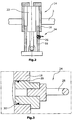
- a lifting column 14 is shown schematically.
- the lifting column 14 is connected to the machine frame 2. Further, the lifting column 14 is connected to the driving device 4, 6, wherein in Fig. 2 only a portion of the driving device 4, 6 is shown.
- the lifting column 14 has a column member 18 and a guide member 16, wherein in the height adjustment of the lifting column 14, the column member 18 by means of a piston-cylinder unit 22 telescopically in the guide element and executable.
- a receptacle 26 is provided, into which a locking member 24 is inserted such that the locking member 24 protrudes in the illustrated inserted state at least partially against the pillar member 18 to the outside.
- the receptacle 26 in the column member 18 may, as in the illustrated embodiment, be a bore.
- the locking element 24 may, as in the illustrated embodiment, be a bolt element.
- the locking element 24 may have a securing element 30 which is clamped when inserted into the receptacle 26 and thus prevents slippage of the locking element 24 relative to the column member 18 in the inserted state.
- the illustrated fuse element may be an O-ring. This is arranged in a circumferential groove on the locking element 24. The O-ring is preferably opposite the locking element 24 and is clamped during insertion. In this way, a slipping of the locking element 24 relative to the column member 18 is prevented in the inserted state.
- the locking element 24 also has a ring element 28. With the help of this ring element 28, the locking element 24 better from the recording 26 are pulled out and / or better introduced. Locking element 24 and ring element 28 may be made of one piece, or as shown assembled from different elements.
- the construction machine 1 can be transferred to a first maintenance position.
- a height adjustment of at least one lifting column 14 of the construction machine 1 wherein in the height adjustment of the lifting column 14 of the machine frame 2 is moved relative to the floor covering 29.
- the column member 18 of the lifting column 14 telescopically in the in Fig. 2 illustrated guide member 16 of the lifting column 14 on or executed.
- the lifting column can move the machine frame 2, for example by extending the piston-cylinder unit 22 and downward movement of the column member 18 relative to the guide member 16 of the lifting column in a first maintenance position. Due to the rising on the floor covering 29 driving device 4,6 is raised by the relative movement of the column member 18 to guide member 16 of the machine frame 2 relative to the floor covering.
- the locking element 24 Upon reaching or after reaching the first maintenance position, the locking element 24 is inserted into the receptacle 26 of the column member 18 such that the locking member in the inserted state at least partially protrudes from the column member 18 and limits a further height adjustment of the lifting column 14 at least in one direction.
- Fig. 4 is shown as the locking member 24 limits a further height adjustment of the lifting column 14 in at least one direction.
- the guide member 16 abuts against the protruding part of the locking member 24. In this way, sagging of the machine frame 2 beyond the locking element is prevented during maintenance.
- the locking element 24 may have a stepped recess 32 having a support surface 34. As in Fig. 4 is shown, the guide member 16 rests on the support surface 34.
- the machine frame 2 is first moved into a first maintenance position, in which the locking element 24, as described, is inserted into the receptacle 26 of the pillar element 18. Then the lifting column 14 can be adjusted in height, so that the machine frame is lowered relative to the first maintenance position in a second maintenance position is, wherein in the second maintenance position, the guide member 16, as in Fig. 4 shown rests on the support surface 34 of the locking element 24.
- the resting of the guide member 16 additionally secures slipping out of the locking element 24, since the guide member 16 is at least partially against at least a portion of the locking element 24 which is inserted in the receptacle 26, so that in this State the locking element 24 can not be pulled out of the receptacle 26.
- the column member may, as shown, cylindrical in shape and preferably be a hollow cylinder.
- the height adjustment of the lifting column 14 can be effected via a piston-cylinder unit 22, in particular a hydraulic cylinder.
- the column member 18 preferably has a cylinder axis 36.
- the formed as a bore receptacle 26 extends substantially perpendicular to the cylinder axis 36.
- the formed as a bore receptacle 26 is in the illustrated embodiment according to Fig. 5 a continuous bore through the entire column member 18.
- the through bore extends at a distance from the cylinder axis 36.
- the locking member 24 may be a rod member as shown in FIG Fig. 5 is shown. This rod member may be inserted into the through bore such that the rod member projects beyond the column member 18 at two locations.
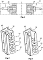
- a further alternative embodiment is shown, in which a plurality of receptacles 26 are provided on the column member 18, in each of which a locking element 24 is inserted. It is understood that the receptacles 26 can also be provided at a vertical distance from each other. In this way, the locking elements can be attached to the pillar member at different heights relative to the floor covering 29. Thus, the limitation of the height adjustment can be adapted to different maintenance tasks.
- a storage container 38 is shown. This is preferably arranged on the machine frame 2.
- at least one locking element 24 can be inserted.
- a plurality of locking elements 24 can be inserted into the storage container 38.
- the storage container 38 has a switching element 40, which allows commissioning of the construction machine 1 only when the switching element 40 has been actuated. This takes place only when all locking elements 24 are inserted into the storage container 38.
- Fig. 8 an embodiment is shown in which a locking element has been removed.
- the switching element 40 would prevent the construction machine 1 from being put into operation.
Landscapes
- Engineering & Computer Science (AREA)
- Mechanical Engineering (AREA)
- Chemical & Material Sciences (AREA)
- Combustion & Propulsion (AREA)
- Transportation (AREA)
- Architecture (AREA)
- Civil Engineering (AREA)
- Structural Engineering (AREA)
- Road Paving Machines (AREA)
- Component Parts Of Construction Machinery (AREA)
- Conveying And Assembling Of Building Elements In Situ (AREA)
- Road Repair (AREA)
Applications Claiming Priority (1)
| Application Number | Priority Date | Filing Date | Title |
|---|---|---|---|
| DE102016225189.9A DE102016225189A1 (de) | 2016-12-15 | 2016-12-15 | Baumaschine für die Bearbeitung von einem Bodenbelag |
Publications (2)
| Publication Number | Publication Date |
|---|---|
| EP3336254A1 true EP3336254A1 (fr) | 2018-06-20 |
| EP3336254B1 EP3336254B1 (fr) | 2019-08-28 |
Family
ID=60629502
Family Applications (1)
| Application Number | Title | Priority Date | Filing Date |
|---|---|---|---|
| EP17205859.6A Active EP3336254B1 (fr) | 2016-12-15 | 2017-12-07 | Engin de construction et procédé de conversion de l'engin de construction pour l'usinage d'un revêtement de sol |
Country Status (4)
| Country | Link |
|---|---|
| US (1) | US10577036B2 (fr) |
| EP (1) | EP3336254B1 (fr) |
| CN (2) | CN207714099U (fr) |
| DE (1) | DE102016225189A1 (fr) |
Families Citing this family (6)
| Publication number | Priority date | Publication date | Assignee | Title |
|---|---|---|---|---|
| DE102016225189A1 (de) | 2016-12-15 | 2018-06-21 | Wirtgen Gmbh | Baumaschine für die Bearbeitung von einem Bodenbelag |
| DE102018010153B4 (de) * | 2018-12-28 | 2021-10-28 | Bomag Gmbh | Baumaschine, insbesondere Straßenfräse, sowie Verfahren zur Steuerung der Hubposition einer Kolben-Zylinder-Einheit einer Hubsäule einer Baumaschine |
| CN112810710B (zh) * | 2019-02-25 | 2022-09-06 | 泉州市比邻三维科技有限公司 | 一种方便转向的3d打印机器人的履带式行走装置 |
| CN112389555A (zh) * | 2020-11-25 | 2021-02-23 | 三一重机有限公司 | 引导轮机构、驱动装置和挖掘机 |
| DE102021118680A1 (de) | 2021-04-06 | 2022-10-06 | Bomag Gmbh | Bodenfräsmaschine |
| US11851832B2 (en) * | 2021-12-20 | 2023-12-26 | Caterpillar Paving Products Inc. | Machine service set position control system |
Citations (4)
| Publication number | Priority date | Publication date | Assignee | Title |
|---|---|---|---|---|
| EP1924746A1 (fr) * | 2005-09-12 | 2008-05-28 | Wirtgen GmbH | Engin de chantier autotracte, et colonne de levage d'un engin de chantier |
| EP2011921A2 (fr) * | 2007-07-05 | 2009-01-07 | Wirtgen GmbH | Dispositif de fraisage de route automobile, en particulier grande fraiseuse |
| EP2698475A1 (fr) * | 2012-08-16 | 2014-02-19 | Wirtgen GmbH | Engin automobile et procédé de fonctionnement d'un engin automobile |
| EP2886719A1 (fr) * | 2002-01-30 | 2015-06-24 | Wirtgen GmbH | Engin |
Family Cites Families (7)
| Publication number | Priority date | Publication date | Assignee | Title |
|---|---|---|---|---|
| DE8604868U1 (de) | 1986-02-22 | 1986-04-10 | Eßmann, Johannes Wilhelm, 4100 Duisburg | Traggestell zum Anheben von Fahrzeugen |
| WO2005082068A2 (fr) * | 2004-02-25 | 2005-09-09 | Hamm Alton B | Systeme de commande de la stabilite d'un vehicule |
| DE102012205005B4 (de) | 2012-03-28 | 2015-04-02 | Wirtgen Gmbh | Selbstfahrende Fräsmaschine, Verwendung einer Hubsäule einer Fräsmaschine, sowie Verfahren zum Erhöhen der Arbeitseffektivität einer Fräsmaschine |
| US9296273B2 (en) * | 2013-10-14 | 2016-03-29 | Agco Corporation | Machine suspension and height adjustment |
| DE102014019168A1 (de) * | 2014-12-19 | 2016-06-23 | Bomag Gmbh | BAUMASCHINE, INSBESONDERE STRAßENFRÄSE, UND VERFAHREN ZUM AUSGLEICHEN VON BODENUNEBENHEITEN FÜR EINE SOLCHE BAUMASCHINE |
| CN105291264A (zh) * | 2015-11-19 | 2016-02-03 | 长沙拓湃工程机械设备有限公司 | 辅助升降支腿、升降方法及工程机械 |
| DE102016225189A1 (de) * | 2016-12-15 | 2018-06-21 | Wirtgen Gmbh | Baumaschine für die Bearbeitung von einem Bodenbelag |
-
2016
- 2016-12-15 DE DE102016225189.9A patent/DE102016225189A1/de not_active Withdrawn
-
2017
- 2017-12-07 EP EP17205859.6A patent/EP3336254B1/fr active Active
- 2017-12-08 CN CN201721709326.7U patent/CN207714099U/zh active Active
- 2017-12-08 CN CN201711298838.3A patent/CN108221596B/zh active Active
- 2017-12-11 US US15/836,994 patent/US10577036B2/en active Active
Patent Citations (4)
| Publication number | Priority date | Publication date | Assignee | Title |
|---|---|---|---|---|
| EP2886719A1 (fr) * | 2002-01-30 | 2015-06-24 | Wirtgen GmbH | Engin |
| EP1924746A1 (fr) * | 2005-09-12 | 2008-05-28 | Wirtgen GmbH | Engin de chantier autotracte, et colonne de levage d'un engin de chantier |
| EP2011921A2 (fr) * | 2007-07-05 | 2009-01-07 | Wirtgen GmbH | Dispositif de fraisage de route automobile, en particulier grande fraiseuse |
| EP2698475A1 (fr) * | 2012-08-16 | 2014-02-19 | Wirtgen GmbH | Engin automobile et procédé de fonctionnement d'un engin automobile |
Also Published As
| Publication number | Publication date |
|---|---|
| CN108221596B (zh) | 2020-12-22 |
| EP3336254B1 (fr) | 2019-08-28 |
| CN207714099U (zh) | 2018-08-10 |
| US10577036B2 (en) | 2020-03-03 |
| CN108221596A (zh) | 2018-06-29 |
| DE102016225189A1 (de) | 2018-06-21 |
| US20180170462A1 (en) | 2018-06-21 |
Similar Documents
| Publication | Publication Date | Title |
|---|---|---|
| EP3336254A1 (fr) | Engin de construction et procédé de conversion de l'engin de construction pour l'usinage d'un revêtement de sol | |
| DE10308538C5 (de) | Verfahren zum Herstellen einer Schlitzwand im Boden, Schlitzwandfräse und Schlitzwandfräsvorrichtung | |
| EP3583061B1 (fr) | Dispositif de retenue | |
| DE2212875B2 (de) | Vorrichtung zum Festspannen, Lösen und Auswechseln von Werkzeugköpfen an einer Schwerwerkzeugmaschine | |
| DE2442139A1 (de) | Verfahren zur bearbeitung eines werkstueckes auf der drehbank und werkzeughalter zur durchfuehrung dieses verfahrens | |
| DE3507817A1 (de) | Bohrer zur erzeugung einer hinterschneidung in einer bohrung | |
| DE2919870A1 (de) | Bohreinrichtung, insbesondere erdoelbohreinrichtung | |
| DE102013223293A1 (de) | Honwerkzeug und Verfahren zum Bearbeiten mehrerer koaxialer Bohrungen | |
| EP3551565B1 (fr) | Support de pieds sur rails pour fixer un rail d'ascenseur | |
| DE19653761A1 (de) | Rundstrickmaschine mit auswechselbarem Nadelträger, z. B. Nadelzylinder | |
| DE102006062771B4 (de) | Hubstützenbock, insbesondere für einen Universaltragrahmen | |
| DE102004020228A1 (de) | Spannzylinder und Spannsystem | |
| DE2624079A1 (de) | Verfahren zur bildung von loechern mit ausgewaehlter aeusserer gestalt in gestein oder boden und bohrmaschine zur durchfuehrung des verfahrens | |
| DE2736733C2 (de) | Zusatzgerät für Schraubenspannvorrichtungen, vorzugsweise von Reaktordruckbehältern | |
| DE3906616A1 (de) | Montageeinrichtung zum automatischen fuegen von aggregaten von der unterseite her mit einer kfz-karosserie | |
| DE102005026554B4 (de) | Verfahren zum Einbringen einer Verriegelungsnut in eine Nutflanke | |
| EP3015414A1 (fr) | Moyen de suspension de charge | |
| CH712345B1 (de) | Vorrichtung mit einer Halteeinrichtung für die Positionierung einer Schraubenmutter einer Schraubenverbindung bei Überkopfmontage. | |
| DE102014103138B4 (de) | Drehräummaschine | |
| DE2936003C2 (de) | Mit Endringen versehene Zylinderschablone für Siebdruckmaschinen | |
| DE102010048956A1 (de) | Vorrichtung und Verfahren zur Befestigung eines mindestens eine Öffnung aufweisenden Bauteils an einem Trägerteil | |
| DE2649524A1 (de) | Teleskopartige vorrichtung | |
| EP3259981B1 (fr) | Foret pour fabrication à la machine de trous pour plantes | |
| DE3200540C2 (de) | Vorrichtung zum Verschließen von Behältern mit Stöpseln | |
| DE202021100630U1 (de) | Montagegerechtes Pressengestell |
Legal Events
| Date | Code | Title | Description |
|---|---|---|---|
| PUAI | Public reference made under article 153(3) epc to a published international application that has entered the european phase |
Free format text: ORIGINAL CODE: 0009012 |
|
| STAA | Information on the status of an ep patent application or granted ep patent |
Free format text: STATUS: THE APPLICATION HAS BEEN PUBLISHED |
|
| AK | Designated contracting states |
Kind code of ref document: A1 Designated state(s): AL AT BE BG CH CY CZ DE DK EE ES FI FR GB GR HR HU IE IS IT LI LT LU LV MC MK MT NL NO PL PT RO RS SE SI SK SM TR |
|
| AX | Request for extension of the european patent |
Extension state: BA ME |
|
| STAA | Information on the status of an ep patent application or granted ep patent |
Free format text: STATUS: REQUEST FOR EXAMINATION WAS MADE |
|
| 17P | Request for examination filed |
Effective date: 20181219 |
|
| RBV | Designated contracting states (corrected) |
Designated state(s): AL AT BE BG CH CY CZ DE DK EE ES FI FR GB GR HR HU IE IS IT LI LT LU LV MC MK MT NL NO PL PT RO RS SE SI SK SM TR |
|
| GRAP | Despatch of communication of intention to grant a patent |
Free format text: ORIGINAL CODE: EPIDOSNIGR1 |
|
| STAA | Information on the status of an ep patent application or granted ep patent |
Free format text: STATUS: GRANT OF PATENT IS INTENDED |
|
| RIC1 | Information provided on ipc code assigned before grant |
Ipc: B62D 55/084 20060101ALI20190207BHEP Ipc: E01C 23/088 20060101ALI20190207BHEP Ipc: E01C 23/00 20060101AFI20190207BHEP Ipc: B62D 55/065 20060101ALI20190207BHEP Ipc: B62D 55/00 20060101ALI20190207BHEP |
|
| INTG | Intention to grant announced |
Effective date: 20190308 |
|
| GRAS | Grant fee paid |
Free format text: ORIGINAL CODE: EPIDOSNIGR3 |
|
| GRAA | (expected) grant |
Free format text: ORIGINAL CODE: 0009210 |
|
| STAA | Information on the status of an ep patent application or granted ep patent |
Free format text: STATUS: THE PATENT HAS BEEN GRANTED |
|
| AK | Designated contracting states |
Kind code of ref document: B1 Designated state(s): AL AT BE BG CH CY CZ DE DK EE ES FI FR GB GR HR HU IE IS IT LI LT LU LV MC MK MT NL NO PL PT RO RS SE SI SK SM TR |
|
| REG | Reference to a national code |
Ref country code: GB Ref legal event code: FG4D Free format text: NOT ENGLISH |
|
| REG | Reference to a national code |
Ref country code: CH Ref legal event code: EP |
|
| REG | Reference to a national code |
Ref country code: DE Ref legal event code: R096 Ref document number: 502017002152 Country of ref document: DE |
|
| REG | Reference to a national code |
Ref country code: AT Ref legal event code: REF Ref document number: 1172571 Country of ref document: AT Kind code of ref document: T Effective date: 20190915 |
|
| REG | Reference to a national code |
Ref country code: IE Ref legal event code: FG4D Free format text: LANGUAGE OF EP DOCUMENT: GERMAN |
|
| REG | Reference to a national code |
Ref country code: SE Ref legal event code: TRGR |
|
| REG | Reference to a national code |
Ref country code: NL Ref legal event code: MP Effective date: 20190828 |
|
| REG | Reference to a national code |
Ref country code: LT Ref legal event code: MG4D |
|
| PG25 | Lapsed in a contracting state [announced via postgrant information from national office to epo] |
Ref country code: NO Free format text: LAPSE BECAUSE OF FAILURE TO SUBMIT A TRANSLATION OF THE DESCRIPTION OR TO PAY THE FEE WITHIN THE PRESCRIBED TIME-LIMIT Effective date: 20191128 Ref country code: FI Free format text: LAPSE BECAUSE OF FAILURE TO SUBMIT A TRANSLATION OF THE DESCRIPTION OR TO PAY THE FEE WITHIN THE PRESCRIBED TIME-LIMIT Effective date: 20190828 Ref country code: HR Free format text: LAPSE BECAUSE OF FAILURE TO SUBMIT A TRANSLATION OF THE DESCRIPTION OR TO PAY THE FEE WITHIN THE PRESCRIBED TIME-LIMIT Effective date: 20190828 Ref country code: LT Free format text: LAPSE BECAUSE OF FAILURE TO SUBMIT A TRANSLATION OF THE DESCRIPTION OR TO PAY THE FEE WITHIN THE PRESCRIBED TIME-LIMIT Effective date: 20190828 Ref country code: PT Free format text: LAPSE BECAUSE OF FAILURE TO SUBMIT A TRANSLATION OF THE DESCRIPTION OR TO PAY THE FEE WITHIN THE PRESCRIBED TIME-LIMIT Effective date: 20191230 Ref country code: NL Free format text: LAPSE BECAUSE OF FAILURE TO SUBMIT A TRANSLATION OF THE DESCRIPTION OR TO PAY THE FEE WITHIN THE PRESCRIBED TIME-LIMIT Effective date: 20190828 Ref country code: BG Free format text: LAPSE BECAUSE OF FAILURE TO SUBMIT A TRANSLATION OF THE DESCRIPTION OR TO PAY THE FEE WITHIN THE PRESCRIBED TIME-LIMIT Effective date: 20191128 |
|
| PG25 | Lapsed in a contracting state [announced via postgrant information from national office to epo] |
Ref country code: AL Free format text: LAPSE BECAUSE OF FAILURE TO SUBMIT A TRANSLATION OF THE DESCRIPTION OR TO PAY THE FEE WITHIN THE PRESCRIBED TIME-LIMIT Effective date: 20190828 Ref country code: ES Free format text: LAPSE BECAUSE OF FAILURE TO SUBMIT A TRANSLATION OF THE DESCRIPTION OR TO PAY THE FEE WITHIN THE PRESCRIBED TIME-LIMIT Effective date: 20190828 Ref country code: LV Free format text: LAPSE BECAUSE OF FAILURE TO SUBMIT A TRANSLATION OF THE DESCRIPTION OR TO PAY THE FEE WITHIN THE PRESCRIBED TIME-LIMIT Effective date: 20190828 Ref country code: IS Free format text: LAPSE BECAUSE OF FAILURE TO SUBMIT A TRANSLATION OF THE DESCRIPTION OR TO PAY THE FEE WITHIN THE PRESCRIBED TIME-LIMIT Effective date: 20191228 Ref country code: RS Free format text: LAPSE BECAUSE OF FAILURE TO SUBMIT A TRANSLATION OF THE DESCRIPTION OR TO PAY THE FEE WITHIN THE PRESCRIBED TIME-LIMIT Effective date: 20190828 Ref country code: GR Free format text: LAPSE BECAUSE OF FAILURE TO SUBMIT A TRANSLATION OF THE DESCRIPTION OR TO PAY THE FEE WITHIN THE PRESCRIBED TIME-LIMIT Effective date: 20191129 |
|
| PG25 | Lapsed in a contracting state [announced via postgrant information from national office to epo] |
Ref country code: TR Free format text: LAPSE BECAUSE OF FAILURE TO SUBMIT A TRANSLATION OF THE DESCRIPTION OR TO PAY THE FEE WITHIN THE PRESCRIBED TIME-LIMIT Effective date: 20190828 |
|
| PG25 | Lapsed in a contracting state [announced via postgrant information from national office to epo] |
Ref country code: RO Free format text: LAPSE BECAUSE OF FAILURE TO SUBMIT A TRANSLATION OF THE DESCRIPTION OR TO PAY THE FEE WITHIN THE PRESCRIBED TIME-LIMIT Effective date: 20190828 Ref country code: PL Free format text: LAPSE BECAUSE OF FAILURE TO SUBMIT A TRANSLATION OF THE DESCRIPTION OR TO PAY THE FEE WITHIN THE PRESCRIBED TIME-LIMIT Effective date: 20190828 Ref country code: EE Free format text: LAPSE BECAUSE OF FAILURE TO SUBMIT A TRANSLATION OF THE DESCRIPTION OR TO PAY THE FEE WITHIN THE PRESCRIBED TIME-LIMIT Effective date: 20190828 Ref country code: DK Free format text: LAPSE BECAUSE OF FAILURE TO SUBMIT A TRANSLATION OF THE DESCRIPTION OR TO PAY THE FEE WITHIN THE PRESCRIBED TIME-LIMIT Effective date: 20190828 |
|
| PG25 | Lapsed in a contracting state [announced via postgrant information from national office to epo] |
Ref country code: CZ Free format text: LAPSE BECAUSE OF FAILURE TO SUBMIT A TRANSLATION OF THE DESCRIPTION OR TO PAY THE FEE WITHIN THE PRESCRIBED TIME-LIMIT Effective date: 20190828 Ref country code: SM Free format text: LAPSE BECAUSE OF FAILURE TO SUBMIT A TRANSLATION OF THE DESCRIPTION OR TO PAY THE FEE WITHIN THE PRESCRIBED TIME-LIMIT Effective date: 20190828 Ref country code: IS Free format text: LAPSE BECAUSE OF FAILURE TO SUBMIT A TRANSLATION OF THE DESCRIPTION OR TO PAY THE FEE WITHIN THE PRESCRIBED TIME-LIMIT Effective date: 20200224 Ref country code: SK Free format text: LAPSE BECAUSE OF FAILURE TO SUBMIT A TRANSLATION OF THE DESCRIPTION OR TO PAY THE FEE WITHIN THE PRESCRIBED TIME-LIMIT Effective date: 20190828 |
|
| REG | Reference to a national code |
Ref country code: DE Ref legal event code: R097 Ref document number: 502017002152 Country of ref document: DE |
|
| PLBE | No opposition filed within time limit |
Free format text: ORIGINAL CODE: 0009261 |
|
| STAA | Information on the status of an ep patent application or granted ep patent |
Free format text: STATUS: NO OPPOSITION FILED WITHIN TIME LIMIT |
|
| PG2D | Information on lapse in contracting state deleted |
Ref country code: IS |
|
| 26N | No opposition filed |
Effective date: 20200603 |
|
| REG | Reference to a national code |
Ref country code: BE Ref legal event code: MM Effective date: 20191231 |
|
| PG25 | Lapsed in a contracting state [announced via postgrant information from national office to epo] |
Ref country code: MC Free format text: LAPSE BECAUSE OF FAILURE TO SUBMIT A TRANSLATION OF THE DESCRIPTION OR TO PAY THE FEE WITHIN THE PRESCRIBED TIME-LIMIT Effective date: 20190828 Ref country code: SI Free format text: LAPSE BECAUSE OF FAILURE TO SUBMIT A TRANSLATION OF THE DESCRIPTION OR TO PAY THE FEE WITHIN THE PRESCRIBED TIME-LIMIT Effective date: 20190828 |
|
| PG25 | Lapsed in a contracting state [announced via postgrant information from national office to epo] |
Ref country code: IE Free format text: LAPSE BECAUSE OF NON-PAYMENT OF DUE FEES Effective date: 20191207 Ref country code: LU Free format text: LAPSE BECAUSE OF NON-PAYMENT OF DUE FEES Effective date: 20191207 |
|
| PG25 | Lapsed in a contracting state [announced via postgrant information from national office to epo] |
Ref country code: BE Free format text: LAPSE BECAUSE OF NON-PAYMENT OF DUE FEES Effective date: 20191231 |
|
| PG25 | Lapsed in a contracting state [announced via postgrant information from national office to epo] |
Ref country code: CY Free format text: LAPSE BECAUSE OF FAILURE TO SUBMIT A TRANSLATION OF THE DESCRIPTION OR TO PAY THE FEE WITHIN THE PRESCRIBED TIME-LIMIT Effective date: 20190828 |
|
| PG25 | Lapsed in a contracting state [announced via postgrant information from national office to epo] |
Ref country code: HU Free format text: LAPSE BECAUSE OF FAILURE TO SUBMIT A TRANSLATION OF THE DESCRIPTION OR TO PAY THE FEE WITHIN THE PRESCRIBED TIME-LIMIT; INVALID AB INITIO Effective date: 20171207 Ref country code: MT Free format text: LAPSE BECAUSE OF FAILURE TO SUBMIT A TRANSLATION OF THE DESCRIPTION OR TO PAY THE FEE WITHIN THE PRESCRIBED TIME-LIMIT Effective date: 20190828 |
|
| REG | Reference to a national code |
Ref country code: CH Ref legal event code: PL |
|
| PG25 | Lapsed in a contracting state [announced via postgrant information from national office to epo] |
Ref country code: LI Free format text: LAPSE BECAUSE OF NON-PAYMENT OF DUE FEES Effective date: 20201231 Ref country code: CH Free format text: LAPSE BECAUSE OF NON-PAYMENT OF DUE FEES Effective date: 20201231 |
|
| PG25 | Lapsed in a contracting state [announced via postgrant information from national office to epo] |
Ref country code: MK Free format text: LAPSE BECAUSE OF FAILURE TO SUBMIT A TRANSLATION OF THE DESCRIPTION OR TO PAY THE FEE WITHIN THE PRESCRIBED TIME-LIMIT Effective date: 20190828 |
|
| PGFP | Annual fee paid to national office [announced via postgrant information from national office to epo] |
Ref country code: IT Payment date: 20221230 Year of fee payment: 6 |
|
| P01 | Opt-out of the competence of the unified patent court (upc) registered |
Effective date: 20230525 |
|
| PGFP | Annual fee paid to national office [announced via postgrant information from national office to epo] |
Ref country code: GB Payment date: 20231220 Year of fee payment: 7 |
|
| PGFP | Annual fee paid to national office [announced via postgrant information from national office to epo] |
Ref country code: SE Payment date: 20231219 Year of fee payment: 7 Ref country code: FR Payment date: 20231219 Year of fee payment: 7 Ref country code: DE Payment date: 20231214 Year of fee payment: 7 |
|
| REG | Reference to a national code |
Ref country code: AT Ref legal event code: MM01 Ref document number: 1172571 Country of ref document: AT Kind code of ref document: T Effective date: 20221207 |
|
| PG25 | Lapsed in a contracting state [announced via postgrant information from national office to epo] |
Ref country code: AT Free format text: LAPSE BECAUSE OF NON-PAYMENT OF DUE FEES Effective date: 20221207 |
|
| PG25 | Lapsed in a contracting state [announced via postgrant information from national office to epo] |
Ref country code: AT Free format text: LAPSE BECAUSE OF NON-PAYMENT OF DUE FEES Effective date: 20221207 |