EP3336003B1 - Separable container cap - Google Patents
Separable container cap Download PDFInfo
- Publication number
- EP3336003B1 EP3336003B1 EP17167758.6A EP17167758A EP3336003B1 EP 3336003 B1 EP3336003 B1 EP 3336003B1 EP 17167758 A EP17167758 A EP 17167758A EP 3336003 B1 EP3336003 B1 EP 3336003B1
- Authority
- EP
- European Patent Office
- Prior art keywords
- container
- cut
- display ring
- cap
- container cap
- Prior art date
- Legal status (The legal status is an assumption and is not a legal conclusion. Google has not performed a legal analysis and makes no representation as to the accuracy of the status listed.)
- Active
Links
Images


Classifications
-
- B—PERFORMING OPERATIONS; TRANSPORTING
- B65—CONVEYING; PACKING; STORING; HANDLING THIN OR FILAMENTARY MATERIAL
- B65D—CONTAINERS FOR STORAGE OR TRANSPORT OF ARTICLES OR MATERIALS, e.g. BAGS, BARRELS, BOTTLES, BOXES, CANS, CARTONS, CRATES, DRUMS, JARS, TANKS, HOPPERS, FORWARDING CONTAINERS; ACCESSORIES, CLOSURES, OR FITTINGS THEREFOR; PACKAGING ELEMENTS; PACKAGES
- B65D25/00—Details of other kinds or types of rigid or semi-rigid containers
- B65D25/38—Devices for discharging contents
- B65D25/40—Nozzles or spouts
- B65D25/42—Integral or attached nozzles or spouts
-
- B—PERFORMING OPERATIONS; TRANSPORTING
- B65—CONVEYING; PACKING; STORING; HANDLING THIN OR FILAMENTARY MATERIAL
- B65D—CONTAINERS FOR STORAGE OR TRANSPORT OF ARTICLES OR MATERIALS, e.g. BAGS, BARRELS, BOTTLES, BOXES, CANS, CARTONS, CRATES, DRUMS, JARS, TANKS, HOPPERS, FORWARDING CONTAINERS; ACCESSORIES, CLOSURES, OR FITTINGS THEREFOR; PACKAGING ELEMENTS; PACKAGES
- B65D41/00—Caps, e.g. crown caps or crown seals, i.e. members having parts arranged for engagement with the external periphery of a neck or wall defining a pouring opening or discharge aperture; Protective cap-like covers for closure members, e.g. decorative covers of metal foil or paper
- B65D41/32—Caps or cap-like covers with lines of weakness, tearing-strips, tags, or like opening or removal devices, e.g. to facilitate formation of pouring openings
- B65D41/34—Threaded or like caps or cap-like covers provided with tamper elements formed in, or attached to, the closure skirt
- B65D41/3442—Threaded or like caps or cap-like covers provided with tamper elements formed in, or attached to, the closure skirt with rigid bead or projections formed on the tamper element and coacting with bead or projections on the container
- B65D41/3447—Threaded or like caps or cap-like covers provided with tamper elements formed in, or attached to, the closure skirt with rigid bead or projections formed on the tamper element and coacting with bead or projections on the container the tamper element being integrally connected to the closure by means of bridges
-
- B—PERFORMING OPERATIONS; TRANSPORTING
- B65—CONVEYING; PACKING; STORING; HANDLING THIN OR FILAMENTARY MATERIAL
- B65D—CONTAINERS FOR STORAGE OR TRANSPORT OF ARTICLES OR MATERIALS, e.g. BAGS, BARRELS, BOTTLES, BOXES, CANS, CARTONS, CRATES, DRUMS, JARS, TANKS, HOPPERS, FORWARDING CONTAINERS; ACCESSORIES, CLOSURES, OR FITTINGS THEREFOR; PACKAGING ELEMENTS; PACKAGES
- B65D43/00—Lids or covers for rigid or semi-rigid containers
- B65D43/14—Non-removable lids or covers
- B65D43/16—Non-removable lids or covers hinged for upward or downward movement
-
- B—PERFORMING OPERATIONS; TRANSPORTING
- B65—CONVEYING; PACKING; STORING; HANDLING THIN OR FILAMENTARY MATERIAL
- B65D—CONTAINERS FOR STORAGE OR TRANSPORT OF ARTICLES OR MATERIALS, e.g. BAGS, BARRELS, BOTTLES, BOXES, CANS, CARTONS, CRATES, DRUMS, JARS, TANKS, HOPPERS, FORWARDING CONTAINERS; ACCESSORIES, CLOSURES, OR FITTINGS THEREFOR; PACKAGING ELEMENTS; PACKAGES
- B65D49/00—Arrangements or devices for preventing refilling of containers
- B65D49/12—Arrangements or devices for preventing refilling of containers by destroying, in the act of opening the container, an integral portion thereof
-
- B—PERFORMING OPERATIONS; TRANSPORTING
- B65—CONVEYING; PACKING; STORING; HANDLING THIN OR FILAMENTARY MATERIAL
- B65D—CONTAINERS FOR STORAGE OR TRANSPORT OF ARTICLES OR MATERIALS, e.g. BAGS, BARRELS, BOTTLES, BOXES, CANS, CARTONS, CRATES, DRUMS, JARS, TANKS, HOPPERS, FORWARDING CONTAINERS; ACCESSORIES, CLOSURES, OR FITTINGS THEREFOR; PACKAGING ELEMENTS; PACKAGES
- B65D55/00—Accessories for container closures not otherwise provided for
- B65D55/16—Devices preventing loss of removable closure members
-
- B—PERFORMING OPERATIONS; TRANSPORTING
- B65—CONVEYING; PACKING; STORING; HANDLING THIN OR FILAMENTARY MATERIAL
- B65D—CONTAINERS FOR STORAGE OR TRANSPORT OF ARTICLES OR MATERIALS, e.g. BAGS, BARRELS, BOTTLES, BOXES, CANS, CARTONS, CRATES, DRUMS, JARS, TANKS, HOPPERS, FORWARDING CONTAINERS; ACCESSORIES, CLOSURES, OR FITTINGS THEREFOR; PACKAGING ELEMENTS; PACKAGES
- B65D85/00—Containers, packaging elements or packages, specially adapted for particular articles or materials
- B65D85/70—Containers, packaging elements or packages, specially adapted for particular articles or materials for materials not otherwise provided for
- B65D85/72—Containers, packaging elements or packages, specially adapted for particular articles or materials for materials not otherwise provided for for edible or potable liquids, semiliquids, or plastic or pasty materials
-
- B—PERFORMING OPERATIONS; TRANSPORTING
- B65—CONVEYING; PACKING; STORING; HANDLING THIN OR FILAMENTARY MATERIAL
- B65D—CONTAINERS FOR STORAGE OR TRANSPORT OF ARTICLES OR MATERIALS, e.g. BAGS, BARRELS, BOTTLES, BOXES, CANS, CARTONS, CRATES, DRUMS, JARS, TANKS, HOPPERS, FORWARDING CONTAINERS; ACCESSORIES, CLOSURES, OR FITTINGS THEREFOR; PACKAGING ELEMENTS; PACKAGES
- B65D2251/00—Details relating to container closures
- B65D2251/10—Details of hinged closures
-
- B—PERFORMING OPERATIONS; TRANSPORTING
- B65—CONVEYING; PACKING; STORING; HANDLING THIN OR FILAMENTARY MATERIAL
- B65D—CONTAINERS FOR STORAGE OR TRANSPORT OF ARTICLES OR MATERIALS, e.g. BAGS, BARRELS, BOTTLES, BOXES, CANS, CARTONS, CRATES, DRUMS, JARS, TANKS, HOPPERS, FORWARDING CONTAINERS; ACCESSORIES, CLOSURES, OR FITTINGS THEREFOR; PACKAGING ELEMENTS; PACKAGES
- B65D2401/00—Tamper-indicating means
- B65D2401/15—Tearable part of the closure
- B65D2401/30—Tamper-ring remaining connected to closure after initial removal
-
- B—PERFORMING OPERATIONS; TRANSPORTING
- B65—CONVEYING; PACKING; STORING; HANDLING THIN OR FILAMENTARY MATERIAL
- B65D—CONTAINERS FOR STORAGE OR TRANSPORT OF ARTICLES OR MATERIALS, e.g. BAGS, BARRELS, BOTTLES, BOXES, CANS, CARTONS, CRATES, DRUMS, JARS, TANKS, HOPPERS, FORWARDING CONTAINERS; ACCESSORIES, CLOSURES, OR FITTINGS THEREFOR; PACKAGING ELEMENTS; PACKAGES
- B65D2565/00—Wrappers or flexible covers; Packaging materials of special type or form
- B65D2565/38—Packaging materials of special type or form
- B65D2565/381—Details of packaging materials of special type or form
- B65D2565/385—Details of packaging materials of special type or form especially suited for or with means facilitating recycling
Definitions
- the present disclosure relates to a container cap which is easily and separately collected and, more particularly, to a container cap which is easily and separately collected, in which when the container cap is opened for use, a state in which the container cap is connected to a container is maintained by a display ring, and when it is required to completely separate the container cap from the container for separate collection, the display ring is simply separated by a cut part by external force without a separate tool.
- a container in which beverage such as mineral water or liquid materials such as oil, paint and chemicals are accommodated has a protruding spout through which liquid materials are input/output.
- a container cap configured to open/close an opening of the spout is used to suppress input/output of the liquid materials.
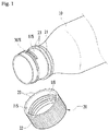
- Fig. 1 is a view illustrating a general container and a general container cap.
- a male screw M/S is formed on an outer peripheral surface E/S of a protruding spout of the container 10 and a female screw F/S is formed on an inner peripheral surface I/S of the covering cap 20 to correspond to the male screw M/S, so that the container 10 and the container cap 20 are screw-coupled to each other or are uncoupled from each other.
- the container cap 20 includes a display ring 21 caught by the spout of the container 10 to be prevented from being separated so as to identify whether the container 10 is used, and a cap body 22.
- cap body 22 and the display ring 21 are connected to each other along a circumference therebetween by a plurality of bridges 23.
- the bridges 23 are cut, and thus opening trails are generated.
- the display ring 21 is separated from the cap body 22 and remains while being caught by the spout of the container, and the cap body 22 is completely separated from the container.
- Korean Patent No. 10-1325850 (Packing container cap: hereinafter, referred to as "prior art 1"), which discloses a container cap according to the preamble of claim 1, and Korean Patent No. 10-1038894 (Packing container cap: hereinafter, referred to as "prior art 2").
- WO 2019/031779 which is prior art under Article 54(3) EPC, discloses in Fig.2 a lower display ring with a vertical cut part at its end.
- a container cap according to the prior art includes a cap body 22' and a portion, that is, a display ring 21', fixed to a container integrally formed at a lower portion of the cap body 22'.
- a plurality of bridges 23 are formed along a circumference between the cap body 22' and the display ring 21' except for a portion thereof, and a hinge 25 connecting the cap body 22' and the display ring 21' to each other is formed at the portion.
- the display ring 21' has a cut slit 24 formed by cutting the portion of the circumference, to define an extending length when the cap body 22' is separated from the container 10.
- the general container cap including the above-described prior arts 1 and 2 as well as the container is separately collected after liquid materials are completely consumed and is recycled.
- the container 10 is generally formed of polyethylene phthalate (PET), and further, the container caps 20 and 20' are generally formed of polypropylene (PP) or polyethylene (PE).
- PET polyethylene phthalate
- PP polypropylene
- PE polyethylene
- the container and the container cap are formed of different materials, and it is preferred that, to improve recycling efficiency, the container and the container cap are collected in accordance with materials to ensure properties of the corresponding materials.
- the container caps 20 and 20' according to the related art have a problem in that, because the display rings 21 and 21' are collected while being fixed to the container 10 after being used, the display rings 21 and 21 ' are recycled together with the container.
- a collection worker should perform an operation of cutting and separating the display rings 21 and 21' from the container 10 by using tools such as a knife and nippers.
- the present disclosure is conceived to solve the above-described problems, and an aspect of the present disclosure is to provide a container cap for easy separate collection, in which a display ring as well as a cap body may be completely separated from a spout of a container, so that recycling efficiency may be improved.
- a container cap which is easily and separately collected may include a cap body using a screw-coupling scheme and a display ring provided below the cap body to connect one hinge and a plurality of bridges to each other, and has a loss and free rotation preventing function.
- the display ring may have a cut part including cut bridges formed from one end or both ends of the cut slit in a lengthwise direction of the cut slit to a lower edge of the display ring.
- the display ring has an anti-shock hole formed between an end of the cut slit and an end of the cut part, the anti-shock hole being in contact with the end of the cut slit.
- a guide groove that is thinner than a thickness of the display ring may be formed in a portion of the cut part, in which the cut bridges are formed.
- the cut part may have a slope ⁇ at a cut slit end and is formed toward a lower edge of the display ring, at which the cut slit is not formed.
- the anti-shock hole of the cut part may have a diameter that is larger than a width formed by the cut slit, and an upper end of the anti-shock hole may be higher than an end of the cut slit.
- a container cap which is easily separated and collected has an effect that a user may completely separate a spout of a container and a display ring from each other only by applying external force pulling a cap body by a cut part formed at an end of a cut slit of the display ring, so that the container and the container cap having different materials may be discriminately, easily and separately collected.
- the present disclosure will be described with reference to a state in which a container having the container cap installed therein stands, that is, a state in which a spout of the container extends upward
- the expression “inside” refers to a central direction of an inside of the container at the corresponding height or a portion located in the direction
- the expression “outside” refers to a direction that is opposite to the inside or a portion located in the direction.
- the height refers to an interval between the container including the container cap and a floor in a state in which the container stands up.
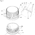
- Figs. 3 and 4 are perspective views illustrating a container cap which is easily and separately collected, according to the present disclosure
- Figs. 5A , 5B and 5C are an embodiment illustrating a usage state of the container cap which is easily and separately collected according to the present disclosure.
- a container cap 100 which is easily and separately collected, according to the present disclosure, may be completely separated from a container 10 after the container 10 is used, so that the container and the container cap having different materials may be separately collected and recycled.
- the container cap 100 which is easily and separately collected has a cut part 150 including cut bridges 152, the cut part 150 being formed at one or both cut slit ends 141 of the cut slit 140 to a lower edge of the display ring 120.
- a user may separate the display ring 120 from the container without a separate tool such as a knife and nippers.
- the container cap 100 which is easily and separately collected, according to the present disclosure, is coupled to a spout of a container in a screw-coupling scheme by a male screw M/S and a female screw F/S, which is identical to the general container cap according to the related art, and has an opening/closing structure for the container spout according thereto.
- the container cap 100 includes a cap body 110 separated by lifting-up in a screw-coupling scheme, and a display ring 120 connected to one hinge 130 at a lower portion of the cap body 110 by a plurality of bridges 121.
- the display ring 120 has a cut slit 140 on a lower side of the hinge 130, and the cut slit 140 is formed by cutting a partial section of a circumference (for example, a half of the circumference) of a central portion of the display ring 120 in the height direction thereof.
- a portion of the above-described display ring 120, in which the cut slit 140 is formed, is divided into an upper display ring 120a and a lower display ring 120b and, while being widened, enlarges a connection length between the cap body 110 and the display ring 120 so that the cap body 110 is opened while being connected to the display ring 120.
- a general usage state of a container cap using the above-described container cap may be identified. This corresponds to a well-known function, and thus, a detailed action relationship thereof will be omitted to make the subject matter of the present disclosure clear.
- the general container 10 and the general container cap 100 are manufactured of different materials, and after the container 10 is used, the container 10 and the container cap 100 are completely separated from each other as far as possible, so that a separate collection box may improve recycling efficiency.
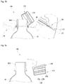
- the cut part 150 is formed downward from one or both cut slit ends 141 of the cut slit 140 of the display ring 120 to a lower edge thereof such that a user or a worker may completely separate the container cap 100 from the container 10 by easily applying external force without a separate tool such as a knife and nippers, as needed.
- the cut part 150 has a cut line formed by perforating one or more holes at a portion at which the cut line is to be formed, and the cut line is formed by a plurality of cut bridges 152 to be cut by applying external force.
- the display ring 120 when the cut part 150 is formed, the display ring 120 further has an anti-shock hole 151 formed between an end of the cut slit 140 and an end of the cut part 150 in contact with the cut slit 140.
- Such an anti-shock hole 151 serves to concentrate a direction of force to the upper display ring 120a, applied so as not to unintentionally cut the cut part 150, when the user opens the container cap 100, that is, when the display ring 120 is divided into the upper display ring 120a and the lower display ring 120b by the cut slit 140 and enlarges the connection length between the cap body 110 and the display ring 120 while being widened.
- the cut part 150 has a slope ⁇ at a cut slit end 141 and is formed toward a lower edge of the display ring 120 in which the cut slit 140 is not formed.
- a direction of force generated when the container cap 100 is opened by the anti-shock hole 151 does not face the cut part 150 but faces an end of the upper display ring 120a divided by the cut slit 140, in the display ring 120.
- the anti-shock hole 151 has a diameter that is larger than a width formed by the cut slit 1 40 so that the direction of force is formed upward, and it is preferred that an upper end of the anti-shock hole 1 51 is formed to be higher than an end of the cut slit 140.
- the cut part 150 is formed along a guide groove 153 of which a portion in which the cut bridges 152 are formed is thinner than the thickness of the display ring 120 such that the user or the worker easily separate the container cap 100 while holding the cap body 110 and applying force.
- the cut part 150 formed in the container cap 100 which is easily and separately collected, according to the present disclosure, is formed in consideration of the thickness and the strength of the container such that there is no fracture when the container cap 100 is coupled to the container 10 or the container 10 is opened, and when the user wants to completely separate the container cap 100 from the container 10, the design of the cut part 150 is sufficiently considered such that the cut part 150 may be cut by force pulling the cap body 110.
- the container cap 100 which is easily and separately collected includes a cap body 110 and a display ring 120 formed at a lower portion of the cap body 110 by connecting the hinge 130 and the bridges 121 to each other.
- the cut slit 140 is formed by cutting a portion of a circumference of a central portion of the display ring 120 in the height direction thereof, and the cut part 150 including the anti-shock hole 151, the cut bridges 152 and the guide groove 153 is downward formed at an end of the cut slit 140.
- the user grips and rotates the cap body 110 to open the container 10.
- the bridges 121 are cut and separated, and while the display ring 120 is fixed to the spout of the container, the cap body 110 is lifted up in a screw-coupling scheme, so that the spout of the container is opened.
- the upper display ring 120a divided by the cut slit 140 increases the connection length while being connected to the cap body 110, so that the cap body 110 may be opened.
- the cut part 150 has a slope ⁇ at the cut slit end 141 and is formed toward a lower edge of the display ring 120 in which the cut slit 140 is not formed, and the anti-shock hole 151 has a diameter that is larger than a width formed by the cut slit 140. It is preferred that an upper end of the anti-shock hole 151 is formed to be higher than an end of the cut slit 140.
- the cut part 150 is vertically formed at the cut slit end 141 toward a lower edge of the display ring 120, and it is apparent that this may be changed depending on the manufacturing and the design of the container cap 100.
- the user holds the cap body 110 and bends the display ring 120 in an opposite direction while the display ring 120 passes through the spout of the container.
- the cut part 150 is formed in a direction in which force is applied, and thus, the cut bridges 152 are separated and cut by external force.
- the container cap 100 is completely separated and escapes from the container 10, and the container 10 and the container cap 100 having different materials are separately collected.
- a usage state of the container cap 100 described in Figs. 5A to 5C is merely an embodiment for easily and completely separating the container cap 100 from the container 10 using the lowest force, and it is obvious that the user may pull the cap body 110 of the container cap 100 in a lateral direction without bending the cap body 110 of the container cap 100 so that the container cap 100 and the container 10 may be separated by the cut part 150.
- REFERENCE NUMERALS 10 Container 100: Container cap 110: Cap body 120: Display ring 120a: Upper display ring 120b: Lower display ring 121: Bridge 130: hinge 140: Cut slit 141: Cut slit end 150: Cut part 151: Anti-shock hole 152: Cut bridge 153: Guide groove
Landscapes
- Engineering & Computer Science (AREA)
- Mechanical Engineering (AREA)
- Closures For Containers (AREA)
Priority Applications (1)
| Application Number | Priority Date | Filing Date | Title |
|---|---|---|---|
| PL17167758T PL3336003T3 (pl) | 2016-12-16 | 2017-04-24 | Oddzielana pokrywka pojemnika |
Applications Claiming Priority (2)
| Application Number | Priority Date | Filing Date | Title |
|---|---|---|---|
| KR20160172922 | 2016-12-16 | ||
| KR1020170016328A KR101880107B1 (ko) | 2016-12-16 | 2017-02-06 | 분리수거가 용이한 용기 마개 |
Publications (2)
| Publication Number | Publication Date |
|---|---|
| EP3336003A1 EP3336003A1 (en) | 2018-06-20 |
| EP3336003B1 true EP3336003B1 (en) | 2020-04-08 |
Family
ID=58411234
Family Applications (1)
| Application Number | Title | Priority Date | Filing Date |
|---|---|---|---|
| EP17167758.6A Active EP3336003B1 (en) | 2016-12-16 | 2017-04-24 | Separable container cap |
Country Status (13)
| Country | Link |
|---|---|
| US (1) | US10654624B2 (pl) |
| EP (1) | EP3336003B1 (pl) |
| JP (1) | JP6921959B2 (pl) |
| KR (1) | KR101880107B1 (pl) |
| CN (2) | CN108202914B (pl) |
| DK (1) | DK3336003T3 (pl) |
| ES (1) | ES2802402T3 (pl) |
| HU (1) | HUE050135T2 (pl) |
| PH (1) | PH12019501382B1 (pl) |
| PL (1) | PL3336003T3 (pl) |
| PT (1) | PT3336003T (pl) |
| RU (1) | RU2720960C1 (pl) |
| WO (1) | WO2018111052A1 (pl) |
Families Citing this family (41)
| Publication number | Priority date | Publication date | Assignee | Title |
|---|---|---|---|---|
| TWI589498B (zh) * | 2015-04-02 | 2017-07-01 | 邁可約瑟夫 麥奎爾 | 容器用之蓋子 |
| US11312544B2 (en) | 2020-03-30 | 2022-04-26 | ThisCap, Inc. | Cap for container |
| US11332290B2 (en) | 2015-04-02 | 2022-05-17 | ThisCap, Inc. | Cap for container |
| KR101880107B1 (ko) * | 2016-12-16 | 2018-07-19 | 성보연 | 분리수거가 용이한 용기 마개 |
| US10836544B2 (en) | 2018-05-09 | 2020-11-17 | Silgan White Cap LLC | Closure with hinge |
| ES2712094B2 (es) * | 2018-06-12 | 2019-10-17 | Sanchez Jose Francisco Gonzalez | Tapón abatible para envases |
| US10654625B2 (en) * | 2018-10-12 | 2020-05-19 | Closure Systems International Inc. | Twist and flip lock closure |
| EP3880575B1 (en) * | 2018-11-12 | 2024-07-10 | Sidel Participations Sas | Tethered plastic screw stopper |
| KR20200001087U (ko) | 2018-11-19 | 2020-05-27 | 금성실업 주식회사 | 분리수거가 용이한 용기마개 |
| EP3938288B1 (de) * | 2019-03-11 | 2024-05-01 | ALPLA Werke Alwin Lehner GmbH & Co. KG | Behälterverschluss und behälter |
| EP3947180A1 (en) * | 2019-04-05 | 2022-02-09 | Nypro Inc. | Tethered cap and spout |
| WO2020212426A1 (de) * | 2019-04-15 | 2020-10-22 | Alpla Werke Alwin Lehner Gmbh & Co. Kg | Behälterverschluss |
| US11148847B2 (en) * | 2019-05-01 | 2021-10-19 | Pepsico, Inc. | Plastic neck outsert for metal beverage container |
| KR102045184B1 (ko) | 2019-05-02 | 2019-12-02 | 박세진 | 재활용을 위한 음료수병 마개 제거장치 |
| KR20200127355A (ko) | 2019-05-02 | 2020-11-11 | 박세진 | 재활용을 위한 페트병 마개 제거장치 |
| DE102019112259B3 (de) * | 2019-05-10 | 2020-04-09 | CCT - SYS GmbH | Schraubverschluss aus Kunststoff für Flaschen |
| CN111924311B (zh) | 2019-05-13 | 2023-02-17 | 赫斯基注塑系统有限公司 | 用于容器的封闭装置 |
| ES2914055T3 (es) * | 2019-05-21 | 2022-06-07 | Soc Lorraine De Capsules Metalliques Manufacture De Bouchage | Tapón de rosca destinado a permanecer fijado a un recipiente después de la apertura del recipiente |
| US11214413B2 (en) * | 2019-07-24 | 2022-01-04 | Silgan White Cap LLC | Tethered flip closure |
| WO2021046413A1 (en) | 2019-09-06 | 2021-03-11 | Silgan White Cap LLC | Tethered, hinged closure |
| USD1013512S1 (en) | 2019-10-10 | 2024-02-06 | Merrilee Kick | Container |
| EP3880578B1 (en) | 2019-10-11 | 2023-07-19 | Husky Injection Molding Systems Ltd. | Closure device for container |
| DE102019007519A1 (de) * | 2019-10-29 | 2021-04-29 | Gomez Cao Innovations & Inventions, S.L. | Eine Flasche oder Vorform für eine Flasche und ein Verschluss für eine Flasche |
| US20210179324A1 (en) * | 2019-12-13 | 2021-06-17 | Niagara Bottling, Llc | Tethered container closure |
| US12122561B2 (en) | 2020-01-16 | 2024-10-22 | Closure Systems International Inc. | Package with tethered closure |
| CH717100A2 (de) | 2020-01-31 | 2021-08-16 | Muehlemann Ip Gmbh | Drehverschlusseinrichtung zum Verschliessen einer Behältermündung. |
| KR102363696B1 (ko) * | 2020-05-20 | 2022-02-17 | 박수현 | 용기 개폐용 캡 |
| US11273964B2 (en) * | 2020-05-29 | 2022-03-15 | Silgan White Cap LLC | Hinged closure |
| US20220041339A1 (en) | 2020-08-07 | 2022-02-10 | Niagara Bottling, Llc | Single anchor closure |
| US12280921B2 (en) * | 2020-08-20 | 2025-04-22 | Sidel Participations Sas | Hinged closure |
| US11866231B2 (en) * | 2020-09-29 | 2024-01-09 | Novembal Usa Inc. | Hinged closure |
| US11975889B2 (en) | 2021-09-02 | 2024-05-07 | Merrilee Kick | Container apparatus |
| KR102457685B1 (ko) * | 2021-10-14 | 2022-10-24 | 양복주 | 이탈방지와 완전 분리가 가능한 구조를 갖는 친환경 캡 |
| EP4429966A4 (en) | 2021-11-08 | 2026-01-14 | Silgan White Cap LLC | PROJECTION ON THE NECK OF A CONTAINER |
| CA3247359A1 (en) | 2022-02-11 | 2023-08-17 | Silgan White Cap LLC | ATTACHED HINGE CLOSURE WITH MODIFIED PRIMARY SLOT |
| KR200499136Y1 (ko) * | 2022-04-22 | 2025-05-12 | 주식회사 올도완 | 유리병 커버 조립체 |
| KR102755253B1 (ko) | 2023-01-02 | 2025-01-21 | 주식회사농심 | 일체형 병뚜껑 및 이를 구비한 용기 |
| US12570442B2 (en) | 2023-05-09 | 2026-03-10 | Silgan White Cap LLC | Closure with pivotal cap |
| WO2024249620A1 (en) * | 2023-06-02 | 2024-12-05 | Silgan White Cap LLC | Closure with sequentially breaking connections |
| KR20240178522A (ko) | 2023-06-22 | 2024-12-31 | 윤행옥 | 표시 링 분리 구조의 플라스틱 병뚜껑 |
| KR20250031074A (ko) | 2023-08-25 | 2025-03-06 | 주식회사 더하나 | 분리가 용이한 포장용 병용 유출캡 |
Citations (1)
| Publication number | Priority date | Publication date | Assignee | Title |
|---|---|---|---|---|
| WO2019031779A1 (ko) * | 2017-03-07 | 2019-02-14 | 성보연 | 개방상태 유지기능을 갖는 용기마개 |
Family Cites Families (28)
| Publication number | Priority date | Publication date | Assignee | Title |
|---|---|---|---|---|
| FR1164846A (fr) * | 1957-01-18 | 1958-10-14 | Capsule ou bouchon imperdable | |
| FR2329536A1 (fr) * | 1973-07-02 | 1977-05-27 | Somepla Sa | Nouvelle capsule a vis inviolable et imperdable |
| FR2499519A1 (fr) * | 1981-02-11 | 1982-08-13 | Grussen Jean | Capsule de bouchage a vis avec anneau d'inviolabilite |
| US4557393A (en) * | 1984-04-17 | 1985-12-10 | Continental White Cap, Inc. | Snap-on cap with tethering strap |
| US4720018A (en) * | 1986-01-31 | 1988-01-19 | H-C Industries, Inc. | Scoring arrangement for a tamper-indicating plastic closure |
| US4798301A (en) * | 1987-12-14 | 1989-01-17 | Cap Snap Co. | Tamper-resistant cap for wide mouth jar |
| US5358131A (en) | 1992-06-19 | 1994-10-25 | H-C Industries, Inc. | Tamper-indicating plastic closure with segemented pilfer band |
| US5320234A (en) * | 1992-10-07 | 1994-06-14 | H-C Industries, Inc. | Tamper-indicating plastic closure with pilfer band having staggered scores |
| US5853095A (en) * | 1992-12-18 | 1998-12-29 | White Cap, Inc. | Tamper evident splitting closure |
| US5875942A (en) * | 1996-03-22 | 1999-03-02 | Japan Crown Cork Co., Ltd. | Hinged cap separable from bottle at the time of disposal |
| US7134567B2 (en) * | 2001-04-12 | 2006-11-14 | Ropak Corporation | Pull tab on tear strip on plastic cover plastic cover, including break tab feature, and related apparatus and methods |
| DE10146817A1 (de) * | 2001-09-20 | 2003-04-17 | Alcoa Deutschland Gmbh | Schraubverschluss |
| KR200308972Y1 (ko) * | 2002-12-11 | 2003-03-31 | 아성프라스틱공업 주식회사 | 용기 마개 |
| KR200308971Y1 (ko) * | 2002-12-11 | 2003-03-31 | 아성프라스틱공업 주식회사 | 개봉확인이 가능한 용기 마개 |
| US20050269281A1 (en) * | 2004-06-07 | 2005-12-08 | Mann-Lih Ding | Dual-purpose sealing cap for water buckets |
| CN102089220B (zh) * | 2008-07-08 | 2012-09-26 | 日本皇冠塞株式会社 | 合成树脂制容器盖 |
| KR20100003990U (ko) * | 2008-10-07 | 2010-04-15 | 주식회사 현우기술연구 | 탁주병 마개 |
| US8720716B2 (en) * | 2009-06-25 | 2014-05-13 | Phillip John Campbell | Closure with spring loaded tether docking |
| US8695822B2 (en) * | 2010-01-25 | 2014-04-15 | Si-Joong Kwon | Container for preventing loss of stopper and idle rotation thereof |
| KR100981240B1 (ko) * | 2010-03-23 | 2010-09-10 | 권시중 | 공회전 방지 버팀대가 구비된 포장용기 마개 |
| KR101038894B1 (ko) | 2010-01-28 | 2011-06-02 | 주식회사 그린캡 | 포장용기 마개 |
| EP2532602A1 (en) * | 2011-06-07 | 2012-12-12 | Nestec S.A. | A one-piece closure for equipping a container |
| KR101325850B1 (ko) | 2013-06-09 | 2013-11-05 | 권시중 | 포장용기 마개 |
| US9776779B2 (en) * | 2014-03-10 | 2017-10-03 | Phillip John Campbell | Closure with spring loaded tether docking |
| WO2016182305A1 (ko) * | 2015-05-11 | 2016-11-17 | 성보연 | 분실 및 자유회전 방지기능을 갖는 용기 마개 |
| KR20160132757A (ko) * | 2015-05-11 | 2016-11-21 | 성보연 | 분실 및 자유회전 방지기능을 갖는 용기 마개 |
| JP3205769U (ja) * | 2016-06-02 | 2016-08-12 | 株式会社三渓産業 | 容器用キャップ |
| KR101880107B1 (ko) * | 2016-12-16 | 2018-07-19 | 성보연 | 분리수거가 용이한 용기 마개 |
-
2017
- 2017-02-06 KR KR1020170016328A patent/KR101880107B1/ko active Active
- 2017-02-28 CN CN201710112456.0A patent/CN108202914B/zh active Active
- 2017-02-28 CN CN201720185748.2U patent/CN207360902U/zh active Active
- 2017-04-24 HU HUE17167758A patent/HUE050135T2/hu unknown
- 2017-04-24 ES ES17167758T patent/ES2802402T3/es active Active
- 2017-04-24 DK DK17167758.6T patent/DK3336003T3/da active
- 2017-04-24 EP EP17167758.6A patent/EP3336003B1/en active Active
- 2017-04-24 PT PT171677586T patent/PT3336003T/pt unknown
- 2017-04-24 PL PL17167758T patent/PL3336003T3/pl unknown
- 2017-05-02 US US15/584,034 patent/US10654624B2/en active Active
- 2017-12-18 JP JP2019533092A patent/JP6921959B2/ja active Active
- 2017-12-18 WO PCT/KR2017/014923 patent/WO2018111052A1/ko not_active Ceased
- 2017-12-18 PH PH1/2019/501382A patent/PH12019501382B1/en unknown
- 2017-12-18 RU RU2019118684A patent/RU2720960C1/ru active
Patent Citations (1)
| Publication number | Priority date | Publication date | Assignee | Title |
|---|---|---|---|---|
| WO2019031779A1 (ko) * | 2017-03-07 | 2019-02-14 | 성보연 | 개방상태 유지기능을 갖는 용기마개 |
Also Published As
| Publication number | Publication date |
|---|---|
| PH12019501382B1 (en) | 2024-02-14 |
| KR20170024589A (ko) | 2017-03-07 |
| WO2018111052A1 (ko) | 2018-06-21 |
| US20180170625A1 (en) | 2018-06-21 |
| ES2802402T3 (es) | 2021-01-19 |
| HUE050135T2 (hu) | 2020-11-30 |
| CN108202914A (zh) | 2018-06-26 |
| CN207360902U (zh) | 2018-05-15 |
| DK3336003T3 (da) | 2020-07-13 |
| CN108202914B (zh) | 2020-03-06 |
| PH12019501382A1 (en) | 2020-01-20 |
| PL3336003T3 (pl) | 2020-11-30 |
| KR101880107B1 (ko) | 2018-07-19 |
| EP3336003A1 (en) | 2018-06-20 |
| RU2720960C1 (ru) | 2020-05-15 |
| US10654624B2 (en) | 2020-05-19 |
| JP2020501998A (ja) | 2020-01-23 |
| PT3336003T (pt) | 2020-07-03 |
| JP6921959B2 (ja) | 2021-08-18 |
Similar Documents
| Publication | Publication Date | Title |
|---|---|---|
| EP3336003B1 (en) | Separable container cap | |
| KR102195928B1 (ko) | 개방상태 유지기능을 갖는 용기마개 | |
| US10806309B2 (en) | Disinfecting wipes dispenser | |
| JP6793263B2 (ja) | 多目的エコキャップ | |
| US10556718B2 (en) | End closure with a ring pull actuated secondary vent | |
| US20180317720A1 (en) | Disinfecting wipes dispenser | |
| KR20170103737A (ko) | 분실 및 자유회전 방지기능을 갖는 용기 마개 | |
| EP3689774A1 (en) | Container cap having function of maintaining open state | |
| EP1818272A1 (en) | Tamper-proof overcap for bottles | |
| US4066190A (en) | Container with collapsible pouring spout and improved reclosing means | |
| JP3139309U (ja) | 不正開封防止リングのストッパー解除装置 | |
| KR102526934B1 (ko) | 개선된 친환경 플라스틱 병뚜껑 | |
| JP3205769U (ja) | 容器用キャップ | |
| JP5199043B2 (ja) | ヒンジキャップ | |
| ITMI20001087A1 (it) | Coperchio per bibite in lattine, ad elevata tenuta | |
| JP5755030B2 (ja) | キャップ | |
| JP3188139U (ja) | ボトルキャップ | |
| JP5613489B2 (ja) | 合成樹脂製キャップ | |
| KR102906763B1 (ko) | 분실 방지와 용기로부터의 완전 분리 기능을 가진 친환경 캡 | |
| CN219407379U (zh) | 一种旋裂式防伪瓶盖 | |
| CN210853607U (zh) | 增设有防撬结构的保险盖 | |
| KR102537389B1 (ko) | 플라스틱 용기의 재활용이 용이한 핸들 결합구조 | |
| CN209720223U (zh) | 一种拉环定位更准确的易开盖 | |
| JP2009083858A (ja) | キャップのタンパーリング切断用開口部を有するペットボトル | |
| JP6025403B2 (ja) | 分別回収容易な合成樹脂製キャップ |
Legal Events
| Date | Code | Title | Description |
|---|---|---|---|
| PUAI | Public reference made under article 153(3) epc to a published international application that has entered the european phase |
Free format text: ORIGINAL CODE: 0009012 |
|
| STAA | Information on the status of an ep patent application or granted ep patent |
Free format text: STATUS: REQUEST FOR EXAMINATION WAS MADE |
|
| 17P | Request for examination filed |
Effective date: 20170502 |
|
| AK | Designated contracting states |
Kind code of ref document: A1 Designated state(s): AL AT BE BG CH CY CZ DE DK EE ES FI FR GB GR HR HU IE IS IT LI LT LU LV MC MK MT NL NO PL PT RO RS SE SI SK SM TR |
|
| AX | Request for extension of the european patent |
Extension state: BA ME |
|
| GRAP | Despatch of communication of intention to grant a patent |
Free format text: ORIGINAL CODE: EPIDOSNIGR1 |
|
| STAA | Information on the status of an ep patent application or granted ep patent |
Free format text: STATUS: GRANT OF PATENT IS INTENDED |
|
| RIC1 | Information provided on ipc code assigned before grant |
Ipc: B65D 41/34 20060101AFI20190918BHEP Ipc: B65D 55/16 20060101ALI20190918BHEP Ipc: B65D 85/72 20060101ALI20190918BHEP |
|
| INTG | Intention to grant announced |
Effective date: 20191021 |
|
| RIN1 | Information on inventor provided before grant (corrected) |
Inventor name: SUNG, BO YOUN |
|
| GRAS | Grant fee paid |
Free format text: ORIGINAL CODE: EPIDOSNIGR3 |
|
| GRAA | (expected) grant |
Free format text: ORIGINAL CODE: 0009210 |
|
| STAA | Information on the status of an ep patent application or granted ep patent |
Free format text: STATUS: THE PATENT HAS BEEN GRANTED |
|
| AK | Designated contracting states |
Kind code of ref document: B1 Designated state(s): AL AT BE BG CH CY CZ DE DK EE ES FI FR GB GR HR HU IE IS IT LI LT LU LV MC MK MT NL NO PL PT RO RS SE SI SK SM TR |
|
| AX | Request for extension of the european patent |
Extension state: BA ME |
|
| REG | Reference to a national code |
Ref country code: CH Ref legal event code: EP Ref country code: AT Ref legal event code: REF Ref document number: 1254087 Country of ref document: AT Kind code of ref document: T Effective date: 20200415 |
|
| REG | Reference to a national code |
Ref country code: DE Ref legal event code: R096 Ref document number: 602017014208 Country of ref document: DE |
|
| REG | Reference to a national code |
Ref country code: IE Ref legal event code: FG4D |
|
| REG | Reference to a national code |
Ref country code: PT Ref legal event code: SC4A Ref document number: 3336003 Country of ref document: PT Date of ref document: 20200703 Kind code of ref document: T Free format text: AVAILABILITY OF NATIONAL TRANSLATION Effective date: 20200625 |
|
| REG | Reference to a national code |
Ref country code: DK Ref legal event code: T3 Effective date: 20200708 |
|
| REG | Reference to a national code |
Ref country code: SE Ref legal event code: TRGR |
|
| REG | Reference to a national code |
Ref country code: NL Ref legal event code: FP |
|
| PGFP | Annual fee paid to national office [announced via postgrant information from national office to epo] |
Ref country code: SE Payment date: 20200623 Year of fee payment: 4 |
|
| REG | Reference to a national code |
Ref country code: NO Ref legal event code: T2 Effective date: 20200408 |
|
| REG | Reference to a national code |
Ref country code: GR Ref legal event code: EP Ref document number: 20200401851 Country of ref document: GR Effective date: 20200916 |
|
| REG | Reference to a national code |
Ref country code: LT Ref legal event code: MG4D |
|
| PG25 | Lapsed in a contracting state [announced via postgrant information from national office to epo] |
Ref country code: IS Free format text: LAPSE BECAUSE OF FAILURE TO SUBMIT A TRANSLATION OF THE DESCRIPTION OR TO PAY THE FEE WITHIN THE PRESCRIBED TIME-LIMIT Effective date: 20200808 Ref country code: FI Free format text: LAPSE BECAUSE OF FAILURE TO SUBMIT A TRANSLATION OF THE DESCRIPTION OR TO PAY THE FEE WITHIN THE PRESCRIBED TIME-LIMIT Effective date: 20200408 Ref country code: LT Free format text: LAPSE BECAUSE OF FAILURE TO SUBMIT A TRANSLATION OF THE DESCRIPTION OR TO PAY THE FEE WITHIN THE PRESCRIBED TIME-LIMIT Effective date: 20200408 |
|
| PGFP | Annual fee paid to national office [announced via postgrant information from national office to epo] |
Ref country code: PT Payment date: 20200708 Year of fee payment: 4 |
|
| PG25 | Lapsed in a contracting state [announced via postgrant information from national office to epo] |
Ref country code: LV Free format text: LAPSE BECAUSE OF FAILURE TO SUBMIT A TRANSLATION OF THE DESCRIPTION OR TO PAY THE FEE WITHIN THE PRESCRIBED TIME-LIMIT Effective date: 20200408 Ref country code: BG Free format text: LAPSE BECAUSE OF FAILURE TO SUBMIT A TRANSLATION OF THE DESCRIPTION OR TO PAY THE FEE WITHIN THE PRESCRIBED TIME-LIMIT Effective date: 20200708 Ref country code: RS Free format text: LAPSE BECAUSE OF FAILURE TO SUBMIT A TRANSLATION OF THE DESCRIPTION OR TO PAY THE FEE WITHIN THE PRESCRIBED TIME-LIMIT Effective date: 20200408 Ref country code: HR Free format text: LAPSE BECAUSE OF FAILURE TO SUBMIT A TRANSLATION OF THE DESCRIPTION OR TO PAY THE FEE WITHIN THE PRESCRIBED TIME-LIMIT Effective date: 20200408 |
|
| PGFP | Annual fee paid to national office [announced via postgrant information from national office to epo] |
Ref country code: HU Payment date: 20200628 Year of fee payment: 4 |
|
| REG | Reference to a national code |
Ref country code: HU Ref legal event code: AG4A Ref document number: E050135 Country of ref document: HU |
|
| PG25 | Lapsed in a contracting state [announced via postgrant information from national office to epo] |
Ref country code: AL Free format text: LAPSE BECAUSE OF FAILURE TO SUBMIT A TRANSLATION OF THE DESCRIPTION OR TO PAY THE FEE WITHIN THE PRESCRIBED TIME-LIMIT Effective date: 20200408 |
|
| REG | Reference to a national code |
Ref country code: DE Ref legal event code: R097 Ref document number: 602017014208 Country of ref document: DE |
|
| REG | Reference to a national code |
Ref country code: ES Ref legal event code: FG2A Ref document number: 2802402 Country of ref document: ES Kind code of ref document: T3 Effective date: 20210119 |
|
| PG25 | Lapsed in a contracting state [announced via postgrant information from national office to epo] |
Ref country code: RO Free format text: LAPSE BECAUSE OF FAILURE TO SUBMIT A TRANSLATION OF THE DESCRIPTION OR TO PAY THE FEE WITHIN THE PRESCRIBED TIME-LIMIT Effective date: 20200408 Ref country code: EE Free format text: LAPSE BECAUSE OF FAILURE TO SUBMIT A TRANSLATION OF THE DESCRIPTION OR TO PAY THE FEE WITHIN THE PRESCRIBED TIME-LIMIT Effective date: 20200408 Ref country code: SM Free format text: LAPSE BECAUSE OF FAILURE TO SUBMIT A TRANSLATION OF THE DESCRIPTION OR TO PAY THE FEE WITHIN THE PRESCRIBED TIME-LIMIT Effective date: 20200408 Ref country code: MC Free format text: LAPSE BECAUSE OF FAILURE TO SUBMIT A TRANSLATION OF THE DESCRIPTION OR TO PAY THE FEE WITHIN THE PRESCRIBED TIME-LIMIT Effective date: 20200408 Ref country code: CZ Free format text: LAPSE BECAUSE OF FAILURE TO SUBMIT A TRANSLATION OF THE DESCRIPTION OR TO PAY THE FEE WITHIN THE PRESCRIBED TIME-LIMIT Effective date: 20200408 Ref country code: LU Free format text: LAPSE BECAUSE OF NON-PAYMENT OF DUE FEES Effective date: 20200424 |
|
| PGFP | Annual fee paid to national office [announced via postgrant information from national office to epo] |
Ref country code: NO Payment date: 20201028 Year of fee payment: 4 Ref country code: DK Payment date: 20201022 Year of fee payment: 4 Ref country code: GR Payment date: 20201027 Year of fee payment: 4 |
|
| PLBE | No opposition filed within time limit |
Free format text: ORIGINAL CODE: 0009261 |
|
| STAA | Information on the status of an ep patent application or granted ep patent |
Free format text: STATUS: NO OPPOSITION FILED WITHIN TIME LIMIT |
|
| PG25 | Lapsed in a contracting state [announced via postgrant information from national office to epo] |
Ref country code: SK Free format text: LAPSE BECAUSE OF FAILURE TO SUBMIT A TRANSLATION OF THE DESCRIPTION OR TO PAY THE FEE WITHIN THE PRESCRIBED TIME-LIMIT Effective date: 20200408 |
|
| PGFP | Annual fee paid to national office [announced via postgrant information from national office to epo] |
Ref country code: BE Payment date: 20201029 Year of fee payment: 4 |
|
| 26N | No opposition filed |
Effective date: 20210112 |
|
| PG25 | Lapsed in a contracting state [announced via postgrant information from national office to epo] |
Ref country code: IE Free format text: LAPSE BECAUSE OF NON-PAYMENT OF DUE FEES Effective date: 20200424 |
|
| PG25 | Lapsed in a contracting state [announced via postgrant information from national office to epo] |
Ref country code: SI Free format text: LAPSE BECAUSE OF FAILURE TO SUBMIT A TRANSLATION OF THE DESCRIPTION OR TO PAY THE FEE WITHIN THE PRESCRIBED TIME-LIMIT Effective date: 20200408 |
|
| REG | Reference to a national code |
Ref country code: DE Ref legal event code: R082 Ref document number: 602017014208 Country of ref document: DE Representative=s name: RAU, SCHNECK & HUEBNER PATENTANWAELTE RECHTSAN, DE Ref country code: DE Ref legal event code: R081 Ref document number: 602017014208 Country of ref document: DE Owner name: YOO, GIL YOUNG, KR Free format text: FORMER OWNER: ROCAP CO., LTD., SEOUL, KR |
|
| REG | Reference to a national code |
Ref country code: GB Ref legal event code: 732E Free format text: REGISTERED BETWEEN 20210617 AND 20210623 |
|
| REG | Reference to a national code |
Ref country code: DK Ref legal event code: EBP Effective date: 20210430 |
|
| REG | Reference to a national code |
Ref country code: NO Ref legal event code: MMEP |
|
| REG | Reference to a national code |
Ref country code: SE Ref legal event code: EUG |
|
| REG | Reference to a national code |
Ref country code: AT Ref legal event code: UEP Ref document number: 1254087 Country of ref document: AT Kind code of ref document: T Effective date: 20200408 |
|
| REG | Reference to a national code |
Ref country code: BE Ref legal event code: MM Effective date: 20210430 |
|
| PG25 | Lapsed in a contracting state [announced via postgrant information from national office to epo] |
Ref country code: SE Free format text: LAPSE BECAUSE OF NON-PAYMENT OF DUE FEES Effective date: 20210425 Ref country code: HU Free format text: LAPSE BECAUSE OF NON-PAYMENT OF DUE FEES Effective date: 20210425 Ref country code: NO Free format text: LAPSE BECAUSE OF NON-PAYMENT OF DUE FEES Effective date: 20210430 |
|
| PG25 | Lapsed in a contracting state [announced via postgrant information from national office to epo] |
Ref country code: GR Free format text: LAPSE BECAUSE OF NON-PAYMENT OF DUE FEES Effective date: 20211108 |
|
| PG25 | Lapsed in a contracting state [announced via postgrant information from national office to epo] |
Ref country code: DK Free format text: LAPSE BECAUSE OF NON-PAYMENT OF DUE FEES Effective date: 20210430 |
|
| PG25 | Lapsed in a contracting state [announced via postgrant information from national office to epo] |
Ref country code: PT Free format text: LAPSE BECAUSE OF NON-PAYMENT OF DUE FEES Effective date: 20220126 Ref country code: MT Free format text: LAPSE BECAUSE OF FAILURE TO SUBMIT A TRANSLATION OF THE DESCRIPTION OR TO PAY THE FEE WITHIN THE PRESCRIBED TIME-LIMIT Effective date: 20200408 Ref country code: CY Free format text: LAPSE BECAUSE OF FAILURE TO SUBMIT A TRANSLATION OF THE DESCRIPTION OR TO PAY THE FEE WITHIN THE PRESCRIBED TIME-LIMIT Effective date: 20200408 |
|
| PG25 | Lapsed in a contracting state [announced via postgrant information from national office to epo] |
Ref country code: MK Free format text: LAPSE BECAUSE OF FAILURE TO SUBMIT A TRANSLATION OF THE DESCRIPTION OR TO PAY THE FEE WITHIN THE PRESCRIBED TIME-LIMIT Effective date: 20200408 |
|
| PG25 | Lapsed in a contracting state [announced via postgrant information from national office to epo] |
Ref country code: BE Free format text: LAPSE BECAUSE OF NON-PAYMENT OF DUE FEES Effective date: 20210430 |
|
| REG | Reference to a national code |
Ref country code: CH Ref legal event code: U11 Free format text: ST27 STATUS EVENT CODE: U-0-0-U10-U11 (AS PROVIDED BY THE NATIONAL OFFICE) Effective date: 20251015 |
|
| PGFP | Annual fee paid to national office [announced via postgrant information from national office to epo] |
Ref country code: GB Payment date: 20250930 Year of fee payment: 9 |
|
| PGFP | Annual fee paid to national office [announced via postgrant information from national office to epo] |
Ref country code: NL Payment date: 20251021 Year of fee payment: 9 |
|
| PGFP | Annual fee paid to national office [announced via postgrant information from national office to epo] |
Ref country code: DE Payment date: 20251021 Year of fee payment: 9 |
|
| PGFP | Annual fee paid to national office [announced via postgrant information from national office to epo] |
Ref country code: AT Payment date: 20251022 Year of fee payment: 9 |
|
| PGFP | Annual fee paid to national office [announced via postgrant information from national office to epo] |
Ref country code: IT Payment date: 20251024 Year of fee payment: 9 |
|
| PGFP | Annual fee paid to national office [announced via postgrant information from national office to epo] |
Ref country code: FR Payment date: 20251029 Year of fee payment: 9 |
|
| PGFP | Annual fee paid to national office [announced via postgrant information from national office to epo] |
Ref country code: TR Payment date: 20251006 Year of fee payment: 9 |
|
| PGFP | Annual fee paid to national office [announced via postgrant information from national office to epo] |
Ref country code: CH Payment date: 20251015 Year of fee payment: 9 |
|
| PGFP | Annual fee paid to national office [announced via postgrant information from national office to epo] |
Ref country code: PL Payment date: 20251002 Year of fee payment: 9 |
|
| PGFP | Annual fee paid to national office [announced via postgrant information from national office to epo] |
Ref country code: ES Payment date: 20250930 Year of fee payment: 9 |