EP3335937B1 - Kamerasystem und spiegelersatzsystem - Google Patents
Kamerasystem und spiegelersatzsystem Download PDFInfo
- Publication number
- EP3335937B1 EP3335937B1 EP17204829.0A EP17204829A EP3335937B1 EP 3335937 B1 EP3335937 B1 EP 3335937B1 EP 17204829 A EP17204829 A EP 17204829A EP 3335937 B1 EP3335937 B1 EP 3335937B1
- Authority
- EP
- European Patent Office
- Prior art keywords
- unit
- interface
- image
- functional
- camera system
- Prior art date
- Legal status (The legal status is an assumption and is not a legal conclusion. Google has not performed a legal analysis and makes no representation as to the accuracy of the status listed.)
- Active
Links
Images


Classifications
-
- B—PERFORMING OPERATIONS; TRANSPORTING
- B60—VEHICLES IN GENERAL
- B60R—VEHICLES, VEHICLE FITTINGS, OR VEHICLE PARTS, NOT OTHERWISE PROVIDED FOR
- B60R1/00—Optical viewing arrangements; Real-time viewing arrangements for drivers or passengers using optical image capturing systems, e.g. cameras or video systems specially adapted for use in or on vehicles
- B60R1/02—Rear-view mirror arrangements
- B60R1/08—Rear-view mirror arrangements involving special optical features, e.g. avoiding blind spots, e.g. convex mirrors; Side-by-side associations of rear-view and other mirrors
-
- B—PERFORMING OPERATIONS; TRANSPORTING
- B60—VEHICLES IN GENERAL
- B60R—VEHICLES, VEHICLE FITTINGS, OR VEHICLE PARTS, NOT OTHERWISE PROVIDED FOR
- B60R1/00—Optical viewing arrangements; Real-time viewing arrangements for drivers or passengers using optical image capturing systems, e.g. cameras or video systems specially adapted for use in or on vehicles
- B60R1/20—Real-time viewing arrangements for drivers or passengers using optical image capturing systems, e.g. cameras or video systems specially adapted for use in or on vehicles
- B60R1/22—Real-time viewing arrangements for drivers or passengers using optical image capturing systems, e.g. cameras or video systems specially adapted for use in or on vehicles for viewing an area outside the vehicle, e.g. the exterior of the vehicle
- B60R1/23—Real-time viewing arrangements for drivers or passengers using optical image capturing systems, e.g. cameras or video systems specially adapted for use in or on vehicles for viewing an area outside the vehicle, e.g. the exterior of the vehicle with a predetermined field of view
- B60R1/26—Real-time viewing arrangements for drivers or passengers using optical image capturing systems, e.g. cameras or video systems specially adapted for use in or on vehicles for viewing an area outside the vehicle, e.g. the exterior of the vehicle with a predetermined field of view to the rear of the vehicle
-
- B—PERFORMING OPERATIONS; TRANSPORTING
- B60—VEHICLES IN GENERAL
- B60R—VEHICLES, VEHICLE FITTINGS, OR VEHICLE PARTS, NOT OTHERWISE PROVIDED FOR
- B60R1/00—Optical viewing arrangements; Real-time viewing arrangements for drivers or passengers using optical image capturing systems, e.g. cameras or video systems specially adapted for use in or on vehicles
- B60R1/20—Real-time viewing arrangements for drivers or passengers using optical image capturing systems, e.g. cameras or video systems specially adapted for use in or on vehicles
- B60R1/30—Real-time viewing arrangements for drivers or passengers using optical image capturing systems, e.g. cameras or video systems specially adapted for use in or on vehicles providing vision in the non-visible spectrum, e.g. night or infrared vision
-
- B—PERFORMING OPERATIONS; TRANSPORTING
- B60—VEHICLES IN GENERAL
- B60R—VEHICLES, VEHICLE FITTINGS, OR VEHICLE PARTS, NOT OTHERWISE PROVIDED FOR
- B60R16/00—Electric or fluid circuits specially adapted for vehicles and not otherwise provided for; Arrangement of elements of electric or fluid circuits specially adapted for vehicles and not otherwise provided for
- B60R16/02—Electric or fluid circuits specially adapted for vehicles and not otherwise provided for; Arrangement of elements of electric or fluid circuits specially adapted for vehicles and not otherwise provided for electric constitutive elements
- B60R16/023—Electric or fluid circuits specially adapted for vehicles and not otherwise provided for; Arrangement of elements of electric or fluid circuits specially adapted for vehicles and not otherwise provided for electric constitutive elements for transmission of signals between vehicle parts or subsystems
- B60R16/0231—Circuits relating to the driving or the functioning of the vehicle
-
- H—ELECTRICITY
- H04—ELECTRIC COMMUNICATION TECHNIQUE
- H04N—PICTORIAL COMMUNICATION, e.g. TELEVISION
- H04N23/00—Cameras or camera modules comprising electronic image sensors; Control thereof
- H04N23/57—Mechanical or electrical details of cameras or camera modules specially adapted for being embedded in other devices
-
- H—ELECTRICITY
- H04—ELECTRIC COMMUNICATION TECHNIQUE
- H04N—PICTORIAL COMMUNICATION, e.g. TELEVISION
- H04N23/00—Cameras or camera modules comprising electronic image sensors; Control thereof
- H04N23/60—Control of cameras or camera modules
-
- H—ELECTRICITY
- H04—ELECTRIC COMMUNICATION TECHNIQUE
- H04N—PICTORIAL COMMUNICATION, e.g. TELEVISION
- H04N5/00—Details of television systems
- H04N5/38—Transmitter circuitry for the transmission of television signals according to analogue transmission standards
-
- H—ELECTRICITY
- H04—ELECTRIC COMMUNICATION TECHNIQUE
- H04N—PICTORIAL COMMUNICATION, e.g. TELEVISION
- H04N7/00—Television systems
- H04N7/18—Closed-circuit television [CCTV] systems, i.e. systems in which the video signal is not broadcast
-
- H—ELECTRICITY
- H04—ELECTRIC COMMUNICATION TECHNIQUE
- H04N—PICTORIAL COMMUNICATION, e.g. TELEVISION
- H04N7/00—Television systems
- H04N7/18—Closed-circuit television [CCTV] systems, i.e. systems in which the video signal is not broadcast
- H04N7/181—Closed-circuit television [CCTV] systems, i.e. systems in which the video signal is not broadcast for receiving images from a plurality of remote sources
-
- H—ELECTRICITY
- H04—ELECTRIC COMMUNICATION TECHNIQUE
- H04N—PICTORIAL COMMUNICATION, e.g. TELEVISION
- H04N7/00—Television systems
- H04N7/18—Closed-circuit television [CCTV] systems, i.e. systems in which the video signal is not broadcast
- H04N7/183—Closed-circuit television [CCTV] systems, i.e. systems in which the video signal is not broadcast for receiving images from a single remote source
-
- B—PERFORMING OPERATIONS; TRANSPORTING
- B60—VEHICLES IN GENERAL
- B60R—VEHICLES, VEHICLE FITTINGS, OR VEHICLE PARTS, NOT OTHERWISE PROVIDED FOR
- B60R2300/00—Details of viewing arrangements using cameras and displays, specially adapted for use in a vehicle
- B60R2300/40—Details of viewing arrangements using cameras and displays, specially adapted for use in a vehicle characterised by the details of the power supply or the coupling to vehicle components
-
- B—PERFORMING OPERATIONS; TRANSPORTING
- B60—VEHICLES IN GENERAL
- B60R—VEHICLES, VEHICLE FITTINGS, OR VEHICLE PARTS, NOT OTHERWISE PROVIDED FOR
- B60R2300/00—Details of viewing arrangements using cameras and displays, specially adapted for use in a vehicle
- B60R2300/80—Details of viewing arrangements using cameras and displays, specially adapted for use in a vehicle characterised by the intended use of the viewing arrangement
-
- B—PERFORMING OPERATIONS; TRANSPORTING
- B60—VEHICLES IN GENERAL
- B60R—VEHICLES, VEHICLE FITTINGS, OR VEHICLE PARTS, NOT OTHERWISE PROVIDED FOR
- B60R2300/00—Details of viewing arrangements using cameras and displays, specially adapted for use in a vehicle
- B60R2300/80—Details of viewing arrangements using cameras and displays, specially adapted for use in a vehicle characterised by the intended use of the viewing arrangement
- B60R2300/8046—Details of viewing arrangements using cameras and displays, specially adapted for use in a vehicle characterised by the intended use of the viewing arrangement for replacing a rear-view mirror system
-
- B—PERFORMING OPERATIONS; TRANSPORTING
- B60—VEHICLES IN GENERAL
- B60Y—INDEXING SCHEME RELATING TO ASPECTS CROSS-CUTTING VEHICLE TECHNOLOGY
- B60Y2200/00—Type of vehicle
- B60Y2200/10—Road Vehicles
- B60Y2200/14—Trucks; Load vehicles, Busses
-
- H—ELECTRICITY
- H04—ELECTRIC COMMUNICATION TECHNIQUE
- H04N—PICTORIAL COMMUNICATION, e.g. TELEVISION
- H04N7/00—Television systems
- H04N7/24—Systems for the transmission of television signals using pulse code modulation
- H04N2007/246—Bitstream transport arrangements
Definitions
- the present invention relates generally to a camera system for a vehicle, in particular a commercial vehicle, and a mirror replacement system with a camera system.
- motor vehicles depending on the type of motor vehicle, such as motorcycles, motor vehicles for passenger transport, motor vehicles for freight transport, etc., so-called fields of vision are prescribed by law, which must be represented by a device for indirect vision and by the driver sitting in a driver's seat at any time via the Facility for indirect vision must be visible.
- the devices for indirect vision are usually formed by mirrors.
- the camera in addition to taking pictures, the camera can also have further additional functions that are provided by so-called functional units and can sometimes depend on the operating mode of the vehicle. For example, a reversing camera can switch on when a reverse gear is engaged, an infrared (IR) illumination of a camera can switch on when dusk sets in, which is determined by a light sensor, or an image detail can be shown enlarged when cornering by a flashing signal.
- IR infrared
- both the camera and the corresponding functional unit are separately connected to a control unit or the control electronics of a control unit, so that both the camera and the functional unit are controlled separately from the control unit.
- a separate control means that a corresponding camera system has a complex structure due to a large number of double system components, such as cables, lines and control electronics modules.
- further functional units are generally provided on the vehicle, which may be provided in spatial proximity to the recording unit of the camera system, but do not relate to the function of the camera system, such as indicators, various sensors (distance sensor, rain sensor) etc.
- Camera systems are for example from the US 2015/0296200 A1 , the US 2016/0268716 A1 and the DE 10 2013 021 818 A1 known.
- the document US2015 / 0296200 A1 discloses a camera system according to the preamble of claim 1.
- the invention is based on the idea of coupling at least one functional unit to an image recording unit of a vehicle such that a control signal is used at least in part to control the image recording unit and also with another or the same part to control the functional unit.
- the control unit thus outputs a control signal that controls both the image acquisition unit and the functional unit.
- This control signal can also consist of two or more, for example originally separate, control signals which are output from the same or from different one or more control units, ie it can be, for example, a separate control signal for the image recording unit and a separate control signal for a functional unit as "that Control signal "may be provided.
- control unit comprises a plurality of sub-units or a plurality of control units are provided, these can be arranged in a combined manner in the vehicle (for example in an on-board computer) or can be provided as spatially and physically separate units. Both the control of the image recording unit and the control of the functional unit are consequently carried out via the control signal output by the one or more control units.
- the at least one functional unit is adapted to carry out vehicle functions.
- vehicle function encompasses all functions of a vehicle that take place on, around and / or in the vehicle, such as, for example, vehicle lighting function, vehicle signal function (for example turn signals, horn), braking function / acceleration function, etc.
- vehicle signal function for example turn signals, horn
- auxiliary functions for Various components attached to the vehicle such as Illumination for a camera is a vehicle function in this sense.
- a function interface is provided between the at least one image recording unit and the at least one functional unit, via which the at least one image recording unit and the at least one functional unit can be coupled to and decoupled from one another.
- the two units can thus also be operated separately from one another.
- only one common line or wiring or transmission system is required to control the camera system and the at least one functional unit.
- the at least one functional unit is thus controlled by a signal which is passed through the receiving unit and is thus transmitted to the at least one functional unit.
- control signal output from the control unit is transmitted through the image recording unit to the functional unit.
- the at least one functional unit is controlled via a control signal which also controls the image recording unit and which is passed on from the image recording unit to the respective functional unit, the number of system components can be significantly reduced compared to conventional camera systems and thus a camera system with a simple and at the same time Compact structure are provided, which has low system costs, since cables or lines and control electronics modules are saved or reduced compared to conventional camera systems.
- the at least one control unit is adapted to output and receive at least one video signal, which makes it possible to transmit the video signal from the image recording device to the image display device via the control unit.
- At least one recording interface is preferably provided in the camera system between the control unit and the image recording unit, which is adapted for transmitting the at least one video signal from the image recording unit to the control unit and for transmitting at least one control signal from the control unit to the image recording unit.
- the recording interface enables stable and reliable signal transmission.
- At least one recording interface is provided between the image recording unit and the image reproduction unit, which is adapted to transmit the at least one video signal from the image recording unit to the image reproduction unit and to transmit at least one control signal from the image reproduction unit to the image recording unit.
- the at least two interfaces are adapted for the separate transmission of control signals to the at least one control unit and video signals to the image display unit. Separate interfaces for the transmission of both video and control signals enables flexible setup and easier maintenance of the camera system.
- the at least one common interface is adapted to transmit control signals to the at least one control unit and video signals to the at least one image display unit.
- a common interface for the transmission of both video and control signals saves installation space and thus enables a compact camera system.
- control unit is integrated in the image recording unit, which not only saves installation space and thus enables a compact design of the entire camera system, but also makes the at least one recording interface superfluous and thus a compact and reliable camera system.
- the same components of the control unit and the image recording unit can be provided in a corresponding common component, which makes the camera system inexpensive.
- Providing the control unit in the image recording unit is particularly advantageous when the functional unit performs a function coupled to the camera function, such as, for example, lighting the recording area of the camera.
- the camera system preferably also has at least one playback interface between the control unit and the image playback unit, which is adapted for transmitting at least one video signal from the control unit to the image playback unit.
- the playback interface enables stable and reliable signal transmission.
- the camera system preferably has at least two functional interfaces, the at least two functional interfaces being electrically and / or signal-technically and / or mechanically compatible. Additionally or alternatively, the camera system has at least two recording interfaces, the at least two recording interfaces being electrically and / or signal-technically and / or mechanically compatible. In addition or alternatively, the camera system has at least two playback interfaces, the at least two playback interfaces being electrically and / or signal technology and / or mechanically compatible. This enables the simple connection and exchange of functional units with each other or e.g. individual adaptation and selection of functional units as desired.
- the at least one function interface and the at least one recording interface are preferably electrically and / or signal-technically and / or mechanically compatible, or, in the case of at least one function interface and at least one playback interface, the at least one a function interface and the at least one playback interface are electrically and / or technically and / or mechanically compatible, or, in the case of at least one recording interface and at least one playback interface or in the case of at least one recording interface, at least one function interface and the at least one playback interface, the at least one recording interface and the at least one playback interface or the at least one recording interface, the at least one function interface and the at least one playback interface place electrically and / or technically and / or mechanically compatible.
- the various interfaces can be configured as required, e.g. to save installation space, directly into the image acquisition unit, e.g. whose housing can be integrated.
- control unit is integrated into the image display unit, which not only saves installation space and thus enables a compact design of the entire camera system, but also does not require the display interface and thus leads to a compact and more reliable camera system.
- the same components of the control unit and the image display unit can be provided in a corresponding component, which makes the camera system inexpensive.
- the vehicle function carried out by the functional unit preferably provides at least one additional function, which does not include image recording, for the image recording unit.
- the at least one additional function comprises lighting (visible or infrared (IR) illumination) for the image recording unit to illuminate the recording area of the image recording unit, cleaning the optics of the image recording unit to ensure optimal image recordings, additional heating for the image recording unit to prevent / eliminate Condensation in the image acquisition unit or a protective device, such as a protective flap (shutter) for the optics of the image acquisition unit to protect against damage from foreign bodies.
- IR infrared
- the vehicle function carried out by the functional unit provides at least one additional function for the vehicle and / or the driver of the vehicle, which does not include any image recording.
- the at least one additional function comprises a horn, lighting of the vehicle or a distance sensor of the vehicle and can thus support the driver and / or provide data for a driver assistance system.
- At least one of the interfaces is preferably sealed off from its surroundings. This prevents the penetration of foreign bodies / substances, such as water, moisture and dirt, such as dust, and thus improves the reliability and service life of the interfaces and gives more freedom with regard to their arrangement on the vehicle, since sealing due to the installation or location be less considerate must become. Any type of seal can be provided for such interfaces.
- a separate plug connection is preferably provided for each interface. This enables a separate exchange of the respective plug connection, for example in the event of a defect in the plug connection, or an expansion of the camera system with further functional or system units via further interfaces.
- At least two interfaces are provided and a common plug connection is provided for at least two of the at least two interfaces, which enables a compact design of the camera system in that the at least two interfaces are arranged close together in a small space.
- the plug connection can preferably be mechanically locked. In this way it can be prevented that cables or lines that are inserted into the plug connection or their slots are loosened, for example by vibrations or shocks that are transmitted from the vehicle to the camera system.
- control unit and / or the functional unit are in a common housing, which saves installation space and thus enables a compact design of the entire camera system.
- control unit and / or the functional unit and / or the image recording unit form separate structural units with respect to their housings, which makes the camera system easy to maintain, since the components relating to the individual system units are easily accessible, and also different requirements for the housings of the individual System units (tightness, material, etc.) makes it easy to implement.
- control unit and / or the functional unit and / or the image recording unit are preferably in spatial or immediate proximity to one another. Spatial or immediate proximity here means that there is very little or no distance between the relevant system unit. If there is no clearance, the housings of the relevant system components touch.
- a distance of a few millimeters or centimeters preferably less than 0.5 m, more preferably less than 0.1 m and even more preferably in a range from 1 to 10 millimeters, preferably 2 to 3 millimeters.
- the camera system according to the invention can be used, for example, in mirror replacement systems for vehicles, in particular commercial vehicles, in order to continuously and permanently provide image information from the surroundings of the vehicle in real time on a display device inside and / or outside the vehicle.
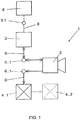
- Fig. 1 schematically shows a camera system 1 for a vehicle (not shown) according to a first embodiment.
- the camera system 1 has a control unit 2, an image recording unit 3, a first functional unit 4.1 and an image display unit 8.
- the control unit 2 serves to output and / or receive control signals and video signals and can be, for example, a board computer or an ECU (electronic control unit).
- the control unit 2 can be provided as a separate system component, but can also be provided in the housing of the image recording unit 3 or the image display unit 8.
- the image capturing unit 3 serves to capture images around a vehicle and / or inside a vehicle and can be a camera, such as a digital camera with a CCD technology or a CMOS technology or any other high-resolution camera.
- the first functional unit 4.1 generally provides additional functions for the image recording unit, the vehicle and / or the driver and can be any conceivable unit of a vehicle that is assigned a function that differs from the function of the image recording unit, such as various sensors and various signal lights , such as a turn signal or a reversing light, or an illumination of the image recording unit, such as an infrared (IR) light.
- the image display unit 8 can be a display device such as a display or a monitor, such as an LCD, TFT or LED monitor.
- a recording interface 5.1 is arranged between the image recording unit 3 and the control unit 2.
- the recording interface 5.1 can be provided on the image recording unit 3 and / or the control unit 2.
- the recording interface 5.1 is designed such that it transmits signals 5 from the control unit 2 to the image recording unit 3 and transmits signals 5 from the image recording unit 3 to the control unit 2. It is thus possible to transmit signals 5 in both directions between the control unit 2 and the image recording unit 3 using the recording interface 5.1.
- the signals 5 transmitted by the recording interface 5.1 can be control signals and / or video signals.
- Control signals can be signals for controlling the image recording unit 3, such as a signal for switching the image recording unit on / off when the engine of the vehicle is started / stopped, or a signal for setting a specific recording range of the image recording unit 3, such as when cornering, for example a blinking process is announced.
- Video signals can be signals for transmitting images which are recorded by the image recording unit 3.
- a video signal is a serial arrangement of electrical voltages through which image signals (image brightness and color), blanking pulses and synchronizing signals are transmitted.
- the image data transmitted via the video signals is processed by means of a processor, such as a CPU (central processing unit) or a microprocessor (not shown), which is usually arranged in the control unit.
- a display interface 9.1 is arranged between the image acquisition unit 3 and the image display unit 8.
- the playback interface 9.1 can on the image acquisition unit 3 and / or the image display unit 8 can be provided.
- the playback interface 9.1 is designed such that it transmits signals 9 from the control unit 2 to the playback unit 8 and preferably also transmits signals 9 from the playback unit 8 to the control unit 2. It is thus possible, using the playback interface 9.1, to transmit signals 9 between the control unit 2 and the playback unit 8, preferably in both directions.
- the signals 9 transmitted by the playback interface 9.1 can be control signals and / or video signals.
- Control signals can be signals for controlling the playback unit 8, such as switching the playback unit 8 on / off or setting a specific display area of the playback unit 8.
- Video signals can be signals for displaying the image data recorded by the image recording unit 3 and processed by the processor.
- a functional interface 6.1 is arranged between the image acquisition unit 3 and the functional unit 4.1.
- the functional interface 6.1 can be provided on the image acquisition unit 3 and / or the functional unit 4.1.
- the functional interface 6.1 is designed such that it transmits signals 6 from the image acquisition unit 3 to the functional unit 4.1.
- the signals 6 transmitted by the function interface 6.1 can be signals of the control unit 2, which are used to control the image acquisition unit 3 and the function unit 4.1.
- the control unit 2 outputs at least one control signal which is transmitted via the recording interface 5.1 to the image recording unit 3 for controlling the image recording unit 3.
- the signal output by the control unit 3 is transmitted or forwarded via the function interface 6.1 from the image acquisition unit 3 to the function unit 4.1 for controlling the function unit 6.1.
- control the functional unit 4.1 it may be necessary for the control signal transmitted to the functional unit 4.1 to be processed or converted in the image recording unit 3 by means of a processor (not shown). However, it is also possible for the image recording unit 3 and the functional unit 4.1 to be controlled via the same control signal.
- the functional unit 4.1 is thus controlled by a signal which passes through the image recording unit 3 and is thus transmitted from the image recording unit 3 to the functional unit 4.1.
- FIG. 1 Another functional unit 4.2 is shown, which is shown with dashed lines.
- the signal of the control unit 2, via which the functional unit 4.1 is controlled, can also be used to control the further functional unit 4.2.
- To control the further functional unit 4.2 it may be necessary for the functional unit 4.2 transmitted control signal is processed or converted in the functional unit 4.1 by means of a processor (not shown).
- the functional units 4.1, 4.2 are units or system components that do not perform a camera function, that is to say no image recording.
- the functional units 4.1, 4.2 rather provide additional functions for the image recording unit 3 and / or the vehicle and / or the driver.
- the additional functions of the functional units 4.1, 4.2 can be lighting (visible or infrared (IR) illumination) for the image recording unit 3 for illuminating the recording area of the image recording unit 3, cleaning the optics of the image recording unit 3 for ensuring optimal image recordings, additional heating for the Image acquisition unit 3 for preventing / eliminating the formation of condensation in the image acquisition unit 3 or a protective device, such as a protective flap (shutter) for the optics of the image acquisition unit 3 for protection against damage by foreign bodies.
- the additional functions of the functional units 4.1, 4.2 can include a horn, lighting of the vehicle or a distance sensor of the vehicle.
- the interfaces i.e. the recording interface 5.1
- the function interfaces 6.1 and the playback interface 9.1 are to be understood as devices with which two subsystems can be mechanically and signal-technically coupled, e.g. Plug and associated socket with the corresponding slots and / or poles.
- the functional unit 4.1 is a light sensor of the image recording unit 3 and the functional unit 4.2 is an IR illumination of the image recording unit 3.
- the task of the light sensor 4.1 is to detect the amount of light in the recording area of the image recording unit 3 and, in the event of a falling below a predetermined limit value for an illuminance (measured in the SI unit Lux), a signal for switching on lighting, namely IR illumination of the image recording unit 3 output.
- the control unit 2 outputs a control signal for switching on the image recording unit 3 when the engine of the vehicle is started, this control signal is also used to control the light sensor 4.1, possibly after processing by a processor in the image recording unit 3.
- the light sensor 4.1 determines that a quantity of light or illuminance is present in the recording area of the image recording unit 3, which is an illumination the image recording unit 3 requires, in order to be able to take suitable images of, for example, the surroundings of the vehicle, the light sensor 4.1. a signal that causes the IR lighting 4.2 to be switched on. In this way, a single control signal can be used to control both the image recording unit 3 and the functional units 4.1, 4.2. This enables a simple and at the same time compact construction of the camera system 1 according to the invention with reduced system costs, since cables or lines and control electronics modules are saved or reduced compared to conventional camera systems.
- the image acquisition unit 3 and the functional units 4.1, 4.2 are thus controlled via a vehicle bus, such as CAN, LIN, Ethernet or other bus systems and thus via a system for data transmission between several participants, here the control unit 2, the image acquisition unit 3, the first Functional unit 4.1 and the image display unit 8, via a common transmission path.
- the image recording unit 3 and the functional units 4.1, 4.2 are consequently designed such that they are coupled to one another. For example, this coupling can take place with regard to the function of the image recording unit 3 and the functional units 4.1, 4.2.
- At least the image recording unit 3 can also be operated without the functional units 4.1, 4.2. With reference to the above example, the image recording unit 3 can therefore continue to function even if the IR illumination and / or the light sensor are defective.
- the image recording unit 3 and the functional units 4.1, 4.2 can thus be decoupled from one another.
- FIG. 2 An exemplary second embodiment of a camera system 1 according to the invention is shown, which is not part of the claimed invention.
- the control unit 2 can also be integrated in the playback unit 8 (not shown). In this case, there is only the recording interface 5.1 between the image recording unit 3 and the image reproduction unit 8, which is suitable for transmitting both at least one video signal and at least one control signal.
- FIG. 3 A third embodiment of a camera system 1 according to the invention is shown.
- the function interface 4.1 is referred to as the first function interface 4.1.
- the signal transmission from the control unit 2 via the image acquisition unit 3 to the function interface 4.2 takes place in the same way as from the control unit 2 via the image acquisition unit 3 to the first function interface 4.1, which is described above with reference to the first embodiment.
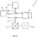
- FIG. 4 A fourth embodiment of a camera system 1 according to the invention is shown.
- the interface 5.1 is used to transmit and / or receive control signals to or from the control unit 2 and at the same time to transmit video signals from the image recording unit 3 to the image display unit 8.
- the transmission of control signals and video signals via separate interfaces.
- the in 1 to 4 have in common that they have at least one first functional interface 6.1, which is suitable for transmitting a control signal 6 from the image recording unit 3 to the first functional unit 4.1, and have at least one playback interface 9.1, which is suitable for transmitting a video signal 9 from the control unit 2 ( Fig. 1 and 3 ) or the image acquisition unit 3 ( Fig. 2 and 4 ) to be transmitted to the image display unit.
- Recording interface 5.1 shown is suitable for transmitting signals in both directions, namely at least one video signal from the image recording unit 3 to the control unit 2 and at least one control signal from the control unit 2 to the image recording unit 3.
- the interfaces 9.1 and 6.1, 7.1 are suitable for transmitting signals in both directions.
- Video signals are transmitted in Fig. 1 and 3 from the control unit 2 to the image display unit 8 and in Fig. 2 and 4 from the image recording unit 3 to the image display unit 8.
- the image display unit can be designed such that it outputs video signals and / or other signals to the control unit 2 or the image recording unit 3.
- any number of functional units 4.1, 4.2 ... 4.n can be integrated and retrofitted in the camera systems 1 according to the invention.
- the interfaces 5.1, 6.1 and 9.1 can be plug connections.
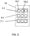
- Fig. 5 an example of a connector 10 of the interfaces 5.1, 6.1 and 7.1 is shown.
- the connector 10 shown has nine slots 10.1, 10.2, ... 10.9 (only slots 10.1, 10.2 numbered).
- the plugs of the various system units that is, the control unit 2, the receiving unit 3 and / or the functional unit 4.1, 4.2, can be inserted into the slots 10.1, 10.2, ... 10.9, with three slots being arranged in a row and the Has plug connection corresponding to three rows, each with three slots.
- the first row of the plug connection (which in Fig.
- two slots are provided for the group of video signals that are transmitted via the recording interface 5.1.
- the slots for transmission of the video signals can be side by side, optionally on the left (as in Fig. 5 shown) or on the right or also separately from each other.
- the slot remaining in the first row is in Fig. 5 along with that in the second row (middle row of slots in Fig. 5 ) for the transmission of signals that are transmitted via the first function interface 6.1.
- In the third row bottom row of slots in Fig. 5 ) only slots are provided for the transmission of signals that are transmitted via the second function interface 7.1. If not in Fig.
- the plug-in connection can also have further slots or further rows of slots for, for example, the playback interface 9.1 for the transmission of signals to and / or from the image display unit 8 and / or for further functional units 4.3, 4.4, ... 4.n.
- the interfaces 5.1, 6.1, 7.1, 9.1 can, as in Fig. 5 shown, be provided in a common connector 10. However, it is also conceivable to provide only the functional interface 6.1 and the recording interface 5.1 or the functional interface 6.1 and the playback interface 9.1 or the recording interface 5.1 or the playback interface 9.1 in a common plug connection and to provide the respective remaining interface in a plug connection which is separate from the common plug connection. Alternatively, each of the interfaces 5.1, 6.1, 7.1, 9.1 can also be provided as a separate plug connection. Also, more or fewer than nine slots can be provided in a connector.
- the interfaces 5.1, 6.1, 7.1, 9.1 are designed such that they are protected against the ingress of water, moisture and dirt, such as dust, by means of an appropriate sealing device, which improves the reliability of the interfaces 5.1, 6.1, 7.1, 9.1 and their Lifetime improved. Furthermore, the interfaces 5.1, 6.1, 7.1, 9.1 are electrically compatible, for example via the pin assignment and / or the type of signal (in terms of signal technology), and / or mechanically, for example via the connector geometry. For example, all interfaces of at least one type, that is, at least all function interfaces 6.1, at least all playback interfaces 9.1 or at least all recording interfaces 5.1, can be electrically and / or signal-technically and / or mechanically compatible.
- the individual interfaces 5.1, 6.1, 9.1 can also be electrically and / or signal-technically and / or mechanically compatible with one another in all conceivable combinations. This enables flexible use of the various plug-in connections, regardless of the structure of the camera system 1.
- the plug-in connection 10 as a whole and / or the individual plug-in locations 10.1, 10.2, inserted cables is prevented.
Landscapes
- Engineering & Computer Science (AREA)
- Multimedia (AREA)
- Mechanical Engineering (AREA)
- Signal Processing (AREA)
- Automation & Control Theory (AREA)
- Studio Devices (AREA)
- Closed-Circuit Television Systems (AREA)
Priority Applications (1)
| Application Number | Priority Date | Filing Date | Title |
|---|---|---|---|
| PL17204829T PL3335937T3 (pl) | 2016-12-16 | 2017-12-01 | System kamer oraz system zastępujący lusterka |
Applications Claiming Priority (1)
| Application Number | Priority Date | Filing Date | Title |
|---|---|---|---|
| DE102016124691.3A DE102016124691B4 (de) | 2016-12-16 | 2016-12-16 | Kamerasystem und Spiegelersatzsystem |
Publications (2)
| Publication Number | Publication Date |
|---|---|
| EP3335937A1 EP3335937A1 (de) | 2018-06-20 |
| EP3335937B1 true EP3335937B1 (de) | 2020-01-15 |
Family
ID=60543432
Family Applications (1)
| Application Number | Title | Priority Date | Filing Date |
|---|---|---|---|
| EP17204829.0A Active EP3335937B1 (de) | 2016-12-16 | 2017-12-01 | Kamerasystem und spiegelersatzsystem |
Country Status (7)
| Country | Link |
|---|---|
| US (1) | US11072281B2 (pl) |
| EP (1) | EP3335937B1 (pl) |
| KR (1) | KR102045252B1 (pl) |
| CN (1) | CN108297791B (pl) |
| DE (1) | DE102016124691B4 (pl) |
| ES (1) | ES2778452T3 (pl) |
| PL (1) | PL3335937T3 (pl) |
Families Citing this family (2)
| Publication number | Priority date | Publication date | Assignee | Title |
|---|---|---|---|---|
| DE102022113548A1 (de) | 2022-05-30 | 2023-11-30 | Zf Cv Systems Global Gmbh | Kameraanordnung, Fahrzeug, Fahrzeugverbund |
| DE102024125032A1 (de) * | 2024-09-02 | 2026-03-05 | Bayerische Motoren Werke Aktiengesellschaft | Steuergerät für ein kamera-monitor-system eines kraftfahrzeuges |
Family Cites Families (8)
| Publication number | Priority date | Publication date | Assignee | Title |
|---|---|---|---|---|
| WO2004082261A1 (en) * | 2003-03-11 | 2004-09-23 | Philips Intellectual Property & Standards Gmbh | Intelligent network interface module |
| US20040201703A1 (en) | 2003-04-14 | 2004-10-14 | Tai-Her Yang | Combined or standalone hand-held A/V camera system |
| WO2014009945A1 (en) * | 2012-07-09 | 2014-01-16 | Brightway Vision Ltd. | Stereo gated imaging system and method |
| DE102013021818A1 (de) * | 2013-12-21 | 2015-06-25 | Connaught Electronics Ltd. | Nach dem Baukastenprinzip aufgebaute Fahrzeugkamera und Kraftfahrzeug mit einer solchen Kamera |
| US10128595B2 (en) * | 2015-03-09 | 2018-11-13 | Magna Electronics Inc. | Vehicle camera with connector system for high speed transmission |
| CN204836400U (zh) * | 2015-07-21 | 2015-12-02 | 中国科学院西安光学精密机械研究所 | 一种嵌入式多功能的视频接口模块 |
| CN205790815U (zh) * | 2016-06-21 | 2016-12-07 | 深圳市爱迪芯科技有限公司 | 一种集hub、视频、移动电源于一体的hub |
| CN205754540U (zh) * | 2016-06-25 | 2016-11-30 | 黑龙江广播电视台 | 一种除尘、四进线口的超薄封闭式多功能接口箱 |
-
2016
- 2016-12-16 DE DE102016124691.3A patent/DE102016124691B4/de not_active Expired - Fee Related
-
2017
- 2017-12-01 PL PL17204829T patent/PL3335937T3/pl unknown
- 2017-12-01 ES ES17204829T patent/ES2778452T3/es active Active
- 2017-12-01 EP EP17204829.0A patent/EP3335937B1/de active Active
- 2017-12-14 CN CN201711338696.9A patent/CN108297791B/zh active Active
- 2017-12-15 US US15/843,962 patent/US11072281B2/en active Active
- 2017-12-18 KR KR1020170174323A patent/KR102045252B1/ko active Active
Non-Patent Citations (1)
| Title |
|---|
| None * |
Also Published As
| Publication number | Publication date |
|---|---|
| KR102045252B1 (ko) | 2019-11-15 |
| KR20180070500A (ko) | 2018-06-26 |
| US20180170260A1 (en) | 2018-06-21 |
| EP3335937A1 (de) | 2018-06-20 |
| CN108297791B (zh) | 2021-05-14 |
| DE102016124691A1 (de) | 2018-06-21 |
| CN108297791A (zh) | 2018-07-20 |
| US11072281B2 (en) | 2021-07-27 |
| ES2778452T3 (es) | 2020-08-10 |
| DE102016124691B4 (de) | 2024-03-28 |
| PL3335937T3 (pl) | 2020-06-29 |
Similar Documents
| Publication | Publication Date | Title |
|---|---|---|
| EP2431226B1 (de) | Rückblickeinrichtung für ein Kraftfahrzeug | |
| EP1018839B1 (de) | Verfahren und Einrichtung zur Einsichtnahme des rückwärtigen Beobachtungsraumes bei Kraftfahrzeugen | |
| DE102012015398B3 (de) | Spiegelersatzsystem für ein Fahrzeug | |
| DE69420360T2 (de) | Abgeschlossenes Multikamerafernsehsystem für Flugzeuge | |
| DE10132982B4 (de) | Einrichtung zum Erfassen optischer Informationen | |
| DE102015216285A1 (de) | Elektronische Steuereinheit und fahrzeuginternes Videosystem | |
| DE102010032411A1 (de) | Vorrichtung zur Überwachung der seitlichen und rückwärtigen Umgebung eines Fahrzeugs | |
| DE102011077398B4 (de) | Fahrzeugkamerasystem zur Bereitstellung eines lückenlosen Bildes der Fahrzeugumgebung und entsprechendes Verfahren | |
| DE102006007493A1 (de) | Vorrichtung zum Sehen der Peripherie eines Fahrzeuges | |
| EP1339228B1 (de) | Verfahren und Vorrichtung zur Sichtbarmachung eines Ausschnitts der Umgebung eines Fahrzeugs sowie eine Kalibriereinheit zur Kalibrierung der Vorrichtung | |
| DE102019126814A1 (de) | Elektronische Steuereinheit | |
| EP3335937B1 (de) | Kamerasystem und spiegelersatzsystem | |
| DE112008002745T5 (de) | Fahrzeugumgebungsüberwachungssystem und Fahrzeugbasisbeleuchtungssystem | |
| WO2022037926A1 (de) | Kamera, a-säulen-anordnung und fahrzeug | |
| DE102018105657B3 (de) | Rückblicksensoranordnung und fahrzeug | |
| DE10218175B4 (de) | Verfahren und Vorrichtung zur Sichtbarmachung der Umgebung eines Fahrzeugs mit fahrsituationsabhängiger Fusion eines Infrarot- und eines Visuell-Abbilds | |
| DE102022120236B3 (de) | Verfahren zum harmonisierten Anzeigen von Kamerabildern in einem Kraftfahrzeug und entsprechend eingerichtetes Kraftfahrzeug | |
| DE10321228A1 (de) | Optisches Erfassungssystem für Fahrzeuge | |
| DE102022107023B4 (de) | Rückblickkameraanordnung | |
| DE102016221791A1 (de) | Spiegelersatzsystem sowie Verfahren zum Betrieb eines Spiegelersatzsystems für ein Fahrzeug | |
| DE112015002456B4 (de) | Außenspiegelersatzsystem für eine Zugfahrzeug-Anhänger-Kombination und zugehöriges Verfahren | |
| DE102018201852B4 (de) | Bildschirmvorrichtung mit steuerbarem Zusatz-Leuchtelement | |
| DE102022123561A1 (de) | Frontkamerasystem für ein Fahrzeug | |
| DE102022113653A1 (de) | Beleuchtungsanordnung mit einem Steuergerät, mit einem Beleuchtungsmodul und mit einem Peripheriemodul | |
| EP1922871B1 (de) | Übertragung von nutzdaten im bildsignal eines kamerasystems |
Legal Events
| Date | Code | Title | Description |
|---|---|---|---|
| PUAI | Public reference made under article 153(3) epc to a published international application that has entered the european phase |
Free format text: ORIGINAL CODE: 0009012 |
|
| STAA | Information on the status of an ep patent application or granted ep patent |
Free format text: STATUS: REQUEST FOR EXAMINATION WAS MADE |
|
| 17P | Request for examination filed |
Effective date: 20171201 |
|
| AK | Designated contracting states |
Kind code of ref document: A1 Designated state(s): AL AT BE BG CH CY CZ DE DK EE ES FI FR GB GR HR HU IE IS IT LI LT LU LV MC MK MT NL NO PL PT RO RS SE SI SK SM TR |
|
| AX | Request for extension of the european patent |
Extension state: BA ME |
|
| STAA | Information on the status of an ep patent application or granted ep patent |
Free format text: STATUS: EXAMINATION IS IN PROGRESS |
|
| 17Q | First examination report despatched |
Effective date: 20190220 |
|
| GRAP | Despatch of communication of intention to grant a patent |
Free format text: ORIGINAL CODE: EPIDOSNIGR1 |
|
| STAA | Information on the status of an ep patent application or granted ep patent |
Free format text: STATUS: GRANT OF PATENT IS INTENDED |
|
| INTG | Intention to grant announced |
Effective date: 20190923 |
|
| GRAS | Grant fee paid |
Free format text: ORIGINAL CODE: EPIDOSNIGR3 |
|
| GRAA | (expected) grant |
Free format text: ORIGINAL CODE: 0009210 |
|
| STAA | Information on the status of an ep patent application or granted ep patent |
Free format text: STATUS: THE PATENT HAS BEEN GRANTED |
|
| AK | Designated contracting states |
Kind code of ref document: B1 Designated state(s): AL AT BE BG CH CY CZ DE DK EE ES FI FR GB GR HR HU IE IS IT LI LT LU LV MC MK MT NL NO PL PT RO RS SE SI SK SM TR |
|
| REG | Reference to a national code |
Ref country code: GB Ref legal event code: FG4D Free format text: NOT ENGLISH Ref country code: CH Ref legal event code: EP |
|
| REG | Reference to a national code |
Ref country code: IE Ref legal event code: FG4D Free format text: LANGUAGE OF EP DOCUMENT: GERMAN |
|
| REG | Reference to a national code |
Ref country code: DE Ref legal event code: R096 Ref document number: 502017003510 Country of ref document: DE |
|
| REG | Reference to a national code |
Ref country code: AT Ref legal event code: REF Ref document number: 1224891 Country of ref document: AT Kind code of ref document: T Effective date: 20200215 |
|
| REG | Reference to a national code |
Ref country code: NL Ref legal event code: FP |
|
| REG | Reference to a national code |
Ref country code: SE Ref legal event code: TRGR |
|
| REG | Reference to a national code |
Ref country code: LT Ref legal event code: MG4D |
|
| PG25 | Lapsed in a contracting state [announced via postgrant information from national office to epo] |
Ref country code: RS Free format text: LAPSE BECAUSE OF FAILURE TO SUBMIT A TRANSLATION OF THE DESCRIPTION OR TO PAY THE FEE WITHIN THE PRESCRIBED TIME-LIMIT Effective date: 20200115 Ref country code: FI Free format text: LAPSE BECAUSE OF FAILURE TO SUBMIT A TRANSLATION OF THE DESCRIPTION OR TO PAY THE FEE WITHIN THE PRESCRIBED TIME-LIMIT Effective date: 20200115 Ref country code: NO Free format text: LAPSE BECAUSE OF FAILURE TO SUBMIT A TRANSLATION OF THE DESCRIPTION OR TO PAY THE FEE WITHIN THE PRESCRIBED TIME-LIMIT Effective date: 20200415 Ref country code: PT Free format text: LAPSE BECAUSE OF FAILURE TO SUBMIT A TRANSLATION OF THE DESCRIPTION OR TO PAY THE FEE WITHIN THE PRESCRIBED TIME-LIMIT Effective date: 20200607 |
|
| REG | Reference to a national code |
Ref country code: ES Ref legal event code: FG2A Ref document number: 2778452 Country of ref document: ES Kind code of ref document: T3 Effective date: 20200810 |
|
| PG25 | Lapsed in a contracting state [announced via postgrant information from national office to epo] |
Ref country code: IS Free format text: LAPSE BECAUSE OF FAILURE TO SUBMIT A TRANSLATION OF THE DESCRIPTION OR TO PAY THE FEE WITHIN THE PRESCRIBED TIME-LIMIT Effective date: 20200515 Ref country code: LV Free format text: LAPSE BECAUSE OF FAILURE TO SUBMIT A TRANSLATION OF THE DESCRIPTION OR TO PAY THE FEE WITHIN THE PRESCRIBED TIME-LIMIT Effective date: 20200115 Ref country code: BG Free format text: LAPSE BECAUSE OF FAILURE TO SUBMIT A TRANSLATION OF THE DESCRIPTION OR TO PAY THE FEE WITHIN THE PRESCRIBED TIME-LIMIT Effective date: 20200415 Ref country code: HR Free format text: LAPSE BECAUSE OF FAILURE TO SUBMIT A TRANSLATION OF THE DESCRIPTION OR TO PAY THE FEE WITHIN THE PRESCRIBED TIME-LIMIT Effective date: 20200115 Ref country code: GR Free format text: LAPSE BECAUSE OF FAILURE TO SUBMIT A TRANSLATION OF THE DESCRIPTION OR TO PAY THE FEE WITHIN THE PRESCRIBED TIME-LIMIT Effective date: 20200416 |
|
| REG | Reference to a national code |
Ref country code: DE Ref legal event code: R097 Ref document number: 502017003510 Country of ref document: DE |
|
| PG25 | Lapsed in a contracting state [announced via postgrant information from national office to epo] |
Ref country code: SK Free format text: LAPSE BECAUSE OF FAILURE TO SUBMIT A TRANSLATION OF THE DESCRIPTION OR TO PAY THE FEE WITHIN THE PRESCRIBED TIME-LIMIT Effective date: 20200115 Ref country code: DK Free format text: LAPSE BECAUSE OF FAILURE TO SUBMIT A TRANSLATION OF THE DESCRIPTION OR TO PAY THE FEE WITHIN THE PRESCRIBED TIME-LIMIT Effective date: 20200115 Ref country code: LT Free format text: LAPSE BECAUSE OF FAILURE TO SUBMIT A TRANSLATION OF THE DESCRIPTION OR TO PAY THE FEE WITHIN THE PRESCRIBED TIME-LIMIT Effective date: 20200115 Ref country code: EE Free format text: LAPSE BECAUSE OF FAILURE TO SUBMIT A TRANSLATION OF THE DESCRIPTION OR TO PAY THE FEE WITHIN THE PRESCRIBED TIME-LIMIT Effective date: 20200115 Ref country code: SM Free format text: LAPSE BECAUSE OF FAILURE TO SUBMIT A TRANSLATION OF THE DESCRIPTION OR TO PAY THE FEE WITHIN THE PRESCRIBED TIME-LIMIT Effective date: 20200115 Ref country code: CZ Free format text: LAPSE BECAUSE OF FAILURE TO SUBMIT A TRANSLATION OF THE DESCRIPTION OR TO PAY THE FEE WITHIN THE PRESCRIBED TIME-LIMIT Effective date: 20200115 Ref country code: RO Free format text: LAPSE BECAUSE OF FAILURE TO SUBMIT A TRANSLATION OF THE DESCRIPTION OR TO PAY THE FEE WITHIN THE PRESCRIBED TIME-LIMIT Effective date: 20200115 |
|
| PLBE | No opposition filed within time limit |
Free format text: ORIGINAL CODE: 0009261 |
|
| STAA | Information on the status of an ep patent application or granted ep patent |
Free format text: STATUS: NO OPPOSITION FILED WITHIN TIME LIMIT |
|
| 26N | No opposition filed |
Effective date: 20201016 |
|
| PG25 | Lapsed in a contracting state [announced via postgrant information from national office to epo] |
Ref country code: SI Free format text: LAPSE BECAUSE OF FAILURE TO SUBMIT A TRANSLATION OF THE DESCRIPTION OR TO PAY THE FEE WITHIN THE PRESCRIBED TIME-LIMIT Effective date: 20200115 |
|
| REG | Reference to a national code |
Ref country code: CH Ref legal event code: PL |
|
| PG25 | Lapsed in a contracting state [announced via postgrant information from national office to epo] |
Ref country code: MC Free format text: LAPSE BECAUSE OF FAILURE TO SUBMIT A TRANSLATION OF THE DESCRIPTION OR TO PAY THE FEE WITHIN THE PRESCRIBED TIME-LIMIT Effective date: 20200115 |
|
| REG | Reference to a national code |
Ref country code: BE Ref legal event code: MM Effective date: 20201231 |
|
| PG25 | Lapsed in a contracting state [announced via postgrant information from national office to epo] |
Ref country code: LU Free format text: LAPSE BECAUSE OF NON-PAYMENT OF DUE FEES Effective date: 20201201 Ref country code: IE Free format text: LAPSE BECAUSE OF NON-PAYMENT OF DUE FEES Effective date: 20201201 |
|
| PG25 | Lapsed in a contracting state [announced via postgrant information from national office to epo] |
Ref country code: CH Free format text: LAPSE BECAUSE OF NON-PAYMENT OF DUE FEES Effective date: 20201231 Ref country code: LI Free format text: LAPSE BECAUSE OF NON-PAYMENT OF DUE FEES Effective date: 20201231 |
|
| PG25 | Lapsed in a contracting state [announced via postgrant information from national office to epo] |
Ref country code: MT Free format text: LAPSE BECAUSE OF FAILURE TO SUBMIT A TRANSLATION OF THE DESCRIPTION OR TO PAY THE FEE WITHIN THE PRESCRIBED TIME-LIMIT Effective date: 20200115 Ref country code: CY Free format text: LAPSE BECAUSE OF FAILURE TO SUBMIT A TRANSLATION OF THE DESCRIPTION OR TO PAY THE FEE WITHIN THE PRESCRIBED TIME-LIMIT Effective date: 20200115 |
|
| PG25 | Lapsed in a contracting state [announced via postgrant information from national office to epo] |
Ref country code: MK Free format text: LAPSE BECAUSE OF FAILURE TO SUBMIT A TRANSLATION OF THE DESCRIPTION OR TO PAY THE FEE WITHIN THE PRESCRIBED TIME-LIMIT Effective date: 20200115 Ref country code: AL Free format text: LAPSE BECAUSE OF FAILURE TO SUBMIT A TRANSLATION OF THE DESCRIPTION OR TO PAY THE FEE WITHIN THE PRESCRIBED TIME-LIMIT Effective date: 20200115 |
|
| PG25 | Lapsed in a contracting state [announced via postgrant information from national office to epo] |
Ref country code: BE Free format text: LAPSE BECAUSE OF NON-PAYMENT OF DUE FEES Effective date: 20201231 |
|
| P01 | Opt-out of the competence of the unified patent court (upc) registered |
Effective date: 20230427 |
|
| REG | Reference to a national code |
Ref country code: DE Ref legal event code: R082 Ref document number: 502017003510 Country of ref document: DE Representative=s name: ALPSPITZ IP ALLGAYER UND PARTNER PATENTANWAELT, DE |
|
| REG | Reference to a national code |
Ref country code: AT Ref legal event code: MM01 Ref document number: 1224891 Country of ref document: AT Kind code of ref document: T Effective date: 20221201 |
|
| PG25 | Lapsed in a contracting state [announced via postgrant information from national office to epo] |
Ref country code: AT Free format text: LAPSE BECAUSE OF NON-PAYMENT OF DUE FEES Effective date: 20221201 |
|
| PG25 | Lapsed in a contracting state [announced via postgrant information from national office to epo] |
Ref country code: AT Free format text: LAPSE BECAUSE OF NON-PAYMENT OF DUE FEES Effective date: 20221201 |
|
| PGFP | Annual fee paid to national office [announced via postgrant information from national office to epo] |
Ref country code: GB Payment date: 20251218 Year of fee payment: 9 |
|
| PGFP | Annual fee paid to national office [announced via postgrant information from national office to epo] |
Ref country code: FR Payment date: 20251217 Year of fee payment: 9 Ref country code: NL Payment date: 20251217 Year of fee payment: 9 |
|
| PGFP | Annual fee paid to national office [announced via postgrant information from national office to epo] |
Ref country code: TR Payment date: 20251206 Year of fee payment: 9 |
|
| PGFP | Annual fee paid to national office [announced via postgrant information from national office to epo] |
Ref country code: SE Payment date: 20251217 Year of fee payment: 9 |
|
| PGFP | Annual fee paid to national office [announced via postgrant information from national office to epo] |
Ref country code: PL Payment date: 20251119 Year of fee payment: 9 |
|
| PGFP | Annual fee paid to national office [announced via postgrant information from national office to epo] |
Ref country code: ES Payment date: 20260119 Year of fee payment: 9 |
|
| PGFP | Annual fee paid to national office [announced via postgrant information from national office to epo] |
Ref country code: DE Payment date: 20251222 Year of fee payment: 9 |
|
| PGFP | Annual fee paid to national office [announced via postgrant information from national office to epo] |
Ref country code: AT Payment date: 20260410 Year of fee payment: 5 |
|
| PGFP | Annual fee paid to national office [announced via postgrant information from national office to epo] |
Ref country code: IT Payment date: 20251231 Year of fee payment: 9 |