EP3335754A1 - Endotracheale intubationsvorrichtung - Google Patents
Endotracheale intubationsvorrichtung Download PDFInfo
- Publication number
- EP3335754A1 EP3335754A1 EP16204087.7A EP16204087A EP3335754A1 EP 3335754 A1 EP3335754 A1 EP 3335754A1 EP 16204087 A EP16204087 A EP 16204087A EP 3335754 A1 EP3335754 A1 EP 3335754A1
- Authority
- EP
- European Patent Office
- Prior art keywords
- string
- actuator
- opposite
- stylet
- distal
- Prior art date
- Legal status (The legal status is an assumption and is not a legal conclusion. Google has not performed a legal analysis and makes no representation as to the accuracy of the status listed.)
- Withdrawn
Links
Images


Classifications
-
- A—HUMAN NECESSITIES
- A61—MEDICAL OR VETERINARY SCIENCE; HYGIENE
- A61M—DEVICES FOR INTRODUCING MEDIA INTO, OR ONTO, THE BODY; DEVICES FOR TRANSDUCING BODY MEDIA OR FOR TAKING MEDIA FROM THE BODY; DEVICES FOR PRODUCING OR ENDING SLEEP OR STUPOR
- A61M16/00—Devices for influencing the respiratory system of patients by gas treatment, e.g. mouth-to-mouth respiration; Tracheal tubes
- A61M16/04—Tracheal tubes
- A61M16/0488—Mouthpieces; Means for guiding, securing or introducing the tubes
-
- A—HUMAN NECESSITIES
- A61—MEDICAL OR VETERINARY SCIENCE; HYGIENE
- A61B—DIAGNOSIS; SURGERY; IDENTIFICATION
- A61B1/00—Instruments for performing medical examinations of the interior of cavities or tubes of the body by visual or photographical inspection, e.g. endoscopes; Illuminating arrangements therefor
- A61B1/005—Flexible endoscopes
- A61B1/0051—Flexible endoscopes with controlled bending of insertion part
-
- A—HUMAN NECESSITIES
- A61—MEDICAL OR VETERINARY SCIENCE; HYGIENE
- A61B—DIAGNOSIS; SURGERY; IDENTIFICATION
- A61B1/00—Instruments for performing medical examinations of the interior of cavities or tubes of the body by visual or photographical inspection, e.g. endoscopes; Illuminating arrangements therefor
- A61B1/267—Instruments for performing medical examinations of the interior of cavities or tubes of the body by visual or photographical inspection, e.g. endoscopes; Illuminating arrangements therefor for the respiratory tract, e.g. laryngoscopes, bronchoscopes
-
- A—HUMAN NECESSITIES
- A61—MEDICAL OR VETERINARY SCIENCE; HYGIENE
- A61M—DEVICES FOR INTRODUCING MEDIA INTO, OR ONTO, THE BODY; DEVICES FOR TRANSDUCING BODY MEDIA OR FOR TAKING MEDIA FROM THE BODY; DEVICES FOR PRODUCING OR ENDING SLEEP OR STUPOR
- A61M25/00—Catheters; Hollow probes
- A61M25/01—Introducing, guiding, advancing, emplacing or holding catheters
- A61M25/0105—Steering means as part of the catheter or advancing means; Markers for positioning
- A61M25/0133—Tip steering devices
-
- A—HUMAN NECESSITIES
- A61—MEDICAL OR VETERINARY SCIENCE; HYGIENE
- A61M—DEVICES FOR INTRODUCING MEDIA INTO, OR ONTO, THE BODY; DEVICES FOR TRANSDUCING BODY MEDIA OR FOR TAKING MEDIA FROM THE BODY; DEVICES FOR PRODUCING OR ENDING SLEEP OR STUPOR
- A61M16/00—Devices for influencing the respiratory system of patients by gas treatment, e.g. mouth-to-mouth respiration; Tracheal tubes
- A61M16/04—Tracheal tubes
- A61M16/0402—Special features for tracheal tubes not otherwise provided for
- A61M16/0418—Special features for tracheal tubes not otherwise provided for with integrated means for changing the degree of curvature, e.g. for easy intubation
-
- A—HUMAN NECESSITIES
- A61—MEDICAL OR VETERINARY SCIENCE; HYGIENE
- A61M—DEVICES FOR INTRODUCING MEDIA INTO, OR ONTO, THE BODY; DEVICES FOR TRANSDUCING BODY MEDIA OR FOR TAKING MEDIA FROM THE BODY; DEVICES FOR PRODUCING OR ENDING SLEEP OR STUPOR
- A61M25/00—Catheters; Hollow probes
- A61M25/01—Introducing, guiding, advancing, emplacing or holding catheters
- A61M25/0105—Steering means as part of the catheter or advancing means; Markers for positioning
- A61M25/0133—Tip steering devices
- A61M25/0147—Tip steering devices with movable mechanical means, e.g. pull wires
- A61M2025/015—Details of the distal fixation of the movable mechanical means
-
- A—HUMAN NECESSITIES
- A61—MEDICAL OR VETERINARY SCIENCE; HYGIENE
- A61M—DEVICES FOR INTRODUCING MEDIA INTO, OR ONTO, THE BODY; DEVICES FOR TRANSDUCING BODY MEDIA OR FOR TAKING MEDIA FROM THE BODY; DEVICES FOR PRODUCING OR ENDING SLEEP OR STUPOR
- A61M25/00—Catheters; Hollow probes
- A61M25/01—Introducing, guiding, advancing, emplacing or holding catheters
- A61M25/0102—Insertion or introduction using an inner stiffening member, e.g. stylet or push-rod
-
- A—HUMAN NECESSITIES
- A61—MEDICAL OR VETERINARY SCIENCE; HYGIENE
- A61M—DEVICES FOR INTRODUCING MEDIA INTO, OR ONTO, THE BODY; DEVICES FOR TRANSDUCING BODY MEDIA OR FOR TAKING MEDIA FROM THE BODY; DEVICES FOR PRODUCING OR ENDING SLEEP OR STUPOR
- A61M25/00—Catheters; Hollow probes
- A61M25/01—Introducing, guiding, advancing, emplacing or holding catheters
- A61M25/0105—Steering means as part of the catheter or advancing means; Markers for positioning
- A61M25/0133—Tip steering devices
- A61M25/0136—Handles therefor
Definitions
- the present invention relates to an endotracheal device of the kind comprising a stylet part and a handle part for operating the stylet part, wherein the stylet part has a proximal stylet end and an opposite distal stylet end; the proximal stylet end is situated at the handle part, and the distal stylet end has an extension in form of a bendable tip part with a free end; a tip part operating member includes at least a first string member and a second string member arranged along the length of at least a length of the stylet part, and the handle part has an actuator means for operating at least the tip part operating member.
- the present invention relates to endotracheal intubation, and apparatuses and methods useful in the positioning of an endotracheal tube within the airways of a patient.
- Laryngoscopes are therefore often used to obtain a view of the glottis or the larynx, or to manipulate the tongue, glottis or larynx in order to facilitate insertion of such an endotracheal tube or other instruments such as endoscopes.
- endotracheal tubes can be difficult even for skilled physicians, particularly in patient's having anterior trachea and other conditions that make it challenging to guide the distal end of the endotracheal tube past the vocal cords and into the trachea.
- Video laryngoscopes are however today used with rigid stylets, e.g. the GlideScope® is used with the GlideRite® Rigid Stylet that has a preformed curvature. Other rigid stylets can be bend to a given preformed curvature but the tip has no individual maneuverability.
- a typical conventional stylet contains a single flexible wire with a PVC coating and a uni-directional end cap that prevents the stylet from moving forward during the intubation process to lower the risk of unnecessary trauma to the patient.
- the stylet is inserted into the endotracheal tube so that the tube connector engages the uni-directional end cap.
- US patent no. 6,539,942 discloses a tubular endotracheal device, capable of being flexed into a L-shape and through which a conventional imaging device, such as a nasopharyngoscope, is inserted centrally, so as to allow for direct visualization of the vocal cords
- US patent application no. 2013/255671 discloses an articulating stylet device having the ability to bend an endotracheal tube in more than one direction while the tube is being positioned in a patient's airway.
- This known articulating stylet device can bend the endotracheal tube in two directions, e.g. clockwise bend over a middle portion of the endotracheal tube and a counter-clockwise bend over a distal end portion of the endotracheal tube.
- This known articulating stylet is comprised of a plurality of beads arranged in sequential series. Each series is composed of differently configured beads having adjacent angled or beveled end surfaces.
- the beads have first and second longitudinal passageways for being threaded on a respective first and second metal wire, to make a stylet in form of a bendable "string of beads".
- One metal wire is secured to the free bead at the free distal end of the string of beads and the other metal wire is secured a distance from the first wire six beads proximal to the free distal bead.
- This different securing location of the first metal wire and the second metal wire makes the string of beads a separately articulating stylet device.
- This known stylet is given sufficient rigidity to keep elongate but bendable shape by keeping the beads intimately together on the metal wires, and has special tensioning means for that purpose.
- it is a challenge to arrange the bead correctly on the metal wires and a challenge to tension the wires correctly after all beads have been arranged as intended.
- a major disadvantage of this known stylet is that the beads inevitabley become slightly dislocated if tensioning of a wire is unsuccessful, or if the wire is too slack.
- the angled or beveled end surfaces of two adjacent beads need to be arranged in intimate contact to prevent jamming of the beads. If tensioning is lost the string of beads get too slack and cannot keep required dimensional shape to constitute a stylet for inserting a endotracheal tube, and if just a single bead becomes slightly offset or dislocated the string of bead cannot be bend as intended.
- a further huge disadvantage is that the gap between to adjacent beads may accidentally pinch and injure the endotracheal tube on the bead stylet, and dislocation of beads may increase stylet diameter and prevent its retraction from the endotracheal tube.
- proximal is used to indicate a position nearest to the handle part and the term “distal” is used to indicate a position nearest the bendable tip part.
- housing is used for a receptacle that is hollow to accommodate at least some of the mechanisms to operate the endotracheal device.
- the patient is first positioned so that the axial planes of the oral, pharyngeal and tracheal axes are aligned.
- the operator holds the laryngoscope, preferably a video laryngoscope, in his/her left hand.
- a cricoid pressure may be maintained, typically by another person assisting the operator, until the end of the procedure where the endotracheal tube is in correct place and the cuff has been inflated.
- the tip of the video laryngoscope is inserted into the right side of the patient's mouth and the blade is advanced to the base of the tongue, which is moved to the side, and the blade is moved forward.
- a straight blade is moved beneath the epiglottis and a curved blade is placed into the vallecula above the epiglottis keeping attention to keep the curved blade in midline and not applying traction along the axis of the laryngoscope handle as the laryngoscope lifts the tongue upwards away from the larynx to reveal the glottie opening and visualize the vocal cords.
- the endotraceal tube is then inserted through the vocal cords holding the stylet with the endotracheal tube with the right hand.
- An angled stylet may interfere with the passage of the endotracheal tube into the trachea and may cause difficult manipulation to pass through the vocal cords.
- the stylet is removed, optionally the position of the endotracheal tube is corrected, the laryngoscope is removed, the cuff is inflated and safe insertion confirmed, e.g. by monitoring or observing end-tidal CO 2 , listening using a stethoscope, observing condensation in the exterior length of the endotracheal tube, X-ray, etc.
- the skilled person knows these medical procedures.
- Known stylets for use in the above intubation procedures either has a predetermined curvature or is bendable to be curved into the overall desired shape rather than bending just the bendable tip part.
- two separate string members a first string member and a second string member, respectively, are secured at two different securing locations inside the bendable tip part to arbitrarily move the bendable tip part at least lengthwise.
- a string member of the tip part operating member is operated independent of the other string member of the tip part operating member, via the actuator means of the handle part, either by a string member being tensioned of by relaxing tensioning of a string member, the respective string-securing locations are moved in relation to the distal end of the elongate hollow guide member, thus where said elongate hollow guide member extends distally into the bendable tip part.
- the string members can be operated separately almost any imaginable shape of the distally arranged bendable tip part can be given to it simply by pulling the two string members more or less.
- One string member can be operated or both string members can be operated at the same time. Same or different levels of tensioning can be applied to the first string member and the second string member.
- the operator grasps around the handle part to operate the tip part operating member to almost arbitrarily move the first string member and/or the second string member lengthwise inside the elongate hollow guide member to bend the bendable tip part at the distal stylet end.
- the free end of the bendable tip part can e.g. be moved below or above the elongate hollow guide member, when seen in the operative orientation of the endotracheal device, be given an S-shaped, be given a C-shape, an L-shape, or combination of any of these shapes.
- the bendable tip part can also move to the side. Combinations of lateral offset and lengthwise offset first string-securing location and second string-securing location are within the scope of the present invention.
- the elongate hollow guide member and the bendable tip part safely sheath, guides and confine the first string member and the second string member so that the patient's tissue never can get in direct contact with any of the string members. Should the unimaginable accident occur that the first distal string end of the first string member disconnects from the first string-securing location and/or the second distal string end of the second string member disconnects from the second string-securing location such a detached end of a string member can never spring back to come in contact with patient's tissue and injure the patient. If the same happens for the beaded wire of the prior art stylet disclosed in US patent application no. 2013/255671 one or more beads could drop off the wire when the stylet is retracted from the endotracheal tube. Loose beads can in the best-case scenario be trapped inside the endotracheal tube in which case the procedure must be repeated, or worse, be trapped inside the airways, which could be fatal to the patient or require emergency surgery.
- the elongate hollow guide member is a curved pipe
- the bendable tip part includes a tubular cover that accommodates a tip-shaping member to which the first distal string end and the second distal string end are individually attached at respective first string-securing location and second string-securing location.
- the tip-shaping member is part of the tip part operating member.
- the elongate hollow guide member can have a curvature following a sector of a circle or have curved sections of different curvatures.
- the proximal end part of the elongate hollow guide member may be defined by a first sector of a circle having a large first radius.
- This proximal end part may extend via an intermediate part defined by a second sector of a circle having a second radius smaller than the first radius, which intermediate part then again may extend into the distal end part of the elongate hollow guide member, which distal end part can have a third radius smaller than the second radius.
- This design is just given as an example of a suitable curvature design of the elongate hollow guide member and variations are indeed feasible within the scope of the present invention.
- the preferred curvature of the elongate hollow guide member is the curvature of the endotracheal tube that conforms at least to some extent to the shape of the airway with the patient's head held in the neutral position, a curvature often referred to as the "the Magill Curve".
- "A Magill Curve” having a radius of curvature of 140 mm ⁇ 20 mm is found to be about optimum for the average airway, [ Tracheal intubation and sore throat: A mechanical explanation; M. Chandler; Anaesthesia 2002, 57, pages 155-161 ], and suited for the present invention, although various curvatures may work better for various target patients.
- the elongate hollow guide member can e.g. be made of aluminium or similar lightweight material.
- the tubular cover can e.g. be a soft plastic tube, e.g. of polyethylene or polyethylene vinyl chloride, but any material can be used provided that the tubular cover is able to yield and bend in response to bending of the tip-shaping member inside the tubular cover without any noticeable increase in the overall diameter of the bendable tip part by pulling the string members.
- the plastic tube is transparent the operator can even visually follow how the tip-shaping member reacts in response to the operator operating the actuator means thereby providing the operator with a huge advantage of learning and obtaining knowledge of the induced impact on the tip-shaping member in response to such operating of the actuator means, and thus learn how to manipulate the tip-shaping member to assume any desired shape of the bendable tip part. Transparency is however in no way mandatory and same experience of shaping the tip-shaping member can be obtained irrespective of transparency by testing the actuator means.
- the first string-securing location and the second string-securing location can be situated lengthwise offset to facilitate bending of the bendable tip part in a more or less distinct S-shape, L-shape or C-shape to assume a shape that can navigate the least obstructed into trachea and be made straight again when desired and needed for retracting the stylet part, e.g. retracting the stylet part from an endotracheal tube that was sheathed on the stylet part prior to the introduction of the endotracheal device into trachea and now is left as introduced for ventilation of the patient.
- Bending and relaxing the bendable tip part can take place both during inserting this tip part with or without an endotracheal tube sheathed on the stylet part as well as when the endotracheal device is retracted.
- the endotracheal device of the present invention is provided with the ability to arbitrarily control and customize the shape and curvature of the bendable tip part to a shape specific for the airway anatomy of a certain patient, which significantly eases the insertion of both the stylet part and an endotracheal tube sheathed on the stylet part.
- the bendable tip part can also be moved slightly from side to side.
- first string-securing location and the second string-securing location may be both radially/laterally and lengthwise offset so that both bending the bendable tip part lengthwise and moving a securing location slightly to the side are possible.
- the above-mentioned improved and very versatile in situ and real time ability to change the shape of the bendable tip part both outside and inside the patient's body provides an endotracheal device that is very fast and convenient to operate, insert correct, and retract without injuring or otherwise harming the patient.
- the string-securing locations can be moved into a plurality of different positions so that the shape of the bendable tip part can be adapted for use with even the most difficult airways thereby making the endotracheal device of the present invention not only user-friendly but also patient-friendly.
- the tip-shaping member may have a first end secured to the free end of the bendable tip part, and an opposite second end secured to or at the vicinity of the distal end of the elongate hollow guide member so that the tip-shaping member is kept from coiling inside its accommodation in the tubular cover of the bendable tip part, and so that when the first string location and the second string location is tensioned and/or relaxed the first end and the second end of the tip-shaping member are firmly attached at the respective securing points associated with the bendable tip part and/or the stylet part.
- the handle part incorporates the actuator means adapted to operate the tip part operating member to bend the bendable tip part of the stylet part.
- the first string operating member of the actuator means may include a first lever body pivotably arranged about a first pivot axis, which preferably is located inside the handle part, and the second string operating member may include a second lever body pivotably arranged about a second pivot axis, which preferably also is located inside the handle part, said first lever body may have at least one first actuator lever arm extending from the first pivot axis to a first actuator, and an at least one opposite first string operating lever arm to which the first proximal string end is operatively connected to change the position of the first distal string end relative to at least the distal stylet end in response to actuating the first actuator, said second lever body may have at least one second actuator lever arm extending from the second pivot axis to a second actuator, and at least one opposite second string operating lever arm to which the second proximal string end is secured to change the position of the second distal string end relative to at least the distal stylet end in response to actuating the second actuator.
- Depressing the first actuator then makes the at least one first actuator lever arm to pivot about the first pivot axis whereby the first string operating lever arm pulls the first proximal string end away from the proximal stylet end inside the housing and bends the bendable tip part by retracting the first distal string end towards the distal stylet end.
- depressing the second actuator makes the at least one second actuator lever arm to pivot about the second pivot axis whereby the second string operating lever arm pulls the second proximal string end away from the proximal stylet end and bends the bendable tip part by retracting the second distal string end towards the distal stylet end inside the housing.
- a first fulcrum is defined at the first pivot axis and a second fulcrum is defined at the second pivot axis.
- the at least one first actuator lever arm extends as the effort arm and the first string operating lever arm extends as the resistance arm on opposite sides of the first fulcrum.
- the first string operating lever arm pivots about the first pivot axis of the first fulcrum whereby the first string member is pulled backwards away from the proximal stylet end thereby also pulling the first distal string end closer to the proximal stylet end.
- the first lever body returns to its starting position, but can be in any pivoted position between the starting position and the ultimate pivoted position depending amongst other on an adjustment of the level of force applied to the first actuator.
- the at least one second actuator lever arm extends as the effort arm and the second string operating lever arm extends as the resistance arm on opposite sides of the second fulcrum.
- the second string operating lever arm pivots about the second pivot axis of the second fulcrum whereby the second string member is pulled backwards away from the proximal stylet end thereby also pulling the second distal string end closer to the proximal stylet end.
- the second lever body returns to its starting position, but can be in any pivoted position between the starting position and the ultimate pivoted position depending on an adjustment of the level of force applied to the second actuator.
- the handle part may comprise a housing for accommodating at least the first lever body and the second lever body, which housing has a first opening for making the first actuator accessible to pivot the first lever body from outside the housing, and a second opening for making the second actuator accessible to pivot the second lever body from outside the housing.
- the pivoting of the first level body and the second level body may reach their respective ultimate positions when hitting a stop provided at the handle part, e.g. inside the housing of the handle part, optionally simply hitting the inside of the housing.
- the first actuator and the second actuator are both accessible for the operator via such a housing, e.g. via the respective first opening and the second opening in the housing above the respective pivot axes when the handle part are grasped by a hand in the operation position.
- the first actuator and the second actuator protrude from the respective first opening and second opening.
- the first lever body may be pivotably suspended to move a first string-securing member of the housing
- the second lever body may be pivotably suspended to move a second string-securing member of the housing
- the first string-securing member may be arranged spaced from the first pivot axis to allow the first lever body to pivot and pull at the first string member
- the second string-securing member may be arranged spaced from the second pivot axis to allow the second lever body to pivot and pull at the second string member.
- a string-securing member can be any kind of structure suited to be secured to the corresponding lever body to pivot said lever body about its pivot axis.
- An example of a string-securing member includes but are not limited to a pin fitting into a cavity provided at the free end of a string operating lever arm opposite the associated pivot axis or being hooked to this location, and where the string member is secured to the pin e.g. by being wound on the pin to be firmly secured.
- Other examples is other female securing means provided in or at the free end of a string operating lever arm, e.g. a hole, an eye or a ring for tying the string member at the proximal string end.
- the endotracheal device may further include that
- lever bodies Because an actuator is located remote from a string-securing member this design and suspension of lever bodies provide for maximum force application at minimum depression of the corresponding actuator.
- the first lever body and the second lever body can be operated individually by said spaced apart respective first and second actuators, the first lever body can be operated and pivoted unobstructed of the pivoting of the second lever body, even during this second lever body also being operated.
- the first lever body can be a first bifurcated lever body having opposite first legs joined by the first actuator, which opposite first legs extends from the first actuator into opposite first actuator lever arms that extends further via the first pivot axis into opposite first string operating lever arms
- the second lever body can be a second bifurcated lever body having opposite second legs joined by the second actuator, which opposite second legs extends from the second actuator into opposite second actuator lever arms that extends further via the second pivot axis into opposite second string operating lever arms.
- the first bifurcated lever body thereby defines, in-between the opposite first legs, a first gap for receiving a first part of the suspension body and for pivotably suspending the first lever body to the first pivot axis.
- a force on the first actuator can then pivot the first lever body between its ultimate depressed position, wherein the first actuator, that bridges the opposite first legs, hits on the suspension body to stop further pivoting, and a relaxed start position, wherein there is a gap between the bridging first actuator and the suspension body to allow depression of the first actuator.
- the second bifurcated lever body thereby defines, in-between the opposite second legs, a second gap for receiving a second part of the suspension body and for pivotably suspending the second lever body to the second pivot axis.
- a force on the second actuator can then pivot the second lever body between its ultimate depressed position, wherein the second actuator, that bridges the opposite second legs, hits on the suspension body to stop further pivoting, and a relaxed start position, wherein there is a gap between the bridging second actuator and the suspension body to allow depression of the second actuator.
- the ultimate depressed positions of an actuator can also be when the legs hits a component of the housing or the housing itself, in which cases the bridging part of an actuator may even not be able to move into contact with the suspension body.
- the first part of the suspension body may e.g. be the part of the suspension body closest to the proximal stylet end and the second part of the suspension body may e.g. be the part of the suspension body farthest from the proximal stylet end.
- an endotracheal tube may advantageously be provided on the stylet part.
- the curvature of the endotracheal tube may advantageously be of the kind that conforms to or has the same curvature as the curvature of the elongate hollow guide member of the stylet part, thereby also conforming to the shape of the airway, as in the position wherein the patient's head is held in the neutral position, as described above.
- the endotracheal tube suited for the present endotracheal device may have a standardized airway connector of internal diameters of e.g. 15 mm and 22 mm, thus conforming to ISO standard no. 5356-1, so that it by way of its standardization can be connected to all other airway equipment. Situations with non-compatibility between coupling of airway equipment and endotracheal tube, and urgent need for special adaptors to establish ventilation, are thus prevented.
- a conical tube connector may be arranged on the stylet part at the proximal stylet end to mate with the airway connector of the endotracheal tube, so that the endotracheal tube stay put and correct on the stylet part when the endotracheal device is moved into the airways.
- the conical shape of the tube connector allows the tube connector to fit together with airway connectors of different diameters. A large diameter tube connector is just moved closer upwards towards the handle part to couple around the conical tube connector than needed for a smaller diameter tube connector.
- the position of the conical tube connector on the stylet part may in some embodiments be made adjustable, e.g. by allowing the conical tube connector to slide on the elongate hollow guide member.
- the endotracheal tube may, or may not have, a cuff which can be inflated to seal the lungs against the liquid secretions present in the upper airway, and seal distally to allow ventilation of the patient under controlled pressure and defined gas mixture.
- a cuff which can be inflated to seal the lungs against the liquid secretions present in the upper airway, and seal distally to allow ventilation of the patient under controlled pressure and defined gas mixture.
- the pivoting effect conferred to a lever body by the force applied to an actuator can be utilized optimum. Optimum torques can be achieved at a limited space and without the operator needs to apply huge force and move his hand around on the handle part thus preserving a convenient size and shape of the handle part. All components of the tip part operating member can be hidden inside an appropriate respective receptacle, whether it being a housing of the handle part, the tubular cover, or the elongate hollow guide member, which makes the overall design very hygienic and simple to sterilize in case of being intended for reuse.
- the suspension body may function to suspend the lever bodies spaced apart from each other so that they can pivot smoothly without hitting each other.
- the endotracheal device may further have a tube ejecting mechanism.
- An exemplary tube ejecting mechanism may comprises a ratchet mechanism and a reciprocating third actuator for operating the ratchet mechanism to stepwise move the tube connector and thus the endotracheal tube sheathed on the stylet part along the elongate hollow guide member towards the distal stylet end.
- the ratchet mechanism advantageously comprises a rack part extending along the length of the housing and a wedge part protruding from the tube connector to engage the rack part.
- the rack part may have a first stationary rack part, a second stationary rack part, and a moveable third rack part arranged lengthwise between the first stationary rack part and the second stationary rack part, which moveable third rack part may have the third actuator arranged to protrude from the housing so as to be accessible for a user in a reciprocating manner from outside the housing.
- the proximal rack end of the moveable third rack part may be suspended to an interior face of the housing, or to another interior position of component of the handle part, by means of a spring.
- the spring can be stretched when the third actuator is moved lengthwise along the housing in order to displace the moveable third rack part between and along the lengths of the first stationary rack part and second stationary rack part.
- the spring automatically returns to a more relaxed starting position once the force applied to the third actuator is relieved, thereby pulling the third actuator and the moveable third rack part back to the starting position, and thereby allowing repetition of a similar actuation of the moveable third actuator to displace the tube connector further towards the distal stylet end, and thereby also moving the endotracheal tube off the stylet part.
- the wedge part may have a center wedge part that engages between the teeth of the moveable third rack part.
- the center wedge part may advantageously be located between opposite lateral wedge parts of the wedge part.
- opposite lateral wedge parts means that the two wedge parts extend on opposite sides of the center wedge part and thus on opposite longitudinal sides of the moveable third rack part.
- the lateral wedge parts engage the teeth of the stationary first and second rack parts to keep the wedge part and the tube connector in the lengthwise forwarded position while the moveable rack part returns to its starting position to be able to repeat the step of actuating the moveable third actuator to move the wedge part and the tube connector further forward towards the distal stylet end. So the engagement between the lateral wedge parts and the teeth of the stationary rack keeps the tube connector in the moved-forward position wherefrom backwards movement is impossible due to the lateral wedge parts being trapped between the teeth of the stationary rack parts.
- the forward-angled teeth of the moveable third rack part serve as the tool for every further forward movement of the wedge part until the teeth and center wedge part engage again closer to the distal stylet end until the endotracheal tube is moved so far down the trachea that the stylet part can be withdrawn without the endotracheal tube comes along.
- both the moveable third rack part, the first stationary rack part, and the second stationary rack part may have a plurality of teeth alternating with a plurality of grooves and extending crosswise the length of the respective rack part to catch an opposite facing part of a wedge part thereby, on the one hand preventing the wedge part from returning towards the housing, and on the other hand facilitating further forward movement of the wedge part.
- the teeth of the rack parts may conveniently be angled towards the proximal stylet end, and the grooves between said adjacent teeth be designed to mate with the center wedge part and the lateral edge parts of the wedge part, respectively. To ensure good engagement the wedge part may taper to a thin edge towards the multiplicity of teeth to lock between the teeth.
- the housing can expediently also accommodate at least a part of the ejecting mechanism and be open distally to allow the moveable rack part and the wedge part with the tube connector to move along the length of the handle part.
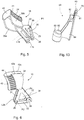
- An embodiment of an endotracheal device 1 is seen in perspective view in fig. 1 , and in a perspective exploded view in fig. 2 .
- the endotracheal device 1 comprises a handle part 2 and a stylet part 3.
- the stylet part 3 has an elongate hollow guide member 4 that extends into a bendable tip part 6 at a distal stylet end 7, and inside the handle part 2 at an opposite proximal stylet end 8.
- the handle part 2 defines a receptacle in form of a housing 9 that accommodates at least a part of a mechanism to bend the bendable tip part 6, and at least a part of a mechanism to eject from said stylet part 3 an endotracheal tube (not shown) sheathed on the stylet part 3.
- the elongate hollow guide member 4 is shown to be a smoothly curved pipe, and the bendable tip part 6 is not transparent.
- the shown curvature of the elongate hollow guide member 4 is an example and other curvatures, e.g. having larger or smaller radii, are foreseen within the scope of the present invention.
- the mechanism to bend the bendable tip part 6 includes a first string member 10 and a second string member 11 extending inside the elongate hollow guide member 4.
- the first string member 10 and the second string member 11 are both connected to a tip-shaping member 5 located at least partly inside a tubular cover 12 and having a first end 95 secured to the free distal tip 97 of the distal tip part 6 and an opposite second end 96 secured to the elongate hollow guide member 4 or the stylet part 3.
- the tubular cover 12 and the tip-shaping member 5 are comprised of the bendable tip part 6.
- the housing 9 is comprised of a first shell part 13 and an opposite second shell part 14 that, when assembled, provide a space for at least a part of an actuator means 15 for pulling and relaxing tensioning of the tip-shaping member 5 inside the tubular cover 12 by pulling and relating tensioning of the first string member 10 and the second string member 11, both of which are secured to said tip-shaping member 5 at different securing locations (not seen in fig. 1 and fig. 2 ) inside the tubular cover 12 of the bendable tip part 6.
- a tip part operating member 16 thus includes at least the tip-shaping member 5, the first string member 10 and the second string member 11.
- the actuator means 15 includes a suspension body 17, a first string operating member 18, and a second string operating member 19 pivotable suspended on the suspension body 17, as seen in more detail in the enlarged views of fig. 3 and fig. 4 , in which figs. 3 and 4 other structural components of the endotracheal device 1 have been left out to better visualize the pivoting "saddle"-arrangement of the string operating members 18,19 on the suspension body 17.
- a first string operating member 18 of the actuator means 15 includes a first bifurcated lever body 20 having opposite first legs L1a, L1b arranged on opposite sides of the suspension body 17 about a first pivot axis P1 to allow the first lever body 20 to move up and down in relation to the suspension body 17, as indicated by double-pointed arrow A1.
- a second string operating member 19 of the actuator means 15 includes a second bifurcated lever body 22 having opposite second legs L2a,L2b pivotably arranged about a second pivot axis P2 to allow the second lever body 22 to move up and down in relation to the suspension body 17, as indicated by double-pointed arrow A2.
- first legs L1a, L1b have similar structure, which structures therefore are described in common with reference to a first leg L1b, as seen best in fig. 4 .
- the first leg L1b of first lever body 20 has a first actuator lever arm 23 extending from the first pivot axis P1 to a first actuator 24.
- a first string operating lever arm 25 extends opposite the first actuator lever arm 23 so that a first fulcrum 26 is established at the first pivot axis P1.
- a first angle ⁇ 1 between the first actuator lever arm 23 and the first string operating lever arm 25 are typically equal to or less than 90°, but a first angle ⁇ 1 larger than 90° is not excluded.
- the first actuator lever arm 23 and the first string operating lever arm 25 are connected to each other via a first intermediate arm 27 extending between the end 23a of the first actuator lever arm 23, at the transition of the first actuator lever arm 23 into the first actuator 18, and the end 25a of the first string operating lever arm 25 opposite the first pivot axis P1 to confer structural strength to the first lever body 20.
- These three first arms, thus the first actuator lever arm 23, the first string operating lever arm 25, and the first intermediate arm 27 together forms an open triangular shape that makes the first lever body 20 lightweight and simple to mold, e.g. of a polymeric plastic material, such as a thermosetting material, without loosing the structural and dimensional strength needed for reliable and safe operation of the actuator means 15.
- the end 25a of the first string operating lever arm 25 opposite the first pivot axis P1 has a first cavity or a first hook 28 for engaging a first string-securing member 29, to which a first proximal string end 30a of the first string member 10 is connected, so that actuating the first string operating member 18 by applying a force to the first actuator 24 makes the first lever body 20 pivot about the first pivot axis P1 thereby moving the engaging first string-securing member 29 and first hook 28, or similar mating grasping means, lengthwise backwards inside the housing 9 to tension the first string member 10, which has a first distal string end 30b secured to the tip-shaping member 5, and pull the first string-securing location (not shown) at the tip-shaping member 5 away from the distal stylet end 7, thereby bending the tip-shaping member 5, and thus the tubular cover 12, that keeps movement of the first string member 10 and the tip-shaping member 5 under control, and prevents unintended lateral movement of any of the tip-shaping member 5
- the opposite second legs L2a,L2b of the second lever body 22 have similar structure, which structure therefore is described in common with reference to a second leg L2a.
- the second lever body 22 has a structure similar to the structure of the first lever body 20 and works in a similar manner. Accordingly, a second leg L2a of the second lever body 22 has a second actuator lever arm 31 extending from the second pivot axis P2 to a second actuator 32. A second string operating lever arm 33 extends opposite the second actuator lever arm 31 so that a second fulcrum 34 is established at the second pivot axis P2. A second angle ⁇ 2 between the second actuator lever arm 31 and the second string operating lever arm 33 is outlined similarly to the first angle ⁇ 1.
- the second actuator lever arm 31 and the second string operating lever arm 33 are connected to each other via a second intermediate arm 35 extending between the end 31a of the second actuator lever arm 31, at the transition of the second actuator lever arm 31 into the second actuator 32, and the free end 33a of the second string operating lever arm 33 opposite the second pivot axis P2, to confer structural strength to the second lever body 22.
- a second intermediate arm 35 extending between the end 31a of the second actuator lever arm 31, at the transition of the second actuator lever arm 31 into the second actuator 32, and the free end 33a of the second string operating lever arm 33 opposite the second pivot axis P2, to confer structural strength to the second lever body 22.
- the first lever body 20 these three second arms, thus the second actuator lever arm 31, the second string operating lever arm 33, and the second intermediate arm 34 together forms an open triangular shape.
- the end 33a of the second string operating lever arm 33 opposite the second pivot axis P2 has a second cavity or a second hook 36 for engaging a second string-securing member 37, to which a second proximal string end 38a of the second string member 11 is connected.
- Actuating the second string operating member 22 by applying a force to the second actuator 32 makes the second lever body 22 pivot about the second pivot axis P2 thereby moving the engaging second string-securing member 37 and second hook 36, or similar mating grasping means, simultaneously, lengthwise backwards inside the housing 9 to tension the second string member 11, which has a second distal string end 38b secured to the tip-shaping member 5, and pull the second string-securing location (not shown) at the tip-shaping member 5 away from the distal stylet end 7, thereby bending the tip-shaping member 5 by tensioning the second string-securing location.
- the second string operating member 19 pull at another string-securing location than the first string-securing location. In this manner it becomes possible to bend the bendable tip part 5 almost arbitrary and smoothly into any level of S-shape, C-shape or J-shape depending on the level of force applied to the respective actuators 24;32.
- the bendable tip part 5 can thus be given a variety of bended shapes and bending be customized for a certain airway anatomy by tensioning and relaxing tensioning of the respective string members 10,11 by operating the associated actuators, which considerably improves the ability of unobstructed passing of the stylet part 3 in between the vocal cords, even for difficult airways.
- the first string operating member 18 and the second string operating member 19 have similar design and are disposed in spaced relationship along the length of the suspension body 17 to pivot individually at the same time or at different times without jamming.
- first legs L1a, L1b of the first bifurcated lever body 20 extends into an U-shaped first actuator 24.
- the opposite first leg L1a, L1b extends into the first actuator legs 39a,39b of the U-shaped first actuator 24, which first actuator legs 39a,39b are connected by first bridging member 40 that has exterior ridges 41 for improved tactileness and increased friction when grasping the handle part 2 for operating and maneuvering the endotracheal device 1.
- the side view of fig. 6 shows the second string-operating member 19 but since the first string operating member 18 and the second string-operating member 19 in the present embodiment are identical, fig. 6 could quite as well show the first string-operating member 18.
- the opposite second legs L2a,L2b of the second bifurcated lever body 22 extends into an U-shaped second actuator 32.
- the opposite second leg L2a,L2b extends into the second actuator legs 42a,42b of the U-shaped second actuator 32, which second actuator legs 42a,42b are connected by second bridging member 43 that has exterior ridges 44 for improved tactileness and increased friction when grasping the handle part 2 for operating and maneuvering the endotracheal device 1.
- An exemplary string-securing member 29;37 can e.g. be a freely suspended pin extending crosswise between the first shell part 13 and the second shell part 14 inside the housing 9.
- the pin is not connected to any of the shell parts 13,14 because it shall be able to move in response to pivoting the lever bodies 20,22.
- the engagement between the hook 28;36 and the string-securing member 29;37 however keeps the string member 10; 11 under tension so that the string-securing member 29;37 not accidentally can disengage the hook 28:36 or cavity.
- Alternative ways of securing a string member to a lever body in a manner that allows the lever body to pull the string member backward when tensioned and move forward when tension is relieved is within the scope of the present invention.
- a string member can in the alternative simply be secured by a knot in an eye of the lever body.
- Figs. 7 and 8 are perspective views of the suspension body 17 that has a distal suspension body end 45 and an opposite proximal suspension body end 46, respectively.
- the suspension body 17 has opposite lengthwise extending first 47 and second side faces 48, an upper ridge 49 and a lower edge 50 extending lengthwise between said side faces 47,48.
- the upper ridge 49 is configured with alternating first crest 51 and first sag 52 at the distal suspension body end 45, and second crest 53 and second sag 54 at the proximal suspension body end 46.
- the alternating arrangement of crests 51,53 and sags 52,54 provides points of discontinuity along the curvature of the upper ridge 49 to define a first seat 55 for the first actuator 24 and a second seat 56 for the second actuator 32 when pivoted about respective pivot axis P1, P2.
- Both the opposite first side face 47 and second side face 48 has a plurality of protruding securing pins 57 arranged to mate into corresponding female securing means 58 of the shell parts 13,14 of the housing 9 to secure the suspension body 17 in a manner inside the housing 9 wherein none of the suspension body 17, the securing pins 57 or the female securing means 58, e.g. bush mountings, can obstruct the operation of the actuator means 15 and the tube ejecting mechanism.
- the securing pins 57 are arranged along or in the vicinity of the annular outer edge of the suspension body 17.
- a groove 59 or recess in the first face 48 serve to receive, mount and align the proximal stylet end 8 of the elongate hollow guide member 4 for securing the elongate hollow guide member 4 firmly to the suspension body 17.
- Securing can e.g. be achieved by gluing or by traverse pins.
- the protruding securing pins 57 can be provided at the shell parts 13,24 and the female securing means 58 be provided at the suspension body 17.
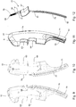
- Figs. 9, 10 and 11 show the shell parts 12,13 apart from each other and in assembled state to obtain the housing 9.
- the proximal housing end 60 is closed, whereas the distal housing end 61 is open for passage of the stylet part 3.
- the upper lengthwise housing edge 62 has a proximal opening 63 for the pivotable passage of the first actuator 24 of the first string operating member 18 and a distal opening 64 for the pivotable passage of the second actuator 32 of the second string-operating member 19.
- the first actuator 24 and the second actuator 32 constitute the buttons, which the operator uses to confer a desired curvature and shape to the distal tip part 6.
- a tube ejecting mechanism 65 to get the endotracheal tube (not shown) off the stylet part 3 includes a ratchet mechanism 66 with a third actuator 67 that protrudes from the housing 9 opposite the proximal opening 63 and the distal opening 64.
- the ratchet mechanism 66 has a rack part 68 and a wedge part 69, which wedge part 69 is seen in fig. 13 .
- the rack part 69 is comprised of a first elongate stationary rack part 70, a second elongate stationary rack part 71 and a moveable third elongate rack part 72, which moveable third elongate rack part 72 is shown in fig. 12 .
- the moveable third elongate rack part 72 is, as shown in fig. 2 disposed between the first elongate stationary rack part 70 and the second stationary elongate rack part 71.
- the three rack parts 70,71,72 extend lengthwise from the proximal housing end 61 towards the distal housing end 60 inside the housing 9 opposite the proximal opening 63 and the distal opening 64.
- the third actuator 67 of the moveable third elongate rack part 72 protrudes through an ejector slot 74 in the housing 9 towards the proximal housing end 61 opposite the proximal opening 63 and the distal opening 6 for pivotable passage of the actuators 24,32.
- the third actuator 67 is provided at a proximal end 73 of the moveable third elongate rack part 72 to be accessible to move said moveable third elongate rack part 72 in a translatory movement that is restricted by the ejector slot 74 towards the bendable tip part 6.
- the moveable third elongate rack part 72 which is shown in the separate view of fig. 12 , is suspended inside the housing 9 by means of a spring 75 or similar resilient means, such as an elastic strap.
- the spring 75 is stretched and tensioned when the moveable third elongate rack part 72 is moved lengthwise along the housing 9 upon a stroke of the third actuator 67 in order to displace the moveable third elongate rack part 72 forward between the first stationary elongate rack part 70 and second stationary elongate rack part 71.
- the first elongate stationary rack part 70 has first teeth 76
- the second elongate stationary rack part 71 has second teeth 77
- the moveable third elongate rack part 72 has third teeth 78.
- the wedge part 69 has a center wedge part 79 that engages between the third teeth 78 of the moveable third rack part 72.
- the center wedge part 79 is located between a first lateral wedge part 80 to engage the first teeth 76 of the first elongate stationary rack part 7 and a second lateral wedge part 81 to engage the second teeth 77 of the second elongate stationary rack part 71.
- the center wedge part 79, the first lateral wedge part 80, and the second lateral wedge part 81 are provided at a proximal end 82 of the wedge part 69 and a tube connector 83 is provided at the distal wedge part 84.
- the tube connector 83 is a cylindrical tapering plug with a bore 85 for receiving the elongate hollow guide member 4 to allow the wedge part 69 to be fitted in fixed position on said elongate hollow guide member 4, or preferably to slide along said elongate hollow guide member 4 in response to operating the third actuator 67 and thus the movable third elongate rack 72 to eject an endotracheal tube 86, as shown in general in figs. 14 and 15 .
- the endotracheal tube 86 has a tube part 87a and an airway connector 87b that mates around the tube connector 83 of the wedge part 69, to push the endotracheal tube 86 off the elongate hollow guide member 4 when the third actuator 67 of the moveable third rack part 72 displaces the wedge part 69 and thus the endotracheal tube 86 forward towards the distal stylet end 7.
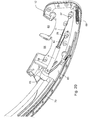
- the ejecting steps are seen more clearly in figs. 16 - 19 .
- the state shown in figs. 16 and 17 corresponds to the state shown in fig. 14
- the state shown in figs. 18 and 19 corresponds to the state shown in fig. 15 where the endotracheal tube 86 has been moved closer to the distal tip part 6 by means of the tube ejecting mechanism 65.
- the second shell part 13 has been removed to illustrate the interior components and structures accommodated by the handle part 2.
- the positions of the wedge part 69 in relation to the stationary rack parts 70,71, the third actuator 67, and the moveable third rack part 72 of the ratchet mechanism 66 inside the housing 9 is shown in the starting position ready for the endotracheal procedure.
- the moveable third rack part 72 is in retracted position in the housing 9, and the spring 75, that has one spring end 88 secured at a spring securing location 89 inside the proximal housing end 61 of the housing 9, and an opposite end 90 secured to the proximal end 91 of the moveable third elongate rack part 72, is in relaxed state.
- An endotracheal tube 86 is sheathed on the elongate hollow guide member 4, and the airway connector 87 of the endotracheal tube 86 mates around the tube connector 83 of the wedge part 69.
- the first 80 and second lateral wedge parts 81 engage the adjacent first teeth 76 and the second teeth 77 so that the wedge part 69 cannot return towards the proximal housing end 61 when the moveable third elongate rack part 72 returns to the proximal housing end 61 to repeat the stroke.
- another third tooth or section of third teeth 78 closer to the distal end 92 of the moveable third elongate rack part 72 is made available and exposed for further displacing the wedge part 69 yet a stroke forward by its engagement with the center wedge part 79.
- Strokes can be repeated as long as the length of the moveable third elongate rack part 72 is available for engagement with the center wedge part 79.
- the tube connector 83 may not automatically be released from the airway connector 87 to leave the endotracheal tube 86 in trachea for subsequent connection to an appropriate ventilation equipment upon retraction of the stylet part 3.
- the operator may chose to set the endotracheal tube 86 free before the wedge part 69 reaches the distal end 92 of the moveable third elongate rack part 72. Accordingly, the operator may choose to separate the endotracheal tube 86 and the endotracheal device 1 at any convenient stage during the endotracheal procedure.
- the first string member 10 e.g. a metal wire
- the first string-securing member 29 e.g. a cross pin
- the second string member 10 is secured to the second string-securing member 37, e.g. a cross pin, lengthwise offset the first string member 10.
- the string-securing members 29;37 are grasped by the first string operating member 18, and the second string operating member 19, respectively, as described above, to pull the string members 10,11, simultaneously or independently, to same or different extent, in and out of the elongate hollow member 4 a distance corresponding to up to the maximum length achievable by a full depression and pivoting of a string operating member.
- This novel and inventive configuration and design of an endotracheal device 1 provides a multitude of options and a huge degree of freedom for configuring the shape of the bendable tip part 6 to adopt a shape suited for maneuvering in almost any imaginable airway anatomy.
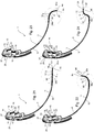
- FIG. 21 - 24 Various examples of curvatures and shapes that can be given to the bendable tip part 6 by operating the tip part operating member 16 using the actuator means 15 is shown in the subsequent figs. 21 - 24 .
- the endotracheal device 1 shown in figs. 21 - 24 is shown with transparent elongate hollow guide member 4 and transparent tubular cover 12 to illustrate that the first string member 10 and the second string member 11 extend along the length of said elongate hollow guide member 4 and further inside the tubular cover 12, inside which the tip-shaping member 5 is located.
- the first string member 10 is secured at a first string-securing location 93 retracted from the first end 95 of the tip-shaping member 5, in the present case on top of a tip-shaping member 5 in form of a plate spring, to be operated by means of the first actuator 24, as indicated by curved arrow A1.
- the second string member 11 is secured to the tip-shaping member 5 at the bottom of the tip-shaping member 5 at a second string-securing location 94 downstream the first string-securing location 93 to be operated by means of the second actuator 32, as indicated by curved arrow A2.
- the first string-securing location 93 is both lateral and lengthwise offset the second string-securing location 94 and closer to the handle part 2, as seen more clearly in the associated fig. 24 , which is an enlarged scale view of the bendable tip part 6 seen in fig. 23 .
- both the first string operating member 18 and the second string operating member 19 have been actuated by depressing the first actuator 24, as indicated by arrow A1, and the second actuator 32, as indicated by arrow A2. Pressing on both the actuators 24,32 move both string-securing members 29,37 back inside the housing 9 whereby both string-securing locations 93,94 are pulled closer to the handle part 2, to provide the bendable tip part 6 with an S-shape.
- any possible movement by the tip-shaping member 5 in response to operation of the actuators 24,32 are also controlled and confined by the presence of said tubular cover 12 that restricts lateral movement of the plate spring 5 beyond the border of the tubular cover 12, but permits at least lengthwise bending because of flexibility of the tubular cover 12 of the bendable tip part 6.
- Fig. 25 is an enlarged scale view of the first embodiment of a tip-shaping member 5 in the S-configuration seen in fig. 24 .
- a second embodiment of a tip-shaping member 5' is seen in fig. 26, 27 and 278.
- the shapes and configuration of the bendable tip part 6 shown in figs. 21, 22 and 23 can also be obtained by implementation of the second embodiment of a tip-shaping member 5', which second embodiment of a tip-shaping member 5' has laterally offset first string-securing location 93' and second string-securing location 94'.
- first string-securing location 93', 94' are not lengthwise offset.
- the second embodiment of a tip-shaping member 5' is in a relaxed condition corresponding to the condition shown in fig. 21 for the first embodiment of a tip-shaping member 5.
- the second embodiment of a tip-shaping member 5' is in same C-shaped configuration as in fig. 22
- the second embodiment of a tip-shaping member 5' is in a J-shaped configuration similar to the configuration shown in fig. 23 .
- first lever body and the second lever body are described as a triangle with a center hole, other lever body designs are within the scope of the present invention.
- the triangular structure can e.g. be replaced by a solid triangular plate, in which case the edge areas of the triangle are equivalent to the arms of the triangular structure and is utilized and functions in a similar manner.
- Other shapes than triangular, such as oval, polygonal and circular are also possible within the scope of the present invention.
- the outline of the first actuator and of the second actuator is curved, preferably having similar curvature as defined by the pivot radius.
- first lever body and the second lever body where both designed with pivotable lever arms.
- actuators may include alternatives to such lever bodies.
- axial displacing the first distal securing location and the second distal securing location may in the alternative be provided by connecting the first proximal string end of the corresponding first string member and the second proximal string end of the corresponding second proximal string member, respectively, to e.g. a toggle mechanism, an articulated mechanism, a rotating mechanism, or even a gear transmission.
- a string member can e.g. be any kind of elongate thin pulling means that can fit inside the elongate hollow guide member and having a sufficient strength to pull the tip-shaping member without accidentally rupturing when tensioned.
- Suitable string members include but are not limited to a metal wire, a nylon wire, e.g. a fish line, or similar means that can tension the tip-shaping member in response to application of a force onto a string operating member.
- tip-shaping members adapted to be operatively accommodated inside the tubular cover include but are not limited to a flat spring, e.g. a thin strip of spring steel, or a tension spring, e.g. a coiled spring.
- the embodiment of the endotracheal device of the present invention includes a suspension body to amongst other suspend the string operating members, and control the orientation and pivoting of said string operating members.
- the suspension body is designed and arranged to restrict and stop downwards movement of an actuator.
- the suspension body further facilitates the correct functional and mechanical assembling of the relevant components of the mechanism to bend the bendable tip part, and the relevant components of the mechanism to eject the endotracheal tube off the stylet part.
- the endotracheal device may however be designed without suspension body and the string operating members be pivotable suspended directly to e.g. a pin crosswise the shell part of the housing. Stops for preventing the actuators from been depressed too far into the housing can simply protrude from a shell part inside the space delimited by said shell parts.
- the present invention has a minimum of structural components, which makes productions costs low and the risk that a structural components fails is at an absolute minimum.
- the handle part of the endotracheal device of the present invention has a very ergonomic design.
- the elongate hollow guide member can advantageously be made of metal, such as malleable aluminium, which allows the stylet part to be easily adapted to any desired anatomy and use.
- the advantages of the endotracheal device and endotracheal procedure and methods described herein further include, without limitation, the ability to control the shape of the distal tip part of an endotracheal tube, the ability to respond to unique anatomical differences in tracheal location and shape.
- the entire endotracheal device may be disposable in its entirety, or the stylet part may be a separate disposable unit for one time use and the handle part be for reuse. So the stylet part can be a disposable stylet part while continuing use of the handle part is within the scope of the present invention.
- the endotracheal device can be a kit of parts, which parts e.g. may include a reusable handle part and a selection of stylet parts and endotracheal tubes to go with the stylet part.
- kits of parts are within the scope of the present invention.
Priority Applications (4)
| Application Number | Priority Date | Filing Date | Title |
|---|---|---|---|
| EP16204087.7A EP3335754A1 (de) | 2016-12-14 | 2016-12-14 | Endotracheale intubationsvorrichtung |
| US16/469,122 US10953177B2 (en) | 2016-12-14 | 2017-12-13 | Endotracheal tube-inserting device |
| EP17825170.8A EP3554604B1 (de) | 2016-12-14 | 2017-12-13 | Vorrichtung zum einführen eines endotrachealtubus |
| PCT/EP2017/082677 WO2018109033A1 (en) | 2016-12-14 | 2017-12-13 | An endotracheal tube-inserting device |
Applications Claiming Priority (1)
| Application Number | Priority Date | Filing Date | Title |
|---|---|---|---|
| EP16204087.7A EP3335754A1 (de) | 2016-12-14 | 2016-12-14 | Endotracheale intubationsvorrichtung |
Publications (1)
| Publication Number | Publication Date |
|---|---|
| EP3335754A1 true EP3335754A1 (de) | 2018-06-20 |
Family
ID=57570300
Family Applications (2)
| Application Number | Title | Priority Date | Filing Date |
|---|---|---|---|
| EP16204087.7A Withdrawn EP3335754A1 (de) | 2016-12-14 | 2016-12-14 | Endotracheale intubationsvorrichtung |
| EP17825170.8A Active EP3554604B1 (de) | 2016-12-14 | 2017-12-13 | Vorrichtung zum einführen eines endotrachealtubus |
Family Applications After (1)
| Application Number | Title | Priority Date | Filing Date |
|---|---|---|---|
| EP17825170.8A Active EP3554604B1 (de) | 2016-12-14 | 2017-12-13 | Vorrichtung zum einführen eines endotrachealtubus |
Country Status (3)
| Country | Link |
|---|---|
| US (1) | US10953177B2 (de) |
| EP (2) | EP3335754A1 (de) |
| WO (1) | WO2018109033A1 (de) |
Cited By (1)
| Publication number | Priority date | Publication date | Assignee | Title |
|---|---|---|---|---|
| WO2021224054A1 (de) * | 2020-05-06 | 2021-11-11 | Reiner Kunz | Intubationshilfe |
Families Citing this family (8)
| Publication number | Priority date | Publication date | Assignee | Title |
|---|---|---|---|---|
| GB2563567B (en) * | 2017-05-05 | 2022-01-05 | Flexicare Group Ltd | Intubation devices |
| AU2019295408A1 (en) * | 2018-06-25 | 2022-03-10 | Airway Medical Innovations Pty Ltd | Airway manipulator devices |
| CA3183162A1 (en) | 2020-06-19 | 2021-12-23 | Jake Anthony Sganga | Systems and methods for guidance of intraluminal devices within the vasculature |
| CN112617728B (zh) * | 2020-12-30 | 2024-01-23 | 上海市胸科医院 | 一种气管镜镜鞘及其操作装置 |
| AU2022305235A1 (en) | 2021-07-01 | 2024-01-18 | Remedy Robotics, Inc. | Vision-based position and orientation determination for endovascular tools |
| US11707332B2 (en) | 2021-07-01 | 2023-07-25 | Remedy Robotics, Inc. | Image space control for endovascular tools |
| CN114177459A (zh) * | 2021-11-29 | 2022-03-15 | 重庆安纳生生物工程有限公司 | 气管插管辅助结构 |
| EP4272792A1 (de) * | 2022-05-04 | 2023-11-08 | Albert-Ludwigs-Universität Freiburg | Medizinisches instrument für die intubation |
Citations (13)
| Publication number | Priority date | Publication date | Assignee | Title |
|---|---|---|---|---|
| US5016614A (en) * | 1985-11-07 | 1991-05-21 | Macallister Niall P | Endotracheal intubation apparatus |
| US5327881A (en) * | 1993-02-26 | 1994-07-12 | Beth Israel Hospital Association | Fiberoptic intubating stylet |
| EP1224904A2 (de) * | 2001-01-09 | 2002-07-24 | XION GmbH | Endoskopartige Vorrichtung, insbesondere für die Notfallintubation |
| US20030024532A1 (en) * | 2001-08-02 | 2003-02-06 | Sniadach Joseph A. | Adjustable ventilation mask for a patient |
| US6539942B2 (en) | 2001-04-19 | 2003-04-01 | Richard Schwartz | Endotracheal intubation device |
| EP1803481A2 (de) * | 2005-12-30 | 2007-07-04 | Biosense Webster, Inc. | Bidirektionales Griffteil mit einem Doppelhebelmechanismus |
| WO2009026095A1 (en) * | 2007-08-23 | 2009-02-26 | The Cleveland Clinic Foundation | Apparatus and method for intubating an airway of a patient |
| WO2011025297A2 (ko) * | 2009-08-27 | 2011-03-03 | 고려대학교 산학협력단 | 삽관 튜브 가이드 장치 |
| WO2011119521A1 (en) * | 2010-03-22 | 2011-09-29 | Tufts Medical Center, Inc. | Fiber optic intubating device |
| US8382665B1 (en) * | 2009-02-12 | 2013-02-26 | Alfred Fam | Endotracheal tube placement system and method |
| US20130245372A1 (en) * | 2012-03-13 | 2013-09-19 | Gentle And Tender Co., Ltd. | Endotracheal intubation assistance apparatus |
| US20130255671A1 (en) | 2012-03-12 | 2013-10-03 | Furman Medical Llc | Manually articulated intubation stylet, intubation device and intubation method |
| US20150096556A1 (en) * | 2013-10-06 | 2015-04-09 | Robert S. Marks | Steerable endotracheal intubation apparatus, endotracheal intubation component system and endotracheal tube of same |
Family Cites Families (3)
| Publication number | Priority date | Publication date | Assignee | Title |
|---|---|---|---|---|
| US20090064999A1 (en) * | 2007-09-12 | 2009-03-12 | E. Benson Hood Laboratories | Tracheostomy tube with inner cannula and obturator for regular and extra-long stomas |
| US10413708B2 (en) * | 2014-08-05 | 2019-09-17 | Jeffrey Thomas Loh | Swivel enhanced guidewire and related methods |
| US10682503B2 (en) * | 2015-06-30 | 2020-06-16 | Sanovas Intellectual Property, Llc | Sinus ostia dilation system |
-
2016
- 2016-12-14 EP EP16204087.7A patent/EP3335754A1/de not_active Withdrawn
-
2017
- 2017-12-13 US US16/469,122 patent/US10953177B2/en active Active
- 2017-12-13 WO PCT/EP2017/082677 patent/WO2018109033A1/en unknown
- 2017-12-13 EP EP17825170.8A patent/EP3554604B1/de active Active
Patent Citations (13)
| Publication number | Priority date | Publication date | Assignee | Title |
|---|---|---|---|---|
| US5016614A (en) * | 1985-11-07 | 1991-05-21 | Macallister Niall P | Endotracheal intubation apparatus |
| US5327881A (en) * | 1993-02-26 | 1994-07-12 | Beth Israel Hospital Association | Fiberoptic intubating stylet |
| EP1224904A2 (de) * | 2001-01-09 | 2002-07-24 | XION GmbH | Endoskopartige Vorrichtung, insbesondere für die Notfallintubation |
| US6539942B2 (en) | 2001-04-19 | 2003-04-01 | Richard Schwartz | Endotracheal intubation device |
| US20030024532A1 (en) * | 2001-08-02 | 2003-02-06 | Sniadach Joseph A. | Adjustable ventilation mask for a patient |
| EP1803481A2 (de) * | 2005-12-30 | 2007-07-04 | Biosense Webster, Inc. | Bidirektionales Griffteil mit einem Doppelhebelmechanismus |
| WO2009026095A1 (en) * | 2007-08-23 | 2009-02-26 | The Cleveland Clinic Foundation | Apparatus and method for intubating an airway of a patient |
| US8382665B1 (en) * | 2009-02-12 | 2013-02-26 | Alfred Fam | Endotracheal tube placement system and method |
| WO2011025297A2 (ko) * | 2009-08-27 | 2011-03-03 | 고려대학교 산학협력단 | 삽관 튜브 가이드 장치 |
| WO2011119521A1 (en) * | 2010-03-22 | 2011-09-29 | Tufts Medical Center, Inc. | Fiber optic intubating device |
| US20130255671A1 (en) | 2012-03-12 | 2013-10-03 | Furman Medical Llc | Manually articulated intubation stylet, intubation device and intubation method |
| US20130245372A1 (en) * | 2012-03-13 | 2013-09-19 | Gentle And Tender Co., Ltd. | Endotracheal intubation assistance apparatus |
| US20150096556A1 (en) * | 2013-10-06 | 2015-04-09 | Robert S. Marks | Steerable endotracheal intubation apparatus, endotracheal intubation component system and endotracheal tube of same |
Non-Patent Citations (3)
| Title |
|---|
| BURKLE CM; WALSH MT; HARRISON BA; CURRY TB; ROSE SH: "Airway management after failure to intubate by direct laryngoscopy: outcomes in a large teaching hospital", CAN J ANAESTH., vol. 52, no. 6, 2005, pages 634 - 640 |
| M. CHANDLER: "Tracheal intubation and sore throat: A mechanical explanation", ANAESTHESIA, vol. 57, 2002, pages 155 - 161 |
| ROSE DK; COHEN MM: "The airway: problems and predictions in 18,500 patients", CAN J ANAESTH., vol. 41, no. 5, 1994, pages 372 - 383 |
Cited By (1)
| Publication number | Priority date | Publication date | Assignee | Title |
|---|---|---|---|---|
| WO2021224054A1 (de) * | 2020-05-06 | 2021-11-11 | Reiner Kunz | Intubationshilfe |
Also Published As
| Publication number | Publication date |
|---|---|
| WO2018109033A1 (en) | 2018-06-21 |
| US10953177B2 (en) | 2021-03-23 |
| EP3554604A1 (de) | 2019-10-23 |
| EP3554604B1 (de) | 2021-02-24 |
| US20200023151A1 (en) | 2020-01-23 |
Similar Documents
| Publication | Publication Date | Title |
|---|---|---|
| EP3335754A1 (de) | Endotracheale intubationsvorrichtung | |
| US6539942B2 (en) | Endotracheal intubation device | |
| US20200338290A1 (en) | Tracheal intubation system including a laryngoscope | |
| US20230173209A1 (en) | Articulating stylet | |
| US6174281B1 (en) | Laryngoscope | |
| US5163941A (en) | Intubation device | |
| CN108882829B (zh) | 能够成像的双向可调气管插管 | |
| US10478578B2 (en) | Bougie with a controllable tip | |
| JPH0622909A (ja) | 挿入スチレットを有する喉頭鏡 | |
| US20130245372A1 (en) | Endotracheal intubation assistance apparatus | |
| KR20170130353A (ko) | 삽관 장치 | |
| JP2017508519A (ja) | 挿管を容易にするためのシステムおよび方法 | |
| US20140128681A1 (en) | Intubation guide assembly | |
| WO2019240655A1 (en) | An endotracheal tube-inserting device | |
| US20180085031A1 (en) | Devices and methods for airway measurement | |
| EP3335755A1 (de) | Endotracheale intubationsvorrichtung | |
| US8425409B2 (en) | Laryngoscope | |
| TW201509450A (zh) | 插管輔助裝置 | |
| MXPA98006512A (en) | Laringosco |
Legal Events
| Date | Code | Title | Description |
|---|---|---|---|
| PUAI | Public reference made under article 153(3) epc to a published international application that has entered the european phase |
Free format text: ORIGINAL CODE: 0009012 |
|
| AK | Designated contracting states |
Kind code of ref document: A1 Designated state(s): AL AT BE BG CH CY CZ DE DK EE ES FI FR GB GR HR HU IE IS IT LI LT LU LV MC MK MT NL NO PL PT RO RS SE SI SK SM TR |
|
| AX | Request for extension of the european patent |
Extension state: BA ME |
|
| STAA | Information on the status of an ep patent application or granted ep patent |
Free format text: STATUS: THE APPLICATION IS DEEMED TO BE WITHDRAWN |
|
| 18D | Application deemed to be withdrawn |
Effective date: 20181221 |