EP3333953A1 - Elektrochemische wasserstoffpumpe - Google Patents
Elektrochemische wasserstoffpumpe Download PDFInfo
- Publication number
- EP3333953A1 EP3333953A1 EP17204251.7A EP17204251A EP3333953A1 EP 3333953 A1 EP3333953 A1 EP 3333953A1 EP 17204251 A EP17204251 A EP 17204251A EP 3333953 A1 EP3333953 A1 EP 3333953A1
- Authority
- EP
- European Patent Office
- Prior art keywords
- gas diffusion
- cathode
- diffusion layer
- cathode gas
- anode
- Prior art date
- Legal status (The legal status is an assumption and is not a legal conclusion. Google has not performed a legal analysis and makes no representation as to the accuracy of the status listed.)
- Granted
Links
Images


Classifications
-
- C—CHEMISTRY; METALLURGY
- C01—INORGANIC CHEMISTRY
- C01B—NON-METALLIC ELEMENTS; COMPOUNDS THEREOF; METALLOIDS OR COMPOUNDS THEREOF NOT COVERED BY SUBCLASS C01C
- C01B3/00—Hydrogen; Gaseous mixtures containing hydrogen; Separation of hydrogen from mixtures containing it; Purification of hydrogen
- C01B3/50—Separation of hydrogen or hydrogen containing gases from gaseous mixtures, e.g. purification
- C01B3/56—Separation of hydrogen or hydrogen containing gases from gaseous mixtures, e.g. purification by contacting with solids; Regeneration of used solids
- C01B3/58—Separation of hydrogen or hydrogen containing gases from gaseous mixtures, e.g. purification by contacting with solids; Regeneration of used solids including a catalytic reaction
-
- B—PERFORMING OPERATIONS; TRANSPORTING
- B01—PHYSICAL OR CHEMICAL PROCESSES OR APPARATUS IN GENERAL
- B01D—SEPARATION
- B01D53/00—Separation of gases or vapours; Recovering vapours of volatile solvents from gases; Chemical or biological purification of waste gases, e.g. engine exhaust gases, smoke, fumes, flue gases, aerosols
- B01D53/32—Separation of gases or vapours; Recovering vapours of volatile solvents from gases; Chemical or biological purification of waste gases, e.g. engine exhaust gases, smoke, fumes, flue gases, aerosols by electrical effects other than those provided for in group B01D61/00
- B01D53/326—Separation of gases or vapours; Recovering vapours of volatile solvents from gases; Chemical or biological purification of waste gases, e.g. engine exhaust gases, smoke, fumes, flue gases, aerosols by electrical effects other than those provided for in group B01D61/00 in electrochemical cells
-
- C—CHEMISTRY; METALLURGY
- C01—INORGANIC CHEMISTRY
- C01B—NON-METALLIC ELEMENTS; COMPOUNDS THEREOF; METALLOIDS OR COMPOUNDS THEREOF NOT COVERED BY SUBCLASS C01C
- C01B3/00—Hydrogen; Gaseous mixtures containing hydrogen; Separation of hydrogen from mixtures containing it; Purification of hydrogen
- C01B3/50—Separation of hydrogen or hydrogen containing gases from gaseous mixtures, e.g. purification
- C01B3/501—Separation of hydrogen or hydrogen containing gases from gaseous mixtures, e.g. purification by diffusion
- C01B3/503—Separation of hydrogen or hydrogen containing gases from gaseous mixtures, e.g. purification by diffusion characterised by the membrane
-
- C—CHEMISTRY; METALLURGY
- C25—ELECTROLYTIC OR ELECTROPHORETIC PROCESSES; APPARATUS THEREFOR
- C25B—ELECTROLYTIC OR ELECTROPHORETIC PROCESSES FOR THE PRODUCTION OF COMPOUNDS OR NON-METALS; APPARATUS THEREFOR
- C25B1/00—Electrolytic production of inorganic compounds or non-metals
- C25B1/01—Products
- C25B1/02—Hydrogen or oxygen
- C25B1/04—Hydrogen or oxygen by electrolysis of water
-
- C—CHEMISTRY; METALLURGY
- C25—ELECTROLYTIC OR ELECTROPHORETIC PROCESSES; APPARATUS THEREFOR
- C25B—ELECTROLYTIC OR ELECTROPHORETIC PROCESSES FOR THE PRODUCTION OF COMPOUNDS OR NON-METALS; APPARATUS THEREFOR
- C25B9/00—Cells or assemblies of cells; Constructional parts of cells; Assemblies of constructional parts, e.g. electrode-diaphragm assemblies; Process-related cell features
- C25B9/05—Pressure cells
-
- H—ELECTRICITY
- H01—ELECTRIC ELEMENTS
- H01M—PROCESSES OR MEANS, e.g. BATTERIES, FOR THE DIRECT CONVERSION OF CHEMICAL ENERGY INTO ELECTRICAL ENERGY
- H01M8/00—Fuel cells; Manufacture thereof
- H01M8/02—Details
- H01M8/0202—Collectors; Separators, e.g. bipolar separators; Interconnectors
- H01M8/023—Porous and characterised by the material
- H01M8/0232—Metals or alloys
-
- H—ELECTRICITY
- H01—ELECTRIC ELEMENTS
- H01M—PROCESSES OR MEANS, e.g. BATTERIES, FOR THE DIRECT CONVERSION OF CHEMICAL ENERGY INTO ELECTRICAL ENERGY
- H01M8/00—Fuel cells; Manufacture thereof
- H01M8/02—Details
- H01M8/0271—Sealing or supporting means around electrodes, matrices or membranes
-
- H—ELECTRICITY
- H01—ELECTRIC ELEMENTS
- H01M—PROCESSES OR MEANS, e.g. BATTERIES, FOR THE DIRECT CONVERSION OF CHEMICAL ENERGY INTO ELECTRICAL ENERGY
- H01M8/00—Fuel cells; Manufacture thereof
- H01M8/04—Auxiliary arrangements, e.g. for control of pressure or for circulation of fluids
- H01M8/04082—Arrangements for control of reactant parameters, e.g. pressure or concentration
- H01M8/04201—Reactant storage and supply, e.g. means for feeding, pipes
-
- H—ELECTRICITY
- H01—ELECTRIC ELEMENTS
- H01M—PROCESSES OR MEANS, e.g. BATTERIES, FOR THE DIRECT CONVERSION OF CHEMICAL ENERGY INTO ELECTRICAL ENERGY
- H01M8/00—Fuel cells; Manufacture thereof
- H01M8/06—Combination of fuel cells with means for production of reactants or for treatment of residues
- H01M8/0662—Treatment of gaseous reactants or gaseous residues, e.g. cleaning
- H01M8/0681—Reactant purification by the use of electrochemical cells
-
- H—ELECTRICITY
- H01—ELECTRIC ELEMENTS
- H01M—PROCESSES OR MEANS, e.g. BATTERIES, FOR THE DIRECT CONVERSION OF CHEMICAL ENERGY INTO ELECTRICAL ENERGY
- H01M8/00—Fuel cells; Manufacture thereof
- H01M8/14—Fuel cells with fused electrolytes
- H01M8/141—Fuel cells with fused electrolytes the anode and the cathode being gas-permeable electrodes or electrode layers
-
- H—ELECTRICITY
- H01—ELECTRIC ELEMENTS
- H01M—PROCESSES OR MEANS, e.g. BATTERIES, FOR THE DIRECT CONVERSION OF CHEMICAL ENERGY INTO ELECTRICAL ENERGY
- H01M8/00—Fuel cells; Manufacture thereof
- H01M8/24—Grouping of fuel cells, e.g. stacking of fuel cells
- H01M8/2465—Details of groupings of fuel cells
- H01M8/247—Arrangements for tightening a stack, for accommodation of a stack in a tank or for assembling different tanks
- H01M8/248—Means for compression of the fuel cell stacks
-
- B—PERFORMING OPERATIONS; TRANSPORTING
- B01—PHYSICAL OR CHEMICAL PROCESSES OR APPARATUS IN GENERAL
- B01D—SEPARATION
- B01D2256/00—Main component in the product gas stream after treatment
- B01D2256/16—Hydrogen
-
- H—ELECTRICITY
- H01—ELECTRIC ELEMENTS
- H01M—PROCESSES OR MEANS, e.g. BATTERIES, FOR THE DIRECT CONVERSION OF CHEMICAL ENERGY INTO ELECTRICAL ENERGY
- H01M8/00—Fuel cells; Manufacture thereof
- H01M8/10—Fuel cells with solid electrolytes
- H01M2008/1095—Fuel cells with polymeric electrolytes
-
- Y—GENERAL TAGGING OF NEW TECHNOLOGICAL DEVELOPMENTS; GENERAL TAGGING OF CROSS-SECTIONAL TECHNOLOGIES SPANNING OVER SEVERAL SECTIONS OF THE IPC; TECHNICAL SUBJECTS COVERED BY FORMER USPC CROSS-REFERENCE ART COLLECTIONS [XRACs] AND DIGESTS
- Y02—TECHNOLOGIES OR APPLICATIONS FOR MITIGATION OR ADAPTATION AGAINST CLIMATE CHANGE
- Y02E—REDUCTION OF GREENHOUSE GAS [GHG] EMISSIONS, RELATED TO ENERGY GENERATION, TRANSMISSION OR DISTRIBUTION
- Y02E60/00—Enabling technologies; Technologies with a potential or indirect contribution to GHG emissions mitigation
- Y02E60/30—Hydrogen technology
- Y02E60/36—Hydrogen production from non-carbon containing sources, e.g. by water electrolysis
-
- Y—GENERAL TAGGING OF NEW TECHNOLOGICAL DEVELOPMENTS; GENERAL TAGGING OF CROSS-SECTIONAL TECHNOLOGIES SPANNING OVER SEVERAL SECTIONS OF THE IPC; TECHNICAL SUBJECTS COVERED BY FORMER USPC CROSS-REFERENCE ART COLLECTIONS [XRACs] AND DIGESTS
- Y02—TECHNOLOGIES OR APPLICATIONS FOR MITIGATION OR ADAPTATION AGAINST CLIMATE CHANGE
- Y02E—REDUCTION OF GREENHOUSE GAS [GHG] EMISSIONS, RELATED TO ENERGY GENERATION, TRANSMISSION OR DISTRIBUTION
- Y02E60/00—Enabling technologies; Technologies with a potential or indirect contribution to GHG emissions mitigation
- Y02E60/30—Hydrogen technology
- Y02E60/50—Fuel cells
Definitions
- the present disclosure relates to an electrochemical hydrogen pump.
- a method has been known in which a MEA configured with an electrolyte membrane, feeders (gas diffusion layers), catalyst layers, and so forth is used, a voltage is applied between an anode and a cathode of the MEA, and high-pressure hydrogen gas (cathode gas) is thereby generated on a cathode side of the MEA (for example, see Japanese Unexamined Patent Application Publication No. 2001-342587 ).
- a contact resistance between the electrolyte membrane and a cathode feeder increases in a case where the electrolyte membrane, an anode feeder, and so forth are deformed due to pressing by the cathode gas in a high pressure state (for example, see Japanese Unexamined Patent Application Publication No. 2006-70322 and Japanese Unexamined Patent Application Publication No. 2006-111924 ).
- Japanese Unexamined Patent Application Publication No. 2006-70322 suggests a pressing section that may press a cathode feeder to an electrolyte membrane and cause the cathode feeder to tightly contact with the electrolyte membrane so that the contact resistance between the electrolyte membrane and the cathode feeder does not easily increase even in a case where the cathode gas is in a high pressure state.
- Japanese Unexamined Patent Application Publication No. 2006-111924 suggests that a cathode feeder formed of an elastic material is in advance compressed so that the contact resistance between the electrolyte membrane and the cathode feeder does not easily increase even in a case where the cathode gas is in a high pressure state.
- One non-limiting and exemplary embodiment provides an electrochemical hydrogen pump that may simply and appropriately inhibit an increase in a contact resistance between a cathode catalyst layer and a cathode gas diffusion layer compared to related art.
- the techniques disclosed here feature an apparatus including: an electrolyte membrane that includes a pair of main surfaces; a cathode catalyst layer that is provided to one main surface of the electrolyte membrane; an anode catalyst layer that is provided to the other main surface of the electrolyte membrane; a cathode gas diffusion layer that is provided on a main surface of the cathode catalyst layer which does not face the electrolyte membrane; a separator that includes a recess through which cathode gas led out from the cathode gas diffusion layer flows; an anode gas diffusion layer that is provided on a main surface of the anode catalyst layer which does not face the electrolyte membrane; a voltage applicator that applies a voltage between the cathode catalyst layer and the anode catalyst layer; and a fastener that fastens a laminated body of the electrolyte membrane, the cathode catalyst layer, the anode catalyst layer, the cathode gas diffusion layer, and the anode gas diffusion
- the electrochemical hydrogen pump of one aspect of the present disclosure may simply and appropriately inhibit an increase in a contact resistance between the cathode catalyst layer and the cathode gas diffusion layer compared to related art.
- Japanese Unexamined Patent Application Publication No. 2006-70322 and Japanese Unexamined Patent Application Publication No. 2006-111924 also discuss configurations that inhibit an increase in a contact resistance between an electrolyte membrane and a cathode feeder. However, there is still room for improvement.
- an apparatus of a first aspect of the present disclosure includes: an electrolyte membrane that includes a pair of main surfaces; a cathode catalyst layer that is provided to one main surface of the electrolyte membrane; an anode catalyst layer that is provided to the other main surface of the electrolyte membrane; a cathode gas diffusion layer that is provided on a main surface of the cathode catalyst layer which does not face the electrolyte membrane; a separator that includes a recess through which cathode gas led out from the cathode gas diffusion layer flows; an anode gas diffusion layer that is provided on a main surface of the anode catalyst layer which does not face the electrolyte membrane; a voltage applicator that applies a voltage between the cathode catalyst layer and the anode catalyst layer; and a fastener that fastens a laminated body of the electrolyte membrane, the cathode catalyst layer, the anode catalyst layer, the cathode gas diffusion layer, and the anode
- the apparatus of the first aspect may simply and appropriately inhibit an increase in a contact resistance between the cathode catalyst layer and the cathode gas diffusion layer compared to related art.
- the cathode gas of the apparatus becomes a high pressure state in a case of the action of the apparatus, the cathode gas may not pass through the electrolyte membrane, and a high pressure is thus exerted on the anode gas diffusion layer, the anode catalyst layer, and the electrolyte membrane. Then, each of the anode gas diffusion layer, the anode catalyst layer, and the electrolyte membrane is compressed and deformed.
- the cathode gas diffusion layer elastically deforms in the direction in which the cathode gas diffusion layer is recovered from the compressed thickness by the fastener to the uncompressed thickness, and the contact between the cathode catalyst layer and the cathode gas diffusion layer may thereby be maintained appropriately.
- a dedicated member for pressing the cathode gas diffusion layer to the cathode catalyst layer is not requested, the above increase in the contact resistance may be inhibited by a simpler configuration than the techniques disclosed in Japanese Unexamined Patent Application Publication No. 2006-70322 ,
- the cathode gas diffusion layer projects from the recess before the fastening
- the cathode gas diffusion layer is compressed by a fastening pressure in the vertical direction to a main surface but is stretched in the parallel direction with this main surface, in the fastening.
- the elastic member is not provided between the side surface of the cathode gas diffusion layer and the side surface of the recess
- the cathode gas diffusion layer projects from the recess in a periphery of the recess, and this projecting portion possibly causes damage to the cathode catalyst layer or the electrolyte membrane.
- the elastic member is provided between the side surface of the cathode gas diffusion layer and the side surface of the recess, the stretch of the cathode gas diffusion layer in the parallel direction with the main surface of the cathode gas diffusion layer is thereby absorbed, and the possibility that the cathode gas diffusion layer projects from the recess in the periphery of the recess may thereby be reduced.
- a thickness of the cathode gas diffusion layer at a time before fastening of the laminated body may be set such that a size of a compressed thickness of the cathode gas diffusion layer in a case of fastening of the laminated body is equal to or larger than a total value of sizes of respective compressed thicknesses of the anode gas diffusion layer, the anode catalyst layer, and the electrolyte membrane in a case of an action.
- Japanese Unexamined Patent Application Publication No. 2006-111924 does not discuss the compression amount of the anode feeder that occurs because the cathode gas becomes a high pressure state in a case of an action of a high-pressure hydrogen production apparatus.
- the size of the compressed thickness of the cathode gas diffusion layer in a case of the fastening of the laminated body is decided in consideration of the total value of the sizes of the respective compressed thicknesses of the anode gas diffusion layer, the anode catalyst layer, and the electrolyte membrane in a case of the action of the apparatus.
- the above increase in the contact resistance may be inhibited more appropriately than the techniques disclosed in Japanese Unexamined Patent Application Publication No. 2006-111924 .
- the cathode gas diffusion layer may have higher rigidity on a side that faces the separator than a side that faces to the cathode catalyst layer.
- the fastening force of the laminated body is exerted on the cathode gas diffusion layer through the above cathode separator.
- the rigidity of the cathode gas diffusion layer on the side that faces the cathode separator is made higher than that on the side that faces to the cathode catalyst layer, and it is thereby possible that the fastening force is uniformly exerted on the cathode gas diffusion layer compared to the opposite case.
- the cathode gas diffusion layer and the cathode catalyst layer may be brought into contact at a uniform pressure, the increase in the contact resistance between the cathode catalyst layer and the cathode gas diffusion layer may be inhibited further effectively.
- the cathode gas diffusion layer may have higher porosity on a side that faces the cathode catalyst layer than a side that faces to the separator.
- the gas permeability of the cathode gas diffusion layer becomes higher.
- the cathode gas is easily drawn from the cathode catalyst layer into the cathode gas diffusion layer compared to the opposite case.
- the cathode gas diffusion layer is more easily crushed.
- the tightness of contact between the cathode catalyst layer and the cathode gas diffusion layer may be improved compared to the opposite case.
- the separator may include a manifold hole through which the cathode gas flows and a gas flow path that leads out the cathode gas in the recess to the manifold hole.
- the cathode gas may be taken out from the cathode gas diffusion layer in a high pressure state through the gas flow path.
- the cathode gas diffusion layer may be configured with a sintered body of metal fiber.
- the cathode gas diffusion layer is configured with the sintered body of metal fiber, and it thereby becomes easy to secure elasticity and gas permeability that are requested for the cathode gas diffusion layer compared to a case where the cathode gas diffusion layer is configured with a metal steel plate provided with plural vent holes.
- Japanese Unexamined Patent Application Publication No. 2006-111924 does not discuss a problem that the deformation of the electrolyte membrane, the anode feeder, and so forth do not become uniform in the planes because the cathode gas of the high-pressure hydrogen production apparatus becomes a high pressure state in a case of the action of the high-pressure hydrogen production apparatus.
- an apparatus of a seventh aspect of the present disclosure includes: an electrolyte membrane that includes a pair of main surfaces; a cathode catalyst layer that is provided to one main surface of the electrolyte membrane; an anode catalyst layer that is provided to the other main surface of the electrolyte membrane; a cathode gas diffusion layer that is provided on a main surface of the cathode catalyst layer which does not face the electrolyte membrane; an anode gas diffusion layer that is provided on a main surface of the anode catalyst layer which does not face the electrolyte membrane; a separator that includes a recess through which cathode gas led out from the cathode gas diffusion layer flows; a voltage applicator that applies a voltage between the cathode catalyst layer and the anode catalyst layer; and a fastener that fastens a laminated body of the electrolyte membrane, the cathode catalyst layer, the anode catalyst layer, the cathode gas diffusion layer, the anode gas
- the increase in the contact resistance between the cathode catalyst layer and the cathode gas diffusion layer may simply and appropriately be inhibited compared to related art.
- the cathode gas of the apparatus becomes a high pressure state in a case of the action of the apparatus, a high pressure is exerted on the anode gas diffusion layer, the anode catalyst layer, and the electrolyte membrane. Then, each of the anode gas diffusion layer, the anode catalyst layer, and the electrolyte membrane is compressed and deformed.
- the cathode gas diffusion layer elastically deforms in the direction in which the cathode gas diffusion layer is recovered from the compressed thickness by the fastener to the uncompressed thickness, and the contact between the cathode catalyst layer and the cathode gas diffusion layer may thereby be maintained appropriately.
- deformation of the electrolyte membrane, the anode catalyst layer, and the anode gas diffusion layer that occurs in a high pressure state of the cathode gas of the apparatus in a case of the action of the apparatus does not become uniform in the planes of those.
- the compression amount (thickness) of a peripheral portion of the anode gas diffusion layer in the vicinity of the anode main body is smaller than the compression amount (thickness) of a central portion due to the rigidity of the anode main body.
- the compression amounts (thicknesses) of peripheral portions of the anode catalyst layer in the vicinity of the sealing member and the electrolyte membrane are smaller than the compression amounts (thicknesses) of central portions due to the rigidity of the sealing member.
- the thickness of the cathode gas diffusion layer at a time after the elastic deformation in the direction in which the cathode gas diffusion layer is recovered from the compressed thickness by the fastener to the uncompressed thickness is thick in a central portion compared to a peripheral portion. Then, because the contact pressure between the cathode catalyst layer and the cathode gas diffusion layer is low in central portions compared to peripheral portions, the contact resistance between both of those possibly becomes non-uniform in the plane.
- the bottom surface of the recess of the separator includes the protrusion, the above thickness of the cathode gas diffusion layer at a time after the elastic deformation may thereby be made uniform in the plane, and such a possibility may thereby be reduced. That is, the increase in the contact resistance between the cathode catalyst layer and the cathode gas diffusion layer may more appropriately be inhibited than the techniques disclosed in Japanese Unexamined Patent Application Publication No. 2006-111924 .
- the protrusion may be provided in a region that includes a center of gravity of the bottom surface of the recess.
- the compression amounts of the anode catalyst layer and the anode gas diffusion layer are largest at the center of gravity of the bottom surface of the recess. Accordingly, the contact between the cathode catalyst layer and the cathode gas diffusion layer may be maintained more appropriately.
- the protrusion may be provided in a region except the periphery of the recess.
- the cathode gas diffusion layer is accommodated in the recess of the cathode separator, in the region except the periphery of the recess of the cathode separator, the electrolyte membrane, the anode catalyst layer, and the anode gas diffusion layer are necessarily pressed due to a high pressure of the cathode gas of the apparatus in a case of the action of the apparatus.
- the protrusion is provided in this region, and a possibility that the contact resistance between the cathode catalyst layer and the cathode gas diffusion layer becomes non-uniform in the plane may thereby be reduced effectively.
- a size of a thickness of the cathode gas diffusion layer may be equal to or larger than a size of a depth of a peripheral portion of the recess of the separator.
- the above configuration may appropriately maintain the contact between the cathode catalyst layer and the cathode gas diffusion layer also in the above peripheral portion.
- the cathode gas diffusion layer may have higher rigidity on a side that faces the separator than a side that faces to the cathode catalyst layer.
- the fastening force of the laminated body is exerted on the cathode gas diffusion layer through the above cathode separator.
- the rigidity of the cathode gas diffusion layer on the side that faces the cathode separator is made higher than that on the side that faces to the cathode catalyst layer, and it is thereby possible that the fastening force is uniformly exerted on the cathode gas diffusion layer compared to the opposite case.
- the cathode gas diffusion layer and the cathode catalyst layer may be brought into contact at a uniform pressure, the increase in the contact resistance between the cathode catalyst layer and the cathode gas diffusion layer may be inhibited further effectively.
- the cathode gas diffusion layer may have higher porosity on a side that faces the cathode catalyst layer than a side that faces to the separator.
- the gas permeability of the cathode gas diffusion layer becomes higher.
- the cathode gas is easily drawn from the cathode catalyst layer into the cathode gas diffusion layer compared to the opposite case.
- the cathode gas diffusion layer is more easily crushed.
- the tightness of contact between the cathode catalyst layer and the cathode gas diffusion layer may be improved compared to the opposite case.
- the cathode gas diffusion layer may be configured with a sintered body of metal fiber.
- the cathode gas diffusion layer is configured with the sintered body of metal fiber, and it thereby becomes easy to secure elasticity and gas permeability that are requested for the cathode gas diffusion layer compared to a case where the cathode gas diffusion layer is configured with a metal steel plate provided with plural vent holes.
- the separator may include a manifold hole through which the cathode gas flows and a gas flow path that leads out the cathode gas in the recess to the manifold hole.
- the cathode gas may be taken out from the cathode gas diffusion layer in a high pressure state through the gas flow path.
- Fig. 1 and Fig. 2 are diagrams that illustrate examples of an electrochemical hydrogen pump of a first embodiment.
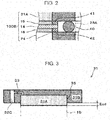
- Fig. 2 is an enlarged diagram of part II in Fig. 1 .
- an electrochemical hydrogen pump 100 of this embodiment includes an electrolyte membrane 14, a cathode catalyst layer 15, an anode catalyst layer 16, a cathode gas diffusion device 31, an anode gas diffusion device 9, a voltage applicator 19, and a fastener 27.
- the cathode gas diffusion device 31 includes a cathode gas diffusion layer 31 A and a cathode separator 31B.
- the anode gas diffusion device 9 includes an anode main body 1 that includes an anode gas diffusion layer 24, an anode gas flow path plate 5, and an anode end plate 10. Specific configurations of the cathode gas diffusion device 31 and the anode gas diffusion device 9 will be described later.
- a unit cell 100A of the electrochemical hydrogen pump 100 includes the electrolyte membrane 14, the cathode catalyst layer 15, the anode catalyst layer 16, the cathode gas diffusion device 31, and the anode gas diffusion device 9.
- the electrochemical hydrogen pump 100 of Fig. 1 configures a stack in which three tiers of the unit cells 100A are laminated.
- the number of tiers of the unit cells 100A is not limited to this. That is, the number of tiers of the unit cells 100A may be set to a proper number based on operation conditions such as the hydrogen amount of the electrochemical hydrogen pump 100.
- the fastener 27 fastens a laminated body 100B of the electrolyte membrane 14, the cathode catalyst layer 15, the anode catalyst layer 16, the cathode gas diffusion layer 31 A, and the anode gas diffusion layer 24.
- an end surface of the cathode gas diffusion device 31 of the uppermost layer of the unit cells 100A and an end surface of the anode gas diffusion device 9 of the lowermost layer are interposed between an end plate 26U and an end plate 26D via insulating plates or the like, which are not illustrated, and a desired fastening pressure has to be thereby exerted on the unit cells 100A.
- the plural fasteners 27 that include a disc spring or the like for exerting the fastening pressure on the unit cells 100A are provided in appropriate positions of the end plate 26U and the end plate 26D.
- the fastener 27 may be in any configuration as long as the fastener 27 may fasten the above laminated body 100B.
- Examples of the fastener 27 may include a bolt that passes through the end plate 26U and the end plate 26D, a nut with a disc spring, and so forth, for example.
- the end plate 26U is provided with a cathode gas lead-out pipe 30 through which cathode gas from the cathode gas diffusion device 31 flows. That is, the cathode gas lead-out pipe 30 communicates with a tubular cathode gas lead-out manifold (not illustrated) that is provided to the unit cell 100A in the laminated state.
- a sealing member such as an O-ring, which is not illustrated, is provided between the cathode gas diffusion device 31 and the anode gas diffusion device 9 so as to surround the cathode gas lead-out manifold, and the cathode gas lead-out manifold is appropriately sealed by the sealing member.
- the end plate 26U is also provided with an anode gas lead-out pipe 29 through which excess anode gas from the anode gas diffusion device 9 flows. That is, the anode gas lead-out pipe 29 communicates with a tubular anode gas lead-out manifold 29A that is provided to the unit cell 100A in a laminated state.
- a sealing member 40 such as an O-ring is provided between the cathode gas diffusion device 31 and the anode gas diffusion device 9 so as to surround the anode gas lead-out manifold 29A, and the anode gas lead-out manifold 29A is appropriately sealed by the sealing member 40.
- the end plate 26D is provided with an anode gas introduction pipe 28 through which the anode gas supplied to the anode gas diffusion device 9 flows. That is, the anode gas introduction pipe 28 communicates with a tubular anode gas introduction manifold 28A that is provided to the unit cell 100A in the laminated state.
- the sealing member 40 such as an O-ring is provided between the cathode gas diffusion device 31 and the anode gas diffusion device 9 so as to surround the anode gas introduction manifold 28A, and the anode gas introduction manifold 28A is appropriately sealed by the sealing member 40.
- the electrolyte membrane 14 includes a pair of main surfaces.
- the electrolyte membrane 14 is a proton-conductive polymer membrane through which protons (H + ) are permeable.
- the electrolyte membrane 14 may be any membrane as long as that is the proton-conductive polymer membrane.
- a fluorine-based polymer electrolyte membrane and so forth may be raised. Specifically, for example, Nafion® (DuPont), AciplexTM (Asahi Kasei Corporation), and so forth may be used.
- the cathode catalyst layer 15 is provided on one main surface (for example, the front surface) of the electrolyte membrane 14. Note that in a planar view, a sealing member 41 such as a gasket is provided so as to surround the cathode catalyst layer 15, and the cathode catalyst layer 15 is appropriately sealed by the sealing member 41.
- the cathode catalyst layer 15 includes platinum as catalyst metal, for example, but embodiments are not limited to this.
- the anode catalyst layer 16 is provided on the other main surface (for example, the back surface) of the electrolyte membrane 14. Note that in a planar view, a sealing member 42 such as a gasket is provided so as to surround the anode catalyst layer 16, and the anode catalyst layer 16 is appropriately sealed by the sealing member 42.
- the anode catalyst layer 16 includes RuIrFeOx as catalyst metal, for example, but embodiments are not limited to this.
- the adjustment methods are not particularly limited.
- electrically-conductive porous substance powder, carbon-based powder, and so forth may be raised.
- carbon-based powder for example, powder of graphite, carbon black, activated carbon that is electrically conductive, or the like may be raised.
- a method for supporting platinum or another catalyst metal on the carrier such as carbon is not particularly limited.
- a method such as powder mixing or liquid-phase mixing may be used.
- a method in which the carrier such as carbon is dispersed in a catalyst component colloid liquid and adsorption is caused or the like may be raised.
- platinum or another catalyst metal may be supported by a method similar to the above method.
- the supported state of the catalyst metal such as platinum on the carrier is not particularly limited.
- the catalyst metal may be atomized and supported on the carrier in a highly dispersed state.
- the voltage applicator 19 applies a voltage between the cathode catalyst layer 15 and the anode catalyst layer 16.
- the voltage applicator 19 may be in any configuration as long as the voltage applicator 19 may apply a voltage between the cathode catalyst layer 15 and the anode catalyst layer 16.
- the voltage applicator 19 may be an instrument that adjusts a voltage applied between the cathode catalyst layer 15 and the anode catalyst layer 16. As the voltage applicator 19, for example, a DC/DC converter, an AC/DC converter, or the like may be raised.
- the DC/DC converter is used in a case where the voltage applicator 19 is connected with a direct current power source such as a battery, and the AC/DC converter is used in a case where the voltage applicator 19 is connected with an alternating current power source such as commercial power source. Further, a low electrical potential side terminal of the voltage applicator 19 is connected with the electrically conductive cathode gas diffusion device 31, and a high electrical potential side terminal of the voltage applicator 19 is connected with the electrically conductive anode gas diffusion device 9.
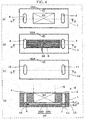
- Fig. 3 is a diagram that illustrates one example of a cathode gas diffusion device of the electrochemical hydrogen pump of the first embodiment.
- the cathode gas diffusion device 31 includes the cathode gas diffusion layer 31 A and the cathode separator 31 B.
- the cathode gas diffusion layer 31A is provided on a main surface of the cathode catalyst layer 15, which does not face the electrolyte membrane 14. Further, the cathode gas diffusion layer 31A may be in any configuration as long as the cathode gas diffusion layer 31A includes desired elasticity, desired electrical conductivity, and desired gas permeability. A specific example of the cathode gas diffusion layer 31 A will be described in a third example.
- the cathode separator 31 B includes a recess portion 35 through which the cathode gas lead out from the cathode gas diffusion layer 31A flows.
- the cathode gas diffusion layer 31A is accommodated in the recess portion 35 and is disposed to project from the recess portion 35 in the thickness direction thereof before fastening of the laminated body 100B by the fastener 27.
- a projection amount Ecd of the cathode gas diffusion layer 31A from the recess portion 35 in the thickness direction is a size that is equal to or larger than the total value of the sizes of the respective compressed thicknesses of the anode gas diffusion layer 24, the anode catalyst layer 16, and the electrolyte membrane 14 in a case of an action of the electrochemical hydrogen pump 100.
- this projection amount Ecd may be equivalent to a compression amount Ecd (thickness) of the cathode gas diffusion layer 31A that is compressed by the fastening force of the laminated body 100B.
- the cathode separator 31 B includes a manifold hole 32C through which the cathode gas flows and a cathode gas flow path 33 that leads out the cathode gas in the recess portion 35 to the manifold hole 32C.
- the cathode gas flow path 33 is configured with a communication hole that causes the manifold hole 32C to communicate with the cathode gas diffusion layer 31A.
- this communication hole may extend from a bottom surface of the recess portion 35 to the manifold hole 32C that is formed in the thickness direction of the cathode separator 31 B.
- the tubular cathode gas lead-out manifold is formed with a manifold hole 32A (see Fig. 4 ) provided to the anode gas diffusion device 9 and the manifold hole 32C.
- the cathode gas may be taken out from the cathode gas diffusion layer 31A in a high pressure state through the cathode gas flow path 33.
- the cathode gas that passes through the cathode gas flow path 33 flows through the cathode gas lead-out manifold and the cathode gas lead-out pipe 30 in this order.
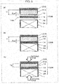
- Fig. 4 is a diagram that illustrates one example of an anode gas diffusion device of the electrochemical hydrogen pump of the first embodiment.
- Fig. 4(a) is a diagram of the anode main body 1 of the anode gas diffusion device 9 in a planar view.
- Fig. 4(b) is a diagram of the anode gas flow path plate 5 of the anode gas diffusion device 9 in a planar view.
- Fig. 4(c) is a diagram of the anode end plate 10 of the anode gas diffusion device 9 in a planar view.
- Fig. 4(d) is a cross-sectional diagram of the anode gas diffusion device 9. That is, Fig. 4(d) illustrates the cross section of the anode gas diffusion device 9 that corresponds to part D-D in a case where members that are illustrated in Fig. 4(a), Fig. 4(b), and Fig. 4(c) in a planar view are laminated.
- the anode gas diffusion device 9 includes the anode main body 1, the anode gas flow path plate 5, and the anode end plate 10.
- the anode main body 1 is a metallic member that diffuses the anode gas.
- the anode main body 1 may be in any configuration as long as the anode main body 1 is a metallic member that diffuses the anode gas.
- the anode main body 1 may be configured with metal such as stainless steel, titanium, a titanium alloy, or an aluminum alloy, for example.
- the thickness of the anode main body 1 may be approximately several hundred ⁇ m (for example, approximately 400 ⁇ m). Those materials and values are examples, and embodiments are not limited to those examples.
- the anode main body 1 includes the anode gas diffusion layer 24, a manifold hole 3 for anode gas introduction, and a manifold hole 4 for leading the anode gas out.
- the anode gas diffusion layer 24 is configured to be capable of diffusing the anode gas by using a laminated body of metal plates that include through holes, a sintered body of metal powder in a porous structure, or the like.
- the anode gas flow path plate 5 is provided on the main surface of the anode main body 1.
- the anode gas flow path plate 5 is provided to make surface contact with the main surface of the anode main body 1.
- anode gas flow path plate 5 As a material of the anode gas flow path plate 5, stainless steel, titanium, a titanium alloy, an aluminum alloy, or the like may be used, for example.
- the thickness of the anode gas flow path plate 5 may be approximately several ten ⁇ m (for example, approximately 50 ⁇ m). Those materials and values are examples, and embodiments are not limited to those examples.
- the anode gas flow path plate 5 includes a manifold hole 7 for anode gas introduction, a manifold hole 8 for leading anode gas out, and an anode gas flow path 6.
- the manifold hole 7 and the manifold hole 8 are arranged to be respectively opposed to the manifold hole 3 and the manifold hole 4 of the anode main body 1.
- the anode gas flow path 6 of the anode gas flow path plate 5 is configured with plural slit holes 36D that communicate with the manifold hole 7 and linearly extend toward the manifold hole 8 but do not communicate with the manifold hole 8 and plural slit holes 36U that communicate with the manifold hole 8 and linearly extend toward the manifold hole 7 but do not communicate with the manifold hole 7. That is, the anode gas flow path plate 5 is formed by integrally joining a first metal layer 5D that includes the slit holes 36D and a second metal layer 5U that includes the slit holes 36U such that those slit holes 36D and slit holes 36U overlap with each other.
- the manifold hole 7 communicates with a plurality of one ends of the anode gas flow path 6 and is thereby used for anode gas introduction to the anode gas diffusion layer 24. That is, the anode gas that passes through a contact portion between the slit holes 36 of the anode gas flow path 6 and the anode gas diffusion layer 24 is delivered to the anode gas diffusion layer 24.
- the manifold hole 8 communicates with a plurality of the other ends of the anode gas flow path 6 and is thereby used for leading anode gas out from the anode gas diffusion layer 24.
- the anode end plate 10 is provided on the main surface (hereinafter referred to as an opposite surface), which does not face the anode main body 1, of the main surfaces of the anode gas flow path plate 5. Specifically, the plural slit holes 36 of the anode gas flow path plate 5 are covered from the opposite surface by the anode end plate 10.
- anode end plate 10 As a material of the anode end plate 10, stainless steel, titanium, a titanium alloy, an aluminum alloy, or the like may be used, for example.
- the thickness of the anode end plate 10 may be approximately several ten ⁇ m (for example, approximately 50 ⁇ m). Those materials and values are examples, and embodiments are not limited to those examples.
- the anode end plate 10 includes a manifold hole 11 for anode gas introduction and a manifold hole 12 for leading anode gas out.
- the manifold hole 11 and the manifold hole 12 of the anode end plate 10 are arranged to be respectively opposed to the manifold hole 7 and the manifold hole 8 of the anode gas flow path plate 5.
- the anode gas introduction manifold 28A is formed with the manifold hole 11, the manifold hole 7, the manifold hole 3, and the manifold hole of the cathode gas diffusion device 31.
- the anode gas lead-out manifold 29A is formed with the manifold hole 12, the manifold hole 8, the manifold hole 4, and the manifold hole of the cathode gas diffusion device 31.
- the anode end plate 10, the anode gas flow path plate 5, and the anode main body 1 may be integrally bonded by metal joining by welding, soldering, deposition, or the like.
- surface joining by diffusion joining or the like may be performed for the main surface of the anode end plate 10, the main surface of the anode gas flow path plate 5, and a main surface of the anode main body 1. Accordingly, compared to a case where the anode end plate 10, the anode gas flow path plate 5, and the anode main body 1 are laminated by fixing by a mechanical fastening member, gaps do not remain in the respective joining portions, and the contact resistance (electric resistance) of the anode gas diffusion device 9 may thus be reduced. Then, an increase in power consumption requested for the electrochemical hydrogen pump 100 in a case where a desired voltage is applied to the anode gas diffusion device 9 may be inhibited.
- Fig. 5 is a diagram that illustrates one example of a fastening action of a unit cell of the electrochemical hydrogen pump of the first embodiment.
- FIG. 5 illustrates cross-sections of the cathode separator 31 B, the cathode gas diffusion layer 31 A, a member in which the cathode catalyst layer 15 and the anode catalyst layer 16 are respectively coated onto the main surfaces of the electrolyte membrane 14 (hereinafter referred to as an electrolyte membrane (with catalyst layers) 14A), the anode gas diffusion layer 24, and the anode main body 1.
- position adjustment is performed such that the cathode gas diffusion layer 31A is opposed to the electrolyte membrane (with catalyst layers) 14A and the electrolyte membrane (with catalyst layers) 14A is opposed to the anode gas diffusion layer 24.
- the cathode gas diffusion layer 31 A, the electrolyte membrane (with catalyst layers) 14A, and the anode gas diffusion layer 24 are laminated.
- the cathode gas diffusion layer 31A, the electrolyte membrane (with catalyst layers) 14A, and the anode gas diffusion layer 24 are brought into contact, the fastening force by the fastener 27 is not exerted.
- the gap that is correspondent to the projection amount Ecd in the thickness direction of the cathode gas diffusion layer 31A is formed between the main surface of the cathode separator 31 B and the electrolyte membrane (with catalyst layers) 14A.
- the fastening of the laminated body 100B by the fastener 27 is performed.
- the cathode gas diffusion layer 31 A is compressed by the fastening force of the fastener 27, and the cathode gas diffusion layer 31 A, the electrolyte membrane (with catalyst layers) 14A, and the anode gas diffusion layer 24 are brought into tight contact.
- the compression amount (thickness) of the cathode gas diffusion layer 31 A is equivalent to the above projection amount Ecd.
- the value that results from the subtraction of a thickness T2 at a time after compression of the cathode gas diffusion layer 31A from a thickness T1 at a time before the compression of the cathode gas diffusion layer 31A is equivalent to the above projection amount Ecd.
- the controller may be in any configuration as long as the controller has a control function.
- the controller includes an arithmetic circuit and a storage circuit that stores the control program, for example.
- Examples of the arithmetic circuit may include an MPU, a CPU, and so forth, for example.
- Examples of the storage circuit may include a memory, for example.
- the controller may be configured with a single controller that performs centralized control or may be configured with plural controllers that mutually and cooperatively perform distributed control.
- the voltage applicator 19 applies a voltage between the cathode gas diffusion device 31 and the anode gas diffusion device 9.
- the anode gas is supplied to the anode gas diffusion device 9. Specifically, the anode gas is supplied from the anode gas introduction pipe 28 to the manifold hole 7 in Fig. 4 . Then, because the manifold hole 7 communicates with one ends of the anode gas flow path 6 of the anode gas flow path plate 5, the gas is delivered from the manifold hole 7 to the anode gas flow path 6.
- anode gas diffusion layer 24 includes a gas diffusion function
- the anode gas that flows from the anode gas flow path 6 toward the main surface (hereinafter referred to as an opposite surface) of the anode gas diffusion layer 24, which does not face the anode gas flow path plate 5, may pass through the opposite surface while being uniformly diffused by the anode gas diffusion layer 24. Accordingly, the anode gas is uniformly supplied to the anode catalyst layer 16 that is arranged on the opposite surface of the anode gas diffusion layer 24.
- excess anode gas that does not pass through the above opposite surface is delivered to the manifold hole 8 that communicates with the other ends of the anode gas flow path 6 of the anode gas flow path plate 5 and is discharged to the anode gas lead-out pipe 29.
- the anode gas for example, reformed gas containing hydrogen, hydrogen-containing gas that is generated by water electrolysis, or the like may be raised.
- a proton permeates the inside of the electrolyte membrane 14 while accompanying a water molecule and moves to the cathode catalyst layer 15.
- the cathode catalyst layer 15 the reduction reaction of the proton that permeates the electrolyte membrane 14 and an electron takes place, and the cathode gas (hydrogen gas) is thereby generated (formula (2)).
- purification of hydrogen gas is highly efficiently performed from the hydrogen gas (anode gas) that contains impurities such as CO 2 gas.
- the anode gas may contain CO gas as an impurity.
- CO gas lowers catalyst activities of the anode catalyst layer 16 and so forth, it is desirable that CO gas is removed by a CO remover (for example, a transformer, a CO selective oxidizer, or the like), which is not illustrated.
- a pressure drop of the cathode gas lead-out pipe 30 is increased, a voltage E of the voltage applicator 19 is raised, and a gas pressure P2 of a cathode thereby becomes a high pressure.
- the relationship among a gas pressure P1 of an anode, a gas pressure P2 of a cathode, and the voltage E of the voltage applicator 19 is formulated by the following formula (3).
- R represents the gas constant (8.3145 J/K ⁇ mol)
- T represents a temperature (K)
- F represents the Faraday constant (96485 C/mol)
- P2 represents the gas pressure of the cathode
- P1 represents the gas pressure of the anode
- i current density (A/cm 2 )
- r represents a cell resistance ( ⁇ cm 2 ).
- the voltage E of the voltage applicator 19 is raised and the gas pressure P2 of the cathode may thereby be caused to rise.
- the pressure drop of the cathode gas lead-out pipe 30 may be increased or decreased in accordance with the opening degree of a switch valve that is provided to the cathode gas lead-out pipe 30, for example.
- the pressure drop of the cathode gas lead-out pipe 30 is decreased (for example, the opening degree of the switch valve is made higher), and the cathode gas of the cathode gas diffusion device 31 is thereby filled in a high-pressure hydrogen tank, which is not illustrated, through the cathode gas lead-out pipe 30.
- the pressure drop of the cathode gas lead-out pipe 30 is increased (for example, the opening degree of the switch valve is made lower), and the cathode gas diffusion device 31 is thereby disconnected from the high-pressure hydrogen tank. Accordingly, the reverse flow of the cathode gas of the high-pressure hydrogen tank to the cathode gas diffusion device 31 is inhibited.
- the cathode gas (hydrogen gas) of high purity is pressurized to a desired target pressure and is filled in the high-pressure hydrogen tank by the electrochemical hydrogen pump 100.
- the cathode gas diffusion layer 31A is configured to project by the projection amount Ecd in the thickness direction from the recess portion 35 of the cathode separator 31 B before the fastening of the laminated body 100B by the fastener 27. Further, as illustrated in Fig. 5(c) , the cathode gas diffusion layer 31A is compressed by the projection amount Ecd by the fastener 27 during the fastening of the laminated body 100B.
- the above projection amount Ecd (the compressed thickness of the cathode gas diffusion layer 31A) is set such that the relationship expressed by the following formula (5) holds between the projection amount Ecd and the total value Eat of formula (4).
- the thickness T1 of the cathode gas diffusion layer 31A at a time before the fastening of the laminated body 100B is set such that the size of the compressed thickness of the cathode gas diffusion layer 31A (in this example, the projection amount Ecd) in a case of the fastening of the laminated body 100B is equal to or larger than the total value Eat of the sizes of the respective compressed thicknesses of the anode gas diffusion layer 24, the anode catalyst layer 16, and the electrolyte membrane 14 in a case of the action of the electrochemical hydrogen pump 100.
- Ecd ⁇ Em + Eac + Ead Eat
- the electrochemical hydrogen pump 100 of this embodiment may simply and appropriately inhibit an increase in the contact resistance between the cathode catalyst layer 15 and the cathode gas diffusion layer 31A compared to related art.
- the cathode gas of the electrochemical hydrogen pump 100 becomes a high pressure state in a case of the action of the electrochemical hydrogen pump 100
- the cathode gas may not pass through the electrolyte membrane 14, and a high pressure is thus exerted on the electrolyte membrane 14, the anode catalyst layer 16, and the anode gas diffusion layer 24. Then, each of the electrolyte membrane 14, the anode catalyst layer 16, and the anode gas diffusion layer 24 is compressed and deformed.
- the cathode gas diffusion layer 31A elastically deforms in the direction in which the cathode gas diffusion layer 31A is recovered from the compressed thickness T2 by the fastener 27 to the uncompressed and original thickness T1, and the contact between the cathode catalyst layer 15 and the cathode gas diffusion layer 31A may thereby be maintained appropriately.
- a dedicated member for pressing the cathode gas diffusion layer 31 A to the cathode catalyst layer 15 is not requested, the above increase in the contact resistance may be inhibited by a simpler configuration than the techniques disclosed in Japanese Unexamined Patent Application Publication No. 2006-70322 .
- the size of the compressed thickness of the cathode gas diffusion layer 31A in a case of the fastening of the laminated body 100B is decided in consideration of the total value Eat of the sizes of the respective compressed thicknesses of the anode gas diffusion layer 24, the anode catalyst layer 16, and the electrolyte membrane 14 in a case of the action of the electrochemical hydrogen pump 100.
- the above increase in the contact resistance may be inhibited more appropriately than the techniques disclosed in Japanese Unexamined Patent Application Publication No. 2006-111924 .
- the electrochemical hydrogen pump 100 of this embodiment may inhibit the increase in the voltage E applied by the voltage applicator 19 and may further inhibit lowering of the operation efficiency of the electrochemical hydrogen pump 100.
- a stable operation of the electrochemical hydrogen pump 100 may be performed.
- a compression amount Em (thickness) of the electrolyte membrane 14, a compression amount Eac (thickness) of the anode catalyst layer 16, and a compression amount Ead (thickness) of the anode gas diffusion layer 24 change in accordance with configuration materials, initial thicknesses at a time before compression and deformation, and so forth of those.
- the above values also change in accordance with the magnitude of the gas pressure P2 of the cathode in a case of the operation of the electrochemical hydrogen pump 100.
- the fastening force of the laminated body 100B has to exercise a compression force for compressing the cathode gas diffusion layer 31A by at least the projection amount Ecd.
- the cathode gas diffusion layer 31A has higher rigidity on the side that faces the cathode separator 31 B than the side that corresponds to the cathode catalyst layer 15.
- the fastening force of the laminated body 100B is exerted on the cathode gas diffusion layer 31A through the above cathode separator 31B.
- the rigidity of the cathode gas diffusion layer 31 A on the side that faces the cathode separator 31 B is made higher than that on the side that corresponds to the cathode catalyst layer 15, and it is thereby possible that the fastening force is uniformly exerted on the cathode gas diffusion layer 31A compared to the opposite case.
- the cathode gas diffusion layer 31A and the cathode catalyst layer 15 may be brought into contact at a uniform pressure, the increase in the contact resistance between the cathode catalyst layer 15 and the cathode gas diffusion layer 31A may be inhibited further effectively.
- the increase and decrease in the rigidity of the cathode gas diffusion layer 31A may be adjusted by the density of the sintered metal fiber body. That is, in the electrochemical hydrogen pump 100 of this example, the density of the sintered metal fiber body on the side that faces the cathode separator 31 B is higher than the density of the sintered metal fiber body on the side that corresponds to the cathode catalyst layer 15.
- the rigidity which is mentioned here, is correspondent to the flexural rigidity of the cathode gas diffusion layer 31A.
- This flexural rigidity may be known by measuring the Young's modulus of the cathode gas diffusion layer 31A by a static test method (bending test), a transverse vibration method, an ultrasonic method, or the like.
- the electrochemical hydrogen pump 100 of this example may be configured similarly to the electrochemical hydrogen pump 100 of the first embodiment.
- the cathode gas diffusion layer 31A has higher porosity on the side that faces the cathode catalyst layer 15 than the side that corresponds to the cathode separator 31 B.
- the gas permeability of the cathode gas diffusion layer 31A becomes higher.
- the cathode gas is easily drawn from the cathode catalyst layer 15 into the cathode gas diffusion layer 31A compared to the opposite case.
- the porosity of the cathode gas diffusion layer 31A becomes higher, the cathode gas diffusion layer 31A is more easily crushed.
- the tightness of contact between the cathode catalyst layer 15 and the cathode gas diffusion layer 31A may be improved compared to the opposite case.
- the increase and decrease in the porosity of the cathode gas diffusion layer 31A may be adjusted by the density of the sintered metal fiber body. That is, in the electrochemical hydrogen pump 100 of this example, the density of the sintered metal fiber body on the side that corresponds to the cathode catalyst layer 15 is lower than the density of the sintered metal fiber body on the side that faces the cathode separator 31 B.
- the porosity of the cathode gas diffusion layer 31A may be represented by air permeability that may be measured by a Gurley tester method or the like, for example.
- the electrochemical hydrogen pump 100 of this example may be configured similarly to the electrochemical hydrogen pump 100 of the first embodiment.
- the cathode gas diffusion layer 31A is configured with a sintered body of metal fiber.
- the cathode gas diffusion layer 31A is configured with the sintered body of metal fiber, and it thereby becomes easy to secure elasticity and gas permeability that are requested for the cathode gas diffusion layer 31A compared to a case where the cathode gas diffusion layer 31A is configured with a metal steel plate provided with plural vent holes.
- the cathode gas diffusion layer 31A has to be an elastic body that is recovered from the compressed thickness T2 by the fastening force of the fastener 27 to the uncompressed and original thickness T1. Further, in view of reduction in the contact resistance between the cathode catalyst layer 15 and the cathode gas diffusion layer 31 A, it is better for the cathode gas diffusion layer 31A to have high electrical conductivity.
- the cathode gas diffusion layer 31A may be configured with a sintered body of metal fiber, which is a sintered body of titanium fiber in a non-woven fabric form and applying platinum plating to the surface thereof, for example.
- the metal fibers are configured in a three-dimensional manner, and mutual connection points are sintered. Accordingly, the electrical conductivity of this sintered metal fiber body is high. Further, because the metal fibers are configured in a three-dimensional manner, the gas dispersion performance of this sintered metal fiber body is high.
- a material that is configured with graphitized carbon fiber is carbon particles which are coated with an ionically conductive resin, kneaded into a rubber form, and processed into a sheet shape, has elasticity like the above sintered metal fiber body in a non-woven fabric form, and has high electrical conductivity may be used as a cathode gas diffusion layer.
- the cathode gas diffusion layer 31A it is better to use a material in which the change in the electrical conductivity of the cathode gas diffusion layer 31A is small with respect to the compression amount (thickness). For example, as the compression amount (thickness) of the cathode gas diffusion layer 31A becomes larger, the intervals among configuration members of the cathode gas diffusion layer 31A become shorter. Further, the contact areas among the configuration members of the cathode gas diffusion layer 31A increase. Thus, as the compression amount (thickness) of the cathode gas diffusion layer 31A becomes larger, the electric resistance of the cathode gas diffusion layer 31A tends to become lower.
- the compression amount (thickness) of the cathode gas diffusion layer 31A is different between a case where the electrochemical hydrogen pump 100 operates and a case where the operation stops. Further, in the operation of the electrochemical hydrogen pump 100, the gas pressure P2 of the cathode of the electrochemical hydrogen pump 100 changes from a low pressure to a high pressure. Then, the compression amount (thickness) of the cathode gas diffusion layer 31A also changes. Thus, as described above, for the stable operation of the electrochemical hydrogen pump 100, it is better to use a material, in which the change in the electric resistance (electrical conductivity) of the cathode gas diffusion layer 31A is small with respect to the change in the compression amount (thickness), for the cathode gas diffusion layer 31A.
- the electrochemical hydrogen pump 100 of this example may be configured similarly to the electrochemical hydrogen pump 100 of any of the first embodiment and the first example and the second example of the first embodiment.
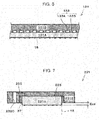
- Fig. 6 is a diagram that illustrates one example of a cathode gas diffusion device of the electrochemical hydrogen pump of a first modification example of the first embodiment.
- a cathode gas diffusion device 131 includes a cathode gas diffusion layer 131A and a cathode separator 131B.
- the cathode gas diffusion layer 131A is similar to the cathode gas diffusion layer 31A of the first embodiment, and a description will thus not be made.
- the cathode separator 31 B includes the recess portion 35 through which the cathode gas led out from the cathode gas diffusion layer 31A flows.
- a configuration of a cathode separator is not limited to this.
- the cathode separator 131 B includes a manifold hole, which is not illustrated, and a cathode gas flow path 133 that communicates with this manifold hole.
- the cathode gas flow path 133 is configured with a groove portion 133A and a rib 133B that are formed on a main surface of the cathode separator 131 B. Note that in a case where the unit cells 100A are laminated, the tubular cathode gas lead-out manifold is formed with the manifold hole 32A (see Fig. 4 ) provided to the anode gas diffusion device 9 and the manifold hole of the cathode separator 131 B, which is not illustrated.
- the cathode gas may be taken out from the cathode gas diffusion layer 131A in a high pressure state through the groove portion 133A of the cathode gas flow path 133.
- the cathode gas that passes through the groove portion 133A flows through the cathode gas lead-out manifold and the cathode gas lead-out pipe 30 in this order.
- the electrochemical hydrogen pump 100 of this modification example may be configured similarly to the electrochemical hydrogen pump 100 of any of the first embodiment and the first example to the third example of the first embodiment.
- Fig. 7 is a diagram that illustrates one example of a cathode gas diffusion device of the electrochemical hydrogen pump of a second modification example of the first embodiment.
- a cathode gas diffusion device 231 includes a cathode gas diffusion layer 231A, a cathode separator 231B, and an elastic member 37.
- the cathode separator 231 B includes a recess portion 235 through which the cathode gas led out from the cathode gas diffusion layer 231A flows. Note that the cathode gas diffusion layer 231 A is similar to the cathode gas diffusion layer 31A of the first embodiment, and a description will thus not be made.
- the elastic member 37 is provided between a side surface of the cathode gas diffusion layer 231A and a side surface of the recess portion 235 of the cathode separator 231 B.
- the elastic member 37 may be formed into an annular shape (for example, a rectangularly annular shape or a circularly annular shape) along a side surface of the cathode gas diffusion layer 231A in an annular shape (for example, a rectangularly annular shape or a circularly annular shape) in a planar view of the cathode gas diffusion device 231.
- the dimension of the elastic member 37 in the central axis direction may be shorter than the thickness of the cathode gas diffusion layer 231A.
- the dimension of the elastic member 37 in the central axis direction may be substantially the same as the depth of the recess portion 235 of the cathode separator 231 B as illustrated in Fig. 7 .
- the cathode separator 231 B includes a manifold hole 232C through which the cathode gas flows and a cathode gas flow path 233 that leads out the cathode gas in the recess portion 235 to the manifold hole 232C.
- the cathode gas flow path 233 is configured with a communication hole that causes the manifold hole 232C to communicate with the cathode gas diffusion layer 231A.
- this communication hole may extend from a bottom surface of the recess portion 235, which is not provided with the elastic member 37, to the manifold hole 232C that is formed in the thickness direction of the cathode separator 231 B.
- the tubular cathode gas lead-out manifold is formed with the manifold hole 32A (see Fig. 4 ) provided to the anode gas diffusion device 9 and the manifold hole 232C.
- the cathode gas may be taken out from the cathode gas diffusion layer 231A in a high pressure state through the cathode gas flow path 233 of the cathode separator 231 B.
- the cathode gas that passes through the cathode gas flow path 233 flows through the cathode gas lead-out manifold and the cathode gas lead-out pipe 30 in this order.
- the electrochemical hydrogen pump 100 of this modification example may simply and appropriately inhibit an increase in a contact resistance between the cathode catalyst layer 15 and the cathode gas diffusion layer 231A compared to related art.
- a main surface of the cathode gas diffusion layer 231A tightly contacts with the main surface of the cathode catalyst layer 15 in the fastening, and the cathode gas diffusion layer 231A is thereby compressed by the fastening pressure in the vertical direction to the main surface (thickness direction) but is stretched in the parallel direction with this main surface.
- the cathode gas diffusion layer 231A projects from the recess portion 235 in a periphery of the recess portion 235 of the cathode separator 231 B, and this projecting portion possibly causes damage to the cathode catalyst layer 15 or the electrolyte membrane 14.
- the elastic member 37 is provided between the side surface of the cathode gas diffusion layer 231 A and the side surface of the recess portion 235, the stretch of the cathode gas diffusion layer 231A in the parallel direction with the main surface of the cathode gas diffusion layer 231A is thereby absorbed, and the possibility that the cathode gas diffusion layer 231A projects from the recess portion 235 in the periphery of the recess portion 235 may thereby be reduced.
- the elastic member 37 may be any member as long as the elastic member 37 is a member that may absorb the stretch of the cathode gas diffusion layer 231A in the parallel direction with the main surface of the cathode gas diffusion layer 231A.
- the elastic member 37 is configured with a material whose rigidity is lower than the cathode gas diffusion layer 231A.
- rubber, a porous resin, or the like may be used, for example.
- embodiments are not limited to these.
- the above elastic member 37 may be provided to the electrochemical hydrogen pump 100 of any of the first embodiment, the first example to the third example of the first embodiment, and the first modification example of the first embodiment. That is, except for the above features, the electrochemical hydrogen pump 100 of this modification example may be configured similarly to the electrochemical hydrogen pump 100 of any of the first embodiment, the first example to the third example of the first embodiment, and the first modification example of the first embodiment.
- Fig. 8 and Fig. 9 are diagrams that illustrate examples of an electrochemical hydrogen pump of a second embodiment.
- Fig. 9 is an enlarged diagram of part IX in Fig. 8 .
- the electrochemical hydrogen pump 100 of this embodiment includes the electrolyte membrane 14, the cathode catalyst layer 15, the anode catalyst layer 16, the cathode gas diffusion device 31, the anode gas diffusion device 9, the voltage applicator 19, and the fastener 27.
- the cathode gas diffusion device 31 includes the cathode gas diffusion layer 31A and the cathode separator 31 B.
- the anode gas diffusion device 9 includes the anode main body 1 that includes the anode gas diffusion layer 24, the anode gas flow path plate 5, and the anode end plate 10.
- the unit cell 100A of the electrochemical hydrogen pump 100 includes the electrolyte membrane 14, the cathode catalyst layer 15, the anode catalyst layer 16, the cathode gas diffusion device 31, and the anode gas diffusion device 9.
- the electrochemical hydrogen pump 100 of Fig. 8 configures a stack in which three tiers of the unit cells 100A are laminated.
- the number of tiers of the unit cells 100A is not limited to this. That is, the number of tiers of the unit cells 100A may be set to a proper number based on operation conditions such as the hydrogen amount of the electrochemical hydrogen pump 100.
- the fastener 27 fastens the laminated body 900B of the electrolyte membrane 14, the cathode catalyst layer 15, the anode catalyst layer 16, the cathode gas diffusion layer 31 A, and the anode gas diffusion layer 24.
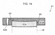
- Fig. 10 is a diagram that illustrates one example of a cathode gas diffusion device of the electrochemical hydrogen pump of the second embodiment.
- the cathode gas diffusion device 31 includes the cathode gas diffusion layer 31A and the cathode separator 31 B.
- the cathode gas diffusion layer 31A is provided on a main surface of the cathode catalyst layer 15, which does not face the electrolyte membrane 14. Further, the cathode gas diffusion layer 31A may be in any configuration as long as the cathode gas diffusion layer 31A includes desired elasticity, desired electrical conductivity, and desired gas permeability. A specific example of the cathode gas diffusion layer 31A will be described in a fifth example.
- the cathode separator 31 B includes the recess portion 35 through which the cathode gas lead out from the cathode gas diffusion layer 31A flows.
- the recess portion 35 is not provided with a partition portion (rib) for partitioning the flow of the cathode gas in the recess portion 35.
- rib partition portion
- the bottom surface of the recess portion 35 of the cathode separator 31 B includes a protrusion portion 35T that does not partition the flow of the cathode gas.
- the bottom surface of the recess portion 35 may be in any configuration as long as the bottom surface includes the protrusion portion 35T that does not partition the flow of the cathode gas.
- the protrusion portion 35T may be provided such that the center of the bottom surface of the recess portion 35 becomes highest.
- the protrusion portion 35T may be configured to swell from a peripheral portion of the bottom surface of the recess portion 35 to a distance Tcd in the perpendicular direction in a curved surface shape (bowl shape).
- Processing of the curved surface of such a protrusion portion 35T may be performed by machining of the bottom surface of the recess portion 35 of the cathode separator 31 B, for example.
- plural thin metal membranes whose areas gradually become smaller may be laminated, and a protrusion portion may thereby be formed.
- the distance Tcd of the protrusion portion may easily be adjusted by the thickness of the thin metal membrane.
- the protrusion portion may simply be formed only by laminating the thin metal membranes.
- the cathode gas diffusion layer 31A is accommodated in the recess portion 35 and is disposed to project from the recess portion 35 in the thickness direction thereof before fastening of the laminated body 100B by the fastener 27.
- the cathode gas diffusion layer 31A is configured with an elastic material, the main surface of the cathode gas diffusion layer 31A that faces the protrusion portion 35T elastically deforms along the shape of the protrusion portion 35T from a flat surface. Then, a main surface of the cathode gas diffusion layer 31A on the opposite side that does not face the protrusion portion 35T also elastically deforms from a flat surface into a similar shape to the protrusion portion 35T and protrudes in the perpendicular direction.
- the projection amount Ecd of the cathode gas diffusion layer 31A from the recess portion 35 in the thickness direction is a size that is equal to or larger than the total value of the sizes of the respective compressed thicknesses of the anode gas diffusion layer 24, the anode catalyst layer 16, and the electrolyte membrane 14 in a case of the action of the electrochemical hydrogen pump 100.
- this projection amount Ecd may be equivalent to the compression amount Ecd (thickness) of the central portion of the cathode gas diffusion layer 31A that is compressed by the fastening force of the laminated body 100B.
- Fig. 11 is a diagram that illustrates one example of an anode gas diffusion device of the electrochemical hydrogen pump of the second embodiment.
- Fig. 11 (a) is a diagram of the anode main body 1 of the anode gas diffusion device 9 in a planar view.
- Fig. 11 (b) is a diagram of the anode gas flow path plate 5 of the anode gas diffusion device 9 in a planar view.
- Fig. 11 (c) is a diagram of the anode end plate 10 of the anode gas diffusion device 9 in a planar view.
- Fig. 11(d) is a cross-sectional diagram of the anode gas diffusion device 9. That is, Fig. 11 (d) illustrates the cross section of the anode gas diffusion device 9 that corresponds to part D-D in a case where members that are illustrated in Fig. 11 (a), Fig. 11 (b), and Fig. 11(c) in a planar view are laminated.
- the configuration of the anode gas diffusion device 9 of the electrochemical hydrogen pump 100 of the second embodiment is similar to the configuration of the anode gas diffusion device 9 of the electrochemical hydrogen pump 100 of the first embodiment, and a description will thus not be made.
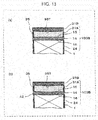
- Fig. 12 is a diagram that illustrates one example of a fastening action of a unit cell of the electrochemical hydrogen pump of the second embodiment.
- FIG. 12 illustrates cross-sections of the cathode separator 31 B, the cathode gas diffusion layer 31A, a member in which the cathode catalyst layer 15 and the anode catalyst layer 16 are respectively coated onto the main surfaces of the electrolyte membrane 14 (hereinafter referred to as the electrolyte membrane (with catalyst layers) 14A), the anode gas diffusion layer 24, and the anode main body 1.
- position adjustment is performed such that the cathode gas diffusion layer 31A is opposed to the electrolyte membrane (with catalyst layers) 14A and the electrolyte membrane (with catalyst layers) 14A is opposed to the anode gas diffusion layer 24.
- the cathode gas diffusion layer 31A, the electrolyte membrane (with catalyst layers) 14A, and the anode gas diffusion layer 24 are laminated.
- the fastening force by the fastener 27 is not exerted.
- the peripheral portion of the cathode gas diffusion layer 31 A is separated from the electrolyte membrane (with catalyst layers) 14A, and the gap that is correspondent to the projection amount Ecd in the thickness direction of the cathode gas diffusion layer 31A is formed between the main surface of the cathode separator 31 B and the electrolyte membrane (with catalyst layers) 14A.
- the fastening of the laminated body 100B by the fastener 27 is performed.
- the cathode gas diffusion layer 31A is compressed by the fastening force of the fastener 27, and the cathode gas diffusion layer 31A, the electrolyte membrane (with catalyst layers) 14A, and the anode gas diffusion layer 24 are brought into tight contact.
- the compression amount (thickness) of the cathode gas diffusion layer 31 A is equivalent to the above projection amount Ecd in the central portion and is smaller than the central portion by about the distance Tcd (see Fig. 10 ) in the peripheral portion.
- the value that results from the subtraction of the thickness T2 at a time after compression of the central portion from the original thickness T1 at a time before the compression of the central portion of the cathode gas diffusion layer 31A is equivalent to the above projection amount Ecd.
- the action (operation) of the electrochemical hydrogen pump 100 of the second embodiment is similar to the action (operation) of the electrochemical hydrogen pump 100 of the first embodiment, and a description will thus not be made.
- the central portion of the cathode gas diffusion layer 31A is configured to project by the projection amount Ecd in the thickness direction from the recess portion 35 of the cathode separator 31 B before the fastening of the laminated body 100B by the fastener 27. Further, as illustrated in Fig. 12(c) , the central portion of the cathode gas diffusion layer 31A is compressed by the projection amount Ecd by the fastener 27 during the fastening of the laminated body 100B.
- the above projection amount Ecd (the compressed thickness of the central portion of the cathode gas diffusion layer 31A) is set such that the relationship expressed by the following formula (5) holds between the projection amount Ecd and the total value Eat of formula (4).
- the thickness T1 of the cathode gas diffusion layer 31A at a time before the fastening of the laminated body 100B is set such that the size of the compressed thickness of the cathode gas diffusion layer 31A (in this example, the projection amount Ecd) in a case of the fastening of the laminated body 100B is equal to or larger than the total value Eat of the sizes of the respective compressed thicknesses of the anode gas diffusion layer 24, the anode catalyst layer 16, and the electrolyte membrane 14 in a case of the action of the electrochemical hydrogen pump 100.
- Ecd ⁇ Em + Eac + Ead Eat
- the electrochemical hydrogen pump 100 of this embodiment may simply and appropriately inhibit an increase in the contact resistance between the cathode catalyst layer 15 and the cathode gas diffusion layer 31A compared to related art.
- the cathode gas diffusion layer 31A elastically deforms in the direction in which the cathode gas diffusion layer 31A is recovered from the compressed thickness T2 by the fastener 27 to the uncompressed and original thickness T1, and the contact between the cathode catalyst layer 15 and the cathode gas diffusion layer 31A may thereby be maintained appropriately.
- the above increase in the contact resistance may be inhibited by a simpler configuration than the techniques disclosed in Japanese Unexamined Patent Application Publication No. 2006-70322 .
- Fig. 13 deformation of the electrolyte membrane 14, the anode catalyst layer 16, and the anode gas diffusion layer 24 that occurs in a high pressure state of the cathode gas of the electrochemical hydrogen pump 100 in a case of the action of the electrochemical hydrogen pump 100 does not become uniform in the planes of those.
- Fig. 13(a) illustrates a cross section of the laminated body 100B at a time before the pressurization action of the cathode gas of the electrochemical hydrogen pump 100.
- Fig. 13(b) illustrates a cross section of the laminated body 100B in the pressurization action of the cathode gas of the electrochemical hydrogen pump 100.
- the compression amount (thickness) of a peripheral portion of the anode gas diffusion layer 24 in the vicinity of the anode main body 1 is smaller than the compression amount (thickness) of a central portion due to the rigidity of the anode main body 1.
- the sealing member 42 for example, a gasket or the like
- the compression amounts (thicknesses) of the peripheral portions of the anode catalyst layer 16 in the vicinity of the sealing member 42 and the electrolyte membrane 14 are smaller than the compression amounts (thicknesses) of central portions due to the rigidity of the sealing member 42.
- the thickness of the cathode gas diffusion layer 31A at a time after the elastic deformation in the direction in which the cathode gas diffusion layer 31A is recovered from the compressed thickness by the fastener 27 to the uncompressed thickness is thick in the central portion compared to the peripheral portion. Then, because the contact pressure between the cathode catalyst layer 15 and the cathode gas diffusion layer 31A is low in central portions compared to peripheral portions, the contact resistance between both of those possibly becomes non-uniform in the plane.
- the bottom surface of the recess portion 35 of the cathode separator 31 B includes the protrusion portion 35T, the above thickness of the cathode gas diffusion layer 31A at a time after the elastic deformation may thereby be made uniform in the plane, and such a possibility may thereby be reduced. That is, the increase in the contact resistance between the cathode catalyst layer 15 and the cathode gas diffusion layer 31A may more appropriately be inhibited than the techniques disclosed in Japanese Unexamined Patent Application Publication No. 2006-111924 .
- the electrochemical hydrogen pump 100 of this embodiment may appropriately inhibit the lowering of the operation efficiency of the electrochemical hydrogen pump 100.
- a compression amount Em (thickness) of the electrolyte membrane 14, a compression amount Eac (thickness) of the anode catalyst layer 16, and a compression amount Ead (thickness) of the anode gas diffusion layer 24 change in accordance with configuration materials, initial thicknesses at a time before compression and deformation, and so forth of those.
- the above values also change in accordance with the magnitude of the gas pressure P2 of the cathode in a case of the operation of the electrochemical hydrogen pump 100.
- the fastening force of the laminated body 100B has to exercise a compression force for compressing the cathode gas diffusion layer 31A by at least the projection amount Ecd.
- the above protrusion portion 35T is provided in a region that includes the center of gravity of the bottom surface of the recess portion 35 of the cathode separator 31 B.
- the compression amounts of the anode catalyst layer 16 and the anode gas diffusion layer 24 are largest at the center of gravity of the bottom surface of the recess portion 35. Accordingly, the contact between the cathode catalyst layer 15 and the cathode gas diffusion layer 31A may be maintained more appropriately.
- the electrochemical hydrogen pump 100 of this example may be configured similarly to the electrochemical hydrogen pump 100 of the second embodiment.
- the above protrusion portion is provided in a region except a periphery of the recess portion 35 of the cathode separator 31 B.
- the cathode gas diffusion layer 31A is accommodated in the recess portion 35 of the cathode separator 31 B, in the region except the periphery of the recess portion 35 of the cathode separator 31 B, the electrolyte membrane 14, the anode catalyst layer 16, and the anode gas diffusion layer 24 are necessarily pressed due to a high pressure of the cathode gas of the electrochemical hydrogen pump 100 in a case of the action of the electrochemical hydrogen pump 100.
- the protrusion portion 35T is provided in this region, and a possibility that the contact resistance between the cathode catalyst layer 15 and the cathode gas diffusion layer 31A becomes non-uniform in the plane may thereby be reduced effectively.
- the electrochemical hydrogen pump 100 of this example may be configured similarly to the electrochemical hydrogen pump 100 of the second embodiment or the first example of the second embodiment.
- the size of the thickness T1 of the cathode gas diffusion layer 31A is equal to or larger than the size of the depth of the peripheral portion of the recess portion 35 of the cathode separator 31 B.
- the cathode gas diffusion layer 31A is accommodated in the recess portion 35 of the cathode separator 31 B, even in the peripheral portion of the recess portion 35 of the cathode separator 31 B, the electrolyte membrane 14, the anode catalyst layer 16, and the anode gas diffusion layer 24 are pressed due to a high pressure of the cathode gas of the electrochemical hydrogen pump 100 in a case of the action of the electrochemical hydrogen pump 100. Accordingly, in the electrochemical hydrogen pump 100 of this example, the above configuration may appropriately maintain the contact between the cathode catalyst layer 15 and the cathode gas diffusion layer 31A also in the above peripheral portion.
- the electrochemical hydrogen pump 100 of this example may be configured similarly to the electrochemical hydrogen pump 100 of any of the second embodiment and the first example and the second example of the second embodiment.
- the cathode gas diffusion layer 31A has higher rigidity on the side that faces the cathode separator 31 B than the side that corresponds to the cathode catalyst layer 15.
- the cathode gas diffusion layer 31A has higher porosity on the side that faces the cathode catalyst layer 15 than the side that corresponds to the cathode separator 31 B.
- the cathode gas diffusion layer 31A is configured with a sintered body of metal fiber.
- Fig. 14 is a diagram that illustrates one example of the cathode gas diffusion device of the electrochemical hydrogen pump of a seventh example of the second embodiment.
- the cathode separator 31 B includes the manifold hole 32C through which the cathode gas flows and the cathode gas flow path 33 that leads out the cathode gas in the recess portion 35 of the cathode separator 31 B to a manifold hole.
- the cathode gas flow path 33 and a configuration of the cathode gas lead-out manifold are similar to the cathode gas diffusion device 31 of the first embodiment, and a description will thus not be made.
- the cathode gas may be taken out from the cathode gas diffusion layer 31A in a high pressure state through the cathode gas flow path 33.
- the cathode gas that passes through the cathode gas flow path 33 flows through the cathode gas lead-out manifold and the cathode gas lead-out pipe 30 in this order.
- the electrochemical hydrogen pump 100 of this example may be configured similarly to the electrochemical hydrogen pump 100 of any of the second embodiment and the first example to the sixth example of the second embodiment.
- first embodiment, the first to third examples of the first embodiment, the first and second modification examples of the first embodiment, the second embodiment, and the first to seventh examples of the second embodiment may be combined with each other unless those exclude each other.
- One aspect of the present disclosure may be used for an electrochemical hydrogen pump that may simply and appropriately inhibit an increase in a contact resistance between a cathode catalyst layer and a cathode gas diffusion layer compared to related art.
Landscapes
- Chemical & Material Sciences (AREA)
- Engineering & Computer Science (AREA)
- Chemical Kinetics & Catalysis (AREA)
- Electrochemistry (AREA)
- General Chemical & Material Sciences (AREA)
- Life Sciences & Earth Sciences (AREA)
- Manufacturing & Machinery (AREA)
- Sustainable Development (AREA)
- Sustainable Energy (AREA)
- Organic Chemistry (AREA)
- Inorganic Chemistry (AREA)
- Materials Engineering (AREA)
- Metallurgy (AREA)
- Combustion & Propulsion (AREA)
- Analytical Chemistry (AREA)
- Oil, Petroleum & Natural Gas (AREA)
- Fuel Cell (AREA)
- Electrolytic Production Of Non-Metals, Compounds, Apparatuses Therefor (AREA)
Applications Claiming Priority (2)
| Application Number | Priority Date | Filing Date | Title |
|---|---|---|---|
| JP2016236379 | 2016-12-06 | ||
| JP2016236380 | 2016-12-06 |
Publications (2)
| Publication Number | Publication Date |
|---|---|
| EP3333953A1 true EP3333953A1 (de) | 2018-06-13 |
| EP3333953B1 EP3333953B1 (de) | 2020-01-08 |
Family
ID=60484249
Family Applications (1)
| Application Number | Title | Priority Date | Filing Date |
|---|---|---|---|
| EP17204251.7A Active EP3333953B1 (de) | 2016-12-06 | 2017-11-29 | Elektrochemische wasserstoffpumpe |
Country Status (3)
| Country | Link |
|---|---|
| US (1) | US10301179B2 (de) |
| EP (1) | EP3333953B1 (de) |
| JP (1) | JP2018090899A (de) |
Cited By (3)
| Publication number | Priority date | Publication date | Assignee | Title |
|---|---|---|---|---|
| EP3591754A1 (de) * | 2018-07-03 | 2020-01-08 | Panasonic Intellectual Property Management Co., Ltd. | Elektrochemische wasserstoffpumpe |
| EP3725918A4 (de) * | 2019-01-24 | 2021-09-29 | Panasonic Intellectual Property Management Co., Ltd. | Elektrochemische wasserstoffpumpe |
| EP4350053A4 (de) * | 2021-05-27 | 2025-11-05 | Panasonic Ip Man Co Ltd | Elektrochemische zelle für wasserstoffpumpen und kompressionsvorrichtung |
Families Citing this family (14)
| Publication number | Priority date | Publication date | Assignee | Title |
|---|---|---|---|---|
| JP6772861B2 (ja) * | 2017-01-30 | 2020-10-21 | 株式会社デンソー | 燃料電池セルスタック |
| JP7209221B2 (ja) * | 2018-07-23 | 2023-01-20 | パナソニックIpマネジメント株式会社 | 電気化学式水素ポンプ |
| US11549187B2 (en) * | 2018-10-18 | 2023-01-10 | Panasonic Intellectual Property Management Co., Ltd. | Electrochemical hydrogen pump |
| JPWO2021111774A1 (ja) * | 2019-12-03 | 2021-12-02 | パナソニックIpマネジメント株式会社 | 電気化学デバイス |
| JP2021113352A (ja) * | 2020-01-21 | 2021-08-05 | カーリットホールディングス株式会社 | 給電体及び該給電体を有する水電解用セル |
| CN113840946B (zh) * | 2020-04-20 | 2025-03-25 | 松下知识产权经营株式会社 | 压缩装置 |
| CN113825859A (zh) * | 2020-04-20 | 2021-12-21 | 松下知识产权经营株式会社 | 压缩装置 |
| JP7122548B1 (ja) * | 2020-09-25 | 2022-08-22 | パナソニックIpマネジメント株式会社 | 圧縮装置 |
| JP7685730B2 (ja) * | 2020-09-25 | 2025-05-30 | パナソニックIpマネジメント株式会社 | 圧縮装置 |
| CN114684788B (zh) * | 2020-12-29 | 2023-07-07 | 中石化石油工程技术服务有限公司 | 一种用于含氢混合气的氢气分离提纯装置与方法 |
| CN113611892A (zh) * | 2021-02-05 | 2021-11-05 | 彭志军 | 一种防钝化防堵塞提效率的超声波燃料电池 |
| JP2023072684A (ja) * | 2021-11-12 | 2023-05-24 | ブルーム エネルギー コーポレイション | 燃料排気処理器を備える燃料電池システム及びそれを動作させる方法 |
| US12126060B2 (en) | 2022-03-11 | 2024-10-22 | Robert Bosch Gmbh | Chemical and electrochemical cell electronics protection system |
| US12297550B2 (en) | 2022-03-11 | 2025-05-13 | Robert Bosch Gmbh | Chemical and electrochemical cell electronics protection system |
Citations (4)
| Publication number | Priority date | Publication date | Assignee | Title |
|---|---|---|---|---|
| JP2001342587A (ja) | 2000-03-28 | 2001-12-14 | Shinko Pantec Co Ltd | 給電体 |
| JP2006070322A (ja) | 2004-09-02 | 2006-03-16 | Honda Motor Co Ltd | 高圧水素製造装置 |
| JP2006111924A (ja) | 2004-10-14 | 2006-04-27 | Honda Motor Co Ltd | 高圧水素製造装置 |
| US20100288629A1 (en) * | 2001-04-05 | 2010-11-18 | Laconti Anthony B | Proton exchange membrane (PEM) electrochemical cell having an integral, electrically-conductive, resiliently compressible, porous pad |
Family Cites Families (13)
| Publication number | Priority date | Publication date | Assignee | Title |
|---|---|---|---|---|
| JP3102942B2 (ja) * | 1992-02-26 | 2000-10-23 | 三菱電機株式会社 | 電気化学的ガス圧縮機 |
| JPH0633284A (ja) * | 1992-07-14 | 1994-02-08 | Mitsubishi Heavy Ind Ltd | 水電解セル |
| JPH0665774A (ja) * | 1992-08-24 | 1994-03-08 | Mitsubishi Electric Corp | ガス精製装置およびこのガス精製装置を用いた炭化水素改質型燃料電池システム |
| JP4642656B2 (ja) * | 2003-02-18 | 2011-03-02 | 日本電気株式会社 | 燃料電池用電極およびこれを用いた燃料電池 |
| JP5011627B2 (ja) * | 2003-05-16 | 2012-08-29 | トヨタ自動車株式会社 | 燃料電池 |
| JP2005347255A (ja) * | 2004-05-28 | 2005-12-15 | Ei Du Pont Canada Co | ユニット化電気化学的電池半組立部品およびこれの製造方法 |
| WO2008040682A1 (de) * | 2006-10-02 | 2008-04-10 | Basf Se | Verfahren zur herstellung einer membran-elektrodeneinheit |
| JP5214602B2 (ja) * | 2007-06-25 | 2013-06-19 | パナソニック株式会社 | 燃料電池、膜−電極接合体、及び膜−触媒層接合体 |
| US8741500B2 (en) * | 2007-08-02 | 2014-06-03 | Sharp Kabushiki Kaisha | Fuel cell stack and fuel cell system |
| JP5304082B2 (ja) * | 2008-07-30 | 2013-10-02 | トヨタ車体株式会社 | 燃料電池の発電セル |
| JP4796639B2 (ja) * | 2009-02-26 | 2011-10-19 | 本田技研工業株式会社 | 電気化学装置 |
| WO2013161200A1 (en) * | 2012-04-27 | 2013-10-31 | Panasonic Corporation | Solid polymer electrolyte type fuel cell, and electrolyte membrane-electrode-frame assembly |
| JP6811444B2 (ja) * | 2016-02-16 | 2021-01-13 | パナソニックIpマネジメント株式会社 | 電気化学式水素ポンプ |
-
2017
- 2017-09-11 JP JP2017174209A patent/JP2018090899A/ja active Pending
- 2017-10-06 US US15/726,445 patent/US10301179B2/en not_active Expired - Fee Related
- 2017-11-29 EP EP17204251.7A patent/EP3333953B1/de active Active
Patent Citations (4)
| Publication number | Priority date | Publication date | Assignee | Title |
|---|---|---|---|---|
| JP2001342587A (ja) | 2000-03-28 | 2001-12-14 | Shinko Pantec Co Ltd | 給電体 |
| US20100288629A1 (en) * | 2001-04-05 | 2010-11-18 | Laconti Anthony B | Proton exchange membrane (PEM) electrochemical cell having an integral, electrically-conductive, resiliently compressible, porous pad |
| JP2006070322A (ja) | 2004-09-02 | 2006-03-16 | Honda Motor Co Ltd | 高圧水素製造装置 |
| JP2006111924A (ja) | 2004-10-14 | 2006-04-27 | Honda Motor Co Ltd | 高圧水素製造装置 |
Cited By (3)
| Publication number | Priority date | Publication date | Assignee | Title |
|---|---|---|---|---|
| EP3591754A1 (de) * | 2018-07-03 | 2020-01-08 | Panasonic Intellectual Property Management Co., Ltd. | Elektrochemische wasserstoffpumpe |
| EP3725918A4 (de) * | 2019-01-24 | 2021-09-29 | Panasonic Intellectual Property Management Co., Ltd. | Elektrochemische wasserstoffpumpe |
| EP4350053A4 (de) * | 2021-05-27 | 2025-11-05 | Panasonic Ip Man Co Ltd | Elektrochemische zelle für wasserstoffpumpen und kompressionsvorrichtung |
Also Published As
| Publication number | Publication date |
|---|---|
| JP2018090899A (ja) | 2018-06-14 |
| US20180155193A1 (en) | 2018-06-07 |
| US10301179B2 (en) | 2019-05-28 |
| EP3333953B1 (de) | 2020-01-08 |
Similar Documents
| Publication | Publication Date | Title |
|---|---|---|
| EP3333953B1 (de) | Elektrochemische wasserstoffpumpe | |
| US10756376B2 (en) | Hydrogen supply system and driving method of hydrogen supply system | |
| US12203178B2 (en) | Electrochemical hydrogen pump | |
| EP3574978A1 (de) | Wasserstoffversorgungssystem und verfahren zur ansteuerung eines wasserstoffversorgungssystems | |
| EP3339478B1 (de) | Membranelektrodenanordnung und elektrochemische wasserstoffpumpe | |
| US9194048B2 (en) | Electrochemical device | |
| EP3599656A1 (de) | Elektrochemische wasserstoffpumpe | |
| EP4019463A1 (de) | Verdichter | |
| EP3641037B1 (de) | Elektrochemische wasserstoffpumpe | |
| US10989184B2 (en) | Electrochemical hydrogen pump | |
| EP3306722A1 (de) | Gasdiffusionsvorrichtung und elektrochemische wasserstoffpumpe | |
| WO2020129513A1 (ja) | 電気化学式水素ポンプ | |
| JP2019163521A (ja) | 電気化学式水素ポンプ | |
| JP2018109217A (ja) | 電気化学式水素ポンプ | |
| JP2018104770A (ja) | ガス拡散デバイスおよび電気化学式水素ポンプ | |
| US12331416B2 (en) | Compression apparatus for hydrogen-containing gas utilizing an anode separator arrangement | |
| EP4431638A1 (de) | Kompressionsvorrichtung | |
| JP2024161631A (ja) | 電気化学式水素ポンプ | |
| CN113207300A (zh) | 电化学装置 |
Legal Events
| Date | Code | Title | Description |
|---|---|---|---|
| PUAI | Public reference made under article 153(3) epc to a published international application that has entered the european phase |
Free format text: ORIGINAL CODE: 0009012 |
|
| STAA | Information on the status of an ep patent application or granted ep patent |
Free format text: STATUS: THE APPLICATION HAS BEEN PUBLISHED |
|
| AK | Designated contracting states |
Kind code of ref document: A1 Designated state(s): AL AT BE BG CH CY CZ DE DK EE ES FI FR GB GR HR HU IE IS IT LI LT LU LV MC MK MT NL NO PL PT RO RS SE SI SK SM TR |
|
| AX | Request for extension of the european patent |
Extension state: BA ME |
|
| STAA | Information on the status of an ep patent application or granted ep patent |
Free format text: STATUS: REQUEST FOR EXAMINATION WAS MADE |
|
| 17P | Request for examination filed |
Effective date: 20181206 |
|
| RBV | Designated contracting states (corrected) |
Designated state(s): AL AT BE BG CH CY CZ DE DK EE ES FI FR GB GR HR HU IE IS IT LI LT LU LV MC MK MT NL NO PL PT RO RS SE SI SK SM TR |
|
| STAA | Information on the status of an ep patent application or granted ep patent |
Free format text: STATUS: EXAMINATION IS IN PROGRESS |
|
| 17Q | First examination report despatched |
Effective date: 20190305 |
|
| GRAP | Despatch of communication of intention to grant a patent |
Free format text: ORIGINAL CODE: EPIDOSNIGR1 |
|
| STAA | Information on the status of an ep patent application or granted ep patent |
Free format text: STATUS: GRANT OF PATENT IS INTENDED |
|
| RIC1 | Information provided on ipc code assigned before grant |
Ipc: H01M 8/0232 20160101ALI20190716BHEP Ipc: C25B 1/12 20060101ALI20190716BHEP Ipc: H01M 8/04082 20160101ALI20190716BHEP Ipc: H01M 8/1018 20160101ALI20190716BHEP Ipc: H01M 8/248 20160101AFI20190716BHEP Ipc: H01M 8/0662 20160101ALI20190716BHEP Ipc: B01D 53/32 20060101ALI20190716BHEP Ipc: H01M 8/14 20060101ALI20190716BHEP Ipc: C01B 3/58 20060101ALI20190716BHEP Ipc: H01M 8/0271 20160101ALI20190716BHEP Ipc: C01B 3/50 20060101ALI20190716BHEP |
|
| INTG | Intention to grant announced |
Effective date: 20190809 |
|
| RIN1 | Information on inventor provided before grant (corrected) |
Inventor name: UKAI, KUNIHIRO Inventor name: SAKAI, OSAMU Inventor name: SOTOKU, TAKASHI Inventor name: WAKITA, HIDENOBU Inventor name: KANI, YUKIMUNE Inventor name: YAKUMARU, YUUICHI |
|
| GRAS | Grant fee paid |
Free format text: ORIGINAL CODE: EPIDOSNIGR3 |
|
| GRAA | (expected) grant |
Free format text: ORIGINAL CODE: 0009210 |
|
| STAA | Information on the status of an ep patent application or granted ep patent |
Free format text: STATUS: THE PATENT HAS BEEN GRANTED |
|
| AK | Designated contracting states |
Kind code of ref document: B1 Designated state(s): AL AT BE BG CH CY CZ DE DK EE ES FI FR GB GR HR HU IE IS IT LI LT LU LV MC MK MT NL NO PL PT RO RS SE SI SK SM TR |
|
| REG | Reference to a national code |
Ref country code: GB Ref legal event code: FG4D |
|
| REG | Reference to a national code |
Ref country code: CH Ref legal event code: EP |
|
| REG | Reference to a national code |
Ref country code: DE Ref legal event code: R096 Ref document number: 602017010653 Country of ref document: DE |
|
| REG | Reference to a national code |
Ref country code: IE Ref legal event code: FG4D |
|
| REG | Reference to a national code |
Ref country code: AT Ref legal event code: REF Ref document number: 1223821 Country of ref document: AT Kind code of ref document: T Effective date: 20200215 |
|
| REG | Reference to a national code |
Ref country code: NL Ref legal event code: MP Effective date: 20200108 |
|
| REG | Reference to a national code |
Ref country code: LT Ref legal event code: MG4D |
|
| PG25 | Lapsed in a contracting state [announced via postgrant information from national office to epo] |
Ref country code: RS Free format text: LAPSE BECAUSE OF FAILURE TO SUBMIT A TRANSLATION OF THE DESCRIPTION OR TO PAY THE FEE WITHIN THE PRESCRIBED TIME-LIMIT Effective date: 20200108 Ref country code: LT Free format text: LAPSE BECAUSE OF FAILURE TO SUBMIT A TRANSLATION OF THE DESCRIPTION OR TO PAY THE FEE WITHIN THE PRESCRIBED TIME-LIMIT Effective date: 20200108 Ref country code: NL Free format text: LAPSE BECAUSE OF FAILURE TO SUBMIT A TRANSLATION OF THE DESCRIPTION OR TO PAY THE FEE WITHIN THE PRESCRIBED TIME-LIMIT Effective date: 20200108 Ref country code: FI Free format text: LAPSE BECAUSE OF FAILURE TO SUBMIT A TRANSLATION OF THE DESCRIPTION OR TO PAY THE FEE WITHIN THE PRESCRIBED TIME-LIMIT Effective date: 20200108 Ref country code: PT Free format text: LAPSE BECAUSE OF FAILURE TO SUBMIT A TRANSLATION OF THE DESCRIPTION OR TO PAY THE FEE WITHIN THE PRESCRIBED TIME-LIMIT Effective date: 20200531 Ref country code: NO Free format text: LAPSE BECAUSE OF FAILURE TO SUBMIT A TRANSLATION OF THE DESCRIPTION OR TO PAY THE FEE WITHIN THE PRESCRIBED TIME-LIMIT Effective date: 20200408 |
|
| PG25 | Lapsed in a contracting state [announced via postgrant information from national office to epo] |
Ref country code: SE Free format text: LAPSE BECAUSE OF FAILURE TO SUBMIT A TRANSLATION OF THE DESCRIPTION OR TO PAY THE FEE WITHIN THE PRESCRIBED TIME-LIMIT Effective date: 20200108 Ref country code: LV Free format text: LAPSE BECAUSE OF FAILURE TO SUBMIT A TRANSLATION OF THE DESCRIPTION OR TO PAY THE FEE WITHIN THE PRESCRIBED TIME-LIMIT Effective date: 20200108 Ref country code: HR Free format text: LAPSE BECAUSE OF FAILURE TO SUBMIT A TRANSLATION OF THE DESCRIPTION OR TO PAY THE FEE WITHIN THE PRESCRIBED TIME-LIMIT Effective date: 20200108 Ref country code: IS Free format text: LAPSE BECAUSE OF FAILURE TO SUBMIT A TRANSLATION OF THE DESCRIPTION OR TO PAY THE FEE WITHIN THE PRESCRIBED TIME-LIMIT Effective date: 20200508 Ref country code: GR Free format text: LAPSE BECAUSE OF FAILURE TO SUBMIT A TRANSLATION OF THE DESCRIPTION OR TO PAY THE FEE WITHIN THE PRESCRIBED TIME-LIMIT Effective date: 20200409 Ref country code: BG Free format text: LAPSE BECAUSE OF FAILURE TO SUBMIT A TRANSLATION OF THE DESCRIPTION OR TO PAY THE FEE WITHIN THE PRESCRIBED TIME-LIMIT Effective date: 20200408 |
|
| REG | Reference to a national code |
Ref country code: DE Ref legal event code: R097 Ref document number: 602017010653 Country of ref document: DE |
|
| PG25 | Lapsed in a contracting state [announced via postgrant information from national office to epo] |
Ref country code: RO Free format text: LAPSE BECAUSE OF FAILURE TO SUBMIT A TRANSLATION OF THE DESCRIPTION OR TO PAY THE FEE WITHIN THE PRESCRIBED TIME-LIMIT Effective date: 20200108 Ref country code: SK Free format text: LAPSE BECAUSE OF FAILURE TO SUBMIT A TRANSLATION OF THE DESCRIPTION OR TO PAY THE FEE WITHIN THE PRESCRIBED TIME-LIMIT Effective date: 20200108 Ref country code: CZ Free format text: LAPSE BECAUSE OF FAILURE TO SUBMIT A TRANSLATION OF THE DESCRIPTION OR TO PAY THE FEE WITHIN THE PRESCRIBED TIME-LIMIT Effective date: 20200108 Ref country code: SM Free format text: LAPSE BECAUSE OF FAILURE TO SUBMIT A TRANSLATION OF THE DESCRIPTION OR TO PAY THE FEE WITHIN THE PRESCRIBED TIME-LIMIT Effective date: 20200108 Ref country code: EE Free format text: LAPSE BECAUSE OF FAILURE TO SUBMIT A TRANSLATION OF THE DESCRIPTION OR TO PAY THE FEE WITHIN THE PRESCRIBED TIME-LIMIT Effective date: 20200108 Ref country code: ES Free format text: LAPSE BECAUSE OF FAILURE TO SUBMIT A TRANSLATION OF THE DESCRIPTION OR TO PAY THE FEE WITHIN THE PRESCRIBED TIME-LIMIT Effective date: 20200108 Ref country code: DK Free format text: LAPSE BECAUSE OF FAILURE TO SUBMIT A TRANSLATION OF THE DESCRIPTION OR TO PAY THE FEE WITHIN THE PRESCRIBED TIME-LIMIT Effective date: 20200108 |
|
| PLBE | No opposition filed within time limit |
Free format text: ORIGINAL CODE: 0009261 |
|
| STAA | Information on the status of an ep patent application or granted ep patent |
Free format text: STATUS: NO OPPOSITION FILED WITHIN TIME LIMIT |
|
| REG | Reference to a national code |
Ref country code: AT Ref legal event code: MK05 Ref document number: 1223821 Country of ref document: AT Kind code of ref document: T Effective date: 20200108 |
|
| 26N | No opposition filed |
Effective date: 20201009 |
|
| PG25 | Lapsed in a contracting state [announced via postgrant information from national office to epo] |
Ref country code: AT Free format text: LAPSE BECAUSE OF FAILURE TO SUBMIT A TRANSLATION OF THE DESCRIPTION OR TO PAY THE FEE WITHIN THE PRESCRIBED TIME-LIMIT Effective date: 20200108 Ref country code: IT Free format text: LAPSE BECAUSE OF FAILURE TO SUBMIT A TRANSLATION OF THE DESCRIPTION OR TO PAY THE FEE WITHIN THE PRESCRIBED TIME-LIMIT Effective date: 20200108 |
|
| PG25 | Lapsed in a contracting state [announced via postgrant information from national office to epo] |
Ref country code: PL Free format text: LAPSE BECAUSE OF FAILURE TO SUBMIT A TRANSLATION OF THE DESCRIPTION OR TO PAY THE FEE WITHIN THE PRESCRIBED TIME-LIMIT Effective date: 20200108 Ref country code: SI Free format text: LAPSE BECAUSE OF FAILURE TO SUBMIT A TRANSLATION OF THE DESCRIPTION OR TO PAY THE FEE WITHIN THE PRESCRIBED TIME-LIMIT Effective date: 20200108 |
|
| PG25 | Lapsed in a contracting state [announced via postgrant information from national office to epo] |
Ref country code: MC Free format text: LAPSE BECAUSE OF FAILURE TO SUBMIT A TRANSLATION OF THE DESCRIPTION OR TO PAY THE FEE WITHIN THE PRESCRIBED TIME-LIMIT Effective date: 20200108 |
|
| REG | Reference to a national code |
Ref country code: CH Ref legal event code: PL |
|
| PG25 | Lapsed in a contracting state [announced via postgrant information from national office to epo] |
Ref country code: LU Free format text: LAPSE BECAUSE OF NON-PAYMENT OF DUE FEES Effective date: 20201129 |
|
| REG | Reference to a national code |
Ref country code: BE Ref legal event code: MM Effective date: 20201130 |
|
| PG25 | Lapsed in a contracting state [announced via postgrant information from national office to epo] |
Ref country code: LI Free format text: LAPSE BECAUSE OF NON-PAYMENT OF DUE FEES Effective date: 20201130 Ref country code: CH Free format text: LAPSE BECAUSE OF NON-PAYMENT OF DUE FEES Effective date: 20201130 |
|
| REG | Reference to a national code |
Ref country code: IE Ref legal event code: MM4A |
|
| PG25 | Lapsed in a contracting state [announced via postgrant information from national office to epo] |
Ref country code: FR Free format text: LAPSE BECAUSE OF NON-PAYMENT OF DUE FEES Effective date: 20201130 Ref country code: IE Free format text: LAPSE BECAUSE OF NON-PAYMENT OF DUE FEES Effective date: 20201129 |
|
| PGFP | Annual fee paid to national office [announced via postgrant information from national office to epo] |
Ref country code: DE Payment date: 20211118 Year of fee payment: 5 |
|
| PG25 | Lapsed in a contracting state [announced via postgrant information from national office to epo] |
Ref country code: TR Free format text: LAPSE BECAUSE OF FAILURE TO SUBMIT A TRANSLATION OF THE DESCRIPTION OR TO PAY THE FEE WITHIN THE PRESCRIBED TIME-LIMIT Effective date: 20200108 Ref country code: MT Free format text: LAPSE BECAUSE OF FAILURE TO SUBMIT A TRANSLATION OF THE DESCRIPTION OR TO PAY THE FEE WITHIN THE PRESCRIBED TIME-LIMIT Effective date: 20200108 Ref country code: CY Free format text: LAPSE BECAUSE OF FAILURE TO SUBMIT A TRANSLATION OF THE DESCRIPTION OR TO PAY THE FEE WITHIN THE PRESCRIBED TIME-LIMIT Effective date: 20200108 |
|
| PG25 | Lapsed in a contracting state [announced via postgrant information from national office to epo] |
Ref country code: MK Free format text: LAPSE BECAUSE OF FAILURE TO SUBMIT A TRANSLATION OF THE DESCRIPTION OR TO PAY THE FEE WITHIN THE PRESCRIBED TIME-LIMIT Effective date: 20200108 Ref country code: AL Free format text: LAPSE BECAUSE OF FAILURE TO SUBMIT A TRANSLATION OF THE DESCRIPTION OR TO PAY THE FEE WITHIN THE PRESCRIBED TIME-LIMIT Effective date: 20200108 |
|
| GBPC | Gb: european patent ceased through non-payment of renewal fee |
Effective date: 20211129 |
|
| PG25 | Lapsed in a contracting state [announced via postgrant information from national office to epo] |
Ref country code: BE Free format text: LAPSE BECAUSE OF NON-PAYMENT OF DUE FEES Effective date: 20201130 |
|
| PG25 | Lapsed in a contracting state [announced via postgrant information from national office to epo] |
Ref country code: GB Free format text: LAPSE BECAUSE OF NON-PAYMENT OF DUE FEES Effective date: 20211129 |
|
| REG | Reference to a national code |
Ref country code: DE Ref legal event code: R119 Ref document number: 602017010653 Country of ref document: DE |
|
| PG25 | Lapsed in a contracting state [announced via postgrant information from national office to epo] |
Ref country code: DE Free format text: LAPSE BECAUSE OF NON-PAYMENT OF DUE FEES Effective date: 20230601 |