EP3333413B1 - Ignition module for internal combustion engine with integrated communication device - Google Patents
Ignition module for internal combustion engine with integrated communication device Download PDFInfo
- Publication number
- EP3333413B1 EP3333413B1 EP17205680.6A EP17205680A EP3333413B1 EP 3333413 B1 EP3333413 B1 EP 3333413B1 EP 17205680 A EP17205680 A EP 17205680A EP 3333413 B1 EP3333413 B1 EP 3333413B1
- Authority
- EP
- European Patent Office
- Prior art keywords
- engine
- controller
- ignition
- housing
- module according
- Prior art date
- Legal status (The legal status is an assumption and is not a legal conclusion. Google has not performed a legal analysis and makes no representation as to the accuracy of the status listed.)
- Active
Links
- 238000002485 combustion reaction Methods 0.000 title claims description 34
- 238000004891 communication Methods 0.000 title description 25
- 238000004146 energy storage Methods 0.000 claims description 10
- 230000005540 biological transmission Effects 0.000 claims description 4
- 230000005670 electromagnetic radiation Effects 0.000 claims description 2
- 238000003475 lamination Methods 0.000 description 21
- 229910000831 Steel Inorganic materials 0.000 description 19
- 239000000446 fuel Substances 0.000 description 19
- 239000010959 steel Substances 0.000 description 19
- 239000003570 air Substances 0.000 description 16
- 239000012080 ambient air Substances 0.000 description 15
- 239000007789 gas Substances 0.000 description 14
- 238000000034 method Methods 0.000 description 11
- 230000009471 action Effects 0.000 description 10
- 230000008859 change Effects 0.000 description 10
- 230000007246 mechanism Effects 0.000 description 9
- 238000004382 potting Methods 0.000 description 9
- 230000008867 communication pathway Effects 0.000 description 8
- 150000001875 compounds Chemical class 0.000 description 8
- 230000008878 coupling Effects 0.000 description 8
- 238000010168 coupling process Methods 0.000 description 8
- 238000005859 coupling reaction Methods 0.000 description 8
- 238000010586 diagram Methods 0.000 description 8
- 238000005259 measurement Methods 0.000 description 7
- 239000000203 mixture Substances 0.000 description 7
- 238000004364 calculation method Methods 0.000 description 6
- 238000004590 computer program Methods 0.000 description 6
- 230000008569 process Effects 0.000 description 6
- 238000003860 storage Methods 0.000 description 6
- 239000003990 capacitor Substances 0.000 description 5
- 230000003750 conditioning effect Effects 0.000 description 5
- 230000006870 function Effects 0.000 description 5
- 239000002184 metal Substances 0.000 description 5
- 238000012545 processing Methods 0.000 description 5
- 230000004044 response Effects 0.000 description 5
- 238000007596 consolidation process Methods 0.000 description 4
- 238000011109 contamination Methods 0.000 description 4
- 238000012937 correction Methods 0.000 description 4
- 230000001939 inductive effect Effects 0.000 description 4
- 239000003921 oil Substances 0.000 description 4
- 230000037361 pathway Effects 0.000 description 4
- 229920005989 resin Polymers 0.000 description 4
- 239000011347 resin Substances 0.000 description 4
- 239000004593 Epoxy Substances 0.000 description 3
- 125000003700 epoxy group Chemical group 0.000 description 3
- 238000010304 firing Methods 0.000 description 3
- 229920000647 polyepoxide Polymers 0.000 description 3
- 230000002123 temporal effect Effects 0.000 description 3
- 238000012546 transfer Methods 0.000 description 3
- 238000004804 winding Methods 0.000 description 3
- XUIMIQQOPSSXEZ-UHFFFAOYSA-N Silicon Chemical compound [Si] XUIMIQQOPSSXEZ-UHFFFAOYSA-N 0.000 description 2
- 230000003321 amplification Effects 0.000 description 2
- QVGXLLKOCUKJST-UHFFFAOYSA-N atomic oxygen Chemical compound [O] QVGXLLKOCUKJST-UHFFFAOYSA-N 0.000 description 2
- 230000008901 benefit Effects 0.000 description 2
- 238000005260 corrosion Methods 0.000 description 2
- 230000007797 corrosion Effects 0.000 description 2
- 238000013461 design Methods 0.000 description 2
- 238000001514 detection method Methods 0.000 description 2
- 230000008030 elimination Effects 0.000 description 2
- 238000003379 elimination reaction Methods 0.000 description 2
- 230000007613 environmental effect Effects 0.000 description 2
- 230000004907 flux Effects 0.000 description 2
- 238000012423 maintenance Methods 0.000 description 2
- 239000010705 motor oil Substances 0.000 description 2
- 238000003199 nucleic acid amplification method Methods 0.000 description 2
- 230000003287 optical effect Effects 0.000 description 2
- 238000005457 optimization Methods 0.000 description 2
- 229910052760 oxygen Inorganic materials 0.000 description 2
- 239000001301 oxygen Substances 0.000 description 2
- 238000004806 packaging method and process Methods 0.000 description 2
- 229910052710 silicon Inorganic materials 0.000 description 2
- 239000010703 silicon Substances 0.000 description 2
- OKTJSMMVPCPJKN-UHFFFAOYSA-N Carbon Chemical compound [C] OKTJSMMVPCPJKN-UHFFFAOYSA-N 0.000 description 1
- 101100234408 Danio rerio kif7 gene Proteins 0.000 description 1
- 101100221620 Drosophila melanogaster cos gene Proteins 0.000 description 1
- CWYNVVGOOAEACU-UHFFFAOYSA-N Fe2+ Chemical compound [Fe+2] CWYNVVGOOAEACU-UHFFFAOYSA-N 0.000 description 1
- 101100007330 Saccharomyces cerevisiae (strain ATCC 204508 / S288c) COS2 gene Proteins 0.000 description 1
- 101100398237 Xenopus tropicalis kif11 gene Proteins 0.000 description 1
- 230000002411 adverse Effects 0.000 description 1
- 238000004458 analytical method Methods 0.000 description 1
- 230000003466 anti-cipated effect Effects 0.000 description 1
- 230000004888 barrier function Effects 0.000 description 1
- 238000009529 body temperature measurement Methods 0.000 description 1
- 229910052799 carbon Inorganic materials 0.000 description 1
- 230000001413 cellular effect Effects 0.000 description 1
- 230000001143 conditioned effect Effects 0.000 description 1
- 238000010276 construction Methods 0.000 description 1
- 238000001816 cooling Methods 0.000 description 1
- 238000005520 cutting process Methods 0.000 description 1
- 238000013500 data storage Methods 0.000 description 1
- 230000003247 decreasing effect Effects 0.000 description 1
- 230000001419 dependent effect Effects 0.000 description 1
- 238000007599 discharging Methods 0.000 description 1
- 238000010292 electrical insulation Methods 0.000 description 1
- 229920001746 electroactive polymer Polymers 0.000 description 1
- 230000001976 improved effect Effects 0.000 description 1
- 230000000977 initiatory effect Effects 0.000 description 1
- 238000009434 installation Methods 0.000 description 1
- 230000010354 integration Effects 0.000 description 1
- 238000004519 manufacturing process Methods 0.000 description 1
- 239000000463 material Substances 0.000 description 1
- 238000012544 monitoring process Methods 0.000 description 1
- 230000003071 parasitic effect Effects 0.000 description 1
- 230000008439 repair process Effects 0.000 description 1
- 239000004065 semiconductor Substances 0.000 description 1
- 239000000126 substance Substances 0.000 description 1
- 230000001052 transient effect Effects 0.000 description 1
- 230000001960 triggered effect Effects 0.000 description 1
Images

Classifications
-
- F—MECHANICAL ENGINEERING; LIGHTING; HEATING; WEAPONS; BLASTING
- F02—COMBUSTION ENGINES; HOT-GAS OR COMBUSTION-PRODUCT ENGINE PLANTS
- F02P—IGNITION, OTHER THAN COMPRESSION IGNITION, FOR INTERNAL-COMBUSTION ENGINES; TESTING OF IGNITION TIMING IN COMPRESSION-IGNITION ENGINES
- F02P15/00—Electric spark ignition having characteristics not provided for in, or of interest apart from, groups F02P1/00 - F02P13/00 and combined with layout of ignition circuits
- F02P15/006—Ignition installations combined with other systems, e.g. fuel injection
-
- F—MECHANICAL ENGINEERING; LIGHTING; HEATING; WEAPONS; BLASTING
- F02—COMBUSTION ENGINES; HOT-GAS OR COMBUSTION-PRODUCT ENGINE PLANTS
- F02P—IGNITION, OTHER THAN COMPRESSION IGNITION, FOR INTERNAL-COMBUSTION ENGINES; TESTING OF IGNITION TIMING IN COMPRESSION-IGNITION ENGINES
- F02P5/00—Advancing or retarding ignition; Control therefor
- F02P5/04—Advancing or retarding ignition; Control therefor automatically, as a function of the working conditions of the engine or vehicle or of the atmospheric conditions
- F02P5/145—Advancing or retarding ignition; Control therefor automatically, as a function of the working conditions of the engine or vehicle or of the atmospheric conditions using electrical means
- F02P5/15—Digital data processing
-
- F—MECHANICAL ENGINEERING; LIGHTING; HEATING; WEAPONS; BLASTING
- F02—COMBUSTION ENGINES; HOT-GAS OR COMBUSTION-PRODUCT ENGINE PLANTS
- F02D—CONTROLLING COMBUSTION ENGINES
- F02D41/00—Electrical control of supply of combustible mixture or its constituents
- F02D41/02—Circuit arrangements for generating control signals
- F02D41/04—Introducing corrections for particular operating conditions
- F02D41/06—Introducing corrections for particular operating conditions for engine starting or warming up
- F02D41/062—Introducing corrections for particular operating conditions for engine starting or warming up for starting
- F02D41/067—Introducing corrections for particular operating conditions for engine starting or warming up for starting with control of the choke
-
- F—MECHANICAL ENGINEERING; LIGHTING; HEATING; WEAPONS; BLASTING
- F02—COMBUSTION ENGINES; HOT-GAS OR COMBUSTION-PRODUCT ENGINE PLANTS
- F02D—CONTROLLING COMBUSTION ENGINES
- F02D41/00—Electrical control of supply of combustible mixture or its constituents
- F02D41/22—Safety or indicating devices for abnormal conditions
-
- F—MECHANICAL ENGINEERING; LIGHTING; HEATING; WEAPONS; BLASTING
- F02—COMBUSTION ENGINES; HOT-GAS OR COMBUSTION-PRODUCT ENGINE PLANTS
- F02M—SUPPLYING COMBUSTION ENGINES IN GENERAL WITH COMBUSTIBLE MIXTURES OR CONSTITUENTS THEREOF
- F02M19/00—Details, component parts, or accessories of carburettors, not provided for in, or of interest apart from, the apparatus of groups F02M1/00 - F02M17/00
- F02M19/02—Metering-orifices, e.g. variable in diameter
-
- F—MECHANICAL ENGINEERING; LIGHTING; HEATING; WEAPONS; BLASTING
- F02—COMBUSTION ENGINES; HOT-GAS OR COMBUSTION-PRODUCT ENGINE PLANTS
- F02N—STARTING OF COMBUSTION ENGINES; STARTING AIDS FOR SUCH ENGINES, NOT OTHERWISE PROVIDED FOR
- F02N11/00—Starting of engines by means of electric motors
- F02N11/08—Circuits or control means specially adapted for starting of engines
- F02N11/0803—Circuits or control means specially adapted for starting of engines characterised by means for initiating engine start or stop
- F02N11/0807—Remote means
-
- F—MECHANICAL ENGINEERING; LIGHTING; HEATING; WEAPONS; BLASTING
- F02—COMBUSTION ENGINES; HOT-GAS OR COMBUSTION-PRODUCT ENGINE PLANTS
- F02P—IGNITION, OTHER THAN COMPRESSION IGNITION, FOR INTERNAL-COMBUSTION ENGINES; TESTING OF IGNITION TIMING IN COMPRESSION-IGNITION ENGINES
- F02P11/00—Safety means for electric spark ignition, not otherwise provided for
- F02P11/04—Preventing unauthorised use of engines
-
- F—MECHANICAL ENGINEERING; LIGHTING; HEATING; WEAPONS; BLASTING
- F02—COMBUSTION ENGINES; HOT-GAS OR COMBUSTION-PRODUCT ENGINE PLANTS
- F02P—IGNITION, OTHER THAN COMPRESSION IGNITION, FOR INTERNAL-COMBUSTION ENGINES; TESTING OF IGNITION TIMING IN COMPRESSION-IGNITION ENGINES
- F02P17/00—Testing of ignition installations, e.g. in combination with adjusting; Testing of ignition timing in compression-ignition engines
-
- F—MECHANICAL ENGINEERING; LIGHTING; HEATING; WEAPONS; BLASTING
- F02—COMBUSTION ENGINES; HOT-GAS OR COMBUSTION-PRODUCT ENGINE PLANTS
- F02P—IGNITION, OTHER THAN COMPRESSION IGNITION, FOR INTERNAL-COMBUSTION ENGINES; TESTING OF IGNITION TIMING IN COMPRESSION-IGNITION ENGINES
- F02P3/00—Other installations
- F02P3/02—Other installations having inductive energy storage, e.g. arrangements of induction coils
- F02P3/04—Layout of circuits
-
- F—MECHANICAL ENGINEERING; LIGHTING; HEATING; WEAPONS; BLASTING
- F02—COMBUSTION ENGINES; HOT-GAS OR COMBUSTION-PRODUCT ENGINE PLANTS
- F02P—IGNITION, OTHER THAN COMPRESSION IGNITION, FOR INTERNAL-COMBUSTION ENGINES; TESTING OF IGNITION TIMING IN COMPRESSION-IGNITION ENGINES
- F02P5/00—Advancing or retarding ignition; Control therefor
- F02P5/04—Advancing or retarding ignition; Control therefor automatically, as a function of the working conditions of the engine or vehicle or of the atmospheric conditions
- F02P5/045—Advancing or retarding ignition; Control therefor automatically, as a function of the working conditions of the engine or vehicle or of the atmospheric conditions combined with electronic control of other engine functions, e.g. fuel injection
-
- F—MECHANICAL ENGINEERING; LIGHTING; HEATING; WEAPONS; BLASTING
- F02—COMBUSTION ENGINES; HOT-GAS OR COMBUSTION-PRODUCT ENGINE PLANTS
- F02D—CONTROLLING COMBUSTION ENGINES
- F02D2200/00—Input parameters for engine control
- F02D2200/02—Input parameters for engine control the parameters being related to the engine
- F02D2200/021—Engine temperature
-
- F—MECHANICAL ENGINEERING; LIGHTING; HEATING; WEAPONS; BLASTING
- F02—COMBUSTION ENGINES; HOT-GAS OR COMBUSTION-PRODUCT ENGINE PLANTS
- F02D—CONTROLLING COMBUSTION ENGINES
- F02D2200/00—Input parameters for engine control
- F02D2200/70—Input parameters for engine control said parameters being related to the vehicle exterior
-
- F—MECHANICAL ENGINEERING; LIGHTING; HEATING; WEAPONS; BLASTING
- F02—COMBUSTION ENGINES; HOT-GAS OR COMBUSTION-PRODUCT ENGINE PLANTS
- F02N—STARTING OF COMBUSTION ENGINES; STARTING AIDS FOR SUCH ENGINES, NOT OTHERWISE PROVIDED FOR
- F02N2300/00—Control related aspects of engine starting
- F02N2300/30—Control related aspects of engine starting characterised by the use of digital means
- F02N2300/302—Control related aspects of engine starting characterised by the use of digital means using data communication
- F02N2300/304—Control related aspects of engine starting characterised by the use of digital means using data communication with other systems inside the vehicle
-
- F—MECHANICAL ENGINEERING; LIGHTING; HEATING; WEAPONS; BLASTING
- F02—COMBUSTION ENGINES; HOT-GAS OR COMBUSTION-PRODUCT ENGINE PLANTS
- F02P—IGNITION, OTHER THAN COMPRESSION IGNITION, FOR INTERNAL-COMBUSTION ENGINES; TESTING OF IGNITION TIMING IN COMPRESSION-IGNITION ENGINES
- F02P1/00—Installations having electric ignition energy generated by magneto- or dynamo- electric generators without subsequent storage
- F02P1/08—Layout of circuits
- F02P1/086—Layout of circuits for generating sparks by discharging a capacitor into a coil circuit
-
- F—MECHANICAL ENGINEERING; LIGHTING; HEATING; WEAPONS; BLASTING
- F02—COMBUSTION ENGINES; HOT-GAS OR COMBUSTION-PRODUCT ENGINE PLANTS
- F02P—IGNITION, OTHER THAN COMPRESSION IGNITION, FOR INTERNAL-COMBUSTION ENGINES; TESTING OF IGNITION TIMING IN COMPRESSION-IGNITION ENGINES
- F02P3/00—Other installations
-
- G—PHYSICS
- G07—CHECKING-DEVICES
- G07C—TIME OR ATTENDANCE REGISTERS; REGISTERING OR INDICATING THE WORKING OF MACHINES; GENERATING RANDOM NUMBERS; VOTING OR LOTTERY APPARATUS; ARRANGEMENTS, SYSTEMS OR APPARATUS FOR CHECKING NOT PROVIDED FOR ELSEWHERE
- G07C5/00—Registering or indicating the working of vehicles
- G07C5/006—Indicating maintenance
-
- G—PHYSICS
- G07—CHECKING-DEVICES
- G07C—TIME OR ATTENDANCE REGISTERS; REGISTERING OR INDICATING THE WORKING OF MACHINES; GENERATING RANDOM NUMBERS; VOTING OR LOTTERY APPARATUS; ARRANGEMENTS, SYSTEMS OR APPARATUS FOR CHECKING NOT PROVIDED FOR ELSEWHERE
- G07C5/00—Registering or indicating the working of vehicles
- G07C5/008—Registering or indicating the working of vehicles communicating information to a remotely located station
-
- G—PHYSICS
- G07—CHECKING-DEVICES
- G07C—TIME OR ATTENDANCE REGISTERS; REGISTERING OR INDICATING THE WORKING OF MACHINES; GENERATING RANDOM NUMBERS; VOTING OR LOTTERY APPARATUS; ARRANGEMENTS, SYSTEMS OR APPARATUS FOR CHECKING NOT PROVIDED FOR ELSEWHERE
- G07C5/00—Registering or indicating the working of vehicles
- G07C5/08—Registering or indicating performance data other than driving, working, idle, or waiting time, with or without registering driving, working, idle or waiting time
- G07C5/0808—Diagnosing performance data
-
- H—ELECTRICITY
- H04—ELECTRIC COMMUNICATION TECHNIQUE
- H04W—WIRELESS COMMUNICATION NETWORKS
- H04W4/00—Services specially adapted for wireless communication networks; Facilities therefor
- H04W4/80—Services using short range communication, e.g. near-field communication [NFC], radio-frequency identification [RFID] or low energy communication
Definitions
- the present disclosure generally relates to ignition systems for internal combustion engines, and more particularly to an ignition module according to the preamble part of claim 1 with integrated processor and wireless communication circuitry for data acquisition and transfer to a paired electronic device.
- an ignition module is known from FR 2 753 428 A1 .
- Engine systems may include a multitude of devices, sensors, and circuitry used to control operation of the engine and track performance. It is often difficult to find space for all the desired components which may be distributed over various parts of the engine system in a somewhat random manner wherever available space exists. In addition, such an arbitrary arrangement may unavoidably expose sensitive circuitry or devices to the harsh environmental operating conditions of the engine such as heat and vibration, thereby adversely affecting reliability.
- Embodiments of an ignition module for an internal combustion engine relieves difficulties that exist in finding packaging space for all of desired sensors and circuitry within an engine or machine (as there is often limited space), as well as reducing cost and installation time to connect the various sensors and circuitry.
- the module also relieves difficulties arising from the reliability of the conductive pathways and electrical connectors required to link the various sensors and circuits.
- the ignition module for a spark-ignited internal combustion gasoline engine may include circuitry for electromagnetic inductive voltage amplification along with additional functionality of sensing operational parameters, performing basic calculations on sensed data to form derived values, temporary storage of data and derived values, control of engine systems, and communication of data and derived values via wireless communication protocols to other electronic devices.
- a method for assembling an ignition system with integrated telemetry system for an internal combustion engine comprises: providing an ignition module housing; mounting an ignition circuit to the housing, the ignition circuit comprising an ignition coil, a charging coil, and an energy storage device operable to store an electrical charge; mounting a programmable controller to the housing, the controller configured to receive real-time engine operating data measured during operation of the engine by a plurality of sensors communicably coupled to the controller; mounting a wireless transceiver to the housing and operably coupled to the controller, the controller configured to wirelessly transmit the engine operating data to an external electronic device; and mounting the housing to the engine.
- any reference to direction or orientation is merely intended for convenience of description and is not intended in any way to limit the scope of the present invention.
- Relative terms such as “lower,” “upper,” “horizontal,” “vertical,”, “above,” “below,” “up,” “down,” “top” and “bottom” as well as derivative thereof (e.g., “horizontally,” “downwardly,” “upwardly,” etc.) should be construed to refer to the orientation as then described or as shown in the drawing under discussion. These relative terms are for convenience of description only and do not require that the apparatus be constructed or operated in a particular orientation.
- Ignition systems may be necessary for operating spark-ignited internal combustion engines (such as spark-ignited gasoline engines).
- An air and fuel mixture which is inducted into such spark-ignited engines may be compressed and then set into a state of combustion by an ignition source.
- the ignition source within the engine may, for example, be a spark plug positioned with a tip protruding into the chamber. In these examples, the spark plug may form an arc at the tip that may ignite compressed air and fuel mixtures in the chamber. Spark plugs may need several thousand volts to produce the arc under these conditions.
- An ignition timing system such as an ignition coil, may serve as the source of the voltage for the spark plug to produce the arc.
- Small industrial or consumer engines may be equipped with fixed ignition timing systems that are magneto powered (i.e. system power provided from an external magnet). With this type of design, a moving magnet passes a ferrous laminated core of the fixed ignition timing system, and magnetic lines of force are cut, producing energy for the ignition system.
- the produced energy may be captured in at least two different ways: 1) in a charge coil used to charge a high voltage capacitor in a capacitor discharge ignition (CDI) module, or 2) by providing current to a primary coil for an inductive module. Once the energy storage device (capacitor or coil) is fully energized, the system will be triggered to release the energy. In many systems, the energy may be transformed from a low voltage (hundreds of volts) to a high voltage (thousands of volts) per Faraday's law by transformer action, which provides sufficiently high voltage to fire the spark plug.
- CDI capacitor
- the primary and secondary windings of an ignition coil may be inserted into a container, such as a metal can or plastic housing, where they may be protected from the environment.
- the fine primary and secondary windings and conductive paths may thus be protected from corrosion which may break a conductive path, or contamination which may bridge a conductive path.
- the container (metal can or plastic housing, for example) containing the coil assembly may be sealed by the use of resins or epoxies in a vacuum potting operation to completely encapsulate the wires. This process may offer electrical insulation of the high voltages within the conductive paths, mechanical support for protection from vibration which can fatigue and break the conductive paths, and barrier protection from chemical corrosion or contamination which may either break the conductive paths, or short across them.
- Ignition modules may serve as a replacement to ignition coil systems. Ignition modules may include devices with additional circuits included within the container, which may interface with the coil to control the functions of charging and discharging, thereby controlling combustion ignition.
- the incorporated circuits may be able to obtain additional functions, such as measurements of engine operational parameters, control of the ignition system, and also control of air and fuel delivery systems of the engine, all based upon the values that are observed, to achieve optimal engine performance.
- Ignition modules may also include and enable circuits designed as telemetry systems for engines. Telemetry systems may broadcast a signal, or multiple signals, containing the data of parameters which fluctuate during operation of the engine or machine.
- the broadcast signals containing this data may be sent via a variety of wireless communication protocols (such as, but not limited to: LTE, Wi-Fi, Bluetooth, 60-GHz, Z-wave, and Zigbee) and may be received on devices such as computers or cellular phones which are prepared to receive them.
- the device receiving the signals may include a program or application to display the data or signals to the user of the receiving device.
- Telemetry systems may allow a user to record, display, and track the operational parameters of the engine. Telemetry may also be used for security ignition lock, ability to view engine and application I.D , remote start capability, ability to change ignition curve (performance) based on changes in temperature or engine speed, and send/download calibration upgrades from manufacturer.
- the security ignition lock in one implementation may provide the ability to disable ignition when the proximity to phone (via Bluetooth) or keychain tag (via Bluetooth or NFC) is beyond a certain range. This feature can be used by fleet managers to restrict unauthorized equipment use or by consumer market as child lock. This feature can also be tied to proximity sensors inside storage to turn engine off if the unit gets too close to a wall or other equipment.
- security lock could be implemented by setting a flag to create a routine that prevents normal module operation.
- Engine ID could be flashed at production. Application ID would require the customer to access memory to place an identifier specific to their model.
- the engine/application ID in one implementation may provide the ability to program in Engine ID and Application ID at the end of the assembly line as a way to keep track of service records. So, when a customer fault code or diagnostics report comes to the user or manufacturer, it is known exactly what engine and application it came from. It can also help customers purchase the right service and repair kits.
- the ignition curve control in one implementation may provide that the engine performance can be changed by changing ignition timing.
- the engine manufacturer can provide the ability to choose between a few modes using the mobile app (e.g.. software application) like for example without limitation: Performance mode: Optimize timing for peak performance; Economy mode: Optimize timing for peak combustion and fuel saving but reduced power; or Silent mode: Lock unit at a lower speed close to peak torque for lower noise, which can be used by commercial market for mowing during "quiet hours"; Warm-up mode: Optimize timing to assist with engine warm-up during cold temperature starting, which reduces emissions and unwanted rpm fluctuations; or Limp home mode: Can be used to cut down ignition in case of a critical system/sensor failure, which allows the user to operate equipment in the lowest power mode without overloading the engine.
- the user may take actions to help prolong the usable life of the engine, machine, or vehicle. These actions may include making adjustments to engine controls to compensate for the running conditions, altering the use of the engine to compensate for the running conditions, or performing service of the various engine systems when they are anticipated or needed. Other actions may include increasing engine speed, decreasing engine speed, stop operation, delay operation, change the oil, change the oil filter, change the air filter, change spark plugs, change the fuel, and many more.
- the user may employ a computer program residing on the paired receiving electronic device to help identify when to make decisions or take action, and help identify which direction to make corrections, and priority of systems under control.
- Such computer programs may also make decisions and corrections automatically on behalf of the user of the engine or machine via two-way communications between the wireless transceiver 600 and electronic device 610 in which the data for actions is pushed (downloaded) to the ignition module processor 11 from the electronic device.
- an ignition device and related system include a packaged ignition module 3000 which is designed to house, encapsulate, connect and incorporate the circuits for electromagnetic inductive voltage amplification, multiple sensors of engine operational parameters, circuitry for the manipulation of the data in basic calculations to obtain derived values, circuitry for the temporary storage of the data and derived values, circuitry for the control of operational parameters of the engine, and telemetry or communication circuitry for the wireless broadcast of the data and derived values.
- a packaged ignition module 3000 which is designed to house, encapsulate, connect and incorporate the circuits for electromagnetic inductive voltage amplification, multiple sensors of engine operational parameters, circuitry for the manipulation of the data in basic calculations to obtain derived values, circuitry for the temporary storage of the data and derived values, circuitry for the control of operational parameters of the engine, and telemetry or communication circuitry for the wireless broadcast of the data and derived values.
- the cost of metal or plastic canisters to house those circuits may be reduced by consolidation.
- the cost of conductive pathways, and electrical connectors may also be reduced by consolidation and elimination.
- the cost of encapsulating resins and epoxies is reduced through the use of less resin through consolidation, and reduced time and labor that would be required to fill multiple cavities.
- the risk of environmental contamination is reduced by consolidation of the circuits within one housing, thereby reducing the carbon footprint by using fewer components and less materials.
- the risk of mechanical failure of the conductive pathways and/or electrical connectors is reduced by elimination.
- An ignition module that contains many or all of the foregoing and other engine circuits in some embodiments may be more compact, allowing for easier packaging of the sensing, computing, and transmitting components within the space available in a machine or vehicle.
- Such ignition modules may give the user of the engine or machine opportunities to record, display, and track, the data of operational parameters in real time, as well as the ability to observe trends in the data over time.
- the ignition module designed to contain some or all of these circuits further allow avenues for computer programs or hard-coded circuitry to notify the user of required actions or service, thereby prolonging the usable life of the engine, machine, or vehicle.
- the notification from the circuitry to the user may be in the form of illuminated, audible, or vibratory signals, placards, messages, or dialog fields.
- the ignition module further may reduce consumption of oil and gasoline within the engine by providing operational parameters and derived values, and notifying the user to take action or alter use.
- the ignition module allows avenues for computer programs or hard-coded circuitry to take pre-determined autonomous actions to adjust parameters of the running condition, or alter the use of the engine to help prolong the usable life of the engine, machine, or vehicle.
- Engine data that has been transferred to the remote electronic device of the operator can help the operator make decisions on the timing and quantity of service part purchases.
- This engine data can in turn be further transferred to a remote distal device of the engine manufacturer located off site via various internet protocols.
- Engine data and operator information that has been transferred to the manufacturer can help the manufacturer to predict service part volumes, thereby reducing the purchase of unnecessary parts, and/or warehouse space to store them.
- the engine data, in combination with the location of the operator, and/or the service use history of the engine, can help the manufacturer of the engine observe trends in actual product use, and make decisions about engine configurations, engine parameters, and future product offerings.
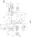
- FIG. 1 is a schematic diagram of components of an engine with an example programmable controller 10, which may include a processor 11 and a memory device 12.
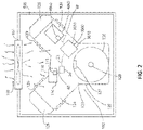
- FIG. 2 is a schematic view of an air-cooled internal combustion engine 100 including an example ignition module 3000.
- FIG. 3 is a schematic diagram of the ignition module 3000 of FIG. 1 which includes an integrated wireless transceiver 600.
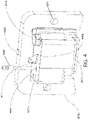
- FIG. 4 is a perspective view of a non-limiting structural arrangement of an ignition module housing 3010 integrating the ignition circuitry and wireless transceiver 600.
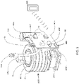
- FIG. 5 is a perspective view of internal components of an example ignition module 3000 integrating the ignition circuitry and wireless transceiver 600, removed from the housing 3010.
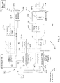
- FIG. 6 is a schematic diagram showing data communication and process flow paths between the ignition module and remote electronic devices in operable communication with each other.
- the engine 100 includes, or is connected with, an ignition module 3000.
- the controller 10 of the engine 100 is included in, or be connected with, an ignition module 3000.
- the ignition module 3000 includes an integrated wireless communication device such as wireless transceiver 600 mounted thereto.
- the ignition module 3000 may be partially or entirely encapsulated within a container or housing 3010, such as a metal can or a plastic housing, where the ignition module 3000 may be protected from the environment.
- the housing 3010 metal can or plastic housing, for example
- the housing 3010 may be sealed by the use of resins or epoxies in a vacuum potting operation to completely encapsulate the wires.
- Housing 3010 may be configured to attachment to chassis associated with engine or equipment to which the engine is mounted. In one implementation, the housing 3010 may be configured to for attachment to the engine crankcase 123 (see, e.g. FIG. 2 ), or other portion of the engine.
- the transceiver 600 may include circuitry configured to operate the transceiver 600 as a transmitter, a receiver, or both, for exchanging information or data. While the transceiver 600 is described herein as being capable of both receipt and transmission of data, in some embodiments, the transceiver 600 may only be a transmitting device, or a receiving device.
- Ignition module 3000 and/or processor 11 of controller 10 is configured to include circuitry, such as ignition circuitry 4000, temperature sensors TSE (engine temperature) and TSA (air temperature), etc. and/or devices (including non-transient computer readable storage medium such as volatile memory, non-volatile memory, etc.) for sensing, collecting, and/or storage of operational parameters, and/or data representing values of or associated with operational parameters, associated with the engine 100.
- the circuitry and/or devices may also or alternatively sense and/or collect operational parameters and/or data representing values of or associated with said operational parameters of engine 100's auxiliary equipment/systems described herein forming part of the engine operating system.
- the circuitry and/or devices may gather such operational parameters and/or data for calculation of derived values from the sensed data, for storage of the data and derived values, for engine system control, and/or for the wireless communication of data and derived values to a user's/operator's external electronic device 601 within transmission range.
- the circuitry and/or devices may include the sensors operable to detect and transmit measured values associated with temperature (e.g. TSE and TSA), pressure, electrical measurement parameters, exhaust gas characteristics, or others of interest.
- Electronic device 601 may be or include any electronic device external to the ignition module 3000 and ignition housing 3010 which is equipped to receive wireless signals from and/or transmit wireless signals to the wireless transceiver 600 using a wireless communication protocol (e.g. a "paired" device).
- Electronic device 601 may be remote, and/or portable.
- the term "remote” used herein with respect to "remote device” means a device which is not physically incorporated into the ignition module 3000 or located within the housing 3010 the ignition module 3000, and does not necessarily imply and include devices in proximity to the ignition module 3000 or those in a distal location.
- the electronic device 601 is not physically connected with the engine 100 or equipment which the engine 100 powers or is incorporated with.
- the electronic device may be connected with the engine 100 or equipment the engine 100 is incorporated into, such as a display on a riding lawn mower.
- Wireless transceiver 600 may form a wireless telemetry system which may exchange data/signals between the ignition module processor 11 and electronic device 601.
- the broadcast signals used to wirelessly transfer this data may utilize a variety of wireless communication protocols such as, but not limited to: LTE, Wi-Fi, Bluetooth, 60-GHz, Z-wave, Zigbee, radio, infrared, ultrasonic, GPS, and NFC (near-field communication) as some examples.
- GPS global positioning system
- GPS data may be used to identify weather conditions, which the system may respond to for adjusting an engine starting routine.
- NFC may be used for tagging, auto start/stop on proximity, and security lock). Infrared may be used for remote start features.
- the wireless transceiver 600 may communicate with a remote electronic device 601 via Bluetooth communication. Other variations are possible.
- the electronic device 601 may be configured via software or computer program instructions residing on the device 601 to identify when to make decisions or take action, identify which direction to make corrections, and identify or control priority of systems that may be controlled by the device 601.
- the computer program or software running on the portable electronic device 601 may also make control decisions and corrections in engine operation autonomously, and transmit control signals to the ignition module processor 11 via the wireless transceiver 600 to alter the engine's operation. Such control signals may be used for example to optimize engine performance, efficiency, and/or correct operating problems.
- the electronic device 601 may further be programmed to analyze the operating characteristics and parameters of the engine 100 received from the wireless communication device 600 for diagnostic purposes.
- hardwire data link connections like AUX, USB, CAN (or any serial communication), and/or LAN may be used for communicably linking the user's electronic device 601 to the processor 11 of the ignition module 3000.
- the ignition module processor 11 may be communicably linked to other external sensors or sources 602 of engine-related performance and operational data from devices not directly integrated physically with the ignition module 3000 (see, e.g. FIG. 3 ). This allows processor 11 to act as a central processing hub for collecting and processing all data derived from the engine 100, components of the engine 100, and/or the engine's auxiliary systems including those outside of the ignition module, and then wirelessly communicating that data to the external device 601 via transceiver 600. Examples of engine related performance data that may be monitored and collected include without limitation temperatures, pressures, fuel consumption, valve timing, voltages, amperages, air/fuel ratio, etc. associated with the air, fuel, or combustion systems.
- oil there may further be many aspects of oil which can be measured, such as pressure, temperature, viscosity, quality, contamination level, etc. Similar aspects may be measured for air and fuel. Other examples include engine speed in rpm, engine life in hours and choke position, engine load, power and torque to the list. Appropriate sensors or devices may thus be included to measure the foregoing or other engine operating parameters of interest. Other important parameters such as number of unsuccessful start attempts or engine misfires could be used as an indicator that a secondary problem (bad spark plug) might be occurring.
- Any suitable processor-based electronic device 601 may be used for communicating with the ignition module processor 11 via wireless transceiver 600, including for example without limitation a portable computer (e.g. laptop), tablet, cell phone, smart phone or watch, PDA, or other device. Alternatively in some embodiments, a desktop type computer may be the electronic device 601.
- the wireless transceiver 600 may include appropriate RFI shielding to prevent or minimize interference emanating from electromagnetic sources within the ignition module 3000 or engine 100.
- the transceiver 600 is oriented out of phase with the source of electromagnetic radiation. Integration of the wireless transceiver 600 directly with the ignition module 3000 in lieu of other remote mounting options may protect the integrity and quality of engine data secured, thereby benefitting the user by providing more reliable data which can be acted upon to extend the life of the engine and optimize its performance.
- the ignition module processor 11 may be configured via program instructions to collect and analyze engine operating/performance related data and perform basic analytics to generate derived engine data.
- the external electronic device 601 may configured via program instructions to perform more in-depth analytics on the data received from the processor 11 via wireless transceiver 600 necessary to make engine operational/performance decisions for altering the operation of the engine 100 or initiating maintenance/service procedures.
- Engine data collected by the ignition module processor 11 that has been transferred to the remote electronic device 601 or a local on-site operator or user can in turn be further transferred to a second remote distal electronic device 604 of the engine manufacturer located off site via various internet protocols.
- FIG. 6 is a schematic diagram showing the communication and data processing flow paths.
- the processor of the manufacturer's device can perform additional analytical steps on the data received as shown in FIG. 6 . Additional process steps may be performed.
- engine data and operator information that has been transferred to the manufacturer can help the manufacturer to predict service part volumes, thereby reducing the purchase of unnecessary parts, and/or warehouse space to store them.
- the engine data, in combination with the location of the operator, and/or the service use history of the engine can help the manufacturer of the engine observe trends in actual product use, and make decisions about engine configurations, engine parameters, and future product offerings.
- the engine 100 may comprise a carburetor 110 and an engine block 120.
- a fuel supply 130 may be operably coupled to the internal combustion engine 100 (such as to the carburetor 110).
- the ignition module 3000 may incorporate and include at least portions of an engine control mechanism such as without limitation an electronic auto-choke system 1000, which may be operably coupled to an internal combustion engine 100 (such as a spark-ignited gasoline engine) in accordance with a non-limiting embodiment of the present invention.
- an engine control mechanism such as without limitation an electronic auto-choke system 1000, which may be operably coupled to an internal combustion engine 100 (such as a spark-ignited gasoline engine) in accordance with a non-limiting embodiment of the present invention.
- this system 1000 may include various components, such as an adjustable choke valve 111 associated with carburetor 110, and various components which may control an operation and/or movement of the choke valve 111.
- this system and ignition module 3000 may include a wireless transceiver 600 and not include any electronic auto-choke system 1000.
- the ignition module 3000 may be operably coupled to a power supply 140, such as a battery, alternator or other energy storage device.
- a power supply 140 such as a battery, alternator or other energy storage device.
- the internal combustion engine 100 may include and be supplemented by many other sub-systems and elements/components.
- the controller 10, and/or the ignition module 3000 may include a processor 11 and a memory device 12. While the processor 11 and memory device 12 are exemplified as separate components, the memory device 12 may be integrated with the processor 11 in some embodiments. Moreover, while only one processor 11 and one memory device 12 are exemplified, the controller 10 may comprise multiple processors 11 and/or multiplier memory devices 12. Any suitable memory devices may be used including non-volatile memory and volatile memory.
- the processor 11 may be any computer central processing unit (CPU), microprocessor, micro-controller, computational device, or circuit configured for executing some or all of the processes described herein, including without limitation: (1) the retrieval and execution of the choke valve relational data tables: (2) the receipt, interpretation and usage of the temperature signals generated by the first and second temperature sensors 30, 40 as determining variables for the relational data tables; (3) the receipt, interpretation and usage of the engine speed signals generated by the engine speed sensor 60 in determining whether an engine cranking speed and/or engine starting speed has been reached, along with determining whether a low speed or high speed protocol should be used; (4) the generation and communication of the control signals that operate the actuator 20 to move the choke valve 111 to the desired position and at the desired rate; (5) the generation and communication of data via the wireless transceiver 600 to a remote electronic device 601; and/or (6) the receipt, interpretation, and usage or control based on data or control signals received from the remote electronic device 601 via the wireless transceiver 600.
- CPU central processing unit
- microprocessor
- the processor 11 may further obtain sensor data, process it, and send to the wireless transceiver 600.
- the processor 11 may be configured to receive a request from wireless transceiver module for ignition timing change, engine/application ID, security shutdown and performance change, and modify the choke and ignition timing characteristics based on those requests.
- the processor 11 can also be the power source to the wireless module.
- the processor may further control the timing of the data transmission/reception, and control what data to send and receive.
- the memory device 12 may include, without limitation, any suitable volatile or non-volatile memory including random access memory (RAM) and various types thereof, read-only memory (ROM) and various types thereof, USB flash memory, and magnetic or optical data storage devices (e.g. internal/external hard disks, floppy discs, magnetic tape CD-ROM, DVD-ROM, optical disk, ZIP TM drive, Blu-ray disk, and others), which may be written to and/or read by the processor 11 which is operably connected thereto.
- RAM random access memory
- ROM read-only memory
- USB flash memory e.g. internal/external hard disks, floppy discs, magnetic tape CD-ROM, DVD-ROM, optical disk, ZIP TM drive, Blu-ray disk, and others
- the memory device 12 may store the relational data tables (described in greater detail below) or other algorithms and/or calculations that can be used (by the processor 11) to transmit or receive data, determine the desired position of the choke valve 111 and/or the rate at which the choke valve 111 is moved, as well as control various other functions of the engine 100 or the engine's subsystems.
- the temperatures measured by each of the first and second temperature sensors 30, 40, along with the engine speed measured by the engine speed sensor 60, may be used as input variables for data collected by the processor 11, and/or to establish optimal positions of the choke valve 111 during a choke opening event and/or the rate at which the choke valve 111 moves between said optimal positions.
- the processor 11 of ignition module controller 10 may in turn send control signals to actuator 20 associated with the choke valve 111 to control the positon of the valve of flow of ambient combustion air to the combustion chamber 121.
- actuator 20 associated with the choke valve 111 to control the positon of the valve of flow of ambient combustion air to the combustion chamber 121.
- this enabled ignition module 3000 and the associated software could also control many other actuators, to control other aspects of engine operation.
- choke valve positioning and rate of movement calculations may take many forms, including without limitation, one or more algorithms, one or more relational data tables, or combinations thereof.
- the controller 10 may be operably coupled to the actuator 20.
- the actuator 20, in turn, may be operably coupled to the choke valve 111.
- the controller 10 may operate the actuator 20 in a desired manner by generating and transmitting control signals.
- the controller 10 may generate control signals based on the determinations made during carrying out of the method discussed herein (such as for example the four pulse sets).
- the actuator 20 may be appropriately activated, thereby adjusting/moving the choke valve 111 to a desired position that corresponds to that which has been determined by the controller 10.
- the actuator 20 may be appropriately activated, thereby adjusting position of the choke valve 111 and the rate at which the choke valve 111 moves.
- the choke valve 111 may be adjusted between a fully-closed position, a fully-open position, and any incremental and/or continuous positional setting between the fully-closed and fully-open position.
- One such position is a starting position that may be determined to be an optimal position for achieving start-up of the engine from an engine off state.
- the actuator 20 may be operably coupled to the choke valve 111 via a mechanical linkage 65. Mechanical linkages can take the form of any mechanical connection between the choke valve 111 and the actuator 20 such that when the actuator 20 operates/moves, there is a related and determined movement of the choke valve 111, which may be a choke plate of the carburetor 110.
- Mechanical linkages can comprise rods with ball and socket joints, linkage bars connected between the choke plate, and coupling of the end of the actuator shaft through a clevis.
- non-mechanical linkages are envisioned, such as electromagnetic and/or thermal couplings.
- a mechanical linkage 65 it is to be understood that the mechanical linkage 65 can take on a wide variety of linkage elements and arrangements thereof, none of which should be considered limiting of the present invention.
- the choke valve 111 in certain structural arrangements, may be a butterfly valve as is common in the art of carburetors.
- the position of a choke plate may be controlled by rotating or pivoting the choke plate via actuator 20 about a choke axis (which may be generally perpendicular to the direction of air flow) so that the choke plate assumes different angular positions within an air passageway of the carburetor 110.
- the choke plate may obstruct a different percentage of the transverse area of the air passageway of the carburetor 110. As a result, the flow characteristics of the ambient air flow 112 therethrough is altered.
- the fuel-to-air ratio of the fuel mixture that is created within the carburetor 110 is varied by the choke plate position.
- the choke valve 111 may be a butterfly valve comprising a pivotably adjustable choke plate, the choke valve 111 is not limited to a choke plate structure.
- the choke valve 111 can be any type of device that can be manipulated to various positions (i.e., settings) that ultimately varies the fuel-to-air ratio of the fuel mixture that is provided to the combustion chamber 121.
- the choke valve 111 can take the form of a gate valve, a globe valve, a pinch valve, a diaphragm valve, a needle valve, a plug valve, a ball valve, a control valve, or combinations thereof.
- the actuator 20 may comprise a stepper motor.
- the stepper motor may divide the rotation required to adjust the choke valve 111 from the fully-closed position to the fully-open position into a number of increments such that fine adjustment of the setting of the choke valve 111 may be achieved.
- the stepper motor's position can be commanded by the controller 10 to move and hold at any one of these increments.
- a relay control device or circuit 160 mounted directly inside ignition module housing 3000 on circuit board 4055 may be in the form of a motor driver circuit 160 (see, e.g. FIGS. 3 and 5 ) included as part of the electronic auto-choke system 1000.
- Motor driver circuit 160 may be operably coupled between the controller 10 and the actuator 20.
- the motor driver circuit 160 may be used to control and drive the current in one winding of the bipolar stepper motor and comprise a compatible logic input, a current sensor, a monostable and an output stage with built-in protection diodes. In certain other arrangements, the motor driver circuit may be omitted or built into the stepper motor itself. The motor driver circuit 160 may also comprise a separate internal timer that determines the driver rate. Additional controls for micro-stepping or half-stepping the actuator 20 may also be included if the design requires such a specialized control.
- the actuator 20 may be a stepper motor wherein motor movement is divided into equal increments of four motor steps. Four full steps of the unipolar stepper motor can also be seen as one full revolution of the motor. Motor movement in both directions may be referred to as revolutions. In one such example, a stepper motor is utilized in which 55 revolutions may be carried out to move the choke valve 111 from the fully-closed position to the fully-open position.
- the actuator 20 may be any device or assembly that can convert the control signal that is generated by the controller 10 into physical manipulation of the choke valve 111 to adjust the setting thereof.
- the actuator 20 may take the form of electric actuators, electromagnetic actuators, piezoelectric actuators, pneumatic actuators, hydraulic pistons, relays, comb drives, thermal bimorphs, digital micro-mirror devices and electroactive polymers.
- electric actuators may include a solenoid.
- actuator 20 (controlled by a relay control circuit such as motor drive circuit 160 mounted inside ignition module housing 3010) is described as controlling choke valve 111 which represents a pivotable type of engine control mechanism in the form a butterfly valve
- the invention is not limited to such engine control mechanisms of an auto choke system 1000.
- the relay control circuit may be configured to control other types of engine control mechanisms such as without limitation a sliding type control mechanism, a crank or gear mechanism, or other.
- the relay control circuit and actuator 20 are not limited to any particular type of engine control mechanism which can be controlled via controller 10 mounted in the ignition module 3000.
- the relay control circuit and actuator 60 may be used to control an electronic or pneumatically actuated engine control mechanism.
- the ignition module controller 10 may be used to control other devices and systems associated with the engine beyond that associated with an auto choke system. Accordingly, additional relay control circuits or drives mounted on circuit board 4055 and actuators may be provided which are controlled by controller 10 (see, e.g. FIG. 3 ).
- the first temperature sensor 30 may be positioned to measure a first temperature that is indicative of the temperature of the internal combustion engine 100.
- the first temperature sensor 30 may be mounted to the engine block 120 to measure the temperature of the engine block 120 itself as the first temperature.
- the term engine block may include the engine crankcase 123, the cylinder blocks 124, and the cylinder heads 125 (see FIG. 21).
- the first temperature sensor 30 may be mounted to another structure sufficiently adjacent to (or in thermal cooperation with) the engine block 120 such that a reliable temperature measurement thereof can be obtained.
- the first temperature sensor 30 may be mounted to or adjacent another component of the engine 100, and may measure the temperature at or adjacent that component.
- the first temperature sensor 30 may be mounted to the engine crankcase 123 itself at a position adjacent a flywheel 126 of the internal combustion engine 100 (see FIG. 21 ). In other arrangements, the first temperature sensor 30 may be mounted at alternate locations on the engine block 120 or may be mounted adjacent the engine block 120 and in contact therewith. In other arrangements, the first temperature sensor 30 may be in contact with a component in thermal cooperation with the engine block 120 that can provide a thermal reading that corresponds to the temperature of the engine block 120 in a determinable manner. In some embodiments, the first temperature sensor 30 may be mounted to the lamination stack 4070 of an ignition module 3000, which in turn is mounted to the engine crankcase 123 and, thus, is in thermal cooperation therewith.
- the first temperature sensor 30 may measure the engine temperature and output a first temperature signal that is indicative of the engine temperature. This first temperature signal may be transmitted to the controller 10 via the electrical connection/communication pathway 51 where it is utilized by the controller to determine starting position of the choke valve 111 and/or a rate at which the choke valve 111 is to be opened, as discussed in greater detail below).
- the first temperature sensor 30 can repetitively or continuously measure the first temperature so that the controller 10 is automatically provided with first temperature signals that are indicative of the engine temperature.
- the first temperature sensor 30 may periodically measure the engine temperature at predetermined temporal periods, predetermined engine events, and/or predetermined engine conditions so that the controller 10 is provided with first temperature signals that are indicative of the engine temperature only at certain desired times, engine events, engine conditions, or upon prompting.
- the first temperature sensor 30 may be an electrical temperature sensor.
- the first temperature sensor 30 may comprise one or more thermistors.
- the first temperature sensor 30 may comprise one or more thermocouples, resistance thermometers, silicon bandgap temperature sensors, thermostats, RTD's and/or state change temperature sensors.
- a second temperature sensor 40 may be positioned to measure a second temperature that may be indicative of the temperature of the ambient air 150.
- the ambient air 150 in which the second temperature sensor 40 may be positioned to measure the temperature of is eventually drawn into the carburetor 110 where it is used to create the fuel mixture that is delivered to the combustion chamber 121 via fuel mixture line 115.
- the second temperature sensor 40 may, however, be positioned at other locations that are exposed to the ambient air 150 that is not drawn into the carburetor.
- the second temperature sensor 40 may be positioned near a blower intake in an air-cooled engine arrangement (see FIG. 6 ) or at any position that is subjected to the ambient air 150.
- the second temperature sensor 40 may be positioned to measure other temperatures, such as a separate engine component temperature or air (such as intake, exhaust, or cooling air) temperature.
- the second temperature sensor 40 may measure the ambient air temperature and output a second temperature signal that may be indicative of the ambient air temperature. This second temperature signal may be transmitted to the controller 10 via the electrical connection/communication pathway 52 where it may be utilized by the controller 10 to determine a rate at which the choke valve 111 is to be opened. In other arrangements, the second temperature signal may also be utilized by the controller 10 to determine the starting position of the choke valve 111 (in combination with the first temperature signal).
- the second temperature sensor 40 can repetitively or continuously measure the second temperature so that the controller 10 is automatically provided with second temperature signals that are indicative of the ambient air temperature.
- the second temperature sensor 40 may periodically measure the second temperature at predetermined temporal periods, predetermined engine events, and/or predetermined engine conditions so that the controller 10 may be provided with second temperature signals that are indicative of the ambient air temperature only at certain desired times, engine events, engine conditions, or upon prompting.
- the second temperature sensor 40 may be an electrical temperature sensor.
- the second temperature sensor 40 may comprise one or more thermistors.
- the second temperature sensor 40 may comprise one or more thermocouples, resistance thermometers, and/or silicon bandgap temperature sensors.
- the second temperature sensor 40 may be omitted if ambient air temperature does not play a role in the determination of the optimization of choke valve positioning and/or rate of movement of the choke valve.
- the engine 100, ignition module 3000, and/or the electronic auto choke system 1000 may additionally comprise an engine speed sensor 60.
- the engine speed sensor 60 may be configured to measure the rotational speed of the internal combustion engine.
- the engine speed sensor 60 may be operably coupled to the controller 10 via the electrical pathway 55, as described above.
- the engine speed sensor 60 may measure the engine speed of the internal combustion engine and relays this information to the controller 10 so that the controller can utilize the measured engine speed in determining optimal positioning of the choke valve 111 and/or rate(s) at which the choke valve 111 is opened, as discussed in greater detail below. In one arrangement (see FIG.
- the engine speed sensor 60 may comprise a charging coil that may be considered a rotation sensor that, in response to a magnet on the flywheel, generates an electric charge due to a magnetic path being formed in a lamination stack.
- a rotation sensor may be provided that is a component other than and/or in addition to the charging coil that can detect rotation of the engine through mechanical, electrical or magnetic detection, potentially through proper coupling to a crankshaft or a camshaft.
- the engine speed sensor 60 can repetitively or continuously measure the engine speed so that the controller 10 may be automatically provided with engine speed measurements. Alternatively, the engine speed sensor 60 can periodically measure the engine speed at predetermined temporal periods, predetermined engine events, and/or predetermined engine conditions so that the controller 10 is provided with engine speed measurements only at certain desired times, engine events, engine conditions, or upon prompting.
- the engine 100, ignition module 3000, and/or auto-choke system 1000 may, in some embodiment, also include additional sensors so that other variables and/or data can be collected, sent to the electronic device 601, used for controlling the engine 100 or various subsystems of the engine 100, and/or taken into consideration in determining the optimal positioning of the choke valve 111 and/or the optimal rate at which the choke valve 111 is opened.
- sensors may be configured to measure air-to-fuel ratios (or oxygen levels) in the carburetor, engine load, and/or exhaust gas characteristic and take it into consideration in determining the optimal scheme for controlling the choke valve 111 opening. This may be accomplished by providing sensors or other mechanisms for measuring the desired parameter and/or condition and providing the measured parameter and/or condition to the controller 10.
- the determination of the position and rate of opening of the choke valve 111 may be modified in an appropriate manner to include the additional parameter and/or condition as a variable in determining the control scheme of the choke valve 111.
- an exhaust gas sensor 50 may be provided that measures an exhaust gas characteristic that is transmitted to the controller 10.
- the measurements from the sensor 50 may be used to determine combustion operation parameters for the engine 100, which may be stored and/or sent to the electronic device 601 for analysis and/or presentation to a user.
- the measurements from the sensor 50 may additionally or alternatively be collected for consideration in determining the optimized control scheme of the choke valve 111 during engine startup and/or shutdown.
- the exhaust gas sensor 50 may be operably coupled to an exhaust line 122 of the combustion chamber 121.
- the exhaust gas sensor 50 may measure a desired characteristic of the exhaust gas.
- the exhaust gas sensor 50 can, for example, be a concentration sensor that measures the concentration of a particular compound or gas in the exhaust gas stream, such as an oxygen concentration sensor.
- the exhaust gas sensor 50 may generate and transmit a signal indicative of the measured exhaust gas characteristic to the controller 10 for processing via the electrical connection/communication pathway 56.
- a modified version of the relational data tables (or other calculations or algorithms) may be stored in the memory device 12 that include the measured exhaust gas characteristic as a variable, in addition to the measured engine temperature, ambient air temperature, and/or engine speed.
- the processor 11 may retrieve the modified versions of the relational data tables from the memory device 12 and determine the optimal control scheme for the choke valve 111 using the modified versions of the relational data tables.
- the exhaust gas sensor 50 (or other sensor that is configured to measure a parameter indicative of the air-to-fuel ratio to be or being combusted in the combustion chamber) can be operably coupled to the controller 10 to form a closed feedback loop in which the rate and/or position of the choke valve 111 is dynamically controlled during the second choke opening stages COS2 in response to measurements taken by such a feedback sensor, which may be in substantially real-time.
- the ignition module 3000 may include the actuator 20, the controller 10 (which comprises the processor 11 and memory device 12), the first temperature sensor 30, the second temperature sensor 40, the motor driver circuit 160, and the electrical connection/communication pathways 51-54.
- the ignition module 3000 may further comprise an ignition circuit 4000 (regardless of whether the ignition module 3000 includes an auto-choke system 1000).
- the ignition circuit 4000 may comprise one or more of a charging coil 4010, a conditioning circuit 4020, an energy storage device 4030, a switch 4040, an ignition coil 4050, and a steel lamination stack 4070.
- the charging coil 4010, the conditioning circuit 4020, the energy storage device 4030, the switch 4040, and the ignition coil 4050 may be in operable cooperation with one another, and with the controller 10, via the electrical connection/communication pathways 56-60.
- the steel lamination stack 4070 may be operably positioned relative to the charging coil 4010.
- the charging coil 4010 can be conceptually considered an engine speed sensor that, in response to the magnet 127 of the flywheel 126, may generate an electric charge due to a magnetic path being formed in the steel lamination stack 4070.
- the charging coil 4010 may surround a central leg (not visible) of the steel lamination stack 4070 and, as the magnet 127 on the flywheel 126 severs the magnetic flux in the steel lamination stack 4070 as it passes, a magnetic path is formed within this central leg that, in turn, generates the electrical charge in the charging coil 4010.
- This induced electric charge not only may provide a pulse charge to the energy storage device 4030 (which may be a high voltage capacitor), but also may be received/detected by the controller 10 (after conditioning by the conditioning circuit 4020).
- the controller 10 may determine the rotational speed of the engine.
- the charging coil's electric pulses may be conditioned to provide a signal acceptable to the processor 11, as shown in the current diagram.
- a rotation sensor may be provided that is a component other than and/or in addition to the charging coil 4010 that can detect rotation of the engine through mechanical, electrical or magnetic detection, potentially through proper coupling to a crankshaft or a camshaft.
- the electrical connection/communication pathways 56-60 can comprise, without limitation, electrical wires, fiber-optics, communication cables, wireless communication paths, and combinations thereof.
- the exact structural nature and arrangement of the electrical connection/communication pathways 56-60 may not be limiting of the present invention, so long as each of the electrical connection/communication pathways 56-60 can facilitate the desired operation, communication, powering, and/or control between the coupled elements/components, as described in greater detail below.
- the ignition module 3000 may include a housing 3010 that may contain and/or encapsulate the ignition circuit 4000 and some or all of the elements/components of the electronic auto-choke control system 1000.
- the ignition module may be a magneto ignition system.
- the wireless transceiver 6000, the ignition circuit 4000, and in some cases control portions of the electronic auto choke system 1000 such as at least motor driver 160 within the same ignition module housing 3010 a single unit is created that can be mounted to the engine block 120 (specifically to the engine crankcase 123) in a single step.
- the ignition module 3000 can be mounted to the engine block 120 by coupling the steel lamination stack 4070 thereto via threaded bolts or other type fasteners.
- the steel lamination stack 4070 is, in turn, directly coupled to the housing 3010, thereby facilitating mounting of the entire integrated ignition module 3000 with stack 4070 to the engine block 210. As shown in FIG.
- the steel lamination stack 4070 may include mounting holes 4071 which receive fasteners to help provide secure mounting of the stack and ignition module 3000 to the engine block 210. It bears noting that the steel lamination stack 4070 may be incorporated and mounted directly to the ignition module housing 3010, and either completely exposed or partially encapsulated within the potting compound 4080 of the housing 3010. If partially encapsulated, at least portions of the steel lamination stack 4070 with mounting holes 4071 may remain exposed for mounting to the engine block. The steel lamination stack 4070 may physically adjoin the charging coil 4010 which is encapsulated within the potting compound 4080 of the ignition module housing 3010.
- the controller 10 can be configured to control the ignition circuit 4000, such as by controlling the timing for firing the spark plugs 4060.
- the controller 10 may adjust the firing angle (retard firing) and optimize ignition timing when choking the engine.
- the housing 3010 can define a single internal cavity or can include internal walls that divide the internal cavity into multiple chambers. Additionally, the housing 3010 may be a fully enclosed housing or a partially enclosed housing having at least one open side. In the exemplified arrangement, the housing 3010 includes a potting compound 4080 that seals the interior thereof, along with the components enclosed therein for protecting against the engine operating environment.
- the controller 10 and the motor driver circuit 160 may be fully disposed within an interior cavity of the housing 3010.
- the first temperature sensor 30, if included, may partially protrude outwards from inside the housing 3010. More specifically, the first temperature sensor 30 may protrude from the housing 3010 and may be coupled to the steel lamination stack 4070 so as to be in thermal coupling therewith. In some embodiments, the first temperature sensor 30 may be embedded in the steel lamination stack 4070. As a result of being coupled to (which includes embedding) the steel lamination stack 4070, the first temperature 30 measures the temperature of the steel lamination stack 4070, which in turn becomes heated (and cooled) in a manner corresponding to the engine block 120 due its thermal cooperation therewith. Thus, the first temperature sensor 30 measures the engine block temperature.
- the second temperature sensor 40 may also partially protrude outwards from inside the housing 3010 so that at least a portion of the second temperature sensor 40 remains exposed to the surrounding environment. This may allow the ambient air 150 that enters the blower housing 500 to come into contact with the second temperature sensor 40. As a result, despite being part of the ignition module 3000, the second temperature sensor 40 may still measure the temperature of the ambient air flow 150. In certain arrangements of the ignition module 3000, the second temperature sensor 40 may be located entirely outside of the housing 3010 and may even be omitted.
- FIG. 3 shows the arrangement of components with respect to which components may be physically mounted to and/or inside the ignition module housing 3010, and those components which may be located externally to the housing either proximately or more remotely.
- the ignition module housing 3010 is represented by a solid line as shown.
- the components located inside the solid line are directly mounted to and inside the housing 3010 being fully encapsulated by the potting compound 4080 for protection from the engine operating environment (e.g. transceiver 600, ignition coil 4050, charging coil 4010, controller 10, motor driver 160, etc.).
- Components such as temperature sensors 30 and 40 are partially encapsulated within the potting compound 4080 and housing 3010 such that a portion of the sensors remains exposed to measure temperatures external to the ignition module housing.
- FIG. 4 shows one embodiment of an ignition module housing 3010 of the ignition module 3000.
- the ignition module 3000 may be mounted to the engine block 120 adjacent the flywheel 126.
- the ignition module 3000 may be mounted to the engine crankcase 123 adjacent the flywheel 126, for example, by the steel lamination stack 4070 as described above.
- a magnet 127 may be provided on the flywheel 126. During rotation of the flywheel 126 about the crankshaft 128, the magnet 127 may pass the ignition module steel lamination 4070 cutting the magnetic flux lines and creating a magnetic field in the central leg that causes charging coil 4010 to generate a high voltage supply that charges the energy storage device 4030, which may be a high voltage capacitor.
- the switch 4040 which is in the form of a semiconductor-controlled rectifier, may transfer the energy stored in the energy storage device 4030 to the primary 4051 of the ignition coil 4050, thereby creating a magnetic field that charges the secondary 4052 of the ignition coil 4050. As a result of the secondary 4052 being charged, the spark plug 4060 may be fired/sparked.
- the controller 10 through its monitoring of the rotational speed and rotation positioning of the engine (via for example the position of the engine crankshaft and/or camshaft), may synchronize the spark of the spark plug 4060 with the engine rotation.
- the conditioning circuit 4020 may perform one or more of the following functions: (1) optimization of the gate current of the switch 4040 for all the RPM range; (2) filters parasitic strikes occurring on the sensor signal; and/or (3) ensures the correct lead angle.
- the ignition circuit 4000 may be exemplified as a capacitive discharge ignition, it is to be understood that various types of ignition circuits can be incorporated into the ignition module 3000 in accordance with the present invention, such as an inductive discharge ignition. Additionally, while a magneto ignition system is exemplified, the ignition module 3000 may comprise other types of ignition systems, such as a battery and coil-operated ignition, a mechanically timed ignition, and an electronic ignition.
- the ignition module controller 10 may comprise two processors 11, which are mounted to a circuit board 4055, along with the motor driver 160, the switch 4040, the energy storage device 4030 and a shut-off terminal 4096. Additionally, a ground tab 4090 is also provided. The ground tab 4090 is coupled to the steel lamination stack 4070, which acts as the ground through its coupling to the engine block 120. A power in line 4098 is also provided for receiving 12V power. Leads 4097 protrude from the potting compound 4080 of the housing 3010 for connection to the motor/DLA. Similarly, a high voltage secondary lead 4095 also protrudes from the housing 3010 for electrically coupling to the spark plug boot and terminal.
- the internal combustion engine 100 may be an air-cooled engine and thus comprises a plurality of heat conducting fins 129 extending from the cylinder banks 124. Moreover, the internal combustion engine 100 is positioned within a blower housing 500 that comprises a blower 501 that draws in and forces an ambient air flow 150 over the internal combustion engine 100, including over the second temperature sensor 40 and into the carburetor 110.
- the ignition module 3000 may gather data from any of the above-referenced sensors, may analyze any of said collected data, and/or may send such data to the remote electronic device 601, which may itself analyze said data.
- the ignition module 3000, or the electronic device 601 may use collected and/or analyzed data to identify preventative maintenance or failures associated with the engine 100. For example, data related to the run time of the engine 100 may be collected and analyzed to determine when the engine oil should be replaced.
- the data, or an engine oil change signal may be transmitted by the ignition module 3000 to the electronic device 601, and displayed to the end user.
Landscapes
- Engineering & Computer Science (AREA)
- Chemical & Material Sciences (AREA)
- Combustion & Propulsion (AREA)
- Mechanical Engineering (AREA)
- General Engineering & Computer Science (AREA)
- Signal Processing (AREA)
- Combined Controls Of Internal Combustion Engines (AREA)
- Ignition Installations For Internal Combustion Engines (AREA)
Applications Claiming Priority (2)
| Application Number | Priority Date | Filing Date | Title |
|---|---|---|---|
| US201662432926P | 2016-12-12 | 2016-12-12 | |
| US15/829,540 US10634111B2 (en) | 2016-12-12 | 2017-12-01 | Ignition module for internal combustion engine with integrated communication device |
Publications (3)
| Publication Number | Publication Date |
|---|---|
| EP3333413A2 EP3333413A2 (en) | 2018-06-13 |
| EP3333413A3 EP3333413A3 (en) | 2018-09-05 |
| EP3333413B1 true EP3333413B1 (en) | 2022-06-29 |
Family
ID=60654703
Family Applications (1)
| Application Number | Title | Priority Date | Filing Date |
|---|---|---|---|
| EP17205680.6A Active EP3333413B1 (en) | 2016-12-12 | 2017-12-06 | Ignition module for internal combustion engine with integrated communication device |
Country Status (3)
| Country | Link |
|---|---|
| US (1) | US10634111B2 (zh) |
| EP (1) | EP3333413B1 (zh) |
| CN (1) | CN108223235A (zh) |
Families Citing this family (5)
| Publication number | Priority date | Publication date | Assignee | Title |
|---|---|---|---|---|
| WO2018075732A1 (en) * | 2016-10-19 | 2018-04-26 | Walbro Llc | Control and communication module for light-duty combustion engine |
| US12105579B2 (en) * | 2017-04-13 | 2024-10-01 | Texas Tech University System | System and method for automated prediction and detection of component and system failures |
| US10819194B2 (en) * | 2018-08-27 | 2020-10-27 | Honda Motor Co., Ltd. | Internal combustion engine with integrated connectivity device |
| US10785908B2 (en) | 2018-08-27 | 2020-09-29 | Honda Motor Co., Ltd. | Internal combustion engine with integrated connectivity device |
| US10756603B2 (en) | 2018-08-27 | 2020-08-25 | Honda Motor Co., Ltd. | Internal combustion engine with wireless communications device |
Family Cites Families (160)
| Publication number | Priority date | Publication date | Assignee | Title |
|---|---|---|---|---|
| US1812517A (en) | 1929-07-04 | 1931-06-30 | Bosch Robert | Battery ignition apparatus |
| ATE121208T1 (de) | 1990-01-30 | 1995-04-15 | Johnson Service Co | Vernetztes betriebsmittelverwaltungssystem. |
| US5568121A (en) | 1993-05-27 | 1996-10-22 | Lamensdorf; David M. | Wireless system for sensing information at remote locations and communicating with a main monitoring center |
| DE4425388B4 (de) | 1994-07-19 | 2005-07-21 | Robert Bosch Gmbh | Steuergerät |
| US6744352B2 (en) | 1995-11-09 | 2004-06-01 | Vehicle Enhancement Systems, Inc. | System, apparatus and methods for data communication between vehicle and remote data communication terminal, between portions of vehicle and other portions of vehicle, between two or more vehicles, and between vehicle and communications network |
| US5949247A (en) | 1996-05-23 | 1999-09-07 | Fremont/Dynamics Coporation Of America | Method and apparatus for automatically testing and evaluating electric generator sets |
| US5803043A (en) | 1996-05-29 | 1998-09-08 | Bayron; Harry | Data input interface for power and speed controller |
| JP3350632B2 (ja) | 1996-09-18 | 2002-11-25 | 株式会社ミツバ | 車両用盗難防止装置 |
| US7216043B2 (en) | 1997-02-12 | 2007-05-08 | Power Measurement Ltd. | Push communications architecture for intelligent electronic devices |
| IT1303625B1 (it) | 1998-07-24 | 2000-11-15 | Gruppi Pinasco S R L | Limitatore variabile di velocita' per veicoli a motore conaccensione elettronica. |
| CN2381807Y (zh) | 1998-12-15 | 2000-06-07 | 王殿玖 | 车用遥控防盗点火器 |
| US6338013B1 (en) | 1999-03-19 | 2002-01-08 | Bryan John Ruffner | Multifunctional mobile appliance |
| EP1246414B1 (en) | 1999-05-26 | 2012-05-23 | Johnson Controls Technology Company | Wireless communications system and method therefor |
| US6882917B2 (en) | 1999-07-30 | 2005-04-19 | Oshkosh Truck Corporation | Steering control system and method |
| US6163088A (en) | 1999-09-30 | 2000-12-19 | Caterpillar Inc. | Method and apparatus for providing standby power from a generator using capacitor supplied voltage |
| US6392312B1 (en) | 1999-10-26 | 2002-05-21 | Gary Jay Morris | Portable electric power generator with remote control and safety apparatus |
| US6668629B1 (en) | 1999-11-26 | 2003-12-30 | General Electric Company | Methods and apparatus for web-enabled engine-generator systems |
| US7990985B2 (en) | 2000-01-31 | 2011-08-02 | 3E Technologies International, Inc. | Broadband communications access device |
| US6560528B1 (en) * | 2000-03-24 | 2003-05-06 | Internal Combustion Technologies, Inc. | Programmable internal combustion engine controller |
| US6707169B2 (en) | 2000-07-19 | 2004-03-16 | Honda Giken Kogyo Kabushiki Kaisha | Engine generator, controller, starter apparatus, and remote control system for the engine generator |
| JP4329972B2 (ja) | 2000-08-09 | 2009-09-09 | 本田技研工業株式会社 | エンジン発電機の遠隔操作システム |
| US7904219B1 (en) | 2000-07-25 | 2011-03-08 | Htiip, Llc | Peripheral access devices and sensors for use with vehicle telematics devices and systems |
| US6522955B1 (en) | 2000-07-28 | 2003-02-18 | Metallic Power, Inc. | System and method for power management |
| US6631310B1 (en) | 2000-09-15 | 2003-10-07 | General Electric Company | Wireless engine-generator systems digital assistant |
| US6653821B2 (en) | 2001-06-15 | 2003-11-25 | Generac Power Systems, Inc. | System controller and method for monitoring and controlling a plurality of generator sets |
| US6657416B2 (en) | 2001-06-15 | 2003-12-02 | Generac Power Systems, Inc. | Control system for stand-by electrical generator |
| CA2398408A1 (en) | 2001-08-17 | 2003-02-17 | Dynagen Technologies Incorporated | Power transfer switch assembly |
| US7191053B2 (en) | 2001-12-21 | 2007-03-13 | Astroflex Inc. | Remote starting system for a vehicle |
| US20030224833A1 (en) | 2002-05-29 | 2003-12-04 | Thomas Egan | Cellular base station power generator having remote monitoring and control |
| US20080265844A1 (en) * | 2002-06-06 | 2008-10-30 | Black & Decker Inc. | Starter system for portable internal combustion engine electric generators using a portable universal battery pack |
| US20030236723A1 (en) | 2002-06-25 | 2003-12-25 | Angott Paul G. | Automatic billing system for a lawn mowing service using GPS |
| WO2004004236A2 (en) | 2002-06-27 | 2004-01-08 | Snap-On Incorporated | Portal for distributing business and product information |
| US7173348B2 (en) * | 2003-03-03 | 2007-02-06 | Startech Automotive Anti Theft Systems Ltd. | Device, system and method for preventing vehicle theft |
| WO2004094813A1 (en) | 2003-04-17 | 2004-11-04 | Snap-On Incorporated | Sampling of combined (tangled) electric near fields in hybrid and distributorless ignition system |
| US7353897B2 (en) | 2003-07-23 | 2008-04-08 | Fernandez Dennis S | Telematic method and apparatus with integrated power source |
| JP3902168B2 (ja) | 2003-09-04 | 2007-04-04 | 日立建機株式会社 | 建設機械の診断情報表示システム |
| US7076348B2 (en) | 2003-09-09 | 2006-07-11 | Ariens Company | Data collection apparatus and method |
| US7356305B2 (en) | 2003-12-19 | 2008-04-08 | Palo Alto Research Center Incorporated | Vehicle enabled networks |
| US20060154642A1 (en) | 2004-02-20 | 2006-07-13 | Scannell Robert F Jr | Medication & health, environmental, and security monitoring, alert, intervention, information and network system with associated and supporting apparatuses |
| US10417298B2 (en) | 2004-12-02 | 2019-09-17 | Insignio Technologies, Inc. | Personalized content processing and delivery system and media |
| US7213555B2 (en) | 2004-03-12 | 2007-05-08 | Honda Motor Co., Ltd. | Automatic choke |
| US20050267713A1 (en) | 2004-05-27 | 2005-12-01 | Caterpillar Inc. | Data acquisition system for generating operator-indexed information |
| US20060101927A1 (en) | 2004-11-18 | 2006-05-18 | Blakeley Gerald W Iii | Analytical measurement meters with location determination capability |
| WO2006096854A2 (en) | 2005-03-08 | 2006-09-14 | E-Radio Usa, Inc. | Systems and methods for modifying power usage |
| US8704678B2 (en) | 2005-03-08 | 2014-04-22 | Jackson Kit Wang | Systems and methods for modifying utility usage |
| US7333922B2 (en) | 2005-03-30 | 2008-02-19 | Caterpillar Inc. | System and method of monitoring machine performance |
| US8224499B1 (en) | 2005-05-03 | 2012-07-17 | Omnimetrix, Llc | Remote annunciator |
| US20060277884A1 (en) | 2005-06-10 | 2006-12-14 | Ariens Company | Object detection system for a lawn mower |
| US20070089157A1 (en) | 2005-10-18 | 2007-04-19 | Clark Christopher M | Television advertising number system |
| US20070143000A1 (en) | 2005-12-16 | 2007-06-21 | Trevor Scott Bryant | Wireless Spark Energy Indicator |
| US7544943B2 (en) | 2006-01-18 | 2009-06-09 | Mutual Sky Technology Limited | Method and system for remote exhaust emission measurement |
| US7660652B2 (en) | 2006-02-02 | 2010-02-09 | Signature Control Systems, Inc. | Method, system and device for monitoring vehicle usage |
| US20110267080A1 (en) | 2006-02-17 | 2011-11-03 | Hedges Joe D | Remote Oil Monitoring System |
| US9201842B2 (en) | 2006-03-16 | 2015-12-01 | Smartdrive Systems, Inc. | Vehicle event recorder systems and networks having integrated cellular wireless communications systems |
| EP3404505B1 (en) | 2006-03-17 | 2023-12-06 | iRobot Corporation | Lawn care robot |
| US7584026B2 (en) | 2006-04-19 | 2009-09-01 | Edward D. Siemer, Jr. | Wirelessly controlled motorized vehicle system |
| US7787997B2 (en) | 2006-04-28 | 2010-08-31 | Caterpillar | Modular electric power generation system and method of use |
| US20070277403A1 (en) | 2006-06-05 | 2007-12-06 | Stephen David Summer | Automated snow removal tracking system |
| US7747739B2 (en) | 2006-08-10 | 2010-06-29 | Gridpoint, Inc. | Connection locator in a power aggregation system for distributed electric resources |
| US20080073090A1 (en) | 2006-09-26 | 2008-03-27 | Gary Harris | Automated snow plow |
| US20080086391A1 (en) | 2006-10-05 | 2008-04-10 | Kurt Maynard | Impromptu asset tracking |
| US8989959B2 (en) | 2006-11-07 | 2015-03-24 | Smartdrive Systems, Inc. | Vehicle operator performance history recording, scoring and reporting systems |
| US8868288B2 (en) | 2006-11-09 | 2014-10-21 | Smartdrive Systems, Inc. | Vehicle exception event management systems |
| US8306659B2 (en) | 2006-12-06 | 2012-11-06 | F Robotics Acquisitions Ltd. | Autonomous robot |
| US20080147267A1 (en) | 2006-12-13 | 2008-06-19 | Smartdrive Systems Inc. | Methods of Discretizing data captured at event data recorders |
| US8139820B2 (en) | 2006-12-13 | 2012-03-20 | Smartdrive Systems Inc. | Discretization facilities for vehicle event data recorders |
| US20080179139A1 (en) | 2007-01-30 | 2008-07-31 | Deere & Company | Oil change apparatus |
| US20080234919A1 (en) | 2007-03-16 | 2008-09-25 | Curtis Paul Ritter | Performing application review validation testing for an engine as installed in an application |
| US8345047B2 (en) | 2007-05-30 | 2013-01-01 | Deere & Company | Method for displaying performance information for one or more vehicles |
| US8027761B1 (en) | 2007-09-04 | 2011-09-27 | Nelson Russell G | Local positioning system for automated lawn mowers |
| WO2009039155A2 (en) | 2007-09-19 | 2009-03-26 | Briggs And Stratton Corporation | Power monitoring system |
| WO2009058972A2 (en) | 2007-10-30 | 2009-05-07 | Sosy Technologies Stu, Inc. | An apparatus for collecting, storing and transmitting vehicle information |
| US20090191034A1 (en) | 2007-12-27 | 2009-07-30 | Ty-Crop Manufacturing Ltd. | Remote controllable material handling system |
| WO2010019179A1 (en) | 2008-04-19 | 2010-02-18 | Jitendra Batra | Power storage and power transfer method and apparatus |
| US8219305B2 (en) | 2008-05-27 | 2012-07-10 | Briggs & Stratton Corporation | Engine with an automatic choke and method of operating an automatic choke for an engine |
| WO2010000262A1 (en) | 2008-06-09 | 2010-01-07 | Nijunge | A device for making diagnostic tests on a vehicle |
| DE102008053605A1 (de) | 2008-10-17 | 2010-04-29 | Ammersee Solar Gmbh | Generatorwagen |
| EP2369908A4 (en) | 2008-12-30 | 2012-09-26 | Husqvarna Ab | SELF-CONTAINING ROBOTIC TURF MOWER AND METHOD FOR ESTABLISHING A WIRELESS COMMUNICATION CONNECTION BETWEEN LAWN MOWER AND A USER |
| US20100182157A1 (en) | 2009-01-22 | 2010-07-22 | Delphi Technologies, Inc. | Wireless battery sensor |
| US9020769B2 (en) | 2009-01-26 | 2015-04-28 | Geneva Cleantech Inc. | Automatic detection of appliances |
| CA2694597C (en) | 2009-02-25 | 2017-02-21 | Robert Joseph Berry, Jr. | Universal remote machinery controller and monitor |
| RO126154A2 (ro) | 2009-07-09 | 2011-03-30 | Mohamed Amir | Sistem şi metodă pentru supravegherea şi monitorizarea consumului de combustibil lichid la autovehicule de transport rutier |
| US20110007491A1 (en) | 2009-07-10 | 2011-01-13 | Protonex Technology Corporation | Portable power manager enclosure |
| US8213962B2 (en) | 2009-07-21 | 2012-07-03 | Verizon Patent And Licensing Inc. | Vehicle computer link to mobile phone |
| US8315718B2 (en) | 2009-10-02 | 2012-11-20 | General Electric Company | Control systems and methods of providing the same |
| US8619141B2 (en) | 2009-12-22 | 2013-12-31 | Deere & Company | Portal management |
| US10358791B2 (en) | 2010-01-26 | 2019-07-23 | Husqvarna Ab | Laying machine |
| US8903597B2 (en) | 2010-04-30 | 2014-12-02 | Cability, Inc. | Multipurpose in-vehicle diagnostic II adapter |
| US9311616B2 (en) | 2010-06-14 | 2016-04-12 | On-Board Communications, Inc. | System and method for determining equipment utilization changes based on ignition and motion status |
| US9043078B2 (en) | 2010-08-13 | 2015-05-26 | Deere & Company | Method and system for performing diagnostics or software maintenance for a vehicle |
| US8463953B2 (en) | 2010-08-18 | 2013-06-11 | Snap-On Incorporated | System and method for integrating devices for servicing a device-under-service |
| US8560168B2 (en) | 2010-08-18 | 2013-10-15 | Snap-On Incorporated | System and method for extending communication range and reducing power consumption of vehicle diagnostic equipment |
| US9246332B2 (en) | 2010-10-01 | 2016-01-26 | General Electric Company | Household energy management system and method for one or more appliances and power generator |
| US20120101679A1 (en) | 2010-10-26 | 2012-04-26 | Noel Wayne Anderson | Method and system for enhancing operating performance of an autonomic mobile robotic device |
| DE102010043893A1 (de) | 2010-11-15 | 2012-05-16 | Robert Bosch Gmbh | Zündsystem und Betriebsverfahren hierfür |
| DE102010043894A1 (de) | 2010-11-15 | 2012-05-16 | Robert Bosch Gmbh | Abdeckvorrichtung für einen Zündkerzenschacht, Steuereinrichtung für eine Zündkerze und Verfahren zum Betreiben einer Zündkerze |
| KR20120075555A (ko) | 2010-11-23 | 2012-07-09 | 김수진 | 스마트폰을 이용한 운전 정보 관리 시스템 및 방법 |
| US8833861B2 (en) | 2010-12-03 | 2014-09-16 | Caterpillar Inc. | Loading analysis system and method |
| GB2492954A (en) | 2010-12-06 | 2013-01-23 | Agco Corp | A system for automatic agricultural reporting |
| US8344529B2 (en) | 2011-01-18 | 2013-01-01 | Energy Intelligence, LLC | Method and system for energy harvesting |
| EP3954505B1 (en) | 2011-07-24 | 2024-10-02 | Makita Corporation | Adapter for power tools |
| KR101334961B1 (ko) | 2011-08-03 | 2013-11-29 | 엘지전자 주식회사 | 잔디 깎기용 이동로봇 시스템 및 이의 제어방법 |
| US9471063B2 (en) | 2011-08-11 | 2016-10-18 | Chien Ouyang | Robotic lawn mower with network sensors |
| US8947202B2 (en) | 2011-10-20 | 2015-02-03 | Apple Inc. | Accessing a vehicle using portable devices |
| US9041556B2 (en) | 2011-10-20 | 2015-05-26 | Apple Inc. | Method for locating a vehicle |
| US9491903B2 (en) | 2011-10-28 | 2016-11-15 | Husqvarna Ab | Steering assembly indicator system for a lawn care or zero-turn vehicle |
| WO2013062569A1 (en) | 2011-10-28 | 2013-05-02 | Husqvarna Consumer Outdoor Products N.A., Inc. | Indicator system for outdoor power equipment |
| WO2013062572A1 (en) | 2011-10-28 | 2013-05-02 | Husqvarna Consumer Outdoor Products N.A., Inc. | Hood-mounted indicator system for riding lawn care vehicle |
| CN104010879B (zh) | 2011-10-28 | 2016-09-07 | 胡斯华纳有限公司 | 启动故障指示器系统 |
| US8733072B2 (en) | 2011-11-04 | 2014-05-27 | Briggs & Stratton Corporation | Starter system for an engine |
| US8857138B2 (en) | 2011-11-04 | 2014-10-14 | Briggs & Stratton Corporation | Starter system for an engine |
| US10328514B2 (en) | 2011-11-07 | 2019-06-25 | Lincoln Global, Inc. | Use of mobile communications devices as user interface for welding equipment and systems |
| US8509812B2 (en) | 2011-12-27 | 2013-08-13 | Flextronics Ap, Llc | Method and system for collecting automobile-related travel data with a smartphone |
| AU2012362308B2 (en) | 2011-12-28 | 2016-05-19 | Husqvarna Ab | Electrical system for riding lawn care vehicle |
| WO2013100941A2 (en) | 2011-12-28 | 2013-07-04 | Husqvarna Consumer Outdoor Products N.A., Inc. | Yard maintenance vehicle obstacle avoidance/notification system |
| EP2798420B1 (en) | 2011-12-28 | 2017-04-19 | Husqvarna AB | Yard maintenance vehicle route and orientation mapping system |
| US20150006025A1 (en) | 2011-12-28 | 2015-01-01 | Husqvarna Ab | Lawn care vehicle with modular ride information system |
| US20130201316A1 (en) | 2012-01-09 | 2013-08-08 | May Patents Ltd. | System and method for server based control |
| US20130214602A1 (en) | 2012-02-20 | 2013-08-22 | Engineered Electric Company | Method and system for generator control |
| EP2823468A4 (en) | 2012-03-08 | 2015-12-23 | Husqvarna Ab | SYSTEM AND METHOD FOR ENGINE SPEED DATA UTILIZATION |
| WO2013134620A1 (en) | 2012-03-08 | 2013-09-12 | Husqvarna Ab | Automated operator-equipment pairing system and method |
| CN104428165A (zh) | 2012-05-09 | 2015-03-18 | 冷王公司 | 运输制冷系统的远程监控 |
| US9957920B2 (en) | 2012-06-19 | 2018-05-01 | Econtrols, Llc | Highly accurate continuous-flow vaporized fuel supply for large dynamic power ranges |
| EP2866980A4 (en) | 2012-06-26 | 2016-07-20 | Husqvarna Ab | REMOVABLE USER INTERFACE FOR A ROBOT VEHICLE |
| AU2012385408A1 (en) | 2012-07-09 | 2015-02-05 | Techtronic Outdoor Products Technology Limited | An interface for a power tool |
| US9563215B2 (en) | 2012-07-14 | 2017-02-07 | Causam Energy, Inc. | Method and apparatus for actively managing electric power supply for an electric power grid |
| US9497901B2 (en) | 2012-08-14 | 2016-11-22 | Husqvarna Ab | Boundary definition system for a robotic vehicle |
| WO2014027945A1 (en) | 2012-08-14 | 2014-02-20 | Husqvarna Ab | Mower with object detection system |
| US8736438B1 (en) | 2012-08-15 | 2014-05-27 | Google Inc. | Computing device as a vehicle key |
| US9194091B2 (en) | 2012-08-16 | 2015-11-24 | The Toro Company | Wireless snow plow control |
| US9249773B2 (en) | 2012-10-23 | 2016-02-02 | GM Global Technology Operations LLC | Apparatus and method for static testing a spark plug assembled in an internal combustion engine including cracked ceramic insulator detection |
| KR101410981B1 (ko) | 2012-11-26 | 2014-06-23 | 조선대학교산학협력단 | 자율 작업형 잔디깎기 장치 |
| DE202012104841U1 (de) | 2012-12-12 | 2014-03-13 | Heinz Tillack | Anordnung zur Überwachung und Beeinflussung von Kfz-Antriebssträngen mittels mobiler Kommunikationsgeräte, wie Smartphones |
| DE102013202075A1 (de) | 2013-02-08 | 2014-08-14 | Robert Bosch Gmbh | Bewegungsstrategieerarbeitungs- und/oder Navigationsvorrichtung |
| US9330561B2 (en) | 2013-03-04 | 2016-05-03 | Hello Inc. | Remote communication systems and methods for communicating with a building gateway control to control building systems and elements |
| EP2964009B1 (en) | 2013-03-05 | 2017-04-26 | Husqvarna AB | Energy harvesting wireless sensor network |
| EP2966968B1 (en) | 2013-03-13 | 2021-01-06 | Husqvarna AB | Riding lawn care vehicle auto idle system |
| US20140265555A1 (en) | 2013-03-15 | 2014-09-18 | Witricity Corporation | Series relayed wireless power transfer in a vehicle |
| US20140284022A1 (en) | 2013-03-25 | 2014-09-25 | Blockhead International LLC | Portable heating unit |
| CN104144249A (zh) | 2013-05-09 | 2014-11-12 | 张玉辉 | 一种多功能手机 |
| KR101326253B1 (ko) | 2013-05-21 | 2013-11-11 | 주식회사 초록세상 | 태양광 발전기용 접속반 및 그 제어방법 |
| CN203398942U (zh) | 2013-06-17 | 2014-01-15 | 杭州诚德发电设备有限公司 | 可视化蓝牙转子测温发电机 |
| CN203325191U (zh) | 2013-07-04 | 2013-12-04 | 中能电力科技开发有限公司 | 基于蓝牙传输的风电机组叶片载荷采集系统 |
| US20150021113A1 (en) | 2013-07-17 | 2015-01-22 | Robert Lefevbre | Cellular phone ignition interlock device and method of controlling cellular phone usage |
| US9464588B2 (en) | 2013-08-15 | 2016-10-11 | Kohler Co. | Systems and methods for electronically controlling fuel-to-air ratio for an internal combustion engine |
| US10130962B2 (en) | 2013-10-10 | 2018-11-20 | Briggs & Stratton Corporation | Wirelessly controlled trigger start and chemical tank change-over for pressure washers |
| US9794652B2 (en) | 2013-10-31 | 2017-10-17 | Delta Systems, Inc. | Smart monitoring system and method of operation |
| EP2870853A1 (en) | 2013-11-11 | 2015-05-13 | Honda Research Institute Europe GmbH | Lawn mower with remote control |
| US9303571B2 (en) | 2013-11-13 | 2016-04-05 | Fca Us Llc | Torque management techniques for engine systems having belt-driven starter generators |
| US10060827B2 (en) | 2014-01-17 | 2018-08-28 | Kohler Co. | Fleet management system |
| US9624891B2 (en) | 2014-02-21 | 2017-04-18 | Briggs & Stratton Corporation | Outdoor power equipment incorporating starter battery with integrated push button |
| KR101463371B1 (ko) | 2014-03-24 | 2014-11-18 | 호서대학교 산학협력단 | 엔진오일 상태 감시 장치, 엔진오일 상태 표시 장치, 엔진오일 상태 표시 프로그램이 기록되어 있는 컴퓨터 판독 가능한 기록매체 |
| US9939868B2 (en) | 2014-05-12 | 2018-04-10 | Gary Stephen Shuster | Device power and resource management |
| US20140277967A1 (en) | 2014-05-27 | 2014-09-18 | Caterpillar Inc. | Distributed worksite management system |
| EP3245856B1 (de) | 2014-06-18 | 2019-11-20 | Deere & Company | Anordnung zur kontrolle einer geräteschnittstelle eines landwirtschaftlichen arbeitsfahrzeugs |
| US9629189B2 (en) | 2014-11-17 | 2017-04-18 | GM Global Technology Operations LLC | System and method for enabling a user to adjust the operation of a powertrain in a vehicle, to adjust the appearance of a user interface device in the vehicle, and/or to adjust vehicle noise |
| US9167418B1 (en) | 2015-06-22 | 2015-10-20 | Invictus Technology Group, Inc. | Method and apparatus for controlling input to a mobile computing device located inside a vehicle |
| TWM523760U (zh) | 2015-06-30 | 2016-06-11 | Autoland Scientech Co Ltd | 車輛點火系統偵測裝置 |
| CN204835821U (zh) | 2015-08-12 | 2015-12-02 | 福州汉晶电子科技有限公司 | 一种具备蓝牙功能的发电机 |
| CN105484876A (zh) * | 2016-01-15 | 2016-04-13 | 苏州科瓴精密机械科技有限公司 | 电动油门装置及其控制系统 |
-
2017
- 2017-12-01 US US15/829,540 patent/US10634111B2/en active Active
- 2017-12-06 EP EP17205680.6A patent/EP3333413B1/en active Active
- 2017-12-12 CN CN201711320399.1A patent/CN108223235A/zh active Pending
Also Published As
| Publication number | Publication date |
|---|---|
| US10634111B2 (en) | 2020-04-28 |
| US20180163689A1 (en) | 2018-06-14 |
| EP3333413A2 (en) | 2018-06-13 |
| CN108223235A (zh) | 2018-06-29 |
| EP3333413A3 (en) | 2018-09-05 |
Similar Documents
| Publication | Publication Date | Title |
|---|---|---|
| EP3333413B1 (en) | Ignition module for internal combustion engine with integrated communication device | |
| US10794313B2 (en) | Integrated ignition and electronic auto-choke module for an internal combustion engine | |
| CN103122817B (zh) | 发动机燃料输送系统、设备和方法 | |
| US11265626B2 (en) | Apparatus and method for connecting wireless sensor | |
| US6863034B2 (en) | Method of controlling a bi-fuel generator set | |
| US7337758B2 (en) | Charge motion control valve actuator | |
| US8229622B2 (en) | Data recorder and storage system for line replaceable unit | |
| US11812521B2 (en) | IOT gateway for remote natural gas compression systems | |
| KR20130054330A (ko) | 엔진 제어 시스템용 안전 모듈 | |
| CN103998768A (zh) | 点火正时控制装置以及点火正时控制系统 | |
| KR102096973B1 (ko) | 에너지 하비스터 및 이를 이용한 엔진 모니터링 시스템 | |
| CN105189998A (zh) | 点火诊断系统 | |
| US9309991B2 (en) | Valve device and manufacturing method for the same | |
| US10260477B2 (en) | Ignition device of engine | |
| CN107806492A (zh) | 多键飞轮和发动机曲轴 | |
| US6752125B2 (en) | Method and apparatus for controlling an engine | |
| WO2006045027A2 (en) | Charge motion control valve actuator | |
| Flin | Digital engine control. |
Legal Events
| Date | Code | Title | Description |
|---|---|---|---|
| PUAI | Public reference made under article 153(3) epc to a published international application that has entered the european phase |
Free format text: ORIGINAL CODE: 0009012 |
|
| STAA | Information on the status of an ep patent application or granted ep patent |
Free format text: STATUS: THE APPLICATION HAS BEEN PUBLISHED |
|
| AK | Designated contracting states |
Kind code of ref document: A2 Designated state(s): AL AT BE BG CH CY CZ DE DK EE ES FI FR GB GR HR HU IE IS IT LI LT LU LV MC MK MT NL NO PL PT RO RS SE SI SK SM TR |
|
| AX | Request for extension of the european patent |
Extension state: BA ME |
|
| PUAL | Search report despatched |
Free format text: ORIGINAL CODE: 0009013 |
|
| AK | Designated contracting states |
Kind code of ref document: A3 Designated state(s): AL AT BE BG CH CY CZ DE DK EE ES FI FR GB GR HR HU IE IS IT LI LT LU LV MC MK MT NL NO PL PT RO RS SE SI SK SM TR |
|
| AX | Request for extension of the european patent |
Extension state: BA ME |
|
| RIC1 | Information provided on ipc code assigned before grant |
Ipc: F02N 11/08 20060101ALI20180727BHEP Ipc: B60R 25/04 20130101ALI20180727BHEP Ipc: H01H 27/00 20060101ALI20180727BHEP Ipc: F02P 3/00 20060101ALN20180727BHEP Ipc: F02P 15/00 20060101ALN20180727BHEP Ipc: F02P 11/04 20060101ALI20180727BHEP Ipc: F02P 17/00 20060101AFI20180727BHEP Ipc: F02P 1/08 20060101ALN20180727BHEP Ipc: F02D 41/06 20060101ALI20180727BHEP |
|
| STAA | Information on the status of an ep patent application or granted ep patent |
Free format text: STATUS: REQUEST FOR EXAMINATION WAS MADE |
|
| 17P | Request for examination filed |
Effective date: 20190305 |
|
| RBV | Designated contracting states (corrected) |
Designated state(s): AL AT BE BG CH CY CZ DE DK EE ES FI FR GB GR HR HU IE IS IT LI LT LU LV MC MK MT NL NO PL PT RO RS SE SI SK SM TR |
|
| STAA | Information on the status of an ep patent application or granted ep patent |
Free format text: STATUS: REQUEST FOR EXAMINATION WAS MADE |
|
| REG | Reference to a national code |
Ref country code: DE Ref legal event code: R079 Ref document number: 602017058963 Country of ref document: DE Free format text: PREVIOUS MAIN CLASS: F02P0017000000 Ipc: F02P0019000000 |
|
| RIC1 | Information provided on ipc code assigned before grant |
Ipc: F02P 3/00 20060101ALN20211125BHEP Ipc: F02P 15/00 20060101ALN20211125BHEP Ipc: F02P 1/08 20060101ALN20211125BHEP Ipc: F02M 19/02 20060101ALI20211125BHEP Ipc: F02D 41/06 20060101ALI20211125BHEP Ipc: H01H 27/00 20060101ALI20211125BHEP Ipc: B60R 25/04 20130101ALI20211125BHEP Ipc: F02N 11/08 20060101ALI20211125BHEP Ipc: F02P 11/04 20060101ALI20211125BHEP Ipc: F02P 17/00 20060101ALI20211125BHEP Ipc: F02P 19/00 20060101AFI20211125BHEP |
|
| GRAP | Despatch of communication of intention to grant a patent |
Free format text: ORIGINAL CODE: EPIDOSNIGR1 |
|
| STAA | Information on the status of an ep patent application or granted ep patent |
Free format text: STATUS: GRANT OF PATENT IS INTENDED |
|
| INTG | Intention to grant announced |
Effective date: 20220111 |
|
| RIN1 | Information on inventor provided before grant (corrected) |
Inventor name: PATRAWALA, PEZAAN S. Inventor name: KLECZEWSKI, MICHAEL R. Inventor name: BYKOWSKI, JONATHAN T. |
|
| GRAS | Grant fee paid |
Free format text: ORIGINAL CODE: EPIDOSNIGR3 |
|
| GRAA | (expected) grant |
Free format text: ORIGINAL CODE: 0009210 |
|
| STAA | Information on the status of an ep patent application or granted ep patent |
Free format text: STATUS: THE PATENT HAS BEEN GRANTED |
|
| AK | Designated contracting states |
Kind code of ref document: B1 Designated state(s): AL AT BE BG CH CY CZ DE DK EE ES FI FR GB GR HR HU IE IS IT LI LT LU LV MC MK MT NL NO PL PT RO RS SE SI SK SM TR |
|
| REG | Reference to a national code |
Ref country code: CH Ref legal event code: EP |
|
| REG | Reference to a national code |
Ref country code: AT Ref legal event code: REF Ref document number: 1501508 Country of ref document: AT Kind code of ref document: T Effective date: 20220715 |
|
| REG | Reference to a national code |
Ref country code: IE Ref legal event code: FG4D |
|
| REG | Reference to a national code |
Ref country code: DE Ref legal event code: R096 Ref document number: 602017058963 Country of ref document: DE |
|
| REG | Reference to a national code |
Ref country code: LT Ref legal event code: MG9D |
|
| PG25 | Lapsed in a contracting state [announced via postgrant information from national office to epo] |
Ref country code: SE Free format text: LAPSE BECAUSE OF FAILURE TO SUBMIT A TRANSLATION OF THE DESCRIPTION OR TO PAY THE FEE WITHIN THE PRESCRIBED TIME-LIMIT Effective date: 20220629 Ref country code: NO Free format text: LAPSE BECAUSE OF FAILURE TO SUBMIT A TRANSLATION OF THE DESCRIPTION OR TO PAY THE FEE WITHIN THE PRESCRIBED TIME-LIMIT Effective date: 20220929 Ref country code: LT Free format text: LAPSE BECAUSE OF FAILURE TO SUBMIT A TRANSLATION OF THE DESCRIPTION OR TO PAY THE FEE WITHIN THE PRESCRIBED TIME-LIMIT Effective date: 20220629 Ref country code: HR Free format text: LAPSE BECAUSE OF FAILURE TO SUBMIT A TRANSLATION OF THE DESCRIPTION OR TO PAY THE FEE WITHIN THE PRESCRIBED TIME-LIMIT Effective date: 20220629 Ref country code: GR Free format text: LAPSE BECAUSE OF FAILURE TO SUBMIT A TRANSLATION OF THE DESCRIPTION OR TO PAY THE FEE WITHIN THE PRESCRIBED TIME-LIMIT Effective date: 20220930 Ref country code: FI Free format text: LAPSE BECAUSE OF FAILURE TO SUBMIT A TRANSLATION OF THE DESCRIPTION OR TO PAY THE FEE WITHIN THE PRESCRIBED TIME-LIMIT Effective date: 20220629 Ref country code: BG Free format text: LAPSE BECAUSE OF FAILURE TO SUBMIT A TRANSLATION OF THE DESCRIPTION OR TO PAY THE FEE WITHIN THE PRESCRIBED TIME-LIMIT Effective date: 20220929 |
|
| REG | Reference to a national code |
Ref country code: NL Ref legal event code: MP Effective date: 20220629 |
|
| REG | Reference to a national code |
Ref country code: AT Ref legal event code: MK05 Ref document number: 1501508 Country of ref document: AT Kind code of ref document: T Effective date: 20220629 |
|
| PG25 | Lapsed in a contracting state [announced via postgrant information from national office to epo] |
Ref country code: RS Free format text: LAPSE BECAUSE OF FAILURE TO SUBMIT A TRANSLATION OF THE DESCRIPTION OR TO PAY THE FEE WITHIN THE PRESCRIBED TIME-LIMIT Effective date: 20220629 Ref country code: LV Free format text: LAPSE BECAUSE OF FAILURE TO SUBMIT A TRANSLATION OF THE DESCRIPTION OR TO PAY THE FEE WITHIN THE PRESCRIBED TIME-LIMIT Effective date: 20220629 |
|
| PG25 | Lapsed in a contracting state [announced via postgrant information from national office to epo] |
Ref country code: NL Free format text: LAPSE BECAUSE OF FAILURE TO SUBMIT A TRANSLATION OF THE DESCRIPTION OR TO PAY THE FEE WITHIN THE PRESCRIBED TIME-LIMIT Effective date: 20220629 |
|
| PG25 | Lapsed in a contracting state [announced via postgrant information from national office to epo] |
Ref country code: SM Free format text: LAPSE BECAUSE OF FAILURE TO SUBMIT A TRANSLATION OF THE DESCRIPTION OR TO PAY THE FEE WITHIN THE PRESCRIBED TIME-LIMIT Effective date: 20220629 Ref country code: SK Free format text: LAPSE BECAUSE OF FAILURE TO SUBMIT A TRANSLATION OF THE DESCRIPTION OR TO PAY THE FEE WITHIN THE PRESCRIBED TIME-LIMIT Effective date: 20220629 Ref country code: RO Free format text: LAPSE BECAUSE OF FAILURE TO SUBMIT A TRANSLATION OF THE DESCRIPTION OR TO PAY THE FEE WITHIN THE PRESCRIBED TIME-LIMIT Effective date: 20220629 Ref country code: PT Free format text: LAPSE BECAUSE OF FAILURE TO SUBMIT A TRANSLATION OF THE DESCRIPTION OR TO PAY THE FEE WITHIN THE PRESCRIBED TIME-LIMIT Effective date: 20221031 Ref country code: ES Free format text: LAPSE BECAUSE OF FAILURE TO SUBMIT A TRANSLATION OF THE DESCRIPTION OR TO PAY THE FEE WITHIN THE PRESCRIBED TIME-LIMIT Effective date: 20220629 Ref country code: EE Free format text: LAPSE BECAUSE OF FAILURE TO SUBMIT A TRANSLATION OF THE DESCRIPTION OR TO PAY THE FEE WITHIN THE PRESCRIBED TIME-LIMIT Effective date: 20220629 Ref country code: AT Free format text: LAPSE BECAUSE OF FAILURE TO SUBMIT A TRANSLATION OF THE DESCRIPTION OR TO PAY THE FEE WITHIN THE PRESCRIBED TIME-LIMIT Effective date: 20220629 |
|
| PG25 | Lapsed in a contracting state [announced via postgrant information from national office to epo] |
Ref country code: PL Free format text: LAPSE BECAUSE OF FAILURE TO SUBMIT A TRANSLATION OF THE DESCRIPTION OR TO PAY THE FEE WITHIN THE PRESCRIBED TIME-LIMIT Effective date: 20220629 Ref country code: IS Free format text: LAPSE BECAUSE OF FAILURE TO SUBMIT A TRANSLATION OF THE DESCRIPTION OR TO PAY THE FEE WITHIN THE PRESCRIBED TIME-LIMIT Effective date: 20221029 |
|
| REG | Reference to a national code |
Ref country code: DE Ref legal event code: R097 Ref document number: 602017058963 Country of ref document: DE |
|
| PG25 | Lapsed in a contracting state [announced via postgrant information from national office to epo] |
Ref country code: AL Free format text: LAPSE BECAUSE OF FAILURE TO SUBMIT A TRANSLATION OF THE DESCRIPTION OR TO PAY THE FEE WITHIN THE PRESCRIBED TIME-LIMIT Effective date: 20220629 |
|
| PG25 | Lapsed in a contracting state [announced via postgrant information from national office to epo] |
Ref country code: DK Free format text: LAPSE BECAUSE OF FAILURE TO SUBMIT A TRANSLATION OF THE DESCRIPTION OR TO PAY THE FEE WITHIN THE PRESCRIBED TIME-LIMIT Effective date: 20220629 Ref country code: CZ Free format text: LAPSE BECAUSE OF FAILURE TO SUBMIT A TRANSLATION OF THE DESCRIPTION OR TO PAY THE FEE WITHIN THE PRESCRIBED TIME-LIMIT Effective date: 20220629 |
|
| PLBE | No opposition filed within time limit |
Free format text: ORIGINAL CODE: 0009261 |
|
| STAA | Information on the status of an ep patent application or granted ep patent |
Free format text: STATUS: NO OPPOSITION FILED WITHIN TIME LIMIT |
|
| 26N | No opposition filed |
Effective date: 20230330 |
|
| REG | Reference to a national code |
Ref country code: CH Ref legal event code: PL |
|
| P01 | Opt-out of the competence of the unified patent court (upc) registered |
Effective date: 20230707 |
|
| REG | Reference to a national code |
Ref country code: BE Ref legal event code: MM Effective date: 20221231 |
|
| PG25 | Lapsed in a contracting state [announced via postgrant information from national office to epo] |
Ref country code: SI Free format text: LAPSE BECAUSE OF FAILURE TO SUBMIT A TRANSLATION OF THE DESCRIPTION OR TO PAY THE FEE WITHIN THE PRESCRIBED TIME-LIMIT Effective date: 20220629 Ref country code: LU Free format text: LAPSE BECAUSE OF NON-PAYMENT OF DUE FEES Effective date: 20221206 |
|
| PG25 | Lapsed in a contracting state [announced via postgrant information from national office to epo] |
Ref country code: LI Free format text: LAPSE BECAUSE OF NON-PAYMENT OF DUE FEES Effective date: 20221231 Ref country code: IE Free format text: LAPSE BECAUSE OF NON-PAYMENT OF DUE FEES Effective date: 20221206 Ref country code: CH Free format text: LAPSE BECAUSE OF NON-PAYMENT OF DUE FEES Effective date: 20221231 |
|
| PG25 | Lapsed in a contracting state [announced via postgrant information from national office to epo] |
Ref country code: BE Free format text: LAPSE BECAUSE OF NON-PAYMENT OF DUE FEES Effective date: 20221231 |
|
| PGFP | Annual fee paid to national office [announced via postgrant information from national office to epo] |
Ref country code: GB Payment date: 20231221 Year of fee payment: 7 |
|
| PGFP | Annual fee paid to national office [announced via postgrant information from national office to epo] |
Ref country code: IT Payment date: 20231211 Year of fee payment: 7 Ref country code: FR Payment date: 20231211 Year of fee payment: 7 Ref country code: DE Payment date: 20231208 Year of fee payment: 7 |
|
| PG25 | Lapsed in a contracting state [announced via postgrant information from national office to epo] |
Ref country code: HU Free format text: LAPSE BECAUSE OF FAILURE TO SUBMIT A TRANSLATION OF THE DESCRIPTION OR TO PAY THE FEE WITHIN THE PRESCRIBED TIME-LIMIT; INVALID AB INITIO Effective date: 20171206 |
|
| PG25 | Lapsed in a contracting state [announced via postgrant information from national office to epo] |
Ref country code: CY Free format text: LAPSE BECAUSE OF FAILURE TO SUBMIT A TRANSLATION OF THE DESCRIPTION OR TO PAY THE FEE WITHIN THE PRESCRIBED TIME-LIMIT Effective date: 20220629 |
|
| PG25 | Lapsed in a contracting state [announced via postgrant information from national office to epo] |
Ref country code: MK Free format text: LAPSE BECAUSE OF FAILURE TO SUBMIT A TRANSLATION OF THE DESCRIPTION OR TO PAY THE FEE WITHIN THE PRESCRIBED TIME-LIMIT Effective date: 20220629 |
|
| PG25 | Lapsed in a contracting state [announced via postgrant information from national office to epo] |
Ref country code: MC Free format text: LAPSE BECAUSE OF FAILURE TO SUBMIT A TRANSLATION OF THE DESCRIPTION OR TO PAY THE FEE WITHIN THE PRESCRIBED TIME-LIMIT Effective date: 20220629 |
|
| PG25 | Lapsed in a contracting state [announced via postgrant information from national office to epo] |
Ref country code: MC Free format text: LAPSE BECAUSE OF FAILURE TO SUBMIT A TRANSLATION OF THE DESCRIPTION OR TO PAY THE FEE WITHIN THE PRESCRIBED TIME-LIMIT Effective date: 20220629 |
|
| REG | Reference to a national code |
Ref country code: GB Ref legal event code: 732E Free format text: REGISTERED BETWEEN 20240725 AND 20240731 |
|
| REG | Reference to a national code |
Ref country code: DE Ref legal event code: R081 Ref document number: 602017058963 Country of ref document: DE Owner name: DISCOVERY ENERGY, LLC, KOHLER, US Free format text: FORMER OWNER: KOHLER CO., KOHLER, WI, US |
|
| PG25 | Lapsed in a contracting state [announced via postgrant information from national office to epo] |
Ref country code: MT Free format text: LAPSE BECAUSE OF FAILURE TO SUBMIT A TRANSLATION OF THE DESCRIPTION OR TO PAY THE FEE WITHIN THE PRESCRIBED TIME-LIMIT Effective date: 20220629 |