EP3333276A1 - Edelstahl und ölbohrlochedelstahlmaterial - Google Patents
Edelstahl und ölbohrlochedelstahlmaterial Download PDFInfo
- Publication number
- EP3333276A1 EP3333276A1 EP16832653.6A EP16832653A EP3333276A1 EP 3333276 A1 EP3333276 A1 EP 3333276A1 EP 16832653 A EP16832653 A EP 16832653A EP 3333276 A1 EP3333276 A1 EP 3333276A1
- Authority
- EP
- European Patent Office
- Prior art keywords
- stainless steel
- steel
- content
- equation
- temperature
- Prior art date
- Legal status (The legal status is an assumption and is not a legal conclusion. Google has not performed a legal analysis and makes no representation as to the accuracy of the status listed.)
- Withdrawn
Links
Images


Classifications
-
- C—CHEMISTRY; METALLURGY
- C21—METALLURGY OF IRON
- C21D—MODIFYING THE PHYSICAL STRUCTURE OF FERROUS METALS; GENERAL DEVICES FOR HEAT TREATMENT OF FERROUS OR NON-FERROUS METALS OR ALLOYS; MAKING METAL MALLEABLE, e.g. BY DECARBURISATION OR TEMPERING
- C21D9/00—Heat treatment, e.g. annealing, hardening, quenching or tempering, adapted for particular articles; Furnaces therefor
- C21D9/46—Heat treatment, e.g. annealing, hardening, quenching or tempering, adapted for particular articles; Furnaces therefor for sheet metals
-
- C—CHEMISTRY; METALLURGY
- C22—METALLURGY; FERROUS OR NON-FERROUS ALLOYS; TREATMENT OF ALLOYS OR NON-FERROUS METALS
- C22C—ALLOYS
- C22C38/00—Ferrous alloys, e.g. steel alloys
-
- C—CHEMISTRY; METALLURGY
- C21—METALLURGY OF IRON
- C21D—MODIFYING THE PHYSICAL STRUCTURE OF FERROUS METALS; GENERAL DEVICES FOR HEAT TREATMENT OF FERROUS OR NON-FERROUS METALS OR ALLOYS; MAKING METAL MALLEABLE, e.g. BY DECARBURISATION OR TEMPERING
- C21D1/00—General methods or devices for heat treatment, e.g. annealing, hardening, quenching or tempering
- C21D1/18—Hardening; Quenching with or without subsequent tempering
- C21D1/25—Hardening, combined with annealing between 300 degrees Celsius and 600 degrees Celsius, i.e. heat refining ("Vergüten")
-
- C—CHEMISTRY; METALLURGY
- C21—METALLURGY OF IRON
- C21D—MODIFYING THE PHYSICAL STRUCTURE OF FERROUS METALS; GENERAL DEVICES FOR HEAT TREATMENT OF FERROUS OR NON-FERROUS METALS OR ALLOYS; MAKING METAL MALLEABLE, e.g. BY DECARBURISATION OR TEMPERING
- C21D6/00—Heat treatment of ferrous alloys
- C21D6/004—Heat treatment of ferrous alloys containing Cr and Ni
-
- C—CHEMISTRY; METALLURGY
- C21—METALLURGY OF IRON
- C21D—MODIFYING THE PHYSICAL STRUCTURE OF FERROUS METALS; GENERAL DEVICES FOR HEAT TREATMENT OF FERROUS OR NON-FERROUS METALS OR ALLOYS; MAKING METAL MALLEABLE, e.g. BY DECARBURISATION OR TEMPERING
- C21D6/00—Heat treatment of ferrous alloys
- C21D6/005—Heat treatment of ferrous alloys containing Mn
-
- C—CHEMISTRY; METALLURGY
- C21—METALLURGY OF IRON
- C21D—MODIFYING THE PHYSICAL STRUCTURE OF FERROUS METALS; GENERAL DEVICES FOR HEAT TREATMENT OF FERROUS OR NON-FERROUS METALS OR ALLOYS; MAKING METAL MALLEABLE, e.g. BY DECARBURISATION OR TEMPERING
- C21D6/00—Heat treatment of ferrous alloys
- C21D6/007—Heat treatment of ferrous alloys containing Co
-
- C—CHEMISTRY; METALLURGY
- C21—METALLURGY OF IRON
- C21D—MODIFYING THE PHYSICAL STRUCTURE OF FERROUS METALS; GENERAL DEVICES FOR HEAT TREATMENT OF FERROUS OR NON-FERROUS METALS OR ALLOYS; MAKING METAL MALLEABLE, e.g. BY DECARBURISATION OR TEMPERING
- C21D6/00—Heat treatment of ferrous alloys
- C21D6/008—Heat treatment of ferrous alloys containing Si
-
- C—CHEMISTRY; METALLURGY
- C21—METALLURGY OF IRON
- C21D—MODIFYING THE PHYSICAL STRUCTURE OF FERROUS METALS; GENERAL DEVICES FOR HEAT TREATMENT OF FERROUS OR NON-FERROUS METALS OR ALLOYS; MAKING METAL MALLEABLE, e.g. BY DECARBURISATION OR TEMPERING
- C21D8/00—Modifying the physical properties of ferrous metals or ferrous alloys by deformation combined with, or followed by, heat treatment
- C21D8/02—Modifying the physical properties of ferrous metals or ferrous alloys by deformation combined with, or followed by, heat treatment during manufacturing of plates or strips
- C21D8/0221—Modifying the physical properties of ferrous metals or ferrous alloys by deformation combined with, or followed by, heat treatment during manufacturing of plates or strips characterised by the working steps
- C21D8/0226—Hot rolling
-
- C—CHEMISTRY; METALLURGY
- C21—METALLURGY OF IRON
- C21D—MODIFYING THE PHYSICAL STRUCTURE OF FERROUS METALS; GENERAL DEVICES FOR HEAT TREATMENT OF FERROUS OR NON-FERROUS METALS OR ALLOYS; MAKING METAL MALLEABLE, e.g. BY DECARBURISATION OR TEMPERING
- C21D8/00—Modifying the physical properties of ferrous metals or ferrous alloys by deformation combined with, or followed by, heat treatment
- C21D8/02—Modifying the physical properties of ferrous metals or ferrous alloys by deformation combined with, or followed by, heat treatment during manufacturing of plates or strips
- C21D8/0247—Modifying the physical properties of ferrous metals or ferrous alloys by deformation combined with, or followed by, heat treatment during manufacturing of plates or strips characterised by the heat treatment
- C21D8/0263—Modifying the physical properties of ferrous metals or ferrous alloys by deformation combined with, or followed by, heat treatment during manufacturing of plates or strips characterised by the heat treatment following hot rolling
-
- C—CHEMISTRY; METALLURGY
- C22—METALLURGY; FERROUS OR NON-FERROUS ALLOYS; TREATMENT OF ALLOYS OR NON-FERROUS METALS
- C22C—ALLOYS
- C22C38/00—Ferrous alloys, e.g. steel alloys
- C22C38/001—Ferrous alloys, e.g. steel alloys containing N
-
- C—CHEMISTRY; METALLURGY
- C22—METALLURGY; FERROUS OR NON-FERROUS ALLOYS; TREATMENT OF ALLOYS OR NON-FERROUS METALS
- C22C—ALLOYS
- C22C38/00—Ferrous alloys, e.g. steel alloys
- C22C38/002—Ferrous alloys, e.g. steel alloys containing In, Mg, or other elements not provided for in one single group C22C38/001 - C22C38/60
-
- C—CHEMISTRY; METALLURGY
- C22—METALLURGY; FERROUS OR NON-FERROUS ALLOYS; TREATMENT OF ALLOYS OR NON-FERROUS METALS
- C22C—ALLOYS
- C22C38/00—Ferrous alloys, e.g. steel alloys
- C22C38/02—Ferrous alloys, e.g. steel alloys containing silicon
-
- C—CHEMISTRY; METALLURGY
- C22—METALLURGY; FERROUS OR NON-FERROUS ALLOYS; TREATMENT OF ALLOYS OR NON-FERROUS METALS
- C22C—ALLOYS
- C22C38/00—Ferrous alloys, e.g. steel alloys
- C22C38/04—Ferrous alloys, e.g. steel alloys containing manganese
-
- C—CHEMISTRY; METALLURGY
- C22—METALLURGY; FERROUS OR NON-FERROUS ALLOYS; TREATMENT OF ALLOYS OR NON-FERROUS METALS
- C22C—ALLOYS
- C22C38/00—Ferrous alloys, e.g. steel alloys
- C22C38/06—Ferrous alloys, e.g. steel alloys containing aluminium
-
- C—CHEMISTRY; METALLURGY
- C22—METALLURGY; FERROUS OR NON-FERROUS ALLOYS; TREATMENT OF ALLOYS OR NON-FERROUS METALS
- C22C—ALLOYS
- C22C38/00—Ferrous alloys, e.g. steel alloys
- C22C38/18—Ferrous alloys, e.g. steel alloys containing chromium
- C22C38/40—Ferrous alloys, e.g. steel alloys containing chromium with nickel
- C22C38/42—Ferrous alloys, e.g. steel alloys containing chromium with nickel with copper
-
- C—CHEMISTRY; METALLURGY
- C22—METALLURGY; FERROUS OR NON-FERROUS ALLOYS; TREATMENT OF ALLOYS OR NON-FERROUS METALS
- C22C—ALLOYS
- C22C38/00—Ferrous alloys, e.g. steel alloys
- C22C38/18—Ferrous alloys, e.g. steel alloys containing chromium
- C22C38/40—Ferrous alloys, e.g. steel alloys containing chromium with nickel
- C22C38/44—Ferrous alloys, e.g. steel alloys containing chromium with nickel with molybdenum or tungsten
-
- C—CHEMISTRY; METALLURGY
- C22—METALLURGY; FERROUS OR NON-FERROUS ALLOYS; TREATMENT OF ALLOYS OR NON-FERROUS METALS
- C22C—ALLOYS
- C22C38/00—Ferrous alloys, e.g. steel alloys
- C22C38/18—Ferrous alloys, e.g. steel alloys containing chromium
- C22C38/40—Ferrous alloys, e.g. steel alloys containing chromium with nickel
- C22C38/46—Ferrous alloys, e.g. steel alloys containing chromium with nickel with vanadium
-
- C—CHEMISTRY; METALLURGY
- C22—METALLURGY; FERROUS OR NON-FERROUS ALLOYS; TREATMENT OF ALLOYS OR NON-FERROUS METALS
- C22C—ALLOYS
- C22C38/00—Ferrous alloys, e.g. steel alloys
- C22C38/18—Ferrous alloys, e.g. steel alloys containing chromium
- C22C38/40—Ferrous alloys, e.g. steel alloys containing chromium with nickel
- C22C38/48—Ferrous alloys, e.g. steel alloys containing chromium with nickel with niobium or tantalum
-
- C—CHEMISTRY; METALLURGY
- C22—METALLURGY; FERROUS OR NON-FERROUS ALLOYS; TREATMENT OF ALLOYS OR NON-FERROUS METALS
- C22C—ALLOYS
- C22C38/00—Ferrous alloys, e.g. steel alloys
- C22C38/18—Ferrous alloys, e.g. steel alloys containing chromium
- C22C38/40—Ferrous alloys, e.g. steel alloys containing chromium with nickel
- C22C38/50—Ferrous alloys, e.g. steel alloys containing chromium with nickel with titanium or zirconium
-
- C—CHEMISTRY; METALLURGY
- C22—METALLURGY; FERROUS OR NON-FERROUS ALLOYS; TREATMENT OF ALLOYS OR NON-FERROUS METALS
- C22C—ALLOYS
- C22C38/00—Ferrous alloys, e.g. steel alloys
- C22C38/18—Ferrous alloys, e.g. steel alloys containing chromium
- C22C38/40—Ferrous alloys, e.g. steel alloys containing chromium with nickel
- C22C38/52—Ferrous alloys, e.g. steel alloys containing chromium with nickel with cobalt
-
- C—CHEMISTRY; METALLURGY
- C22—METALLURGY; FERROUS OR NON-FERROUS ALLOYS; TREATMENT OF ALLOYS OR NON-FERROUS METALS
- C22C—ALLOYS
- C22C38/00—Ferrous alloys, e.g. steel alloys
- C22C38/18—Ferrous alloys, e.g. steel alloys containing chromium
- C22C38/40—Ferrous alloys, e.g. steel alloys containing chromium with nickel
- C22C38/54—Ferrous alloys, e.g. steel alloys containing chromium with nickel with boron
-
- C—CHEMISTRY; METALLURGY
- C21—METALLURGY OF IRON
- C21D—MODIFYING THE PHYSICAL STRUCTURE OF FERROUS METALS; GENERAL DEVICES FOR HEAT TREATMENT OF FERROUS OR NON-FERROUS METALS OR ALLOYS; MAKING METAL MALLEABLE, e.g. BY DECARBURISATION OR TEMPERING
- C21D2211/00—Microstructure comprising significant phases
- C21D2211/001—Austenite
-
- C—CHEMISTRY; METALLURGY
- C21—METALLURGY OF IRON
- C21D—MODIFYING THE PHYSICAL STRUCTURE OF FERROUS METALS; GENERAL DEVICES FOR HEAT TREATMENT OF FERROUS OR NON-FERROUS METALS OR ALLOYS; MAKING METAL MALLEABLE, e.g. BY DECARBURISATION OR TEMPERING
- C21D2211/00—Microstructure comprising significant phases
- C21D2211/005—Ferrite
-
- C—CHEMISTRY; METALLURGY
- C21—METALLURGY OF IRON
- C21D—MODIFYING THE PHYSICAL STRUCTURE OF FERROUS METALS; GENERAL DEVICES FOR HEAT TREATMENT OF FERROUS OR NON-FERROUS METALS OR ALLOYS; MAKING METAL MALLEABLE, e.g. BY DECARBURISATION OR TEMPERING
- C21D2211/00—Microstructure comprising significant phases
- C21D2211/008—Martensite
-
- C—CHEMISTRY; METALLURGY
- C21—METALLURGY OF IRON
- C21D—MODIFYING THE PHYSICAL STRUCTURE OF FERROUS METALS; GENERAL DEVICES FOR HEAT TREATMENT OF FERROUS OR NON-FERROUS METALS OR ALLOYS; MAKING METAL MALLEABLE, e.g. BY DECARBURISATION OR TEMPERING
- C21D8/00—Modifying the physical properties of ferrous metals or ferrous alloys by deformation combined with, or followed by, heat treatment
Definitions
- the present invention relates to a stainless steel, and more particularly to a stainless steel product for an oil well.
- martensitic stainless steel has been widely used in oil-well environments.
- a conventional oil-well environment contains carbon dioxide gas (CO 2 ) and/or chloride ions (Cl - ).
- CO 2 carbon dioxide gas
- Cl - chloride ions
- a martensitic stainless steel containing about 13 mass% Cr (hereinafter referred to as 13 % Cr steel) has good corrosion resistance in such a conventional oil-well environment.
- Deep-sea oil wells are located at large depths.
- deep-sea oil wells have high corrosivity and high temperatures.
- a deep-sea oil well contains high-temperature corrosive gases.
- Such corrosive gases contain CO 2 and/or Cl - , and may contain hydrogen sulfide gas.
- a corrosion reaction at a high temperature is severer than a corrosion reaction at room temperature.
- an oil-well steel for use in a deep-sea oil well is required to have a strength and corrosion resistance higher than those of a 13 % Cr steel.
- a duplex stainless steel has a higher Cr content than a 13 % Cr steel.
- a duplex stainless steel has a higher corrosion resistance than a 13 % Cr steel.
- a duplex stainless steel may be, for example, a 22 % Cr steel containing 22 % Cr, or a 25 % Cr steel containing 25 % Cr.
- a duplex stainless steel is expensive as it contains a larger amount of alloy elements.
- Patent Document 1 proposes a stainless steel pipe having high strength and having carbon dioxide gas corrosion resistance in high-temperature environments at 230 °C.
- the chemical composition of this steel pipe includes 15.5 to 18 % Cr, 1.5 to 5 % Ni, and 1 to 3.5 % Mo, satisfies Cr+0.65Ni+0.6Mo+0.55Cu-20C ⁇ 19.5 and satisfies Cr+Mo+0.3Si-43.5C-0.4Mn-Ni-0.3Cu-9N ⁇ 11.5.
- the metal structure of this steel pipe contains 10 to 60 % ferrite and 30 % or less austenite, the balance being martensite.
- Patent Document 2 proposes a stainless steel pipe having corrosion resistance in high-temperature carbon dioxide gas environments at 200 °C and having high sulfide stress corrosion cracking resistance even when the environment temperature in the oil well or gas well falls after removal of oil or gas is temporarily stopped.
- the chemical composition of this steel pipe includes more than 16 % to 18 % Cr, more than 2 % to 3 % Mo, 1 to 3.5 % Cu and 3 to less than 5 % Ni, and satisfies [Mn] ⁇ ([N]-0.0045) ⁇ 0.001.
- the metal structure of this steel pipe contains, by volume ratio, 10 to 40 % ferrite and 10 % or less retained austenite, the balance being martensite.
- Patent Document 3 proposes a high-strength stainless steel having good corrosion resistance in high-temperature environments and having good SSC resistance at room temperature.
- the chemical composition of this steel includes more than 16 % to 18 % Cr, 1.6 to 4.0 % Mo, 1.5 to 3.0 Cu and more than 4.0 to 5.6 % Ni, satisfies Cr+Cu+Ni+Mo ⁇ 25.5, and satisfies -8 ⁇ 30(C+N)+0.5Mn+Ni+Cu/2+8.2-1.1(Cr+Mo) ⁇ -4.
- the metal structure of this steel contains martensite, 10 to 40 % ferrite, and retained austenite, where the ferrite distribution ratio is higher than 85 %.
- JP 2010-209402 A proposes a high-strength stainless steel pipe for an oil well with good low-temperature toughness.
- This steel pipe contains 15.5 to 17.5 % Cr, where the distance between any two points in the largest crystal grain in the microstructure is not higher than 200 ⁇ m (in other words, the crystal grain diameter is not larger than 200 ⁇ m).
- Patent Document 5 describes that a steel has both good corrosion resistance and good low-temperature toughness if it has a microstructure in which the GSI value, which is defined as the number of ferrite-martensite grain boundaries present per unit length along a line segment extending in the wall-thickness direction.
- An object of the present invention is to provide a stainless steel and a stainless steel product for an oil well having high strength and exhibiting good stress corrosion cracking resistance (SCC resistance) at high temperatures and good sulfide stress corrosion cracking resistance (SSC resistance) at room temperature as well as good low-temperature toughness.
- SCC resistance stress corrosion cracking resistance
- SSC resistance sulfide stress corrosion cracking resistance
- a stainless steel according to an embodiment of the present invention has a chemical composition including, in mass%: C: 0.001 to 0.06 %; Si: 0.05 to 0.5 %; Mn: 0.01 to 2.0 %; P: up to 0.03 %; S: less than 0.005 %; Cr: 15.5 to 18.0 %; Ni: 2.5 to 6.0 %; V: 0.005 to 0.25 %; Al: up to 0.05 %; N: up to 0.06 %; O: up to 0.01 %; Cu: 0 to 3.5 %; Co: 0 to 1.5 %; Nb: 0 to 0.25 %; Ti: 0 to 0.25 %; Zr: 0 to 0.25 %; Ta: 0 to 0.25 %; B: 0 to 0.005 %; Ca: 0 to 0.01 %; Mg: 0 to 0.01 %; and REM: 0 to 0.05 %, further including one or two selected from the group consisting of: Mo: 0 to 3.5
- the stainless steel has a matrix structure having, by volume ratio, 40 to 80 % tempered martensite, 10 to 50 % ferrite and 1 to 15 % austenite.
- a microstructure image with dimensions of 1 mm ⁇ 1 mm obtained by photographing the matrix structure at a magnification of 100 times is positioned in an x-y coordinate system with an x-axis formed by a wall-thickness direction and a y-axis formed by a length direction and each of 1024 ⁇ 1024 pixels is represented by a gray scale level, ⁇ defined by Equation (2) is not smaller than 1.55: 1.0 ⁇ Mo + 0.5 W ⁇ 3.5
- Equation (5) f(x,y) represents the gray level of the pixel at coordinates (x,y).
- the stainless steel and stainless steel product for an oil well according to the present invention have high strength, good SCC resistance at high temperatures and good SSC resistance at room temperature, and good low-temperature toughness.
- the present inventors investigated conditions relating to low-temperature toughness.
- the present inventors arrived at the following findings.
- the matrix structure of a stainless steel includes ferrite and tempered martensite and austenite (hereinafter referred to as substantially martensitic phase). If, in the matrix structure, the ferritic phase and the substantially martensitic phase extend in the rolling direction (i.e. length direction) and are arranged in a layered manner, the stainless steel has good low-temperature toughness. On the other hand, if, in the matrix structure, the ferritic phase is randomly distributed in a grid manner, the stainless steel has low low-temperature toughness. If the stainless steel is a steel plate, rolling direction is defined by the central axis of the steel plate extended by the rolling. If the stainless steel is a steel pipe, rolling direction is defined by the central axis of the steel pipe.
- the present inventors found that the degree of layeredness of the microstructure which represents the ferritic phase and substantially martensitic phase in the stainless steel extending long in the length direction can be evaluated and quantized in terms of both the wall-thickness direction and length direction by performing two-dimensional discrete Fourier transform on a microstructure image. This point will be discussed in further detail below.
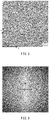
- a microstructure image with dimensions of 1 mm ⁇ 1 mm at an observation magnification of 100 times is taken of a cut surface perpendicular to an arbitrary plate-width direction of a stainless steel by picturing it by optical microscopy and rendering it using gray scale (256 levels).
- FIG. 1 One example of a microstructure image is shown in FIG. 1 .
- the microstructure image is positioned in an x-y coordinate system.
- the y-axis in FIG. 1 represents the length direction while the x-axis represents the wall-thickness direction, perpendicular to the length direction.
- a gray portion represents a substantially martensitic phase
- a white portion located between grains of the substantially martensitic phase represents ferrite.
- F(u,v) is the two-dimensional frequency spectrum of the two-dimensional data f(x,y) after the two-dimensional discrete Fourier transform.
- the frequency spectrum F(u,v) is typically a complex number, and contains information about the periodicity and regularity of the two-dimensional data f(x,y).
- the frequency spectrum F(u,v) contains information about the periodicity and regularity of the structure of the ferritic phase and substantially martensitic phase in a microstructure image such as that shown in FIG. 1 .
- FIG. 2 is a logarithmic frequency spectrogram from the microstructure image of FIG. 1 .
- the horizontal axis of FIG. 2 forms the v-axis, while the vertical axis forms the u-axis.
- the frequency spectrogram of FIG. 2 is a black/white gray-level image (i.e. gray-scale image), where the maximum value of frequency spectrum is white and the minimum value is black.
- a portion with higher frequency spectrum values i.e. white portion in FIG. 2
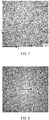
- FIG. 4 is a logarithmic frequency spectrogram from the microstructure image of FIG. 3
- FIG. 6 is a logarithmic frequency spectrogram from the microstructure image of FIG. 5
- FIG. 8 is a logarithmic frequency spectrogram from the microstructure image of FIG. 7 .
- the microstructure of FIG. 1 will be referred to as structure 1
- the microstructure of FIG. 3 will be referred to as structure 2
- the microstructure of FIG. 5 will be referred to as structure 3
- the microstructure of FIG. 7 will be referred to as structure 4.
- a comparison between the image of structure 1 ( FIG. 1 ) and the image of structure 2 ( FIG. 3 ) shows that structure 1 has a ferritic phase and substantially martensitic phase extending along the rolling direction (i.e. length direction) compared with structure 2. Further, in structure 1, the lamination period of the ferritic phase and substantially martensitic phase (i.e. period in which they are arranged in the wall-thickness direction) is shorter than in structure 2, and these phases are more regular.
- a comparison between the image of structure 1 and the image of structure 3 ( FIG. 5 ) shows that both structures 1 and 3 have each phase extending along the length direction. Further, similar to structure 1, structure 3 has a shorter lamination period and more regular phases.
- a comparison between the image of structure 3 and the image of structure 4 ( FIG. 7 ) shows that structure 3 has each phase extending along the length direction compared with structure 4. Further, structure 3 has a shorter lamination period and more regular phases than structure 4.
- a white portion extends along the u-axis.
- the width of the white portion measured in the v-axis direction, is smaller than in structures 2 and 4.
- the value of ⁇ is 2.024 in structure 1, 1.458 in structure 2, 2.183 in structure 3, and 1.395 in structure 4.
- the white portion becomes shorter as measured in the u-axis direction and broader as measured in the v-axis direction.
- FIG. 9 is a graph illustrating the relationship between ⁇ and the transition temperature (°C).
- FIG. 9 was created by the following procedure: A plurality of stainless steels with chemical compositions within the ranges of the present embodiment described below and with different values of ⁇ were produced. For each stainless steel, the low-temperature toughness evaluation test described below was conducted to obtain a transition temperature value, and FIG. 9 was created based on these values. The straight line in FIG. 9 was obtained by the method of least squares from all the plot points in FIG. 9 , where R 2 is a correlation function.
- ⁇ may be increased by hot rolling the steel material with a large fraction of austenite at the temperature for hot rolling and with a high reduction of sectional area.
- the fraction of austenite at the temperature for hot rolling may be increased by adjusting the chemical composition of the steel material or lowering the temperature of the hot rolling.
- the temperature for hot rolling is too low, hot workability decreases, which may cause flaws on the surface of the steel material.
- the chemical composition may be adjusted to increase the fraction of austenite at the temperature for hot rolling by increasing the contents of austenite-forming elements such as C, Ni, Cu and Co or reducing the contents of ferrite-forming elements such as Si, Cr, V, Mo and W. It is particularly effective to increase the Ni content. This makes ⁇ equal to or greater than 1.55 while the rolling temperature and reduction of sectional area are in a parctical range.
- the chemical composition is adjusted to increase the fraction of austenite at the temperature for hot rolling, the fraction of austenite at room temperature, i.e. the amount of retained austenite tends to be large. This makes it difficult to provide a required strength.
- V is contained in the steel material.
- V is a ferrite-forming element, and is thus disadvantageous when the fraction of austenite at the temperature for hot rolling is to be increased.
- V increases temper softening resistance to improve the strength of the steel.
- An appropriate V content makes it possible to make ⁇ equal to or greater than 1.55 and, at the same time, provide a required strength.
- the present inventors made the present invention based on the above-described findings. First, a summary of an embodiment of the present invention will be provided.
- a stainless steel according to an embodiment of the present invention has a chemical composition including, in mass%: C: 0.001 to 0.06 %; Si: 0.05 to 0.5 %; Mn: 0.01 to 2.0 %; P: up to 0.03 %; S: less than 0.005 %; Cr: 15.5 to 18.0 %; Ni: 2.5 to 6.0 %; V: 0.005 to 0.25 %; Al: up to 0.05 %; N: up to 0.06 %; O: up to 0.01 %; Cu: 0 to 3.5 %; Co: 0 to 1.5 %; Nb: 0 to 0.25 %; Ti: 0 to 0.25 %; Zr: 0 to 0.25 %; Ta: 0 to 0.25 %; B: 0 to 0.005 %; Ca: 0 to 0.01 %; Mg: 0 to 0.01 %; and REM: 0 to 0.05 %.
- the stainless steel has a matrix structure having, by volume ratio, 40 to 80 % tempered martensite, 10 to 50 % ferrite and 1 to 15 % austenite.
- ⁇ defined by Equation (2) is not smaller than 1.55: 1.0 ⁇ Mo + 0.5 W ⁇ 3.5
- Equation (5) f(x,y) represents the gray level of the pixel at coordinates (x,y).
- ⁇ is not lower than 1.55 such that the transition temperature for ductile brittleness is not higher than -30 °C.
- this stainless steel has good low-temperature toughness. Further, this stainless steel has high strength and good SCC resistance at high temperatures and good SSC resistance at room temperature.
- the chemical composition of the stainless steel in an embodiment of the present invention may include one or two selected from the group consisting of, in mass%: Cu: 0.2 to 3.5 %; and Co: 0.05 to 1.5 %.
- the chemical composition of the stainless steel in an embodiment of the present invention may include one or more selected from the group consisting of, in mass%: Nb: 0.01 to 0.25 %; Ti: 0.01 to 0.25 %; Zr: 0.01 to 0.25 %; and Ta: 0.01 to 0.25 %.
- the chemical composition of the stainless steel in an embodiment of the present invention may include one or more selected from the group consisting of, in mass%: B: 0.0003 to 0.005 %; Ca: 0.0005 to 0.01 %; Mg: 0.0005 to 0.01 %; and REM: 0.0005 to 0.05 %.
- the stainless steel in an embodiment of the present invention is used as a steel product for an oil well.
- the stainless steel in an embodiment of the present invention has the chemical composition described below.
- "%" for an element means mass percentage.
- Carbon (C) increases the strength of steel. However, if the C content is too high, the hardness after tempering is too high, decreasing SSC resistance. Further, in the chemical composition of the present embodiment, the Ms point falls as the C content increases. As such, as the C content increases, austenite tends to increase and yield strength tends to decrease. In view of this, the C content should be not higher than 0.06 %.
- the C content is preferably not higher than 0.05 %, and more preferably not higher than 0.03 %. Further, when the costs associated with the decarburization step in the steel-making process are considered, the C content should be not lower than 0.001 %.
- the C content is preferably not lower than 0.003 %, and more preferably not lower than 0.005 %.
- Si deoxidizes steel. However, if the Si content is too high, the toughness and hot workability of the steel decrease. Further, if the Si content is too high, the amount of ferrite produced increases and yield strength tends to decrease. Further, it becomes difficult to increase ⁇ . In view of this, the Si content should be in the range of 0.05 to 0.5 %.
- the Si content is preferably lower than 0.5 %, and more preferably not higher than 0.4 %.
- the Si content is preferably not lower than 0.06 %, and more preferably not lower than 0.07 %.
- Mn Manganese deoxidizes and desulfurizes steel, increasing hot workability. These effects are not sufficiently present if the Mn content is too low. On the other hand, if the Mn content is too high, excess austenite tends to remain during quenching, making it difficult to maintain the strength of the steel. In view of this, the Mn content should be in the range of 0.01 to 2.0 %.
- the Mn content is preferably not higher than 1.0 %, and more preferably not higher than 0.6 %.
- the Mn content is preferably not lower than 0.02 %, and more preferably not lower than 0.04 %.
- Phosphorus (P) is an impurity. P decreases the SSC resistance of steel. Thus, the lower the P content, the better.
- the P content should be not higher than 0.03 %.
- the P content is preferably not higher than 0.028 %, and more preferably not higher than 0.025 %. Although it is preferable to reduce the P content to the lowest possible level, reducing it excessively leads to increased steel-making costs.
- the P content is preferably not lower than 0.0005 %, and more preferably not lower than 0.0008 %.
- S Sulfur
- S is an impurity. S decreases the hot workability of steel. Thus, the lower the S content, the better.
- the S content should be lower than 0.005 %.
- the S content is preferably not higher than 0.003 %, and more preferably not higher than 0.0015 %. Although it is preferable to reduce the S content to the lowest possible level, reducing it excessively leads to increased steel-making costs. Thus, the S content is preferably not lower than 0.0001 %, and more preferably not lower than 0.0003 %.
- Chromium (Cr) increases the corrosion resistance of steel. More specifically, Cr decreases the corrosion rate, thereby increasing the SCC resistance of the steel. These effects are not sufficiently present if the Cr content is too low. On the other hand, if the Cr content is too high, the volume ratio of ferrite in the steel increases, decreasing the strength of the steel. Further, it becomes difficult to increase ⁇ . In view of this, the Cr content should be in the range of 15.5 to 18.0 %.
- the Cr content is preferably not higher than 17.8 %, and more preferably not higher than 17.5 %.
- the Cr content is preferably not lower than 16.0 %, and more preferably not lower than 16.3 %.
- Nickel (Ni) increases the toughness of steel. Further, Ni increases the strength of the steel. Ni increases the fraction of austenite at temperatures for hot working and contributes to increasing ⁇ . These effects are not sufficiently present if the Ni content is too low. On the other hand, if the Ni content is too high, a large amount of retained austenite tends to be produced, decreasing the strength of the steel. In view of this, the Ni content should be in the range of 2.5 to 6.0 %. The Ni content is preferably lower than 6.0 %, and more preferably not higher than 5.9 %. The Ni content is preferably not lower than 3.0 %, and more preferably not lower than 3.5 %.
- V 0.005 to 0.25 %
- Vanadium (V) increases the strength of steel. If the V content is lower than 0.005 %, a required strength cannot be provided. However, if the V content is too high, toughness decreases. Further, it becomes difficult to increase ⁇ . In view of this, the V content should be in the range of 0.005 to 0.25 %.
- the V content is preferably not higher than 0.20 %, and more preferably not higher than 0.15 %.
- the V content is preferably not lower than 0.008 %, and more preferably not lower than 0.01 %.
- the Al content is preferably not higher than 0.048 %, and more preferably not higher than 0.045 %.
- the Al content is preferably not lower than 0.0005 %, and more preferably not lower than 0.001 %.
- N Nitrogen
- the N content is preferably not higher than 0.05 %, and more preferably not higher than 0.03 %.
- the N content is preferably not lower than 0.001 %, and more preferably not lower than 0.002 %.
- Oxygen (O) is an impurity. O decreases the toughness and corrosion resistance of steel. In view of this, the O content should be not higher than 0.01 %.
- the O content is preferably lower than 0.01 %, and more preferably not higher than 0.009 %, and still more preferably not higher than 0.006 %. Although it is preferable to reduce the O content to the lowest possible level, reducing it excessively leads to increased steel-making costs. Thus, the O content is preferably not lower than 0.0001 %, and more preferably not lower than 0.0003 %.
- Molybdenum (Mo) and tungsten (W) are replaceable with each other, i.e. both of them may be contained or one of them may be contained. At least one of Mo and W must be contained. These elements increase the SCC resistance of the steel. On the other hand, if the contents of these elements are too high, the steel is saturated with them with respect to their effects, and it becomes difficult to increase ⁇ , as well.
- the Mo content should be in the range of 0 to 3.5 %
- the W content should be in the range of 0 to 3.5 %, and one or two selected from the group consisting of Mo and W must be contained in an amount that satisfies Equation (1).
- the Mo content is preferably not higher than 3.3 %, and more preferably not higher than 3.0 %.
- the Mo content is preferably not lower than 0.01 %, and more preferably not higher than 0.03 %.
- the W content is preferably not higher than 3.3 %, and more preferably not higher than 3.0 %.
- the W content is preferably not lower than 0.01 %, and more preferably not lower than 0.03 %.
- the chemical composition of the stainless steel in the present embodiment may contain one or more of the optional elements listed below. That is, each of the elements below does not have to be contained in the stainless steel in the present embodiment. Only some of them may be contained.
- Copper (Cu) and Cobalt (Co) are replaceable with each other. These elements are optional. These elements increase the volume fraction of tempered martensite, increasing the strength of the steel. Further, Cu contributes to increasing ⁇ . Further, during tempering, Cu precipitates in the form of Cu particles, further increasing the strength. These effects are not sufficiently present if the contents of these elements are too low. On the other hand, if the contents of these elements are too high, the hot workability of the steel decreases. In view of this, the Cu content should be in the range of 0 to 3.5 %, and the Co content should be in the range of 0 to 1.5 %.
- the Cu content is preferably not higher than 3.3 %, and more preferably not higher than 3.0 %.
- the Cu content is preferably not lower than 0.3 %, and more preferably not lower than 0.5 %.
- the Co content is preferably not higher than 1.0 %, and more preferably not higher than 0.8 %.
- the Co content is preferably not lower than 0.08 %, and more preferably not lower than 0.1 %.
- Nb 0 to 0.25 %
- Ti 0 to 0.25 %
- Zr 0 to 0.25 %
- Ta 0 to 0.25 %
- Niobium (Nb), titanium (Ti), zirconium (Zr) and tantalum (Ta) are replaceable with each other. These elements are optional. These elements increase the strength of steel. These elements improve the pitting resistance and SCC resistance of the steel. These effects are present if these elements are contained in a small amount. However, if the contents of these elements are too high, the toughness of the steel decreases. In view of this, the Nb content should be in the range of 0 to 0.25 %, the Ti content in the range of 0 to 0.25 %, the Zr content in the range of 0 to 0.25 %, and the Ta content in the range of 0 to 0.25 %.
- Nb 0.01 to 0.25 %
- Ti 0.01 to 0.25 %
- Zr 0.01 to 0.25 %
- Ta 0.01 to 0.25 %
- the Nb content is preferably not higher than 0.23 %, and more preferably not higher than 0.20 %.
- the Nb content is preferably not lower than 0.02 %, and more preferably not lower than 0.05 %.
- the Ti content is preferably not higher than 0.23 %, and more preferably not higher than 0.20 %.
- the Ti content is preferably not lower than 0.02 %, and more preferably not lower than 0.05 %.
- the Zr content is preferably not higher than 0.23 %, and more preferably not higher than 0.20 %.
- the Zr content is preferably not lower than 0.02 %, and more preferably not lower than 0.05 %.
- the Ta content is preferably not higher than 0.24 %, and more preferably not higher than 0.23 %.
- the Ta content is preferably not lower than 0.02 %, and more preferably not lower than 0.05 %.
- Ca Calcium
- Mg magnesium
- REMs rare-earth elements
- B boron
- the Ca content should be in the range of 0 to 0.01 %, the Mg content in the range of 0 to 0.01 %, the REM content in the range of 0 to 0.05 %, and the B content in the range of 0 to 0.005 %. It is preferable to include one or more selected from the group consisting of 0.0005 to 0.01 % Ca, 0.0005 to 0.01 % Mg, 0.0005 to 0.05 % REM and 0.0003 to 0.005 % B in order that the above-described effects are sufficiently present.
- the Ca content is preferably not higher than 0.008 %, and more preferably not higher than 0.005 %.
- the Ca content is preferably not lower than 0.0008 %, and more preferably not lower than 0.001 %.
- the Mg content is preferably not higher than 0.008 %, and more preferably not higher than 0.005 %.
- the Mg content is preferably not lower than 0.0008 %, and more preferably not lower than 0.001 %.
- the REM content is preferably not higher than 0.045 %, and more preferably not higher than 0.04 %.
- the REM content is preferably not lower than 0.0008 %, and more preferably not lower than 0.001 %.
- the B content is preferably not higher than 0.0045 %, and more preferably not higher than 0.004 %.
- the B content is preferably not lower than 0.0005 %, and more preferably not lower than 0.0008 %.
- REM is a general term for a total of 17 elements, i.e. scandium (Sc), yttrium (Y) and lanthanoids.
- REM content means the total content of one or more of these 17 elements.
- the balance of the chemical composition of the stainless steel in the present embodiment is Fe and impurities.
- Impurity as used herein means an element originating from ore or scraps used as a raw material of a stainless steel being manufactured on an industrial basis or an element that has entered from the environment or the like during the manufacturing process.
- the matrix structure of the stainless steel in the present embodiment has, in volume ratio, 40 to 80 % tempered martensite, 10 to 50 % ferrite, and 1 to 15 % austenite.
- "%" for the volume ratios (or fractions) for the matrix structure means volume percentage.
- the lower limit of the volume ratio of tempered martensite is preferably 45 %, and more preferably 50 %.
- the upper limit of the volume ratio of tempered martensite is preferably 75 %, and more preferably 70 %.
- the lower limit of the volume ratio of ferrite is preferably 15 %, and more preferably 20 %.
- the upper limit of the volume ratio of ferrite is preferably 45 %, and more preferably 40 %.
- the lower limit of the volume ratio of austenite is preferably 1.5 %, and more preferably 2 %.
- the upper limit of the volume ratio of austenite is preferably 12 %, and more preferably 10 %.
- austenite-forming elements such as C, Ni, Cu and Co are increased, the volume ratios of tempered martensite and austenite increase and the volume ratio of ferrite decreases. If the contents of ferrite-forming elements such as Si, Cr, V, Mo and W are increased, the volume ratio of ferrite increases and the volume ratios of tempered martensite and austenite decrease.
- the volume ratio of ferrite in the matrix structure i.e. ferrite fraction, in %), the volume ratio of austenite (i.e. austenite fraction, in %) and the volume ratio of tempered martensite (i.e. martensite fraction, in %) are measured by the following procedure.
- a sample is extracted from an arbitrary location in a stainless steel.
- the surface of the sample that corresponds to a cut surface of the stainless steel (hereinafter referred to as observed surface) is polished.
- a mixed solution of aqua regia and glycerin is used to etch the observed surface that has been polished.
- the portions that have been etched and become white constitute a ferritic phase, and the area ratio of this ferritic phase is measured by point counting in accordance with JIS G0555 (2003). Since it is assumed that the measured area ratio is equal to the volume fraction of the ferritic phase, ferrite fraction (%) is defined as such an area ratio.
- Austenite fraction is determined using the X-ray diffraction method.
- a sample with dimensions of 15 mm ⁇ 15 mm ⁇ 2 mm is extracted from an arbitrary location of a stainless steel.
- the X-ray intensities for the (200) and (211) planes of the ferritic phase ( ⁇ phase) and the (200), (220) and (311) planes of the austenitic phase (y phase) are measured and the integrated intensity for each plane is calculated.
- Equation (6) provided below is used to determine the volume ratio V ⁇ .
- Austenite fraction (%) is defined as the average of the volume ratios V ⁇ for these planes.
- V ⁇ 100 / 1 + I ⁇ ⁇ R ⁇ ⁇ I ⁇ ⁇ R ⁇
- I ⁇ is the integrated intensity for the ⁇ phase
- R ⁇ is the crystallographic theoretical calculated value for the ⁇ phase
- I ⁇ is the integrated intensity for the ⁇ phase
- R ⁇ is the crystallographic theoretical calculated value for the ⁇ phase.
- volume ratio of the tempered martensitic phase is defined as the volume ratio of the remainder of the matrix structure, i.e. the portion thereof other than ferrite and austenite. That is, the martensite fraction (%) is obtained by subtracting the ferrite fraction (%) and austenite fraction (%) from 100 %.
- the stainless steel in the present embodiment has a value of ⁇ defined by Equation (2) that is equal to or larger than 1.55.
- ⁇ is calculated by the following procedure. A matrix structure on a cut surface perpendicular to an arbitrary plate-width direction of a stainless steel (for a steel pipe, a cut surface in the wall thickness parallel to the pipe axis) is photographed at a magnification of 100 times. The obtained microstructure image with dimensions of 1 mm ⁇ 1mm is positioned in an x-y coordinate system with an x-axis extending in the wall-thickness direction and a y-axis extending in the length direction, and each of 1024 ⁇ 1024 pixels is represented by a gray scale level.
- Equation (5) F(u,v) is defined by Equation (5).
- Equation (5) f(x,y) represents the gray level of the pixel at coordinates (x,y).
- ⁇ and low-temperature toughness are in the relationship shown in FIG. 9 .
- the transition temperature for ductile brittleness is not higher than -30 °C, as shown in FIG. 9 , if the value of ⁇ calculated from a matrix structure is not lower than 1.55.
- the stainless steel in an embodiment of the present invention has good low-temperature toughness at -10 °C, to which temperature the steel is typically required to be exposed.
- the value of ⁇ is preferably not lower than 1.6, and more preferably not lower than 1.65.
- ⁇ is dependent on the austenite fraction at temperatures for hot working and the reduction of sectional area. The higher the austenite fraction at temperatures for hot working and the higher the reduction of sectional area, the greater ⁇ becomes.
- the austenite fraction at temperatures for hot working may be increased by increasing the contents of austenite-forming elements such as C, Ni, Cu and Co or reducing the contents of ferrite-forming elements such as Si, Cr, V, Mo and W. Or, hot working may be performed at lower temperatures.
- the stainless steel in an embodiment of the present invention has high strength and good SCC resistance at high temperatures and good SSC resistance at room temperature, and has good low-temperature toughness.
- the stainless steel in the present embodiment is used as a stainless steel product for an oil well.
- the stainless steel according to the present embodiment has a yield strength not lower than 758 MPa. More preferably, the stainless steel according to the present embodiment has a yield strength not lower than 800 MPa.
- the stainless steel according to the present embodiment has a transition temperature for ductile brittleness not higher than -30 °C. More preferably, the stainless steel according to the present embodiment has a transition temperature for ductile brittleness not higher than -35 °C.
- a matrix structure with a value of ⁇ not lower than 1.55 will be obtained if a steel material having the above-described chemical composition (slab or billet such as a slab, bloom or billet) is hot-rolled at an appropriate temperature at the highest possible reduction of sectional area.
- a method of manufacturing a stainless steel a method of manufacturing a stainless steel plate will be described.
- a steel material having the above-described chemical composition is prepared.
- the material may be a slab produced by continuous casting, or a plate produced by hot-working a slab or ingot.
- the prepared material is loaded into a heating furnace or soaking furnace and is heated.
- the heated material is hot-rolled to produce an intermediate material (i.e. steel material after hot-rolling).
- the reduction of sectional area during this hot-rolling step is 40 % or higher.
- the steel material temperature during hot rolling is in the range of 1200 to 1300 °C.
- Steel material temperature as used herein means the temperature of the surface of the material. The temperature of the surface of the material may be measured at the time when the hot rolling begins, for example. The temperature of the surface of the material is the average of surface temperatures measured along the axial direction of the material. If the material is soaked at a heating temperature of 1250 °C in the heating furnace, for example, the steel material temperature is substantially equal to the heating temperature, i.e. 1250 °C.
- the steel material temperature when the hot rolling ends is preferably not lower than 1100 °C.
- the reduction of sectional area is the cumulative reduction for the hot-rolling steps consecutively performed on a material at steel material temperatures in the range of 1100 to 1300 °C.
- the steel material temperature falls below 1100 °C during hot rolling, the resulting decrease in hot workability may produce a large number of flaws on the steel material surface.
- the higher the heating temperature for the steel material the better.
- the material plate after hot rolling i.e. intermediate material
- the material plate after hot rolling i.e. intermediate material
- quenching and tempering the intermediate material ensures that the yield strength of the stainless steel plate is not lower than 758 MPa.
- the matrix structure has tempered martensite and ferrite phase.
- the intermediate material is cooled to a temperature close to room temperature. Then, the cooled intermediate material is heated to a temperature in the range of 850 to 1050 °C. The heated intermediate material is cooled by water or the like, and is quenched to produce a stainless steel plate.
- the intermediate material after quenching is heated to a temperature that is not higher than 650 °C. That is, the tempering temperature is preferably not higher than 650 °C, because, if the tempering temperature exceeds 650 °C, austenite phase retained at room temperature increases in the steel, which tends to decrease strength.
- the intermediate material after quenching is heated to a temperature higher than 500 °C. That is, the tempering temperature is preferably higher than 500 °C.
- the manufacturing process described above produces a stainless steel plate with ⁇ not lower than 1.55.
- the stainless steel is not limited to a steel plate and may take other shapes.
- the material is soaked at a temperature in the range of 1200 to 1250 °C for a predetermined period of time, and hot rolling is then performed at a reduction of sectional area not lower than 50 % and at a rolling end temperature not lower than 1100 °C. This will provide a stainless steel product with high degree of layeredness while preventing production of surface flaws.
- Steels of steel types A to W having the chemical compositions shown in Table 1 were produced by smelting, and ingots were produced.
- the chemical compositions of steel types A to V are within the ranges of the present embodiment.
- Steel type W is a comparative example that contains no V.
- the ingots were hot-forged to produce plates with a width of 100 mm and a height of 30 mm.
- the produced plates were treated to provide steel materials of Nos. 1 to 37.
- the content of each element is in mass percentage and the balance is Fe and impurities.
- Steel type Chemical composition (in mass %.
- the materials prepared were heated in a heating furnace.
- the heated materials were removed from the heating furnace and, immediately after the removal, were subjected to hot rolling to produce intermediate materials of Nos. 1 to 37.
- the steel material temperatures for the materials during hot rolling are shown in Table 2.
- the materials were heated in the heating furnace for a sufficient time period such that the steel material temperatures were equal to the heating temperatures.
- the reductions of sectional area during hot rolling for the various numbers are shown in Table 2. [Table 2] No.
- the intermediate materials of Nos. 1 to 37 were quenched and tempered.
- the quenching temperature was 950 °C.
- the time for which the materials were held at the quenching temperature (i.e. heat-treatment time) was 15 minutes.
- the intermediate materials were quenched by water cooling.
- the tempering temperature for the intermediate materials of Nos. 1, 23 to 30, 32, 33 and 37 was 550 °C, and that for the intermediate materials of Nos. 2 to 22, 31 and 34 to 36 was 600 °C.
- the time for which the materials were held at the tempering temperature was 30 minutes.
- the above-described manufacturing process produced the steel plates of the various numbers.
- the steel plates of Nos. 1 to 37 were cut at the center as measured in the width along the length direction.
- Samples for microstructure observation were extracted from the portions of the cut surfaces (with a y-axis formed by the length direction and an x-axis formed by the wall-thickness direction) that were located at the centers of the steel plates.
- the area ratio was measured on each of the extracted samples by the procedure described above, and treated as the volume ratio of ferrite.
- the volume ratio of austenite was calculated by the X-ray diffraction method described above.
- the volume ratio of tempered martensite was calculated by the procedure described above using the volume ratio of ferrite and the volume ratio of austenite.
- microstructure image of dimensions of 1 mm ⁇ 1mm at an observation magnification of 100 times was obtained from an arbitrary location on each observed surface.
- the obtained microstructure image was used to calculate the value of ⁇ for each of the steel plates of the various numbers by the procedure described above.
- a round rod for a tensile test was extracted from the portion of each of the steel plates of Nos. 1 to 37 that was located at the center as measured in the wall-thickness direction.
- the longitudinal direction of the round rod was parallel to the rolling direction for the steel plate (i.e. L direction).
- the diameter of the parallel portion of each round rod was 6 mm, and the distance between the gauge marks was 40 mm.
- a tensile test was conducted for each extracted round rod in accordance with JIS Z 2241 (2011) at room temperature to determine the yield strength (0.2 % proof stress).
- Charpy impact tests were conducted to evaluate toughness at low-temperatures.
- a full-size test specimen in accordance with ASTM E23 was extracted from the portion of each of the steel plates of Nos. 1 to 37 that was located at the center as measured in the wall-thickness direction. The longitudinal direction of the test specimens was parallel to the plate width direction.
- a Charpy impact test was conducted for each of the extracted test specimens at temperatures in the range of 20 °C to -120 °C, and the absorbed energy (J) was measured and the ductility-brittleness transition temperature for impact absorbed energy was determined.
- a four-point bending test specimen was extracted from each of the steel plates of Nos. 1 to 37.
- the test specimens had a length of 75 mm, a width of 10 mm and a thickness of 2 mm.
- the test specimens were deflected by four-point bending. The amount of deflection for each test specimen was determined such that the stress applied to the test specimen was equal to the 0.2 % offset proof stress of the test specimen in accordance with ASTM G 39.
- An autoclave at 200 °C in which CO 2 at 30 bar (3.0 MPa) and H 2 S at 0.01 bar (1 kPa) were sealed under pressure was provided for each of Nos. 1 to 36.
- a deflected test specimen was placed within each autoclave.
- test specimen was immersed for 720 hours in an NaCl solution of 25 mass%.
- the solution was adjusted to pH 4.5 by a CH 3 COONa+CH 3 COOH buffer system containing 0.41 g/l of CH 3 COONa.
- SCC stress corrosion cracks
- a cut surface of the test specimen to which the tensile stress had been applied was observed by optical microscopy at a magnification of 100 times to determine whether there were cracks.
- " ⁇ " indicates that there were no cracks and " ⁇ " indicates that there were cracks, and the test specimens with " ⁇ " had better SCC resistances than those with " ⁇ ”.
- the decrease in amount due to corrosion for each test specimen was determined based on the difference between the weight before the test and the weight after the immersion. Based on the determined decrease in amount due to corrosion, the annual corrosion amount (mm/year) was calculated.
- a round rod test specimen was extracted for NACE TM0177 METHOD A.
- the test specimen had a diameter of 6.35 mm, and a parallel portion length of 25.4 mm.
- a tensile stress was applied to the test specimen in its axial direction.
- the stress applied to the test specimen was adjusted so as to be 90 % of the measured yield stress of the test specimen in accordance with NACA TM0177-2005.
- the test specimen was immersed for 720 hours in an NaCl solution of 25 mass% saturated with H 2 S at 0.01 bar (1 kPa) and CO 2 at 0.99 bar (0.099 MPa).
- the solution was adjusted to pH 4.0 by a CH 3 COONa+CH 3 COOH buffer system containing 0.41 g/l of CH 3 COONa.
- the temperature of the solution was adjusted to 25 °C.
- the test specimen after immersion was observed to determine whether there were sulfide stress corrosion cracks (SSC). More specifically, those of the test specimens of Nos. 1 to 37 that broke during the test and those that did not break were examined, where the parallel portion of each test specimen was observed by the naked eye to determine whether there were cracks or pits.
- SSC sulfide stress corrosion cracks
- Table 3 shows the test results.
- the volume ratio of ferrite ( ⁇ fraction), the volume ratio of austenite ( ⁇ fraction) and the volume ratio of tempered martensite (M fraction) were within the ranges of the present embodiment.
- Each of the steel materials of Nos. 1 to 36 had a yield strength not less than 758 MPa, an annual corrosion amount not higher than 0.01 mm/year, and good SCC resistance and SSC resistance. [Table 3] No.
- ⁇ was not less than 1.55, but the yield strength was lower than 758 MPa.
- the present invention provides a stainless steel having high strength and good SSC resistance at room temperature and good low-temperature toughness which is suitable for use in an oil well.
Landscapes
- Chemical & Material Sciences (AREA)
- Engineering & Computer Science (AREA)
- Materials Engineering (AREA)
- Mechanical Engineering (AREA)
- Metallurgy (AREA)
- Organic Chemistry (AREA)
- Physics & Mathematics (AREA)
- Thermal Sciences (AREA)
- Crystallography & Structural Chemistry (AREA)
- Heat Treatment Of Steel (AREA)
Applications Claiming Priority (2)
| Application Number | Priority Date | Filing Date | Title |
|---|---|---|---|
| JP2015154360 | 2015-08-04 | ||
| PCT/JP2016/069241 WO2017022374A1 (ja) | 2015-08-04 | 2016-06-29 | ステンレス鋼及び油井用ステンレス鋼材 |
Publications (2)
| Publication Number | Publication Date |
|---|---|
| EP3333276A1 true EP3333276A1 (de) | 2018-06-13 |
| EP3333276A4 EP3333276A4 (de) | 2019-01-09 |
Family
ID=57942875
Family Applications (1)
| Application Number | Title | Priority Date | Filing Date |
|---|---|---|---|
| EP16832653.6A Withdrawn EP3333276A4 (de) | 2015-08-04 | 2016-06-29 | Edelstahl und ölbohrlochedelstahlmaterial |
Country Status (11)
| Country | Link |
|---|---|
| US (1) | US10378079B2 (de) |
| EP (1) | EP3333276A4 (de) |
| JP (1) | JP6432683B2 (de) |
| CN (1) | CN107849661B (de) |
| AR (1) | AR105570A1 (de) |
| AU (1) | AU2016302517B2 (de) |
| BR (1) | BR112017020184A2 (de) |
| CA (1) | CA2980889C (de) |
| MX (1) | MX2017012752A (de) |
| RU (1) | RU2686727C2 (de) |
| WO (1) | WO2017022374A1 (de) |
Cited By (2)
| Publication number | Priority date | Publication date | Assignee | Title |
|---|---|---|---|---|
| EP4012053A4 (de) * | 2019-10-01 | 2022-10-12 | JFE Steel Corporation | Nahtloses rohr aus edelstahl und verfahren zur herstellung davon |
| EP4108797A4 (de) * | 2020-04-01 | 2024-09-25 | JFE Steel Corporation | Hochfestes nahtloses edelstahlrohr für ölbohrloch und verfahren zur herstellung davon |
Families Citing this family (14)
| Publication number | Priority date | Publication date | Assignee | Title |
|---|---|---|---|---|
| KR101747094B1 (ko) * | 2015-12-23 | 2017-06-15 | 주식회사 포스코 | 삼상 스테인리스강 및 그 제조방법 |
| JP7264596B2 (ja) * | 2018-03-19 | 2023-04-25 | 日本製鉄株式会社 | 鋼材 |
| BR112020015629B1 (pt) * | 2018-03-30 | 2023-12-05 | Nippon Steel Stainless Steel Corporation | Aço inoxidável ferrítico com excelente resistência à formação de estrias |
| CN109023072A (zh) * | 2018-09-04 | 2018-12-18 | 合肥久新不锈钢厨具有限公司 | 一种高稳定性耐腐蚀不锈钢及其制备方法 |
| WO2020071522A1 (ja) * | 2018-10-04 | 2020-04-09 | 日本製鉄株式会社 | 冷延鋼板 |
| CN111088459A (zh) * | 2019-12-31 | 2020-05-01 | 兴化市锐达建材机械有限公司 | 一种高强度耐腐蚀桥桩用不锈钢 |
| CN113584407A (zh) * | 2020-04-30 | 2021-11-02 | 宝山钢铁股份有限公司 | 一种高强度耐高温腐蚀马氏体不锈钢及其制造方法 |
| CN112281067A (zh) * | 2020-10-29 | 2021-01-29 | 东营市元捷石油机械有限公司 | 一种耐腐蚀钢材及其制备方法和应用 |
| CN112458370A (zh) * | 2020-12-01 | 2021-03-09 | 福州大学 | 一种含马氏体、铁素体和奥氏体的三相不锈钢 |
| CN114921723B (zh) * | 2022-05-20 | 2023-06-13 | 无锡双马钻探工具有限公司 | 一种非开挖钻杆用耐腐蚀钢材及其制备方法和用途 |
| CN115717221B (zh) * | 2022-11-17 | 2024-02-02 | 清华大学 | 强韧耐腐蚀三相不锈钢、其制备方法和不锈钢制品 |
| WO2024209843A1 (ja) | 2023-04-06 | 2024-10-10 | Jfeスチール株式会社 | ステンレス継目無鋼管およびその製造方法 |
| CN116790998A (zh) * | 2023-07-03 | 2023-09-22 | 北京科技大学 | 一种铁素体-马氏体-奥氏体三相不锈钢及其制备方法 |
| JP7730439B1 (ja) * | 2025-03-31 | 2025-08-27 | 日本冶金工業株式会社 | 二相ステンレス鋼、鋼板及び該鋼板の製造方法 |
Family Cites Families (22)
| Publication number | Priority date | Publication date | Assignee | Title |
|---|---|---|---|---|
| DE1533158B1 (de) * | 1965-06-22 | 1970-01-02 | Avesta Jernverks Ab | Verwendung eines walzbaren und schweissbaren nichtrostenden Stahles zur Herstellung von Gegenstaenden,die zum Einsatz unter Neutronenbestrahlung und bei Temperaturen zwischen -200 und +400 deg.C bestimmt sind,und als Schweisszusatzwerkstoff |
| JP4250851B2 (ja) * | 2000-03-30 | 2009-04-08 | 住友金属工業株式会社 | マルテンサイト系ステンレス鋼および製造方法 |
| WO2005007915A1 (ja) * | 2003-07-22 | 2005-01-27 | Sumitomo Metal Industries, Ltd. | マルテンサイト系ステンレス鋼 |
| JP5109222B2 (ja) * | 2003-08-19 | 2012-12-26 | Jfeスチール株式会社 | 耐食性に優れた油井用高強度ステンレス継目無鋼管およびその製造方法 |
| CN100451153C (zh) * | 2003-08-19 | 2009-01-14 | 杰富意钢铁株式会社 | 耐腐蚀性优良的油井用高强度不锈钢管及其制造方法 |
| EP1683885B1 (de) | 2003-10-31 | 2013-05-29 | JFE Steel Corporation | Rohr aus hochfestem nichtrostendem stahl mit hervorragender korrosionsbeständigkeit und herstellungsverfahren dafür |
| RU2321671C2 (ru) * | 2005-05-18 | 2008-04-10 | Зао "Ижевский Опытно-Механический Завод" | Нержавеющая сталь |
| MX365548B (es) * | 2007-11-29 | 2019-06-07 | Ati Properties Llc | Acero inoxidable austenitico pobre. |
| AU2009230545B2 (en) * | 2008-03-28 | 2011-12-15 | Nippon Steel Corporation | Stainless steel for use in oil well tube |
| AR073884A1 (es) | 2008-10-30 | 2010-12-09 | Sumitomo Metal Ind | Tubo de acero inoxidable de alta resistencia excelente en resistencia a la fisuracion bajo tension por sulfuros y a la corrosion de gas de acido carbonico en alta temperatura. |
| JP5446335B2 (ja) | 2009-03-10 | 2014-03-19 | Jfeスチール株式会社 | 油井用高強度ステンレス鋼管の評価方法 |
| AR076669A1 (es) * | 2009-05-18 | 2011-06-29 | Sumitomo Metal Ind | Acero inoxidable para pozos de petroleo, tubo de acero inoxidable para pozos de petroleo, y metodo de fabricacion de acero inoxidable para pozos de petroleo |
| CN102859019A (zh) * | 2010-04-19 | 2013-01-02 | 杰富意钢铁株式会社 | 焊接热影响部的耐晶间应力腐蚀开裂性优异的线管用含Cr钢管 |
| JP4911266B2 (ja) * | 2010-04-28 | 2012-04-04 | 住友金属工業株式会社 | 高強度油井用ステンレス鋼及び高強度油井用ステンレス鋼管 |
| JP5640762B2 (ja) * | 2011-01-20 | 2014-12-17 | Jfeスチール株式会社 | 油井用高強度マルテンサイト系ステンレス継目無鋼管 |
| AU2013238482B2 (en) | 2012-03-26 | 2015-07-16 | Nippon Steel Corporation | Stainless steel for oil wells and stainless steel pipe for oil wells |
| JP5488643B2 (ja) * | 2012-05-31 | 2014-05-14 | Jfeスチール株式会社 | 油井管用高強度ステンレス鋼継目無管およびその製造方法 |
| BR112016004849B1 (pt) * | 2013-09-04 | 2022-03-22 | Jfe Steel Corporation | Método de fabricação de um tubo de aço inoxidável de alta resistência e tubo de aço inoxidável de alta resistência |
| JP6171834B2 (ja) * | 2013-10-21 | 2017-08-02 | Jfeスチール株式会社 | 厚肉鋼材製造用装置列 |
| JP2015082352A (ja) * | 2013-10-21 | 2015-04-27 | 住友電装株式会社 | ワイヤーハーネス |
| JP6229794B2 (ja) * | 2015-01-15 | 2017-11-15 | Jfeスチール株式会社 | 油井用継目無ステンレス鋼管およびその製造方法 |
| BR112018000540B1 (pt) * | 2015-07-10 | 2022-03-03 | Jfe Steel Corporation | Tubo de aço inoxidável sem costura de alta resistência e método para a fabricação de tubo de aço inoxidável sem costura de alta resistência |
-
2016
- 2016-06-29 US US15/747,825 patent/US10378079B2/en active Active
- 2016-06-29 EP EP16832653.6A patent/EP3333276A4/de not_active Withdrawn
- 2016-06-29 RU RU2017135000A patent/RU2686727C2/ru active
- 2016-06-29 WO PCT/JP2016/069241 patent/WO2017022374A1/ja not_active Ceased
- 2016-06-29 JP JP2017532433A patent/JP6432683B2/ja active Active
- 2016-06-29 BR BR112017020184-4A patent/BR112017020184A2/pt not_active Application Discontinuation
- 2016-06-29 CA CA2980889A patent/CA2980889C/en not_active Expired - Fee Related
- 2016-06-29 AU AU2016302517A patent/AU2016302517B2/en not_active Ceased
- 2016-06-29 CN CN201680042985.1A patent/CN107849661B/zh active Active
- 2016-06-29 MX MX2017012752A patent/MX2017012752A/es unknown
- 2016-08-02 AR ARP160102350A patent/AR105570A1/es unknown
Cited By (4)
| Publication number | Priority date | Publication date | Assignee | Title |
|---|---|---|---|---|
| EP4012053A4 (de) * | 2019-10-01 | 2022-10-12 | JFE Steel Corporation | Nahtloses rohr aus edelstahl und verfahren zur herstellung davon |
| US12291766B2 (en) | 2019-10-01 | 2025-05-06 | Jfe Steel Corporation | Stainless steel seamless pipe and method for manufacturing same |
| EP4108797A4 (de) * | 2020-04-01 | 2024-09-25 | JFE Steel Corporation | Hochfestes nahtloses edelstahlrohr für ölbohrloch und verfahren zur herstellung davon |
| US12398436B2 (en) | 2020-04-01 | 2025-08-26 | Jfe Steel Corporation | High-strength stainless steel seamless pipe for oil country tubular goods and method for manufacturing same |
Also Published As
| Publication number | Publication date |
|---|---|
| CA2980889A1 (en) | 2017-02-09 |
| RU2017135000A (ru) | 2019-04-05 |
| AU2016302517B2 (en) | 2018-11-29 |
| US10378079B2 (en) | 2019-08-13 |
| RU2017135000A3 (de) | 2019-04-05 |
| JPWO2017022374A1 (ja) | 2017-12-14 |
| CN107849661B (zh) | 2020-05-15 |
| US20180209009A1 (en) | 2018-07-26 |
| WO2017022374A1 (ja) | 2017-02-09 |
| AR105570A1 (es) | 2017-10-18 |
| JP6432683B2 (ja) | 2018-12-05 |
| CA2980889C (en) | 2020-02-25 |
| MX2017012752A (es) | 2018-06-06 |
| RU2686727C2 (ru) | 2019-04-30 |
| EP3333276A4 (de) | 2019-01-09 |
| CN107849661A (zh) | 2018-03-27 |
| BR112017020184A2 (pt) | 2018-06-12 |
| AU2016302517A1 (en) | 2017-11-02 |
Similar Documents
| Publication | Publication Date | Title |
|---|---|---|
| EP3333276A1 (de) | Edelstahl und ölbohrlochedelstahlmaterial | |
| EP2434030B1 (de) | Edelstahl für ölbohrloch, edelstahlrohr für ölbohrloch und verfahren zur herstellung von edelstahl für ölbohrloch | |
| EP2832881B1 (de) | Rostfreier stahl für ölbohrungen und rostfreies stahlrohr für ölbohrungen | |
| JP4577457B2 (ja) | 油井管に用いられるステンレス鋼 | |
| EP2565287B1 (de) | Hochfester edelstahl für ein ölbohrloch und hochfestes edelstahlrohr für ein ölbohrloch | |
| EP3321389B1 (de) | Hochfestes nahtloses edelstahlrohr und herstellungsverfahren dafür | |
| EP2508639B1 (de) | Feinkörniges austenitisches edelstahlblech mit hervorragender belastungskorrosionsbruchfestigkeit und verarbeitbarkeit | |
| EP3153597B1 (de) | Rohr aus niedriglegiertem stahl für ölbohrloch | |
| EP2942414A1 (de) | Dicke, harte stahlplatte mit hoher zugfestigkeit und herstellungsverfahren dafür | |
| EP4286542B1 (de) | Martensitisches edelstahlmaterial | |
| WO2015072458A1 (ja) | Ni-Cr合金材およびそれを用いた油井用継目無管 | |
| EP3246418B1 (de) | Nahtloses edelstahlrohr für ein ölbohrloch und verfahren zur herstellung davon | |
| EP4023778B1 (de) | Stahlmaterial zur verwendung in einer sauren umgebung | |
| EP3591085B1 (de) | Nickelhaltige stahlplatte für den gebrauch bei niedriger temperatur und behälter für den gebrauch bei niedriger temperatur unter verwendung derselben | |
| JP6315076B2 (ja) | 油井用高強度ステンレス継目無鋼管の製造方法 | |
| EP4029962A1 (de) | Warmgewalztes stahlblech für elektrogeschweisste stahlrohre und verfahren zu deren herstellung, elektrogeschweisste stahlrohre und verfahren zu deren herstellung, leitungsrohre und baustruktur | |
| JP7381983B2 (ja) | マルテンサイト系ステンレス継目無鋼管、及び、マルテンサイト系ステンレス継目無鋼管の製造方法 |
Legal Events
| Date | Code | Title | Description |
|---|---|---|---|
| STAA | Information on the status of an ep patent application or granted ep patent |
Free format text: STATUS: THE INTERNATIONAL PUBLICATION HAS BEEN MADE |
|
| PUAI | Public reference made under article 153(3) epc to a published international application that has entered the european phase |
Free format text: ORIGINAL CODE: 0009012 |
|
| STAA | Information on the status of an ep patent application or granted ep patent |
Free format text: STATUS: REQUEST FOR EXAMINATION WAS MADE |
|
| 17P | Request for examination filed |
Effective date: 20170901 |
|
| AK | Designated contracting states |
Kind code of ref document: A1 Designated state(s): AL AT BE BG CH CY CZ DE DK EE ES FI FR GB GR HR HU IE IS IT LI LT LU LV MC MK MT NL NO PL PT RO RS SE SI SK SM TR |
|
| AX | Request for extension of the european patent |
Extension state: BA ME |
|
| DAV | Request for validation of the european patent (deleted) | ||
| DAX | Request for extension of the european patent (deleted) | ||
| A4 | Supplementary search report drawn up and despatched |
Effective date: 20181207 |
|
| RIC1 | Information provided on ipc code assigned before grant |
Ipc: C22C 38/50 20060101ALI20181203BHEP Ipc: C21D 1/25 20060101ALI20181203BHEP Ipc: C21D 1/18 20060101ALI20181203BHEP Ipc: C22C 38/04 20060101ALI20181203BHEP Ipc: C22C 38/52 20060101ALI20181203BHEP Ipc: C22C 38/46 20060101ALI20181203BHEP Ipc: C22C 38/42 20060101ALI20181203BHEP Ipc: C22C 38/00 20060101AFI20181203BHEP Ipc: C22C 38/54 20060101ALI20181203BHEP Ipc: C22C 38/02 20060101ALI20181203BHEP Ipc: C22C 38/48 20060101ALI20181203BHEP Ipc: C21D 9/46 20060101ALI20181203BHEP Ipc: C21D 6/00 20060101ALI20181203BHEP Ipc: C21D 8/02 20060101ALI20181203BHEP Ipc: C22C 38/44 20060101ALI20181203BHEP Ipc: C22C 38/06 20060101ALI20181203BHEP Ipc: C22C 38/58 20060101ALI20181203BHEP |
|
| RAP1 | Party data changed (applicant data changed or rights of an application transferred) |
Owner name: NIPPON STEEL CORPORATION |
|
| STAA | Information on the status of an ep patent application or granted ep patent |
Free format text: STATUS: EXAMINATION IS IN PROGRESS |
|
| 17Q | First examination report despatched |
Effective date: 20210120 |
|
| STAA | Information on the status of an ep patent application or granted ep patent |
Free format text: STATUS: THE APPLICATION HAS BEEN WITHDRAWN |
|
| 18W | Application withdrawn |
Effective date: 20210301 |