EP3332733A1 - Zweiteiliger adapter zum einbringen eines dentalimplantats - Google Patents
Zweiteiliger adapter zum einbringen eines dentalimplantats Download PDFInfo
- Publication number
- EP3332733A1 EP3332733A1 EP16203186.8A EP16203186A EP3332733A1 EP 3332733 A1 EP3332733 A1 EP 3332733A1 EP 16203186 A EP16203186 A EP 16203186A EP 3332733 A1 EP3332733 A1 EP 3332733A1
- Authority
- EP
- European Patent Office
- Prior art keywords
- adapter
- implant
- ring
- counter
- apical
- Prior art date
- Legal status (The legal status is an assumption and is not a legal conclusion. Google has not performed a legal analysis and makes no representation as to the accuracy of the status listed.)
- Granted
Links
Images








Classifications
-
- A—HUMAN NECESSITIES
- A61—MEDICAL OR VETERINARY SCIENCE; HYGIENE
- A61C—DENTISTRY; APPARATUS OR METHODS FOR ORAL OR DENTAL HYGIENE
- A61C8/00—Means to be fixed to the jaw-bone for consolidating natural teeth or for fixing dental prostheses thereon; Dental implants; Implanting tools
- A61C8/0089—Implanting tools or instruments
-
- A—HUMAN NECESSITIES
- A61—MEDICAL OR VETERINARY SCIENCE; HYGIENE
- A61C—DENTISTRY; APPARATUS OR METHODS FOR ORAL OR DENTAL HYGIENE
- A61C8/00—Means to be fixed to the jaw-bone for consolidating natural teeth or for fixing dental prostheses thereon; Dental implants; Implanting tools
- A61C8/0087—Means for sterile storage or manipulation of dental implants
Definitions
- the present invention describes a two-part adapter for introducing a dental implant into the bone, wherein the first part is an elongated adapter, at the apical part of which there is at least one snap closure, which in arrangement of the apical part of the adapter in a coronal recess of the dental implant in at least engages a complementary structure on the inside of the recess of the dental implant and produces a reversible plug connection between the adapter and dental implant, and the second part is a counter-ring, in the central recess of the apical part of the adapter is arranged.
- a dental implant is inserted into the human jawbone and serves as an artificial tooth root for attachment of prosthetic components such as prosthetic components. a body part or abutment.
- prosthetic components such as prosthetic components.
- a body part or abutment The use of dental implants as artificial replacement for tooth roots has become established in recent years.
- dental implants in particular, the helical implants have proven.
- Screw-shaped dental implants usually consist of an anchoring part for anchoring the implant in the bone and a mounting part on which a superstructure, for example a crown, can be fastened. If anchoring part and body part are formed as a single component, one speaks of a one-piece implant. In most cases, two-part implants are used in which anchoring part and body part are formed as two separate components.
- the implant is screwed into a suitable borehole with a prepared internal threaded bore or it has a self-tapping external thread, which generates an internal thread itself when screwed into a prepared blind hole.
- Cylinder implants however, have no thread on their outside and are pressed into a blind hole prepared in the bone. The removal of the implant from its receptacle and insertion must be done under sterile conditions.
- implants are already connected in their sterile packaging with such an adapter, so that the implant can be removed by means of the adapter from the package.
- the adapter can already be connected during removal from the packaging with a suitable insertion tool and so on the hole or blind hole, so the point at which it is to be inserted into the bone, placed and introduced.
- a torsional moment is exerted on the implant-anchored adapter by means of an insertion tool, such as a ratchet.
- the adapter is then released again from the dental implant by unscrewing or screwing the central screw which serves to fix the adapter to the implant.
- the object of the invention is therefore to provide an improved over the prior art adapter for the sterile removal of an implant from the packaging and subsequent introduction of the implant into the bone.
- the adapter according to the invention should allow a quick, easy and safe handling in the separation of implant and adapter after insertion of the implant into the bone.
- the separation of the adapter from the implant should as little as possible or at least only a slight mechanical stress on the implant used and the bone cause.
- the action of forces which do not act in the axial direction of the dental implant should be particularly avoided.
- the two-part device according to the invention may also be referred to as a two-part adapter.
- the present invention accordingly comprises, as the first part of the two-part adapter according to the invention, an adapter which can be connected to a dental implant via a snap closure. The user can take the implant safely sterile from the packaging and insert it into the bone without touching the implant directly with the aid of an insertion instrument which makes a plug connection with the adapter.
- the plug connection or snap connection between adapter and implant is produced by at least one snap closure, which is formed on the apical part of the adapter.
- the snap closure can in this case be formed in all areas of the apical part of the adapter.
- the snap closure may be formed as an apical extension in the longitudinal direction of the adapter, which originates from the apical end of the adapter.
- Such an extension, but also one Snap closure, which is formed in other areas of the apical part of the adapter may be elastic or resilient, so that it can be bent, for example inwardly, ie towards the central axis of the adapter, when a force is exerted on the snap closure from the outside.
- the snap closure is not configured as a resilient structure on the apical part of the adapter, but merely includes a structure in the apical part of the adapter, such as a broadening or depression, which snaps into a complementary structure on the inside of the coronal recess of the dental implant ,
- the necessary deformation of the snap closure or of the complementary structures on the inner side of the coronal recess of the dental implant which takes place during insertion of the apical part of the adapter into the coronal recess of the dental implant prior to engagement of the snap closure can in this case for example by elastic intrinsic deformation of the material of the adapter and / or the dental implant.
- two, three or more snap closures are formed.
- the snaps may be arranged in a circular symmetry about the longitudinal axis of the adapter.
- a two-part adapter according to the invention which is connected to an implant, can be separated from the implant after the implant has been introduced into the bone by the action of a coronally directed tensile force.
- the action of the tensile force on the adapter leads to a deformation of the snap closure and / or the complementary structures on the inside of the coronal recess of the dental implant, for example by spring back of the snap closure or elastic deformation of the material of the adapter when the snap closure on the undercut on the inside of the Implant is pulled past.
- a further advantage of the adapter according to the invention is that force effects in directions which deviate from the axial or longitudinal direction of the adapter do not occur during the release of the operative connection between the adapter and the implant when handled properly. This preferably ensures little mechanical stress on the bone and implant during the separation process and allows the implant to not substantially change its position during the separation process.
- the connection between an adapter and an implant with internal thread by the screwing of the adapter screw was made in the internal thread of the dental implant.
- this type of connection is associated with the disadvantages described in releasing the connection.
- These disadvantages have not been overcome, although the problem has long been known, since the need to produce a screw due to the existing internal thread was considered given. In addition, it was assumed that only one screw can provide the required stability.
- the adapter according to the invention therefore provides a Surprising and advantageous solution of the problem is to provide an adapter that allows a quick, easy and safe handling in the separation of the implant and adapter after insertion of the implant into the bone and still is stably connected to the implant.
- An advantage of the two-part adapter according to the invention is that the counter-ring, which represents the second part of the adapter according to the invention, can be used after insertion of the implant into the bone with the aid of the two-part adapter according to the invention for fixing the implant in its position in the bone the first part of the adapter can be separated from the implant by means of a coronally acting tensile force.
- the counter-ring is fixed on the coronal end of the implant (the implant shoulder) by a force acting on the counter-ring, while the first part of the two-part adapter according to the invention is activated by a coronal force is pulled out of the coronal recess of the implant.
- the implant does not change its position during this process.
- the counter-ring thus the risk of changing the position of the implant is surprisingly minimized.
- the mechanical stress on the bone and the implant is minimized.
- Another advantage of the counter-ring is that it makes it possible to fix the implant in the bone without additional instruments must attach directly to the implant to fix it during the separation of the first part of the adapter according to the invention in the bone, as in known adapter implant solutions is the case.
- fixation instruments By attaching fixation instruments to the implant, damage can occur, which makes the implant fragile and thus adversely affects its durability and stability under load.
- damage which often occurs in the form of scratches or cracks in the implant surface, can promote the colonization of bacteria and other microorganisms on the implant, which adversely affects the function of the implant, but also the function and health of the adjacent structures in the oral cavity, such as the adjacent teeth, the adjacent gum and adjacent bone.
- infections and colonization with microorganisms pose a risk to general health, since, for example, in the case of immunosuppression can lead to a systemic spread of infection.
- the use of the counter-ring which is used for fixing the implant in its position in the bone during the separation of the adapter and implant connection, gives the user more safety in his work, since he with a possible change in position of the implant by the separation process with Help prevent the counter-ring.
- this allows a faster operation, because before the separation of the connection of adapter and implant does not need to be checked whether the anchoring of the implant in the bone of the force of the separation process would withstand. This reduces the number of operations for placing the implant in the bone, minimizing the risk of contamination and microbial colonization of the implant. It was surprising that the advantages mentioned could be achieved by adding a counter-ring in the arrangement of implant and adapter.
- the snap closure on the apical part of the adapter which constitutes the first part of the two-part adapter according to the invention, comprises a widening directed outwards from an axial direction of the adapter, wherein the widening when the apical part of the adapter is arranged in the Coronal recess of the dental implant engages in an undercut on the inside of the recess of the dental implant.
- the snap closure is preferably designed such that it has a widening, which is directed away from the central axis, ie, perpendicular to the axial direction of the adapter.
- the widening of the snap closure comes into contact with an undercut on the inner wall of the dental implant, which narrows the coronal recess.
- the snap closure is therefore bent inwards until the broadening of the snap closure has been pushed past the undercut of the implant.
- the snap lock shifts back to its original position and is locked in the undercut on the inside of the recess of the dental implant and thereby connected to the implant.
- a surprising advantage of this preferred embodiment of the adapter which is the first part of the two-part adapter according to the invention, is that it is compatible with virtually all existing dental implants having a coronal recess on the inside of which there is an internal thread that is actually for attachment provided by prosthetic components.
- the constriction of the coronal recess which forms the necessary for the locking of the outward broadening of the snap closure undercut, are formed by the internal thread on the inside of the recess of the dental implant.
- any other undercut which is located on the inner wall of the central recess of the dental implant can be used for the production of the operative connection between adapter and implant by means of the snap closure.
- the snap closure on the apical part of the adapter which is the first part of the two-part adapter according to the invention, comprises an inwardly directed recess, the recess being arranged in the coronal recess of the dental implant when the apical part of the adapter is arranged engages in an undercut on the inside of the recess of the dental implant.
- the undercut or the broadening on the inside of the recess of the dental implant projects inwardly into the central recess of the dental implant.
- the snap closure is preferably designed so that it has a Recess which is directed inwards, ie perpendicular to the axial direction of the adapter to the central axis.
- the snap closure comes into contact with the undercut on the inner wall of the dental implant, which narrows the coronal recess.
- the snap closure is therefore bent inwards until the depression of the snap closure reaches the region of the undercut on the inner wall of the implant.
- the snap lock shifts back to its original position and the undercut on the inside of the recess of the dental implant is snapped into the recess and thereby connected to the implant.
- a surprising advantage of this preferred embodiment of the adapter which is the first part of the two-part adapter according to the invention, is that it is compatible with virtually all existing dental implants having a coronal recess on the inside of which there is an internal thread that is actually for attachment provided by prosthetic components.
- the constriction of the coronal recess which forms the necessary for the engagement of the inwardly directed depression of the snap closure undercut, are formed by the internal thread on the inside of the recess of the dental implant.
- any other undercut which is located on the inner wall of the central recess of the dental implant can be used for the production of the operative connection between adapter and implant by means of the snap closure.
- the adapter which constitutes the first part of the two-part adapter according to the invention, comprises apical anti-rotation means.
- Correspondingly complementary anti-rotation means are formed at a coronal end of the dental implant connected or to be connected to the adapter.
- the anti-rotation means prevent it in the connected state can lead to rotational movements between the adapter and the implant. This is particularly important when introducing the implant of great importance, since in this case torsional forces act on the adapter and the implant, which are exerted by an attaching at the coronal end of the adapter insertion tool (for example, an implant ratchet).
- a coronal end of the adapter which comprises the first part of the adapter represents two-part adapter according to the invention, a head structure.
- the head structure is a structure that is in shape from the apical part of the adapter. It serves to receive a suitable insertion instrument, which has structures complementary to the head structure, whereby a rigid operative connection between the adapter and the insertion instrument can be produced.
- the head structure can be designed in various ways and can be adapted to the functional requirements of the insertion instrument to be used.
- a great advantage of this embodiment of the invention is that the first part of the two-part adapter according to the invention can be equipped with a head structure which is particularly advantageous for the anchoring mechanism of the respectively connected implant.
- the adapter according to the invention can be used for the introduction of different types of implants having different delivery mechanisms, e.g. Screw implants, non-threaded cylinder implants or step cylinder implants.
- the head structure also allows the sterile removal of the implant connected to the adapter from the packaging. This can be done, for example, by hand, if the head structure is designed so that it can be grasped with the fingers and subsequently connected to an insertion tool, without the implant being touched. In another example, the removal of the adapter connected to the implant can take place directly with the aid of the insertion tool, by establishing the connection between the head structure and the insertion instrument before the removal of the implant connected to the adapter.
- the connection between the insertion instrument and the head structure is preferably made in the form of a plug connection.
- the head structure has a position marking of the anti-rotation means.
- the position marking indicates the orientation of the anti-rotation means of the adapter, which can be closed to the orientation of the anti-rotation means of the implant, since they are aligned complementary to the anti-rotation means of the adapter.
- the position marking may be a defined structural element in the head structure whose position relative to the anti-rotation means is known. It is also possible that the head structure as a whole functions as a position marker of the anti-rotation means, if it has elements whose position is known in relation to the apical rotation securing means. Also, superficial markings that are not structural features of the head structure, such as, for example, specifically attached labels or color markers, may function as position markers of the anti-rotation means.
- a surprising advantage of this embodiment of the present invention is that the orientation of the anti-rotation means of the implant can be determined by means of the position markings during the insertion of the implant into the bone and before separation of the adapter from the implant. This is done by checking the orientation of the position marking of the anti-rotation means on the head structure, for example by means of an intraoral scanner.
- the information about the orientation of the anti-rotation means of the implant is important for the subsequent assembly of the coronal prosthetic components on the implant, as these also have anti-rotation means complementary to those of the implant. Accordingly, the orientation and positioning of the anti-rotation means of the implant affects the later position of the prosthetic components.
- the position marking on the head structure is a notch.
- the notch may extend perpendicular to the axial direction of the screw over the coronal surface of the head structure. Since the orientation of the notch is known in relation to the anti-rotation means of the adapter, it can be concluded from the information about the orientation of the notch on the position of the anti-rotation means of the adapter and the implant. It is advantageous that such a simple marking makes it possible to close the position of the anti-rotation means of the implant, which contributes to a safer and more efficient introduction process of the implant into the bone.
- the notch may also serve as a launching point for an insertion instrument having an extension which engages complementarily in the notch, thereby enabling the transmission of torsional force from the insertion instrument to the adapter and implant.
- the head structure has an enlarged diameter compared to the apical part of the adapter and at the apical end of the head structure there is a surface that is angled relative to the axial direction of the adapter.
- the diameter of the head structure which is larger than the apical part, makes it easier to handle the adapter, for example when it is touched manually on the head structure.
- a surprising advantage of the increased diameter of the head structure is that this causes the center of gravity of the implant-adapter connection to be displaced coronally, which facilitates the handling of the implant after the connection between the insertion instrument and adapter has been established, and thus also the procedure of inserting the implant into the implant the bone.
- the head structure comprises a depression which runs parallel to the surface at the apical end of the head structure of the adapter and extends circularly around the head structure. This is a notch that extends over the side surface of the head structure of the adapter, with the notch-progress plane aligned perpendicular to the adapter's axial direction.
- the depression or notch running around the head structure can be used to produce a plug connection between the head structure and a suitable insertion instrument.
- the notch may serve to fix the adapter in the package when connected to the dental implant to be inserted in the connected state, by fixing a clip or sleeve-like structure forming part of the package from inside the package into the notch.
- the two-part adapter according to the invention can be fixed together with the connected dental implant within the packaging, so that the implant surface does not come into contact with the packaging. This ensures that contamination of the packaging does not lead to contamination of the dental implant to be introduced, whereby the risk of infection can be minimized.
- the outer diameter of the counter-ring, the head structure and the dental implant are approximately the same size. This ensures that the counter-ring is arranged in the assembled state of two-part adapter and implant between the head structure of the first part of the adapter and the implant and are moved out of this position only by separation of the operative connection between the implant and the first part of the adapter can. The counter-ring is thus enclosed between the coronal end of the implant and the apical end of the head structure of the first part of the adapter.
- the counter-ring is pushed into the bone after insertion of the implant with the aid of the two-part adapter according to the invention, it comes into contact with the coronal end of the implant, ie the implant shoulder, and can not be pushed further apically. Furthermore, this prevents that the counter-ring is moved in the assembled state of inventive two-part adapter and implant on the head structure at the coronal end of the first part of the adapter to coronal and is removed from the assembly.
- the phrase "about the same size" is to be understood in this context that slight deviations of the outer diameter of the implant, counter-ring and head structure of the adapter are possible, the outer diameter of the implant is always at least as large or larger than the outer diameter of the implant Counter-rings and the head structure.
- the counter-ring has approximately the same outer diameter as the implant and the head structure of the adapter, it is possible that in the assembled state of adapter, counter-ring and implant, in addition to possibly applied torque, one after apical the force exerted on the ring is transmitted to the coronal end of the implant, bringing it into its final position in the bone.
- the outer side of the counter-ring has fixing structures.
- the fixation structures allow the user to control the position of the counter-ring and bring it into a desired position and fix it there.
- the fixation structures form points of attack for, for example, an instrument or manual handling by the user, without being limited thereto.
- Suitable fixation structures are known to the person skilled in the art, and possible forms of the configuration of the fixation structures will become apparent to the person skilled in the art from the detailed description. This also applies to suitable instruments that attack the fixation structures.
- the counter-ring After insertion of the implant into the bone by means of the connected two-part adapter, the counter-ring can be pressed onto the coronal end of the implant by attaching an apically directed force to the fixation structures and fixed there.
- a coronally directed force acts on the implant.
- the fixation structures facilitate the control of the position of the counter-ring and give the user in the separation of implant and inventive two-piece adapter more security.
- the user can thus ensure the integrity of the implant in the intended position in the bone during the separation process without first having to check the stability of the anchorage, whereby a rapid separation of the adapter and implant after insertion of the implant is made possible in the bone. This is particularly advantageous if it already shows during insertion of the implant that the anchorage in the bone is weak.
- the fixation structures allow the sterile handling of the counter-ring during the separation of adapter and implant after insertion into the bone, since a sterile instrument for fixing the counter-ring can be used and the fixation does not have to be done manually. Accordingly, the fixation structures help minimize the risk of microbial colonization of the implant.
- the user Due to the fixing structures, the user has a very high flexibility for applying a suitable instrument for fixing the counter-ring, since this can attack from virtually any angle over the fixing structures on the counter-ring.
- a suitable instrument is usually attached directly to the implant shoulder in order to fix the implant when the adapter is removed.
- the freedom of movement here is limited, since the instrument must be pressed from above (coronal) on the implant shoulder. This can lead to damage to the implant, which affects the stability of the implant. In addition, such damage favor the colonization of microorganisms. Furthermore, it can easily lead to injuries of the adjacent tissue.
- the fixing structures on the outside of the counter-ring are at least two recesses. These recesses may be formed as depressions on the outside of the ring or as holes in the outer side of the ring and serve to receive an instrument whose extensions reach into these recesses and allow the transmission of forces for fixing the counter-ring.
- the skilled worker is familiar with exemplary embodiments of corresponding instruments, such as, for example, tweezers or probes specially used in the field of implantology.
- the fixing structures on the outside of the counter-ring are 4 recesses in the outer wall of the ring, in a particularly preferred embodiment 6 recesses in the outer wall of the ring.
- the adapter and the counter-ring each have complementary anti-rotation means.
- Complementary structures are, in particular, those that are contradictory, but complement each other in the assembled state and fit together.
- a further preferred embodiment of the invention relates to a two-part adapter according to the invention, characterized in that the anti-rotation means of the counter-ring are at least two projections on the coronal surface of the counter-ring, which protrude from the coronal surface of the counter-ring, and the anti-rotation means of the adapter are at least two recesses on the apical surface of the head structure that are complementary to the protrusions on the coronal surface of the counter-ring.
- Complementary means that the recesses on the apical surface of the head structure are opposed to the projections of the coronal surface of the counter-ring in the assembled state of the counter-ring and adapter, which allows a recording of the projections through the recesses.
- This type of anti-rotation means is advantageous for the present embodiment of the two-piece adapter since it has no protrusions from the apical surface of the head structure. Such protrusions would possibly hinder the production of a connection between the first part of the two-part adapter according to the invention and an implant without the use of a counter-ring.
- a surprising advantage of this embodiment of the anti-rotation means is that the recesses on the apical surface of the head structure can serve as a point of attack for a hook instrument that can be used to pull the adapter out of the implant when disconnecting the adapter and implant.
- a further preferred embodiment of the two-part adapter according to the invention is characterized in that the adapter and the counter-ring are irreversibly connected to each other, wherein the counter-ring along the axial direction of the adapter is movable.
- This embodiment has the advantage that in the separation of the adapter according to the invention from the dental implant, the counter-ring is not separated from the adapter, but they remain connected to each other. This prevents the counter-ring must be removed as an individual part of the oral cavity.
- the counter-ring is a small component which, if it is dropped before it has come out of the oral cavity, can be aspirated from the patient into the lungs, which can result in significant health problems.
- the counter-ring can be used in spite of the connection to the adapter for fixing the implant in the bone during the separation process of the adapter. This is ensured by the fact that the connection between the adapter and lock ring is not rigid, but that the lock ring can be moved along the longitudinal axis of the adapter. According to coronal freedom of movement of the counter-ring is limited by the head structure and in particular by the surface at the apical end of the head structure of the adapter. In addition, the freedom of movement of the counter-ring to apical is limited by suitable structures that may be present on both the counter-ring and the apical part of the adapter.
- This may be, for example, a broadening of the apical part of the adapter, which has a diameter which is larger than the inner diameter of the counter-ring, so that it can not be moved across this broadening away.
- the person skilled in the art will be aware of further corresponding structures or, based on the present description, the person skilled in the art will be able to design corresponding structures.
- the range of motion of the counter-ring along the longitudinal axis of the adapter must be large enough to solve the connector between the adapter and the dental implant by pulling the adapter from the coronal recess of the dental implant, wherein the lock-on the implant shoulder remains fixed.
- a range of motion of 10 mm, preferably 5 mm, more preferably 2.5 mm, most preferably 1 mm is necessary.
- At least one snap closure is formed on the inner surface of the counter-ring, which engages in at least one complementary structure on the apical part of the adapter in the central recess of the counter-ring in the arrangement of the apical part of the adapter and produces an irreversible plug connection between the adapter and the counter-ring, wherein the counter-ring is movable along the axial direction of the adapter.
- the snap closure on the inside or inner surface of the counter-ring can in this case be designed as a projection which projects into the central recess of the ring.
- the complementary structure at the apical portion of the adapter may be formed by a depression that extends apically from the apical end of the head structure of the adapter and is configured to receive the protrusion or snap fit on the inner surface of the counter-ring.
- the depression at the apical part of the adapter is delimited by a coronally directed surface corresponding to a protrusion, which may also be referred to as a plateau.
- This projection forms a widening of the apical part of the adapter, whereby the diameter of the apical part of the adapter in this area is larger than the inner diameter of the counter-ring in the region of the snap closure. Accordingly, the snap lock and thus the counter-ring can not be pushed beyond this projection out to apical.
- the snap lock on the inside of the counter-ring is designed so that the counter-ring can be pushed from apical to coronal over the projection or the widening at the apical part of the adapter and then into a complementary structure, for example into a depression, snaps into the apical part of the adapter.
- the snap closure may be configured, for example, as a fin-like projection, which protrudes from the coronal end of the inner surface of the counter-ring obliquely apically into the central recess of the counter-ring.
- a correspondingly shaped fin flexes outwardly as it advances in a coronal direction past the broadening of the apical portion of the adapter, and moves back to its original position as it engages the complementary structure, such as a recess complementary to the fin.
- a corresponding fin can not be pushed away from the locked position to the apical over the projection or the broadening on the apical part of the adapter, which is why the plug connection between the counter-ring and adapter irreversible.
- the snap lock and the complementary structures on the apical part of the adapter can also act as anti-rotation means, which prevent rotation of the lock ring about the longitudinal axis of the adapter in the connected state.
- the irreversible snap connection between the adapter and the counter-ring prevents separation of the counter-ring from the adapter, so that there is no danger of the counter-ring slipping off and being aspirated by the patient.
- the distance between the apical end of the fin of the counter-ring and the plateau at the apical part of the adapter determines the range of motion of the counter-ring along the longitudinal axis of the adapter in the connected state. This clearance is greater than the travel required when removing the adapter from the implant in the coronal direction to separate the snap fit between the adapter and the implant. This ensures that the counter-ring can be fixed on the implant shoulder during the removal of the adapter from the implant until the snap connection between implant and adapter is released. This is particularly relevant in cases where the implant does not have sufficient primary stability in the bone.
- a preferred embodiment of the two-part adapter according to the invention comprises a first part in the form of an adapter for introducing a dental implant into the bone.
- At the apical end of the adapter is at least one snap closure.
- the snap lock after insertion of the apical portion of the adapter into the coronal recess of the dental implant, produces a reversible snap fit between the adapter and the dental implant by engaging an undercut on the inside of the coronal recess of the dental implant.
- a separation of the snap connection after introduction of the dental implant into the bone by removing the adapter from the implant, wherein a coronally directed force acts on the adapter.
- the snap connection between the adapter and the implant allows a particularly time-efficient separation of the adapter and the implant after the implant has been inserted into the bone compared to conventional screw connections. As a result, impurities of the implant can be avoided, which are more likely to occur in a longer separation process.
- Complementary anti-rotation means are provided on the adapter and the implant to prevent independent rotational movement of the implant or adapter about the longitudinal axis in the assembled state.
- the adapter has a screw head-like head structure that can accommodate insertion instruments used to insert the implant into the bone.
- the second part of the adapter according to the invention comprises a counter-ring.
- the apical part of the adapter which is the first part of the two-part adapter according to the invention, is arranged in the central recess of the counter-ring and through Insert into the coronal recess of the dental implant connected to the implant. Since the head structure of the adapter, the counter-ring and the dental implant have approximately the same outer diameter, the counter-ring is thus enclosed between the head structure of the adapter and the coronal end of the implant.
- the lock ring In separating the snap connection after inserting the dental implant into the bone, the lock ring can be fixed on the coronal end of the dental implant, thereby preventing the position of the dental implant from being altered by the withdrawal of the adapter.
- special fixation structures are formed on the outside, which serve as starting points for suitable instruments for fixing the counter-ring.
- Adapters in the sense of the present invention are in particular components which serve to establish a connection between two other components. Adapters are also referred to, for example, but not limited to, as connecting parts, adapter, adapter, adapter, connector, connector, adapter or adapter.
- the term “adapter” includes, without limitation, the terms connection adapter, mounting adapter, device adapter and universal adapter.
- an “adapter” refers to a connector between a dental implant and an instrument or tool, such as a tool for inserting a dental implant into the bone.
- insertion in the context of the present invention, the process of inserting a dental implant into the bone and can be understood inter alia in terms of insertion, installation, screwing, attaching, implanting, milling, indenting, planting, integrating, installing or hammering. It will be appreciated by those skilled in the art that the term includes any process that results in the anchoring of a dental implant in the bone.
- dental implant is used in the context of the present invention synonymously with the term “implant” and includes without limitation all forms of dental implants regardless of form, material or insertion mechanism, in particular titanium implants, plastic implants, ceramic implants, composite dental implants, one-piece implants, two-part implants , Multi-Part Implants, Hollow Cylinder Implants, Leaf Implants, Disc Implants, Screw Implants and Step Implants.
- bone in the context of the present invention includes in particular all types of bone shapes, including alveolar bone, jawbone, long bones, flat bones, short bones, sesamoid bones, air-filled bones. All are still Bone constituents, such as the spongiosa substantia, the substantia compacta, the periosteum, the periosteum, the endosteum, and the cartilage-coated articular surfaces of bones thereof.
- an “inner side” in the sense of the present invention is to be understood in particular as meaning the surface of an object which is oriented towards its centrally located region. For elongate objects, these are, for example, the surfaces or sides which are aligned with the central axis of the article. In the case of the counter-ring described here, the inside refers to the surface which is aligned with the central axis of the overall arrangement of the two-part adapter according to the invention.
- the directional designation "inward” in the context of the present invention designates the direction within the described components, which is aligned with the central axis of the overall arrangement of the two-part adapter according to the invention. "Outwards" accordingly designates the opposite direction pointing away from the central axis of the adapter.
- operative connection is meant, in particular, any type of connection between two objects which makes it possible to exchange forces between these objects.
- the term can be used in the sense of snap connection, plug connection, linkage, coupling, intertwining, linking, merging, toothing, magnetic connection or joining, without being limited thereto.
- a "rigid" operative connection between two components in the sense of the present invention refers in particular to those compounds in which independent movements of the connected components are largely prevented.
- the term “elongated shape” means that the object in question has a greater length compared to its width.
- "Oblong shapes” in the sense of the present inventions are, for example, screws, pins, bottles, cylinders, cones, cones, tubes or nails.
- the term “longitudinal direction” refers to the direction of the longest extent of the corresponding elongated article.
- the term “axial direction” is used to designate the direction of the tooth axis or the axis of a prosthetic component.
- longitudinal direction and axial direction are used interchangeably.
- anterior in the context of the present invention refers to the orientation to the root tip of a tooth or the part of a prosthetic component or an adapter according to the invention, which points after insertion of the implant into the jawbone in the direction of the jawbone.
- coronal refers to the opposite orientation in the direction of the tooth crown or the part of a prosthetic component or an adapter according to the invention, which points away from the jawbone after insertion of the implant into the jawbone.
- reces is meant in particular a depression, a recess or a hole in an object.
- the term "snap closure” designates a structure which can be used for producing a snap connection or plug connection by virtue of the snap closure locking into a correspondingly complementary structure on another component.
- this may be an extension which extends in the axial direction from the apical part of the adapter according to the invention and has a widening directed outward from the axial direction at its free end, wherein the thickness of the widening continuously increases and decreases.
- “outside” is to be understood as meaning in particular the direction which runs perpendicular to the axial direction or to the center axis of the adapter and points away from it.
- broadening refers to the outside of the snap closure, that is the side or face of the snap closure facing away from the central axis of the adapter.
- a broadening of the snap closure is understood in the context of the present invention, a region in which the outside of the snap closure is further away from the central axis of the adapter than at the coronal and / or at the apical end of the snap closure.
- the widenings may also be referred to as cheeks, protrusions, bulges, protrusions or protuberances, without being limited thereto. Alternatively, instead of widening, a depression can also be formed.
- the adapter according to the invention comprises more than one snap closure at its apical end, preferably 2 snap closures, particularly preferably 3 snap closures. In further embodiments, 4, 5, 6, 7, 8, or more snap closures may be formed. In embodiments of the invention, which include more than one snap closure, the snap fasteners may in particular be arranged circular symmetrical about the longitudinal axis of the adapter.
- the snap closure can be formed by a flexurally elastic extension, so that the free, apical end of the snap closure can bend inwards when a force acts on the snap closure from the outside.
- the extension can therefore be referred to in particular as a spring, since it can spring inward under the action of an inwardly directed force.
- a snap closure can also be designed as a broadening or depression in the apical region of the adapter. Even if the snap closure is not designed as a flexible, resilient structure, it can, for example, due to the elastic intrinsic deformation of the material from which the adapter according to the invention is made to adapt reversibly in shape when the connection to the dental implant is made or dissolved.
- the snap closure is deformed, for example by a resilient movement when the snap closure is designed as a spring, or by elastic intrinsic deformation, when the adapter according to the invention is inserted into the recess of a dental implant, wherein on the inner wall of the recess an undercut is present, which reduces the diameter of the recess so that the adapter can only be pushed into the recess of the dental implant, by the snap closure bent inwards or reversibly deformed.
- the snap lock moves back into its original position.
- This spring back or deformation of the snap closure in the widened space apikal of the undercut is referred to in the present invention as "latching".
- the snap lock is latched, for example, into the undercut of the recess of the dental implant when the widening of the snap closure is apical to the undercut on the inner wall of the recess and the snap lock has moved back to its original position.
- the outward broadening of the snap closure is positioned apically to the undercut on the inner wall of the recess of the dental implant.
- adapter and dental implant are connected to each other via a snap connection.
- a separation of the adapter and dental implant takes place by the action of a coronal directed tensile force in the axial direction.
- the adapter is pulled out of the dental implant, wherein the snap closure bends inward or deformed when the broadening of the snap closure on the undercut, which is located on the inside of the recess of the dental implant, is pulled past.
- connection between the adapter and the implant formed by means of the snap closure namely that the connection is reversible by pushing in and pulling out of the apical end of the adapter from the coronal recess of the implant.
- the snap closure is respectively bent inward or deformed when the widening is pushed past the undercut on the inside of the recess of the dental implant.
- the force that must be applied to make and break the connection is variable.
- the necessary expenditure of force depends on the stiffness or flexural strength of the material from which the snap closure is made.
- the necessary expenditure of force can be determined by the configuration of the broadening of the snap closure. The steeper the broadening of the snap closure increases toward the outside, the more force must be expended in order to push past the widening of the snap closure on the undercut on the inside of the recess of the dental implant.
- the widening of the snap closure may be configured apically and coronally differently from the vertex of the widening, so that different amounts of force have to be expended for the release and the production of the snap connection.
- undercut in the context of the present invention relates in particular to a narrowing on the inner wall of the recess of the dental implant. Below the undercut, ie in the apical direction along the longitudinal axis of the dental implant, the recess of the dental implant has a larger diameter than in the region of the undercut.
- anti-rotation means are to be understood in particular as structures that are complementary to one another on components or components that are to be connected together and that largely prevent independent rotation of the connected components.
- Complementary structures are, in particular, those that are contradictory, but complement each other in the assembled state and fit together.
- complementary anti-rotation means on the components to be joined are structures that engage in the connected state, preventing independent rotational movement of the connected components.
- Anti-rotation means may e.g. are formed by protrusions from a surface of a component, which engage in complementary recesses of an opposite surface when the components are joined together.
- anti-rotation means are formed as structures at the coronal end of the implant and at the apical end of the adapter.
- anti-rotation means are formed at the apical end of the adapter as a series of alternating juxtaposed protrusions and recesses facing anti-rotation means at the coronal end of the implant.
- the anti-rotation means at the coronal end of the implant according to this embodiment are formed as a series of alternately juxtaposed recesses and projections, which are arranged complementary to the projections and recesses of the anti-rotation means at the apical end of the adapter.
- the projections of the anti-rotation means of the adapter engage in the recesses of the anti-rotation means of the implant and the projections of the anti-rotation means of the implant engage in the recesses of the anti-rotation means of the adapter.
- anti-rotation means are formed at the apical end of the adapter as a series of alternately juxtaposed ridges / extensions and recesses which are opposed to anti-rotation means at the coronal end of the implant.
- the anti-rotation means at the coronal end of the implant according to this embodiment are formed as a series of alternating juxtaposed recesses and protrusions / extensions, which are complementary to the protrusions / extensions and recesses of the anti-rotation means at the apical end of the adapter, so that they are in the assembled state complementary in one another.
- Anti-rotation means may be formed in preferred embodiments of the two-part adapter according to the invention on the apical surface of the head structure of the first part of the adapter and the coronal surface of the counter-ring.
- at least two projections which protrude out of the surface in a coronal direction are present as anti-rotation means on the coronal surface of the counter-ring.
- At the apical surface of the head structure of the first part of the adapter there are at least two recesses which are complementary to the projections in the coronal surface of the counter-ring and receive them in the assembled state of the two-part adapter according to the invention and of the implant.
- head structure is to be understood as meaning a structure which is formed at the coronal end of the adapter.
- the head structure is used to establish an operative connection between the adapter and an insertion instrument.
- the shape of the head structure can be designed in various ways and depends on the requirements of the used Einbringinstrumente.
- the head structure may in particular contain different screw head shapes. Possible embodiments of the head structure may include as shapes, without limitation, flat head, round head, hexagon head, countersunk head, countersunk head (Linsenkopf), cylinder head, external hexagon, external square, Bristol, clutch type, clutch type G, double square (Double- square), Double hex, Disposable slot, Frearson, HexStix, Inside triangular (TA), Inside hex (Allen, Allen), Inside hex with pin, Inside square (Robertson), Inside square with pin, Phillips , Line male, Line female, Line female with stylus, LocTec, Mortorq, Pentagon, Pentalob, Phillips-Recess (Phillips), Phillips-Recess with stylus, Polydrive (Ribe), Pozidriv, Slot, Spanner, Spline, Supadriv, Torq- Set, Torx (outside six round), Torx (inside six round), Torx with pin, Torx Plus, Torx Plus Security (IPR), TP
- insertion instrument or "insertion tool” is meant, in particular, an instrument which, for the purpose of introducing the implant into the bone, is connected to the head structure of an adapter according to the invention.
- insertion instrument includes, without limitation, insertion tools, implantology instruments, ratchets, ratchet adapter, retaining wrench, elbows, elbow adapter, ratchet wrench, allen wrench, socket, socket wrench, nut and socket.
- Prosthetic components include, without limitation, abutment, screw-retained and cemented implant-borne dental crowns and bridges, push buttons / locators, magnets, Bar constructions, primary crowns for telescopic dentures, splints, bite lifting bars, dressing plates screwed to implants, prostheses and temporary restorations.
- a "counter-ring” in the sense of the present invention is to be understood in particular as a ring, in the recess of which the apical part of the adapter according to the invention or the apical part of the first part of the two-part adapter according to the invention can be arranged.
- the term "counter” results from the function of the ring, which counteracts the force exerted by the first part of the two-part adapter on the implant in separation of the active connection between the adapter and implant. This is done by the action of a force that is directed apically and attaches to the fixation structures of the counter-ring. As a result, the ring is fixed on the coronal end of the implant.
- fixation structures in the sense of the present invention include all types of structures on the outside of the counter-ring, which facilitate the positioning and handling of the ring. This may be, without limitation, differently configured projections from the outer wall as well as recesses, depressions or holes in the outer wall.
- the fixation structures serve as starting points on the counter-ring for suitable instruments, in particular implantological instruments, which engage in the fixation structures. Suitable instruments include, without limitation, tweezers, the gripping surfaces of which are complementary to the respective fixation structures, and probes, hook wrench, tenon wrench, face spanner and Zapfenimbus.
- the material of the two-part adapter according to the invention must in principle withstand the mechanical stresses which occur when the implant is introduced into the bone.
- Possible materials include, without limitation, titanium, titanium alloys, titanium-zirconium alloy, zirconia, ceramics, gold, high-gold alloys, gold-reduced alloys, non-precious alloys, galvano, steel, stainless steel, and plastics.
- Possible plastics include, in particular, polyether ketones (PEK), polyether ether ketone (PEEK), polyether ketone ketone (PEKK), polyaryl ether ketones (PAEK), polyoxymethylene (POM), polymethyl methacrylate (PMMA), polycarbonate, polypropylene, polyamides and nylon, and plastic mixtures of these plastics.
- the plastics can be used in particular as fiber-reinforced and compounded plastics.
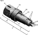
- FIG. 1 shows the side view of an adapter (1), which represents the first part of a two-part adapter according to the invention for introducing a dental implant into the bone.
- the adapter (1) has an elongated shape and comprises an apical part (3) and a head structure (10) at the coronal end of the adapter (1).
- At the apical part of the adapter there are formed three apically directed elongate snaps (5) having flares (6) directed outwardly from the axial direction, the three snaps (5) being arranged in a circular symmetry about the longitudinal axis of the adapter.
- apical anti-rotation means (9) are formed in the form of a series of alternately adjacent elevations and depressions.
- a position marking (11) of the anti-rotation means (9) in the form of a notch (11) is provided on the head structure (10).
- the diameter of the head structure (10) of the adapter (1) is increased compared to the apical part (3) of the adapter (1) and at the apical end of the head structure (10) there is a surface (12), which is opposite to the axial direction of the adapter angled at right angles.
- a circular recess (19) is formed, which runs parallel to the surface (12) at the apical end of the head structure (10) of the adapter (1) circularly around the head structure (10). Coronal of the circular recess, the head structure (10) is designed as a hexagonal screw head.
- FIG. 2 shows the side view of an adapter (1), which is the first part of a two-part adapter according to the invention for introducing a dental implant into the bone and is suitable for irreversible connection with a suitable second part of the two-part adapter according to the invention (counter-ring).
- the adapter (1) has an elongated shape and comprises an apical part (3) and a head structure (10) at the coronal end of the adapter (1).
- apical anti-rotation means (9) are formed in the form of a series of alternately adjacent elevations and depressions.
- a position marking (11) of the anti-rotation means (9) in the form of a notch (11) is provided on the head structure (10).
- the diameter of the head structure (10) of the adapter (1) is increased compared to the apical part (3) of the adapter (1) and at the apical end of the head structure (10) there is a surface (12), which is opposite to the axial direction of the adapter angled at right angles.
- a circular recess (19) is formed, which is parallel to the surface (12) at the apical end of the Head structure (10) of the adapter (1) extends circularly around the head structure (10).
- Coronal of the circular recess the head structure (10) is designed as a hexagonal screw head.
- the coronal, perpendicular to the axial direction of the adapter extending boundary of the rectangular recesses (20) is formed by the surface (12) at the apical end of the head structure (10) of the adapter (1).
- the rectangular depression (20) is delimited by a coronal surface (21) which is angled perpendicularly with respect to the axial direction of the adapter and a widening of the apical part (3) of the adapter (1) with respect to the rectangular depression (Fig. 20).
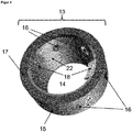
- FIG. 3 shows a counter-ring (13), which is the second part of a two-part adapter for introducing a dental implant into the bone, and a central recess (14), in an oblique plan view of the coronal surface (17) of the counter-ring (13) 13).
- fixing structures (16) in the form of six symmetrically distributed over the ring recesses (16) are formed as holes (16) in the outer wall (15) of the counter-ring (15). 13) are configured.
- On the coronal surface (17) of the counter-ring (13) are three anti-rotation means (24) in the form of three symmetrically over the coronal surface (17) of the counter-ring (13) distributed from the coronal surface (17) protruding projections (18) formed.
- FIG. 4 shows a counter-ring (13), which is the second part of a two-part adapter for introducing a dental implant into the bone, and a central recess (14), in an oblique plan view of the coronal surface (17) of the counter-ring (13) 13).
- fixing structures (16) in the form of six symmetrically distributed over the ring recesses (16) are formed as holes (16) in the outer wall (15) of the counter-ring (15). 13) are configured.
- On the inner surface (22) of the counter-ring (13) are coronal two opposing fins (18) present, which project obliquely apically into the central recess (14) of the counter-ring (13).
- FIG. 5 shows the side view of a two-part adapter for introducing a dental implant into the bone comprising the adapter (1) FIG. 1 and the counter-ring (13) FIG. 3 or the adapter (1) FIG. 2 and the counter-ring (13) FIG. 4 , wherein the apical part (3) of the adapter (1) in the central recess (14) of the counter-ring (13) is arranged.
- the outer diameter of the counter-ring (13) is approximately the same size as the outer diameter of the head structure (10) of the adapter (1).
- the counter-ring (13) is pushed as far as possible to the coronal over the apical part (3) of the adapter (1), so that the coronal surface (17) of the counter-ring (13), the apical surface (12) of the Head structure (10) of the adapter (1) touched.
- the apical part (3) of the adapter (1) protrudes apically out of the central recess (14) of the counter-ring (13), so that the apical anti-rotation means (9) and the three snap locks (5) with the outward broadening (6) are not obscured by the counter-ring (13).
- FIG. 6 shows the side view of an arrangement comprising the in FIG. 5 illustrated two-piece adapter for introducing a dental implant into the bone and an elongated dental implant (2), wherein the apical part (3) of the adapter (1) in the central recess (14) of the counter-ring (13) is arranged.
- the apical from the recess of the counter-ring (13) protruding part of the adapter (1) (shown in FIG. 5 ), which comprises the apically directed snap fasteners (5), is arranged in the coronal recess (4) of the dental implant (2).
- the outer diameter of the counter-ring (13), the head structure (10) and the dental implant (2) are approximately equal.
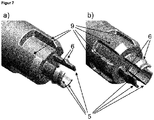
- FIG. 7 shows the apical end of the apical part (3) of an adapter (1), which is the first part of a two-part adapter according to the invention for introducing a dental implant into the bone.
- an adapter (1) which is the first part of a two-part adapter according to the invention for introducing a dental implant into the bone.
- the apical part (3) of the adapter (1) there are formed three apically directed elongated snaps (5) having flares (6) directed outward from the axial direction, the three snaps (5) being circularly symmetrical about the Longitudinal axis of the adapter are arranged.
- Apical anti-rotation means (9) in the form of each 3 alternately adjacent elevations and depressions are formed on the apical part (3) of the adapter (1) circular symmetrical about the apical end of the adapter (1 ) are arranged.
- FIG. 8 shows the apical end of the apical part (3) of an adapter (1), which is the first part of a two-part adapter according to the invention for introducing a dental implant into the bone.
- apical anti-rotation means (9) in the form of each 3 alternately adjacent elevations and depressions formed, which are arranged circular symmetrical about the apical end of the adapter (1).
- the apical ends of the three elevations of the anti-rotation means (9) are in this case designed as snap closures (5), the widenings (6) which are directed from the axial direction to the outside.
- the 3 elevations of the apical anti-rotation means (9) also each comprise a gap (23) which runs parallel to the longitudinal axis of the adapter through the apical end of the elevation, whereby the snaps are formed as springs, which can be elastically bent inwards.
- FIG. 8b are on the apical part (3) of the adapter (1) apical anti-rotation means (9) in the form of 6 alternately adjacent elevations and depressions formed, which are arranged circular symmetrical about the apical end of the adapter (1).
- the apical ends of 3 of the 6 elevations of the anti-rotation means (9) are in this case designed as snap closures (5), which have widenings (6) which are directed outward from the axial direction.
- the 3 protrusions which are formed as snap closures (5), each also comprise a gap (23) which extends parallel to the longitudinal axis of the adapter through the apical end of the survey, whereby the snaps are formed as springs, which bend elastically inwards. Hiss two surveys on which resilient snap closures (5) are formed, each is a survey without snap closure.
- FIG. 9 shows the apical end of the apical part (3) of an adapter (1), which is the first part of a two-part adapter according to the invention for introducing a dental implant into the bone.
- apical anti-rotation means (9) in the form of each 3 alternately adjacent elevations and depressions formed, which are arranged circular symmetrical about the apical end of the adapter (1).
- the apical ends of the three elevations of the anti-rotation means (9) are in this case designed as snap closures (5), the widenings (6) which are directed from the axial direction to the outside.
- apical anti-rotation means (9) in the form of 6 alternately adjacent elevations and depressions formed, which are arranged circular symmetrical about the apical end of the adapter (1).
- the apical ends of the 6 elevations of the anti-rotation means (9) are in this case designed as snap closures (5), the widenings (6), which are directed from the axial direction to the outside.
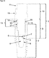
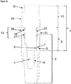
- FIG. 10 shows a longitudinal section of a side view of a two-part adapter according to the invention and a dental implant in the assembled state, wherein the first part is an adapter according to the Figures 2 and 7 and in the second part, a counter-ring according to FIG. 4 is.
- the outward from the axial direction widenings (6) of the snap closures (5) FIG. 7 are engaged in an undercut (7) on the inside (8) of the recess (4) of the dental implant (2).
- the undercut (7) is formed by an internal thread on the inside (8) of the recess (4) of the dental implant (2).
- coronal two opposing fins (18) are present, which protrude apically in the central recess (14) of the counter-ring (13).
- the fins (18) are arranged in the rectangular recesses (20) which are designed to be complementary to the fins (18) on the apical part (3) of the adapter (1).
- the coronally directed surfaces (21) defining the rectangular depressions (20) at their apical ends prevent the counter-ring (13) from sliding down apically beyond the level on which the fins (18) project with the coronal ones directed surfaces (21) come into contact.
- the fins (18) with the coronal surfaces (21) form an irreversible snap connection or plug connection between the adapter (1) and counter-ring (13).
- the fins (18) which are complementary in the rectangular recesses (20) are arranged on the apical part (3) of the adapter (1), a rotation of the counter-ring (13) about the longitudinal axis of the adapter (1) in assembled state prevented.
- the fins (18) and rectangular recesses (20) on the apical part (3) of the adapter (1) thus form complementary anti-rotation means.
- FIG. 11 shows a longitudinal section of a side view of a two-part adapter according to the invention and a dental implant in the assembled state, wherein the first part is an adapter according to FIG. 8 and in the second part, a counter-ring according to FIG. 4 is.
- the outward from the axial direction widenings (6) of the snap closures (5) FIG. 8 are engaged in an undercut (7) on the inside (8) of the recess (4) of the dental implant (2).
- the undercut (7) is located in the apical region of the anti-rotation means on the inside (8) of the recess (4) of the dental implant (2).
- the snap connection between the undercut (7) and the snap closures (5) can be easily separated and merged, as the snap fasteners (5) bend elastically inwards.
- the fins (18) are arranged in the rectangular recesses (20) which are designed to be complementary to the fins (18) on the apical part (3) of the adapter (1).
- the coronally directed surfaces (21) defining the rectangular depressions (20) at their apical ends prevent the counter-ring (13) from sliding down apically beyond the level on which the fins (18) project with the coronal ones directed surfaces (21) come into contact. Accordingly, the fins (18) with the coronal surfaces (21) form an irreversible snap connection between the adapter (1) and counter-ring (13).
- the fins (18) which are complementary in the rectangular recesses (20) are arranged on the apical part (3) of the adapter (1), a rotation of the counter-ring (13) about the longitudinal axis of the adapter (1) in assembled state prevented.
- the fins (18) and rectangular recesses (20) on the apical part (3) of the adapter (1) thus form complementary anti-rotation means.
- FIG. 12 shows a longitudinal section of a side view of a two-part adapter according to the invention and a dental implant in the assembled state, wherein the first part is an adapter according to FIG. 9 and in the second part, a counter-ring according to FIG. 4 is.
- the outward from the axial direction widenings (6) of the snap closures (5) FIG. 9 are engaged in an undercut (7) on the inside (8) of the recess (4) of the dental implant (2).
- the undercut (7) is located in the apical region of the anti-rotation means on the inside (8) of the recess (4) of the dental implant (2).
- coronal two opposing fins (18) are present, which protrude apically in the central recess (14) of the counter-ring (13).
- the fins (18) are arranged in the rectangular recesses (20) which are designed to be complementary to the fins (18) on the apical part (3) of the adapter (1).
- the coronally directed surfaces (21) defining the rectangular depressions (20) at their apical ends prevent the counter-ring (13) from sliding down apically beyond the level on which the fins (18) project with the coronal ones directed surfaces (21) come into contact. Accordingly, the fins (18) with the coronal surfaces (21) form an irreversible snap connection between the adapter (1) and counter-ring (13).
- the fins (18) which are complementary in the rectangular recesses (20) are arranged on the apical part (3) of the adapter (1), a rotation of the counter-ring (13) about the longitudinal axis of the adapter (1) in assembled state prevented.
- the fins (18) and rectangular recesses (20) on the apical part (3) of the adapter (1) thus form complementary anti-rotation means.
- FIG. 13 shows a longitudinal section of a side view of a two-part adapter according to the invention and a dental implant in the assembled state, wherein the first part is an adapter according to the FIGS. 1 and 7 and in the second part, a counter-ring according to FIG. 3 is.
- the widenings (6) of the snap fasteners (5) directed outward from the axial direction are latched into an undercut (7) on the inside (8) of the recess (4) of the dental implant (2).
- the undercut (7) is formed by an internal thread on the inside (8) of the recess (4) of the dental implant (2).
- the anti-rotation means (18) on the coronal surface of the counter-ring (24), consisting of projections (24) which project from the coronal surface (17) of the counter-ring (13) are in the complementary anti-rotation means (24) the apical surface (12) of the head structure (10) of the adapter (1), which are recesses (25) arranged.
Landscapes
- Health & Medical Sciences (AREA)
- Oral & Maxillofacial Surgery (AREA)
- Orthopedic Medicine & Surgery (AREA)
- Dentistry (AREA)
- Epidemiology (AREA)
- Life Sciences & Earth Sciences (AREA)
- Animal Behavior & Ethology (AREA)
- General Health & Medical Sciences (AREA)
- Public Health (AREA)
- Veterinary Medicine (AREA)
- Dental Prosthetics (AREA)
Abstract
Description
- Die vorliegende Erfindung beschreibt einen zweiteiligen Adapter zum Einbringen eines Dentalimplantats in den Knochen, wobei der erste Teil ein länglicher Adapter ist, an dessen apikalem Teil mindestens ein Schnappverschluss vorhanden ist, der bei Anordnung des apikalen Teils des Adapter in einer koronalen Ausnehmung des Dentalimplantats in mindestens eine komplementäre Struktur an der Innenseite der Ausnehmung des Dentalimplantats einrastet und eine reversible Steckverbindung zwischen Adapter und Dentalimplantat herstellt, und der zweite Teil ein Konter-Ring ist, in dessen zentraler Ausnehmung der apikale Teil des Adapters angeordnet ist.
- Für den Ersatz menschlicher Zähne existieren unterschiedliche Zahnersatzlösungen. Bei einem Implantatsystem wird ein Zahnimplantat in den menschlichen Kieferknochen eingesetzt und dient als künstliche Zahnwurzel der Befestigung von prothetischen Komponenten wie z.B. einem Aufbauteil oder Abutment. Die Verwendung von Dentalimplantaten als künstlichen Ersatz für Zahnwurzeln hat sich in den letzten Jahren etabliert. Es gibt verschiedene Formen von Dentalimplantaten, wobei sich insbesondere die schraubenförmigen Implantate bewährt haben.
- Schraubenförmige Dentalimplantate bestehen üblicherweise aus einem Verankerungsteil zur Verankerung des Implantats im Knochen und einem Aufbauteil, auf dem eine Suprakonstruktion, beispielsweise eine Krone, befestigt werden kann. Wenn Verankerungsteil und Aufbauteil als ein einziges Bauteil ausgebildet sind, spricht man von einem einteiligen Implantat. Meistens werden zweiteilige Implantate verwendet, bei denen Verankerungsteil und Aufbauteil als zwei separate Bauteile ausgebildet sind.
- Zum Fixieren eines schraubenförmigen Dentalimplantats im Knochen wird das Implantat in ein passendes Bohrloch mit vorbereiteter Innengewindebohrung eingedreht oder es besitzt ein selbstschneidendes Außengewinde, das beim Eindrehen in ein präpariertes Sackloch ein Innengewinde selbst erzeugt. Zylinderimplantate hingegen haben an ihrer Außenseite kein Gewinde und werden in ein im Knochen vorbereitetes Sackloch eingedrückt. Die Entnahme des Implantats aus seinem Aufnahmebehälter und das Einsetzen müssen unter sterilen Bedingungen erfolgen.
- Um das Eindrehen eines Dentalimplantats in den Knochen zu ermöglichen, weisen konventionelle Implantate im Bereich des Verankerungsteils und/oder des Aufbauteils üblicherweise eine zentrale Ausnehmung auf, an deren Innenwand ein Innengewinde vorhanden ist. Dieses kann zur Befestigung eines verschraubbaren Adapters genutzt werden, an dem ein Einbringinstrument, beispielsweise ein Eindrehwerkzeug, zum Übertragen eines Torsionsmoments auf das Implantat befestigt werden kann. Solche verschraubbaren Adapter sind beispielsweise aus
EP 1 038 506 bekannt. - Üblicherweise sind Implantate bereits in ihrer sterilen Verpackung mit einem solchen Adapter verbunden, so dass das Implantat mittels des Adapters aus der Verpackung entnommen werden kann. Hierzu kann der Adapter bereits bei der Entnahme aus der Verpackung mit einem geeigneten Einbringwerkzeug verbunden werden und so auf das Bohrloch bzw. Sackloch, also die Stelle, an der es in den Knochen eingesetzt werden soll, aufgesetzt und eingebracht werden.
- Zum Einbringen wird auf den am Implantat verankerten Adapter ein Torsionsmoment mittels eines Einbringwerkzeugs ausgeübt, wie beispielsweise einer Ratsche. Anschließend wird der Adapter wieder vom Dentalimplantat gelöst, indem die zentrale Schraube, die zur Fixierung des Adapters am Implantat dient, herausgedreht bzw. geschraubt wird.
- Das Lösen dieser im Innengewinde des Implantats fixierten Adapterschraube ist zeitaufwändig und es besteht die Gefahr, dass es während dieses Vorgangs des Herausdrehens zu Verunreinigungen des Implantats kommt, die eine mikrobielle Besiedlung des Implantats begünstigen, wenn die Handhabung nicht sehr sorgfältig erfolgt. Zudem besteht die Gefahr, dass durch die Manipulation beim Herausdrehen der Adapterschraube die Position des Implantats im Knochen unvorteilhaft verändert wird. Diese Gefahr ist besonders dann gegeben, wenn das Implantat nach dem Einbringen in den Knochen nicht fest fixiert ist.
- Da bei bekannten Adaptern oft ein zentraler Schraubenkanal vorhanden ist, der für die Fixierung des Adapters am Implantat über die zentrale Adapterschraube notwendig ist, kommt es aufgrund dieser Bauteilgeometrie zu einer Schwächung des Adapters, so dass dieser bei höheren Drehmomenten aufgrund eines sehr harten Knochens versagen kann (z.B. Bruch). Diese Bruchgefahr ist umso mehr gegeben, wenn der Adapter aus Kunststoff hergestellt wurde.
- Nach Einbringung des Implantats mit Hilfe eines verschraubten Adapters ist zudem oft ein erhöhter Kraftaufwand notwendig, um die zentrale Adapterschraube zu lösen, um den Adapter zu entfernen. Dabei besteht eine erhöhte Bruchgefahr der Adapterschraube. Wenn es zum Schraubenbruch kommt, gestaltet sich das Entfernen eines Schraubenfragmentes aus dem Innengewinde sehr zeitaufwendig und es besteht ein hohes Risiko, dass das Implantat in der zentralen Ausnehmung beschädigt bzw. zerkratzt wird.
- Zudem besteht die Gefahr, dass beim Einbringen des Implantates mit Hilfe eines verschraubten Adapters die zentrale Fixationsschraube bricht, wenn durch unsachgemäßes Manipulieren der Adapter im Verhältnis zum Implantat eine seitliche Belastung erfährt.
- Ein weiterer Nachteil beim Lösen der zentralen Adapterschraube besteht darin, dass oftmals kein Platz zwischen Ober- und Unterkiefer für den Schraubendreher vorhanden ist, um die Adapterschraube zu lösen. Dies betrifft in besonderem Maße die hinteren Bereiche der Mundhöhle. Es kommt hinzu, dass die komplizierten und zeitaufwendigen Drehbewegungen, die mit den Fingern auf den Schraubendreher übertragen werden müssen, ausschließen, dass man diesen stets in sicherem Griff hat. Dadurch steigt die Gefahr, dass dieser abrutschen und vom Patienten in die Lunge aspiriert werden kann. Dies gilt in gleichem Maße für den Adapter bzw. die Adapterschraube, wenn diese Bauteile keine sichere Steckverbindung mit dem Schraubendreher eingehen.
- Aufgabe der Erfindung ist es daher, einen gegenüber dem Stand der Technik verbesserten Adapter zum sterilen Herausnehmen eines Implantats aus der Verpackung und anschließenden Einbringen des Implantats in den Knochen bereitzustellen. Der erfindungsgemäße Adapter sollte eine schnelle, einfache und sichere Handhabung bei der Trennung von Implantat und Adapter nach Einsetzen des Implantats in den Knochen ermöglichen. Die Trennung des Adapters vom Implantat sollte möglichst keine oder zumindest nur eine geringe mechanische Belastung auf das eingesetzte Implantat und den Knochen verursachen. Besonders zu vermeiden ist dabei das Einwirken von Kräften, die nicht in der Axialrichtung des Dentalimplantats wirken.
- Die oben beschriebene technische Aufgabe wird erfindungsgemäß gelöst durch die Bereitstellung einer zweiteiligen Vorrichtung zum Einbringen eines Dentalimplantats in einen Knochen, wobei
- ein erster Teil ein länglicher Adapter ist, an dessen apikalem Teil mindestens ein Schnappverschluss vorhanden ist, der bei Anordnung des apikalen Teils des Adapter in einer koronalen Ausnehmung des Dentalimplantats in eine komplementäre Struktur an der Innenseite der Ausnehmung des Dentalimplantats einrastet und eine reversible Steckverbindung zwischen Adapter und Dentalimplantat herstellt, und
- ein zweiter Teil ein Konter-Ring ist, in dessen zentraler Ausnehmung der apikale Teil des Adapters angeordnet ist.
- Im Sinne der vorliegenden Erfindung kann die erfindungsgemäße zweiteilige Vorrichtung auch als zweiteiliger Adapter bezeichnet werden. Die vorliegende Erfindung umfasst entsprechend als ersten Teil des erfindungsgemäßen zweiteiligen Adapters einen Adapter, der mit einem Dentalimplantat über einen Schnappverschluss verbunden werden kann. Der Anwender kann das Implantat mit Hilfe eines Einbringinstrumentes, das eine Steckverbindung mit dem Adapter eingeht, sicher steril aus der Verpackung nehmen und in den Knochen einbringen, ohne das Implantat direkt zu berühren.
- Die Steckverbindung bzw. Schnappverbindung zwischen Adapter und Implantat wird durch mindestens einen Schnappverschluss hergestellt, der am apikalen Teil des Adapters ausgebildet ist. Der Schnappverschluss kann hierbei in allen Bereichen des apikalen Teils des Adapters ausgebildet sein. Beispielsweise kann der Schnappverschluss als ein in Längsrichtung des Adapters nach apikal gerichteter Fortsatz ausgebildet sein, der vom apikalen Ende des Adapters entspringt. Ein solcher Fortsatz, aber auch ein Schnappverschluss, der in anderen Bereichen des apikalen Teils des Adapters ausgebildet ist, kann elastisch bzw. federnd ausgebildet sein, so dass er sich beispielsweise nach innen, also zur Mittelachse des Adapters hin verbiegen lässt, wenn von außen eine Kraft auf den Schnappverschluss ausgeübt wird. In anderen Ausführungsformen ist der Schnappverschluss nicht als federnde Struktur am apikalen Teil des Adapters ausgestaltet, sondern umfasst lediglich eine Struktur im apikalen Teil des Adapters, wie beispielsweise eine Verbreiterung oder eine Vertiefung, die in eine komplementäre Struktur an der Innenseite der koronalen Ausnehmung des Dentalimplantats einrastet. Die notwendige Verformung des Schnappverschlusses bzw. der komplementären Strukturen an der Innenseite der koronalen Ausnehmung des Dentalimplantats, die beim Einführen des apikalen Teils des Adapters in die koronale Ausnehmung des Dentalimplantats vor dem Einrasten des Schnappverschlusses erfolgt, kann hierbei beispielsweise durch elastische Eigenverformung des Materials des Adapters und/oder des Dentalimplantats ermöglicht werden. In bevorzugten Ausführungsformen der Erfindung sind zwei, drei oder mehr Schnappverschlüsse ausgebildet. In Ausführungsformen des Adapters mit mehreren Schnappverschlüssen können die Schnappverschlüsse zirkulär symmetrisch um die Längsachse des Adapters angeordnet sein.
- Ein erfindungsgemäßer zweiteiliger Adapter, der mit einem Implantat verbunden ist, lässt sich nach dem Einbringen des Implantats in den Knochen durch das Wirken einer nach koronal gerichteten Zugkraft von dem Implantat trennen. Das Einwirken der Zugkraft auf den Adapter führt zu einer Verformung des Schnappverschlusses und/oder der komplementären Strukturen an der Innenseite der koronalen Ausnehmung des Dentalimplantats, beispielsweise durch Zurückfedern des Schnappverschlusses oder elastische Eigenverformung des Materials des Adapters, wenn der Schnappverschluss am Unterschnitt an der Innenseite des Implantats vorbeigezogen wird.
- Es ist besonders vorteilhaft, dass sich die Trennung durch eine einzelne Bewegung ausführen lässt und sehr schnell nach Einwirken der Zugkraft erfolgt, wobei der Anwender die Teile stets sicher im Griff hat. Ein weiterer Vorteil des erfindungsgemäßen Adapters ist, dass Krafteinwirkungen in Richtungen, die von der Axial- bzw. Längsrichtung des Adapters abweichen, während des Lösens der Wirkverbindung zwischen Adapter und Implantat bei sachgerechter Handhabung nicht auftreten. Dies gewährleistet bevorzugt eine geringe mechanische Belastung des Knochens und des Implantats während des Trennvorgangs und ermöglicht, dass das Implantat seine Position während des Trennvorgangs im Wesentlichen nicht verändert.
- Bisher wurde die Verbindung zwischen einem Adapter und einem Implantat mit Innengewinde durch das Einschrauben der Adapterschraube in das Innengewinde des Dentalimplantats hergestellt. Diese Art der Verbindung geht aber mit den beschriebenen Nachteilen beim Lösen der Verbindung einher. Diese Nachteile wurden bisher nicht überwunden, obwohl die Problematik lange bekannt war, da die Notwendigkeit der Herstellung einer Schraubverdingung aufgrund des vorhandenen Innengewindes als gegeben angesehen wurde. Zudem ging man davon aus, dass nur eine Schraubverbindung für die erforderliche Stabilität sorgen kann. Der erfindungsgemäße Adapter stellt daher eine überraschende und vorteilhafte Lösung des Problems dar, einen Adapter bereitzustellen, der eine schnelle, einfache und sichere Handhabung bei der Trennung von Implantat und Adapter nach Einsetzen des Implantats in den Knochen ermöglicht und trotzdem stabil mit dem Implantat verbunden ist.
- Ein Vorteil des erfindungsgemäßen zweiteiligen Adapters ist, dass der Konter-Ring, der den zweiten Teil des erfindungsgemäßen Adapters darstellt, nach Einbringen des Implantats in den Knochen mit Hilfe des erfindungsgemäßen zweiteiligen Adapters zur Fixierung des Implantats in seiner Position im Knochen genutzt werden kann, während der erste Teil des Adapters mittels einer nach koronal wirkenden Zugkraft vom Implantat getrennt werden kann. Hierbei wird der Konter-Ring nach dem Einbringen des Implantats in den Knochen auf dem koronalen Ende des Implantats (der Implantat-Schulter) durch eine am Konter-Ring angreifende Kraft fixiert, während der erste Teil des erfindungsgemäßen zweiteiligen Adapters durch eine nach koronal wirkende Kraft aus der koronalen Ausnehmung des Implantats herausgezogen wird. Durch die Fixierung des Konter-Rings auf der Implantat-Schulter verändert das Implantat bei diesem Vorgang seine Position nicht. Durch den Einsatz des Konter-Ring wird somit die Gefahr der Positionsveränderung des Implantats überraschend minimiert. Weiterhin wird die mechanische Belastung für den Knochen und das Implantat minimiert. Mithilfe des erfindungsgemäßen zweiteiligen Adapters ist es sogar möglich, den ersten Teil des Adapters von einem in den Knochen eingebrachten Implantat zu lösen, wenn das Implantat nicht fest im Knochen verankert ist.
- Ein weiterer Vorteil des Konter-Rings ist, dass er es ermöglicht, das Implantat im Knochen zu fixieren, ohne dass zusätzliche Instrumente direkt am Implantat ansetzen müssen, um dieses während der Trennung vom ersten Teil des erfindungsgemäßen Adapters im Knochen zu fixieren, wie dies bei bekannten Adapter-Implantat-Lösungen der Fall ist. Durch das Ansetzen von Fixierungsinstrumenten am Implantat können Beschädigungen auftreten, die das Implantat brüchig machen und somit seine Haltbarkeit und Stabilität unter Belastung negativ beeinflussen. Zudem können solche Beschädigungen, die oft in Form von Kratzern oder Rissen in der Implantat-Oberfläche auftreten, die Ansiedlung von Bakterien und anderen Mikroorganismen am Implantat fördern, was sich negativ auf die Funktion des Implantats, aber auch auf die Funktion und Gesundheit der angrenzenden Strukturen im Mundraum, wie beispielsweise die benachbarten Zähne, das angrenzende Zahnfleisch und den angrenzenden Knochen, auswirkt. Zudem stellen Infektionen und Besiedelungen mit Mikroorganismen eine Gefahr für die allgemeine Gesundheit dar, da es beispielsweise im Falle einer Immunsuppression zu einer systemischen Ausbreitung der Infektion kommen kann.
- Zusätzlich verleiht die Verwendung des Konter-Rings, der zur Fixierung des Implantats in seiner Position im Knochen während der Trennung der Verbindung von Adapter und Implantat genutzt wird, dem Anwender mehr Sicherheit bei seiner Arbeit, da er eine mögliche Positionsänderung des Implantats durch den Trennungsvorgang mit Hilfe des Konter-Rings verhindern kann. Dies ermöglicht gleichzeitig eine schnellere Arbeitsweise, da vor der Trennung der Verbindung von Adapter und Implantat nicht überprüft werden muss, ob die Verankerung des Implantats im Knochen der Krafteinwirkung des Trennvorgangs standhalten würde. Hierdurch wird die Anzahl der Arbeitsschritte zum Einbringen des Implantats in den Knochen verringert, was das Risiko der Verunreinigung und der mikrobiellen Besiedlung des Implantats minimiert. Es war überraschend, dass die genannten Vorteile durch die Hinzunahme eines Konter-Rings in die Anordnung von Implantat und Adapter erzielt werden konnten.
- In einer bevorzugten Ausführungsform des erfindungsgemäßen zweiteiligen Adapters umfasst der Schnappverschluss am apikalen Teil des Adapters, der den ersten Teil des erfindungsgemäßen zweiteiligen Adapters darstellt, eine von einer Axialrichtung des Adapters nach außen gerichtete Verbreiterung, wobei die Verbreiterung bei Anordnung des apikalen Teils des Adapter in der koronalen Ausnehmung des Dentalimplantats in einen Unterschnitt an der Innenseite der Ausnehmung des Dentalimplantats einrastet. Der Schnappverschluss ist bevorzugt so ausgebildet, dass er eine Verbreiterung aufweist, die nach außen, also senkrecht zur Axialrichtung des Adapters von der Mittelachse weg gerichtet ist. Wenn der Adapter in dieser bevorzugten Ausführungsform mit seinem apikalen Teil in die koronale Ausnehmung des Dentalimplantats eingeführt wird, kommt die Verbreiterung des Schnappverschlusses mit einem Unterschnitt an der Innenwand des Dentalimplantats in Kontakt, der die koronale Ausnehmung verengt. Bei Fortführung der Einführbewegung des Adapters in die Ausnehmung des Implantats wird der Schnappverschluss daher nach innen gebogen, solange, bis die Verbreiterung des Schnappverschlusses am Unterschnitt des Implantats vorbeigeschoben wurde. In diesem Moment verschiebt sich der Schnappverschluss zurück in seine Ausgangsposition und ist in den Unterschnitt an der Innenseite der Ausnehmung des Dentalimplantats eingerastet und hierdurch mit dem Implantat verbunden.
- Ein überraschender Vorteil dieser bevorzugten Ausführungsform des Adapters, der den ersten Teil des erfindungsgemäßen zweiteiligen Adapters darstellt, ist, dass er mit praktisch allen existierenden Dentalimplantaten kompatibel ist, die eine koronale Ausnehmung aufweisen, an deren Innenseite ein Innengewinde vorhanden ist, das eigentlich für die Befestigung von prothetischen Komponenten vorgesehen ist. Dabei kann die Verengung der koronalen Ausnehmung, die den für das Einrasten der nach außen gerichteten Verbreiterung des Schnappverschlusses notwendigen Unterschnitt bildet, durch das Innengewindes an der Innenseite der Ausnehmung des Dentalimplantats gebildet werden. Alternativ kann auch jeder andere Unterschnitt, der sich an der Innenwand der zentralen Ausnehmung des Dentalimplantats befindet, für die Herstellung der Wirkverbindung zwischen Adapter und Implantat mittels des Schnappverschlusses genutzt werden.
- In einer anderen bevorzugten Ausführungsform des erfindungsgemäße zweiteilige Adapter umfasst der Schnappverschluss am apikalen Teil des Adapters, der den ersten Teil des erfindungsgemäßen zweiteiligen Adapters darstellt, eine nach innen gerichtete Vertiefung, wobei die Vertiefung bei Anordnung des apikalen Teils des Adapter in der koronalen Ausnehmung des Dentalimplantats in einen Unterschnitt an der Innenseite der Ausnehmung des Dentalimplantats einrastet. Der Unterschnitt bzw. die Verbreiterung an der Innenseite der Ausnehmung des Dentalimplantats ragt nach innen in die zentrale Ausnehmung des Dentalimplantats. Der Schnappverschluss ist bevorzugt so ausgebildet, dass er eine Vertiefung aufweist, die nach innen, also senkrecht zur Axialrichtung des Adapters zur Mittelachse hin gerichtet ist. Wenn der Adapter in dieser bevorzugten Ausführungsform mit seinem apikalen Teil in die koronale Ausnehmung des Dentalimplantats eingeführt wird, kommt der Schnappverschluss mit dem Unterschnitt an der Innenwand des Dentalimplantats in Kontakt, der die koronale Ausnehmung verengt. Bei Fortführung der Einführbewegung des Adapters in die Ausnehmung des Implantats wird der Schnappverschluss daher nach innen gebogen, solange, bis die Vertiefung des Schnappverschlusses in den Bereich des Unterschnitts an der Innenwand des Implantats gelangt. In diesem Moment verschiebt sich der Schnappverschluss zurück in seine Ausgangsposition und der Unterschnitt an der Innenseite der Ausnehmung des Dentalimplantats ist in die Vertiefung eingerastet und hierdurch mit dem Implantat verbunden.
- Ein überraschender Vorteil dieser bevorzugten Ausführungsform des Adapters, der den ersten Teil des erfindungsgemäßen zweiteiligen Adapters darstellt, ist, dass er mit praktisch allen existierenden Dentalimplantaten kompatibel ist, die eine koronale Ausnehmung aufweisen, an deren Innenseite ein Innengewinde vorhanden ist, das eigentlich für die Befestigung von prothetischen Komponenten vorgesehen ist. Dabei kann die Verengung der koronalen Ausnehmung, die den für das Einrasten der nach innen gerichtete Vertiefung des Schnappverschlusses notwendigen Unterschnitt bildet, durch das Innengewindes an der Innenseite der Ausnehmung des Dentalimplantats gebildet werden. Alternativ kann auch jeder andere Unterschnitt, der sich an der Innenwand der zentralen Ausnehmung des Dentalimplantats befindet, für die Herstellung der Wirkverbindung zwischen Adapter und Implantat mittels des Schnappverschlusses genutzt werden.
- In einer bevorzugten Ausführungsform des erfindungsgemäßen zweiteiligen Adapters umfasst der Adapter, der den ersten Teil des erfindungsgemäßen zweiteiligen Adapters darstellt, apikale Drehsicherungsmittel. Entsprechend komplementäre Drehsicherungsmittel sind an einem koronalen Ende des mit dem Adapter verbundenen oder zu verbindenden Dentalimplantats ausgebildet. Die Drehsicherungsmittel verhindern, dass es im verbundenen Zustand zu Rotationsbewegungen zwischen dem Adapter und dem Implantat kommen kann. Dies ist insbesondere beim Einbringen des Implantats von großer Bedeutung, da hierbei Torsionskräfte auf den Adapter und das Implantat wirken, die von einem am koronalen Ende des Adapters ansetzenden Einbringwerkzeug (beispielsweise einer implantologischen Ratsche) ausgeübt werden.
- Es ist überraschend, dass eine Schnappverbindung zwischen Adapter und Implantat gegen Rotationsbewegungen um die Längsachse gesichert werden kann. Dies bietet gegenüber einem in das Innengewinde des Implantats eingeschraubten Adapter den Vorteil, dass die Verbindung zwischen Adapter und Implantat gegen Rotationsbewegungen in beide Drehrichtungen um die Längsachse gesichert ist. Somit wird eine starre Verbindung zwischen Adapter und Implantat beim Einwirken von Torsionskräften in beide Drehrichtungen sichergestellt.
- In einer weiteren bevorzugten Ausführungsform des erfindungsgemäßen zweiteiligen Adapters umfasst ein koronales Ende des Adapters, der den ersten Teil des erfindungsgemäßen zweiteiligen Adapters darstellt, eine Kopfstruktur. Die Kopfstruktur stellt eine Struktur dar, die sich in ihrer Form vom apikalen Teil des Adapters absetzt. Sie dient der Aufnahme eines geeigneten Einbringinstruments, das zu der Kopfstruktur komplementäre Strukturen aufweist, wodurch eine starre Wirkverbindung zwischen dem Adapter und dem Einbringinstrument hergestellt werden kann. Die Kopfstruktur kann in verschiedener Art und Weise ausgestaltet sein und kann an die funktionellen Erfordernisse des zu verwendenden Einbringinstrumentes angepasst werden.
- Ein großer Vorteil dieser Ausführungsform der Erfindung ist, dass der erfindungsgemäße erste Teil des zweiteiligen Adapters mit einer Kopfstruktur ausgestattet werden kann, die für den Verankerungsmechanismus des jeweils verbundenen Implantats besonders vorteilhaft ist. Somit kann der erfindungsgemäße Adapter für das Einbringen verschiedener Implantat-Typen genutzt werden, die unterschiedliche Einbringmechanismen haben, wie z.B. Schraubenimplantate, Zylinderimplantate ohne Gewinde oder Stufenzylinderimplantate.
- Überraschenderweise ermöglicht die Kopfstruktur zudem die sterile Entnahme des mit dem Adapter verbundenen Implantats aus der Verpackung. Dies kann beispielsweise per Hand geschehen, wenn die Kopfstruktur so ausgebildet ist, dass sie mit den Fingern gegriffen und im Anschluss mit einem Einbringwerkzeug verbunden werden kann, ohne dass das Implantat berührt wird. In einem anderen Beispiel kann die Entnahme des mit dem Implantat verbundenen Adapters direkt mit Hilfe des Einbringwerkzeugs erfolgen, indem die Verbindung zwischen der Kopfstruktur und dem Einbringinstrument bereits vor der Entnahme des mit dem Adapter verbundenen Implantats hergestellt wird. Die Verbindung zwischen dem Einbringinstrument und der Kopfstruktur wird bevorzugt in Form einer Steckverbindung hergestellt.
- In einer bevorzugten Ausführungsform des erfindungsgemäßen zweiteiligen Adapters weist die Kopfstruktur eine Positionsmarkierung der Drehsicherungsmittel auf. Die Positionsmarkierung zeigt die Orientierung der Drehsicherungsmittel des Adapters an, wodurch auf die Orientierung der Drehsicherungsmittel des Implantats geschlossen werden kann, da diese komplementär zu den Drehsicherungsmitteln des Adapters ausrichtet sind. Als Positionsmarkierung kann ein definiertes Strukturelement in der Kopfstruktur dienen, dessen Position im Verhältnis zu den Drehsicherungsmitteln bekannt ist. Auch ist es möglich, dass die Kopfstruktur als Ganzes als Positionsmarkierung der Drehsicherungsmittel fungiert, wenn sie Elemente aufweist, deren Position im Verhältnis zu den apikalen Drehsicherungsmitteln bekannt ist. Auch oberflächliche Markierungen, die keine strukturellen Merkmale der Kopfstruktur darstellen, wie beispielsweise spezifisch angebrachte Aufkleber oder Farbmarkierungen, können als Positionsmarkierungen der Drehsicherungsmittel fungieren.
- Ein überraschender Vorteil dieser Ausführungsform der vorliegenden Erfindung ist, dass mit Hilfe der Positionsmarkierungen während des Einbringens des Implantats in den Knochen und vor Trennung des Adapters vom Implantat die Orientierung der Drehsicherungsmittel des Implantats bestimmt werden kann. Dies geschieht durch Überprüfung der Orientierung der Positionsmarkierung der Drehsicherungsmittel an der Kopfstruktur, beispielsweise mittels eines Intraoralscanners. Die Information über die Orientierung der Drehsicherungsmittel des Implantats ist wichtig für den nachfolgenden Aufbau der koronalen prothetischen Komponenten auf dem Implantat, da auch diese über Drehsicherungsmittel verfügen, die komplementär zu denen des Implantats sind. Entsprechend beeinflusst die Orientierung und Positionierung der Drehsicherungsmittel des Implantats die spätere Position der prothetischen Komponenten.
- Bei einer nicht optimalen Positionierung der Drehsicherungsmittel des Implantats kann eine Veränderung der Position durch erneutes Ansetzen des Einbringinstruments am Adapter korrigiert werden, ohne dass die Verbindung zwischen Adapter und Implantat getrennt werden muss. Dies verringert die Anzahl der notwendigen Arbeitsschritte, um das Implantat in die vorgesehene Position zu bringen, wodurch die Gefahr von Verunreinigungen des Implantats während des Einbringprozesses verringert wird. Zudem werden die mechanischen Belastungen für Implantat und Knochen gering gehalten. Ein weiterer entscheidender Vorteil ist die überraschend große Zeitersparnis, die durch die Verringerung der Arbeitsschritte erzielt wird.
- In einer weiteren bevorzugten Ausführungsform des erfindungsgemäßen zweiteiligen Adapters handelt es sich bei der Positionsmarkierung an der Kopfstruktur um eine Kerbe. Die Kerbe kann beispielsweise senkrecht zur Axialrichtung der Schraube über die koronale Fläche der Kopfstruktur verlaufen. Da die Orientierung der Kerbe im Verhältnis zu den Drehsicherungsmitteln des Adapters bekannt ist, kann aus der Information über die Orientierung der Kerbe auf die Position der Drehsicherungsmittel des Adapters und des Implantats geschlossen werden. Es ist vorteilhaft, dass es durch eine so einfache Markierung möglich ist, auf die Position der Drehsicherungsmittel des Implantats zu schließen, was zu einem sichereren und effizienteren Einbringprozess des Implantats in den Knochen beiträgt.
- Überraschenderweise kann die Kerbe neben ihrer Funktion als Positionsmarkierung für die Drehsicherungsmittel des Adapters auch als Ansatzpunkt für ein Einbringinstrument dienen, das einen Fortsatz hat, der komplementär in die Kerbe greift, wodurch die Übertragung einer Torsionskraft vom Einbringinstrument auf Adapter und Implantat ermöglicht wird.
- In einer weiteren bevorzugten Ausführungsform des erfindungsgemäßen zweiteiligen Adapters hat die Kopfstruktur im Vergleich zum apikalen Teil des Adapters einen vergrößerten Durchmesser und am apikalen Ende der Kopfstruktur befindet sich eine Fläche, die gegenüber der Axialrichtung des Adapters abgewinkelt ist. Der gegenüber dem apikalen Teil vergrößerte Durchmesser der Kopfstruktur ermöglicht eine einfachere Handhabung des Adapters, beispielsweise wenn er manuell an der Kopfstruktur angefasst wird.
- Ein überraschender Vorteil des vergrößerten Durchmessers der Kopfstruktur ist, dass hierdurch der Schwerpunkt der Verbindung aus Implantat und Adapter nach koronal verschoben wird, wodurch die Handhabung des Implantats nach Herstellung der Verbindung zwischen Einbringinstrument und Adapter erleichtert wird und damit auch der Vorgang des Einbringens des Implantats in den Knochen.
- In einer weiteren bevorzugten Ausführungsform des erfindungsgemäßen zweiteiligen Adapters umfasst die Kopfstruktur eine parallel zur Fläche am apikalen Ende der Kopfstruktur des Adapters zirkulär um die Kopfstruktur verlaufende Vertiefung. Hierbei handelt es sich um eine Kerbe, die über die Seitenfläche der Kopfstruktur des Adapters verläuft, wobei die Ebene des Kerben-Verlaufs senkrecht zur Axialrichtung des Adapters ausgerichtet ist. Die um die Kopfstruktur verlaufende Vertiefung oder Kerbe kann zur Herstellung einer Steckverbindung zwischen der Kopfstruktur und einem geeigneten Einbringinstrument genutzt werden kann. Zudem kann die Kerbe dazu dienen, den Adapter, wenn dieser zusammen mit dem einzubringenden Dentalimplantat im verbundenen Zustand in der Verpackung vorliegt, in der Verpackung zu fixieren, indem eine klammer- oder manschettenartige Struktur, die Teil der Verpackung ist, von der Innenseite der Verpackung in die Kerbe greift. Somit kann der erfindungsgemäße zweiteilige Adapter zusammen mit dem verbundenen Dentalimplantat innerhalb der Verpackung fixiert werden, so dass die Implantatoberfläche nicht mit der Verpackung in Berührung kommt. Hierdurch ist sichergestellt, dass es nicht durch Verunreinigungen der Verpackung zu Kontaminationen des einzubringenden Dentalimplantats kommt, wodurch das Risiko von Infektionen minimiert werden kann.
- In einer weiteren bevorzugten Ausführungsform des erfindungsgemäßen zweiteiligen Adapters sind die Außendurchmesser des Konter-Rings, der Kopfstruktur und des Dentalimplantats in etwa gleich groß. Hierdurch ist gewährleistet, dass der Konter-Ring im zusammengesetzten Zustand von zweiteiligem Adapter und Implantat zwischen der Kopfstruktur des ersten Teils des Adapters und dem Implantat angeordnet ist und aus dieser Position nur durch Trennung der Wirkverbindung zwischen dem Implantat und dem ersten Teil des Adapters herausbewegt werden kann. Der Konter-Ring ist also zwischen dem koronalen Ende des Implantats und dem apikalen Ende der Kopfstruktur des ersten Teils des Adapters eingeschlossen. Wird der Konter-Ring nach Einbringen des Implantats mit Hilfe des erfindungsgemäßen zweiteiligen Adapters in den Knochen nach apikal geschoben, so kommt er in Kontakt mit dem koronalen Ende des Implantats, also der Implantatschulter, und kann nicht weiter nach apikal geschoben werden. Weiterhin wird hierdurch verhindert, dass der Konter-Ring im zusammengesetzten Zustand von erfindungsgemäßem zweiteiligem Adapter und Implantat über die Kopfstruktur am koronalen Ende des ersten Teils des Adapters nach koronal bewegt wird und aus der Anordnung entfernt wird. Die Formulierung "in etwa gleich groß" ist in diesem Zusammenhang so zu verstehen, dass leichte Abweichungen der Außendurchmesser von Implantat, Konter-Ring und Kopfstruktur des Adapters möglich sind, wobei der Außendurchmesser des Implantats immer mindestens genauso groß oder größer ist als die Außendurchmesser des Konter-Rings und der Kopfstruktur. Hierdurch ist sichergestellt, dass das Implantat auch tiefer als Knochenniveau in den Knochen eingebracht werden kann. Zudem wird eine Kollision mit benachbarten Zähnen vermieden. Im Rahmen der vorliegenden Erfindungen sind leichte Abweichungen bzw. Verringerungen des Außendurchmessers der Kopfstruktur oder des Konter-Rings gegenüber dem Außendurchmesser des Implantats tolerierbar im Bereich von 2 mm, bevorzugt 1 mm, besonders bevorzug 0,5 mm, ganz besonders bevorzug 0,1 mm, solange die hier dargestellten Merkmale der bevorzugten Ausführungsform der Erfindung realisiert werden.
- Dadurch, dass der Konter-Ring in etwa den gleichen Außendurchmesser wie das Implantat und die Kopfstruktur des Adapters hat, ist es möglich, dass im zusammengesetzten Zustand von Adapter, Konter-Ring und Implantat, zusätzlich zum ggf. aufgebrachten Drehmoment, eine nach apikal auf den Ring ausgeübte Kraft auf das koronale Ende des Implantats übertragen wird, wodurch dieses in seine endgültige Position im Knochen gebracht wird.
- In einer weiteren bevorzugten Ausführungsform des zweiteiligen Adapters weist die Außenseite des Konter-Rings Fixierungsstrukturen auf. Die Fixierungsstrukturen ermöglichen es dem Anwender, die Position des Konter-Rings zu kontrollieren und diesen in eine gewünschte Position zu bringen und dort zu fixieren. Die Fixierungsstrukturen bilden Angriffspunkte für beispielsweise ein Instrument oder die manuelle Handhabung durch den Anwender, ohne hierauf limitiert zu sein. Dem Fachmann sind geeignete Fixierungsstrukturen bekannt und mögliche Formen der Ausgestaltung der Fixierungsstrukturen ergeben sich für den Fachmann aus der detaillierten Beschreibung. Dies gilt ebenfalls für geeignete Instrumente, die an den Fixierungsstrukturen angreifen.
- Nach Einbringen des Implantats in den Knochen mit Hilfe des verbundenen zweiteiligen Adapters kann der Konter-Ring durch Ansetzten einer nach apikal gerichteten Kraft an den Fixierungsstrukturen auf das koronale Ende des Implantats gedrückt und dort fixiert werden. Beim Herausziehen des ersten Teils des zweiteiligen erfindungsgemäßen Adapters aus der Anordnung mit dem Implantat und dem Konter-Ring wirkt eine nach koronal gerichtete Kraft auf das Implantat. Durch das Fixieren des Konter-Rings auf dem koronalen Ende des Implantats mit Hilfe der Fixierungsstrukturen wird jedoch verhindert, dass die Position des Implantats beim Lösen der Wirkverbindung zwischen dem ersten Teil des Adapter und dem Implantat verändert wird und die nach koronal gerichtete Kraft vom Implantat auf den Knochen weitergegeben wird.
- Die Fixierungsstrukturen erleichtern die Kontrolle der Position des Konter-Rings und verleihen dem Anwender bei der Trennung von Implantat und erfindungsgemäßem zweiteiligem Adapter mehr Sicherheit. Der Anwender kann somit den Verbleib des Implantats in der vorgesehenen Position im Knochen während des Trennvorgangs sicherstellen ohne zuvor die Stabilität der Verankerung prüfen zu müssen, wodurch eine schnelle Trennung von Adapter und Implantat nach Einbringen des Implantats in den Knochen ermöglicht wird. Dies ist insbesondere dann von Vorteil, wenn sich bereits beim Einbringen des Implantates zeigt, dass die Verankerung im Knochen schwach ist. Weiterhin ermöglichen die Fixierungsstrukturen die sterile Handhabung des Konter-Rings während der Trennung von Adapter und Implantat nach dem Einbringen in den Knochen, da ein steriles Instrument zur Fixierung des Konter-Rings verwendet werden kann und die Fixierung nicht manuell erfolgen muss. Entsprechend helfen die Fixierungsstrukturen, das Risiko einer mikrobiellen Besiedlung des Implantats zu minimieren.
- Durch die Fixierungsstrukturen hat der Anwender eine sehr hohe Flexibilität für das Ansetzen eines geeigneten Instruments zum Fixieren des Konter-Rings, da dieses aus praktisch jedem beliebigem Winkel über die Fixierungsstrukturen am Konter-Ring angreifen kann. Dies stellt einen erheblichen Vorteil gegenüber der üblichen Fixierung eines Implantats beim Lösen des Adapters dar. Üblicherweise wird hierbei ein geeignetes Instrument direkt auf der Implantat-Schulter angesetzt, um das Implantat beim Entfernen des Adapters zu fixieren. Die Bewegungsfreiheit ist hierbei aber eingeschränkt, da das Instrument von oben (koronal) auf die Implantat-Schulter gedrückt werden muss. Hierbei kann es zu Beschädigungen des Implantats kommen, wodurch die Stabilität des Implantats beeinträchtigt wird. Zudem begünstigen solche Beschädigungen die Besiedlung von Mikroorganismen. Weiterhin kann es leicht zu Verletzungen des angrenzenden Gewebes kommen. Diese Nachteile werden durch den Konter-Ring und insbesondere durch die Fixierungsstrukturen am Konter-Ring vermieden.
- In einer weiteren bevorzugten Ausführungsform des erfindungsgemäßen zweiteiligen Adapters handelt es sich bei den Fixierungsstrukturen an der Außenseite des Konter-Rings um mindestens zwei Aussparungen. Diese Aussparungen können als Vertiefungen an der Außenseite des Rings oder auch als Löcher in der Außenseite des Rings ausgebildet sein und dienen der Aufnahme eines Instruments, dessen Fortsätze in diese Aussparungen hineingreifen und die Übertragung von Kräften zur Fixierung des Konter-Rings ermöglichen. Dem Fachmann sind Ausführungsbeispiele für entsprechende Instrumente bekannt, wie beispielsweise speziell im Bereich der Implantologie eingesetzte Pinzetten oder Sonden.
- In einer weiteren bevorzugten Ausführungsform des erfindungsgemäßen zweiteiligen Adapters handelt es sich bei den Fixierungsstrukturen an der Außenseite des Konter-Rings um 4 Aussparungen in der Außenwand des Rings, in einer besonders bevorzugten Ausführungsform um 6 Aussparungen in der Außenwand des Rings. Durch eine höhere Anzahl an Fixierungsstrukturen kann der Anwender das Instrument, dessen Fortsätze beispielsweise in zwei einander gegenüberliegende Aussparungen greifen, flexibler ansetzen, da nicht nur ein Paar sondern 2 oder 3 Paare von Aussparungen als Fixierungsstrukturen zur Verfügung stehen. Hierdurch wird das Fixieren des Implantats erleichtert, da der Anwender die für ihn angenehmste Positionierung des Instruments an den Fixierungsstrukturen aus mehreren Möglichkeiten auswählen kann.
- In einer weiteren bevorzugten Ausführungsform des zweiteiligen Adapters weisen der Adapter und der Konter-Ring jeweils komplementäre Drehsicherungsmittel auf. Komplementäre Strukturen sind insbesondere solche, die zwar gegensätzlich sind, aber sich im zusammengesetzten Zustand ergänzen und ineinander fügen. Hierdurch wird eine unabhängige Rotationsbewegung des Konter-Rings im zusammengesetzten Zustand von erfindungsgemäßem zweiteiligem Adapter und Implantat um die Längsachse der Anordnung verhindert. Dies gewährleistet eine verbesserte Handhabung der Anordnung und erleichtert dem Anwender die Kontrolle der Position des Konter-Rings. Zudem ist durch diese zusätzlichen Drehsicherungsmittel sichergestellt, dass im zusammengesetzten Zustand von zweiteiligem Adapter und Implantat keine unabhängige Rotationsbewegung eines der drei Bauteile möglich ist, wodurch beim Einbringen des Implantats in den Knochen ein Höchstmaß an Stabilität gewährleistet ist.
- Eine weitere bevorzugte Ausführungsform der Erfindung betrifft einen erfindungsgemäßen zweiteiligen Adapter, dadurch gekennzeichnet, dass es sich bei den Drehsicherungsmitteln des Konter-Rings um mindestens zwei Vorsprünge an der koronalen Fläche des Konter-Rings handelt, die aus der koronalen Fläche des Konter-Rings herausragen, und bei den Drehsicherungsmitteln des Adapters um mindestens zwei Aussparungen an der apikalen Fläche der Kopfstruktur handelt, die zu den Vorsprüngen an der koronalen Fläche des Konter-Rings komplementär sind. Komplementär bedeutet, dass die Aussparungen an der apikalen Fläche der Kopfstruktur den Vorsprüngen der koronalen Fläche des Konter-Rings im zusammengesetzten Zustand von Konter-Ring und Adapter gegenüberliegen, was eine Aufnahme der Vorsprünge durch die Aussparungen ermöglicht.
- Diese Art der Drehsicherungsmittel ist vorteilhaft für die vorliegende Ausführungsform des zweiteiligen Adapters, da sie keine Vorsprünge aus der apikalen Fläche der Kopfstruktur aufweist. Solche Vorsprünge würden die Herstellung einer Verbindung zwischen dem ersten Teil des zweiteiligen erfindungsgemäßen Adapters und einem Implantat ohne Verwendung eines Konter-Rings ggf. behindern.
- Ein überraschender Vorteil dieser Ausführungsform der Drehsicherungsmittel ist, dass die Aussparungen an der apikalen Fläche der Kopfstruktur als Angriffspunkt für ein Hakeninstrument dienen können, das zum Herausziehen des Adapters aus dem Implantat bei der Trennung der Verbindung zwischen Adapter und Implantat genutzt werden kann.
- Eine weitere bevorzugte Ausführungsform des erfindungsgemäßen zweiteiligen Adapters ist dadurch gekennzeichnet, dass der Adapter und der Konter-Ring irreversibel miteinander verbunden sind, wobei der Konter-Ring entlang der Axialrichtung des Adapters beweglich ist. Diese Ausführungsform hat den Vorteil, dass bei der Trennung des erfindungsgemäßen Adapters vom Dentalimplantat der Konter-Ring nicht vom Adapter getrennt wird, sondern diese miteinander verbunden bleiben. Somit wird verhindert, dass der Konter-Ring als Einzelteil aus dem Mundraum entfernt werden muss. Der Konter-Ring stellt ein kleines Bauteil dar, das, falls es fallengelassen wird bevor es aus dem Mundraum gelangt ist, vom Patienten in die Lunge aspiriert werden kann, was zu erheblichen gesundheitlichen Beeinträchtigungen führen kann. Es war überraschend, dass der Konter-Ring trotz der Verbindung zum Adapter dafür genutzt werden kann, das Implantat während des Trennvorgangs vom Adapter im Knochen zu fixieren. Dies wird dadurch sichergestellt, dass die Verbindung zwischen Adapter und Konter-Ring nicht starr ist, sondern dass der Konter-Ring entlang der Längsachse des Adapters bewegt werden kann. Nach koronal ist die Bewegungsfreiheit des Konter-Rings durch die Kopfstruktur und insbesondere durch die Fläche am apikalen Ende der Kopfstruktur des Adapters begrenzt. Zudem ist die Bewegungsfreiheit des Konter-Rings nach apikal durch geeignete Strukturen, die sowohl am Konter-Ring als auch am apikalen Teil des Adapters vorhanden sein können, begrenzt.
- Hierbei kann es sich beispielsweise um eine Verbreiterung des apikalen Teils des Adapters handeln, die einen Durchmesser hat, der größer ist als der Innendurchmesser des Konter-Rings, so dass dieser nicht über diese Verbreiterung hinweg bewegt werden kann. Dem Fachmann sind weitere entsprechende Strukturen bekannt bzw. ist der Fachmann anhand der vorliegenden Beschreibung in der Lage, entsprechende Strukturen zu gestalten. Hierbei ist zu beachten, dass der Bewegungsspielraum des Konter-Rings entlang der Längsachse des Adapters groß genug sein muss, um die Steckverbindung zwischen dem Adapter und dem Dentalimplantat durch Herausziehen des Adapters aus der koronalen Ausnehmung des Dentalimplantats zu lösen, wobei der Konter-Ring auf der Implantat-Schulter fixiert bleibt. Hierfür ist erfindungsgemäß ein Bewegungsspielraum von 10 mm, bevorzugt 5 mm, besonders bevorzugt 2,5 mm, ganz besonders bevorzugt 1 mm notwendig.
- In einer weiteren bevorzugten Ausführungsform des erfindungsgemäßen zweiteiligen Adapters ist an der Innenfläche des Konter-Rings mindestens ein Schnappverschluss ausgebildet ist, der bei Anordnung des apikalen Teils des Adapter in der zentralen Ausnehmung des Konter-Rings in mindestens eine komplementäre Struktur am apikalen Teil des Adapters einrastet und eine irreversible Steckverbindung zwischen Adapter und Konter-Ring herstellt, wobei der Konter-Ring entlang der Axialrichtung des Adapters beweglich ist. Der Schnappverschluss an der Innenseite bzw. Innenfläche des Konter-Rings kann hierbei als Vorsprung, der in die zentrale Ausnehmung des Rings hineinragt, ausgebildet sein. Die komplementäre Struktur am apikalen Teil des Adapters kann von einer Vertiefung gebildet werden, die sich vom apikalen Ende der Kopfstruktur des Adapters nach apikal ausdehnt und so ausgestaltet ist, dass sie den Vorsprung bzw. Schnappverschluss an der Innenfläche des Konter-Rings aufnehmen kann. An ihrem apikalen Ende wird die Vertiefung am apikalen Teil des Adapters durch eine nach koronal gerichtete Fläche begrenzt, die einem Vorspruch entspricht, der auch als Plateau bezeichnet werden kann. Dieser Vorsprung bildet eine Verbreiterung des apikalen Teils des Adapters, wodurch der Durchmesser des apikalen Teils des Adapters in diesem Bereich größer ist als der Innendurchmesser des Konter-Rings im Bereich des Schnappverschlusses. Entsprechend kann der Schnappverschluss und somit der Konter-Ring nicht über diesen Vorsprung hinaus nach apikal geschoben werden.
- Der Schnappverschluss an der Innenseite des Konter-Rings ist so ausgestaltet, dass der Konter-Ring von apikal nach koronal über den Vorsprung bzw. die Verbreiterung am apikalen Teil des Adapters hinweg geschoben werden kann und dann in eine komplementäre Struktur, beispielsweise in eine Vertiefung, am apikalen Teil des Adapters einrastet. Der Schnappverschluss kann beispielsweise als flossenartiger Vorsprung ausgestaltet sein, der vom koronalen Ende der Innenfläche des Konter-Ring nach schräg apikal in die zentrale Ausnehmung des Konter-Rings hineinragt. Eine entsprechend gestaltete Flosse lässt sich nach außen verbiegen, wenn sie in koronale Richtung an der Verbreiterung des apikalen Teils des Adapters vorbeigeschoben wird, und bewegt sich zurück in ihre Ausgangsposition, wenn sie in die komplementäre Struktur, beispielsweise eine zur Flosse komplementäre Vertiefung, einrastet. Eine entsprechende Flosse lässt sich aus der eingerasteten Position nicht nach apikal über den Vorsprung bzw. die Verbreiterung am apikalen Teil des Adapter hinwegschieben, weshalb die Steckverbindung zwischen Konter-Ring und Adapter irreversibel ist. Der Schnappverschluss und die komplementären Strukturen am apikalen Teil des Adapters können zudem als Drehsicherungsmittel fungieren, die eine Rotationsbewegung des Konter-Rings um die Längsachse des Adapters im verbundenen Zustand verhindern.
- Beim Trennen des Adapters vom Implantat verhindert die irreversible Schnappverbindung zwischen Adapter und Konter-Ring ein Trennen des Konter-Rings vom Adapter, so dass keine Gefahr besteht, dass der Konter-Ring abrutscht und vom Patienten aspiriert wird. Der Abstand zwischen dem apikalen Ende der Flosse des Konter-Rings und dem Plateau am apikalen Teil des Adapters bestimmt den Bewegungsspielraum des Konter-Rings entlang der Längsachse des Adapters im verbundenen Zustand. Dieser Abstand bzw. der Bewegungsspielraum ist größer als der Weg, der beim Abziehen des Adapters vom Implantat in koronale Richtung benötigt wird, um die Schnappverbindung zwischen Adapter und Implantat zu trennen. Hierdurch wird gewährleistet, dass der Konter-Ring während des Abziehens des Adapters vom Implantat so lange auf der Implantat-Schulter fixiert werden kann, bis die Schnappverbindung zwischen Implantat und Adapter gelöst ist. Dies ist insbesondere in den Fällen relevant, wenn das Implantat keine suffiziente Primärstabilität im Knochen aufweist.
- Eine bevorzugte Ausführungsform des erfindungsgemäßen zweiteiligen Adapters umfasst einen ersten Teil in Form eines Adapters zum Einbringen eines Dentalimplantats in den Knochen. Am apikalen Ende des Adapters befindet sich mindestens ein Schnappverschluss. Der Schnappverschluss stellt nach Hineinstecken des apikalen Teils des Adapters in die koronale Ausnehmung des Dentalimplantats eine reversible Schnappverbindung zwischen Adapter und Dentalimplantat her, indem er in einen Unterschnitt an der Innenseite der koronalen Ausnehmung des Dentalimplantats einrastet. Eine Trennung der Schnappverbindung nach Einbringen des Dentalimplantats in den Knochen erfolgt durch Herausziehen des Adapters aus dem Implantat, wobei eine nach koronal gerichtete Kraft auf den Adapter wirkt.
- Die Schnappverbindung zwischen Adapter und Implantat ermöglicht eine besonders zeiteffiziente Trennung von Adapter und Implantat nach Einbringen des Implantats in den Knochen im Vergleich zu herkömmlichen Schraubenverbindungen. Hierdurch können Verunreinigungen des Implantats vermieden werden, die bei einem längeren Trennungsvorgang wahrscheinlicher auftreten.
- An dem Adapter und dem Implantat sind jeweils komplementäre Drehsicherungsmittel vorhanden, die eine unabhängige Rotationsbewegung von Implantat oder Adapter um die Längsachse im zusammengesetzten Zustand verhindern. Der Adapter hat eine schraubenkopfähnliche Kopfstruktur, an der Einbringinstrumente, die für das Einsetzen des Implantats in den Knochen genutzt werden, ansetzen können.
- Der zweite Teil des erfindungsgemäßen Adapters umfasst einen Konter-Ring. Der apikale Teil des Adapters, der den ersten Teil des erfindungsgemäßen zweiteiligen Adapters darstellt, wird in der zentralen Ausnehmung des Konter-Rings angeordnet und durch hineinstecken in die koronale Ausnehmung des Dentalimplantats mit dem Implantat verbunden. Da die Kopfstruktur des Adapters, der Konter-Ring und das Dentalimplantat in etwa den gleichen Außendurchmesser haben, ist der Konter-Ring somit zwischen der Kopfstruktur des Adapters und dem koronalen Ende des Implantats eingeschlossen. Beim Trennen der Schnappverbindung nach Einbringen des Dentalimplantats in den Knochen kann der Konter-Ring auf dem koronalen Ende des Dentalimplantats fixiert werden, wodurch verhindert wird, dass sich die Position des Dentalimplantats durch das Herausziehen des Adapters verändert. Zur Fixierung des Konter-Rings sind an dessen Außenseite spezielle Fixierungsstrukturen ausgebildet, die als Ansatzpunkte für geeignete Instrumente zur Fixierung des Konter-Rings dienen.
- "Adapter" im Sinne der vorliegenden Erfindung sind insbesondere Bauteile, die der Herstellung einer Verbindung zwischen zwei anderen Bauteilen dienen. Adapter werden beispielsweise auch, ohne darauf limitiert zu sein, als Verbindungsteile, Anpassungseinrichtung, Anpassungsvorrichtung, Anpassungsteil, Anschlussstück, Anschlussteil, Zwischenstecker oder Zwischenstück bezeichnet. Der Begriff "Adapter" umfasst, ohne Limitierung, die Begriffe Anschlussadapter, Befestigungsadapter, Geräteadapter und Universaladapter. In einer bevorzugten Ausführungsform der vorliegenden Erfindung bezeichnet ein "Adapter" ein Verbindungsstück zwischen einem Dentalimplantat und einem Instrument oder Werkzeug, beispielsweise einem Werkzeug zum Einbringen eines Dentalimplantats in den Knochen.
- Der Begriff "Einbringen" bezeichnet im Rahmen der vorliegenden Erfindung den Vorgang des Einsetzens eines Dentalimplantats in den Knochen und kann unter anderem auch verstanden werden im Sinne von Einsetzen, Einbauen, Einschrauben, Anbringen, Implantieren, Einfräsen, Eindrücken, Einpflanzen, Integrieren, Installieren oder Einhämmern. Dem Fachmann ist bewusst, dass der Begriff jeden Vorgang umfasst, der zur Verankerung eines Dentalimplantats im Knochen führt.
- Unter einer "Anordnung" im Sinne der vorliegenden Erfindung ist insbesondere eine Formation, Organisation oder eine Aufstellung verschiedener Einzelgegenstände zueinander zu verstehen.
- Der Begriff "Dentalimplantat" wird im Rahmen der vorliegenden Erfindung synonym mit dem Begriff "Implantat" verwendet und umfasst ohne Limitierung alle Formen von Zahnimplantaten unabhängig von Form, Material oder Einbringmechanismus, insbesondere Titanimplantate, Kunststoffimplantate, Keramikimplantate, zusammengesetzte Zahnimplantate, einteilige Implantate, zweiteilige Implantate, mehrteilige Implantate, Hohlzylinderimplantate, Blattimplantate, Diskimplantate, Schraubenimplantate und Stufenimplantate.
- Der Begriff "Knochen" umfasst im Rahmen der vorliegenden Erfindung insbesondere alle Arten von Knochenformen, einschließlich Alveolarknochen, Kieferknochen, Röhrenknochen, platte Knochen, kurze Knochen, Sesambeine, luftgefüllte Knochen. Weiterhin sind alle Knochenbestandteile, wie beispielsweise die Substantia spongiosa, die Substantia compacta, die Knochenhaut, das Periost, das Endost und die mit Knorpel überzogenen Gelenkflächen von Knochen hiervon umfasst.
- Unter einer "Innenseite" im Sinne der vorliegenden Erfindung ist insbesondere die Fläche eines Gegenstandes zu verstehen, die zu dessen zentral liegenden Bereich hin ausgerichtet ist. Bei länglichen Gegenständen sind dies beispielsweise die Flächen oder Seiten, die auf die Mittelachse des Gegenstandes ausgerichtet sind. Im Fall des hier beschriebenen Konter-Rings bezieht sich die Innenseite auf die Fläche, die auf die Mittelachse der Gesamtanordnung des erfindungsgemäßen zweiteiligen Adapters ausgerichtet ist. Die Richtungsbezeichnung "nach innen" bezeichnet im Zusammenhang mit der vorliegenden Erfindung die Richtung innerhalb der beschriebenen Bauteile, die auf die Mittelachse der Gesamtanordnung des erfindungsgemäßen zweiteiligen Adapters ausgerichtet ist. "Nach außen" bezeichnet entsprechend die entgegengesetzte Richtung, die von der Mittelachse des Adapters weg weist.
- Unter "Wirkverbindung" ist insbesondere jede Art von Verbindung zwischen zwei Gegenständen zu verstehen, die einen Austausch von Kräften zwischen diesen Gegenständen ermöglichen. Der Begriff kann genutzt werden im Sinne von Schnappverbindung, Steckverbindung, Verknüpfung, Koppelung, Verflechtung, Verkettung, Verschmelzung, Verzahnung, Magnetverbindung oder Zusammenfügen, ohne hierauf limitiert zu sein.
- Eine "starre" Wirkverbindung zwischen zwei Bauteilen im Sinne der vorliegenden Erfindung bezeichnet insbesondere solche Verbindungen, bei denen unabhängige Bewegungen der verbundenen Bauteile weitestgehend unterbunden werden.
- Im Rahmen der vorliegenden Erfindung bedeutet der Begriff "längliche Form", dass der betreffende Gegenstand eine größere Länge im Vergleich zu seiner Breite aufweist. "Längliche Formen" im Sinne der vorliegenden Erfindungen sind beispielsweise Schrauben, Stifte, Flaschen, Zylinder, Kegel, Konus, Rohre oder Nägel. Entsprechend bezieht sich der Begriff "Längsrichtung" auf die Richtung der längsten Ausdehnung des entsprechenden länglichen Gegenstandes. In der Zahnheilkunde wird anstatt des Begriffs "Längsrichtung" auch der Begriff "Axialrichtung" verwendet, um die Richtung der Zahnachse oder der Achse einer prothetischen Komponente zu bezeichnen. Im Rahmen der vorliegenden Erfindung werden die Begriffe Längsrichtung und Axialrichtung synonym verwendet.
- Der Begriff "apikal" bezeichnet im Rahmen der vorliegenden Erfindung die Orientierung zur Wurzelspitze eines Zahnes bzw. den Teil einer prothetischen Komponente oder eines erfindungsgemäßen Adapters, der nach Einbringen des Implantats in den Kieferknochen in Richtung des Kieferknochens zeigt. Der Begriff "koronal" bezeichnet die entgegengesetzte Orientierung in Richtung der Zahnkrone bzw. den Teil einer prothetischen Komponente oder eines erfindungsgemäßen Adapters, der nach Einbringen des Implantats in den Kieferknochen vom Kieferknochen weg weist.
- Unter "Ausnehmung" ist insbesondere eine Vertiefung, eine Aussparung oder ein Loch in einem Gegenstand zu verstehen.
- Im Rahmen der vorliegenden Erfindung bezeichnet der Begriff "Schnappverschluss" eine Struktur, die zur Herstellung einer Schnappverbindung bzw. Steckverbindung genutzt werden kann, indem der Schnappverschluss in eine entsprechend komplementäre Struktur an einem anderen Bauteil einrastet. In einer bevorzugten Ausführungsform kann es sich hierbei um einen Fortsatz handeln, der in axialer Richtung vom apikalen Teil des erfindungsgemäßen Adapters ausgeht und eine von der Axialrichtung nach außen gerichtete Verbreiterung an seinem freien Ende aufweist, wobei die Dicke der Verbreiterung kontinuierlich zu- und abnimmt. Unter "außen" ist in diesem Zusammenhang insbesondere die Richtung zu verstehen, die senkrecht zur Axialrichtung bzw. zur Mittelachse des Adapters verläuft und von dieser weg weist. Der Begriff "Verbreiterung" bezieht sich auf die Außenseite des Schnappverschlusses, also die Seite oder Fläche des Schnappverschlusses, die von der Mittelachse des Adapters weg weist. Unter einer Verbreiterung des Schnappverschlusses wird im Rahmen der vorliegenden Erfindung ein Bereich verstanden, an dem die Außenseite des Schnappverschlusses weiter von der Mittelachse des Adapters entfernt ist als am koronalen und/oder am apikalen Ende des Schnappverschlusses. Die Verbreiterungen können auch, ohne darauf limitiert zu sein, als Backen, Vorsprünge, Auswölbungen, Vorwölbungen oder Ausstülpungen bezeichnet werden. Alternativ kann an Stelle der Verbreiterung auch eine Vertiefung ausgebildet sein.
- In bevorzugten Ausführungsformen der Erfindung umfasst der erfindungsgemäße Adapter an seinem apikalen Ende mehr als einen Schnappverschluss, bevorzugt 2 Schnappverschlüsse, besonders bevorzugt 3 Schnappverschlüsse. In weiteren Ausführungsformen können auch 4, 5, 6, 7, 8, oder mehr Schnappverschlüsse ausgebildet sein. In Ausführungsformen der Erfindung, die mehr als einen Schnappverschluss umfassen, können die Schnappverschlüsse insbesondere zirkulär symmetrisch um die Längsachse des Adapters angeordnet sein.
- Der Schnappverschluss kann von einem biegeelastischen Fortsatz gebildet werden, so dass sich das freie, apikale Ende des Schnappverschlusses nach innen biegen kann, wenn von außen eine Kraft auf den Schnappverschluss einwirkt. Der Fortsatz kann daher insbesondere auch als Feder bezeichnet werden, da er unter Einwirkung einer nach innen gerichteten Kraft nach innen federn kann.
- Alternativ kann ein Schnappverschluss auch als Verbreiterung oder Vertiefung im apikalen Bereich des Adapters ausgebildet sein. Auch wenn der Schnappverschluss nicht als flexible, federnde Struktur ausgebildet ist, kann er sich beispielsweise aufgrund der elastischen Eigenverformung des Materials, aus dem der erfindungsgemäße Adapter hergestellt ist, in seiner Form reversibel anpassen, wenn die Verbindung zum Dentalimplantat hergestellt oder gelöst wird.
- Der Schnappverschluss wird verformt, beispielsweise durch eine federnde Bewegung, wenn der Schnappverschluss als Feder ausgebildet ist, oder durch elastische Eigenverformung, wenn der erfindungsgemäße Adapter in die Ausnehmung eines Dentalimplantats hineingesteckt wird, wobei an der Innenwand der Ausnehmung ein Unterschnitt vorhanden ist, der den Durchmesser der Ausnehmung so verkleinert, dass der Adapter nur in die Ausnehmung des Dentalimplantats hineingeschoben werden kann, indem der Schnappverschluss nach innen gebogen oder reversibel verformt wird wird. Sobald der Adapter soweit in die Ausnehmung des Dentalimplantats hineingesteckt wurde, dass sich die Verbreiterung des Schnappverschlusses apikal vom Unterschnitt an der Innenwand der Ausnehmung befindet, bewegt sich der Schnappverschluss zurück in seine ursprüngliche Position. Dieses Zurückfedern bzw. Zurückverformung des Schnappverschlusses in den verbreiterten Raum apikal des Unterschnitts wird im Rahmen der vorliegenden Erfindung auch als "einrasten" bezeichnet. Der Schnappverschluss ist beispielsweise in den Unterschnitt der Ausnehmung des Dentalimplantats eingerastet, wenn sich die Verbreiterung des Schnappverschlusses apikal vom Unterschnitt an der Innenwand der Ausnehmung befindet und sich der Schnappverschluss in seine ursprüngliche Position zurückbewegt hat. In der eingerasteten Position ist die nach außen gerichtete Verbreiterung des Schnappverschlusses apikal des Unterschnitts an der Innenwand der Ausnehmung des Dentalimplantats positioniert. Hierdurch sind Adapter und Dentalimplantat über eine Schnappverbindung miteinander verbunden.
- Eine Trennung von Adapter und Dentalimplantat erfolgt durch Einwirken einer nach koronal gerichteten Zugkraft in Axialrichtung. Hierdurch wird der Adapter aus dem Dentalimplantat herausgezogen, wobei sich der Schnappverschluss nach innen verbiet oder verformt, wenn die Verbreiterung des Schnappverschlusses am Unterschnitt, der sich an der Innenseite der Ausnehmung des Dentalimplantats befindet, vorbeigezogen wird.
- Dies zeigt einen großen Vorteil der mit Hilfe des Schnappverschlusses gebildeten Verbindung zwischen Adapter und Implantat, nämlich dass die Verbindung reversibel ist durch Hineinschieben und Herausziehen des apikalen Endes des Adapters aus der koronalen Ausnehmung des Implantats. Hierbei wird der Schnappverschluss jeweils nach innen verbiegt oder verformt, wenn die Verbreiterung am Unterschnitt an der Innenseite der Ausnehmung des Dentalimplantats vorbeigeschoben wird.
- Ein weiterer Vorteil der durch den Schnappverschluss hergestellten Verbindung von Adapter und Implantat ist, dass die Kraft, die aufgewendet werden muss, um die Verbindung herzustellen und zu lösen, variabel gestaltbar ist. Zum einen hängt die notwendige Kraftaufwendung von der Steifigkeit bzw. Biegefestigkeit des Materials ab, aus dem der Schnappverschluss hergestellt ist. Zum anderen kann die notwendige Kraftaufwendung über die Ausgestaltung der Verbreiterung des Schnappverschlusses bestimmt werden. Je steiler die Verbreiterung des Schnappverschlusses nach außen hin zunimmt, desto mehr Kraft muss aufgewendet werden, um die Verbreiterung des Schnappverschlusses am Unterschnitt an der Innenseite der Ausnehmung des Dentalimplantats vorbeizuschieben. Die Verbreiterung des Schnappverschlusses kann apikal und koronal vom Scheitelpunkt der Verbreiterung unterschiedlich ausgestaltet sein, so dass für das Lösen und das Herstellen der Schnappverbindung unterschiedlich viel Kraft aufgewendet werden muss.
- Der Begriff "Unterschnitt" bezieht sich im Rahmen der vorliegenden Erfindung insbesondere auf eine Verengung an der Innenwand der Ausnehmung des Dentalimplantats. Unterhalb des Unterschnitts, also in apikaler Richtung entlang der Längsachse des Dentalimplantats, hat die Ausnehmung des Dentalimplantats einen größeren Durchmesser als im Bereich des Unterschnitts.
- Unter "Drehsicherungsmitteln" im Sinne der vorliegenden Erfindung sind insbesondere zueinander komplementäre Strukturen an miteinander zu verbindenden Komponenten oder Bauteilen zu verstehen, die eine unabhängige Rotation der verbundenen Bauteile weitestgehend verhindern. Komplementäre Strukturen sind insbesondere solche, die zwar gegensätzlich sind, aber sich im zusammengesetzten Zustand ergänzen und ineinander fügen. Entsprechend sind komplementäre Drehsicherungsmittel an den miteinander zu verbindenden Bauteilen Strukturen, die im verbundenen Zustand ineinandergreifen, was eine unabhängige Rotationsbewegung der verbundenen Bauteile verhindert. Drehsicherungsmittel können z.B. gebildet werden von Vorsprüngen aus einer Fläche eines Bauteils, die in komplementäre Aussparungen einer gegenüberliegenden Fläche eingreifen, wenn die Bauteile miteinander verbunden werden.
- Im Rahmen der vorliegenden Erfindung sind Drehsicherungsmittel als Strukturen am koronalen Ende des Implantats und am apikalen Ende des Adapters ausgebildet. In einer bevorzugten Ausführungsform der vorliegenden Erfindung sind Drehsicherungsmittel am apikalen Ende des Adapters als eine Reihe von abwechselnd nebeneinander liegenden Vorsprüngen und Aussparungen ausgebildet, die Drehsicherungsmitteln am koronalen Ende des Implantats gegenüber liegen. Die Drehsicherungsmittel am koronalen Ende des Implantats sind gemäß dieser Ausführungsform als eine Reihe von abwechselnd nebeneinander liegenden Aussparungen und Vorsprünge ausgebildet, die komplementär zu den Vorsprüngen und Aussparungen der Drehsicherungsmittel am apikalen Ende des Adapters angeordnet sind. Im verbundenen Zustand greifen die Vorsprünge der Drehsicherungsmittel des Adapters in die Aussparungen der Drehsicherungsmittel des Implantats und die Vorsprünge der Drehsicherungsmittel des Implantats greifen in die Aussparungen der Drehsicherungsmittel des Adapters.
- In einer weiteren bevorzugten Ausführungsform der vorliegenden Erfindung sind Drehsicherungsmittel am apikalen Ende des Adapters als eine Reihe von abwechselnd nebeneinander liegenden Erhebungen/Verbreiterungen und Vertiefungen ausgebildet, die Drehsicherungsmitteln am koronalen Ende des Implantats gegenüber liegen. Die Drehsicherungsmittel am koronalen Ende des Implantats sind gemäß dieser Ausführungsform als eine Reihe von abwechselnd nebeneinander liegenden Vertiefungen und Erhebungen/Verbreiterungen ausgebildet, die komplementär zu den Erhebungen/Verbreiterungen und Vertiefungen der Drehsicherungsmittel am apikalen Ende des Adapters angeordnet sind, so dass diese im zusammengesetzten Zustand komplementär ineinander greifen.
- Dem Fachmann sind weitere Ausführungsbeispiele entsprechender Strukturen bekannt, die die Funktion von Drehsicherungsmitteln erfüllen und an prothetischen Komponenten sowie implantologischen Instrumenten, die zum Einbringen von prothetischen Komponenten verwendet werden, ausgebildet sind.
- Drehsicherungsmittel können in bevorzugten Ausführungsformen des erfindungsgemäßen zweiteiligen Adapters an der apikalen Fläche der Kopfstruktur des ersten Teils des Adapters und der koronalen Fläche des Konter-Rings ausgebildet sein. In einer Ausführungsform sind als Drehsicherungsmittel an der koronalen Fläche des Konter-Rings mindestens zwei Vorsprünge vorhanden, die in koronaler Richtung aus der Fläche herausragen. An der apikalen Fläche der Kopfstruktur des ersten Teils des Adapters sind mindestens zwei Aussparungen vorhanden, die zu den Vorsprüngen in der koronalen Fläche des Konter-Rings komplementär sind und diese im zusammengesetzten Zustand des erfindungsgemäßen zweiteiligen Adapters und des Implantats aufnehmen. Hierdurch wird eine vom ersten Teil des Adapters und dem Implantat unabhängige Rotation des Konter-Rings um die Längsachse der Anordnung verhindert.
- Im Rahmen der vorliegenden Erfindung ist unter dem Begriff "Kopfstruktur" eine Struktur zu verstehen, die am koronalen Ende des Adapters ausgebildet ist. Die Kopfstruktur wird zum Herstellen einer Wirkverbindung zwischen dem Adapter und einem Einbringinstrument genutzt. Die Form der Kopfstruktur kann verschiedenartig ausgestaltet sein und richtet sich nach den Erfordernissen der genutzten Einbringinstrumente.
- Die Kopfstruktur kann insbesondere verschiedene Schraubenkopf-Formen enthalten. Mögliche Ausgestaltungsformen der Kopfstruktur können als Formen enthalten, ohne Limitierung, Flachkopf, Rundkopf, Sechskantkopf, Senkkopf, Senkrundkopf (Linsenkopf), Zylinderkopf, Außen-Sechskant, Außen-Vierkant, Bristol, Clutch Typ, Clutch Typ G, Doppel-Vierkant (Double-square), Double hex, Einweg-Schlitz, Frearson, HexStix, Innen-Dreikant (TA), Innen-Sechskant (Inbus, Allen), Innen-Sechskant mit Stift, Innen-Vierkant (Robertson), Innen-Vierkant mit Stift, Kreuzschlitz, Line männlich, Line weiblich, Line weiblich mit Stift, LocTec, Mortorq, Pentagon, Pentalob, Phillips-Recess (Phillips), Phillips-Recess mit Stift, Polydrive (Ribe), Pozidriv, Schlitz, Spanner, Spline, Supadriv, Torq-Set, Torx (Außen-Sechsrund), Torx (Innen-Sechsrund), Torx mit Stift, Torx Plus, Torx Plus Security (IPR), TP3 (tri-lobe, Reuleaux-Dreieck), Tri-point, Tri-Wing, TTAP oder XZN (Innen-Vielzahn, Triple Square), oder Kombinationen der genannten Formen.
- Unter "Einbringinstrument" oder "Einbringwerkzeug" ist insbesondere ein Instrument zu verstehen, das zum Zweck des Einbringens des Implantats in den Knochen mit der Kopfstruktur eines erfindungsgemäßen Adapters verbunden wird. Der Begriff Einbringinstrument umfasst, ohne Limitierung, Einbringwerkzeuge, implantologische Instrumente, Ratschen, Ratschenadapter, Halteschlüssel, Winkelstücke, Winkelstückadapter, Ratschenschlüssel, Imbusschlüssel, Steckeinsatz, Steckschlüssel, Nuss und Stecknuss.
- Prothetische Komponenten umfassen, ohne Limitierung, Abutment, verschraubbare und zementierte implantatgetragene Zahnkronen und Brücken, Druckknöpfe/Locator, Magnete, Stegkonstruktionen, Primärkronen für Teleskopprothesen, Schienen, Bisshebungsschienen, an Implantaten verschraubbare Verbandplatten, Prothesen und Provisorien.
- Unter einem "Konter-Ring" im Sinne der vorliegenden Erfindung ist insbesondere ein Ring zu verstehen, in dessen Ausnehmung der apikale Teil des erfindungsgemäßen Adapters bzw. der apikale Teil des ersten Teils des erfindungsgemäßen zweiteiligen Adapters angeordnet sein kann. Der Begriff "Konter" ergibt sich aus der Funktion des Rings, der der Krafteinwirkung durch den ersten Teil des zweiteiligen Adapters auf das Implantat bei Trennung der Wirkverbindung zwischen Adapter und Implantat entgegenwirkt. Dies geschieht durch Einwirken einer Kraft, die nach apikal gerichtet ist und an den Fixierungsstrukturen des Konter-Rings ansetzt. Hierdurch wird der Ring auf dem koronalen Ende des Implantats fixiert.
- "Fixierungsstrukturen" im Sinne der vorliegenden Erfindung umfassen alle Arten von Strukturen an der Außenseite des Konter-Rings, die die Positionierung und Handhabung des Rings erleichtern. Hierbei kann es sich, ohne Limitierung, um verschieden ausgestaltete Vorsprünge aus der Außenwand sowie um Aussparungen, Vertiefungen oder Löcher in der Außenwand handeln. Die Fixierungsstrukturen dienen als Ansatzpunkte am Konter-Ring für geeignete Instrumente, insbesondere implantologische Instrumente, die in die Fixierungsstrukturen greifen. Geeignete Instrumente umfassen, ohne Limitierung, Pinzetten, deren Greifflächen komplementär zu den jeweiligen Fixierungsstrukturen sind, sowie Sonden, Hakenschlüssel, Zapfenschlüssel, Stirnlochschlüssel und Zapfenimbus.
- Das Material des erfindungsgemäßen zweiteiligen Adapters muss den mechanischen Belastungen, die beim Einbringen des Implantats in den Knochen auftreten, grundsätzlich standhalten. Mögliche Materialien umfassen, ohne Limitierung, Titan, Titanlegierungen, Titan-Zirkonium-Legierung, Zirkoniumdioxid, Keramik, Gold, hochgoldhaltige Legierungen, goldreduzierte Legierungen, edelmetallfreie Legierungen, Galvano, Stahl, Edelstahl und Kunststoffe. Mögliche Kunststoffe umfassen insbesondere Polyetherketone (PEK) Polyetheretherketon (PEEK), Polyetherketonketon (PEKK), Polyaryletherketone (PAEK), Polyoxymethylen (POM), Polymethylmethacrylat (PMMA), Polycarbonat, Polypropylen Polyamide und Nylon, und Kunststoffmischungen aus diesen Kunststoffen. Die Kunststoffe können hierbei insbesondere als faserverstärkte und compoundierte Kunststoffe genutzt werden.
- Besondere Ausführungsbeispiele der Erfindung werden nunmehr anhand von Figuren beispielhaft beschrieben, ohne jedoch auf diese beschränkt zu sein; es zeigt:
-
Figur 1 : Seitenansicht eines Adapters, der den ersten Teil eines erfindungsgemäßen zweiteiligen Adapters darstellt. -
Figur 2 : Seitenansicht eines Adapters, der den ersten Teils eines erfindungsgemäßen zweiteiligen Adapters darstellt und für eine irreversible Verbindung mit einem geeigneten Konter-Ring, der den zweiten Teil des erfindungsgemäßen zweiteiligen Adapters darstellt, geeignet ist. -
Figur 3 : Schräge Draufsicht auf die koronale Fläche eines Konter-Rings, der den zweiten Teil eines erfindungsgemäßen zweiteiligen Adapters darstellt. -
Figur 4 : Schräge Draufsicht auf die koronale Fläche eines Konter-Rings, der den zweiten Teil eines erfindungsgemäßen zweiteiligen Adapters darstellt und für eine irreversible Verbindung mit einem geeigneten ersten Teil des erfindungsgemäßen zweiteiligen Adapters (Adapter) geeignet ist. -
Figur 5 : Seitenansicht eines erfindungsgemäßen zweiteiligen Adapters, wobei der apikale Teil des Adapters in der zentralen Ausnehmung des Konter-Rings angeordnet ist. -
Figur 6 : Seitenansicht eines erfindungsgemäßen zweiteiligen Adapters und eines Dentalimplantats im zusammengesetzten Zustand. -
Figur 7 : Schräge Untenansicht eines Adapters, an dessen apikalem Teil drei Schnappverschlüsse ausgebildet sind, und der (a) drei oder (b) sechs apikale Drehsicherungsmittel aufweist. -
Figur 8 : Schräge Untenansicht eines Adapters, an dessen apikalem Teil drei flexible Schnappverschlüsse im Bereich der Drehsicherungsausgebildet sind, und der (a) drei oder (b) sechs apikale Drehsicherungsmittel aufweist. -
Figur 9 : Schräge Untenansicht eines Adapters, an dessen apikalem Teil (a) drei oder (b) sechs starre Schnappverschlüsse im Bereich der (a) drei oder (b) sechs apikalen Drehsicherungsmittel ausgebildet sind. -
Figur 10 : Längsschnitt einer Seitenansicht eines erfindungsgemäßen zweiteiligen Adapters und eines Dentalimplantats im zusammengesetzten Zustand, wobei es sich beim ersten Teil um einen Adapter gemäß derFiguren 2 und7 und beim zweiten Teil um einen Konter-Ring gemäßFigur 4 handelt. -
Figur 11 : Längsschnitt einer Seitenansicht eines erfindungsgemäßen zweiteiligen Adapters und eines Dentalimplantats im zusammengesetzten Zustand, wobei es sich beim ersten Teil um einen Adapter gemäß derFiguren 8 und beim zweiten Teil um einen Konter-Ring gemäßFigur 4 handelt. -
Figur 12 : Längsschnitt einer Seitenansicht eines erfindungsgemäßen zweiteiligen Adapters und eines Dentalimplantats im zusammengesetzten Zustand, wobei es sich beim ersten Teil um einen Adapter gemäß derFiguren 9 und beim zweiten Teil um einen Konter-Ring gemäßFigur 4 handelt. -
Figur 13 : Längsschnitt einer Seitenansicht eines erfindungsgemäßen zweiteiligen Adapters und eines Dentalimplantats im zusammengesetzten Zustand, wobei es sich beim ersten Teil um einen Adapter gemäß derFiguren 1 und7 und beim zweiten Teil um einen Konter-Ring gemäßFigur 3 handelt. - Alle Merkmale der Zeichnungen sind nicht nur im Zusammenhang der dargestellten bevorzugten Vorrichtung offenbart und beansprucht, sondern auch als Einzelmerkmale. Bei diesen offenbarten Merkmalen gemäß der Figuren kann es sich um positive wie auch negative Merkmale handeln. Demgemäß ist jedes einzelne dargestellte Merkmal (positives oder negatives Merkmal) der Figuren oder jedes in der Figurenbeschreibung offenbarte Merkmal mit anderen bevorzugten Merkmalen der Beschreibung oder der Ansprüche als kombinierbar offenbart.
-
Figur 1 zeigt die Seitenansicht eines Adapters (1), der den ersten Teil eines erfindungsgemäßen zweiteiligen Adapters zum Einbringen eines Dentalimplantats in den Knochen darstellt. Der Adapter (1) hat eine längliche Form und umfasst einem apikalen Teil (3) und eine Kopfstruktur (10) am koronalen Ende des Adapters (1). Am apikalen Teil des Adapters sind drei nach apikal gerichtete längliche Schnappverschlüsse (5) ausgebildet, die Verbreiterungen (6) aufweisen, die von der Axialrichtung nach außen gerichtet sind, wobei die drei Schnappverschlüsse (5) zirkulär symmetrisch um die Längsachse des Adapters angeordnet sind. Zudem sind am apikalen Teil (3) des Adapters (1) apikale Drehsicherungsmittel (9) ausgebildet in Form einer Reihe von abwechselnd nebeneinander liegenden Erhebungen und Vertiefungen. An der Kopfstruktur (10) ist eine Positionsmarkierung (11) der Drehsicherungsmittel (9) in Form einer Kerbe (11) vorhanden. Der Durchmesser der Kopfstruktur (10) des Adapters (1) ist im Vergleich zum apikalen Teil (3) des Adapters (1) vergrößert und am apikalen Ende der Kopfstruktur (10) befindet sich eine Fläche (12), die gegenüber der Axialrichtung des Adapters rechtwinkelig abgewinkelt ist. Im mittleren Bereich der Kopfstruktur (10) ist eine zirkuläre Vertiefung (19) ausgebildet, die parallel zur Fläche (12) am apikalen Ende der Kopfstruktur (10) des Adapters (1) zirkulär um die Kopfstruktur (10) verläuft. Koronal von der zirkulären Vertiefung ist die Kopfstruktur (10) als Sechskant-Schraubenkopf ausgebildet. -
Figur 2 zeigt die Seitenansicht eines Adapters (1), der den ersten Teil eines erfindungsgemäßen zweiteiligen Adapters zum Einbringen eines Dentalimplantats in den Knochen darstellt und für eine irreversible Verbindung mit einem geeigneten zweiten Teil des erfindungsgemäßen zweiteiligen Adapters (Konter-Ring) geeignet ist. Der Adapter (1) hat eine längliche Form und umfasst einen apikalen Teil (3) und eine Kopfstruktur (10) am koronalen Ende des Adapters (1). Am apikalen Teil (3) des Adapters (1) sind drei nach apikal gerichtete längliche Schnappverschlüsse (5) ausgebildet, die Verbreiterungen (6) aufweisen, die von der Axialrichtung nach außen gerichtet sind, wobei die drei Schnappverschlüsse (5) zirkulär symmetrisch um die Längsachse des Adapters angeordnet sind. Zudem sind am apikalen Teil (3) des Adapters (1) apikale Drehsicherungsmittel (9) ausgebildet in Form einer Reihe von abwechselnd nebeneinander liegenden Erhebungen und Vertiefungen. An der Kopfstruktur (10) ist eine Positionsmarkierung (11) der Drehsicherungsmittel (9) in Form einer Kerbe (11) vorhanden. Der Durchmesser der Kopfstruktur (10) des Adapters (1) ist im Vergleich zum apikalen Teil (3) des Adapters (1) vergrößert und am apikalen Ende der Kopfstruktur (10) befindet sich eine Fläche (12), die gegenüber der Axialrichtung des Adapters rechtwinkelig abgewinkelt ist. Im mittleren Bereich der Kopfstruktur (10) ist eine zirkuläre Vertiefung (19) ausgebildet, die parallel zur Fläche (12) am apikalen Ende der Kopfstruktur (10) des Adapters (1) zirkulär um die Kopfstruktur (10) verläuft. Koronal von der zirkulären Vertiefung ist die Kopfstruktur (10) als Sechskant-Schraubenkopf ausgebildet. Am apikalen Teil (3) des Adapters (1) befinden sich zwei einander gegenüberliegende rechteckige Vertiefungen (20), deren Seiten jeweils parallel und rechtwinkelig zur Axialrichtung des Adapters verlaufen. Die koronale, rechtwinkelig zur Axialrichtung des Adapters verlaufende Begrenzung der rechteckigen Vertiefungen (20) wird durch die Fläche (12) am apikalen Ende der Kopfstruktur (10) des Adapters (1) gebildet. Am ihrem apikalen Ende wird die rechteckige Vertiefung (20) durch eine nach koronal gerichtete Fläche (21) begrenzt, die gegenüber der Axialrichtung des Adapters rechtwinkelig abgewinkelt ist und eine Verbreiterung des apikalen Teils (3) des Adapters (1) gegenüber der rechteckigen Vertiefung (20) darstellt. -
Figur 3 zeigt einen Konter-Ring (13), der den zweiten Teil eines zweiteiligen Adapters zum Einbringen eines Dentalimplantats in den Knochen darstellt, und eine zentrale Ausnehmung (14) aufweist, in einer schrägen Draufsicht auf die koronale Fläche (17) des Konter-Rings (13). An der Außenseite (15) des Konter-Rings (13) sind Fixierungsstrukturen (16) in Form von sechs symmetrisch über den Ring verteilten Aussparungen (16) ausgebildet, die als Löcher (16) in der Außenwand (15) des Konter-Rings (13) ausgestaltet sind. Auf der koronalen Fläche (17) des Konter-Rings (13) sind drei Drehsicherungsmittel (24) in Form von drei symmetrisch über die koronale Fläche (17) des Konter-Rings (13) verteilten, aus der koronalen Fläche (17) herausragenden Vorsprüngen (18) ausgebildet. -
Figur 4 zeigt einen Konter-Ring (13), der den zweiten Teil eines zweiteiligen Adapters zum Einbringen eines Dentalimplantats in den Knochen darstellt, und eine zentrale Ausnehmung (14) aufweist, in einer schrägen Draufsicht auf die koronale Fläche (17) des Konter-Rings (13). An der Außenseite (15) des Konter-Rings (13) sind Fixierungsstrukturen (16) in Form von sechs symmetrisch über den Ring verteilten Aussparungen (16) ausgebildet, die als Löcher (16) in der Außenwand (15) des Konter-Rings (13) ausgestaltet sind. An der Innenfläche (22) des Konter-Rings (13) sind koronal zwei einander gegenüber liegende Flossen (18) vorhanden, die schräg nach apikal in die zentrale Ausnehmung (14) des Konter-Rings (13) hineinragen. -
Figur 5 zeigt die Seitenansicht eines zweiteiligen Adapters zum Einbringen eines Dentalimplantats in den Knochen umfassend den Adapter (1) ausFigur 1 und den Konter-Ring (13) ausFigur 3 bzw. den Adapter (1) ausFigur 2 und den Konter-Ring (13) ausFigur 4 , wobei der apikale Teil (3) des Adapters (1) in der zentralen Ausnehmung (14) des Konter-Rings (13) angeordnet ist. Der Außendurchmesser des Konter-Rings (13) ist in etwa gleich groß wie der Außendurchmesser der Kopfstruktur (10) des Adapters (1). Der Konter-Ring (13) ist so weit wie mögliche nach koronal über den apikalen Teil (3) des Adapters (1) geschoben, so dass die koronale Fläche (17) des Konter-Rings (13) die apikale Fläche (12) der Kopfstruktur (10) des Adapters (1) berührt. Der apikale Teil (3) des Adapters (1) ragt apikal aus der zentralen Ausnehmung (14) des Konter-Rings (13) heraus, so dass die apikalen Drehsicherungsmittel (9) und die drei Schnappverschlüsse (5) mit den nach außen gerichteten Verbreiterungen (6) nicht von dem Konter-Ring (13) verdeckt werden. -
Figur 6 zeigt die Seitenansicht einer Anordnung umfassend den inFigur 5 dargestellten zweiteiligen Adapter zum Einbringen eines Dentalimplantats in den Knochen und ein längliches Dentalimplantat (2), wobei der apikale Teil (3) des Adapters (1) in der zentralen Ausnehmung (14) des Konter-Rings (13) angeordnet ist. Der apikal aus der Ausnehmung des Konter-Rings (13) herausragende Teil des Adapters (1) (dargestellt inFigur 5 ), der die nach apikal gerichteten Schnappverschlüsse (5) umfasst, ist in der koronalen Ausnehmung (4) des Dentalimplantats (2) angeordnet. Die Außendurchmesser des Konter-Rings (13), der Kopfstruktur (10) und des Dentalimplantats (2) sind in etwa gleich groß. -
Figur 7 zeigt das apikale Ende des apikalen Teils (3) eines Adapters (1), der den ersten Teil eines erfindungsgemäßen zweiteiligen Adapters zum Einbringen eines Dentalimplantats in den Knochen darstellt. Am apikalen Teil (3) des Adapters (1) sind drei nach apikal gerichtete längliche Schnappverschlüsse (5) ausgebildet, die Verbreiterungen (6) aufweisen, die von der Axialrichtung nach außen gerichtet sind, wobei die drei Schnappverschlüsse (5) zirkulär symmetrisch um die Längsachse des Adapters angeordnet sind. In der inFigur 7a ) dargestellten bevorzugten Ausführungsform des Adapters (1) sind am apikalen Teil (3) des Adapters (1) apikale Drehsicherungsmittel (9) in Form von jeweils 3 abwechselnd nebeneinander liegenden Erhebungen und Vertiefungen ausgebildet, die zirkulär symmetrisch um das apikale Ende des Adapters (1) angeordnet sind. In der inFigur 7b ) dargestellten bevorzugten Ausführungsform des Adapters (1) sind am apikalen Teil (3) des Adapters (1) apikale Drehsicherungsmittel (9) in Form von jeweils 6 abwechselnd nebeneinander liegenden Erhebungen und Vertiefungen ausgebildet, die zirkulär symmetrisch um das apikale Ende des Adapters (1) angeordnet sind. -
Figur 8 zeigt das apikale Ende des apikalen Teils (3) eines Adapters (1), der den ersten Teil eines erfindungsgemäßen zweiteiligen Adapters zum Einbringen eines Dentalimplantats in den Knochen darstellt. InFigur 8a ) sind am apikalen Teil (3) des Adapters (1) apikale Drehsicherungsmittel (9) in Form von jeweils 3 abwechselnd nebeneinander liegenden Erhebungen und Vertiefungen ausgebildet, die zirkulär symmetrisch um das apikale Ende des Adapters (1) angeordnet sind. Die apikalen Enden der 3 Erhebungen der Drehsicherungsmittel (9) sind hierbei als Schnappverschlüsse (5) ausgebildet, die Verbreiterungen (6) aufweisen, die von der Axialrichtung nach außen gerichtet sind. Die 3 Erhebungen der apikalen Drehsicherungsmittel (9) umfassen zudem jeweils einen Spalt (23), der parallel zur Längsachse des Adapters durch das apikale Ende der Erhebung verläuft, wodurch die Schnappverschlüsse als Federn ausgebildet sind, die sich elastisch nach innen biegen lassen. InFigur 8b ) sind am apikalen Teil (3) des Adapters (1) apikale Drehsicherungsmittel (9) in Form von jeweils 6 abwechselnd nebeneinander liegenden Erhebungen und Vertiefungen ausgebildet, die zirkulär symmetrisch um das apikale Ende des Adapters (1) angeordnet sind. Die apikalen Enden von 3 der 6 Erhebungen der Drehsicherungsmittel (9) sind hierbei als Schnappverschlüsse (5) ausgebildet, die Verbreiterungen (6) aufweisen, die von der Axialrichtung nach außen gerichtet sind. Die 3 Erhebungen, die als Schnappverschlüsse (5) ausgebildet sind, umfassen zudem jeweils einen Spalt (23), der parallel zur Längsachse des Adapters durch das apikale Ende der Erhebung verläuft, wodurch die Schnappverschlüsse als Federn ausgebildet sind, die sich elastisch nach innen biegen lassen. Zischen zwei Erhebungen, an denen federnde Schnappverschlüsse (5) ausgebildet sind, liegt jeweils eine Erhebung ohne Schnappverschluss. -
Figur 9 zeigt das apikale Ende des apikalen Teils (3) eines Adapters (1), der den ersten Teil eines erfindungsgemäßen zweiteiligen Adapters zum Einbringen eines Dentalimplantats in den Knochen darstellt. InFigur 9a ) sind am apikalen Teil (3) des Adapters (1) apikale Drehsicherungsmittel (9) in Form von jeweils 3 abwechselnd nebeneinander liegenden Erhebungen und Vertiefungen ausgebildet, die zirkulär symmetrisch um das apikale Ende des Adapters (1) angeordnet sind. Die apikalen Enden der 3 Erhebungen der Drehsicherungsmittel (9) sind hierbei als Schnappverschlüsse (5) ausgebildet, die Verbreiterungen (6) aufweisen, die von der Axialrichtung nach außen gerichtet sind. InFigur 9b ) sind am apikalen Teil (3) des Adapters (1) apikale Drehsicherungsmittel (9) in Form von jeweils 6 abwechselnd nebeneinander liegenden Erhebungen und Vertiefungen ausgebildet, die zirkulär symmetrisch um das apikale Ende des Adapters (1) angeordnet sind. Die apikalen Enden der 6 Erhebungen der Drehsicherungsmittel (9) sind hierbei als Schnappverschlüsse (5) ausgebildet, die Verbreiterungen (6) aufweisen, die von der Axialrichtung nach außen gerichtet sind. -
Figur 10 zeigt einen Längsschnitt einer Seitenansicht eines erfindungsgemäßen zweiteiligen Adapters und eines Dentalimplantats im zusammengesetzten Zustand, wobei es sich beim ersten Teil um einen Adapter gemäß derFiguren 2 und7 und beim zweiten Teil um einen Konter-Ring gemäßFigur 4 handelt. Die von der Axialrichtung nach außen gerichteten Verbreiterungen (6) der Schnappverschlüsse (5) ausFigur 7 sind in einen Unterschnitt (7) an der Innenseite (8) der Ausnehmung (4) des Dentalimplantats (2) eingerastet. Der Unterschnitt (7) wird von einem Innengewinde an der Innenseite (8) der Ausnehmung (4) des Dentalimplantats (2) gebildet. An der Innenfläche (22) des Konter-Rings (13) sind koronal zwei einander gegenüber liegende Flossen (18) vorhanden, die nach apikal in die zentrale Ausnehmung (14) des Konter-Rings (13) hineinragen. Hierbei sind die Flossen (18) in den zu den Flossen (18) komplementär ausgebildeten rechteckigen Vertiefungen (20) am apikalen Teil (3) des Adapters (1) angeordnet. Die nach koronal gerichteten Flächen (21), die die rechteckigen Vertiefungen (20) an deren apikalen Enden begrenzen, verhindern ein Heruntergleiten des Konter-Rings (13) nach apikal über das Niveau hinaus, auf dem die Flossen (18) mit den nach koronal gerichteten Flächen (21) in Kontakt kommen. Entsprechend bilden die Flossen (18) mit den nach koronal gerichteten Flächen (21) eine irreversible Schnappverbindung bzw. Steckverbindung zwischen Adapter (1) und Konter-Ring (13). Zudem wird durch die Flossen (18), die komplementär in den rechteckigen Vertiefungen (20) am apikalen Teil (3) des Adapters (1) angeordnet sind, eine Rotation des Konter-Rings (13) um die Längsachse des Adapters (1) im zusammengesetzten Zustand verhindert. Die Flossen (18) und rechteckigen Vertiefungen (20) am apikalen Teil (3) des Adapters (1) bilden somit komplementäre Drehsicherungsmittel. -
Figur 11 zeigt einen Längsschnitt einer Seitenansicht eines erfindungsgemäßen zweiteiligen Adapters und eines Dentalimplantats im zusammengesetzten Zustand, wobei es sich beim ersten Teil um einen Adapter gemäßFigur 8 und beim zweiten Teil um einen Konter-Ring gemäßFigur 4 handelt. Die von der Axialrichtung nach außen gerichteten Verbreiterungen (6) der Schnappverschlüsse (5) ausFigur 8 sind in einen Unterschnitt (7) an der Innenseite (8) der Ausnehmung (4) des Dentalimplantats (2) eingerastet. Der Unterschnitt (7) befindet sich im apikalen Bereich der Drehsicherungsmittel an der Innenseite (8) der Ausnehmung (4) des Dentalimplantats (2). Durch den Spalt (23) wird ein leichtes Trennen und Zusammenführen der Schnappverbindung zwischen dem Unterschnitt (7) und den Schnappverschlüssen (5) ermöglicht, indem sich die Schnappverschlüsse (5) elastisch nach innen biegen. An der Innenfläche (22) des Konter-Rings (13) sind koronal zwei einander gegenüber liegende Flossen (18) vorhanden, die nach apikal in die zentrale Ausnehmung (14) des Konter-Rings (13) hineinragen. Hierbei sind die Flossen (18) in den zu den Flossen (18) komplementär ausgebildeten rechteckigen Vertiefungen (20) am apikalen Teil (3) des Adapters (1) angeordnet. Die nach koronal gerichteten Flächen (21), die die rechteckigen Vertiefungen (20) an deren apikalen Enden begrenzen, verhindern ein Heruntergleiten des Konter-Rings (13) nach apikal über das Niveau hinaus, auf dem die Flossen (18) mit den nach koronal gerichteten Flächen (21) in Kontakt kommen. Entsprechend bilden die Flossen (18) mit den nach koronal gerichteten Flächen (21) eine irreversible Schnappverbindung zwischen Adapter (1) und Konter-Ring (13). Zudem wird durch die Flossen (18), die komplementär in den rechteckigen Vertiefungen (20) am apikalen Teil (3) des Adapters (1) angeordnet sind, eine Rotation des Konter-Rings (13) um die Längsachse des Adapters (1) im zusammengesetzten Zustand verhindert. Die Flossen (18) und rechteckigen Vertiefungen (20) am apikalen Teil (3) des Adapters (1) bilden somit komplementäre Drehsicherungsmittel. -
Figur 12 zeigt einen Längsschnitt einer Seitenansicht eines erfindungsgemäßen zweiteiligen Adapters und eines Dentalimplantats im zusammengesetzten Zustand, wobei es sich beim ersten Teil um einen Adapter gemäßFigur 9 und beim zweiten Teil um einen Konter-Ring gemäßFigur 4 handelt. Die von der Axialrichtung nach außen gerichteten Verbreiterungen (6) der Schnappverschlüsse (5) ausFigur 9 sind in einen Unterschnitt (7) an der Innenseite (8) der Ausnehmung (4) des Dentalimplantats (2) eingerastet. Der Unterschnitt (7) befindet sich im apikalen Bereich der Drehsicherungsmittel an der Innenseite (8) der Ausnehmung (4) des Dentalimplantats (2). An der Innenfläche (22) des Konter-Rings (13) sind koronal zwei einander gegenüber liegende Flossen (18) vorhanden, die nach apikal in die zentrale Ausnehmung (14) des Konter-Rings (13) hineinragen. Hierbei sind die Flossen (18) in den zu den Flossen (18) komplementär ausgebildeten rechteckigen Vertiefungen (20) am apikalen Teil (3) des Adapters (1) angeordnet. Die nach koronal gerichteten Flächen (21), die die rechteckigen Vertiefungen (20) an deren apikalen Enden begrenzen, verhindern ein Heruntergleiten des Konter-Rings (13) nach apikal über das Niveau hinaus, auf dem die Flossen (18) mit den nach koronal gerichteten Flächen (21) in Kontakt kommen. Entsprechend bilden die Flossen (18) mit den nach koronal gerichteten Flächen (21) eine irreversible Schnappverbindung zwischen Adapter (1) und Konter-Ring (13). Zudem wird durch die Flossen (18), die komplementär in den rechteckigen Vertiefungen (20) am apikalen Teil (3) des Adapters (1) angeordnet sind, eine Rotation des Konter-Rings (13) um die Längsachse des Adapters (1) im zusammengesetzten Zustand verhindert. Die Flossen (18) und rechteckigen Vertiefungen (20) am apikalen Teil (3) des Adapters (1) bilden somit komplementäre Drehsicherungsmittel. -
Figur 13 zeigt einen Längsschnitt einer Seitenansicht eines erfindungsgemäßen zweiteiligen Adapters und eines Dentalimplantats im zusammengesetzten Zustand, wobei es sich beim ersten Teil um einen Adapter gemäß derFiguren 1 und7 und beim zweiten Teil um einen Konter-Ring gemäßFigur 3 handelt. Die von der Axialrichtung nach außen gerichteten Verbreiterungen (6) der Schnappverschlüsse (5) sind in einen Unterschnitt (7) an der Innenseite (8) der Ausnehmung (4) des Dentalimplantats (2) eingerastet. Der Unterschnitt (7) wird von einem Innengewinde an der Innenseite (8) der Ausnehmung (4) des Dentalimplantats (2) gebildet. Die Drehsicherungsmittel (18) an der koronalen Fläche des Konter-Rings (24), bestehend aus Vorsprüngen (24), die aus der koronalen Fläche (17) des Konter-Rings (13) herausragenden, sind in den komplementären Drehsicherungsmitteln (24) an der apikalen Fläche (12) der Kopfstruktur (10) des Adapters (1), bei denen es sich um Aussparungen (25) handelt, angeordnet. -
- 1
- Adapter
- 2
- Dentalimplantat
- 3
- Apikaler Teil des Adapters
- 4
- Koronale Ausnehmung des Dentalimplantats
- 5
- Schnappverschluss
- 6
- Nach außen gerichtete Verbreiterung des Schnappverschlusses
- 7
- Unterschnitt an der Innenseite der Ausnehmung des Dentalimplantats
- 8
- Innenseite der Ausnehmung des Dentalimplantats
- 9
- Apikale Drehsicherungsmittel des Adapters
- 10
- Kopfstruktur des Adapters
- 11
- Positionsmarkierung der Drehsicherungsmittel an der Kopfstruktur des Adapters (Kerbe)
- 12
- Fläche am apikalen Ende der Kopfstruktur des Adapters
- 13
- Konter-Ring
- 14
- Zentraler Ausnehmung des Konter-Rings
- 15
- Außenseite bzw. Außenwand des Konter-Rings
- 16
- Fixierungsstrukturen/Aussparungen in der Außenwand des Rings
- 17
- Koronale Fläche des Konter-Rings
- 18
- Flosse an der Innenseite des Konter-Rings, die als Drehsicherungsmittel und Schnappverschluss fungiert
- 19
- Zirkuläre Vertiefung
- 20
- Rechteckige Vertiefung am apikalen Teil des Adapters
- 21
- Nach koronal gerichtete Fläche am apikalen Ende der rechteckigen Vertiefungen am apikalen Teil des Adapters
- 22
- Innenfläche des Konter-Rings
- 23
- Spalt durch das apikale Ende der Erhebung der apikalen Drehsicherungsmittel des Adapter
- 24
- Drehsicherungsmittel/Vorsprünge an der koronalen Fläche des Konter-Rings
- 25
- Drehsicherungsmittel/Aussparungen an der apikalen Fläche der Kopfstruktur
Claims (14)
- Zweiteilige Vorrichtung zum Einbringen eines Dentalimplantats (2) in einen Knochen, wobeia. ein erster Teil ein länglicher Adapter (1) ist, an dessen apikalem Teil (3) mindestens ein Schnappverschluss (5) vorhanden ist, der bei Anordnung des apikalen Teils (3) des Adapter (1) in einer koronalen Ausnehmung (4) des Dentalimplantats (2) in mindestens eine komplementäre Struktur an der Innenseite (8) der Ausnehmung (4) des Dentalimplantats (2) einrastet und eine reversible Steckverbindung zwischen Adapter (1) und Dentalimplantat (2) herstellt, undb. ein zweiter Teil ein Konter-Ring (13) ist, in dessen zentraler Ausnehmung (14) der apikale Teil (3) des Adapters (1) angeordnet ist.
- Zweiteilige Vorrichtung gemäß Anspruch 1, dadurch gekennzeichnet, dass der Schnappverschluss (5) eine von einer Axialrichtung des Adapters (1) nach außen gerichtete Verbreiterung (6) umfasst, wobei die Verbreiterung (6) bei Anordnung des apikalen Teils (3) des Adapter (1) in der koronalen Ausnehmung (4) des Dentalimplantats (2) in einen Unterschnitt (7) an einer Innenseite (8) der Ausnehmung (4) des Dentalimplantats (2) einrastet.
- Zweiteilige Vorrichtung gemäß eines der vorherigen Ansprüche, dadurch gekennzeichnet, dass der Adapter (1) apikale Drehsicherungsmittel (9) umfasst.
- Zweiteilige Vorrichtung gemäß eines der vorherigen Ansprüche, dadurch gekennzeichnet, dass ein koronales Ende des Adapters eine Kopfstruktur (10) umfasst.
- Zweiteilige Vorrichtung gemäß Anspruch 4, dadurch gekennzeichnet, dass die Kopfstruktur (10) eine Positionsmarkierung (11) der Drehsicherungsmittel (9) aufweist.
- Zweiteilige Vorrichtung gemäß Anspruch 5, dadurch gekennzeichnet, dass die Positionsmarkierung (11) der Drehsicherungsmittel (9) an der Kopfstruktur (10) eine Kerbe (11) ist.
- Zweiteilige Vorrichtung gemäß eines der Ansprüche 4 bis 6, dadurch gekennzeichnet, dass die Kopfstruktur (10) im Vergleich zum apikalen Teil (3) des Adapters (1) einen vergrößerten Durchmesser hat, und dass sich am apikalen Ende der Kopfstruktur (10) eine Fläche (12) befindet, die gegenüber der Axialrichtung des Adapters abgewinkelt ist.
- Zweiteilige Vorrichtung gemäß eines der Ansprüche 4 bis 7, dadurch gekennzeichnet, dass die Kopfstruktur (10) eine parallel zur Fläche (12) am apikalen Ende der Kopfstruktur (10) des Adapters (1) zirkulär um die Kopfstruktur (10) verlaufende Vertiefung (19) umfasst.
- Zweiteilige Vorrichtung gemäß eines der Ansprüche 4 bis 8, dadurch gekennzeichnet, dass die Außendurchmesser des Konter-Rings (13), der Kopfstruktur (10) und des Dentalimplantats (2) gleich groß sind.
- Zweiteilige Vorrichtung gemäß eines der vorherigen Ansprüche, dadurch gekennzeichnet, dass die Außenseite (15) des Konter-Rings (13) Fixierungsstrukturen (16) aufweist.
- Zweiteilige Vorrichtung gemäß Anspruch 10, dadurch gekennzeichnet, dass es sich bei den Fixierungsstrukturen (16) an der Außenseite (15) des Konter-Rings (13) um Aussparungen (16) in der Außenwand des Rings handelt.
- Zweiteilige Vorrichtung gemäß eines der vorherigen Ansprüche, dadurch gekennzeichnet, dass der Adapter (1) und der Konter-Rings (13) jeweils komplementäre Drehsicherungsmittel (18, 20, 24, 25) aufweisen.
- Zweiteilige Vorrichtung gemäß eines der vorherigen Ansprüche, dadurch gekennzeichnet, dass der Adapter (1) und der Konter-Ring (13) irreversibel miteinander verbunden sind, wobei der Konter-Ring (13) entlang der Axialrichtung des Adapters (1) beweglich ist.
- Zweiteilige Vorrichtung gemäß Anspruch 13, dadurch gekennzeichnet, dass an der Innenfläche (22) des Konter-Rings (13) mindestens ein Schnappverschluss (18) ausgebildet ist, der bei Anordnung des apikalen Teils (3) des Adapter (1) in der zentralen Ausnehmung (14) des Konter-Rings (13) in mindestens eine komplementäre Struktur (20) am apikalen Teil (3) des Adapters (1) einrastet und eine irreversible Steckverbindung zwischen Adapter (1) und Konter-Ring (13) herstellt, wobei der Konter-Ring (13) entlang der Axialrichtung des Adapters (1) beweglich ist.
Priority Applications (2)
| Application Number | Priority Date | Filing Date | Title |
|---|---|---|---|
| EP16203186.8A EP3332733B1 (de) | 2016-12-09 | 2016-12-09 | Zweiteiliger adapter zum einbringen eines dentalimplantats |
| PCT/EP2017/081828 WO2018104451A1 (de) | 2016-12-09 | 2017-12-07 | Zweiteiliger adapter zum einbringen eines dentalimplantats |
Applications Claiming Priority (1)
| Application Number | Priority Date | Filing Date | Title |
|---|---|---|---|
| EP16203186.8A EP3332733B1 (de) | 2016-12-09 | 2016-12-09 | Zweiteiliger adapter zum einbringen eines dentalimplantats |
Publications (3)
| Publication Number | Publication Date |
|---|---|
| EP3332733A1 true EP3332733A1 (de) | 2018-06-13 |
| EP3332733A8 EP3332733A8 (de) | 2018-08-01 |
| EP3332733B1 EP3332733B1 (de) | 2019-02-06 |
Family
ID=57539148
Family Applications (1)
| Application Number | Title | Priority Date | Filing Date |
|---|---|---|---|
| EP16203186.8A Active EP3332733B1 (de) | 2016-12-09 | 2016-12-09 | Zweiteiliger adapter zum einbringen eines dentalimplantats |
Country Status (2)
| Country | Link |
|---|---|
| EP (1) | EP3332733B1 (de) |
| WO (1) | WO2018104451A1 (de) |
Cited By (1)
| Publication number | Priority date | Publication date | Assignee | Title |
|---|---|---|---|---|
| WO2026082320A1 (fr) * | 2024-10-18 | 2026-04-23 | Centre National De La Recherche Scientifique | Outil de fixation de sonde dans un implant dentaire |
Citations (5)
| Publication number | Priority date | Publication date | Assignee | Title |
|---|---|---|---|---|
| EP1038506A1 (de) | 1999-03-24 | 2000-09-27 | Degussa-Hüls Aktiengesellschaft | Vorrichtung zur Handhabung von Dental-Implantaten |
| WO2012048441A1 (zh) * | 2010-10-12 | 2012-04-19 | 西安中邦种植体技术有限公司 | 一种口腔种植体携带扳手 |
| US20130230825A1 (en) * | 2012-03-01 | 2013-09-05 | Straumann Holding Ag | Holding device for dental implant |
| WO2014053218A1 (en) * | 2012-10-02 | 2014-04-10 | Straumann Holding Ag | Insertion tool |
| WO2014068561A1 (en) * | 2012-10-30 | 2014-05-08 | Amiram Vizanski | Methods and tooling for dental implant |
-
2016
- 2016-12-09 EP EP16203186.8A patent/EP3332733B1/de active Active
-
2017
- 2017-12-07 WO PCT/EP2017/081828 patent/WO2018104451A1/de not_active Ceased
Patent Citations (5)
| Publication number | Priority date | Publication date | Assignee | Title |
|---|---|---|---|---|
| EP1038506A1 (de) | 1999-03-24 | 2000-09-27 | Degussa-Hüls Aktiengesellschaft | Vorrichtung zur Handhabung von Dental-Implantaten |
| WO2012048441A1 (zh) * | 2010-10-12 | 2012-04-19 | 西安中邦种植体技术有限公司 | 一种口腔种植体携带扳手 |
| US20130230825A1 (en) * | 2012-03-01 | 2013-09-05 | Straumann Holding Ag | Holding device for dental implant |
| WO2014053218A1 (en) * | 2012-10-02 | 2014-04-10 | Straumann Holding Ag | Insertion tool |
| WO2014068561A1 (en) * | 2012-10-30 | 2014-05-08 | Amiram Vizanski | Methods and tooling for dental implant |
Cited By (2)
| Publication number | Priority date | Publication date | Assignee | Title |
|---|---|---|---|---|
| WO2026082320A1 (fr) * | 2024-10-18 | 2026-04-23 | Centre National De La Recherche Scientifique | Outil de fixation de sonde dans un implant dentaire |
| FR3167540A1 (fr) * | 2024-10-18 | 2026-04-24 | Centre National De La Recherche Scientifique | Outil de fixation de sonde dans un implant dentaire |
Also Published As
| Publication number | Publication date |
|---|---|
| EP3332733B1 (de) | 2019-02-06 |
| WO2018104451A1 (de) | 2018-06-14 |
| EP3332733A8 (de) | 2018-08-01 |
Similar Documents
| Publication | Publication Date | Title |
|---|---|---|
| EP2607722B1 (de) | Verbindungsschraube für ein Dentalimplantat | |
| DE102009015358B4 (de) | Schraube, Schraubwerkzeug und deren Verwendung zur Herstellung von Zahnprothesen | |
| DE19913158B4 (de) | Vorrichtung zur Handhabung von Dental-Implantaten | |
| DE102010016812A1 (de) | Knochenschraube | |
| EP1274367A1 (de) | Implantat | |
| DE102004022778B4 (de) | Zahnkeil | |
| DE102016109374A1 (de) | Insertionsset für ein enossales Einzelzahnimplantat | |
| WO1997006930A1 (de) | Anordnung zum fassen von kleinschrauben unter verwendung eines elastisch klemmenden rings | |
| DE4326841A1 (de) | Implantat-Bausatz | |
| EP1901674A2 (de) | Verfahren zur aufnahme eines medizinischen elements an einer handhabungsvorrichtung, handhabungsvorrichtung für ein medizinisches element und implantat | |
| DE60112547T2 (de) | Universelles implantierungssystem | |
| EP1274365B1 (de) | Pfostenförmiges element zur bestimmung der räumlichen position eines implantats | |
| EP3332733B1 (de) | Zweiteiliger adapter zum einbringen eines dentalimplantats | |
| DE202007018746U1 (de) | Schraubwerkzeug und Halteelement für ein Schraubwerkzeug | |
| EP0786975A1 (de) | Implantat-system für extra-orale applikationen und die orthodontie | |
| EP4058244B1 (de) | Anordnung mit einem werkzeug und mit einem befestigungsmittel und verfahren zum befestigen eines befestigungsmittels | |
| DE102008029240B4 (de) | Verbindungsvorrichtung, insbesondere Schraube, mit Arretierfunktion zur lösbaren Verbindung von Werkstücken | |
| EP2196165A1 (de) | Instrument zum Lösen eines Schraubenstumpfes einer Verbindungsschraube eines Zahnimplantats | |
| DE202008016076U1 (de) | Schraube und Schraubwerkzeug | |
| EP2152189B1 (de) | Aufnahmeelement für ein implantat | |
| WO2014082744A1 (de) | Vorrichtung zum befestigen einer dentalprothese | |
| DE102017101100B4 (de) | Zahnimplantataufbau | |
| CH707689A1 (de) | Zahnimplatat. | |
| DE202009009500U1 (de) | Schraubprofil für den Einsatz bei Zahnimplantaten, insbesondere Abutmentschraube oder Gingivaformer | |
| DE102004063440B4 (de) | Zahnärztliches oder zahntechnisches Instrument |
Legal Events
| Date | Code | Title | Description |
|---|---|---|---|
| PUAI | Public reference made under article 153(3) epc to a published international application that has entered the european phase |
Free format text: ORIGINAL CODE: 0009012 |
|
| STAA | Information on the status of an ep patent application or granted ep patent |
Free format text: STATUS: REQUEST FOR EXAMINATION WAS MADE |
|
| 17P | Request for examination filed |
Effective date: 20180308 |
|
| AK | Designated contracting states |
Kind code of ref document: A1 Designated state(s): AL AT BE BG CH CY CZ DE DK EE ES FI FR GB GR HR HU IE IS IT LI LT LU LV MC MK MT NL NO PL PT RO RS SE SI SK SM TR |
|
| AX | Request for extension of the european patent |
Extension state: BA ME |
|
| GRAP | Despatch of communication of intention to grant a patent |
Free format text: ORIGINAL CODE: EPIDOSNIGR1 |
|
| STAA | Information on the status of an ep patent application or granted ep patent |
Free format text: STATUS: GRANT OF PATENT IS INTENDED |
|
| INTG | Intention to grant announced |
Effective date: 20180628 |
|
| RIN1 | Information on inventor provided before grant (corrected) |
Inventor name: MUELLER, WOLF-DIETER Inventor name: SCHWITALLA, ANDREAS |
|
| GRAS | Grant fee paid |
Free format text: ORIGINAL CODE: EPIDOSNIGR3 |
|
| GRAA | (expected) grant |
Free format text: ORIGINAL CODE: 0009210 |
|
| STAA | Information on the status of an ep patent application or granted ep patent |
Free format text: STATUS: THE PATENT HAS BEEN GRANTED |
|
| AK | Designated contracting states |
Kind code of ref document: B1 Designated state(s): AL AT BE BG CH CY CZ DE DK EE ES FI FR GB GR HR HU IE IS IT LI LT LU LV MC MK MT NL NO PL PT RO RS SE SI SK SM TR |
|
| REG | Reference to a national code |
Ref country code: GB Ref legal event code: FG4D Free format text: NOT ENGLISH |
|
| REG | Reference to a national code |
Ref country code: CH Ref legal event code: EP Ref country code: AT Ref legal event code: REF Ref document number: 1094381 Country of ref document: AT Kind code of ref document: T Effective date: 20190215 |
|
| REG | Reference to a national code |
Ref country code: IE Ref legal event code: FG4D Free format text: LANGUAGE OF EP DOCUMENT: GERMAN |
|
| REG | Reference to a national code |
Ref country code: DE Ref legal event code: R096 Ref document number: 502016003349 Country of ref document: DE |
|
| REG | Reference to a national code |
Ref country code: NL Ref legal event code: MP Effective date: 20190206 |
|
| REG | Reference to a national code |
Ref country code: LT Ref legal event code: MG4D |
|
| PG25 | Lapsed in a contracting state [announced via postgrant information from national office to epo] |
Ref country code: NO Free format text: LAPSE BECAUSE OF FAILURE TO SUBMIT A TRANSLATION OF THE DESCRIPTION OR TO PAY THE FEE WITHIN THE PRESCRIBED TIME-LIMIT Effective date: 20190506 Ref country code: FI Free format text: LAPSE BECAUSE OF FAILURE TO SUBMIT A TRANSLATION OF THE DESCRIPTION OR TO PAY THE FEE WITHIN THE PRESCRIBED TIME-LIMIT Effective date: 20190206 Ref country code: PT Free format text: LAPSE BECAUSE OF FAILURE TO SUBMIT A TRANSLATION OF THE DESCRIPTION OR TO PAY THE FEE WITHIN THE PRESCRIBED TIME-LIMIT Effective date: 20190606 Ref country code: SE Free format text: LAPSE BECAUSE OF FAILURE TO SUBMIT A TRANSLATION OF THE DESCRIPTION OR TO PAY THE FEE WITHIN THE PRESCRIBED TIME-LIMIT Effective date: 20190206 Ref country code: LT Free format text: LAPSE BECAUSE OF FAILURE TO SUBMIT A TRANSLATION OF THE DESCRIPTION OR TO PAY THE FEE WITHIN THE PRESCRIBED TIME-LIMIT Effective date: 20190206 Ref country code: NL Free format text: LAPSE BECAUSE OF FAILURE TO SUBMIT A TRANSLATION OF THE DESCRIPTION OR TO PAY THE FEE WITHIN THE PRESCRIBED TIME-LIMIT Effective date: 20190206 |
|
| PG25 | Lapsed in a contracting state [announced via postgrant information from national office to epo] |
Ref country code: RS Free format text: LAPSE BECAUSE OF FAILURE TO SUBMIT A TRANSLATION OF THE DESCRIPTION OR TO PAY THE FEE WITHIN THE PRESCRIBED TIME-LIMIT Effective date: 20190206 Ref country code: LV Free format text: LAPSE BECAUSE OF FAILURE TO SUBMIT A TRANSLATION OF THE DESCRIPTION OR TO PAY THE FEE WITHIN THE PRESCRIBED TIME-LIMIT Effective date: 20190206 Ref country code: HR Free format text: LAPSE BECAUSE OF FAILURE TO SUBMIT A TRANSLATION OF THE DESCRIPTION OR TO PAY THE FEE WITHIN THE PRESCRIBED TIME-LIMIT Effective date: 20190206 Ref country code: IS Free format text: LAPSE BECAUSE OF FAILURE TO SUBMIT A TRANSLATION OF THE DESCRIPTION OR TO PAY THE FEE WITHIN THE PRESCRIBED TIME-LIMIT Effective date: 20190606 Ref country code: GR Free format text: LAPSE BECAUSE OF FAILURE TO SUBMIT A TRANSLATION OF THE DESCRIPTION OR TO PAY THE FEE WITHIN THE PRESCRIBED TIME-LIMIT Effective date: 20190507 Ref country code: BG Free format text: LAPSE BECAUSE OF FAILURE TO SUBMIT A TRANSLATION OF THE DESCRIPTION OR TO PAY THE FEE WITHIN THE PRESCRIBED TIME-LIMIT Effective date: 20190506 |
|
| PG25 | Lapsed in a contracting state [announced via postgrant information from national office to epo] |
Ref country code: DK Free format text: LAPSE BECAUSE OF FAILURE TO SUBMIT A TRANSLATION OF THE DESCRIPTION OR TO PAY THE FEE WITHIN THE PRESCRIBED TIME-LIMIT Effective date: 20190206 Ref country code: EE Free format text: LAPSE BECAUSE OF FAILURE TO SUBMIT A TRANSLATION OF THE DESCRIPTION OR TO PAY THE FEE WITHIN THE PRESCRIBED TIME-LIMIT Effective date: 20190206 Ref country code: IT Free format text: LAPSE BECAUSE OF FAILURE TO SUBMIT A TRANSLATION OF THE DESCRIPTION OR TO PAY THE FEE WITHIN THE PRESCRIBED TIME-LIMIT Effective date: 20190206 Ref country code: AL Free format text: LAPSE BECAUSE OF FAILURE TO SUBMIT A TRANSLATION OF THE DESCRIPTION OR TO PAY THE FEE WITHIN THE PRESCRIBED TIME-LIMIT Effective date: 20190206 Ref country code: RO Free format text: LAPSE BECAUSE OF FAILURE TO SUBMIT A TRANSLATION OF THE DESCRIPTION OR TO PAY THE FEE WITHIN THE PRESCRIBED TIME-LIMIT Effective date: 20190206 Ref country code: CZ Free format text: LAPSE BECAUSE OF FAILURE TO SUBMIT A TRANSLATION OF THE DESCRIPTION OR TO PAY THE FEE WITHIN THE PRESCRIBED TIME-LIMIT Effective date: 20190206 Ref country code: SK Free format text: LAPSE BECAUSE OF FAILURE TO SUBMIT A TRANSLATION OF THE DESCRIPTION OR TO PAY THE FEE WITHIN THE PRESCRIBED TIME-LIMIT Effective date: 20190206 Ref country code: ES Free format text: LAPSE BECAUSE OF FAILURE TO SUBMIT A TRANSLATION OF THE DESCRIPTION OR TO PAY THE FEE WITHIN THE PRESCRIBED TIME-LIMIT Effective date: 20190206 |
|
| REG | Reference to a national code |
Ref country code: DE Ref legal event code: R097 Ref document number: 502016003349 Country of ref document: DE |
|
| PG25 | Lapsed in a contracting state [announced via postgrant information from national office to epo] |
Ref country code: SM Free format text: LAPSE BECAUSE OF FAILURE TO SUBMIT A TRANSLATION OF THE DESCRIPTION OR TO PAY THE FEE WITHIN THE PRESCRIBED TIME-LIMIT Effective date: 20190206 Ref country code: PL Free format text: LAPSE BECAUSE OF FAILURE TO SUBMIT A TRANSLATION OF THE DESCRIPTION OR TO PAY THE FEE WITHIN THE PRESCRIBED TIME-LIMIT Effective date: 20190206 |
|
| PLBE | No opposition filed within time limit |
Free format text: ORIGINAL CODE: 0009261 |
|
| STAA | Information on the status of an ep patent application or granted ep patent |
Free format text: STATUS: NO OPPOSITION FILED WITHIN TIME LIMIT |
|
| 26N | No opposition filed |
Effective date: 20191107 |
|
| PG25 | Lapsed in a contracting state [announced via postgrant information from national office to epo] |
Ref country code: TR Free format text: LAPSE BECAUSE OF FAILURE TO SUBMIT A TRANSLATION OF THE DESCRIPTION OR TO PAY THE FEE WITHIN THE PRESCRIBED TIME-LIMIT Effective date: 20190206 |
|
| REG | Reference to a national code |
Ref country code: BE Ref legal event code: MM Effective date: 20191231 |
|
| PG25 | Lapsed in a contracting state [announced via postgrant information from national office to epo] |
Ref country code: MC Free format text: LAPSE BECAUSE OF FAILURE TO SUBMIT A TRANSLATION OF THE DESCRIPTION OR TO PAY THE FEE WITHIN THE PRESCRIBED TIME-LIMIT Effective date: 20190206 |
|
| PG25 | Lapsed in a contracting state [announced via postgrant information from national office to epo] |
Ref country code: IE Free format text: LAPSE BECAUSE OF NON-PAYMENT OF DUE FEES Effective date: 20191209 Ref country code: LU Free format text: LAPSE BECAUSE OF NON-PAYMENT OF DUE FEES Effective date: 20191209 Ref country code: FR Free format text: LAPSE BECAUSE OF NON-PAYMENT OF DUE FEES Effective date: 20191231 |
|
| PG25 | Lapsed in a contracting state [announced via postgrant information from national office to epo] |
Ref country code: BE Free format text: LAPSE BECAUSE OF NON-PAYMENT OF DUE FEES Effective date: 20191231 |
|
| REG | Reference to a national code |
Ref country code: DE Ref legal event code: R082 Ref document number: 502016003349 Country of ref document: DE Representative=s name: HERTIN & PARTNER RECHTS- UND PATENTANWAELTE PA, DE Ref country code: DE Ref legal event code: R081 Ref document number: 502016003349 Country of ref document: DE Owner name: MUELLER, WOLF-DIETER, DR., DE Free format text: FORMER OWNER: CHARITE - UNIVERSITAETSMEDIZIN BERLIN, 10117 BERLIN, DE Ref country code: DE Ref legal event code: R081 Ref document number: 502016003349 Country of ref document: DE Owner name: SCHWITALLA, ANDREAS, DR., DE Free format text: FORMER OWNER: CHARITE - UNIVERSITAETSMEDIZIN BERLIN, 10117 BERLIN, DE |
|
| REG | Reference to a national code |
Ref country code: CH Ref legal event code: PUE Owner name: DR. ANDREAS SCHWITALLA, DE Free format text: FORMER OWNER: CHARITE - UNIVERSITAETSMEDIZIN BERLIN, DE |
|
| REG | Reference to a national code |
Ref country code: GB Ref legal event code: 732E Free format text: REGISTERED BETWEEN 20210121 AND 20210127 |
|
| PG25 | Lapsed in a contracting state [announced via postgrant information from national office to epo] |
Ref country code: CY Free format text: LAPSE BECAUSE OF FAILURE TO SUBMIT A TRANSLATION OF THE DESCRIPTION OR TO PAY THE FEE WITHIN THE PRESCRIBED TIME-LIMIT Effective date: 20190206 |
|
| PG25 | Lapsed in a contracting state [announced via postgrant information from national office to epo] |
Ref country code: HU Free format text: LAPSE BECAUSE OF FAILURE TO SUBMIT A TRANSLATION OF THE DESCRIPTION OR TO PAY THE FEE WITHIN THE PRESCRIBED TIME-LIMIT; INVALID AB INITIO Effective date: 20161209 Ref country code: MT Free format text: LAPSE BECAUSE OF FAILURE TO SUBMIT A TRANSLATION OF THE DESCRIPTION OR TO PAY THE FEE WITHIN THE PRESCRIBED TIME-LIMIT Effective date: 20190206 |
|
| PG25 | Lapsed in a contracting state [announced via postgrant information from national office to epo] |
Ref country code: SI Free format text: LAPSE BECAUSE OF FAILURE TO SUBMIT A TRANSLATION OF THE DESCRIPTION OR TO PAY THE FEE WITHIN THE PRESCRIBED TIME-LIMIT Effective date: 20190206 |
|
| PG25 | Lapsed in a contracting state [announced via postgrant information from national office to epo] |
Ref country code: MK Free format text: LAPSE BECAUSE OF FAILURE TO SUBMIT A TRANSLATION OF THE DESCRIPTION OR TO PAY THE FEE WITHIN THE PRESCRIBED TIME-LIMIT Effective date: 20190206 |
|
| REG | Reference to a national code |
Ref country code: AT Ref legal event code: MM01 Ref document number: 1094381 Country of ref document: AT Kind code of ref document: T Effective date: 20211209 |
|
| PG25 | Lapsed in a contracting state [announced via postgrant information from national office to epo] |
Ref country code: AT Free format text: LAPSE BECAUSE OF NON-PAYMENT OF DUE FEES Effective date: 20211209 |
|
| P01 | Opt-out of the competence of the unified patent court (upc) registered |
Effective date: 20230509 |
|
| REG | Reference to a national code |
Ref country code: CH Ref legal event code: U11 Free format text: ST27 STATUS EVENT CODE: U-0-0-U10-U11 (AS PROVIDED BY THE NATIONAL OFFICE) Effective date: 20260101 |
|
| PGFP | Annual fee paid to national office [announced via postgrant information from national office to epo] |
Ref country code: GB Payment date: 20251218 Year of fee payment: 10 |
|
| PGFP | Annual fee paid to national office [announced via postgrant information from national office to epo] |
Ref country code: DE Payment date: 20251211 Year of fee payment: 10 |
|
| PGFP | Annual fee paid to national office [announced via postgrant information from national office to epo] |
Ref country code: CH Payment date: 20260101 Year of fee payment: 10 |